Pendulum Gate Valve Rebuild Procedure - nc · PDF file™ line of Pendulum Gate Valves...
58
Nor-Cal Products, Inc. www.n-c.com Manufacturers of High Vacuum Components 1967 S. Oregon St. Yreka, CA 96097 530-842-4457 FAX 530-842-9130 800-824-4166 Gate Valve Rebuild Procedure Rev. F, May 2012 Page 1 of 58 Pendulum Gate Valve Rebuild Procedure Rev. F, May 2012 This procedure covers the Nor-Cal Pendulum Gate Valve rebuild, with the gate valve housing installed on the system. This procedure applies to 200mm, 250mm, and 350mm Gate Valves, including the Throttling Gate Valve (TPV) and Standard & Symmetric (mirror-image) versions. Please note where the differences are pointed out. This procedure should be read in its entirety before performing any tasks. Table of Contents Introduction, Safety and Handling …………………………………… 2 Section 1 – Tools And Materials.…………………………………….. 4 Section 2 – Spare Parts………………………………………………. 5 Section 3 – Grease and Torque Standards………………………… 6 Section 4 – Gate Assembly Removal……………………………….. 7 Section 5 – Disassembly and Cleaning of the Gate Assembly…... 13 Section 6 – Reassembling the Gate Assembly……………………. 19 Section 7 – O-Ring Removal and Installation……………………. 28 Section 8 – Actuator and Gate Arm Shaft Removal………………. 29 Section 9 – Reassembly of the Shaft……………………………….. 36 Section 10 – Gate Arm Height Adjustment…………………………. 40 Section 11 – Replacing the Hard Stop……………………………… 42 Section 12 – Gate Assembly Installation…………………………… 45 Section 13 – TPV Sensors and Settings……………………………. 48 Section 14 – IPV Pneumatic Sensors and Settings……………….. 51 Appendix A – Spare Parts Lists
Transcript of Pendulum Gate Valve Rebuild Procedure - nc · PDF file™ line of Pendulum Gate Valves...

Nor-Cal Products, Inc. www.n-c.com
Manufacturers of High Vacuum Components
1967 S. Oregon St. Yreka, CA 96097
530-842-4457 FAX 530-842-9130 800-824-4166
Gate Valve Rebuild Procedure Rev. F, May 2012 Page 1 of 58
Pendulum Gate Valve Rebuild Procedure Rev. F, May 2012
This procedure covers the Nor-Cal Pendulum Gate Valve rebuild, with the gate valve
housing installed on the system. This procedure applies to 200mm, 250mm, and 350mm
Gate Valves, including the Throttling Gate Valve (TPV) and Standard & Symmetric
(mirror-image) versions. Please note where the differences are pointed out. This
procedure should be read in its entirety before performing any tasks.
Table of Contents Introduction, Safety and Handling …………………………………… 2
Section 1 – Tools And Materials.…………………………………….. 4
Section 2 – Spare Parts………………………………………………. 5
Section 3 – Grease and Torque Standards………………………… 6
Section 4 – Gate Assembly Removal……………………………….. 7
Section 5 – Disassembly and Cleaning of the Gate Assembly…... 13
Section 6 – Reassembling the Gate Assembly……………………. 19
Section 7 – O-Ring Removal and Installation……………………. 28
Section 8 – Actuator and Gate Arm Shaft Removal………………. 29
Section 9 – Reassembly of the Shaft……………………………….. 36
Section 10 – Gate Arm Height Adjustment…………………………. 40
Section 11 – Replacing the Hard Stop……………………………… 42
Section 12 – Gate Assembly Installation…………………………… 45
Section 13 – TPV Sensors and Settings……………………………. 48
Section 14 – IPV Pneumatic Sensors and Settings……………….. 51
Appendix A – Spare Parts Lists

Nor-Cal Products, Inc. www.n-c.com
Manufacturers of High Vacuum Components
1967 S. Oregon St. Yreka, CA 96097
530-842-4457 FAX 530-842-9130 800-824-4166
Gate Valve Rebuild Procedure Rev. F, May 2012 Page 2 of 58
Introduction, Safety and Handling
Introduction
The Nor-Cal Intellisys™ line of Pendulum Gate Valves includes several different size valves and
2 different manufacturers.
This procedure is designed to help protect and extend the working life of your investment. Only
qualified and competent technicians should handle this valve, and critical care must be taken to
prevent damage once the valve is opened. As an accompaniment to this procedure, a series of
training videos is available detailing each step in the process.
This document defines the size of the valve by the main bore, not by the wafer size produced in
the tool. This manual covers the rebuild procedure for 200mm, 250mm and 350mm Pendulum
Gate valves produced by Nor-Cal Products.
There are many different sizes and configurations of Nor-Cal Pendulum Gate Valves. The photos
shown throughout this document are for reference only, and might not be representative of the
specific valve you are working on. Please note where the differences are pointed out.
Safety
There are 5 basic icons used throughout this document:
DANGER – Bodily injury may occur if these procedures are not followed.
CAUTION – Damage to the Gate Valve may occur if these procedures are not followed.
NOTE – Special instructions to clarify, highlight, or help the technician.
Good or Bad – Indicates correct or incorrect visual inspection of the instructions.
Do Not – Indicates that this item should not be used or not be performed.
Examples of these icons are on the following page:

Nor-Cal Products, Inc. www.n-c.com
Manufacturers of High Vacuum Components
1967 S. Oregon St. Yreka, CA 96097
530-842-4457 FAX 530-842-9130 800-824-4166
Gate Valve Rebuild Procedure Rev. F, May 2012 Page 3 of 58
Examples:
DANGER Keep hands and fingers clear of the valve flange when it is connected to
air pressure lines or motor drive cables.
CAUTION Do not get FFRM grease inside the valve body or on the gate assembly.
It is not vacuum-safe grease.
NOTE If the bearing is not on the shaft, it is most likely still encased inside the
housing.
Handling
To prevent contamination from fingerprints or other non-UHV substances, latex gloves and clean
tools must be used for handling and adjustment of all pendulum components. Changing gloves
frequently during this procedure is strongly recommended.
All parts must be handled carefully to avoid scratches that may damage the machined sealing
surfaces, ESPECIALLY ALUMINUM PARTS.
Never lift the Gate Valve using the Actuator as a lift point. Permanent damage can result.
Always lift the valve by the edges of the body, and have another person help if needed.
Preventive Maintenance Schedule: The below are recommendations for worst case scenarios in very aggressive
processes. Every 10,000 wafers, replace the Gate Seal
Every 30,000 wafers, clean, re-grease, and rebuild the Gate Assembly, remove, clean and inspect
the Hard Stop for excessive wear or process damage, and replace the Hard Stop O-ring (if
present).
Every 60,000 wafers inspect seals and rebuild the main shaft assembly as required.
DANGER The Nor-Cal Gate valve operates with significant speed and torque.
There is a severe crushing hazard. Serious injury can result. Please observe all Danger and Caution warnings, and keep hands and fingers clear
of the valve flange when it is connected to air pressure lines or electrical cables.
NOTE After cleaning all parts and surfaces with IPA, a DI wipe may be required
to remove IPA residue. Prepare a table or working surface with disposable cleanroom wipes to lay parts on.
Nor-Cal Products, Inc. www.n-c.com
Manufacturers of High Vacuum Components
1967 S. Oregon St. Yreka, CA 96097
530-842-4457 FAX 530-842-9130 800-824-4166
Gate Valve Rebuild Procedure Rev. F, May 2012 Page 4 of 58
Section 1
Tools & Materials Required
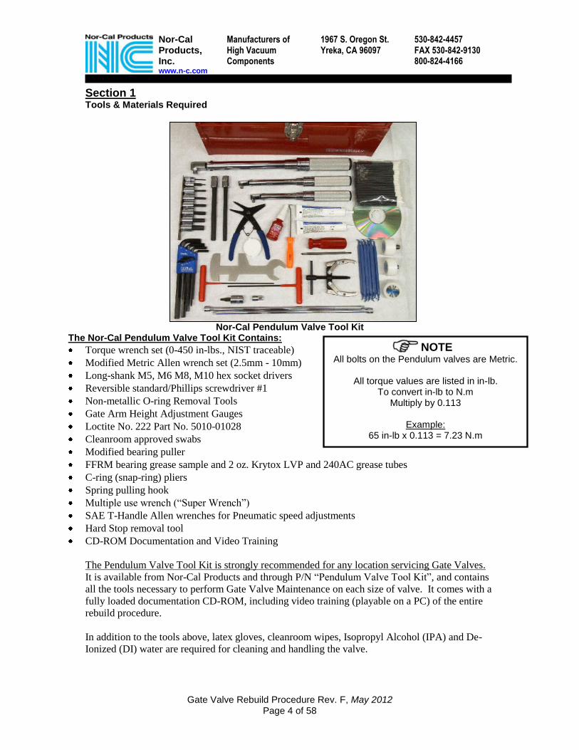
Nor-Cal Pendulum Valve Tool Kit The Nor-Cal Pendulum Valve Tool Kit Contains:
Torque wrench set (0-450 in-lbs., NIST traceable)
Modified Metric Allen wrench set (2.5mm - 10mm)
Long-shank M5, M6 M8, M10 hex socket drivers
Reversible standard/Phillips screwdriver #1
Non-metallic O-ring Removal Tools
Gate Arm Height Adjustment Gauges
Loctite No. 222 Part No. 5010-01028
Cleanroom approved swabs
Modified bearing puller
FFRM bearing grease sample and 2 oz. Krytox LVP and 240AC grease tubes
C-ring (snap-ring) pliers
Spring pulling hook
Multiple use wrench (“Super Wrench”)
SAE T-Handle Allen wrenches for Pneumatic speed adjustments
Hard Stop removal tool
CD-ROM Documentation and Video Training
The Pendulum Valve Tool Kit is strongly recommended for any location servicing Gate Valves.
It is available from Nor-Cal Products and through P/N “Pendulum Valve Tool Kit”, and contains
all the tools necessary to perform Gate Valve Maintenance on each size of valve. It comes with a
fully loaded documentation CD-ROM, including video training (playable on a PC) of the entire
rebuild procedure.
In addition to the tools above, latex gloves, cleanroom wipes, Isopropyl Alcohol (IPA) and De-
Ionized (DI) water are required for cleaning and handling the valve.
NOTE All bolts on the Pendulum valves are Metric.
All torque values are listed in in-lb.
To convert in-lb to N.m Multiply by 0.113
Example:
65 in-lb x 0.113 = 7.23 N.m

Nor-Cal Products, Inc. www.n-c.com
Manufacturers of High Vacuum Components
1967 S. Oregon St. Yreka, CA 96097
530-842-4457 FAX 530-842-9130 800-824-4166
Gate Valve Rebuild Procedure Rev. F, May 2012 Page 5 of 58
Section 2 Spare Parts Available [Please refer to Appendix A for a complete list of spare parts]
[Figure 2-A, Spare Part Kits Photos]
220000mmmm HHaarrdd SSttoopp
Photos of Spares & Kits NOTE: Spares Kit photos are examples only.
Kits for specific valve configurations may vary accordingly

Nor-Cal Products, Inc. www.n-c.com
Manufacturers of High Vacuum Components
1967 S. Oregon St. Yreka, CA 96097
530-842-4457 FAX 530-842-9130 800-824-4166
Gate Valve Rebuild Procedure Rev. F, May 2012 Page 6 of 58
Section 3 Grease and Torque Standards
This section covers the requirements for the amount of grease to be applied when reassembling
the gate valve. Since there is a possibility for additional particles generated with excessive grease
application, it is important to follow the guidelines listed below. Additionally, this section
includes the torque standards for installing hardware.
3.1 The assembly section will refer to the standard for grease application as "one bead."
3.2 One bead of Krytox LVP or 240-AC should be a sphere, approximately 3mm in
diameter, applied from a tube (Figure 3-A)
3.3 DI water should be used as a lubricant for bolts. Never use grease on bolts.
Shaft Seals Krytox LVP
Shaft Bearings Lubriplate
Crank Arm, Knuckle, Case Lubriplate
Gate Assembly Driving Rollers Krytox 240AC
Hard Stop O-ring No Grease – IPA + DI Wipe Only
Gate Seal O-Ring No Grease – IPA + DI Wipe Only
Bonnet Seal O-Ring No Grease – IPA + DI Wipe Only
[Figure 3-A, Standard Grease Amount] [Table T-1, Grease Types and Locations]
Table T-2, Torque Table
350mm 250mm 200mm
Fastener Description Torque (in.-lbs.) Torque (in.-lbs.) Torque (in.-lbs.)
Crank Arm Hex Socket Head Bolt 130 130 130 (65 for Flag-
Pole)
Crank Arm Hex Socket Head Set Screws 100 100 100
Actuator (Case fixing) Hex Socket Head Bolts 160 130 130
Bearing Flange / Shaft Guide Housing Hex Socket Head Bolts 65 35 35
Plate Spring Hex Socket Head Bolts 20 15 15
Holder Hex Socket Head Bolts 70 50 30
Touch Plate Flat Hex Socket Head Screws 30 30 30
Gate Arm Hex Socket Head Bolt 210 130 65
Hard Stop Hex Head Bolts * * 30
Power Bolt (Hex Socket Head) 450 350 150
Spring Cover Plate Captive Hex Socket Head Bolts 25 25 25
Bonnet Captive Hex Socket Head Bolts 100 100 100
Connecting Bar Hex Socket Head Bolts 70 50 30
Gate Stopper Hex Socket Head Bolts 50 25 15
Gate Supporter Hex Socket Head Bolt 70 n/a n/a
* Torque Values for Hard Stop Hex Head Bolts
Hard Stop Material 350mm Gate Valve 250mm Gate Valve
Vespel 30 in-lb 30 in-lb
1 Bead
Nor-Cal Products, Inc. www.n-c.com
Manufacturers of High Vacuum Components
1967 S. Oregon St. Yreka, CA 96097
530-842-4457 FAX 530-842-9130 800-824-4166
Gate Valve Rebuild Procedure Rev. F, May 2012 Page 7 of 58
Section 4 Gate Assembly Removal
4.1 Open the Gate Valve
4.2 Follow the prescribed venting procedure to vent the process chamber. Before continuing,
check the turbo controller to confirm the turbo is spun down (0 rpm or wait at least 30
minutes for Shimadzu turbo pumps.)
4.3 Vent the turbo pump by removing the VCR cap on the turbo isolation valve. Reinstall the
VCR cap with a new VCR gasket once atmospheric pressure in the turbo pump is
reached.
CAUTION There may be a pressure difference between the turbo pump and the chamber. Maximum differential pressure across the 350 gate during actuation is 29 Torr. Maximum differential pressure across the 250 gate during actuation is 24 Torr. Maximum differential pressure across the 200 gate during actuation is 20 Torr. I.E., the ΔP between the turbo and the chamber is not to exceed these values
when actuating the gate valve. Actuating the gate valve at pressures in excess of this maximum will cause permanent damage and invalidate the warranty.
4.4 Return the Gate Valve to the closed position, and remove the Bonnet by loosening the
captive bonnet bolts.
For Pneumatically actuated Isolation Valves, Skip to section 4.6, “Retracting the Gate on a Pneumatically Actuated Valve”
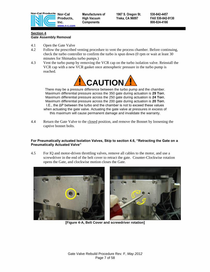
4.5 For IQ and motor-driven throttling valves, remove all cables to the motor, and use a
screwdriver in the end of the belt cover to retract the gate. Counter-Clockwise rotation
opens the Gate, and clockwise motion closes the Gate.
[Figure 4-A, Belt Cover and screwdriver rotation]

Nor-Cal Products, Inc. www.n-c.com
Manufacturers of High Vacuum Components
1967 S. Oregon St. Yreka, CA 96097
530-842-4457 FAX 530-842-9130 800-824-4166
Gate Valve Rebuild Procedure Rev. F, May 2012 Page 8 of 58
CAUTION The Actuator and motor linkage are subject to permanent damage if
handled improperly. Never use the motor or actuator as a handle to lift the valve. Serious damage may result.
Never rest the valve on the motor or actuator when unpacking, moving or servicing the valve, and avoid hitting the motor against heavy objects.
Under normal service and preventive maintenance conditions, the motor linkage and
actuator assembly will not have to be disassembled or removed from the valve.
However under certain conditions, the motor and belt pulley may need to be removed for service.
Please refer this type of service to a trained and qualified technician.
Intellisys
WARNING NO ANGULAR MOTION
WHEN REMOVING MOTOR BLOCK!

Nor-Cal Products, Inc. www.n-c.com
Manufacturers of High Vacuum Components
1967 S. Oregon St. Yreka, CA 96097
530-842-4457 FAX 530-842-9130 800-824-4166
Gate Valve Rebuild Procedure Rev. F, May 2012 Page 9 of 58
Retracting the Gate on a Pneumatically Actuated Valve
4.6 Open the gate valve manually by pressing and holding the orange button on the Air
Control Assembly, mounted next to the piston cylinder case housing. Use an o-ring pick
or small Allen wrench to operate the button.
DANGER With the bonnet removed, the gate assembly will protrude out of the opening of the gate valve body in the open position. Keep personnel clear of the bonnet opening when manually opening the gate valve.
[Figure 4-B, Gate Valve Pneumatics]
4.7 Remove the main air supply line and pinch it off as soon as the gate valve is open.
[Figure 4-C, Remove the main air supply line]

Nor-Cal Products, Inc. www.n-c.com
Manufacturers of High Vacuum Components
1967 S. Oregon St. Yreka, CA 96097
530-842-4457 FAX 530-842-9130 800-824-4166
Gate Valve Rebuild Procedure Rev. F, May 2012 Page 10 of 58
4.8 With the main air line removed, vent the cylinder by pressing and holding the red button
on the air control bracket for ~20 seconds. Then remove the open and close air lines
from the Air Control Assembly. This will allow the actuator to move freely.
[Figure 4-D, Vent the Cylinder and remove the air lines]
Removing the Gate Assembly from the valve
4.9 Loosen the two captive bolts from the spring cover on bottom of gate assembly [A] and
remove spring using the spring hook removal tool, or a plastic zip-tie [B]. To prevent
scratching the gate, never use a metal screwdriver or other unapproved tool.
[Figure 4-E, Gate Valve Spring Assembly]
AA BB

Nor-Cal Products, Inc. www.n-c.com
Manufacturers of High Vacuum Components
1967 S. Oregon St. Yreka, CA 96097
530-842-4457 FAX 530-842-9130 800-824-4166
Gate Valve Rebuild Procedure Rev. F, May 2012 Page 11 of 58
4.10 Using the appropriate long shank, hex socket driver, remove Power Bolt and Power Bolt
Washer from the bottom center of the Gate assembly.
[Figure 4-F, Removing the Power Bolt]
CAUTION If the Power Bolt does not come out easily, do not force it out. Use DI
water as a lubricant, by squirting it into the threads. Ease-out the Power Bolt by using a back & forth motion and large amounts of DI to slowly
work it out. Inspect the Power Bolt and Gate Arm as in step 4.12
4.11 Do not remove the touch plate at this time. Remove the Gate from the Gate Arm by
lifting the Gate off the arm and sliding it out, being careful not to scratch the Gate in the
process.
[Figure 4-G, Lift-up and slide-out the Gate Assembly]

Nor-Cal Products, Inc. www.n-c.com
Manufacturers of High Vacuum Components
1967 S. Oregon St. Yreka, CA 96097
530-842-4457 FAX 530-842-9130 800-824-4166
Gate Valve Rebuild Procedure Rev. F, May 2012 Page 12 of 58
4.12 Inspect Power Bolt threads and note their integrity. Inspect Gate Arm threads and note
the presence of any particles. Thoroughly clean any particles from Power Bolt threads
and Gate Arm threads with IPA or DI, and cleanroom wipes, until no trace of particles is
left in either.
[Figure 4-H, Check the Power Bolt threads for debris]
4.13 Inspect the Gate arm and Power Bolt for past over torque damage. Look for damaged
threads on the Power Bolt and for a “mushroomed” shoulder where the unthreaded
portion has expanded. In the Gate Arm, look for a small recess where the Power Bolt has
dug-in to the Arm (Fig 4-I below.) If either of these conditions is present, the Gate Plate
may not rotate properly. See Section 12.4 for information on proper Gate rotation.
[Figure 4-I, Inspect the Gate Arm and Power Bolt for over torque damage.]
4.14 Test the condition of the Power Bolt by threading the entire length into and out of the
Gate Arm thread by hand. If the Power Bolt does not move freely throughout the travel,
there may be debris in the threads. In this case, loosen Power Bolt, clean all threads and
re-try. If this does not solve the problem, try a new Power Bolt. If still, this does not
solve the problem, the Gate Arm threads are damaged. Replace both the Gate Arm and
Power Bolt.
No debris here

Nor-Cal Products, Inc. www.n-c.com
Manufacturers of High Vacuum Components
1967 S. Oregon St. Yreka, CA 96097
530-842-4457 FAX 530-842-9130 800-824-4166
Gate Valve Rebuild Procedure Rev. F, May 2012 Page 13 of 58
Section 5 Disassembly and Cleaning of the Gate Assembly
[Figure 5-A, Gate Assembly Exploded View]
[Table T2, Gate Assembly Exploded View Legend]
Item Description Item Description A Power Bolt K Driving Pieces (350 Only) B Polyimide Power Bolt Washer L Gate Support (Driving Bar in 350) C Polyimide Rotary Pad M Holders (4) D Rollers (4) N Connecting Bars (2) E Protect Pipes (4) 350 Only O Counter Plates (2) F Gate Stopper P Gate Plate G Polyimide Slide pads (8) Q Gate Stopper Bolts (2) H Flat Head Touch Plate Screws (4) R Coil Spring Cover I Plate Spring Screws (16) S Coil Spring J Plate Springs (4)
BB
AA
CC
DD
EE
FF
GG
JJ
II
HH
JJ JJ
JJ
KK
LL
MM
NN
KK
MM MM
MM
NN
OO
OO
PP
RR
SS

Nor-Cal Products, Inc. www.n-c.com
Manufacturers of High Vacuum Components
1967 S. Oregon St. Yreka, CA 96097
530-842-4457 FAX 530-842-9130 800-824-4166
Gate Valve Rebuild Procedure Rev. F, May 2012 Page 14 of 58
Recommended Cleaning and Rebuilding (Preventive Maintenance) Kit (Recommended at each PM interval) Crash Kit
N-C 200mm Crash Kit 72-00033
N-C 250mm Crash Kit 72-00003
N-C 350mm Crash Kit 72-00054
Recommended Gate Assembly refurbishing and parts replacement kits (Replace on failure, or as needed per inspection to prevent failure) Drive Kit
N-C 200mm Drive Kit (STD) 72-00020
N-C 200mm Drive Kit (SYM) 72-00068
N-C 250mm Drive Kit 72-00007
N-C 350mm Drive Kit IPV-00998-950
Spring Kit
N-C 200mm Spring Kit 72-00064
N-C 250mm Spring Kit 72-00009
N-C 350mm Spring Kit 72-00023
Poly Pad Kit
N-C 200mm Poly Pad Kit 72-00066
N-C 250mm Poly Pad Kit 72-00002
N-C 350mm Poly Pad Kit IPV-350-40
Power Bolt
N-C 200mm Power Bolt 56-02055
N-C 250mm Power Bolt 72-00012
N-C 350mm Power Bolt 56-05058

Nor-Cal Products, Inc. www.n-c.com
Manufacturers of High Vacuum Components
1967 S. Oregon St. Yreka, CA 96097
530-842-4457 FAX 530-842-9130 800-824-4166
Gate Valve Rebuild Procedure Rev. F, May 2012 Page 15 of 58
5.1 Place the Gate Assembly with the o-ring side down on a clean wipe and remove the 4
flat-head Touch Plate screws and the Touch Plate. Inspect the Touch Plate for damage
such as scratches or bending, as shown in Fig 5-B.
[Figure 5-B, Removing and inspecting the Touch Plate]
5.2 Completely remove all 4 Plate Springs from the Counter Plates and Holders.
[Figure 5C, Removing the Touch Plate Screws]
5.3 Remove four bolts holding the Counter Plates together with the Connecting Bars (square
cross pieces).
[Figure 5-D, Removing Connecting Bar bolts]

Nor-Cal Products, Inc. www.n-c.com
Manufacturers of High Vacuum Components
1967 S. Oregon St. Yreka, CA 96097
530-842-4457 FAX 530-842-9130 800-824-4166
Gate Valve Rebuild Procedure Rev. F, May 2012 Page 16 of 58
5.4 Remove the Counter Plates by pulling on both ends equally and removing them straight.
The Counter Plates should come off easily. Avoid rocking the Counter Plates back &
forth to remove them. Never use a hammer or pry-bar to remove the Counter Plates.
[Figure 5-E, Remove Counter plates straight]
5.5 Remove the eight Holder bolts fastening the four Holders. Lift up on the Gate Support
and remove the Holders. Never write on the holders – they will stain.
[Figure 5-F, Removing the Holders]
5.6 Remove the four Rollers and the Protect Pipes (350 only.) Finally, lift the Gate
Supporter clear of the Gate Plate.

Nor-Cal Products, Inc. www.n-c.com
Manufacturers of High Vacuum Components
1967 S. Oregon St. Yreka, CA 96097
530-842-4457 FAX 530-842-9130 800-824-4166
Gate Valve Rebuild Procedure Rev. F, May 2012 Page 17 of 58
5.7 Inspect the Gate Stopper assembly for damage (refer to damaged Gate Stopper in Figure
5-G). Look for a crushed or bent pipe on the end, and any bending of the flat arm that
attaches to the Gate. If there is significant damage, replace the Gate Stopper assembly
[Figure 5-G, Check for Gate Stopper Damage]

Nor-Cal Products, Inc. www.n-c.com
Manufacturers of High Vacuum Components
1967 S. Oregon St. Yreka, CA 96097
530-842-4457 FAX 530-842-9130 800-824-4166
Gate Valve Rebuild Procedure Rev. F, May 2012 Page 18 of 58
5.8 Remove all Polyimide Slide Pads including the large Rotary Pad underneath the gate
Support, using cleanroom tape. Avoid using a metal tool to remove the pads, as it can
scratch the Aluminum or destroy the pad. Clean off any grease. When re-installing Pads,
do not use grease. Slide Pads should be replaced if they are worn flush with the metal
surface, or the rounded edge is worn flat
[Figure 5-H, Slide Pad Removal]
5.9 Thoroughly clean all parts using 100% IPA, cleanroom swabs and cleanroom wipes.
Parts may be very dirty. See Figure 5-I for examples. A DI rinse and wipe is
recommended to remove the IPA residue. Use clean dry disposable cleanroom wipes to
remove excess DI water.
[Figure 5-I, Examples of high-cycle Holder and Roller wear]

Nor-Cal Products, Inc. www.n-c.com
Manufacturers of High Vacuum Components
1967 S. Oregon St. Yreka, CA 96097
530-842-4457 FAX 530-842-9130 800-824-4166
Gate Valve Rebuild Procedure Rev. F, May 2012 Page 19 of 58
Section 6 Re-assembling the Gate Assembly
NOTE Each bolt in the Gate Assembly has a specific torque value.
Refer to the small torque table at each location for the specific torque on each bolt.
6.1 Align the Gate Stopper in the center of its recess on the Gate plate, and pushed all the
way in towards the center of the Gate, and torque the Gate Stopper assembly bolts.
[Figure 6-A, Align and install the Gate Stopper]
6.2 Apply one bead of Krytox® 240AC to the inside of each Counter Plate Roller slot,
Holder Roller slot, and Gate Supporter Roller slot. Spread evenly inside the Roller slots
with a cleanroom swab. Use a clean swab or wipe to remove any excess grease that
migrates out of the Roller slots.
[Figure 6-B, Apply 1 bead of Krytox 240AC to each track]
350 Valve 250 Valve 200 Valve
50 in-lb. 25 in-lb. 15 in-lb.
00..00

Nor-Cal Products, Inc. www.n-c.com
Manufacturers of High Vacuum Components
1967 S. Oregon St. Yreka, CA 96097
530-842-4457 FAX 530-842-9130 800-824-4166
Gate Valve Rebuild Procedure Rev. F, May 2012 Page 20 of 58
[Figure 6-C, Inspecting Grease Application]
6.3 Change Gloves. Clean off the Gate Plate with cleanroom wipes and swabs, using DI or
IPA to remove all fingerprints and residue from the recesses of the plate.
6.4 Inspect each holder recess (boss) for damage. Look for damage on the edges of the boss
from improper handling or metal tools. Replace the Gate Plate if damage is found.
[Figure 6-D, Inspecting the Holder recesses]

Nor-Cal Products, Inc. www.n-c.com
Manufacturers of High Vacuum Components
1967 S. Oregon St. Yreka, CA 96097
530-842-4457 FAX 530-842-9130 800-824-4166
Gate Valve Rebuild Procedure Rev. F, May 2012 Page 21 of 58
6.5 Gently place the Gate Support on the Gate plate, taking note of the recessed holes for the
gate Stopper Bolts.
[Figure 6-E, Gate Support Recesses]
6.3 Apply 1 bead of Krytox® 240AC to each of the Rollers. With a gloved hand, spread the
grease evenly over the entire shaft and the tips of the Rollers. The coating should be a
uniform, nearly invisible sheen, rather than a “coat” of grease. Refer to Figure 6-C for the
proper grease amount.
[Figure 6-F, Add 1 bead of grease to each Holder and spread evenly]
6.4 Slide the greased Rollers through the bottom holes of the Gate Supporter, through the
protect pipes, and all the way in to the Holders. Do not force the Rollers in. They should
slide easily. If there is resistance, inspect tracks and rollers for damage. Replace as
needed. Never use sandpaper or abrasives to clean or smooth rollers.
[Figure 6-G, Rollers slide in easily. Never use tools to force rollers in]
RRoottaarryy
PPaadd

Nor-Cal Products, Inc. www.n-c.com
Manufacturers of High Vacuum Components
1967 S. Oregon St. Yreka, CA 96097
530-842-4457 FAX 530-842-9130 800-824-4166
Gate Valve Rebuild Procedure Rev. F, May 2012 Page 22 of 58
6.5 With a swab, remove any grease that scrapes off the Rollers onto the outer edges of the
Roller slots or Protect Pipes.
[Figure 6-H, Clean off any excess grease with a swab]
6.6 Add a drop of DI water to each Slide Pad recess, and install the slide pads in the Holders.
Wipe off any excess DI Water.
[Figure 6-I, Add a drop of DI water and install the Slide Pads]
NOTE
On valves manufactured in 2006 and later the Slide Pads are rounded on both sides, eliminating the flat side.
6.7 Re-install the Holders in their recessed spaces. Each Holder works in only one location.
The kidney bean-shaped tracks in the Holders slope UP towards the Gate Stopper (see
Figure 6-J).
[Figure 6-J, All Holder tracks slope UP towards Gate Stopper]

Nor-Cal Products, Inc. www.n-c.com
Manufacturers of High Vacuum Components
1967 S. Oregon St. Yreka, CA 96097
530-842-4457 FAX 530-842-9130 800-824-4166
Gate Valve Rebuild Procedure Rev. F, May 2012 Page 23 of 58
CAUTION Alignment of the Holders is the most important step in the
rebuild procedure. If the Holders are not aligned correctly, the Gate Assembly can jam, causing major problems. If there is
binding in step 6.10, re-align the Holders. If binding cannot be removed, replace ALL of the holders and rollers.
6.8 Align the Holders: Squeeze the two Holders closest to the Gate Supporter towards each
other, and at the same time towards the center of the gate. Hold, and tighten the Holder
bolts. It may help to have one person to tighten, while one keeps the Holders in place.
[Figure 6-K. Alignment of Holders]
6.9 Do the same for the other two Holders. Push together and towards the center of the plate,
holding them in place while they are tightened to the specification above. It may help to
have one person hold, while the other person tightens the bolts.
6.10 Check the Holders for correct alignment by pushing down on the Gate Supporter and
rocking the Gate Assembly Back & Forth, as in Fig 6-L. There should be no binding in its
movement. If there is binding in the movement, re-align the holders. If binding cannot be
removed, inspect the tracks and rollers and re-align or replace parts as necessary.
[Figure 6-L. Alignment of Holders]
350 Valve 250 Valve 200 Valve
70 in-lb. 50 in-lb. 30 in-lb.

Nor-Cal Products, Inc. www.n-c.com
Manufacturers of High Vacuum Components
1967 S. Oregon St. Yreka, CA 96097
530-842-4457 FAX 530-842-9130 800-824-4166
Gate Valve Rebuild Procedure Rev. F, May 2012 Page 24 of 58
6.11 Install the remaining 2 Rollers. Wipe off any excess grease near the roller slots and do
not force Rollers into Holders.
6.12 Add The Counter Plates. The Counter Plate tracks slope DOWN towards the Gate
Stopper. Ensure that they are installed parallel, not diagonal.
[Figure 6-M. Counter Plate Slope and Installation]
6.13 Install the Connecting Bars between the Counter Plates using the Connecting Bar bolts &
split washers, but do not tighten.
6.14 Align the Counter Plates by pushing the Counter Plates to one end of their track, while
lightly tightening Connecting Bar bolts. This ensures the counter plates are at the end of
their travel in the tracks, and that they are aligned together.
[Figure 6-N. Align the Counter Plates]
Nor-Cal Products, Inc. www.n-c.com
Manufacturers of High Vacuum Components
1967 S. Oregon St. Yreka, CA 96097
530-842-4457 FAX 530-842-9130 800-824-4166
Gate Valve Rebuild Procedure Rev. F, May 2012 Page 25 of 58
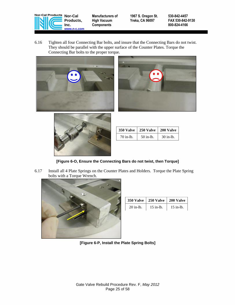
6.16 Tighten all four Connecting Bar bolts, and insure that the Connecting Bars do not twist.
They should be parallel with the upper surface of the Counter Plates. Torque the
Connecting Bar bolts to the proper torque.
[Figure 6-O, Ensure the Connecting Bars do not twist, then Torque]
6.17 Install all 4 Plate Springs on the Counter Plates and Holders. Torque the Plate Spring
bolts with a Torque Wrench.
[Figure 6-P, Install the Plate Spring Bolts]
350 Valve 250 Valve 200 Valve
70 in-lb. 50 in-lb. 30 in-lb.
350 Valve 250 Valve 200 Valve
20 in-lb. 15 in-lb. 15 in-lb.
Nor-Cal Products, Inc. www.n-c.com
Manufacturers of High Vacuum Components
1967 S. Oregon St. Yreka, CA 96097
530-842-4457 FAX 530-842-9130 800-824-4166
Gate Valve Rebuild Procedure Rev. F, May 2012 Page 26 of 58
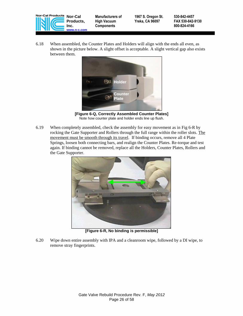
6.18 When assembled, the Counter Plates and Holders will align with the ends all even, as
shown in the picture below. A slight offset is acceptable. A slight vertical gap also exists
between them.
[Figure 6-Q, Correctly Assembled Counter Plates] Note how counter plate and holder ends line up flush.
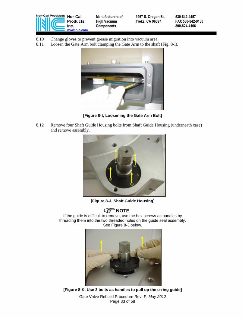
6.19 When completely assembled, check the assembly for easy movement as in Fig 6-R by
rocking the Gate Supporter and Rollers through the full range within the roller slots. The
movement must be smooth through its travel. If binding occurs, remove all 4 Plate
Springs, loosen both connecting bars, and realign the Counter Plates. Re-torque and test
again. If binding cannot be removed, replace all the Holders, Counter Plates, Rollers and
the Gate Supporter.
[Figure 6-R, No binding is permissible]
6.20 Wipe down entire assembly with IPA and a cleanroom wipe, followed by a DI wipe, to
remove stray fingerprints.
HHoollddeerr
CCoouunntteerr
PPllaattee

Nor-Cal Products, Inc. www.n-c.com
Manufacturers of High Vacuum Components
1967 S. Oregon St. Yreka, CA 96097
530-842-4457 FAX 530-842-9130 800-824-4166
Gate Valve Rebuild Procedure Rev. F, May 2012 Page 27 of 58
6.21 Install the Touch Plate and torque the Touch Plate flat head screws. The hole in the center
of the Touch Plate lines up over the hole in the Gate Supporter. It will only work one
way. Inspect the Touch Plate for scratches or bending
[Figure 6-S, Correct Touch Plate installation]
6.22 Check for warping of the Touch Plate after install. It should lie flat on the Counter Plates.
(See Figure 6-T) If there is warping, try loosening the Touch Plate flat-head screws, and
re-torquing them evenly in a quad-pattern, each a little at a time until they all reach 30 in-
lb. If the Touch Plate will not lie flat, replace it with a new Touch Plate.
[Figure 6-T, Touch Plate lies flat on counter plates]
350 Valve 250 Valve 200 Valve
30 in-lb. 30 in-lb. 30 in-lb.
IInnccoorrrreecctt CCoorrrreecctt

Nor-Cal Products, Inc. www.n-c.com
Manufacturers of High Vacuum Components
1967 S. Oregon St. Yreka, CA 96097
530-842-4457 FAX 530-842-9130 800-824-4166
Gate Valve Rebuild Procedure Rev. F, May 2012 Page 28 of 58
Section 7 O-ring Removal and Installation
The Pendulum Gate Valve line has many different o-ring sizes, compounds and cross-sections.
The correct o-ring must be installed properly, or else it will leak.
NOTE
NO Grease should be applied for o-ring installation.
7.1 Remove the old o-ring with an o-ring pick. Never use a metallic tool or screwdriver.
Use DI water as a lubricant if necessary. Thoroughly clean the groove with IPA and a
wipe.
[Figure 7-A Removing the O-ring, and cleaning the groove]
For D-shaped, or “teardrop” cross-section o-rings, skip to Step 7.4
Round O-rings
7.2 Using DI water as a lubricant, partially fill the groove with DI, place the new o-ring on
the groove, and press it down in the groove with your thumbs at the 4 vent holes.
7.3 Once the first 4 points are seated, press the o-ring into the groove at points 180 apart,
going around the rest of the o-ring, seating it. Use as much DI as needed to facilitate
installation.
D-Seal or “teardrop” shaped o-rings
7.4 For the teardrop cross-section o-ring, a different method works best. Note that the point
of the o-ring goes towards the center of the Gate, and the flat side goes down in the
groove. Review the training video for a detailed demonstration.
7.5 Using DI water as a lubricant, partially fill the groove with DI, place the new o-ring on
the groove, and press it down in the groove with your thumb at one of the vent holes.
7.6 Next, stretch the O-ring to reduce its cross-section, and roll it into the groove.
7.7 Push-back the O-ring to relieve the stretch, then press, stretch and roll again continuing
around the gate.
7.8 Continue to push back the O-ring, so that the last section needs to be stretched to get in
the groove. The D-Seal will feel slightly loose in its groove.
7.9 Ensure that there are no twists or bumps in the o-ring after the o-ring is seated. Unlike a
round o-ring, a D-shaped o-ring will feel loose in the groove when completely installed.
7.10 Blow out the leftover DI by forcing CDA or Nitrogen into the 4 vent holes. Make sure
you’re wearing goggles, as DI will spray out from the other vent holes. Repeat on all 4
vent holes until no DI comes out.
7.11 Move the completed Gate Assembly to a safe area while servicing the rest of the valve.
.

Nor-Cal Products, Inc. www.n-c.com
Manufacturers of High Vacuum Components
1967 S. Oregon St. Yreka, CA 96097
530-842-4457 FAX 530-842-9130 800-824-4166
Gate Valve Rebuild Procedure Rev. F, May 2012 Page 29 of 58
Section 8 Actuator and Gate Arm Shaft Removal Required Shaft cleaning and rebuilding (Preventive Maintenance) Kit (Required at each Shaft PM interval) Seal Kit
N-C 200mm Seal Kit 72-00063
N-C 250mm Seal Kit 72-00004
N-C 350mm Seal Kit 72-00055
Recommended Shaft refurbishing and parts replacement kits (Replace on failure, or as needed per inspection to prevent failure) Case Kit
N-C 200mm Case Kit 72-00067
N-C 250mm Case Kit 72-00001
N-C 350mm Case Kit 070226-2
Air Solenoid Kit
N-C 250mm Air Solenoid Kit 72-00045
N-C 350mm Air Solenoid Kit 56-05084
Open Close Sensors
N-C 250mm IPV Open/Close Sensors 72-00062
N-C 350mm IPV Open/Close Sensors 72-00059
N-C 200mm TPV Closed Sensor 56-00023
N-C 250mm TPV Closed Sensor 56-00023

Nor-Cal Products, Inc. www.n-c.com
Manufacturers of High Vacuum Components
1967 S. Oregon St. Yreka, CA 96097
530-842-4457 FAX 530-842-9130 800-824-4166
Gate Valve Rebuild Procedure Rev. F, May 2012 Page 30 of 58
For Pneumatic Isolation Valves, skip to section 8.5
DANGER Remove all power to the valve motor and controller before opening the case cover.
Removing a rotary flag sensor (for a linear sensor, skip to Step 8.4)
8.1 Remove the five Phillips screws from Actuator cover to access pivot shaft (Fig. 8-A)
[Figure 8-A, Throttling Gate Valve Actuator and cover screws]
8.2 Carefully rotate the case cover to remove the sensor assembly from the path of the flags,
and slowly lift off case cover. Do not force it off – you could break the plastic flags.
[Figure 8-B, Carefully twist and remove the cover]
8.3 Remove the “Flag Pole” by unscrewing it with the Nor-Cal “Super Wrench”
[Figure 8-C, Unscrew the “Flag Pole” with the Nor-Cal “Super Wrench”]

Nor-Cal Products, Inc. www.n-c.com
Manufacturers of High Vacuum Components
1967 S. Oregon St. Yreka, CA 96097
530-842-4457 FAX 530-842-9130 800-824-4166
Gate Valve Rebuild Procedure Rev. F, May 2012 Page 31 of 58
8.4 Removing a Linear Sensor: For a linear sensor, remove the 4 bolts holding the linear
sensor to the Case cover (1), then remove the 5 Phillips screws holding the Case cover (2).
[Figure 8-D, Remove the Linear Sensor]
8.5 Removing the Case on a Pneumatic Isolation valve requires removing the air lines and
Air Control Bracket, then removing the five Phillips screws in the Case cover.
[Figure 8-E, Remove the air lines]
NOTE During handling of the Actuator, it is highly recommended to wear double set of gloves, as the lubrication grease tends to
spread easily.
NOTE To prevent cross-contamination of Lubriplate grease with
vacuum grease, do not use the same set of tools to remove the actuator assembly and gate arm shaft as was used to remove
and disassemble the gate, or clean them thoroughly before use.
NOTE Be sure to keep hardened Loctite particles from getting onto the grease in the case. Promptly remove any particles that may fall
onto grease.
1
2

Nor-Cal Products, Inc. www.n-c.com
Manufacturers of High Vacuum Components
1967 S. Oregon St. Yreka, CA 96097
530-842-4457 FAX 530-842-9130 800-824-4166
Gate Valve Rebuild Procedure Rev. F, May 2012 Page 32 of 58
8.6 Loosen the two Crank Arm set screws holding the Crank Arm to the shaft, using the
access hole on the side of the case.
[Figure 8-F, Crank Arm Hex Bolt, Set Screws and Case Fixing Bolts]
8.7 Remove the three Actuator (Case fixing) bolts holding Actuator to the Gate Valve body
(Figure 8-F)
CAUTION Step 8.8 may require 2 individuals. Support actuator when removing
the hex bolts. The actuator will tend to drop due to its weight. Remove the guide pin in the body, and be careful not to lose it.
[Figure 8-G, Actuator Removal]
8.8 Remove the Case by pulling on both the Crank Arm and case at the same rate, keeping
them parallel. The Nor-Cal crank arm puller helps to remove the Crank Arm from the
shaft. I.E. turn the puller a little [1], then lift the case off a little [2], and repeat until
removed. Be careful not to spread the grease around.
8.9 Remove exposed bearing from shaft and place on a wipe.
NOTE If the bearing is not on the shaft, it is most likely still
encased inside the housing. The bearing must come off the shaft straight or it can jam on the shaft. Never use a
hammer to remove the bearing.
SSeett SSccrreewwss
CCaassee FFiixxiinngg BBoollttss
SSeett SSccrreeww
AAcccceessss HHoollee
SSeennssoorr FFllaagg PPoollee
11
22 22
½”
[Figure 8-H, Bearing Removal]
Nor-Cal Products, Inc. www.n-c.com
Manufacturers of High Vacuum Components
1967 S. Oregon St. Yreka, CA 96097
530-842-4457 FAX 530-842-9130 800-824-4166
Gate Valve Rebuild Procedure Rev. F, May 2012 Page 33 of 58
8.10 Change gloves to prevent grease migration into vacuum area.
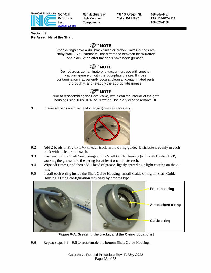
8.11 Loosen the Gate Arm bolt clamping the Gate Arm to the shaft (Fig. 8-I).
[Figure 8-I, Loosening the Gate Arm Bolt]
8.12 Remove four Shaft Guide Housing bolts from Shaft Guide Housing (underneath case)
and remove assembly.
[Figure 8-J, Shaft Guide Housing]
NOTE If the guide is difficult to remove, use the hex screws as handles by
threading them into the two threaded holes on the guide seal assembly. See Figure 8-J below.
[Figure 8-K, Use 2 bolts as handles to pull up the o-ring guide]

Nor-Cal Products, Inc. www.n-c.com
Manufacturers of High Vacuum Components
1967 S. Oregon St. Yreka, CA 96097
530-842-4457 FAX 530-842-9130 800-824-4166
Gate Valve Rebuild Procedure Rev. F, May 2012 Page 34 of 58
8.13 Pull out the shaft and place it on a wipe. In 350 valves you may need to use a screwdriver
as a lever to open up the gate arm clamp. (See Figure 8-L)
[Figure 8-L, Use a screwdriver as a lever to help open the 350 gate arm clamp]
NOTE The Shaft key may come loose from shaft, DO NOT lose the key!
8.14 From the other side of the valve, remove the four Bearing Flange bolts from the Bearing
Flange and remove assembly including bearing, wavy washer and Shaft Guide Housing
(top).
[Figure 8-M, Bearing Flange Stackup]
8.15 Remove three O-rings from each Shaft Guide Housing using a plastic o-ring pick.
8.16 Clean all parts thoroughly using 100% IPA and disposable cleanroom wipes. DO NOT
USE PRESATURATED WIPES.
8.17 Clean all grease from o-rings and Shaft Guide Housing using 100% IPA and disposable
cleanroom wipes. DO NOT USE PRESATURATED WIPES.
CAUTION Do not get Lubriplate grease inside the valve body or on the
gate assembly. It is not vacuum-safe grease.
(Not on 350)

Nor-Cal Products, Inc. www.n-c.com
Manufacturers of High Vacuum Components
1967 S. Oregon St. Yreka, CA 96097
530-842-4457 FAX 530-842-9130 800-824-4166
Gate Valve Rebuild Procedure Rev. F, May 2012 Page 35 of 58
8.18 NOTE: Perform this procedure for both sides of each bearing:
With a cleanroom wipe, wipe excess grease from both bearings removed earlier. Using
your finger, apply the Lubriplate grease to the bearing until the lubricant is worked in
between the bearings, leaving the race visible as shown.
[Figure 8-N, add grease to Bearings and wipe down]
Top Bearing Cover
Wavy Washer
Top Bearing
Top O-Ring Guide
Gate Arm
Key
Bottom O-Ring Guide
Bottom Bearing
Case NC
Actuator
Shaft Exploded View (Not to scale)
Add Grease to bearing Wipe off excess Correct Amount Too much grease!
Nor-Cal Products, Inc. www.n-c.com
Manufacturers of High Vacuum Components
1967 S. Oregon St. Yreka, CA 96097
530-842-4457 FAX 530-842-9130 800-824-4166
Gate Valve Rebuild Procedure Rev. F, May 2012 Page 36 of 58
Section 9 Re Assembly of the Shaft
NOTE Viton o-rings have a dull black finish or brown, Kalrez o-rings are shiny black. You cannot tell the difference between black Kalrez
and black Viton after the seals have been greased.
NOTE
Do not cross-contaminate one vacuum grease with another vacuum grease or with the Lubriplate grease. If cross
contamination inadvertently occurs, clean all contaminated parts thoroughly, and re-apply the appropriate grease.
NOTE Prior to reassembling the Gate Valve, wet-clean the interior of the gate
housing using 100% IPA, or DI water. Use a dry wipe to remove DI.
9.1 Ensure all parts are clean and change gloves as necessary.
9.2 Add 2 beads of Krytox LVP to each track in the o-ring guide. Distribute it evenly in each
track with a cleanroom swab.
9.3 Coat each of the Shaft Seal o-rings of the Shaft Guide Housing (top) with Krytox LVP,
working the grease into the o-ring for at least one minute each.
9.4 Wipe off excess, and then add 1 bead of grease, lightly spreading a light coating on the o-
ring.
9.5 Install each o-ring inside the Shaft Guide Housing. Install Guide o-ring on Shaft Guide
Housing. O-ring configuration may vary by process type.
[Figure 9-A, Greasing the tracks, and the O-ring Locations]
9.6 Repeat steps 9.1 – 9.5 to reassemble the bottom Shaft Guide Housing.
Process o-ring Atmosphere o-ring
Guide o-ring

Nor-Cal Products, Inc. www.n-c.com
Manufacturers of High Vacuum Components
1967 S. Oregon St. Yreka, CA 96097
530-842-4457 FAX 530-842-9130 800-824-4166
Gate Valve Rebuild Procedure Rev. F, May 2012 Page 37 of 58
9.7 Apply ¼ bead of Krytox LVP on the shaft, at the top & bottom lip. This helps the o-
rings slide over the shaft.
9.8 Install the top Shaft Guide Housing into the Gate Valve body. Align the 4 holes of the
Shaft Guide Housing with the threaded holes of the Gate Valve housing.
[Figure 9-B, install the o-ring guide]
9.9 Center the bearing, wavy washer and bearing flange over the top of the Shaft Guide.
Secure the Bearing Flange with the four long Bearing Flange bolts with split washers,
and torque down according to the chart below.
NOTE The 350 valve does not have a wavy washer.
9.10 Place gate arm in housing with clamping bolt facing out and insert shaft through housing
and gate arm. Align the key on the shaft with the notch in the gate arm. For the 350
valve you may need a screwdriver to help open the gate arm clamp.
[Figure 9-C, install the Gate Arm (bolt out) and the Shaft. Check for Grease]
9.11 Wipe off all excess grease on the shaft, even on the back side that can't be seen.
350 Valve 250 Valve 200 Valve
65 in-lb. 35 in-lb. 35 in-lb.
Top Guide Cover
Wavy Washer (Not on 350)
Bearing Top O-Ring Guide
Valve Body

Nor-Cal Products, Inc. www.n-c.com
Manufacturers of High Vacuum Components
1967 S. Oregon St. Yreka, CA 96097
530-842-4457 FAX 530-842-9130 800-824-4166
Gate Valve Rebuild Procedure Rev. F, May 2012 Page 38 of 58
9.12 Slide gate arm up and down on the shaft, until it rests approximately 1-2 mm above the
shoulder. Lightly tighten the Gate Arm clamping bolt at this time.
9.13 Install the bottom Shaft Guide (see Figure 9-D). You may need to push the shaft into the
body or support the Gate Arm to center the shaft in the o-ring Guide. Secure the
assembly using the four short Shaft Guide Housing bolts with split washers.
[Figure 9-D, Install the Bottom O-Ring Guide]
9.14 Install the bearing onto the Shaft. It must go on straight or it will jam. Never use a
hammer to install this bearing.
[Figure 9-E, Install the Bearing straight on the Shaft]
9.15 Place the Gate arm in the center of the bore of the valve, and mount the actuator assembly
back on Gate Valve housing. Align the square of the shaft with crank arm, and rotate the
Actuator until it aligns with the guide pin on the Gate Valve housing.
350 Valve 250 Valve 200 Valve
65 in-lb. 35 in-lb. 35 in-lb.

Nor-Cal Products, Inc. www.n-c.com
Manufacturers of High Vacuum Components
1967 S. Oregon St. Yreka, CA 96097
530-842-4457 FAX 530-842-9130 800-824-4166
Gate Valve Rebuild Procedure Rev. F, May 2012 Page 39 of 58
Make sure the case lies flat against the valve body. Install the Case fixing bolts and flat
washers, and Torque the Case Fixing Bolts according to the chart below
[Figure 9-F, Case Fixing Bolts]
9.16 Apply Loctite on the Crank Arm bolt (or “Flag Pole”) and install with the cover washer
on the end of the shaft over the Crank Arm. Torque a Stainless hex-head bolt to 75 in-lb.,
and use 65 for the sensor flag pole.
9.17 Unscrew, apply Loctite and re-tighten the two Crank Arm set screws on the crank arm to
the shaft. Rotate the Gate Arm back and forth to access backside set screw. Torque the
set screws to 100 in-lb (all sizes.)
9.18 Replace the Case Cover and clean all tools with IPA to prevent grease contamination.
NOTE During handling of the Actuator it is highly recommended to
change gloves often, as the crankcase lubrication grease tends to spread easily.
CAUTION Do not get Lubriplate grease inside the valve body or on the gate
assembly. It is not vacuum-safe grease.
NOTE Be sure to keep hardened Loctite particles from getting onto the grease
in the case. Promptly remove any particles that may fall onto grease.
350 Valve 250 Valve 200 Valve
160 in-lb. 130 in-lb. 130 in-lb.
Flag Pole
65 in-lb.
Hex Bolt
75 in-lb.
CCaassee FFiixxiinngg BBoollttss

Nor-Cal Products, Inc. www.n-c.com
Manufacturers of High Vacuum Components
1967 S. Oregon St. Yreka, CA 96097
530-842-4457 FAX 530-842-9130 800-824-4166
Gate Valve Rebuild Procedure Rev. F, May 2012 Page 40 of 58
Section 10
Gate Arm Height Adjustment 200mm Gate Arm Height Gauge 250mm Gate Arm Height Gauge 350mm Gate Arm Height Gauge
020929-1 020602-1 020602-2
All of the above gauges are included in the Nor-Cal Tool Kit
Align and tighten Gate Arm per the following procedure. This is the Best Known Method (BKM)
to correctly adjust the Gate Arm height. Do not use any other methods used in the past.
NOTE
It is important to understand that the Gate Arm Height Gauge is not a tool to set the height, but a Gauge to measure the height you set.
10.1 Raise/lower the Gate Arm until it is approximately 1mm above the lip on the shaft, then
lightly tighten the Gate Arm bolt. 1mm is a good starting point. (Figure 10-A)
10.2 Hand-tighten the correct Height Adjustment Gauge on to the Gate Arm (Figure 10-B)
10.3 Rotate the Gate Arm until the height adjustment tool is above the inner raised/machined
surface of the Gate Valve housing, and inspect the gap between the gauge and the lip.
[Figure 10-C, Inspect the gap between the Gauge and the inner flange]
[Figure 10-A, Initially adjust the Gate Arm
to 1mm above the lip on the Shaft]
[Figure 10-B, Install the Height Adjustment
Gauge on the Gate Arm]
Shaft
Arm
Lip ~1mm

Nor-Cal Products, Inc. www.n-c.com
Manufacturers of High Vacuum Components
1967 S. Oregon St. Yreka, CA 96097
530-842-4457 FAX 530-842-9130 800-824-4166
Gate Valve Rebuild Procedure Rev. F, May 2012 Page 41 of 58
10.4 If the Gate Arm Height Gauge touches the lip of the flange, then the Gate Arm Height
must be raised. If there is a gap between the gauge and the lip, slide 1 piece of cleanroom
paper between the Gauge and the lip, to check for clearance.
[Figure 10-D, To inspect the gap, slide 1 sheet of cleanroom paper between
the Gauge and the inner flange]
10.5 Determine the height of the Gate Arm:
10.5.1 If the cleanroom paper does not fit between the Gauge and the lip, the Gate Arm is
too low. Raise the gate arm slightly, and return to Step 10.3
10.5.2 If the cleanroom paper easily slides between the gauge and the lip with no resistance,
then the Gate Arm is too high. Lower the gate arm slightly, and return to Step 10.3
10.5.3 If the paper slides between the gauge and the lip with some resistance, the Gate Arm
Height is set correctly. Proceed to Step 10.6
10.6 When the height is set correctly, use a long-shank extension to torque the Gate Arm bolt.
It is a good idea to re-check the height after torquing the bolt.
[Figure 10-E, Torque the Gate Arm Height Bolt]
10.7 Remove the Gate Arm Height Adjustment Gauge from the Gate Arm.
350 Valve 250 Valve 200 Valve
210 in-lb. 130 in-lb. 65 in-lb.

Nor-Cal Products, Inc. www.n-c.com
Manufacturers of High Vacuum Components
1967 S. Oregon St. Yreka, CA 96097
530-842-4457 FAX 530-842-9130 800-824-4166
Gate Valve Rebuild Procedure Rev. F, May 2012 Page 42 of 58
Section 11 Replacing the Hard Stop Single Piece Hard Stops
Valve Size Nor-Cal
200mm 56-00022
250mm 72-00013
350mm 72-00035
Multiple-piece Hard Stops
Valve Size Nor-Cal 2-piece Hard Stop Nor-Cal 3-piece Hard Stop
250mm 72-00070 56-03097
350mm 72-00037 72-00038
NOTE There are many different types of hard stops for the Pendulum Valve
line. Please take note of which hard stop is used in your valve.
[Figure 11-A. Some different Hard Stop types]
NOTE To access the Hard Stop with the Gate Valve mounted on the tool, use the Hard Stop Removal tool provided in the Nor-Cal tool Kit.
For 200mm Pendulum Valves, please skip to step 11.7
11.1 For 250 and 350mm valves, remove the outer cap of the hard stop on the side of the
valve.
[Figure 11-B. Remove the Hard Stop Cap]

Nor-Cal Products, Inc. www.n-c.com
Manufacturers of High Vacuum Components
1967 S. Oregon St. Yreka, CA 96097
530-842-4457 FAX 530-842-9130 800-824-4166
Gate Valve Rebuild Procedure Rev. F, May 2012 Page 43 of 58
11.2 Use the Nor-Cal Hard Stop Removal Tool to push the hard stop through the body.
[Figure 11-C. Remove the Hard Stop Cap]
11.3 Remove the Hard Stop from the tool, and reverse the steps to reinstall the new hard stop
and o-ring.
[Figure 11-D, Installation of the hard stop]
11.4 Inspect 2-piece hard stops and Vespel Hard Stops for erosion from process chemicals.
On 2-piece hard stops, make sure there is no metal-to-metal contact from the Gate
Stopper hitting the metal plug of the 2-piece hard stop. If excessive wear or metal-to-
metal contact is observed, replace the hard stop.
1 2 3
4 5

Nor-Cal Products, Inc. www.n-c.com
Manufacturers of High Vacuum Components
1967 S. Oregon St. Yreka, CA 96097
530-842-4457 FAX 530-842-9130 800-824-4166
Gate Valve Rebuild Procedure Rev. F, May 2012 Page 44 of 58
11.5 When installing the Hard Stop, be sure the Hard Stop is square in the side of the body,
not diagonal (Figure 11-E). Look into the valve through the Bonnet, and inspect the
hard stop orientation with a flashlight before torquing the bolt.
[Figure 11-E, Incorrect (diagonal) installation of the hard stop]
11.6 Never apply Loctite to the hard stop bolt upon re-install
CAUTION Over torque will break the Vespel Hard Stop. Do not over torque the bolt.
11.7 For 200mm Hard Stops, use the Nor-Cal Hard Stop Extension and 3mm socket head to
remove the 2 flat-head bolts in the Hard Stop. There is no hole through the body.
11.8 Change the hard stop and replace the 2 flat-head bolts. Never apply Loctite to the Hard
Stop bolts.
11.9 When installed correctly, torque the Hard Stop bolts to 30 in-lb.
CAUTION The Hard Stop is a piston-seal type.
If there is a leak at the hard stop, increasing the torque WILL NOT stop the leak. Increasing the torque on the hard stop will break it! This can cause permanent damage to the Gate Valve and possibly other components of the system such as
the Turbo Pump. Make sure the hard stop is installed correctly. If you are unsure, ask a supervisor, or contact a local Nor-Cal Products representative.
NOTE A leak through the gate seal is an indicator that the hard stop is not installed correctly. If the Hard stop is installed incorrectly, the Gate will not fully close, and the o-ring may be visible (Fig 11-F)
[Figure 11-F, Gate does not close completely when hard stop is installed incorrectly.]
All Valves
30 in-lb.

Nor-Cal Products, Inc. www.n-c.com
Manufacturers of High Vacuum Components
1967 S. Oregon St. Yreka, CA 96097
530-842-4457 FAX 530-842-9130 800-824-4166
Gate Valve Rebuild Procedure Rev. F, May 2012 Page 45 of 58
Section 12 Installing the Gate Assembly
12.1 Spread ¼ bead of Krytox LVP bead on the non-threaded (shoulder) surface of the
Power Bolt.
[Figure 12-A, Spread ¼ bead on the Power Bolt shoulder]
12.2 Reinstall Gate Assembly back on to Gate Arm lifting it up and on, to avoid scratching the
underside of the Gate Assembly. Locate the threads in the gate arm with your little
finger, and center the Gate Assembly on the Gate Arm.
CAUTION DO NOT use Loctite when installing the Power Bolt.
12.3 Make sure the Power Bolt washer is oriented correctly, with the round side towards the
head of the bolt. This ensures the washer will lay flat on the Power Bolt without any gap.
[Figure 12-B, Install the Power Bolt Washer with the round side towards the head]

Nor-Cal Products, Inc. www.n-c.com
Manufacturers of High Vacuum Components
1967 S. Oregon St. Yreka, CA 96097
530-842-4457 FAX 530-842-9130 800-824-4166
Gate Valve Rebuild Procedure Rev. F, May 2012 Page 46 of 58
Use the long-shank socket extension to torque the Power Bolt.
[Figure 12-C, Torque the Power Bolt
12.4 After torquing the Power Bolt twist the Gate back and forth around the Power Bolt to
make sure the Gate assembly moves freely using only 2 fingers to hold it. (Figure 12-D.)
If there is binding, check the orientation of the Power Bolt washer in Step 12.3.
Switching to a slightly thinner Power Bolt washer may solve the binding problem.
[Figure 12-D, Check Gate for rotational binding and Gate wobble]
12.5 Check for Gate "wobble" by lifting up and down on both sides of the Gate. If there is
significant Gate wobble (more than 3mm of travel) the Power Bolt and/or Gate Arm
threads may be damaged. In this case, loosen Power Bolt, clean all threads, and re-try. If
this does not solve the wobble problem, replace the Power Bolt and the Gate Arm.
See Section 4.13 for more information on Power Bolt and Gate Arm damage.
NOTE No wobble and a loose, non-binding gate are ideal. However, it is
better to have a slight wobble than to have a tight gate that does not rotate. The Power Bolt Washer thickness and overtorque Damage
determines the amount of gate binding, and contributes to the degree of wobble. The Gate Arm and Power Bolt may need to be
replaced if binding or excess wobble is present.
350 Valve 250 Valve 200 Valve
450 in-lb. 350 in-lb. 150 in-lb.
RRoottaattiioonnaall bbiinnddiinngg GGaattee WWoobbbbllee
<<33mmmm

Nor-Cal Products, Inc. www.n-c.com
Manufacturers of High Vacuum Components
1967 S. Oregon St. Yreka, CA 96097
530-842-4457 FAX 530-842-9130 800-824-4166
Gate Valve Rebuild Procedure Rev. F, May 2012 Page 47 of 58
12.6 Use the Spring Hook to reinstall the Coil Spring, then add the Spring Cover.
Torque Spring Cover Plate captive bolts.
[Figure 12-E, Add the Coil Spring and the Spring Cover]
12.7 Wipe down the Gate Assembly again using IPA or DI water, and finish with clean dry
disposable cleanroom wipes. Do not let IPA drip into the gate mechanism. Use a dry
cleanroom swab to remove any grease that has been worked out of the roller slots.
12.8 Gently push the Gate Assembly back into the valve body, and verify there is no
mechanical scraping during opening/closing. If there is mechanical scraping, the gate
Arm Height may need to be readjusted.
12.9 Clean the inside of bonnet with IPA and a cleanroom wipe, followed by a DI wipe and
dry wipe.
12.10 Wipe down the Bonnet flange, o-ring and external flange mating area with IPA or DI,
then re-install the Bonnet onto the gate valve housing. Make sure you do not damage the
Bonnet sealing surface by bumping the Bonnet against the alignment pins.
[Figure 12-F, Avoid damage to the Bonnet sealing surface]
12.11 Torque bonnet bolts to 100 in-lb.
12.12 Re-connect the air lines and power cables, power-up and perform chamber leak-ups.
All Valves
25 in-lb.
All Valves
100 in-lb.
A B

Nor-Cal Products, Inc. www.n-c.com
Manufacturers of High Vacuum Components
1967 S. Oregon St. Yreka, CA 96097
530-842-4457 FAX 530-842-9130 800-824-4166
Gate Valve Rebuild Procedure Rev. F, May 2012 Page 48 of 58
Section 13 TPV Sensors and Settings
Linear Sensor Setting (TPV Valves Only)
13.1 Attach the electrical connection (DB9 connector) to the Closed Position Sensor, and
apply power.
[Figure 13-A, Attach the DB9 Connector]
13.2 Loosen the four M4 screws that hold the Closed Position Sensor Bracket Assy to the
Case Cover.
13.3 Slide the Sensor Bracket Assembly toward the Actuator end of the Case as far as it will go.
[Figure 13-B, Slide the Sensor towards the actuator]
13.4 Command the valve to 10% valve position.
13.5 Slide the Closed Position Sensor Bracket Assy until the Sensor indicator LED goes on.
[Figure 13-C, Slide the cover back until the blue LED illuminates]
13.6 Tighten the four M4 screws.
Nor-Cal Products, Inc. www.n-c.com
Manufacturers of High Vacuum Components
1967 S. Oregon St. Yreka, CA 96097
530-842-4457 FAX 530-842-9130 800-824-4166
Gate Valve Rebuild Procedure Rev. F, May 2012 Page 49 of 58
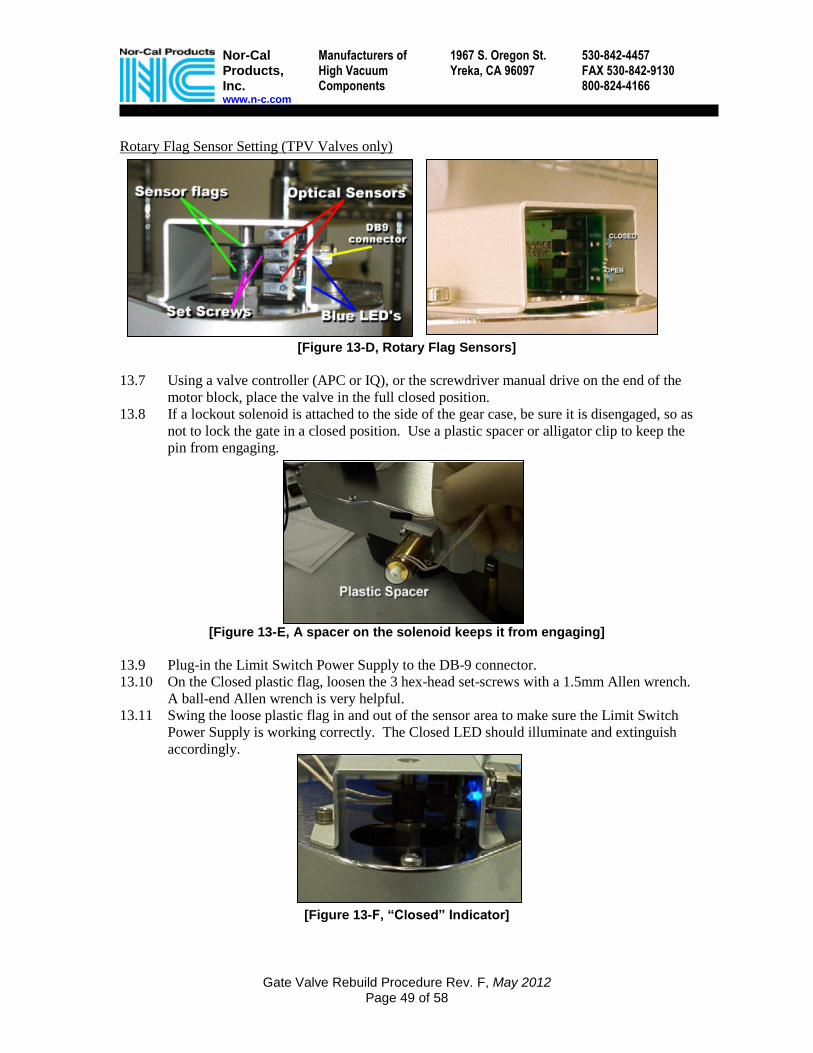
Rotary Flag Sensor Setting (TPV Valves only)
[Figure 13-D, Rotary Flag Sensors]
13.7 Using a valve controller (APC or IQ), or the screwdriver manual drive on the end of the
motor block, place the valve in the full closed position.
13.8 If a lockout solenoid is attached to the side of the gear case, be sure it is disengaged, so as
not to lock the gate in a closed position. Use a plastic spacer or alligator clip to keep the
pin from engaging.
[Figure 13-E, A spacer on the solenoid keeps it from engaging]
13.9 Plug-in the Limit Switch Power Supply to the DB-9 connector.
13.10 On the Closed plastic flag, loosen the 3 hex-head set-screws with a 1.5mm Allen wrench.
A ball-end Allen wrench is very helpful.
13.11 Swing the loose plastic flag in and out of the sensor area to make sure the Limit Switch
Power Supply is working correctly. The Closed LED should illuminate and extinguish
accordingly.
[Figure 13-F, “Closed” Indicator]

Nor-Cal Products, Inc. www.n-c.com
Manufacturers of High Vacuum Components
1967 S. Oregon St. Yreka, CA 96097
530-842-4457 FAX 530-842-9130 800-824-4166
Gate Valve Rebuild Procedure Rev. F, May 2012 Page 50 of 58
13.12 When you have verified that the power supply is connected correctly, and the valve is in
the full-closed position, simply adjust the flag such that it illuminates the top LED, and
gently tighten one of the set screws to hold it in place. Note that tightening the set screw
may shift the flag, so pay close attention.
13.13 Actuate the valve to the full-open position, and then return it to the full closed position.
Verify the proper “Closed” LED illuminates when the valve reaches the closed position.
Nor-Cal recommends the “Closed” indicator illuminate between 3% and 10% of valve
angle. A re-adjustment may be performed if it is not perfect the first time.
13.14 Once the “Closed” flag is fine-set as you require, tighten the remaining set-screws on the
“Closed” flag.
13.15 For the “Open” sensor flag, place the valve in the full open position, and adjust the
bottom flag in a similar manner.
[Figure 13-G, “Open” Indicator]
13.16 Nor-Cal recommends the “Open” indicator illuminate between 90% and 100% of valve
angle.
NOTE The rotary sensor flag Assembly is very sensitive to motion.
Removing the Case cover and replacing it may shift the position of the sensors, causing an inaccurate reading. Pay attention to the settings.
NOTE The rotary sensor flag Assembly can be upgraded to a Linear Sensor Assembly. However, the Linear Sensor Assembly only provides a “closed” indication, and
requires a new cover for the case to accommodate the assembly.

Nor-Cal Products, Inc. www.n-c.com
Manufacturers of High Vacuum Components
1967 S. Oregon St. Yreka, CA 96097
530-842-4457 FAX 530-842-9130 800-824-4166
Gate Valve Rebuild Procedure Rev. F, May 2012 Page 51 of 58
Section 14 Pneumatic Isolation Valve Sensors and Settings NOTE: The sensors are set at the factory, and unless they are bumped or damaged in the field, there is no need to adjust these sensors. However, if there is a problem in the field, a 9-Volt battery circuit is required to provide the proper voltage and current to the when positioning the sensors on the air cylinder: When the clip-leads are attached to the pins in the connector, the LED on this test circuit will illuminate when the sensor is activated. Alternately, a pre-fabricated 9V test fixture which connects directly to the AMP connector on the sensor leads is available from Nor-Cal Products: The procedure to set the position of the sensors is below.
470 Ohm
LED
Insulated Clips

Nor-Cal Products, Inc. www.n-c.com
Manufacturers of High Vacuum Components
1967 S. Oregon St. Yreka, CA 96097
530-842-4457 FAX 530-842-9130 800-824-4166
Gate Valve Rebuild Procedure Rev. F, May 2012 Page 52 of 58
14.1 Loosen the sensor attachment strap screws and leave the screws loose enough to slide the
sensors back and forth on the actuator.
14.2 Position the 2 sensors all the way at either end, one at the Case end, and the other at the
open end. (Fig 14-A)
[Figure 14-A, Move Sensors to the ends]
14.3 Apply air pressure to the pendulum valve, closing the gate.
[Figure 14-B, Attach the 9V test circuit to the connector]
14.4 Attach the 9V test circuit to pins 3 & 4 of the connector.
14.5 Slowly, slide the closed sensor toward the center of the actuator. (Fig. 14C) Stop sliding
the sensor when the LED on the 9V test circuit illuminates.
14.6 Tighten the strap screw at this position. Only the FIRST position is accurate.
14.7 Actuate the air solenoid, opening the valve’s gate. Move the test leads to pins 1 and 2.
14.8 Slowly, move the open sensor (nearest the gear box) towards the center of the actuator
until the LED on the 9V test circuit illuminates, and then tighten the strap screws.
[Figure 14-C, Push the sensor toward the center until the LED on the 9V test circuit illuminates]
Valve Closed Sensor (Actuator Shaft Retracted)
Valve Open Sensor (Actuator Shaft Extended)
470 Ohm
LED
Insulated Clips
Nor-Cal Products, Inc. www.n-c.com
Manufacturers of High Vacuum Components
1967 S. Oregon St. Yreka, CA 96097
530-842-4457 FAX 530-842-9130 800-824-4166
Gate Valve Rebuild Procedure Rev. F, May 2012 Page 53 of 58
US-Built, Nor-Cal Speed and Cushion Adjustment Procedure
CAUTION Caution must be used in attempting to increase valve cycle speed.
Forcing the valve to move faster can result in serious damage to internal components and affect the warranted performance.
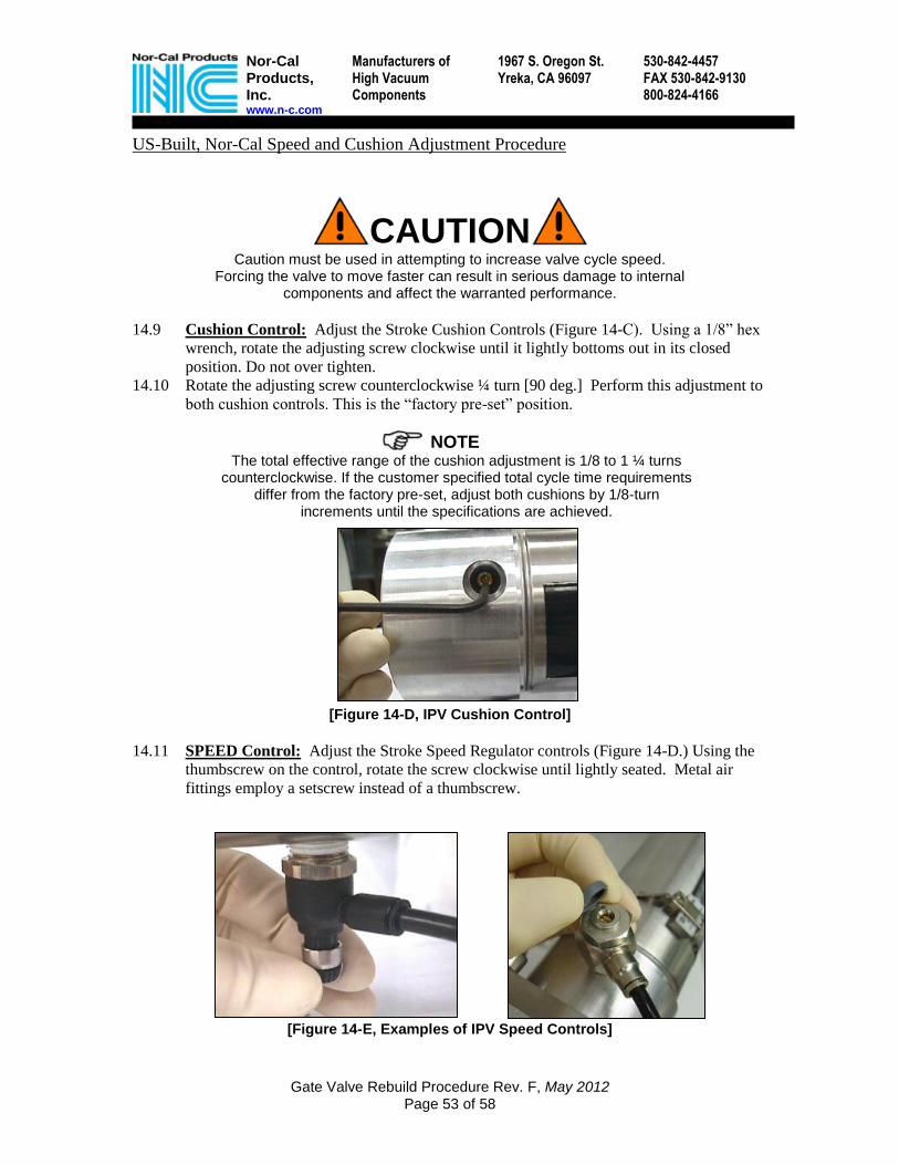
14.9 Cushion Control: Adjust the Stroke Cushion Controls (Figure 14-C). Using a 1/8” hex
wrench, rotate the adjusting screw clockwise until it lightly bottoms out in its closed
position. Do not over tighten.
14.10 Rotate the adjusting screw counterclockwise ¼ turn [90 deg.] Perform this adjustment to
both cushion controls. This is the “factory pre-set” position.
NOTE The total effective range of the cushion adjustment is 1/8 to 1 ¼ turns
counterclockwise. If the customer specified total cycle time requirements differ from the factory pre-set, adjust both cushions by 1/8-turn
increments until the specifications are achieved.
[Figure 14-D, IPV Cushion Control]
14.11 SPEED Control: Adjust the Stroke Speed Regulator controls (Figure 14-D.) Using the
thumbscrew on the control, rotate the screw clockwise until lightly seated. Metal air
fittings employ a setscrew instead of a thumbscrew.
[Figure 14-E, Examples of IPV Speed Controls]

Nor-Cal Products, Inc. www.n-c.com
Manufacturers of High Vacuum Components
1967 S. Oregon St. Yreka, CA 96097
530-842-4457 FAX 530-842-9130 800-824-4166
Gate Valve Rebuild Procedure Rev. F, May 2012 Page 54 of 58
[Figure 14-F, Adjustment locations and a graphical representation of control]
Open/Close Speed Green Closing speed is controlled by the outboard flow regulator on the end of the actuator.
Orange Opening speed is controlled by the inboard flow regulator closest to the gear case.
Cushion Controls Purple The area of cushion controlled while the valve is closing.
Blue The area of cushion controlled while the valve is opening.
NOTE Represented in the diagrams above are the cushion and flow regulator locations and the associated area of the stroke in which they control.
When adjusting them, consider that the open to close time and close to open time will greatly affect the setting of the cushion adjustments.
Opening Speed Control
Closing Speed Control
Opening Cushion Control
Closing Cushion Control
Open Close
DANGER! Do not rest hands on
or near the Gate
Flange opening

Nor-Cal Products, Inc. www.n-c.com
Manufacturers of High Vacuum Components
1967 S. Oregon St. Yreka, CA 96097
530-842-4457 FAX 530-842-9130 800-824-4166
Gate Valve Rebuild Procedure Rev. F, May 2012 Page 55 of 58
Appendix A Spare Parts
[Figure A-1, Spare Part Kits Photos (examples only)]
Photos of Spares & Kits NOTE: Spares Kit photos are examples only.
Kits for specific valve configurations may vary accordingly
220000mmmm HHaarrdd SSttoopp

Nor-Cal Products, Inc. www.n-c.com
Manufacturers of High Vacuum Components
1967 S. Oregon St. Yreka, CA 96097
530-842-4457 FAX 530-842-9130 800-824-4166
Gate Valve Rebuild Procedure Rev. F, May 2012 Page 56 of 58
NOTE
Nor-Cal defines the valve size by the main bore opening, not by the size of wafer processed in the tool. Please refer to the part number for confirmation.
350mm Pendulum Valves 350mm Kits 350mm Nor-Cal Valves
350 Crash Kit 72-00054
350 Seal Kit * 72-00055
350 Spring Kit 72-00023
350 Gate Assembly 72-00024
350 Drive Kit IPV-00998-950
350 Gate Kit 72-00034
350 Poly Pad Kit IPV-350-40
350 Case Kit 070226-2
350 Bolt Hardware Kit 72-00022
350 Gate Arm 56-05037
350 Air Control Assembly Kit 56-05084
350 Bonnet 56-05007
350 Hard Stop (1-piece) 72-00035
350 Hard Stop (2-piece) 72-00037
350 Hard Stop (3-piece) 72-00038
350 Gate Support (all 3-pieces) 72-00036
350 IPV Open/Close Sensors (set of 2) 72-00059
350 Gate Plate, (Plate only, for E38 o-ring) 56-05012
350 Gate Plate, (Plate only, for 4079 o-ring) 040404-2-01A
350 Power Bolt 56-05058
350 Gate Arm Shaft (includes key) 72-00061
350 Gate Arm Height Gauge 020602-02
Pendulum Valve Tool Kit PENDULUM VALVE TOOL KIT
* All O-rings are also available separately from the Seal Kit.

Nor-Cal Products, Inc. www.n-c.com
Manufacturers of High Vacuum Components
1967 S. Oregon St. Yreka, CA 96097
530-842-4457 FAX 530-842-9130 800-824-4166
Gate Valve Rebuild Procedure Rev. F, May 2012 Page 57 of 58
250mm Pendulum Valves
250mm Kits 250mm Nor-Cal Valves
250 Crash Kit 72-00003
250 Seal Kit * 72-00004
250 Spring Kit 72-00009
250 Gate Assembly 56-03071
250 Drive Kit 72-00007
250 Gate Kit 72-00343
250 Poly Pad Kit 72-00002
250 Case Kit 72-00001
250 Bolt Hardware Kit 72-00008
250 Gate Arm, 14.8 degree 56-03051
250 Air Control Assembly Kit 72-00042
250 Bonnet 72-00046
250 Hard Stop (1-piece) 72-00013
250 Hard Stop (2-piece) 72-00070
250 Hard Stop (3-piece) 56-03097
250 Gate Support 72-00047
250 IPV Open/Close Sensors (set of 2) 72-00062
250 TPV Linear “Closed” sensor 72-00006
250 Gate Plate (plate only) 72-00042
250 Power Bolt 72-00012
250 Gate Arm Shaft (includes key) 72-00014
250 Gate Arm Height Gauge 020602-1
250 Air Cylinder & Perfect Block Kit 72-00011
Pendulum Valve Tool Kit PENDULUM VALVE TOOL KIT
* All O-rings are also available separately from the Seal Kit.

Nor-Cal Products, Inc. www.n-c.com
Manufacturers of High Vacuum Components
1967 S. Oregon St. Yreka, CA 96097
530-842-4457 FAX 530-842-9130 800-824-4166
Gate Valve Rebuild Procedure Rev. F, May 2012 Page 58 of 58
200mm Pendulum Valves NOTE: Items with 1 part number are identical for Standard and Symmetrical valves
200mm Kits 200mm Standard Valves 200mm Symmetrical Valves
200 Crash Kit 72-00033
200 Seal Kit * 72-00063
200 Spring Kit 72-00064
200 Gate Assembly 56-02060 56-02061
200 Drive Kit 72-00020 72-00068
200 Gate Kit 72-00065
200 Poly Pad Kit 72-00066
200 Case Kit 72-00069 72-00067
200 Hard Stop 56-00022
200 TPV Rotary Open/Close Sensors 56-00023
200 TPV Linear “Closed” sensor 72-00010 72-00015
200 Power Bolt 56-02055
200 Gate Arm Height Gauge 020929-1
Pendulum Valve Tool Kit PENDULUM VALVE TOOL KIT
* All O-rings are also available separately from the Seal Kit.