
PEM Europe Introduction - pemnet.com angle fasteners that are encased into the monitor plastic. A...
66
© 2014 www.pemnet.com 1 iPhone 6 2015-Feb-19 by MJM PennEngineering ®
Transcript of PEM Europe Introduction - pemnet.com angle fasteners that are encased into the monitor plastic. A...

© 2014 www.pemnet.com 1
iPhone 6
2015-Feb-19
by MJM
PennEngineering®
Title Slide – Do Not Remove Enter the Name and Model of the object being torn down.
If it is CSI, leave the Confidential note.
If it is a teardown, remove the confidential note, delete the CSI logo.

© 2014 www.pemnet.com 2
iPhone 6
Introductory Slide – Do Not Remove Enter the name of the object being torn down
and a picture of the assembled product.

© 2014 www.pemnet.com 3
Details & Findings
Pictures and Description of the
iPhone 6 and our disassembly
process.
Section Heading Slide – Do Not Remove Enter the Name of the object being torn down.
© 2014 www.pemnet.com 4
Detaching the Screen
Detail Slide – Copy and use for details. Title various slides to correspond with different
portions of the object being torn down (e.g.
Case, charging station, etc…)
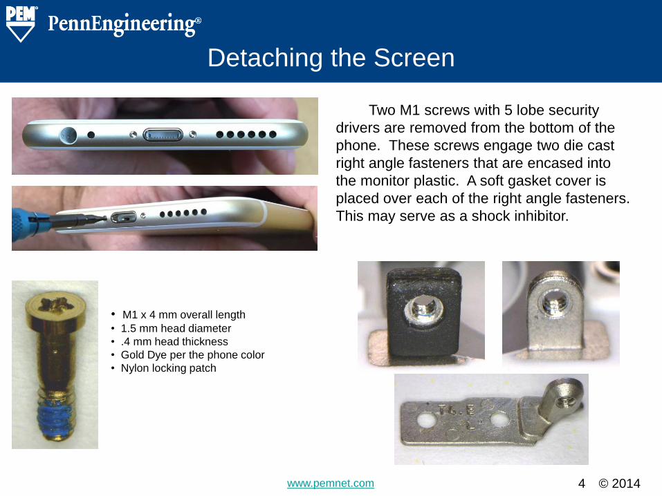
• M1 x 4 mm overall length
• 1.5 mm head diameter
• .4 mm head thickness
• Gold Dye per the phone color
• Nylon locking patch
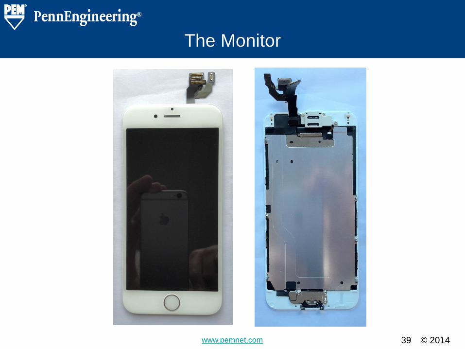
Two M1 screws with 5 lobe security
drivers are removed from the bottom of the
phone. These screws engage two die cast
right angle fasteners that are encased into
the monitor plastic. A soft gasket cover is
placed over each of the right angle fasteners.
This may serve as a shock inhibitor.
© 2014 www.pemnet.com
Detaching the Screen
5
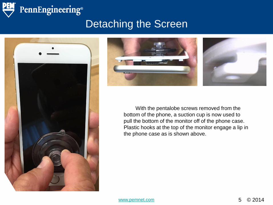
With the pentalobe screws removed from the
bottom of the phone, a suction cup is now used to
pull the bottom of the monitor off of the phone case.
Plastic hooks at the top of the monitor engage a lip in
the phone case as is shown above.
© 2014 www.pemnet.com
Detaching the Screen
6
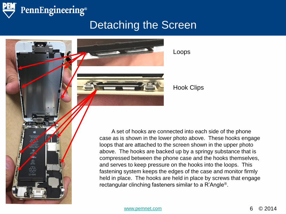
A set of hooks are connected into each side of the phone
case as is shown in the lower photo above. These hooks engage
loops that are attached to the screen shown in the upper photo
above. The hooks are backed up by a springy substance that is
compressed between the phone case and the hooks themselves,
and serves to keep pressure on the hooks into the loops. This
fastening system keeps the edges of the case and monitor firmly
held in place. The hooks are held in place by screws that engage
rectangular clinching fasteners similar to a R’Angle®.
Loops
Hook Clips
© 2014 www.pemnet.com
Detaching the Screen
7
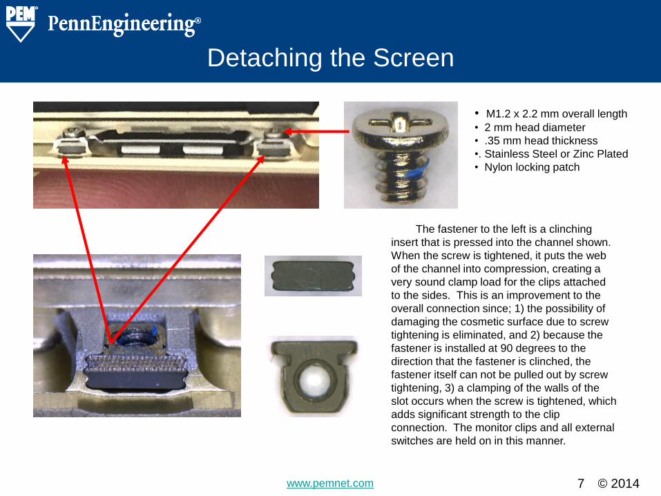
• M1.2 x 2.2 mm overall length
• 2 mm head diameter
• .35 mm head thickness
•. Stainless Steel or Zinc Plated
• Nylon locking patch
The fastener to the left is a clinching
insert that is pressed into the channel shown.
When the screw is tightened, it puts the web
of the channel into compression, creating a
very sound clamp load for the clips attached
to the sides. This is an improvement to the
overall connection since; 1) the possibility of
damaging the cosmetic surface due to screw
tightening is eliminated, and 2) because the
fastener is installed at 90 degrees to the
direction that the fastener is clinched, the
fastener itself can not be pulled out by screw
tightening, 3) a clamping of the walls of the
slot occurs when the screw is tightened, which
adds significant strength to the clip
connection. The monitor clips and all external
switches are held on in this manner.
© 2014 www.pemnet.com
Disconnecting the Screen Ribbons
8
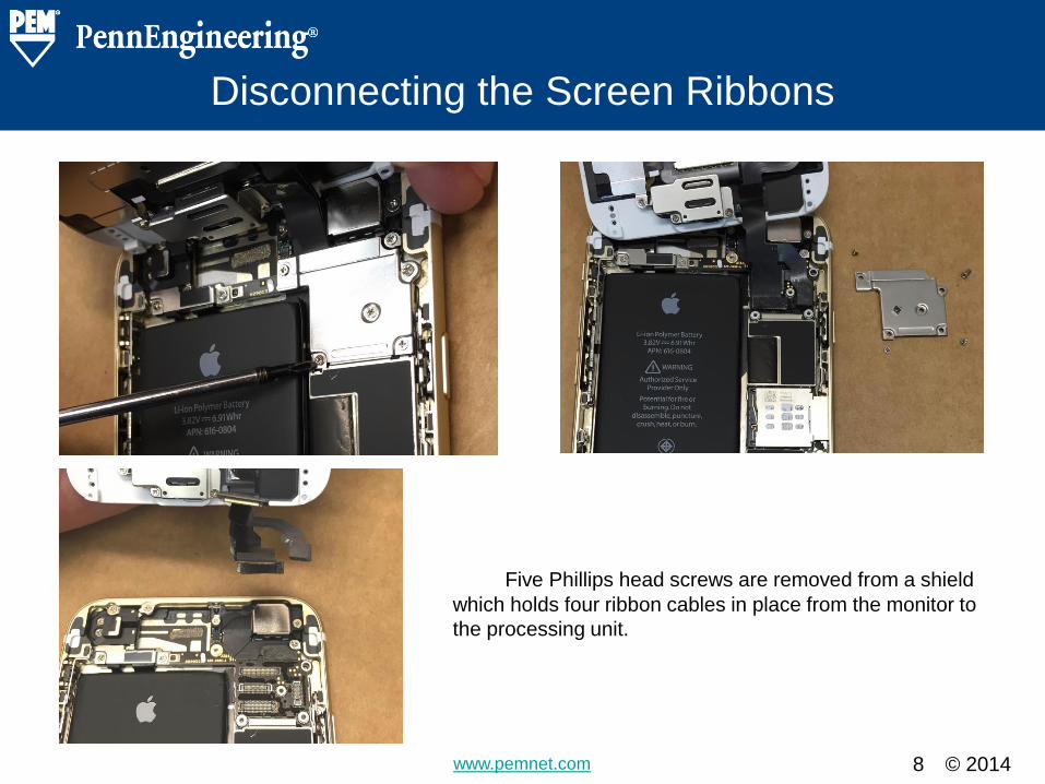
Five Phillips head screws are removed from a shield
which holds four ribbon cables in place from the monitor to
the processing unit.
© 2014 www.pemnet.com
Disconnecting the Screen Ribbons
9
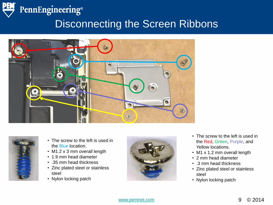
• The screw to the left is used in
the Red, Green, Purple, and
Yellow locations.
• M1 x 1.2 mm overall length
• 2 mm head diameter
• .3 mm head thickness
• Zinc plated steel or stainless
steel
• Nylon locking patch
• The screw to the left is used in
the Blue location.
• M1.2 x 3 mm overall length
• 1.9 mm head diameter
• .35 mm head thickness
• Zinc plated steel or stainless
steel
• Nylon locking patch
© 2014 www.pemnet.com
Disconnecting the Screen Ribbons
10
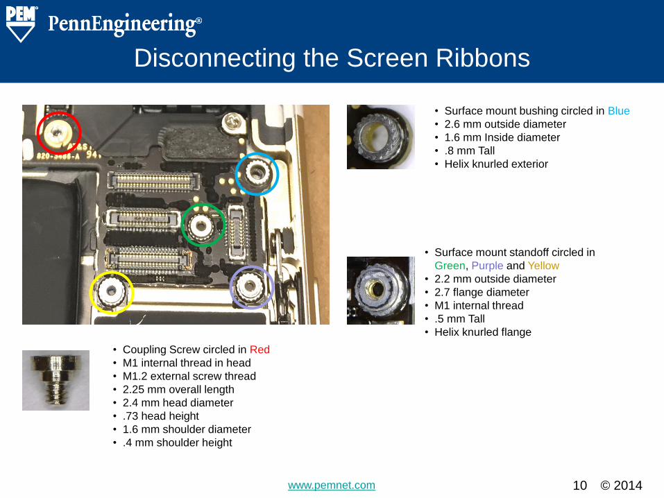
• Surface mount bushing circled in Blue
• 2.6 mm outside diameter
• 1.6 mm Inside diameter
• .8 mm Tall
• Helix knurled exterior
• Surface mount standoff circled in
Green, Purple and Yellow
• 2.2 mm outside diameter
• 2.7 flange diameter
• M1 internal thread
• .5 mm Tall
• Helix knurled flange
• Coupling Screw circled in Red
• M1 internal thread in head
• M1.2 external screw thread
• 2.25 mm overall length
• 2.4 mm head diameter
• .73 head height
• 1.6 mm shoulder diameter
• .4 mm shoulder height
© 2014 www.pemnet.com
Disconnecting the Screen Ribbons
11
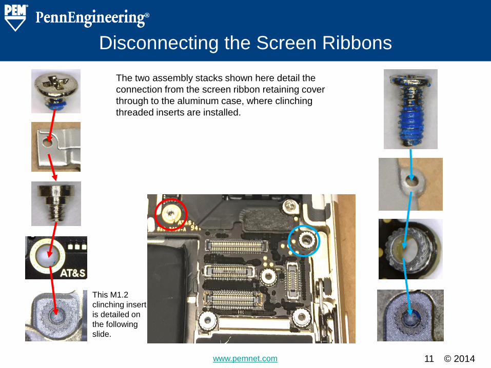
The two assembly stacks shown here detail the
connection from the screen ribbon retaining cover
through to the aluminum case, where clinching
threaded inserts are installed.
This M1.2
clinching insert
is detailed on
the following
slide.
© 2014 www.pemnet.com
The M1.2 Clinching Threaded Insert
12
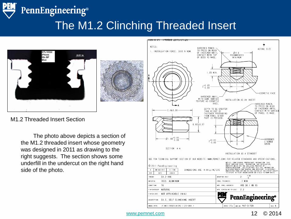
M1.2 Threaded Insert Section
The photo above depicts a section of
the M1.2 threaded insert whose geometry
was designed in 2011 as drawing to the
right suggests. The section shows some
underfill in the undercut on the right hand
side of the photo.
© 2014 www.pemnet.com
Disconnecting the Battery
13
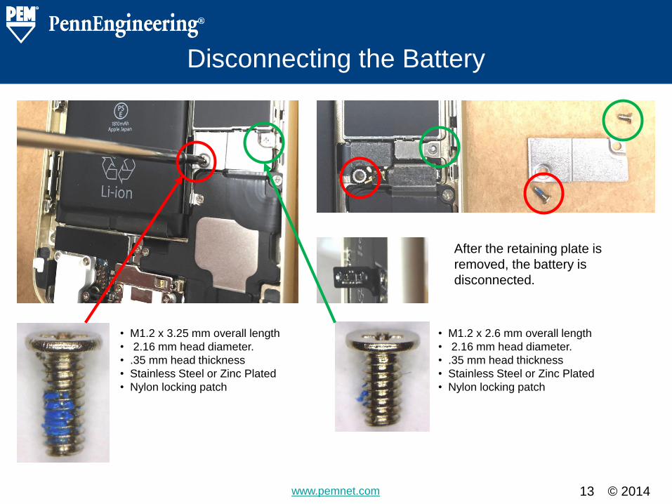
• M1.2 x 3.25 mm overall length
• 2.16 mm head diameter.
• .35 mm head thickness
• Stainless Steel or Zinc Plated
• Nylon locking patch
• M1.2 x 2.6 mm overall length
• 2.16 mm head diameter.
• .35 mm head thickness
• Stainless Steel or Zinc Plated
• Nylon locking patch
After the retaining plate is
removed, the battery is
disconnected.
© 2014 www.pemnet.com
Disconnecting the Battery
14
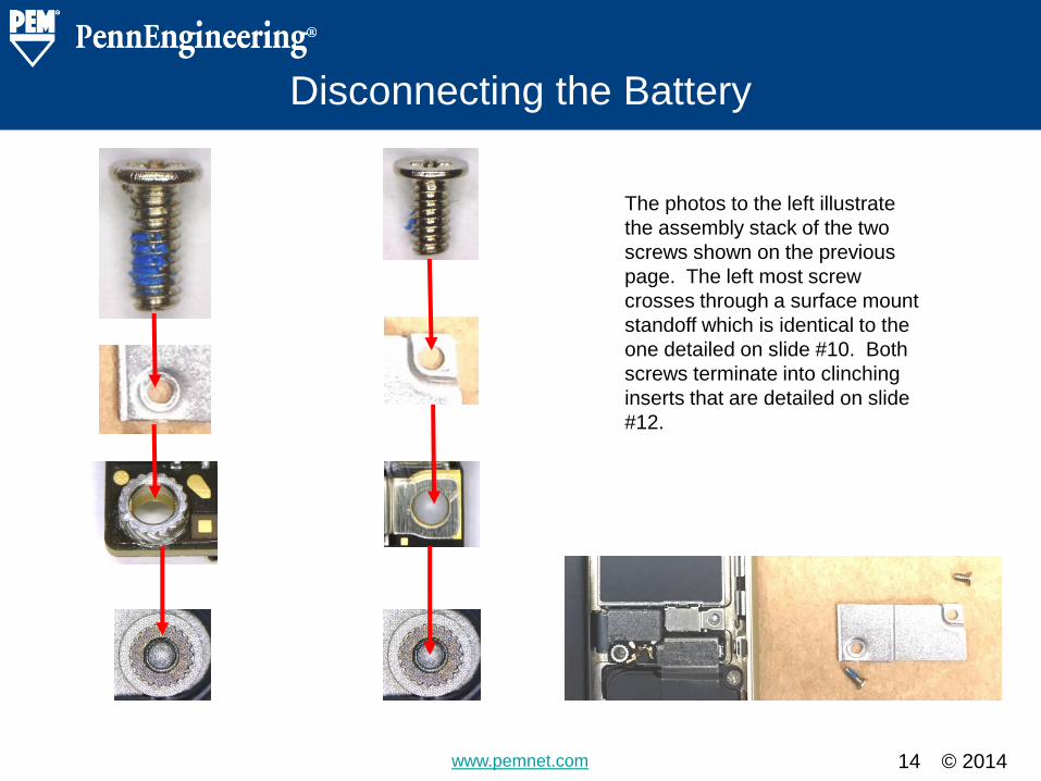
The photos to the left illustrate
the assembly stack of the two
screws shown on the previous
page. The left most screw
crosses through a surface mount
standoff which is identical to the
one detailed on slide #10. Both
screws terminate into clinching
inserts that are detailed on slide
#12.
© 2014 www.pemnet.com
Disconnecting the Battery
15
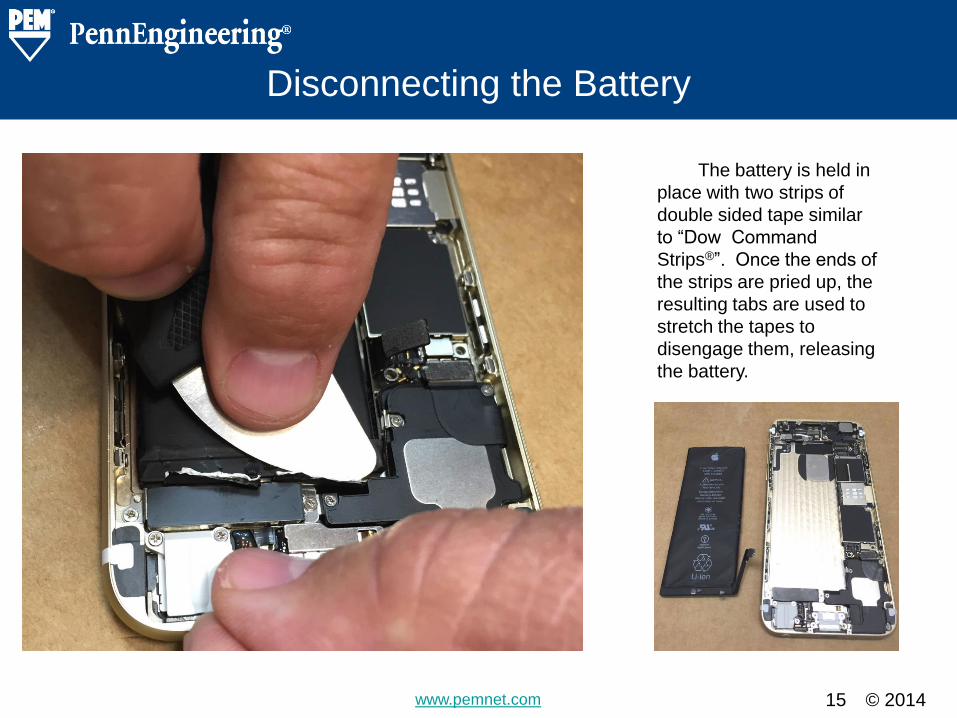
The battery is held in
place with two strips of
double sided tape similar
to “Dow Command
Strips®”. Once the ends of
the strips are pried up, the
resulting tabs are used to
stretch the tapes to
disengage them, releasing
the battery.
© 2014 www.pemnet.com
Removing The Camera
16
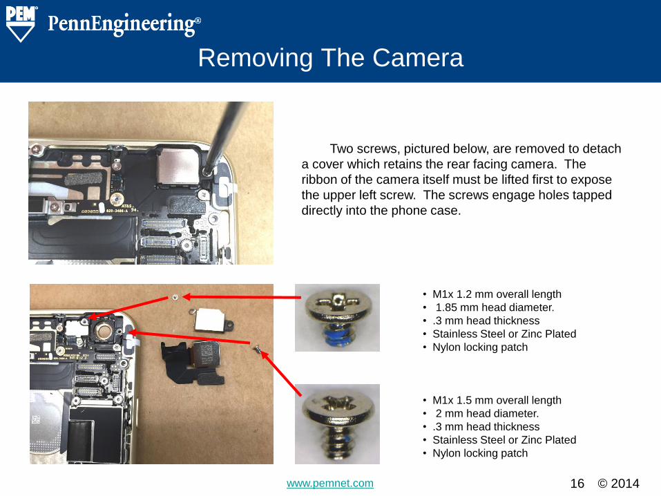
• M1x 1.2 mm overall length
• 1.85 mm head diameter.
• .3 mm head thickness
• Stainless Steel or Zinc Plated
• Nylon locking patch
• M1x 1.5 mm overall length
• 2 mm head diameter.
• .3 mm head thickness
• Stainless Steel or Zinc Plated
• Nylon locking patch
Two screws, pictured below, are removed to detach
a cover which retains the rear facing camera. The
ribbon of the camera itself must be lifted first to expose
the upper left screw. The screws engage holes tapped
directly into the phone case.
© 2014 www.pemnet.com
Small Ribbon Connector under Camera
17
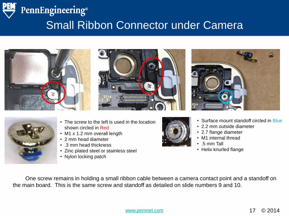
• The screw to the left is used in the location
shown circled in Red
• M1 x 1.2 mm overall length
• 2 mm head diameter
• .3 mm head thickness
• Zinc plated steel or stainless steel
• Nylon locking patch
• Surface mount standoff circled in Blue
• 2.2 mm outside diameter
• 2.7 flange diameter
• M1 internal thread
• .5 mm Tall
• Helix knurled flange
One screw remains in holding a small ribbon cable between a camera contact point and a standoff on
the main board. This is the same screw and standoff as detailed on slide numbers 9 and 10.
© 2014 www.pemnet.com
The Flash Retaining Shield
18
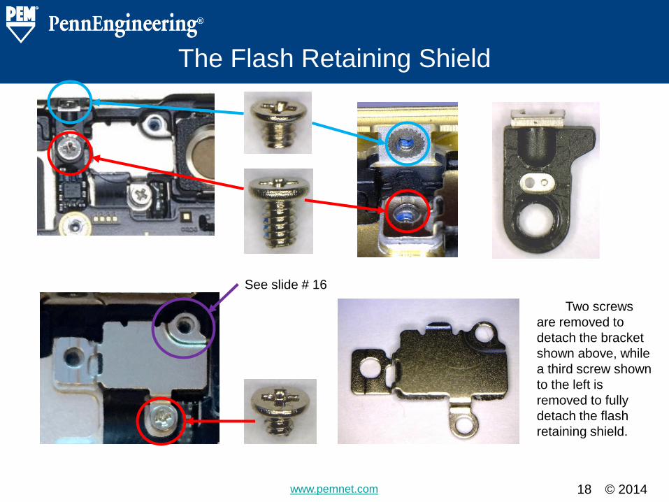
Two screws
are removed to
detach the bracket
shown above, while
a third screw shown
to the left is
removed to fully
detach the flash
retaining shield.
See slide # 16
© 2014 www.pemnet.com
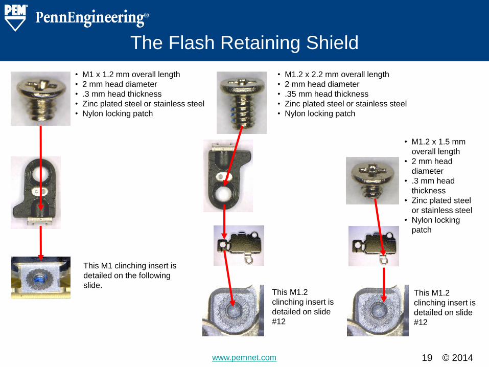
The Flash Retaining Shield
19
• M1 x 1.2 mm overall length
• 2 mm head diameter
• .3 mm head thickness
• Zinc plated steel or stainless steel
• Nylon locking patch
• M1.2 x 2.2 mm overall length
• 2 mm head diameter
• .35 mm head thickness
• Zinc plated steel or stainless steel
• Nylon locking patch
This M1 clinching insert is
detailed on the following
slide. This M1.2
clinching insert is
detailed on slide
#12
This M1.2
clinching insert is
detailed on slide
#12
• M1.2 x 1.5 mm
overall length
• 2 mm head
diameter
• .3 mm head
thickness
• Zinc plated steel
or stainless steel
• Nylon locking
patch
© 2014 www.pemnet.com
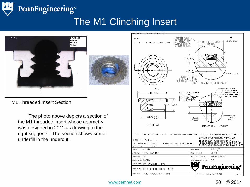
The M1 Clinching Insert
20
The photo above depicts a section of
the M1 threaded insert whose geometry
was designed in 2011 as drawing to the
right suggests. The section shows some
underfill in the undercut.
M1 Threaded Insert Section
© 2014 www.pemnet.com
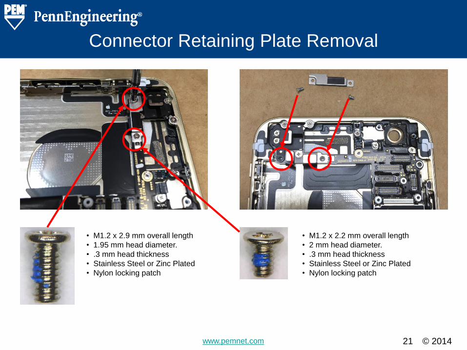
Connector Retaining Plate Removal
21
• M1.2 x 2.9 mm overall length
• 1.95 mm head diameter.
• .3 mm head thickness
• Stainless Steel or Zinc Plated
• Nylon locking patch
• M1.2 x 2.2 mm overall length
• 2 mm head diameter.
• .3 mm head thickness
• Stainless Steel or Zinc Plated
• Nylon locking patch
© 2014 www.pemnet.com
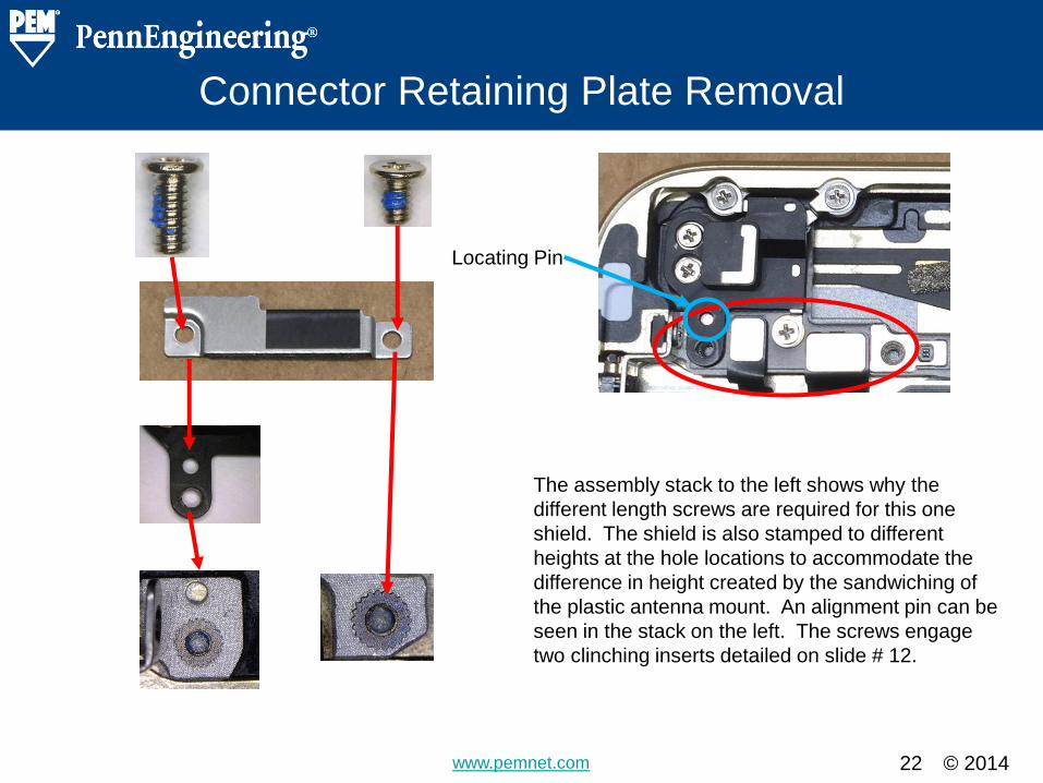
Connector Retaining Plate Removal
22
The assembly stack to the left shows why the
different length screws are required for this one
shield. The shield is also stamped to different
heights at the hole locations to accommodate the
difference in height created by the sandwiching of
the plastic antenna mount. An alignment pin can be
seen in the stack on the left. The screws engage
two clinching inserts detailed on slide # 12.
Locating Pin
© 2014 www.pemnet.com
The Antenna
23
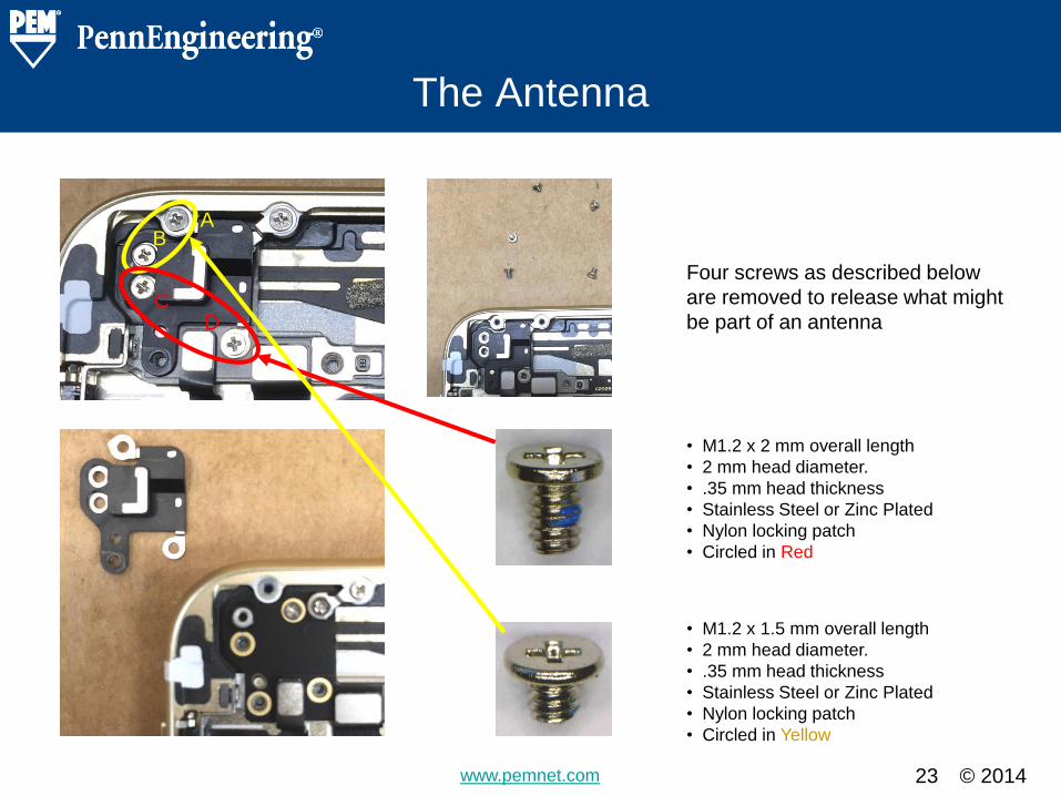
• M1.2 x 2 mm overall length
• 2 mm head diameter.
• .35 mm head thickness
• Stainless Steel or Zinc Plated
• Nylon locking patch
• Circled in Red
• M1.2 x 1.5 mm overall length
• 2 mm head diameter.
• .35 mm head thickness
• Stainless Steel or Zinc Plated
• Nylon locking patch
• Circled in Yellow
Four screws as described below
are removed to release what might
be part of an antenna
A B
C D
© 2014 www.pemnet.com
The Antenna
24
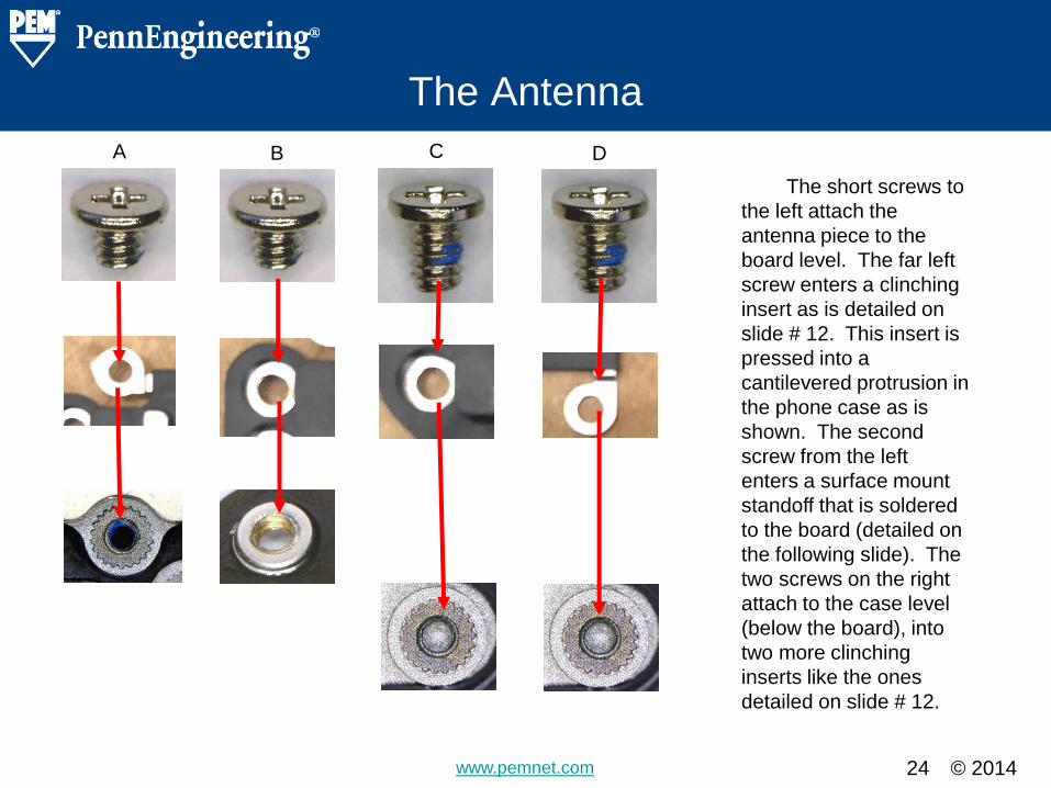
The short screws to
the left attach the
antenna piece to the
board level. The far left
screw enters a clinching
insert as is detailed on
slide # 12. This insert is
pressed into a
cantilevered protrusion in
the phone case as is
shown. The second
screw from the left
enters a surface mount
standoff that is soldered
to the board (detailed on
the following slide). The
two screws on the right
attach to the case level
(below the board), into
two more clinching
inserts like the ones
detailed on slide # 12.
A B C D
© 2014 www.pemnet.com
The Antenna
25
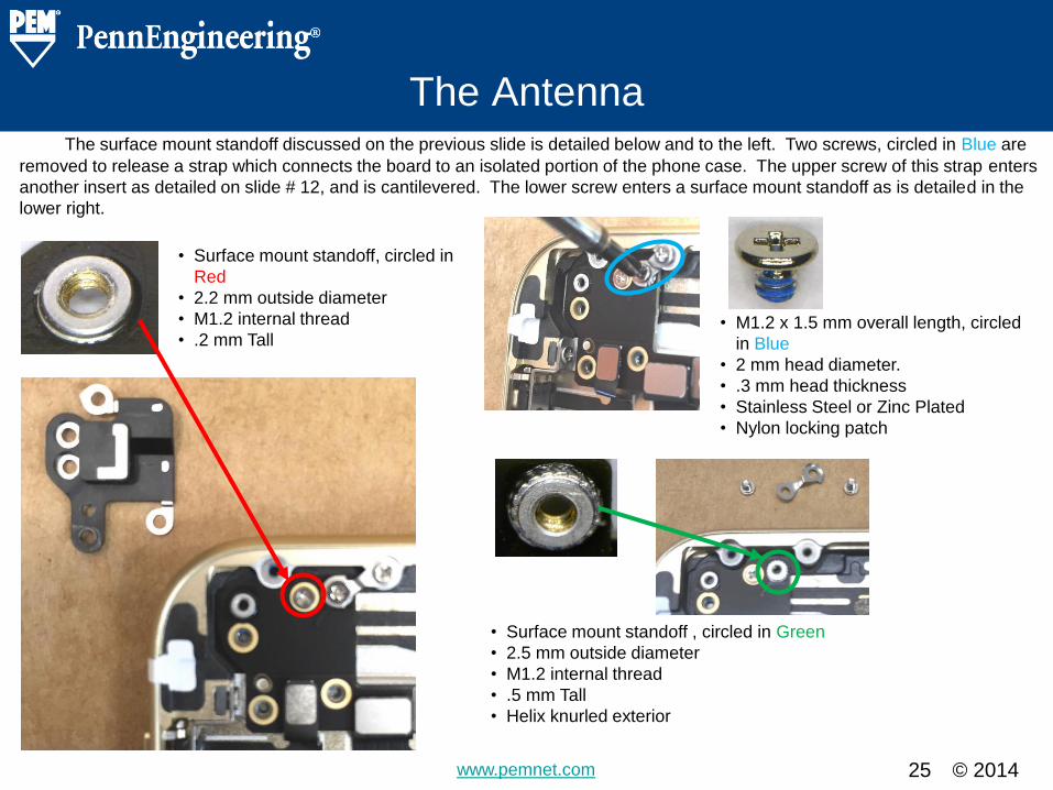
• Surface mount standoff, circled in
Red
• 2.2 mm outside diameter
• M1.2 internal thread
• .2 mm Tall
• Surface mount standoff , circled in Green
• 2.5 mm outside diameter
• M1.2 internal thread
• .5 mm Tall
• Helix knurled exterior
• M1.2 x 1.5 mm overall length, circled
in Blue
• 2 mm head diameter.
• .3 mm head thickness
• Stainless Steel or Zinc Plated
• Nylon locking patch
The surface mount standoff discussed on the previous slide is detailed below and to the left. Two screws, circled in Blue are
removed to release a strap which connects the board to an isolated portion of the phone case. The upper screw of this strap enters
another insert as detailed on slide # 12, and is cantilevered. The lower screw enters a surface mount standoff as is detailed in the
lower right.
© 2014 www.pemnet.com
More Antenna
26
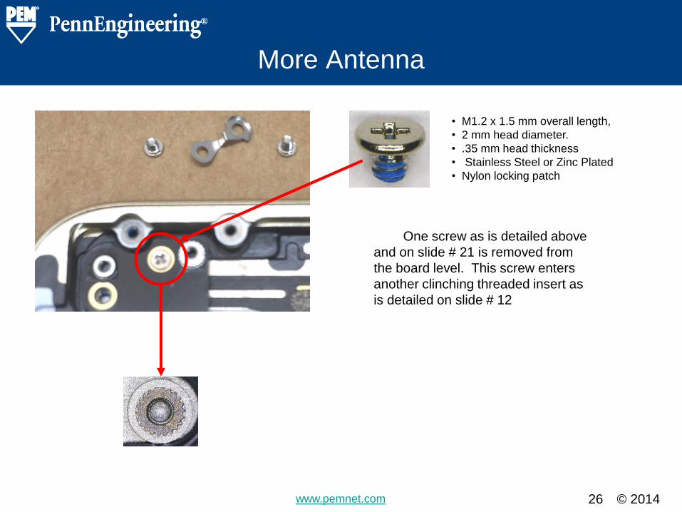
• M1.2 x 1.5 mm overall length,
• 2 mm head diameter.
• .35 mm head thickness
• Stainless Steel or Zinc Plated
• Nylon locking patch
One screw as is detailed above
and on slide # 21 is removed from
the board level. This screw enters
another clinching threaded insert as
is detailed on slide # 12
© 2014 www.pemnet.com
Board Locating Connection
27
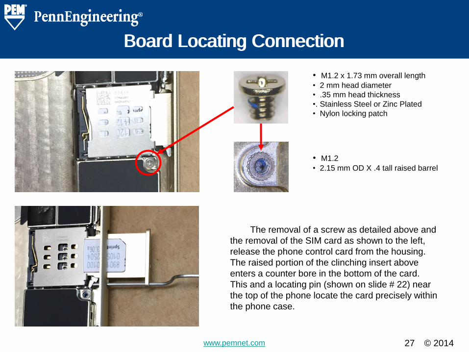
• M1.2 x 1.73 mm overall length
• 2 mm head diameter
• .35 mm head thickness
•. Stainless Steel or Zinc Plated
• Nylon locking patch
Board Locating Connection
• M1.2
• 2.15 mm OD X .4 tall raised barrel
The removal of a screw as detailed above and
the removal of the SIM card as shown to the left,
release the phone control card from the housing.
The raised portion of the clinching insert above
enters a counter bore in the bottom of the card.
This and a locating pin (shown on slide # 22) near
the top of the phone locate the card precisely within
the phone case.
© 2014 www.pemnet.com
The M1.2 Locating Insert
28
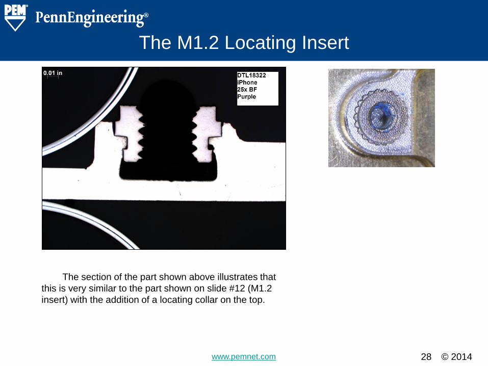
The section of the part shown above illustrates that
this is very similar to the part shown on slide #12 (M1.2
insert) with the addition of a locating collar on the top.
© 2014 www.pemnet.com
The SIM Card Ejector
29
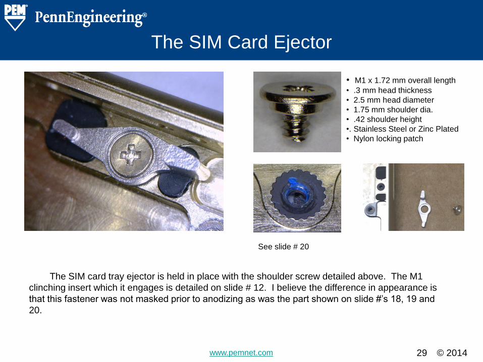
• M1 x 1.72 mm overall length
• .3 mm head thickness
• 2.5 mm head diameter
• 1.75 mm shoulder dia.
• .42 shoulder height
•. Stainless Steel or Zinc Plated
• Nylon locking patch
See slide # 20
The SIM card tray ejector is held in place with the shoulder screw detailed above. The M1
clinching insert which it engages is detailed on slide # 12. I believe the difference in appearance is
that this fastener was not masked prior to anodizing as was the part shown on slide #’s 18, 19 and
20.
© 2014 www.pemnet.com
The Vibrate Motor
30
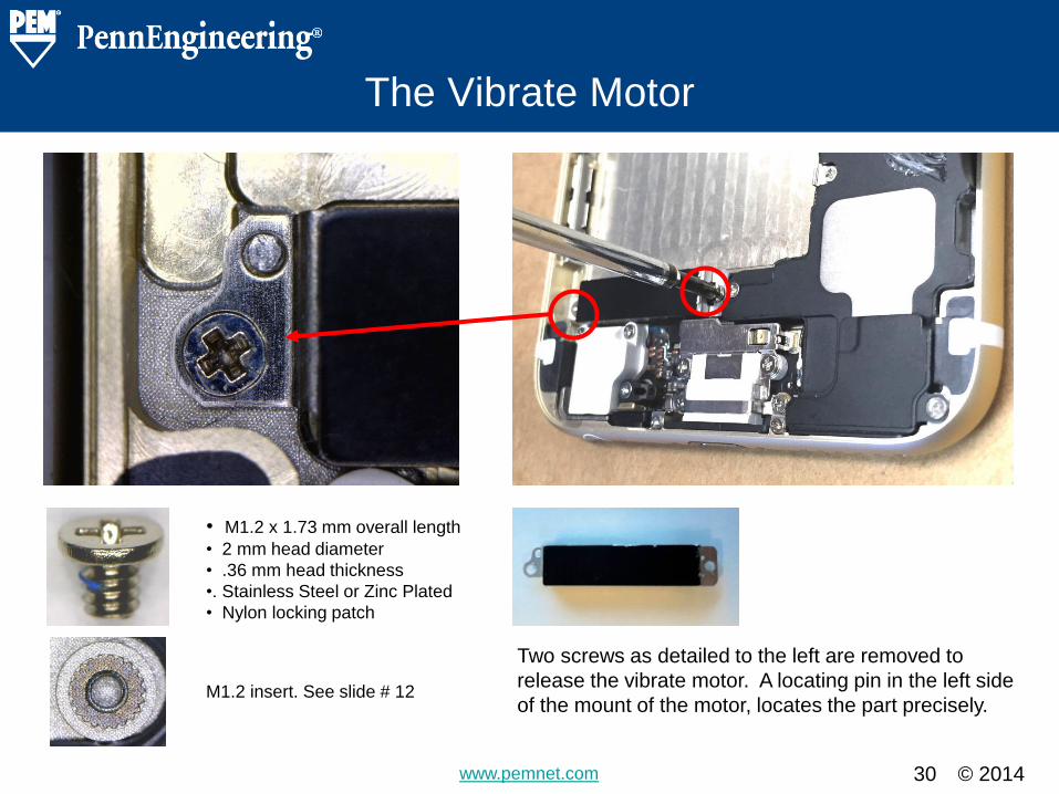
• M1.2 x 1.73 mm overall length
• 2 mm head diameter
• .36 mm head thickness
•. Stainless Steel or Zinc Plated
• Nylon locking patch
M1.2 insert. See slide # 12
Two screws as detailed to the left are removed to
release the vibrate motor. A locating pin in the left side
of the mount of the motor, locates the part precisely.
© 2014 www.pemnet.com
The Big Speaker
31
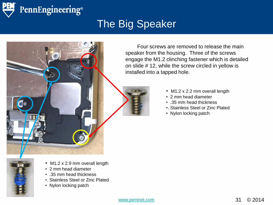
• M1.2 x 2.9 mm overall length
• 2 mm head diameter
• .35 mm head thickness
•. Stainless Steel or Zinc Plated
• Nylon locking patch
• M1.2 x 2.2 mm overall length
• 2 mm head diameter
• .35 mm head thickness
•. Stainless Steel or Zinc Plated
• Nylon locking patch
Four screws are removed to release the main
speaker from the housing. Three of the screws
engage the M1.2 clinching fastener which is detailed
on slide # 12, while the screw circled in yellow is
installed into a tapped hole.
© 2014 www.pemnet.com
Some Antenna Connections
32
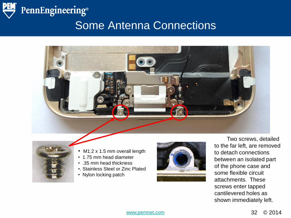
• M1.2 x 1.5 mm overall length
• 1.75 mm head diameter
• .35 mm head thickness
•. Stainless Steel or Zinc Plated
• Nylon locking patch
Two screws, detailed
to the far left, are removed
to detach connections
between an isolated part
of the phone case and
some flexible circuit
attachments. These
screws enter tapped
cantilevered holes as
shown immediately left.
© 2014 www.pemnet.com
The Data / Charging Port
33
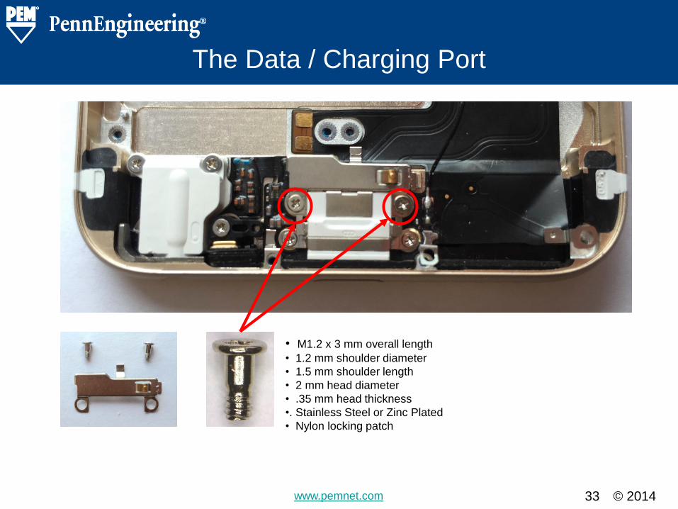
• M1.2 x 3 mm overall length
• 1.2 mm shoulder diameter
• 1.5 mm shoulder length
• 2 mm head diameter
• .35 mm head thickness
•. Stainless Steel or Zinc Plated
• Nylon locking patch
© 2014 www.pemnet.com
The Data / Charging Port
34
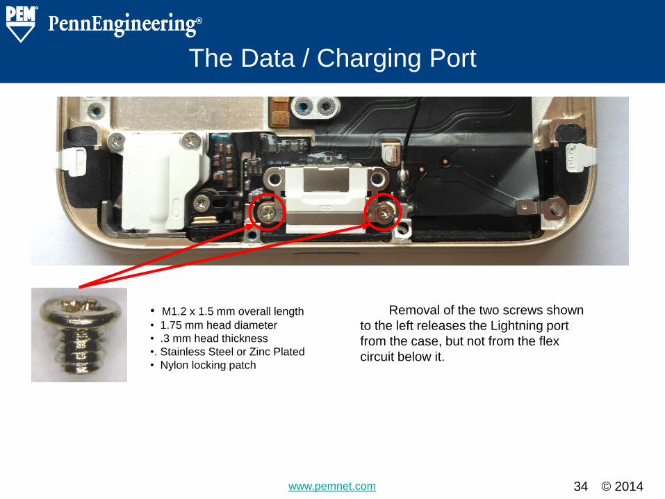
• M1.2 x 1.5 mm overall length
• 1.75 mm head diameter
• .3 mm head thickness
•. Stainless Steel or Zinc Plated
• Nylon locking patch
Removal of the two screws shown
to the left releases the Lightning port
from the case, but not from the flex
circuit below it.
© 2014 www.pemnet.com
Small Speaker Backer
35
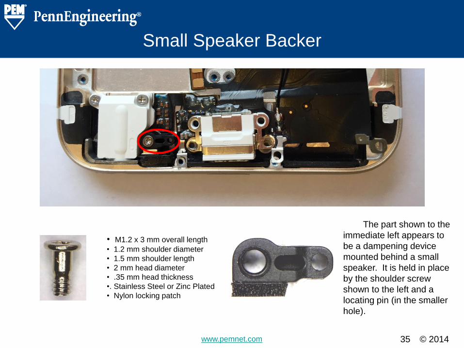
• M1.2 x 3 mm overall length
• 1.2 mm shoulder diameter
• 1.5 mm shoulder length
• 2 mm head diameter
• .35 mm head thickness
•. Stainless Steel or Zinc Plated
• Nylon locking patch
The part shown to the
immediate left appears to
be a dampening device
mounted behind a small
speaker. It is held in place
by the shoulder screw
shown to the left and a
locating pin (in the smaller
hole).
© 2014 www.pemnet.com
The Earphone Jack
36
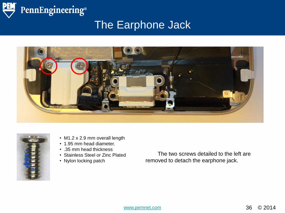
• M1.2 x 2.9 mm overall length
• 1.95 mm head diameter.
• .35 mm head thickness
• Stainless Steel or Zinc Plated
• Nylon locking patch
The two screws detailed to the left are
removed to detach the earphone jack.
© 2014 www.pemnet.com
The Phone Case
37
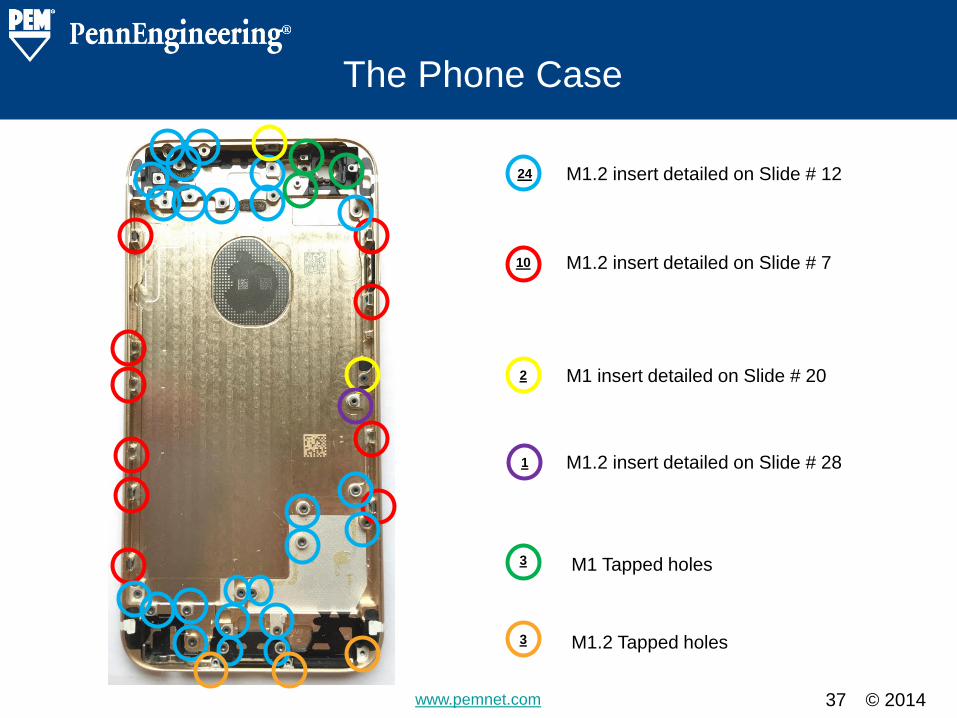
10
24
2
1
3
M1.2 insert detailed on Slide # 12
M1.2 insert detailed on Slide # 7
M1 insert detailed on Slide # 20
M1.2 insert detailed on Slide # 28
M1 Tapped holes
3 M1.2 Tapped holes
© 2014 www.pemnet.com
The Phone Board
38
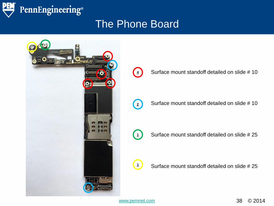
1
1
2
4 Surface mount standoff detailed on slide # 10
Surface mount standoff detailed on slide # 10
Surface mount standoff detailed on slide # 25
Surface mount standoff detailed on slide # 25
© 2014 www.pemnet.com
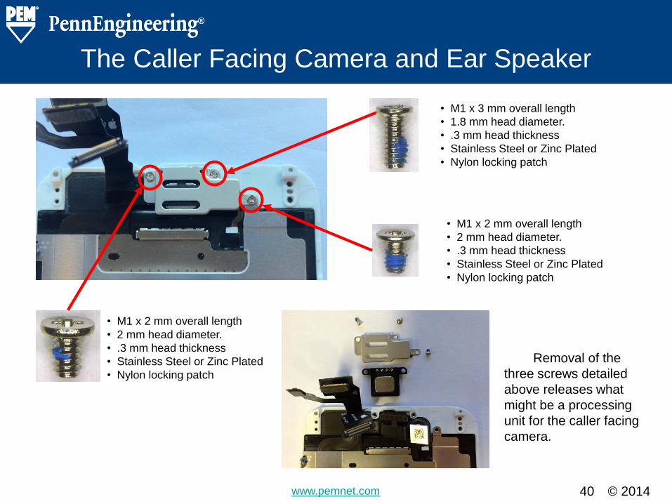
The Caller Facing Camera and Ear Speaker
40
• M1 x 2 mm overall length
• 2 mm head diameter.
• .3 mm head thickness
• Stainless Steel or Zinc Plated
• Nylon locking patch
• M1 x 3 mm overall length
• 1.8 mm head diameter.
• .3 mm head thickness
• Stainless Steel or Zinc Plated
• Nylon locking patch
• M1 x 2 mm overall length
• 2 mm head diameter.
• .3 mm head thickness
• Stainless Steel or Zinc Plated
• Nylon locking patch
Removal of the
three screws detailed
above releases what
might be a processing
unit for the caller facing
camera.
© 2014 www.pemnet.com
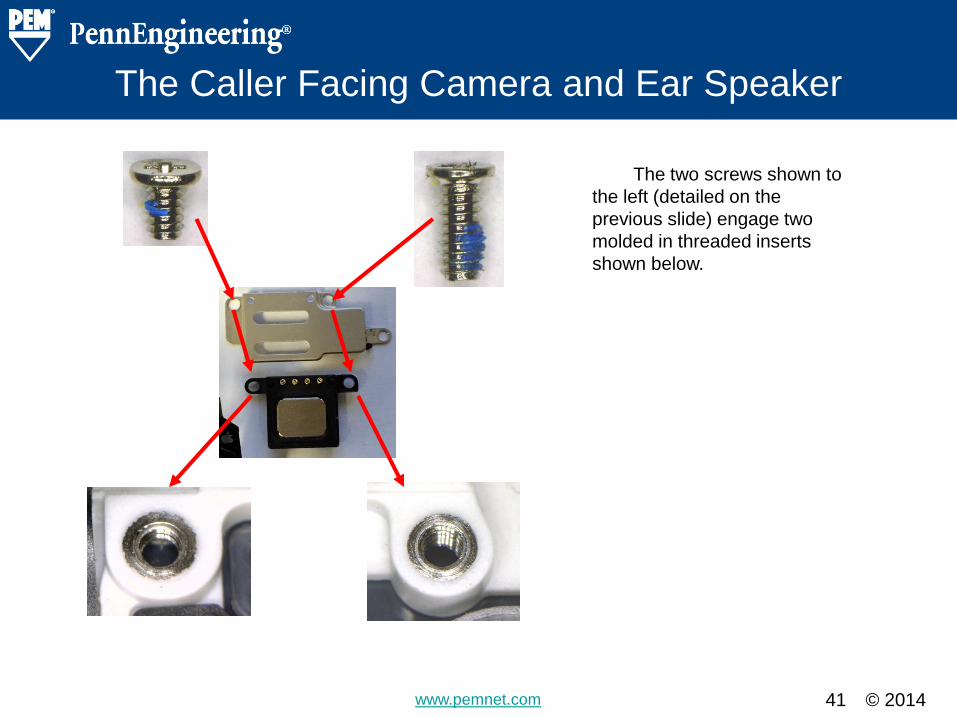
The Caller Facing Camera and Ear Speaker
41
The two screws shown to
the left (detailed on the
previous slide) engage two
molded in threaded inserts
shown below.
© 2014 www.pemnet.com
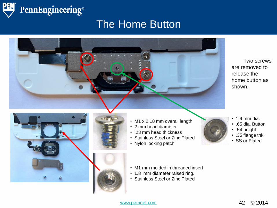
The Home Button
42
• M1 x 2.18 mm overall length
• 2 mm head diameter.
• .23 mm head thickness
• Stainless Steel or Zinc Plated
• Nylon locking patch
• M1 mm molded in threaded insert
• 1.8 mm diameter raised ring.
• Stainless Steel or Zinc Plated
Two screws
are removed to
release the
home button as
shown.
• 1.9 mm dia.
• .65 dia. Button
• .54 height
• .35 flange thk.
• SS or Plated
© 2014 www.pemnet.com
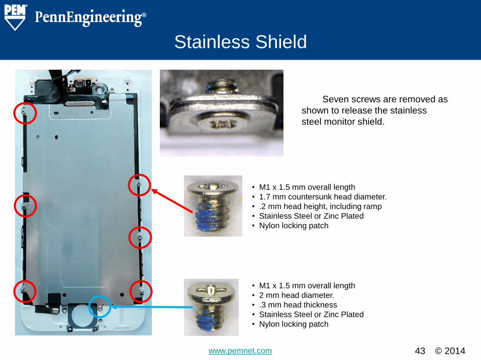
Stainless Shield
43
• M1 x 1.5 mm overall length
• 1.7 mm countersunk head diameter.
• .2 mm head height, including ramp
• Stainless Steel or Zinc Plated
• Nylon locking patch
• M1 x 1.5 mm overall length
• 2 mm head diameter.
• .3 mm head thickness
• Stainless Steel or Zinc Plated
• Nylon locking patch
Seven screws are removed as
shown to release the stainless
steel monitor shield.
© 2014 www.pemnet.com
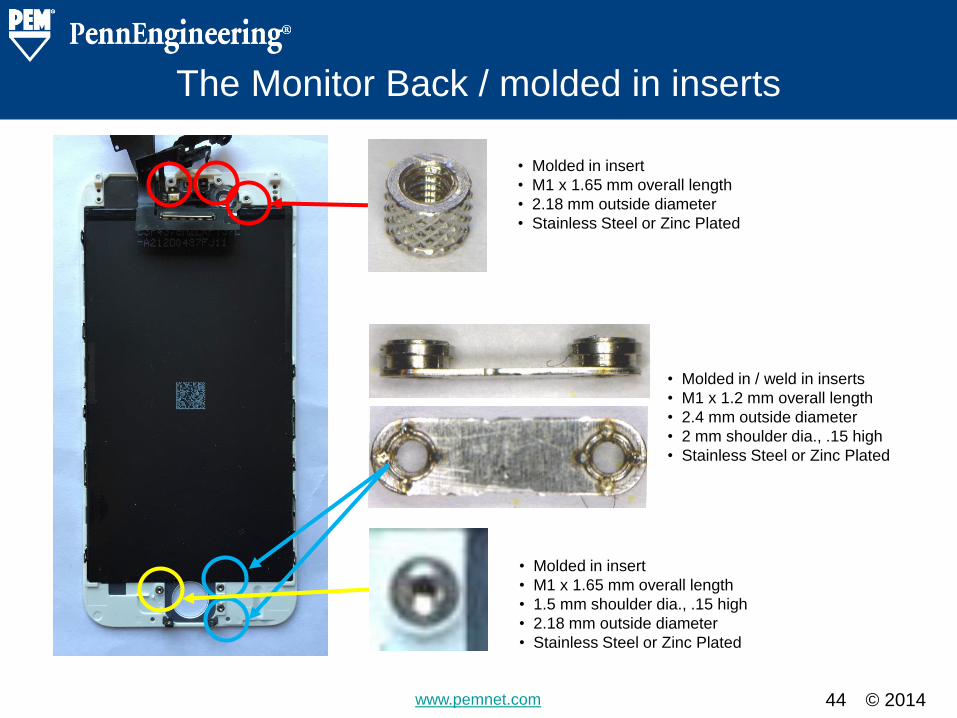
The Monitor Back / molded in inserts
44
• Molded in insert
• M1 x 1.65 mm overall length
• 2.18 mm outside diameter
• Stainless Steel or Zinc Plated
• Molded in / weld in inserts
• M1 x 1.2 mm overall length
• 2.4 mm outside diameter
• 2 mm shoulder dia., .15 high
• Stainless Steel or Zinc Plated
• Molded in insert
• M1 x 1.65 mm overall length
• 1.5 mm shoulder dia., .15 high
• 2.18 mm outside diameter
• Stainless Steel or Zinc Plated
© 2014 www.pemnet.com 45
Fastener Summary
Section Heading Slide – Do Not Remove

© 2014 www.pemnet.com 46
The Screws
Detail Slide – Copy and use for details. Create a table of the fasteners found in the teardown.
Note thread sizes, lengths, drivers, etc. Multiple pages
can be used for different style fasteners
• M1 x 4 mm overall length
• 1.5 mm head diameter
• .4 mm head thickness
• Gold Dye per the phone color
• Nylon locking patch
• Quantity 2
• Slide # 4
• M1.2 x 2.2 mm overall length
• 2 mm head diameter
• .35 mm head thickness
• Stainless Steel or Zinc Plated
• Nylon locking patch
• Quantity 13
• Slide #’s 7,18,19,21,22,31
• M1.2 x 3 mm overall length
• 2 mm head diameter
• .35 mm head thickness
• Stainless Steel or Zinc Plated
• Nylon locking patch
• Quantity 7
• Slide #’s 9,11,13,14,21,22,31,36
• M1 x 1.2 mm overall length
• 2 mm head diameter
• .3 mm head thickness
• Stainless Steel or Zinc Plated
• Nylon locking patch
• Quantity 7
• Slide #’s 9,11,16,17,18,19
• Coupling Screw M1 internal thread in head
• M1.2 external screw thread
• 2.4 mm head diameter, 2.25 mm overall length
• .73 mm head thickness
• 1.6 mm diameter shoulder
• .4 mm shoulder height
• Stainless Steel or Zinc Plated
• Nylon locking patch
• Quantity 1
• Slide #’s 10,11
• M1.2 x 2.6 mm overall length
• 2 mm head diameter
• .35 mm head thickness
• Stainless Steel or Zinc Plated
• Nylon locking patch
• Quantity 1
• Slide #’s 13,14

© 2014 www.pemnet.com 47
The Screws
Detail Slide – Copy and use for details. Create a table of the fasteners found in the teardown.
Note thread sizes, lengths, drivers, etc. Multiple pages
can be used for different style fasteners
• M1 x 1.5 mm overall length
• 2 mm head diameter
• .3 mm head thickness
• Stainless Steel or Zinc Plated
• Nylon locking patch
• Quantity 2
• Slide #’s 16,43
• M1.2 x 1.5 mm overall length
• 2 mm head diameter
• .3 mm head thickness
• Stainless Steel or Zinc Plated
• Nylon locking patch
• Quantity 11
• Slide #’s 18,19,23,24,25,26,32,34
• M1.2 x 2 mm overall length
• 2 mm head diameter
• .35 mm head thickness
• Stainless Steel or Zinc Plated
• Nylon locking patch
• Quantity 2
• Slide #’s 23,24
• M1.2 x 1.72 mm overall length
• 2 mm head diameter
• .35 mm head thickness
• Stainless Steel or Zinc Plated
• Nylon locking patch
• Quantity 3
• Slide #’s 27,30
• M1 x 3 mm overall length
• 2 mm head diameter
• .3 mm head thickness
• Stainless Steel or Zinc Plated
• Nylon locking patch
• Quantity 1
• Slide #’s 40,41
• M1 x 1.72 mm overall length
• .3 mm head thickness
• 2.5 mm head diameter
• 1.75 mm shoulder dia.
• .42 shoulder height
• Stainless Steel or Zinc Plated
• Nylon locking patch
• Quantity 1
• Slide # 29

© 2014 www.pemnet.com 48
The Screws
Detail Slide – Copy and use for details. Create a table of the fasteners found in the teardown.
Note thread sizes, lengths, drivers, etc. Multiple pages
can be used for different style fasteners
• M1 x 2 mm overall length
• 2 mm head diameter
• .3 mm head thickness
• Stainless Steel or Zinc Plated
• Nylon locking patch
• Quantity 4
• Slide #’s 40,41,42
• M1 x 1.5 mm overall length
• 2 mm head diameter
• .3 mm head thickness
• Stainless Steel or Zinc Plated
• Nylon locking patch
• Quantity 1
• Slide #’s 43
• M1 x 1.5 mm overall length
• 1.7 mm countersunk head diameter
• .2 mm head height, including ramp
• Stainless Steel or Zinc Plated
• Nylon locking patch
• Quantity 6
• Slide #’s 43
• M1.2 x 3 mm overall length
• 1.2 mm shoulder diameter
• 1.5 mm shoulder length
• 2 mm head diameter
• .35 mm head thickness
• Quantity 3
• Slide #’s 33,35
© 2014 www.pemnet.com
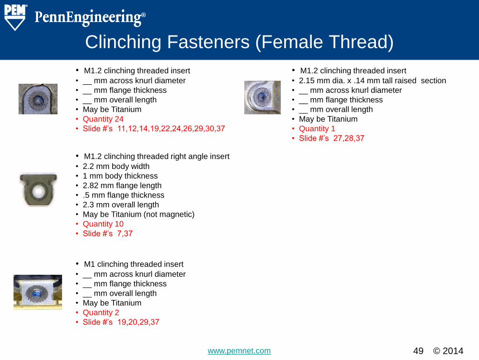
Clinching Fasteners (Female Thread)
49
• M1.2 clinching threaded insert
• __ mm across knurl diameter
• __ mm flange thickness
• __ mm overall length
• May be Titanium
• Quantity 24
• Slide #’s 11,12,14,19,22,24,26,29,30,37
• M1.2 clinching threaded right angle insert
• 2.2 mm body width
• 1 mm body thickness
• 2.82 mm flange length
• .5 mm flange thickness
• 2.3 mm overall length
• May be Titanium (not magnetic)
• Quantity 10
• Slide #’s 7,37
• M1 clinching threaded insert
• __ mm across knurl diameter
• __ mm flange thickness
• __ mm overall length
• May be Titanium
• Quantity 2
• Slide #’s 19,20,29,37
• M1.2 clinching threaded insert
• 2.15 mm dia. x .14 mm tall raised section
• __ mm across knurl diameter
• __ mm flange thickness
• __ mm overall length
• May be Titanium
• Quantity 1
• Slide #’s 27,28,37
© 2014 www.pemnet.com
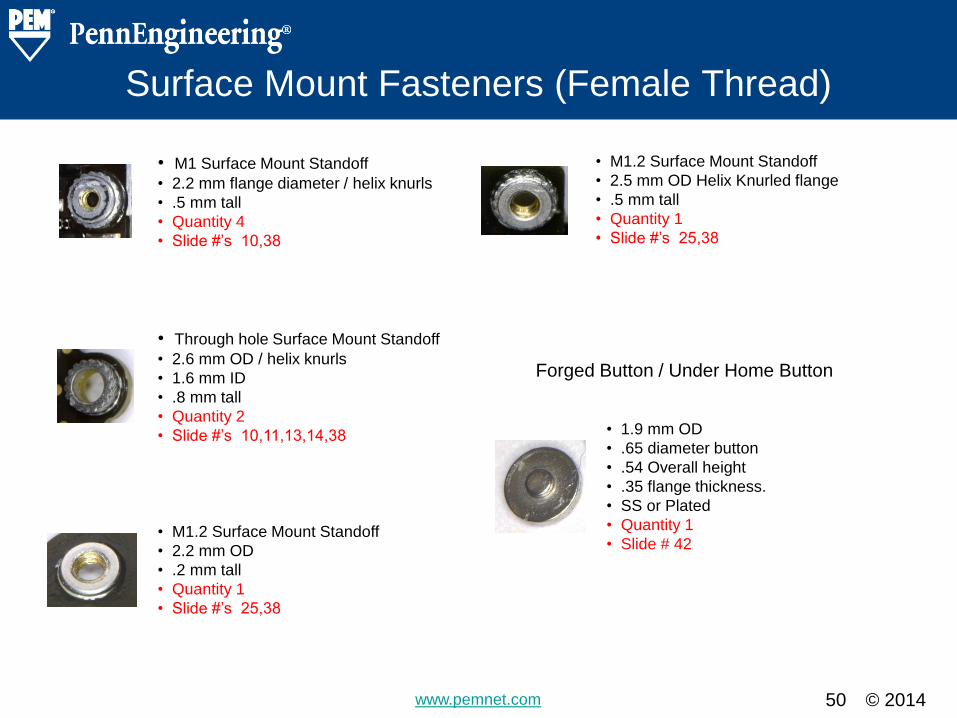
Surface Mount Fasteners (Female Thread)
50
• M1 Surface Mount Standoff
• 2.2 mm flange diameter / helix knurls
• .5 mm tall
• Quantity 4
• Slide #’s 10,38
• Through hole Surface Mount Standoff
• 2.6 mm OD / helix knurls
• 1.6 mm ID
• .8 mm tall
• Quantity 2
• Slide #’s 10,11,13,14,38
• M1.2 Surface Mount Standoff
• 2.2 mm OD
• .2 mm tall
• Quantity 1
• Slide #’s 25,38
• M1.2 Surface Mount Standoff
• 2.5 mm OD Helix Knurled flange
• .5 mm tall
• Quantity 1
• Slide #’s 25,38
Forged Button / Under Home Button
• 1.9 mm OD
• .65 diameter button
• .54 Overall height
• .35 flange thickness.
• SS or Plated
• Quantity 1
• Slide # 42
© 2014 www.pemnet.com
Molded in Fasteners (Female Thread)
51
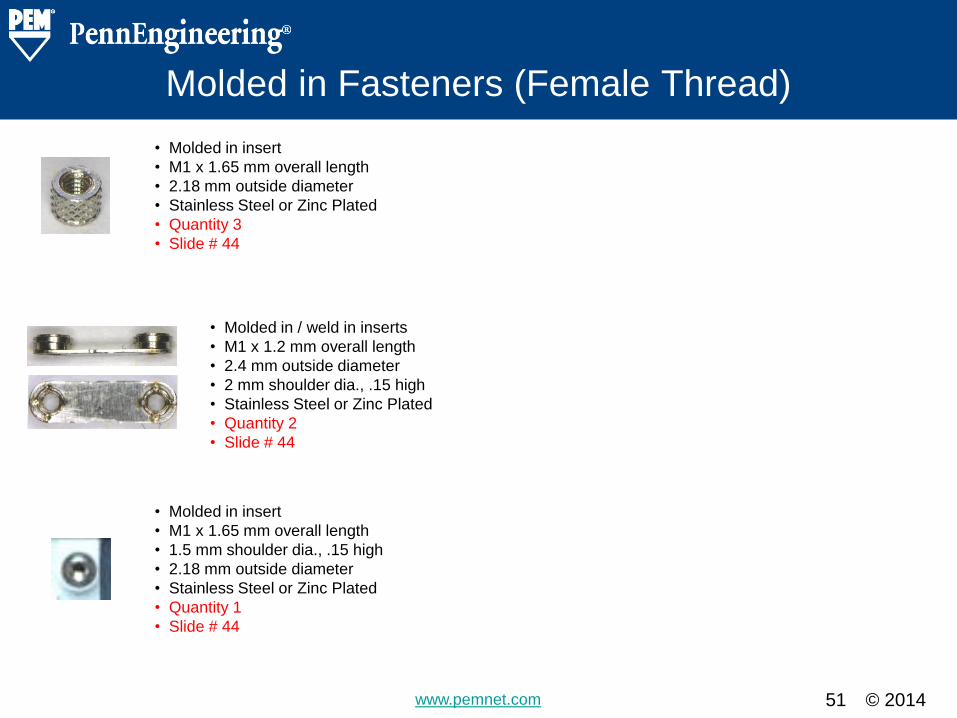
• Molded in insert
• M1 x 1.65 mm overall length
• 2.18 mm outside diameter
• Stainless Steel or Zinc Plated
• Quantity 3
• Slide # 44
• Molded in / weld in inserts
• M1 x 1.2 mm overall length
• 2.4 mm outside diameter
• 2 mm shoulder dia., .15 high
• Stainless Steel or Zinc Plated
• Quantity 2
• Slide # 44
• Molded in insert
• M1 x 1.65 mm overall length
• 1.5 mm shoulder dia., .15 high
• 2.18 mm outside diameter
• Stainless Steel or Zinc Plated
• Quantity 1
• Slide # 44

© 2014 www.pemnet.com 52
Alternate Solutions
PennEngineering® recommendations
of alternate hardware and cost savings
opportunities.
Section Heading Slide – Do Not Remove

© 2014 www.pemnet.com 53
Alternate Solutions
Detail Slide – Copy and use for details. Note any new solutions (PEM or non-PEM).
Highlight the advantages and disadvantages
of each.
PennEngineering® is fully capable of making all of the fasteners shown on slides 46 to 51. Our
experience with forging and materials as well as expertise with self clinching fastener design enable us
to provide a superior solution for the fasteners shown on slide #49 (self clinching inserts). These self
clinching inserts may be more effectively manufactured on forging equipment, and consequently result
in a cost savings and throughput improvement.
In addition to direct replacement and perhaps some manufacturing and material substitution for
functional and cost improvement, some alternate fastening suggestions are presented for specific
situations on the following slides.
© 2014 www.pemnet.com
Monitor Edge Snaps
54
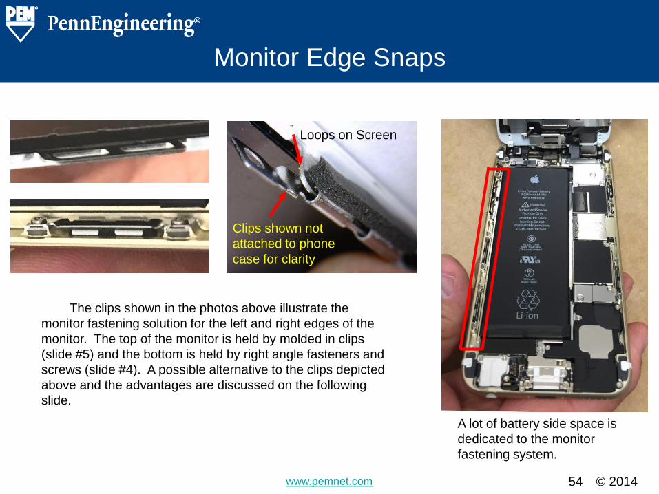
Loops on Screen
Clips shown not
attached to phone
case for clarity
The clips shown in the photos above illustrate the
monitor fastening solution for the left and right edges of the
monitor. The top of the monitor is held by molded in clips
(slide #5) and the bottom is held by right angle fasteners and
screws (slide #4). A possible alternative to the clips depicted
above and the advantages are discussed on the following
slide.
A lot of battery side space is
dedicated to the monitor
fastening system.
© 2014 www.pemnet.com
Monitor Edge Snaps
55
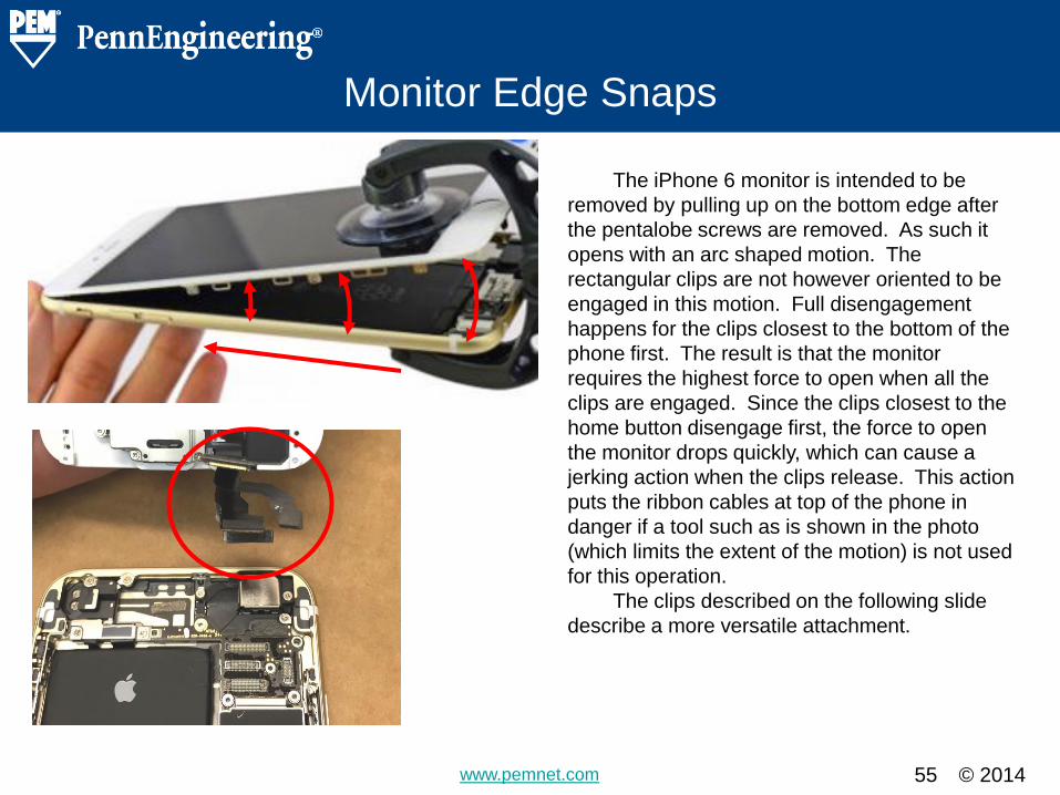
The iPhone 6 monitor is intended to be
removed by pulling up on the bottom edge after
the pentalobe screws are removed. As such it
opens with an arc shaped motion. The
rectangular clips are not however oriented to be
engaged in this motion. Full disengagement
happens for the clips closest to the bottom of the
phone first. The result is that the monitor
requires the highest force to open when all the
clips are engaged. Since the clips closest to the
home button disengage first, the force to open
the monitor drops quickly, which can cause a
jerking action when the clips release. This action
puts the ribbon cables at top of the phone in
danger if a tool such as is shown in the photo
(which limits the extent of the motion) is not used
for this operation.
The clips described on the following slide
describe a more versatile attachment.
© 2014 www.pemnet.com
Monitor Edge Snaps
56
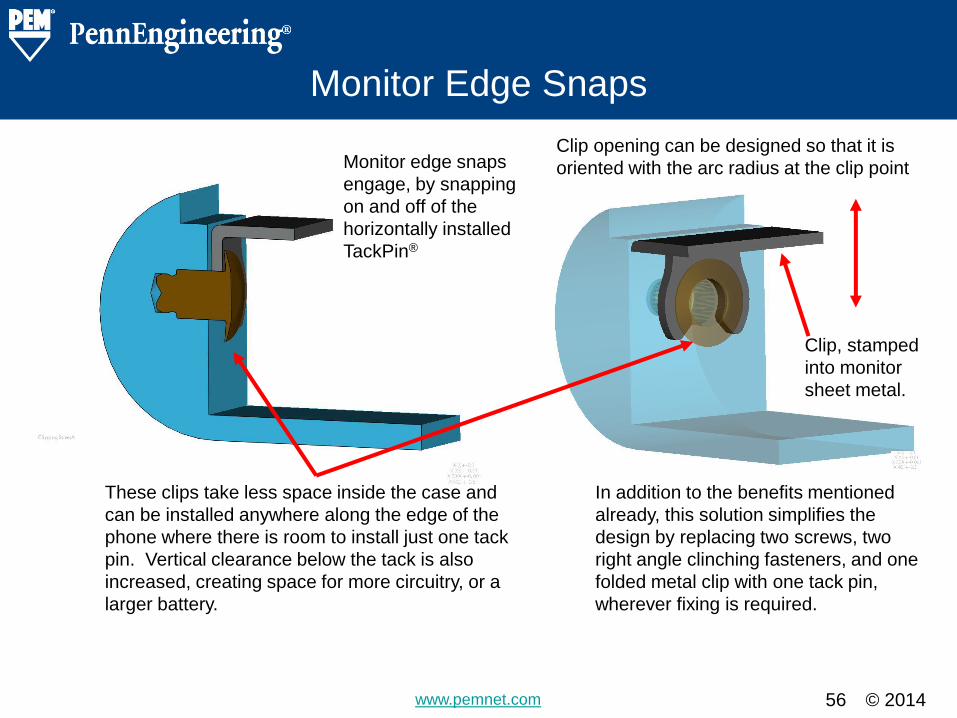
Monitor edge snaps
engage, by snapping
on and off of the
horizontally installed
TackPin®
These clips take less space inside the case and
can be installed anywhere along the edge of the
phone where there is room to install just one tack
pin. Vertical clearance below the tack is also
increased, creating space for more circuitry, or a
larger battery.
In addition to the benefits mentioned
already, this solution simplifies the
design by replacing two screws, two
right angle clinching fasteners, and one
folded metal clip with one tack pin,
wherever fixing is required.
Clip, stamped
into monitor
sheet metal.
Clip opening can be designed so that it is
oriented with the arc radius at the clip point
© 2014 www.pemnet.com
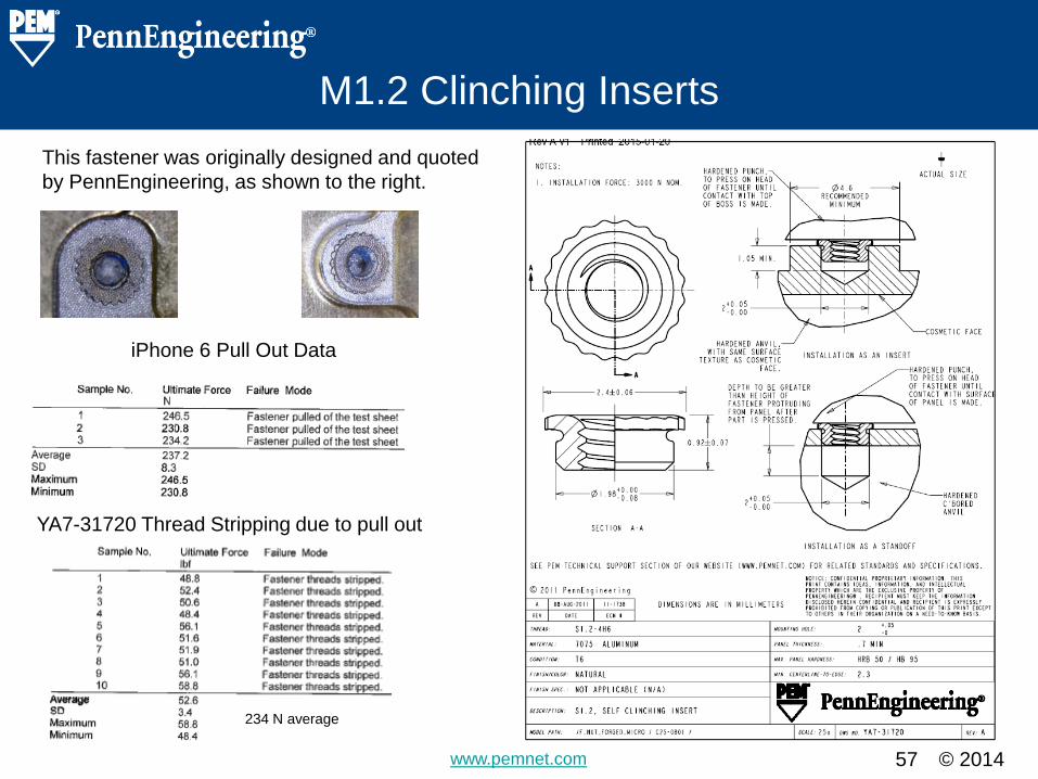
M1.2 Clinching Inserts
57
iPhone 6 Pull Out Data
YA7-31720 Thread Stripping due to pull out
This fastener was originally designed and quoted
by PennEngineering, as shown to the right.
234 N average
© 2014 www.pemnet.com
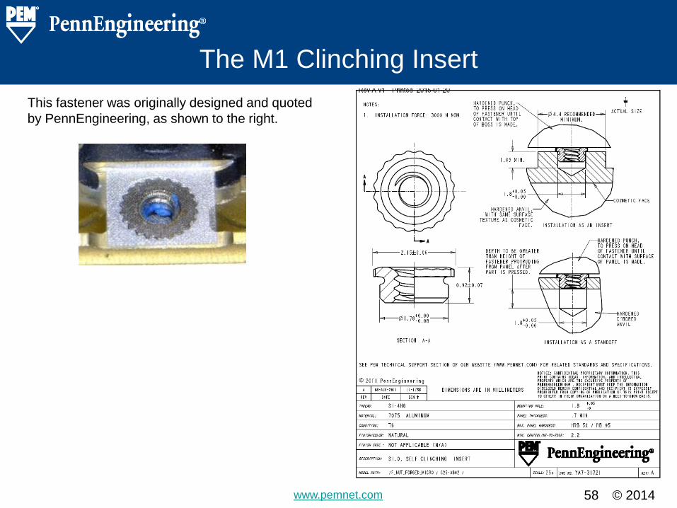
The M1 Clinching Insert
58
This fastener was originally designed and quoted
by PennEngineering, as shown to the right.
© 2014 www.pemnet.com
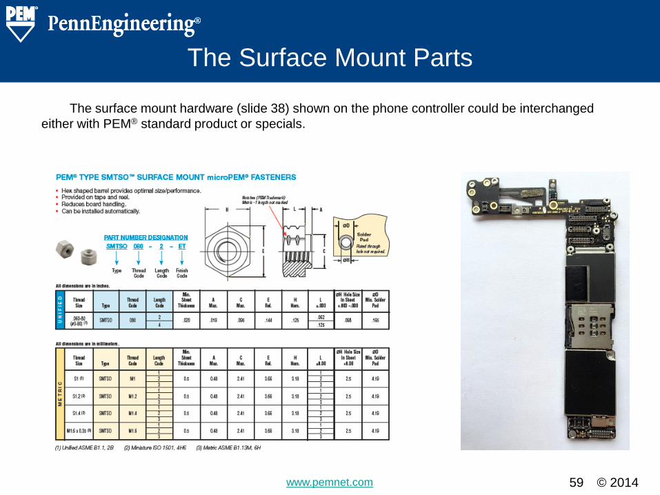
The Surface Mount Parts
59
The surface mount hardware (slide 38) shown on the phone controller could be interchanged
either with PEM® standard product or specials.
© 2014 www.pemnet.com
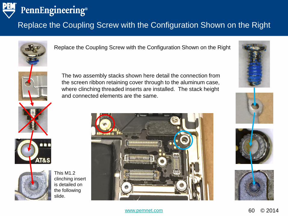
Replace the Coupling Screw with the Configuration Shown on the Right
60
The two assembly stacks shown here detail the connection from
the screen ribbon retaining cover through to the aluminum case,
where clinching threaded inserts are installed. The stack height
and connected elements are the same.
This M1.2
clinching insert
is detailed on
the following
slide.
Replace the Coupling Screw with the Configuration Shown on the Right

© 2014 www.pemnet.com
Soldering to Glass
61
Future designs may benefit from our
capability to solder fasteners directly to the glass
of the monitor.
© 2014 www.pemnet.com
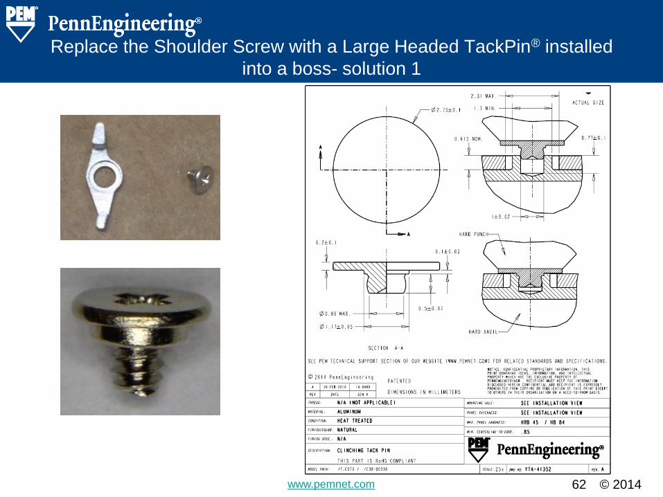
Replace the Shoulder Screw with a Large Headed TackPin® installed
into a boss- solution 1
62
© 2014 www.pemnet.com 63
Fig.3
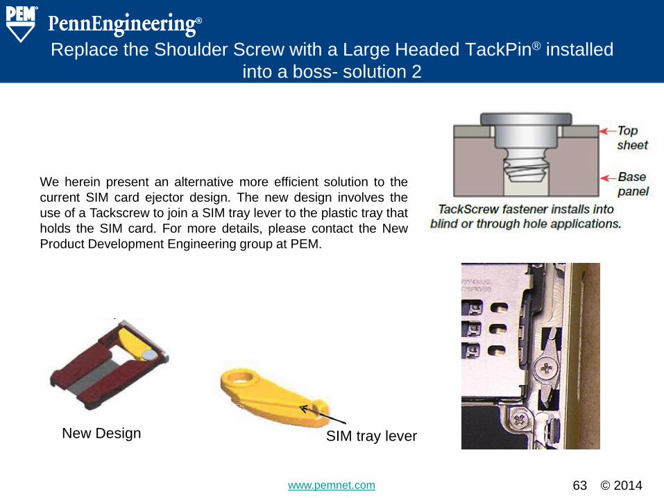
We herein present an alternative more efficient solution to the
current SIM card ejector design. The new design involves the
use of a Tackscrew to join a SIM tray lever to the plastic tray that
holds the SIM card. For more details, please contact the New
Product Development Engineering group at PEM.
SIM tray lever
SIM tray
lever SIM tray lever
New Design
Replace the Shoulder Screw with a Large Headed TackPin® installed
into a boss- solution 2

© 2014 www.pemnet.com 64
Conclusions and Summary
Section Heading Slide – Do Not Remove
© 2014 www.pemnet.com 65
Conclusion
Detail Slide – Copy and use for details. Summarize the findings and alternate
solutions.
The iPhone 6 is as expected a beautiful phone. As is typical with Apple’s phones many threaded
fasteners are used in it’s construction. PennEngineering® may be able to help with fastener
standardization, assembly simplification, cost reduction, and overall product improvement, with the
implementation of some of the alternative fastening solutions suggested.
As was stated earlier, PennEngineering® can produce any of the fastening solutions used in the
phone, within our current manufacturing facilities. Our design and manufacturing expertise may create
cost savings opportunities alone.
Beyond direct replacement there are other improvement possibilities. The hardness of the phone
case was measured to be HRB 40. This is relatively soft, making an insert made from 2024-T4
capable of being clinched. As the data presented in this report shows, the pull out force for the actual
inserts used is significantly lower than the stripping strength of an insert made from 2024-T4 aluminum.
Advantages of 2024-T4 aluminum over the titanium that is currently being used are:
• No electrical potential between the fastener and the case
• No masking of the fastener would be required during the anodization process as is
required with the Titanium
• 2024 aluminum is heat treated after forming to give it a high hardness and strength. Because
it is more workable in it’s soft state than Titanium, tools last longer and production rate is
increased. Both factors lend themselves to lower cost to manufacture than Titanium.
The side clips for the monitor might be replaced with a TackPin® and snap solution as is described
in slides 54-56.
© 2014 www.pemnet.com
Conclusion
66
The coupling screw described in slides 11 and 60, might be eliminated with the use of another
surface mount standoff as is shown on slide 11.
The use of surface mount technology that is used on the circuit board may also lend itself to future
innovation by soldering PEM® fasteners directly to the monitor glass.
Finally the use of one large headed tack pin installed into a boss in the case could replace a
custom shoulder screw and a threaded insert .