Peltier Application Notes
47
page 1 of 8 date 01/2009 PART NUMBER: CP Series DESCRIPTION: application notes APPLICATION NOTES 1. PELTIER HISTORY Early 19th century scientists, Thomas Seebeck and Jean Peltier, first discovered the phenomena that are the basis for today’s thermoelectric industry. Seebeck found that if you placed a temperature gradient across the junctions of two dissimilar conductors, electrical current would flow. Peltier, on the other hand, learned that passing current through two dissimilar electrical conductors, caused heat to be either emitted or absorbed at the junction of the materials. It was only after mid-20th Century advancements in semiconductor technology, however, that practical applications for thermoelectric devices became feasible. With modern techniques, we can now produce thermoelectric “modules” that deliver efficient solid state heat-pumping for both cooling and heating; many of these units can also be used to generate DC power at reduced efficiency. New and often elegant uses for thermoelectrics continue to be developed each day. Ceramic 2. PELTIER STRUCTURE Substrate
-
Upload
khawar-mehdi -
Category
Documents
-
view
30 -
download
0
description
basic concept of peltier effect
Transcript of Peltier Application Notes
page 1 of 8
date 01/2009
PART NUMBER: CP Series DESCRIPTION: application notes
APPLICATION NOTES1. PELTIER HISTORY
Early 19th century scientists, Thomas Seebeck and Jean Peltier, first discovered the phenomena that are the basis for today’s thermoelectric industry.
Seebeck found that if you placed a temperature gradient across the junctions of two dissimilar conductors, electrical current would flow. Peltier, on the
other hand, learned that passing current through two dissimilar electrical conductors, caused heat to be either emitted or absorbed at the junction of
the materials. It was only after mid-20th Century advancements in semiconductor technology, however, that practical applications for thermoelectric
devices became feasible. With modern techniques, we can now produce thermoelectric “modules” that deliver efficient solid state heat-pumping for
both cooling and heating; many of these units can also be used to generate DC power at reduced efficiency. New and often elegant uses for
thermoelectrics continue to be developed each day.
Ceramic
2. PELTIER STRUCTURE
Substrate
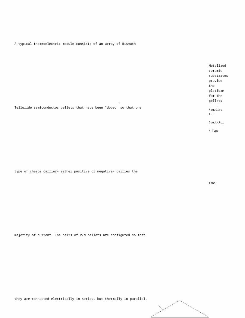
A typical thermoelectric module consists of an array of Bismuth
Telluride semiconductor pellets that have been “doped” so that one
type of charge carrier– either positive or negative– carries the
majority of current. The pairs of P/N pellets are configured so that
they are connected electrically in series, but thermally in parallel.
Metalized ceramic substrates provide the platform for the pellets
Negative (-)
Conductor
N-TypeTabsand the small conductive tabs that connect them. Semiconductor
Pellets
Positive (+)
P-TypeSemiconductor
Pellets
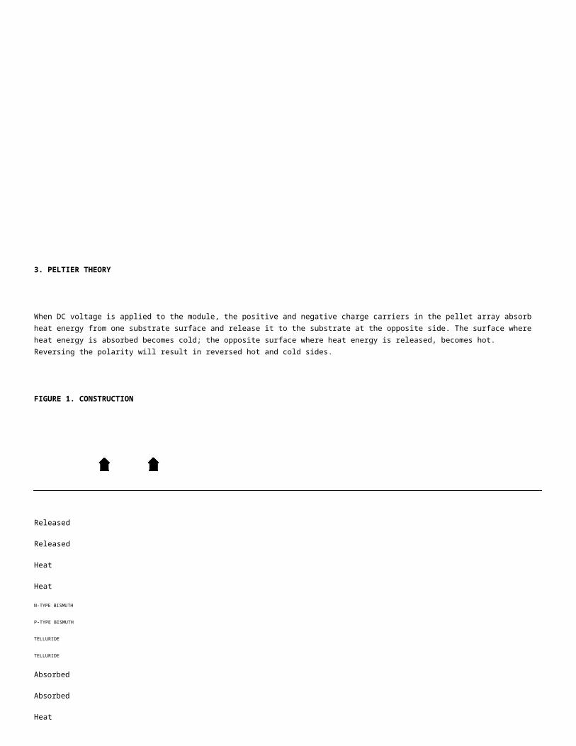
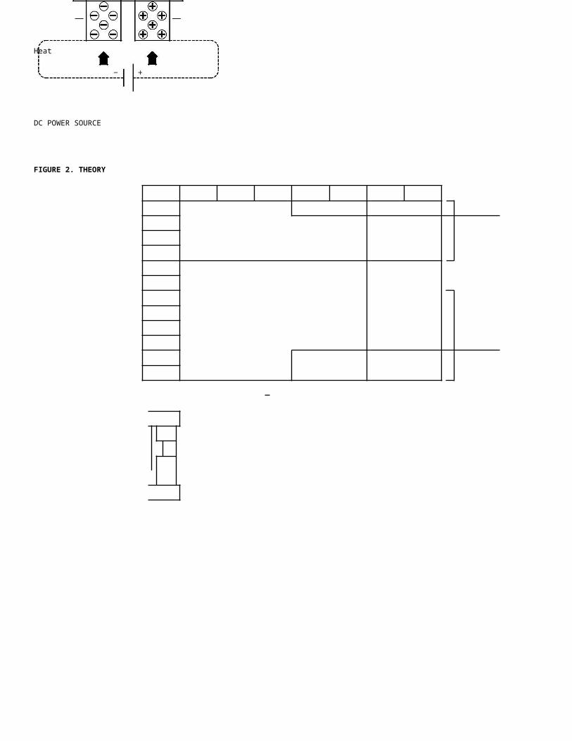
3. PELTIER THEORY
When DC voltage is applied to the module, the positive and negative charge
carriers in the pellet array absorb heat energy from one substrate surface
and release it to the substrate at the opposite side. The surface where heat
energy is absorbed becomes cold; the opposite surface where heat energy is
released, becomes hot. Reversing the polarity will result in reversed hot and
cold sides.
FIGURE 1. CONSTRUCTION
Released ReleasedHeat Heat
N-TYPE BISMUTH P-TYPE BISMUTH
TELLURIDE TELLURIDE
Absorbed AbsorbedHeat Heat
DC POWER SOURCEFIGURE 2. THEORY
20050 SW 112th
Ave. Tualatin, Oregon 97062 phone 503.612.2300 fax 503.612.2382

page 2 of 8
date 01/2009
PART NUMBER: CP Series DESCRIPTION: application notes
4. HOW TO READ THE TECHNICAL DATA
4a. REGARDING PELTIER MODULE SPECIFICATIONS
The maximum electric current (Imax) and the maximum voltage (Vmax) values are not the absolute maximum rated values. Instead, considering
performance coefficients and heat radiation design, it is recommended that products are used to around 70% of the maxi-mum electric current and
voltage values. If products are used with voltages and currents which exceed the maximum values, heat absorption will decrease and Joule heating
will increase. As a result, not only will efficiency be reduced, but the increase in temperature will have an adverse effect on the soldering connecting
the semiconductor and could lead to a break down and reverse diffusion.
4b. REGARDING PELTIER MODULE FUNCTION DIAGRAMS
The maximum temperature difference ( Tmax) is the temperature difference between the sides of the semiconductor when the heat absorption is
0(W). Also, the maximum heat absorption, Qmax, is attained when the temperature difference between the sides of the semiconductor is 0. Even
though these are both not actual values but theoretical figures, please use these as a guide for choosing modules.
For the relationship between electric current, voltage, temperature difference and heat absorption, please consult the function diagrams in the
design examples.
20050 SW 112th
Ave. Tualatin, Oregon 97062 phone 503.612.2300 fax 503.612.2382
page 3 of 8
date 01/2009
PART NUMBER: CP Series DESCRIPTION: application notes
5. DESIGN EXAMPLES
5a. EXAMPLE 1
(ex. CP60440)
What is the heat absorption (Qc) and supplied current (I) when Th=50°C, Tc=10°C, Voltage=12 V dc? 1) Find T
T = Th-Tc
= 50-10=40°C
2) Find the supplied voltage from the function diagram From
the diagram, at Th=50°C I=3.77 A
3) Find the heat absorption (Qc) from the function diagram
The current found in [2] is 3.77 A, so from the diagram at Th=50°C Qc=20.75 W
FIGURE 3. FUNCTION DIAGRAM
1) Potential difference across the Peltier Module (V).
2) The connection between T (°C) for each supplied current and voltage (V).
3) The connection between T (°C) for each supplied current and heat absorption (W).
4) Heat absorption of the Peltier Module (W).
5) The temperature difference ( T) shows the difference between the hot side and cool side of the peltier module and the electrodes. It is not the
difference between the cool side and the background temperature.
20050 SW 112th
Ave. Tualatin, Oregon 97062 phone 503.612.2300 fax 503.612.2382
page 4 of 8
date 01/2009
PART NUMBER: CP Series DESCRIPTION: application notes
5b. EXAMPLE 2
How to choose a cooler unit When choosing a cooler unit that suits the functions you require, you need to know the heat absorption rate and temperature difference. These two things can be calculated easily.
Example of heat calculation Conditions: Internal dimensions of box 500 x 200 x 100 (mm) 10 literswhen cooling in an enclosed External dimensions 560 x 260 x 160 (mm)environment Thermal insulation 30 (mm) urethane foam
Internal temperature 5°CAmbient temperature 30°C
1) Thermal conductivity λ
λ = 0.025 (W/m°C): Thermal conductivity of urethane foamt = 0.03 (m): Thickness of thermal insulation
2) Surface area of box (at center of thermal insulation) S
S = (0.53 x 0.23) x 2 = (0.23 x 0.13) x 2+(0.53 x 0.13) x 2 = 0.44 (m2)
3) Overall heat transfer rate K
Thermal conductivity of external surface: h1 = 20 (W/m2°C)Thermal conductivity of internal surface: h2 = 10 (W/m2°C)K = 1/{(1/h1) + (1/h2) + t/λ}|
= 1/{(1/20) + (1/10) + 0.03/0.025}| = 0.74 (W/m2°C)
4) Amount of heat entering the insulated box from external sources Q1 Q1 = S ⋅ K ⋅ T
= 0.44 x 0.74 x (30-5)
5) Necessary heat absorption Q
Internal thermal loading (in the case of loading from an internal heat source): Let Q2 = 5 (W) Q = Q1 + Q2 = 13.1 (W)
6) Choice of cooler unit
Adding a safety margin of 25% to the necessary heat absorption give 16.4 (W). In other words, a cooler unit that provides heat absorption of over 16 (W) and a temperature difference of at least 25° is necessary.
Ex. CP30238 can easily give a 30° difference at 6 W of heat absorption, so 16.4 W / 6 W means
roughly three units are necessary.
20050 SW 112th
Ave. Tualatin, Oregon 97062 phone 503.612.2300 fax 503.612.2382

page 5 of 8
date 01/2009
PART NUMBER: CP Series DESCRIPTION: application notes
5c. EXAMPLE 3
Example of heat calculation Conditions: Internal dimensions of box 250 x 200 x 100 (mm) 5 literswhen cooling in an enclosed External dimensions 310 x 260 x 160 (mm)environment Thermal insulation 30 (mm) urethane foam
Cooling time 1 hourInitial water temperature 20°CCooled temperature 10°CAmbient temperature 30°C
1) Thermal conductivity λλ = 0.025 (W/m°C): Thermal conductivity of urethane foamt = 0.03 (m): Thickness of thermal insulation
2) Surface area of box (at center of thermal insulation) SS = (0.28 x 0.23) x 2 = (0.23 x 0.13) x 2+(0.28 x 0.13) x 2 = 0.26 (m2)
3) Overall heat transfer rate K
Thermal conductivity of external surface: h1 = 20 (W/m2°C)Thermal conductivity of internal surface: h2 = 200 (W/m2°C)K = 1/{(1/h1) + (1/h2) + t/λ}|
= 1/{(1/20) + (1/200) + 0.03/0.025}| = 0.8 (W/m2°C)
4) Amount of heat entering the insulated box from external sources Q1 Q1 = S ⋅ K ⋅ T
= 0.26 x 0.8 x (30-10)
5) Necessary heat absorption to cool water Q2
Cp: specific heat capacity of water (Kcal / Kg⋅°C)p: specific density of water (Kg / L) v: volume of water (L)
Q2 = Cp ⋅ p ⋅ v ⋅ T In other words, to cool the water in one hour.= 1 x 1 x 5 x (20-10) Q2 = 50,000 cal x 4.19 J ÷ 3600 sec = 58.2 (W)
= 50 Kcal (1 cal = 4.19 J 1 J / s = 1 W)
6) Necessary heat absorption Q
There is no thermal loading from the water. Therefore, Q3 = 0 Q = Q1 + Q2 + Q3
= 4.2 + 58.2 + 0 = 62.4 (W)
7) Choice of cooler unit
Adding a safety margin of 25% to the necessary heat absorption give 78.0 (W). In other words, a cooler unit that provides heat absorption of over 78 (W) and a temperature difference of at least 20° is necessary.
Ex. CP60333 can easily give a 25° difference at 16 W of heat absorption, so 78.0 W / 16 Wmeans roughly five units are necessary.However, since the heat absorption calculations include the heat capacity of water, inactuality a smaller number of units would perform the task (because the heat absorption isgreater under powered conditions).
20050 SW 112th
Ave. Tualatin, Oregon 97062 phone 503.612.2300 fax 503.612.2382
page 6 of 8
date 01/2009
PART NUMBER: CP Series DESCRIPTION: application notes
6. MOUNTING METHOD
Using peltier modules When a direct current is passed through a Peltier Module, the low temperature the low temperature side absorbs heat and the high temperature side emits heat, so that a temperature difference exists across the surfaces. However, since the heat emitted is more reactive to the amount of electricity input into the module than the heat absorbed, if a direct current is continuously passed through the module the emitted heat will exceed the absorbed heat and both sides of the unit will become hot.For that reason, it is necessary to connect the module to a radiator such as aluminum fins to efficiently disperse the emitted heat.A Peltier Module fitted between a radiator and a heat extractor like an aluminum block for use as a cool-ing device is called a Cooler Unit
Assembling a cooler unit 1) Wipe the surface of the radiator fins to be attached to the Peltier Module free of dirt and grease using alcohol or similar and thinly spread thermally-conductive silicon grease on the appropriate area.
2) In the same way, wipe the heat emitting side of the Peltier Module with alcohol or similar and thinly spread with thermally-conductive silicon grease. At this point, take care that nothing is attached to the unit.
3) Place the heat-emitting side of the Peltier Module onto the appropriate place on the radiator fins. While applying light pressure to the unit, slide the unit back and forth, left and right, approximately 20 times to ensure a good fit and to lose any layer of air between the connecting sides. (figure 4)
4) Wipe the heat absorbing side of the Peltier Module free of dirt and grease with alcohol or similar and thinly apply thermally-conductive silicon grease.
FIGURE 4. INSTALLING THE
5) In the same way, wipe the surface of the aluminum PELTIER MODULE block to be attached to the Peltier Module with alcohol
or similar and thinly apply thermally-conductive silicon grease.
6) Place the aluminum block onto the heat absorbing side of the Peltier Module. Once again, apply light pressure to the block and slide it back and forth, left and right, to ensure a tight fit and lose any layer of air between the connecting sides. (figure 5)
7) Check that the holes in the aluminum block are in line with the screw holes in the radiator fins. Put one of each type of washer (in the order: spring washer, flat washer, silicon washer) onto the fixing screws (SUS), apply liquid thread lock and then put the screws into the holes.
8) Tighten the screws until the washers are gently held in place. While doing this, to ensure that even force is applied across the module, apply 200 ~ 300 N(for a 40 mm square unit) of pressure to the center of the aluminum block and tighten each of the screws alternatively little by little. (figure 6)
FIGURE 5. INSTALLING THE ALUMINUM BLOCK
9) When the module is gently secured, tighten the screws alternately in the same manner as in step 8 to a torque of 10 N⋅m. Continue tightening to a final torque of20 ~ 30 N⋅m (M3-M4). When tightening the screws, take care to avoid unbalanced stress to the unit.
FIGURE 5. ORDER OF SCREW
TIGHTENING
20050 SW 112th
Ave. Tualatin, Oregon 97062 phone 503.612.2300 fax 503.612.2382

page 7 of 8
date 01/2009
PART NUMBER: CP Series DESCRIPTION: application notes
6. MOUNTING METHOD CONTINUED
Assembling a cooler unit 10) When the screws are tightened to the above torque, let the unit stand for 30 ~ 60 minutes and then continued once again check the screw tightening torque. Also, wipe away any excess silicon grease. When
M4 is tightened to 10 N⋅m, approximately 100 N of axial tension is being applied. For a single 40 mm square module, tightening to 200 ~ 300 N of axial tension is a sufficient load.
11) As a protection against humidity, seal the perimeter of the Peltier Module with a silicon sealant or similar and allow to dry for the requisite time. (figure 7)
12) When the above process is complete, measure the resistance value of the unit to check for abnormalities. The resistance value cannot be measured with a normal tester. An A/C 4 probe resistance gauge must be used. (ex. Tsuruga Electric model no. 3566)
FIGURE 7. HUMIDITY PROTECTION
FOR THE PELTIER
MODULE PERIMETER
7. MOUNTING GUIDELINES
While building peltier modules into your cooling unit, please be cautious with regard to the following:
1) Ensure that the peltier module has full surface contact with the heat exchanger. Ideally, deviation from flatness should be kept under 0.02 mm.
2) Thinly spread thermally conductive grease between the peltier module surface and the heat exchanger.
3) Be sure to apply proper materials for protecting the peltier module from moisture, such as silicone and epoxy.
4) Optimum efficiency is not obtained at maximum voltage or maximum electric current. It is recommended that the voltage and current are set
to about 70% of their maximum.
5) Changing the current polarity rapidly as a method of modulation will shorten the life of the unit. Please avoid this method of use.
8. GENERAL CAUTIONS
Precautions for use:
1) Do not allow the Th-side of the peltier module exceed 80°C or 90°C on other modules.
2) Dropping or exerting mechanical shock on the unit can cause it to break. Please take care in the handling of the product.
3) Please make sure not to store the peltier module in high humidity direct exposure to sunlight. Also avoid exposure to dew or condensation.
The appropriate temperature and humidity for storage is 5~35°C and 20~75% RH.
20050 SW 112th
Ave. Tualatin, Oregon 97062 phone 503.612.2300 fax 503.612.2382

page 8 of 8
date 01/2009
PART NUMBER: CP Series DESCRIPTION: application notes
9. HEAT TRANSFER FORMULAE
1) Heat gained or lost through walls Q =
(A x T x K) / ( X)
Where:
Q = Heat (Watts)
A = External surface area of container (m2)
T = Temperature difference (inside vs. outside of container) (Kelvin)
K = Thermal conductivity of insulation (Watt / meter Kelvin)
X = Insulation thickness (m)
2) Time required to change the temperature of an object
t = (m x Cp x T) / Q
Where:
t = Time interval (seconds) m
= Weight of the object (kg)
Cp = Specific heat of material (J / (kg K))
T = Temperature change of object (Kelvin)
Q = Heat added or removed (Watts)
Note: It should be remembered that thermoelectric devices do not add or remove heat at a constant rate when T is changing. An
approximation for average Q is: Qave = (Q ( T max) + Q ( T min)) / 2
3) Heat transferred to or from a surface by convection Q = h
x A x T
Where:
Q = Heat (Watts)
h = Heat transfer coefficient (W / (m2 K)), 1 ~ 30 = “Free” convection - gasses, 10 ~ 100 = “Forced” convection - gasses
A = Exposed surface area (m2)
T = Surface temperature - Ambient (Kelvin)
Thermal Conductivity of Some Common Materials (W/m-K)
Material 27 °C 50 °CPure Copper 401 399Pure Aluminum 237 238Aluminum Alloy 2024-T6 177 179Aluminum Alloy 195 168 169Brass 110 116Bronze 54 57Pure Nickel 91 87Solder (Tin/Lead) 47 44Lead-Free Solder (80%Au, 20%Sn) 57 55Air 0.0263 0.0285Water 0.613 0.645
20050 SW 112th
Ave. Tualatin, Oregon 97062 phone 503.612.2300 fax 503.612.2382