Peer-to-peer service provisioning in cloud computing ... · Peer-to-peer service provisioning in...
31
J Supercomput (2013) 65:154–184 DOI 10.1007/s11227-011-0710-5 Peer-to-peer service provisioning in cloud computing environments Rajiv Ranjan · Liang Zhao Published online: 21 October 2011 © Springer Science+Business Media, LLC 2011 Abstract This paper aims to advance the management and delivery of services in large, heterogeneous, uncertain, and evolving cloud computing environments. The goal is important because such systems are becoming increasingly popular, yet ex- isting service management methods do not scale well, and nor do they perform well under highly unpredictable conditions. If these problems can be solved, then Infor- mation Technology (IT) services can be made to operate in more scalable and reliable manner. In this paper, we present a peer-to-peer approach for managing services in large scale, dynamic, and evolving cloud computing environments. The system compo- nents such as virtualized services, computing servers, storage, and databases self- organize themselves using a peer-to-peer networking overlay. Inter-networking sys- tem components through peer-to-peer routing and information dissemination struc- ture is essential to avoid the problems of management bottleneck and single point of failure that is predominantly associated with traditional centralized and hierarchical distributed (grids/clouds) system design approaches. We have validated our approach by conducting a set of rigorous performance evaluation study using the Amazon EC2 cloud computing environment. The results prove that managing services based on peer-to-peer routing and information dissemination structure is feasible and offers R. Ranjan ( ) · L. Zhao Service Oriented Computing (SOC) Research Group, School of Computer Science and Engineering, The University of New South Wales, Sydney, Australia e-mail: [email protected] L. Zhao e-mail: [email protected] R. Ranjan Information Engineering Laboratory, CSIRO Information and Communication Technologies (ICT) Centre, North Road, Acton, ACT 2601, Australia e-mail: [email protected]
Transcript of Peer-to-peer service provisioning in cloud computing ... · Peer-to-peer service provisioning in...
J Supercomput (2013) 65:154–184DOI 10.1007/s11227-011-0710-5
Peer-to-peer service provisioning in cloud computingenvironments
Rajiv Ranjan · Liang Zhao
Published online: 21 October 2011© Springer Science+Business Media, LLC 2011
Abstract This paper aims to advance the management and delivery of services inlarge, heterogeneous, uncertain, and evolving cloud computing environments. Thegoal is important because such systems are becoming increasingly popular, yet ex-isting service management methods do not scale well, and nor do they perform wellunder highly unpredictable conditions. If these problems can be solved, then Infor-mation Technology (IT) services can be made to operate in more scalable and reliablemanner.
In this paper, we present a peer-to-peer approach for managing services in largescale, dynamic, and evolving cloud computing environments. The system compo-nents such as virtualized services, computing servers, storage, and databases self-organize themselves using a peer-to-peer networking overlay. Inter-networking sys-tem components through peer-to-peer routing and information dissemination struc-ture is essential to avoid the problems of management bottleneck and single point offailure that is predominantly associated with traditional centralized and hierarchicaldistributed (grids/clouds) system design approaches. We have validated our approachby conducting a set of rigorous performance evaluation study using the Amazon EC2cloud computing environment. The results prove that managing services based onpeer-to-peer routing and information dissemination structure is feasible and offers
R. Ranjan (�) · L. ZhaoService Oriented Computing (SOC) Research Group, School of Computer Science and Engineering,The University of New South Wales, Sydney, Australiae-mail: [email protected]
L. Zhaoe-mail: [email protected]
R. RanjanInformation Engineering Laboratory, CSIRO Information and Communication Technologies (ICT)Centre, North Road, Acton, ACT 2601, Australiae-mail: [email protected]

Peer-to-peer service provisioning in cloud computing environments 155
significant performance benefits as regards to overall system reliability, scalability,and self-management.
Keywords Peer-to-peer · Service provisioning · Cloud computing
1 Introduction
Cloud computing is the latest evolution of computing, where IT capabilities are of-fered as services. Cloud computing [6, 10, 15, 37] delivers infrastructure, platform,and software (application) as services, which are made available as subscription-based services in a pay-as-you-go model to consumers. These services in industry arerespectively referred to as Infrastructure as a Service (IaaS) [38, 40], Platform as aService (PaaS) [2–4, 32], and Software as a Service (SaaS) [13]. A technical report [6]published by University of Berkeley in February 2009 states that “Cloud computing,the long-held dream of computing as a utility, has the potential to transform a largepart of the IT industry, making software even more attractive as a service.”
If cloud computing is properly applied within an overall IT strategy, it can helpSMEs and governments to lower their IT costs, by taking advantage of economies ofscale and automated IT operations, while at the same time optimizing investment inin-house computing infrastructure. Adoption of cloud computing platforms as an ap-plication service provisioning environment has the following critical benefits: (i) soft-ware enterprises and startups with innovative ideas for new Internet services are nolonger required to make large capital outlays in the hardware and software infras-tructures to deploy their services or human expense to operate it; (ii) governmentagencies and financial organizations can use clouds as an effective means for costcutting by leasing their IT services hosting and maintenance responsibility to exter-nal cloud(s); (iii) organizations can more cost effectively manage peak-load by usingthe cloud, rather than planning and building for peak load, and having under-utilizedservers sitting there idle during off peak time, and (iv) failures due to natural disastersor regular system maintenance/outage may be managed more gracefully as servicesmay be more transparently managed and migrated to other available cloud resources,hence enabling improved service level agreement (SLA).
The process of deploying application services on publicly accessible clouds (suchas Amazon EC2 [38], Google App Engine [17], Rejila [31], Rackspace [24]) thatexpose their capabilities as a network of virtualized services (hardware, storage,database) is known as Cloud Provisioning. The Cloud provisioning [26] process con-sists of three key steps: (i) Virtual Machine (VM) Provisioning, this involves instan-tiation of one or more VMs that match the specific hardware characteristics and soft-ware requirements of the services to be hosted. Most cloud providers provide a setof general-purpose VM classes with generic software and resource configurations.For example Amazon’s EC2 cloud supports five basic types of VMs; (ii) ResourceProvisioning, which is mapping and scheduling of VMs onto distributed physicalcloud servers within a cloud. Currently, most of cloud providers do not provide anycontrol over resource provisioning to application service-level developers, in other
156 R. Ranjan, L. Zhao
words mapping of VMs to physical servers is completely hidden from cloud appli-cation service developers; and (iii) Service Provisioning, the final step is deploy-ment of specialized application services (such as web services, business processes,Hadoop/MapReduce processes for scalable data analysis) within VMs and mappingof end-user’s requests to these services. In this paper, we mainly focus on the thirdstep, where given a set of VMs that are hosting different types of application services(or multiple instances of same application service), how to dynamically monitor, anddistribute the incoming requests among them in a completely peer-to-peer (decentral-ized and distributed) manner.
Although the components (services, VMs, physical servers, storage) that are partof a cloud provisioning environment may be distributed, existing techniques usuallyemploy centralized approaches [2, 4, 40] to overall service monitoring, discovery,and load-balancing. We claim that centralized approaches are not an appropriate so-lution [26, 29, 41] for this purpose, due to concerns of scalability, performance, andreliability arising from the management of multiple service queues and the expectedlarge volume of service requests. Monitoring of system components is required foreffecting on-line load-balancing through a collection of system performance char-acteristics. Therefore, we advocate architecting service monitoring, discovery, andload-balancing services based on decentralized (peer-to-peer) messaging and index-ing models.
Services provisioned across multiple clouds are located in different network do-mains that may use heterogeneous addressing and naming schemes (public addresses,private addresses with NAT, etc.). In general, services would require all their dis-tributed components to follow a uniform IP addressing scheme (for example, to belocated on the same local network), so it becomes mandatory to build some kind ofoverlay network on top of the physical routing network that aids the service compo-nents in undertaking seamless and robust communication. Existing implementationincluding VPN-Cubed [39], OpenVPN [25] provides an overlay network that allowsapplication developer to control addressing, topology, protocols, and encrypted com-munications for services deployed across multiple clouds (private and public) sites.However, these implementations do not provide capabilities related to decentralizedservice discovery, monitoring, and load-balancing across VM instances.
In this paper, we advocate architecting service monitoring [28], discovery [34],and load-balancing [26] services based on decentralized (peer-to-peer) messaging [9,18, 22, 23] and indexing [14, 19, 29, 36] models.
1.1 Scalable peer-to-peer approach
In this paper, we propose to interconnect the cloud system components based onstructured peer-to-peer routing structures. In literature, structured peer-to-peer rout-ing structures are more commonly referred to as the DHTs. DHTs provide hash tablelike functionality at Internet scale. DHTs such as Chord [35], CAN [30], and Pas-try [33] are inherently self-organizing, fault-tolerant, and scalable. DHTs provide ser-vices that are light-weight and hence, do not require an expensive hardware platformfor hosting, which is an important requirement as regards to building and managingcloud systems that aggregate massive number of commodity servers and virtualized

Peer-to-peer service provisioning in cloud computing environments 157
instances hosted within them. A DHT is a distributed data structure that associates akey with a data. Entries in a DHT are stored as a (key, data) pair. A data can be lookedup within a logarithmic overlay routing hops if the corresponding key is known.
Engineering cloud provisioning services based on DHTs is an efficient approachbecause DHTs are highly scalable, can gracefully adapt to the dynamic system expan-sion (join) or contraction (leave, failure), are not susceptible to single point of failure,and promote autonomy. Engineering Cloud provisioning services over a DHT net-working model offers new research challenges in designing novel data indexing androuting algorithms. Innovative techniques need to be developed to ensure that queryload is balanced across the system; routing links per resource is minimized, and atthe same time logarithmic performance bounds for data lookup, entity (services, re-sources) join or leave on DHTs are maintained.
1.2 Our contributions
The novel contributions of this paper include: (i) an integrated framework calledcloud peer that facilitates peer-to-peer management of cloud system components forproviding end-users with fault-tolerant and reliable services in large, autonomous,and highly dynamic environments; (ii) extension of the DHT routing structure withcloud service monitoring, discovery, and load-balancing capabilities; and (iii) com-prehensive asymptotic analysis of messaging overhead involved with proposed ap-proach.
We now summarise some of our findings:
– in a cloud computing system consisting of n services, on average the numberof messages required to successfully discover and map a request to a service isO(logn).
– proposed peer-to-peer approach to load-balancing is highly effective in curbingthe number of mapping iterations undertaken on a per service request basis, themapping and notification message complexity involved with the load-balancingalgorithm is O(1).
– application workload granularity and service status update frequency have signifi-cant influence on the mapping delay experienced by service requests in the system.
1.3 Paper organization
The rest of this paper is organized as follows: First, existing state-of-the-art in cloudprovisioning domain is discussed. This is followed by some survey results on cloudprovisioning capabilities in leading commercial public clouds. Then, a layered ap-proach to architecting peer-to-peer cloud provisioning system is presented. The finerdetails related to architecting peer-to-peer cloud service discovery and load-balancingtechniques over DHT overlay is then presented, followed by a analysis of the algo-rithms. Lastly, experimental results of the peer-to-peer cloud provisioning implemen-tation across a public cloud (Amazon EC2) environment is presented next. The paperends with brief conclusive remarks.

158 R. Ranjan, L. Zhao
2 Related work
In this section, we look at the current state-of-the-art and compare it against thework proposed in this paper. Key players in cloud computing domain such as Ama-zon EC2 [38], Microsoft Azure [40], Google App Engine [17], Eucalyptus [12], andGoGrid [16] offer a variety of pre-packaged services for monitoring, managing andprovisioning resources. However, the way these techniques are implemented in eachof these clouds vary significantly.
Currently, Amazon Web Services (AWS) exposes three centralized services forload-balancing (Elastic Load Balancer [4]), monitoring (Amazon CloudWatch [2]),and Auto-Scaling (Amazon Auto-Scaling [1]). Both Elastic Load Balancer and Auto-Scaling services rely on the resource status information reported by the CloudWatchservice. Elastic Load Balancer service can automatically provision incoming serviceworkload across available Amazon EC2 instances. On the other hand, Auto Scalingservice can be used to dynamically scale-in or scale-out the number of Amazon EC2VM instances for handling changes in service demand patterns. However, Cloud-Watch can only monitor the status information at VM-level not at specific applicationservice level. In reality a VM instance can host more than one services such as webserver, database backend, image server, etc. Therefore, there is critical requirementmonitoring the status of individual services in a scalable manner. This can aid inaccurately predicting services’ behaviours and performance.
Eucalyptus [12] is an open source cloud computing platform. The system is com-posed of three controllers such as Node Controller, Cluster Controller, and CloudController. These controllers are responsible for managing virtual machines on phys-ical resources, coordinating load-decisions across nodes that are in same availabilityzone and handling connections from external clients and administrators. In the currenthierarchical design, cloud controller works at the root level, Cluster Controllers arethe intermediate nodes, and Node Controllers operate at the leaf level. However, fromnetwork management perspective the hierarchical design pattern may prove to be per-formance bottleneck with the increase in service request intensity and system size.
Windows Azure Fabric [40] is designed over a weave-like inter-connection struc-ture that includes nodes (servers, VMs and load-balancers) and edges (power, Eth-ernet and serial communications). The Azure Fabric Controller (FC) is the service,which monitors, maintains and provisions machines to host the applications that thedeveloper creates and deploys in the Microsoft Cloud. FC is responsible for managingall the software and hardware components in a Microsoft data center. These compo-nents include servers, load-balancers (hardware-based), switches, routers, power-onautomation devices, etc. The behavior of the FC is made redundant by creating multi-ple replicas (5 to 7) at any given point of time. These replicas are constantly updatedto ensure that information consistency and integrity is achieved across FCs.
GoGrid [16] Cloud Hosting offers developers centralized F5 Load Balancers fordistributing application service traffic across servers, as long as IPs and specific portsof these servers are attached. The load balancer allows Round Robin algorithm andLeast Connect algorithm for routing application service requests. Also, the load bal-ancer can detect a crash of the server, which it handles by redirecting future requestsfor the failed server to other available servers.

Peer-to-peer service provisioning in cloud computing environments 159
Unlike other cloud platforms, Google App Engine [17] offers developers a scal-able platform in which applications can run, rather than providing direct access toa customized virtual machine. Therefore, access to the underlying operating systemis restricted in App Engine. And load-balancing strategies, service provisioning andauto scaling are all automatically managed by the system behind the scenes. At thistime, there is very little or no documentation available about finer details of GoogleApp Engine architecture.
In this paper, we address the limitation of nonscalable (centralized, hierarchical)way of provisioning services in clouds through implementation of a generic peer-to-peer routing and information indexing structure (Cloud Peer) for internetworkingmultiple services and applications as part of single, cohesive cloud resource manage-ment abstraction.
3 Models
This focus of this section is to provide comprehensive details on cloud computing en-vironment. The system and application models considered in this paper are describedfirst, and the proposed peer-to-peer (discovery, load-balancing) model that deliversreliable and scalable application management environment is induced and presentedbased on these models. Table 1 shows the notations for System, Application, andIndex models that we refer to in rest of this paper.
3.1 Overall system model
Clouds aim to power the next generation data centers by architecting them as a net-work of virtual services (hardware, database, user-interface, application logic) so thatend-users are able to access and deploy applications from anywhere in the world ondemand at competitive costs depending on users QoS (Quality of Service) require-ments. The cloud computing system [21], P , is a set of cloud computing infrastruc-tures owned and maintained by 3rd party providers such as Amazon EC2, Flexiscale,and Go-Grid. More formally,
P = (r1, r2, . . . , rn) ∪ d,
where
ri ,1 ≤ i ≤ k,= {v1,m, vi,2, . . . , vi,m} ∪ di .
In case of a virtual cloud (ri ), vi is virtual machine for hosting services and d isthe cloud specific data repository (such as S3 in case of Amazon S3 cloud). In reality,a cloud application provisioning system can create multiple virtual clouds within sin-gle or multiple cloud computing environments. The granularity and size (number ofvirtual clouds) of the system is dependent on the application’s QoS requirements. Allvirtual clouds are fully interconnected in way that a messaging route exists betweenany two individual VMs. Virtual clouds that are hosted in different cloud comput-ing domains (data centers) are connected to each other through Internet; this impliesthat inter virtual cloud communication is dynamic and heterogeneous. However, we

160 R. Ranjan, L. Zhao
Table 1 Notations: system, application, and index models
Symbol Meaning
System
P a set of cloud computing infrastructures
ri i-th cloud resource
si a service instance
di data repository for i-th cloud
vi,m a virtual machine instance
Application
G an application workload
n number of tasks or work units in a application
wi i-th task or work unit
Id,i input dataset associated with i-th work unit
Multi-dimensional Index
di, j discovery query for service i from j -th application provisioner
ui a update query issued by the i-th service
dim dimensionality or number of attributes in the Cartesian space
fmin minimum division level of d-dimensional index tree
x, y, z Cartesian coordinates of a 3-dimensional index cell
b a pastry overlay configuration parameter
key a unique identifier assigned to a query
Tdi,j, Tui
random variables denoting number of disjoint query paths undertaken inmapping a discovery and update queries
Mdi,jrandom variable denoting number of messages generating a discovery query
can safely assume that communication network between virtual clouds hosted withinsame data center would be homogeneous. The performance of cloud resources (suchas processor speed, memory, cache size, disk, and storage) that are allocated to a vir-tual machine can be approximated by measuring capacity, spindle count, seek time,and transfer speed. These software and hardware characteristics determine the per-formance that a given application can extract from the system.
Each VM can host a service si (or services) that provides a certain kind of ac-tion, or functionality that’s exchanged for value between provider and end-user. Theaction or functionality can vary based on the application model, for example a high-performance computing service such as Folding@home, SETI@home provides func-tionality for executing mathematical models on given set of data. On the other hand, aWeb server is a service that delivers content, such as web pages, using the HypertextTransfer Protocol (HTTP), over the Internet.
3.2 Application model
Several fundamental workloads in science, physics, commerce, media, and engi-neering can be modeled as embarrassingly parallel or Bag of Tasks (BoT) work-loads. Some popular examples in this domain are referred to as the “@home” work-load (e.g., Einstein@home, Folding@home, SETI@home, BLAST, MCell, INS2D).
Peer-to-peer service provisioning in cloud computing environments 161
A workload G that belongs to this model includes of a number of n homogeneousor heterogeneous independent work units {w1,w2, . . . ,wn} without interwork unitcontrol or communication dependencies. A work unit wi in G is always associatedwith a set Id,i of input data objects {Id,1, Id,2, . . . , Id,n}. In general each work unitrepresents a particular data analysis or processing experiment with a distinct set ofparameter and input data object. Although it can be assumed that there exists a ran-dom relationship between data objects and work units, the relationship between dataobjects and work units may show regular dependency patterns, such as one-to-manyand partitioned.
Traditionally in Grid computing domain, an application workload is characterizedas computation or communication intensive. The main application characteristic thatdetermines its type is the communication-to-computation ratio. In this work, we as-sume that work units are computation intensive and they do not communicate at run-time. Thus, there exist no control or data dependency among the work units in theapplication. In the proposed system model, a SME or Cloud application owner cansimultaneously submit multiple applications that are composed under BoT model.
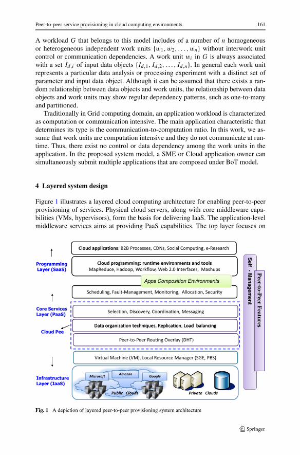
4 Layered system design
Figure 1 illustrates a layered cloud computing architecture for enabling peer-to-peerprovisioning of services. Physical cloud servers, along with core middleware capa-bilities (VMs, hypervisors), form the basis for delivering IaaS. The application-levelmiddleware services aims at providing PaaS capabilities. The top layer focuses on
Fig. 1 A depiction of layered peer-to-peer provisioning system architecture

162 R. Ranjan, L. Zhao
application services (SaaS) by making use of services provided by the lower lay-ers. PaaS/SaaS services are often developed and provided by the 3rd party serviceproviders, who may or may not be different from IaaS providers.
Cloud applications (SaaS): Popular cloud applications include Business to Busi-ness (B2B) applications, traditional eCommerce type of applications, enterprise busi-ness applications such as CRM and ERP, social computing such as Facebook andMySpace, and compute, data intensive applications and Content Delivery Networks(CDNs). This layer also includes the software environments and programming frame-works such as Web 2.0 Interfaces (Ajax, IBM Workplace, and Visual Studio.netAzure plug-in) that help developers in creating rich, cost-effective, user-interfacesfor browser-based applications. The layer also provides the data intensive, parallelprogramming environments (such as MapReduce, Hadoop, Dryad) and compositiontools that ease the creation, deployment, and execution of applications in clouds.
Core Services Layer (PaaS): This layer implements the platform level servicesthat provide runtime environment-enabling cloud computing capabilities to applica-tion services built using User-Level Middlewares. Core services at this layer includeScheduling, Fault-Management, Monitoring, Dynamic SLA Management, Account-ing, Billing, and Pricing. Further, the services at this layer must be able to providesupport for decentralized load-balancing, scalable selection, and messaging betweendistributed cloud components. Some of the existing services operating at this layerare Amazon EC2’s CloudWatch and Load-balancer service, Google App Engine, Mi-crosoft Azure fabric controller, and Aneka. To be able to provide support for decen-tralized service discovery [20] and load-balancing between cloud components (VMinstances, application services); novel Distributed Hash Table (DHT)-based PaaSlayer services need to be developed at this layer for supporting complex interactionswith guarantees on dynamic management. In Fig. 1, this component of PaaS layer isshown as cloud peer service.
Infrastructure Layer (IaaS): The computing power in cloud computing environ-ments is supplied by a collection of data centers that are typically installed with manythousands of servers. At the IaaS layer there exists massive physical servers (storageservers and application servers) that power the data centers. These servers are trans-parently managed by the higher level virtualization services and toolkits that allowsharing of their capacity among virtual instances of servers. These virtual machines(VMs) are isolated from each other, which aids in achieving fault tolerant behaviorand the isolation of security contexts.
5 The peer-to-peer provisioning approach
In this paper, we consider a service provisioning approach that involves followingstages: (i) Discovery, the process of locating an appropriate application service in aloosely-networked overlay of services that can successfully serve an user’s requestunder given constraints/targets (type, availability, location, performance constraints)

Peer-to-peer service provisioning in cloud computing environments 163
and (ii) Load-balancing, which is an act of uniformly distributing workload acrossone or more service instances, in order to achieve performance targets such as max-imize resource utilization, maximize throughput, minimize response time, minimizecost, and maximize revenue. Although resource discovery and load-balancing arewidely studied problems in distributed systems (grid computing, data centers), moreadvanced techniques and algorithms that cater for higher level of decentralization,scalability, and self-management need to be developed.
In effect, end-users for an application service could initiate request from any partof the Internet (in other words end-users are geographically and topologically dis-tributed). Similarly, the system size can vary based on popularity of application ser-vice and performance requirements. Further, as clouds become ready for mainstreamacceptance, scalability of services will come under more severe scrutiny since at thattime cloud providers will have to support an increasing number of online services,each being accessed by massive numbers of global users round the clock. Tradi-tional way of discovering and mapping requests (stage 2) across services based oncentralized network models is inefficient due to scalability, performance, and relia-bility concerns arising from large system size and volume of service requests. Thus,scalable and decentralized approaches that are self-managing must be developed toaccomplish tasks at different stages (stage 1 & 2).
5.1 Query types and their composition
To an extent, the multilayered (IaaS, PaaS, and SaaS) architecture of cloud comput-ing environments (refer to Fig. 2) complicates the overall service discovery problem.At each layer, cloud offers heterogeneous mix of services that differ in their scale,granularity, and type. At IaaS layer, cloud offers services such as physical servers,VMs, storage devices. The search dimensions at IaaS layer can include processorspeed, number of cores, processor architecture, installed operating system, availablememory, and network bandwidth. At SaaS-level, SaaS providers can effectively de-ploy multiple types of services (and/or multiple instance of same service) based onthe composition and predicted workload of the application. For instance, a SaaSprovider, who hosts a business workflow (such as ERP, CRM) can simultaneouslycreate multiple instances of different services (such as application server, databaseserver, security server, etc.) to meet its workload demands. The main challenge fora Service Aggregation Engine (Service Provisioner) is to appropriately select the setof services across workflow such that end-to-end performance targets are met (e.g.,minimize response, maximize service throughput).
A query at SaaS-level must search for services that satisfy multiple criteria in-cluding Service type, price, hosting location, and availability. For example, basedon recent information published by Amazon EC2 CloudWatch service, each Ama-zon Machine Image (AMI) instance has seven performance metrics (see Table 2) andthree dimensions (see Table 3) associated with it. To summarize, a service discoveryquery would be a conjunction of sub-queries that needs to be resolved across multiplesearch dimensions of IaaS and Saas. An example of such a query follows:
Cloud Service Type = web hosting && Host CPU Utilization ≤ 50% && InstanceOSType = WinSrv2003 && Host Processor Cores ≥ 1 && Host Processors Speed≥ 1.5 GHz && Host Cloud Location = Europe

164 R. Ranjan, L. Zhao
Fig. 2 Visual representation of mapping SaaS to logical PaaS-level overlay and IaaS-level physical Cloudservers
Table 2 Performance metrics associated with an Amazon EC2 AMI instance
Utilization IncomingTraffic OutgoingTraffic DiskWriteOps
DiskReadBytes DiskReadOps DiskWriteBytes
Table 3 Performance dimensions associated with an Amazon EC2 AMI instance
Image-ID AutoScalingGroupName InstanceID InstanceType
On the other hand, service instances deployed on physical Cloud services needsto publish their information so that service provisioner can search them. Service in-stances update their software and hardware configuration and the availability statusby sending update query. The service configuration distribution in three dimensionsis shown in Fig. 3. A service update query has the following semantics:
Cloud Service Type = web hosting && Host CPU Utilization = 30% && InstanceOSType = WinSrv2003 && Host Processor Cores = 2 && Host Processors Speed= 1.5 GHz && Host Cloud Location = Europe
5.2 Cloud peer service design
The cloud peer implements services for enabling decentralized and distributed dis-covery supporting status lookups and updates across the internetworked cloud com-

Peer-to-peer service provisioning in cloud computing environments 165
Fig. 3 SaaS Services types and Update query distribution
puting system components; enabling optimizing load-balancing and tackling the dis-tributed service contention problem. Dotted box in Fig. 1 shows the layered designof cloud peer service over DHT based self-organizing routing structure. The servicesbuild upon the DHT routing structure extends (both algorithmically and programmat-ically) the fundamental properties related to DHTs including deterministic lookup,scalable routing, and decentralized network management. The cloud peer service isdivided into a number of sublayers (see Fig. 1): (i) higher level services for discovery,coordination, and messaging; (ii) low level distributed indexing and data organizationtechniques, replication algorithms, and query load-balancing techniques; (iii) DHT-based self-organizing routing structure. A cloud peer undertakes the following criticaltasks that are important for proper functioning of DHT-based provisioning overlay:
5.2.1 Overlay construction
The overlay construction refers to how cloud peers are logically connected overthe physical network. The system design approach utilizes FreePastry [5] (a opensource implementation of Pastry DHT) as the basis for creation of cloud peer over-lay. A Pastry overlay inter-connects the cloud peer services based on a ring topology.Inherent to the construction of a Pastry overlay are the following issues: (i) Gener-ation of cloud peer ids and query (discovery, update) ids, called keys, using crypto-graphic/randomizing hash functions [7, 20, 27] such as SHA-1. These ids are gen-erated from 160-bit unique identifier space. The id is used to indicate a cloud peersposition in a circular id space, which ranges from 0 to 2160−1. The queries and cloudpeers are mapped on the overlay network depending on their key values.
Each cloud peer is assigned responsibility for managing a small number of queriesand building up routing information (leaf set, routing table, and neighborhood set) atvarious cloud peers in the network. Given the Key k, Pastry routing algorithm can findthe cloud peer responsible for this key in O(logb n) messages, where b is the base and

166 R. Ranjan, L. Zhao
n is the number of cloud peers in the network. Each cloud peer in the Pastry overlaymaintains a routing table, leaf set, and neighborhood set. These tables are constructedwhen a cloud peer joins the overlay, and it is periodically updated to take into accountany new joins, leaves, or failures. Each entry in the routing table contains the IPaddress of one of the potentially many cloud peers whose id have the appropriateprefix; in practice, a cloud peer is chosen, which is close to the current peer, accordingthe proximity metric. Figure 4 shows a hypothetical Pastry overlay with keys andcloud peers distributed on the circular ring based on their cryptographically generatedids.
5.2.2 Multi-dimensional query indexing
A 1-dimensional hashing provided by a standard DHT is insufficient to manage com-plex objects such as resource tickets and claims. DHTs [8] generally hash a givenunique value (e.g., a file name) to a 1-dimensional DHT key space and hence theycannot directly support mapping and lookups for complex objects. Management ofthose queries whose extents lie in d-dimensional space can be done by embedding alogical index structure over the 1-dimensional DHT key space.
In order to support multidimensional query indexing (service type, host utilization,VM instance OS type, host cloud location, host processor speed) over Pastry overlay,a cloud peer implements a distributed indexing algorithm, which is a variant of peer-to-peer MX-CIF Quad tree distributed indexing algorithm [36]. The distributed index-ing algorithm builds a multi-dimensional index based on the cloud service attributes,where each attribute represents a single dimension. An example 2-dimensional at-tribute space that indexes service attributes including Speed and CPU Type is shownin Fig. 4.
First step in initializing the distributed index is the process called Minimum Di-vision (fmin). This process divides the attribute space into multiple index cells whenthe multi-dimensional distributed index is first created. As a result of this process,the attribute space resembles a grid like structure consisting of multiple index cells.The cells resulting from this process remain constant throughout the life of the in-dexing domain and serve as entry points for subsequent service discovery and updatequery mapping. The number of cells produced at the minimum division level is al-ways equal to (fmin)
dim, where dim is dimensionality of the attribute space. Everycloud peer in the network has basic information about the attribute space coordi-nate values, dimensions and minimum division level. Cloud peers can obtain thisinformation (cells at minimum division level, control points) in a configuration filefrom the bootstrap peer. Each index cell at fmin is uniquely identified by its centroid,termed as the control point. In Fig. 4, fmin = 1, dim = 2. The Pastry overlay hashingmethod (DHT(coordinates)) is used to map these control points so that the respon-sibility for an index cell is associated with a cloud peer in the overlay. For examplein Fig. 4, DHT(x1, y1) = k10 is the location of the control point A(x1, y1) on theoverlay, which is managed by cloud peer 12.
5.2.3 Multi-dimensional query routing
This action involves the identification of the index cells at minimum division levelfmin in the attribute space to map a service discovery and update query. For mapping
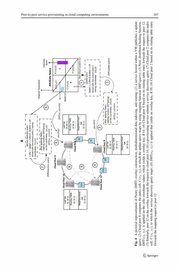
Peer-to-peer service provisioning in cloud computing environments 167
Fig
.4A
pict
oria
lre
pres
enta
tion
ofPa
stry
(DH
T)
over
lay
cons
truc
tion,
mul
tidim
ensi
onal
data
inde
,and
rout
ing:
(1)
ase
rvic
eho
sted
with
ina
VM
publ
ishe
sa
upda
tequ
ery;
(2)
Clo
udpe
er8
com
pute
sth
ein
dex
cell,
C(x
3,y
3),
tow
hich
the
upda
tequ
ery
map
sby
usin
gm
appi
ngfu
nctio
nSM
F(q
uery
);(3
)N
ext,
dist
ribu
ted
hash
ing
func
tion,
DH
T(x
3,y
3),
isap
plie
don
the
cells
coor
dina
teva
lues
,whi
chyi
elds
aov
erla
yke
y,K
14;
(4)
Clo
udpe
er8
base
don
itsro
utin
gta
ble
entr
yfo
rwar
dsth
ere
ques
tto
peer
12;
(5)
Sim
ilarl
y,pe
er12
onth
eov
erla
yfo
rwar
dsth
ere
ques
tto
clou
dpe
er14
;(6)
apr
ovis
ioni
ngse
rvic
esu
bmits
ase
rvic
edi
scov
ery
quer
y;(7
)C
loud
peer
2co
mpu
tes
the
inde
xce
ll,C
(x1,y
1),
tow
hich
the
serv
ice
disc
over
yqu
ery
map
s;(8
)D
HT(x
1,y
1)
isap
plie
dth
atyi
elds
anov
erla
yke
y,K
10;
(9)
Clo
udpe
er2
base
don
itsro
utin
gta
ble
entr
yfo
rwar
dsth
em
appi
ngre
ques
tto
peer
12

168 R. Ranjan, L. Zhao
Algorithm 1: Query routing algorithm undertaken by cloud peer service
Input : discovery di,j , update ui0.1
Output : mapping of objects to cloud peers0.2
Definitions :0.3
– SMF (query): returns set C of base index cells towhich a query maps;
– DHT (control point): returns the key which acts asthe basis of mapping query to Pastry overlay;
– C: set that stores the coordinates for base index cellsto which a query is mapped to;
– key: an m-bit identifier generated from 2m space, forms the basis for determin-istic routing;
– put: sends the messages to appropriate peer using Pastry method. Thismethod is exposed by FreePastry framework;
Procedures :
Post () : map query0.4
Input : query ∈ { discovery, update }0.5
call Route (di,j );0.6
return ;0.7
Route () : route query0.8
Input : query ∈ { discovery, update }0.9
Intialization: C ← { φ }, key ← null0.10
C = SMF(query);0.11
foreach {x,y,z } ∈ C do0.12
key = DHT ({ x,y,z });0.13
call put (key);0.14
end0.15
return ;0.16
service discovery query, the mapping strategy depends on whether it is a multidimen-sional point query (equality constraints on all search attribute values) or multidimen-sional range query. For a multi-dimensional point service discovery query the map-ping is straight forward since every point is mapped to only one cell in the attributespace. For a multidimensional, mapping is not always singular because a range look-up can cross more than one index cell. To avoid mapping a multidimensional servicediscovery query to all the cells that it crosses (which can create many unnecessaryduplicates) a mapping strategy based on diagonal hyperplane of the attribute space isutilized.
Algorithm 1 shows pseudo code for query routing. This mapping involves feed-ing the service discovery query’s spatial dimensions into a mapping function,SMF(query) (see line 0.11 in Algorithm 1). This function returns the IDs of index

Peer-to-peer service provisioning in cloud computing environments 169
cells to which given query can be mapped (refer to step 7 in Fig. 4. Distributed hash-ing (DHT(coordinates)) is performed on these IDs (which returns keys for Pastryoverlay) to identify the current cloud peers responsible for managing the given keys.A cloud peer service uses the index cell(s) currently assigned to it and a set of knownbase index cells obtained at the initialization as the candidate index cells. Similarly,mapping of update query also involves the identification of the cell in the attributespace using the same algorithm. A update query is always associated with an eventregion and all cells that fall fully or partially within the event region would be selectedto receive the corresponding objects. The calculation of an event region is also basedupon the diagonal hyperplane of the attribute space. Giving in depth information hereis out of the scope for this paper, however the readers who would like to have moreinformation can refer the paper that describes the index in detail.
5.3 Load-balancing algorithm description
A load-balanced provisioning of requests between virtual machine instances de-ployed in clouds is critical, as it prevents the service provisioner from congesting theparticular set of VMs and network links, which arises due to lack of complete globalknowledge. In addition, it significantly improves the cloud user Quality of Service(QoS) satisfaction in terms of response time. The cloud peer service in conjunctionwith the Pastry overlay and multi-dimensional indexing technique is able to performa load-balanced service provisioning. The description of the actual load-balancingmechanism follows next.
As mentioned in previous section, both service discovery (issued by service provi-sioner) and update query (published by VMs or Services hosted within VMs) queriesare spatially hashed to an index cell i in the multidimensional attribute space. InFig. 5, service discovery query for provisioning request P1 is mapped to index cellwith control point value A, while for P2, P3, and P4, the responsible cell has controlpoint value C. Note that these service discovery queries are posted by service provi-sioners. In Fig. 5, a provisioning service inserts a service discovery query with cloudpeer p, which is mapped to index cell i. The index cell i is spatially hashed throughrouting functions (refer to Algorithm 1) to an cloud peer s. In this case, cloud peer sis responsible for balancing the load offered by the service discovery queries that arecurrently mapped to the cell i. Subsequently, service si hosted within VM u issuesa update query (see Fig. 5) that falls under a region of the attribute space currentlyrequired by the requests P3 and P4. Next, the cloud peer s has to decide which ofthe requests (either P3 or P4 or both) is allowed to claim the update query publishedby si . The load-balancing decision is based on the principle that it should not lead toover-provisioning of the concerned service. This mechanism leads to load-balancedallocation of work units across services in clouds and aids in achieving system-wideobjective function.
The examples in Table 4 are list of service discovery queries that are stored witha cloud peer service at time T = 700 secs. Essentially, the queries in the list arrivedat a time ≤ 700 and waited for a suitable update query that can meet their provi-sioning requirements (software, hardware, service type, location). Table 5 depictsan update query that has arrived at T = 700. Following the update query arrival, the

170 R. Ranjan, L. Zhao
Fig
.5Pe
er-t
o-pe
erpr
ovis
ioni
ngac
ross
serv
ice
inst
ance
s.M
ulti-
dim
ensi
onal
serv
ice
prov
isio
ning
requ
ests
P1,P
2,P3
,P4,
inde
xce
llco
ntro
lpoi
nts
A,B
,C,D
,mul
ti-di
men
-si
onal
upda
tequ
erie
sl,
san
dso
me
ofth
esp
atia
lha
shin
gsto
the
Past
ryov
erla
y,i.e
.the
mul
ti-di
men
sion
al(s
patia
l)co
ordi
nate
valu
esof
ace
ll’s
cont
rol
poin
tis
used
asth
ePa
stry
key.
For
this
figur
ef
min
=2,
dim
=2

Peer-to-peer service provisioning in cloud computing environments 171
Table 4 Service discoveryquery stored with a cloud peerservices at time T
Time Query ID Service type Speed Cores Location
300 Query 1 Web Host-1 > 2 1 USA
400 Query 2 Web Host-2 > 2 1 Singapore
500 Query 3 Web Host-3 > 3 1 Europe
Table 5 A representative Update query published with a cloud Peer service at time T
Time VM IP Service type Speed Cores Utilization Location
700 192.168.128.127 Web Host-1 > 2.7 1 70% USA
cloud peer service undertakes a procedure that allocates the available service capacitywith si (that published the update query) among the list of matching service discov-ery queries. Based on the updating si ’s attribute specification, only service discoveryquery 3 matches. Following this, the cloud peer notifies the provisioning services thatposted the Query 1. Note that Queries 2 and 3 have to wait for the arrival of updatequeries that can match their requirements.
5.3.1 Load-balancing algorithm analysis
This section analyzes the computational tractability of the approach by deriving sev-eral time and message complexity bounds to measure the computational quality. Us-ing the example for embarrassingly parallel or Bag of Tasks application models, weanalyze the time complexity involved with mapping a service request for a task to aservice si in the overlay. A service request is encapsulated as a discovery query and isinjected to the cloud peer overlay using the Algorithm 1. A concise description of theimportant steps involved with the load-balancing process is shown in Algorithm 2.
We consider a peer-to-peer overlay of cloud-based n services (SaaS-level) and m
independent requests that are required to be mapped to one of these services in aload-balanced manner. This implies that there are total m requests that are submittedby application provisioners (on-behalf of end-users) to the peer-to-peer overlay.
When a discovery query, di,j arrives at a cloud peer, it is added to the existingquery list (see lines 1.17–1.21 in Algorithm 2). When a update query, ui arrives (referto lines 1.22–1.32 in Algorithm 2) at a cloud peer, the list of discovery queries thatoverlap or match (refer to lines 1.6–1.16 in Algorithm 2) with the submitted updatequery in the d-dimensional space is computed. The overlap signifies that the servicerequests associated with discovery queries can be served by the update query issuerservice, subject to its availability.
In order to compute a load-balanced mapping for requests to services, the cloudpeer first, selects the discovery queries stored in the QueryList (see line 1.19 in Algo-rithm 2) in first come first serve order (see line 1.12 in Algorithm 2); then from thislist, the number of discovery queries that overlap with a update query is stored in theQueryListm (see line 1.12 of Algorithm 2). The service requests related to the dis-covery queries are mapped to the service si until that service is not over-provisioned

172 R. Ranjan, L. Zhao
Algorithm 2: Load-balancing undertaken by a cloud peer in the overlay
Input : discovery di,j , update ui1.1
QueryList ← Φ ;1.2
index ← 0 ;1.3
Output : load-balanced mapping1.4
Definitions :1.5
– Overlap (discovery di,j , update ui ): returns true if discovery query di,j
matches against the update query ui ;– QueryList: stores the list of discovery queries currently mapped to a cloud
peer i;– QueryListm: stores the list of discovery queries that matches against a currently
published update query ui ;
Procedures() :
Match(di,j , ui ) :1.6
Input : discovery di,j , update ui1.7
index ← 0 ;1.8
QueryListm ← Φ ;1.9
foreach discovery di,j ∈ QueryList do1.10
if Overlap (discovery di,j , update ui ) �= Φ then1.11
QueryListm ← QueryListm [indexm ] ∪ di,j ;1.12
indexm ← indexm + 1 ;1.13
end1.14
end1.15
return(QueryListm) ;1.16
Discovery Query Arrival(di,j ):1.17
Input : discovery di,j1.18
QueryList [index ] ← ∪ di,j ;1.19
indexm ← indexm + 1 ;1.20
return;1.21
Update Query Arrival(ui ) :1.22
Input : update ui from service si1.23
QueryListm ← Φ ;1.24
QueryListm ← Match(di,j , ui ) ;1.25
counter ← SizeOf (QueryListm) ;1.26
while si is not over-provisioned OR counter ≥ 0 do1.281.28
map reqeust QueryListm [counter ] to si ;1.29
counter ← counter + 1 ;1.30
end1.31
return;1.32

Peer-to-peer service provisioning in cloud computing environments 173
(lines 1.28–1.30 in Algorithm 2). In worst case, QueryList in Algorithm 2 can containm number of discovery queries and all of them could potentially match to a updatequery, ui . Hence, in this case, complexity involved with calculating (lines 1.11–1.14)the match list and mapping (lines 1.28–1.31) of requests to services is O(m).
The load-balancing procedure can utilize the dynamic resource parameters such asthe number of available processors, queue length, etc. as the over-provision indicator.These over-provision indicators are encapsulated in the update query object by theservices. The next section describes the overall message complexity involved withAlgorithm 1 and Algorithm 2.
5.4 Message complexity analysis
Lemma 1 In a overlay of n heterogeneous services, on average a service request di,j
requires O(logn) messages to be sent in order to locate a service that can success-fully complete the request without being overloaded.
Mapping a service request, which is encapsulated in a discovery query messagedi,j , involves the following steps: (i) posting a discovery query the cloud peer overlayand (ii) mapping the service request to the matching service (refer to Algorithm 2).Hence, the total number of messages produced in successfully allocating a request toa service is summation of the number of messages produced in these two steps. Inrest of this discussion, the terms discovery query and service request are used inter-changeably.
We denote the number of messages generated in mapping a service request di,j bya random variable Mc. The distribution of Mc is function of the problem parametersincluding query size, dimensionality of search space, query rate, division threshold,and data distribution. Note that the derivation presented in this paper assumes that thePastry method is used for delegation of service messages in the overlay. Essentially,a control point at the fmin level of the logical d-dimensional Cartesian space can bereached in O(logb n) routing hops using the Pastry routing method (see lines 0.11–0.15 in Algorithm 1). Based on the above discussion, in order to compute the worstcase message lookup and routing complexity one additional random variable Tdi,j
isconsidered. Tdi,j
denotes the number of disjoint query path undertaken in mappinga discovery query. The d-dimensional index described in Sect. 5.2 maps a servicerequest to utmost mapped to 2 index cells. Note that the number of index cells towhich a service request can be mapped is dependent on the spatial index. With PastryDHT method every disjoint path will undertake E[Tdi,j
]× (logb n) routing hops withhigh probability. Hence, the expected value of Mdi,j
is given by:
E[Tdi,j] = E[Mdi,j
] × (logb n),
substituting E[Tdi,j] with the value 2 and adding 1 for messages involved with actual
mapping,
E[Mdi,j] = 2 × (logb n) + 1,
ignoring the constant terms in the above equation we get,
E[Mdi,j] = O(logn). (1)
174 R. Ranjan, L. Zhao
The above equation shows that mapping message complexity function growth rateis bounded by the function O(logn).
Lemma 2 In a overlay of n services and total m service requests, the total mappingmessages (see lines 0.11–0.16 in Algorithm 1) generated in the system is bounded bythe function O(m × n × logn).
This lemma directly follows from definition of Algorithm 1. Since a service inthe system requires O(logn) messages to be undertaken before it can be successfullyallocated to service, therefore computing the mapping message complexity for m
requests is straightforward.
Lemma 3 In a overlay of n heterogeneous services, each service posts p updatequery over a time period t , then the average-case message complexity involved withmapping (refer to lines 0.11–0.16 in Algorithm 1) these update queries to cloud peersin the overlay is bounded by the function O(E[Tui
] × p × logn).
The proof for this definition directly follows from Lemma 1. The procedure formapping the update query to cloud peers is similar to the one followed for a discoveryquery. A update query is always associated with an event region, and all index cellsthat fall fully and partially within the even region will be selected to receive thecorresponding update query. The number of disjoint query path taken to map a updatequery is denoted by random variable Tui
with mean E[Tui].
6 Experiments and evaluation
In this section, we evaluated the performance of the proposed peer-to-peer cloud pro-visioning approach (cloud peer) by creating a overlay of services that are deployedacross virtual machines within the Amazon EC2 infrastructure. We assumed unsatu-rated server availability for these experiments, so that enough capacity could alwaysbe allocated to a VM for any service request. Next, we describe the various detailsrelated to cloud Peer (peer-to-peer network, multidimensional index structure, andnetwork configuration parameters) setup, PaaS layer provisioning software, and ap-plication model related to this study.
6.1 Cloud peer details
A cloud peer service operates at PaaS (refer to Fig. 4) layer and handles activi-ties related to decentralized query (discovery and update) routing, management, andmatching. Additionally, it also implements the higher level services such as pub-lish/subscribe based loosely-coupled interactions and service selections. Every VMinstance, which is deployed on the Amazon EC2 platform, hosts a number of servicesand a cloud peer service that loosely glues it to the overlay. Next, follows the detailsrelated to the configuration of cloud peer.
FreePastry [5] network configuration: Both cloud peers’ nodeIds and discov-ery/update queries’ overlay IDs were randomly generated from the 160-bit Pastry

Peer-to-peer service provisioning in cloud computing environments 175
identifier space. These nodeIds and overlay IDs were uniformly distributed in theidentifier space. Every cloud peer service was configured to buffer maximum of1,000 messages at a given instance of time. The buffer size was chosen to be suf-ficiently large such that the FreePastry framework did not drop any messages. Othernetwork parameters were configured tp the default values as given in the file freepas-try.params. This file is generally provided with the FreePastry distribution.
Multidimensional index configuration: The minimum division fmin of logicalmulti-dimensional index was set to 3, while the maximum height of the distributedtree (multi-dimensional index), fmax was constrained to 3. In other words, the di-vision of the multi-dimensional attribute space was not allowed beyond fmin. Thisis done for keeping the setup simple and easy to configure. The multidimensionalindex tree (space) had provision for defining service discovery and update queriesthat specify the service characteristics in 4 dimensions including application servicetypes, number of processing cores available on the server hosting the VM, hardwarearchitecture of the processor(s), and their processing speed. The aforementioned mul-tidimensional index configuration results into 81(34) index cells at fmin level.
Service discovery and update queries multi-dimensional extent: Update queries,which are posted by service instances, express equality constraints on its type, in-stalled software environments, and hardware configuration attribute values (e.g., =).
6.2 Aneka: PaaS layer application provisioning and management service
At PaaS layer, we utilize the Aneka [11] software framework that handles activi-ties related to application element scheduling, execution, and management. Aneka isa .NET-based service oriented platform for constructing cloud computing environ-ments. To create a cloud application provisioning systems using Aneka, a developeror application scientist needs to start an instance of the configurable Aneka containerhosting required services on each selected VMs.
Services of Aneka can be broadly characterized into two distinct spaces: (i) Ap-plication Provisioner: This service implements the functionality that: (i) accepts ap-plication workload from cloud users; (ii) performs dynamic discovery of applica-tion management services via the cloud peer service; (iii) dispatches workload toapplication management service; (iv) monitors the progress of their execution; and(v) collects the output data, which returned back to the cloud users. An ApplicationProvisioner need not be hosted within a VM; it only needs to know the endpoint ad-dress (such as web service address) of a random cloud peer service in the overlayto which it can connect and submit its service discovery query; and (ii) ApplicationManagement Service: This service, which is hosted within a VM, is responsible forhandling execution and management of submitted application workload. An applica-tion management service sits within a VM and updates its usage status, software, andhardware configurations by sending update queries to the Cloud peer overlay. One ormore instance of application management service can be connected in a single-levelhierarchy to be controlled by a root level Application Provisioner. This kind of ser-vice integration is aimed at making application programming flexible, efficient, andscalable.

176 R. Ranjan, L. Zhao
6.3 Test application
The PaaS layer software service, Aneka, supports composition, orchestration, andexecution of application programs that are composed using different application pro-gramming models to be executed within the same software environment. The experi-mental evaluation in this paper considers execution of applications programmed usingthread model. The thread programming model defines an application as a collectionof one or more independent work units. This model can be successfully utilized tocompose and program embarrassingly parallel programs (parameter sweep applica-tions). The thread model fits well for implementing and architecting new applications,algorithms on cloud infrastructures since it gives finer degree of control and flexibilityas regards to runtime control.
To demonstrate the feasibility of architecting cloud provisioning services basedcloud peer overlay, we consider composition and execution of Mandelbrot Set com-putation. Mathematically, the Mandelbrot set is an ordered collection of points inthe complex plane, the boundary of which forms a fractal. The Application Provi-sioner service implements and enables the Mandelbrot fractal calculation on cloudresources, using a the thread programming model. The application submission in-terface allows the end-users to configure number of horizontal and vertical partitionsinto which the fractal computation can be divided. These horizontal and vertical parti-tions, we refer to as problem complexity. The number of independent thread units cre-ated is equal to the horizontal×vertical partitions. For evaluations, we vary the valuesfor horizontal and vertical parameters over the intervals, 5 × 5, 10 × 10, 15 × 15, and20 × 20.
6.4 Deployment of test services on amazon EC2 platform
In order to test the feasibility of aforementioned services in regards to the provision-ing of application services on Amazon EC2 cloud platform, we created Amazon Ma-chine Images (AMIs) packaged with a cloud peer, Aneka’s Application Provisionerand Management services. The image that hosted the cloud peer and Aneka Provi-sioner services was equipped with Microsoft Windows Server 2008 R1 SP2 Data-center edition, Microsoft SQL Server 2008 Express, Internet Information Services 7,Tomcat 6.0.10, and Axis2 1.2 container. On the other hand, while the image thathosted the Aneka Management Service had Microsoft Windows Server 2008 R1 SP2Datacenter system installed, cloud peer service was exposed to the provisioning andmanagement services through WS* interfaces. Later, we built the customized Ama-zon Machine Images from the aforementioned basic images. We configured threeApplication Provisioners and nine Management Services. The Management Servicewas divided into groups of three that connected to a common Application Provisioner,this resulted in a hierarchical structure. The Application provisioner services commu-nicate and internetwork through the cloud peer overlay. Figure 6 shows the pictorialrepresentation of the test service setup.
6.5 Results and observations
In this study: (i) the problem complexity was varied over the range 5 × 5, 10 × 10,15 × 15, and 20 × 20; (ii) heartbeat interval was selected from the following set of

Peer-to-peer service provisioning in cloud computing environments 177
Fig. 6 Test service setup in Amazon EC2
values 1, 10, and 60 seconds; and (iii) the minimum division was selected from theinterval [2, 4] in step of 1. The graphs in Figs. 7, 8, and 9 show the performance of thepeer-to-peer cloud provisioning techniques (service discovery & load-balancing) interms of problem complexity, heartbeat interval, and minimum division perspective,respectively.
All the application workload were concurrently submitted to the Application Pro-visioners. Several metrics were quantified for identifying the performance of peer-to-peer cloud provisioning techniques, including response time, query mapping delay,and cloud peer overlay network message complexity for routing multi-dimensionalqueries. The response time for an application was calculated by subtracting the out-put arrival time of the last thread in the submission list from the time at which theapplication was originally submitted. On the other hand, cloud peer overlay messagecomplexity measures the finer details related number of messages that flow throughthe network in order to: (i) initialize the multidimensional attribute space, (ii) mapthe discovery and update queries, (iii) maintain the overlay, and (iv) send notifica-tions. The metric mapping delay measures the average latency for mapping a servicediscovery query to a cloud peer.
6.5.1 Problem complexity perspective
Figure 7 shows the results for response time in seconds, number of tasks and mes-sages, as well as mapping delay with increasing problem complexity size. Cloud con-sumers submit their applications with a Application Provisioner (see Fig. 6). The ini-tial experimental results in Fig. 7(a) and Fig. 7(b) reveal that with increase in problemcomplexity (number of horizontal × vertical partitions of Madelbrot set), the appli-cation end-users experience increase in response times and mapping delay. The basic

178 R. Ranjan, L. Zhao
Fig. 7 The performance of the peer-to-peer cloud provisioning techniques with varying problem com-plexity. The heartbeat interval was set to 2 seconds and fmin and fmax to 3, for these set of experiments
reason behind this behavior of the cloud system was the fixed number ApplicationManagement services (static infrastructure capacity), i.e., with increase in the prob-lem complexity, the number of task threads (a task thread represents a single workunit, e.g., for 5 × 5 Mandelbrot configuration resulted in creation of 25 task threads)that are required to be serviced with Management services increase, hence leadingto worsening queuing and waiting delays. However, this behavior of the system canbe fixed through implementation of reactive provisioning of new service instances tocounter the effect of increase in problem complexity or size.

Peer-to-peer service provisioning in cloud computing environments 179
Fig. 8 The performance of the peer-to-peer cloud provisioning technique in terms of heartbeat intervalperspective with problem complexity size as 15 × 15 and fmin and fmax as 3
Figure 7(b) presents the measurements for average mapping delay for each discov-ery query with respect to increase in the problem complexity. The results show that athigher problem complexity, the discovery queries experience increased mapping de-lay. This happens due to the reason that the discovery queries have to wait for longerperiod of time before they are matched against an update query (service contentionproblem). However, the task thread processing time (CPU time) is not affected bythe mapping delay, hence the response time in Fig. 7(a) shows no or little change fordifferent problem sizes.
Figure 7(c) indicates the total number completed tasks at each Aneka’s Applica-tion Management service instance with the increase in problem complexity. For everygroup of problem complexity, the number of tasks at each instance showed a similartrend. The result shows that the task processing load was evenly distributed across themanagement service instances. This behavior basically proved that the load-balancingalgorithm undertaken by cloud peer services was extremely effective distributing theworkload across services instances.
Figure 7(d) shows the total message overhead involved with management of mul-tidimensional index, routing of discovery(marked as sub Fig. 7(d)) and update query(marked as pub) messages, and maintenance of Pastry overlay. We can clearly seethat as problem complexity increases the number of messages required for mappingthe queries to the overlay network increase as well. The number of discovery andupdate messages produced in the overlay is a function of the multidimensional indexstructure that maintains and routes these queries in a peer-to-peer fashion. In addi-tion, from Fig. 7(d), it is evident that our system is scalable since the total number
180 R. Ranjan, L. Zhao
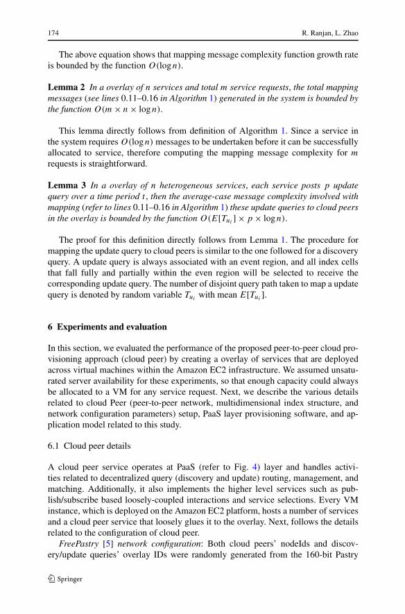
Fig. 9 The performance of the peer-to-peer cloud provisioning technique in terms of maximum divisionperspective with problem complexity size as 15 × 15, heartbeat interval as 2 seconds and fmax as 5
of messages is increased linearly with respect to problem size. Hence, the choice ofthe multidimensional data indexing structure and routing technique governs the man-ageability and efficiency of the overlay network (latency and messaging overhead).Hence, there is much work required in this domain as regards to evaluating the per-formance of different types of multidimensional indexing structures for mapping thequery messages in peer-to-peer settings.
The proposed load-balancing approach was also highly successful in reducing thenumber of mapping iterations undertaken for the successful submission of a taskto a Application Management service (see Fig. 7(e)). Note that, our results showedthat the negotiation and notification complexity of the proposed approach had simi-lar bounds as that of a centrally provisioned system, such as the Amazon EC2 load-balancer or Microsoft Fabric Controller. Essentially, with a centrally provisioned sys-tem, the mapping iteration and notification message complexity is O(1). Experimentresults (refer to Fig. 7(e)) showed that Aneka’s Application Provisioner service inthe system receive an average 1 notifications on per task basis. This suggests thatthe mapping iteration and notification complexity involved with our scheduling tech-nique is O(1).
6.5.2 Heartbeat interval perspective
Figure 8 consists of results for group of test that measured the effect of varying heart-beat (update query publish delay) interval on response time, number of messages andmapping delay. The heartbeat interval was varied as 1 second, 10 seconds, and 60
Peer-to-peer service provisioning in cloud computing environments 181
seconds. At the same time, fmin and fmax were set to 3 and the problem complex-ity size was configured to be 15 × 15. The primary results in Fig. 8(a) showed a nearconstant response time behavior, which was around 228 seconds, over three heartbeatintervals.
Figure 8(b) depicts the number of messages generated with respect to increas-ing heartbeat interval. We can see that as heartbeat interval increases, the num-ber of messages generated during the experiment period decrease. For instance,when heartbeat interval was configured to 1 second, the total number of mes-sages produced was 14,974. However, the number of messages dropped signifi-cantly for higher values of heartbeat interval. Figure 8(c) reveals the relationshipof the mapping delay and the heartbeat interval. We can see that with increase inheartbeat interval, the mapping delay increases to some extent. Therefore, the up-date query interarrival delay (heartbeat interval) should be chosen in such a waythat a balance between mapping delay and message overhead can exist in the sys-tem.
6.5.3 Minimum division (fmin) perspective
In this experiment (Fig. 9), we were interested in studying the behavior of responsetime, number of messages and mapping delay parameters with increasing fmin valuefor multi-dimensional index. We can recall that, fmin affects the number of indexcells that created, which subsequently controls the number of messages required formapping queries. For this experiment,fmax was fixed to 5, while the fmin was variedover the interval [2,4] in step of 1. Next, the heartbeat interval was fixed to 2 seconds.The Mandelbrot application problem complexity was set to 15 × 15. Our goal in thisexperiment was to study the effect of fmin on the application response time and querymapping delay.
As shown in Fig. 9(a), with the increase in fmin, we did not observe a significantchange in the average response time. In fact, the response time kept steady when fmin
varies. At fmin = 2, 3 and 4, the response time remains at the value of 226 ± 1.We also analyzed the number of messages that were required to: (i) manage multi-
dimensional index; (ii) route discovery and update query messages; and (iii) maintainPastry overlay with changing fmin. The results for this test is shown in Fig. 9(b). Thenumber of discovery messages (shown as sub in the Fig. 9(b)) remained constant at450. This was because, number of message required for mapping a discovery is inde-pendent of fmin value, as discussed in previous sections. Meanwhile, the number ofupdate query mapping messages were found to be doubling with increase in fmin. Wealso observed that changing fmin value did not affect average mapping delays (referto Fig. 9(b)) of discovery queries. At fmin = 2, the discovery query in the system onaverage experienced a mapping delay of 34,494.65 milliseconds. While at fmin = 4this value increased to 35,000 milliseconds.
The key lesson here is that, fmin value should be chosen in such a way that queryprocessing load is evenly distributed across cloud peers, while having little or notimpact on the application performance. Evaluating this aspect of system is subject ofour future work.

182 R. Ranjan, L. Zhao
7 Conclusion
Developing provisioning techniques that integrate application services in a peer-to-peer fashion is critical to exploiting the potential of cloud computing platforms. Ar-chitecting provisioning techniques based on peer-to-peer network models (such asDHTs) is significant; Since peer-to-peer networks are highly scalable, can gracefullyadapt to the dynamic system expansion (join) or contraction (leave, failure), are notsusceptible to single point of failure. To this end, we presented a software fabriccalled cloud peer that creates an overlay network of VMs and application servicesfor supporting scalable and self-managing service discovery and load-balancing. Thefunctionality exposed by the cloud peer service is very powerful and our experimentalresults conducted on Amazon EC2 platform confirms that it is possible to engineerand design peer-to-peer cloud provisioning systems and techniques.
As part of our future work, we would explore other multidimensional data index-ing and routing techniques that can achieve close to logarithmic bounds on messagesand routing state, balance query (discovery, load-balancing, coordination) process-ing load, preserves data locality, and minimize the metadata. Another important al-gorithmic and programming challenge in building robust cloud peer services is toguarantee consistent routing, lookup, and information consistency under concurrentleave, failure and join operations by application services. To address these issues,we will investigate robust fault-tolerance strategies based on distributed replicationof attribute/query subspaces to achieve a high level of robustness and performanceguarantees.
Acknowledgements Dr. Rajiv Ranjan would like to thank the University of New South Wales for fund-ing his position though the strategic e-Research initiative.
References
1. Amazon auto scaling service (2010) http://aws.amazon.com/autoscaling/. Accessed: May 25, 20102. Amazon cloudwatch service (2010) http://aws.amazon.com/cloudwatch/. Accessed: May 25, 20103. Amazon elastic mapreduce service (2010) http://aws.amazon.com/elasticmapreduce/. Accessed: May
25, 20104. Amazon load balancer service (2010) http://aws.amazon.com/elasticloadbalancing/. Accessed: May
25, 20105. An open source pastry dht implementation (2010) http://freepastry.rice.edu/FreePastry. Accessed:
May 25, 20106. Armbrust M, Fox A, Griffith R, Joseph AD, Katz RH, Konwinski A, Lee G, Patterson DA, Rabkin A,
Stoica I, Zaharia M (2009) Above the clouds: a Berkeley view of cloud computing. Technical ReportUCB/EECS-2009-28, EECS Department, University of California, Berkeley, Feb
7. Bakhtiari S, Safavi-naini R, Pieprzyk J, Centre Computer (1995) Cryptographic hash functions: a sur-vey. Technical report
8. Balakrishnan H, Frans Kaashoek M, Karger D, Morris R, Stoica I (2003) Looking up data in p2psystems. Commun ACM 46(2):43–48
9. Bharambe AR, Agrawal M, Seshan S (2004) Mercury: supporting scalable multi-attribute rangequeries. Comput Commun Rev 34(4):353–366
10. Buyya R, Yeo CS, Venugopal S, Broberg J, Brandic I (2009) Cloud computing and emerging it plat-forms: vision, hype, and reality for delivering computing as the 5th utility. Future Gener Comput Syst25(6):599–616

Peer-to-peer service provisioning in cloud computing environments 183
11. Chu X, Nadiminti K, Jin C, Venugopal S, Buyya R (2007) Aneka: next-generation enterprise gridplatform for e-science and e-business applications. In: E-SCIENCE ’07: proceedings of the third IEEEinternational conference on e-science and grid computing, Washington, DC, USA. IEEE ComputerSociety Press, Los Alamitos, pp 151–159
12. Eucalyptus systems (2010) http://www.eucalyptus.com/. Accessed: May 25, 201013. Force.com cloud solutions (saas) (2010) http://www.salesforce.com/platform/. Accessed: May 25,
201014. Ganesan P, Yang B, Garcia-Molina H (2004) One torus to rule them all: multi-dimensional queries in
p2p systems. In: WebDB ’04: proceedings of the 7th international workshop on the web and databases,New York, NY, USA. ACM Press, New York, pp 19–24
15. Gillett FE, Brown EG, Staten J, Lee C (2008) Future view: the new tech ecosystems of cloud, cloudservices, and cloud computing. Technical report, Forrester Research, Inc
16. GoGrid Cloud Hosting (2010) (f5) load balancer. GoGrid wiki, http://wiki.gogrid.com/wiki/index.php/(F5)-Load-Balancer. Accessed: May 25, 2010
17. Google app engine (2010) http://code.google.com/appengine/. Accessed: May 25, 201018. Gupta I, Birman K, Linga P, Demers Al, van Renesse R (2003) Kelips: building an efficient and stable
p2p dht through increased memory and background overhead. In: Proceedings of the 2nd internationalworkshop on peer-to-peer systems (IPTPS ’03)
19. Gupta A, Sahin OD, Agrawal D, El Abbadi A (2004) Meghdoot content-based publish/subscribeover p2p networks. In: Middleware ’04: proceedings of the 5th ACM/IFIP/USENIX internationalconference on middleware, New York, NY, USA. Springer, New York, pp 254–273
20. Karger D, Lehman E, Leighton T, Panigrahy R, Levine M, Lewin D (1997) Consistent hashing andrandom trees: distributed caching protocols for relieving hot spots on the world wide web. In: STOC’97: proceedings of the twenty-ninth annual ACM symposium on theory of computing, New York,NY, USA. ACM Press, New York, pp 654–663
21. Lee YC, Zomaya A (2010) Rescheduling for reliable job completion with the support of clouds.Future Gener Comput Syst. doi:10.1016/j.future.2010.02.010
22. Li J, Stribling J, Gil TM, Morris R, Frans Kaashoek M (2005) Comparing the performance of dis-tributed hash tables under churn. In: Lecture notes in computer science. Springer, Berlin, pp 87–99
23. Lua EK, Crowcroft J, Pias M, Sharma R, Lim S (2005) A survey and comparison of peer-to-peeroverlay network schemes. IEEE Commun Surv Tutor 7(2):72–93
24. Mosso cloud platform (2010) http://www.rackspacecloud.com. Accessed: May 25, 201025. Openvpn (2010) http://openvpn.net/. Accessed: May 25, 201026. Parashar M, Gnanasambandam N, Quiroz A, Kim H, Sharma N (2009) Towards autonomic workload
provisioning for enterprise grids and clouds. In: Proceedings of the 10 th IEEE/ACM internationalconference on grid computing (Grid 2009), pp 50–57
27. Preneel B (1999) The state of cryptographic hash functions. In: Lectures on data security: moderncryptology in theory and practice, 1994. Lecture notes in computer science, vol 1561. Springer, Berlin,pp 158–182
28. Ranjan R (2007) Coordinated resource provisioning in federated grids. PhD thesis, The University ofMelbourne
29. Ranjan R, Harwood A, Buyya R (2008) Peer-to-peer-based resource discovery in global grids: a tuto-rial. IEEE Commun Surv Tutor 10(2):6–33
30. Ratnasamy S, Francis P, Handley M, Karp R, Shenker, S (2001) A scalable content-addressable net-work. In: SIGCOMM ’01: proceedings of the 2001 conference on applications, technologies, archi-tectures, and protocols for computer communications, New York, NY, USA. ACM Press, New York,pp 161–172
31. Rejila cloud platform (2010) http://www.rejila.com/. Accessed: May 25, 201032. Rochwerger B, Breitgand D, Levy E, Galis A, Nagin K, Llorente IM, Montero R, Wolfsthal Y, Elmroth
E, Caceres J, Ben-Yehuda M, Emmerich W, Galan F (2009) The reservoir model and architecture foropen federated cloud computing. IBM J Res Dev 53(4). http://dl.acm.org/citation.cfm?id=1850659.1850663
33. Rowstron AIT, Druschel P (2001) Pastry: scalable, decentralized object location, and routing for large-scale peer-to-peer systems. In: Middleware ’01: proceedings of the IFIP/ACM international confer-ence on distributed systems platforms heidelberg, London, UK. Springer, Berlin, pp 329–350
34. Spence D, Crowcroft J, Hand S, Harris T (2005) Location based placement of whole distributed sys-tems. In: CoNEXT ’05: proceedings of the 2005 ACM conference on emerging network experimentand technology, New York, NY, USA. ACM Press, New York, pp 124–134

184 R. Ranjan, L. Zhao
35. Stoica I, Morris R, Liben-Nowell D, Karger DR, Frans Kaashoek M, Dabek F, Balakrishnan H (2003)Chord: a scalable peer-to-peer lookup protocol for internet applications. IEEE/ACM Trans Netw11(1):17–32
36. Tanin E, Harwood A, Samet H (2007) Using a distributed quadtree index in peer-to-peer networks.VLDB J 16(2):165–178
37. The S. Reservoir (2008) Reservoir—an ict infrastructure for reliable and effective delivery of servicesas utilities. Technical report, IBM Research
38. Varia J (2009) Cloud architectures. Technical report, Amazon Web Services39. Vpn-cubed (2010) http://www.cohesiveft.com/vpncubed/. Accessed: May 25, 201040. Windows azure platform (2010) http://www.microsoft.com/azure/. Accessed: May 25, 201041. Zhang X, Freschl JL, Schopf JM (2003) A performance study of monitoring and information ser-
vices for distributed systems. In: High performance distributed computing. Proceedings 12th IEEEinternational symposium on, 22–24 2003, pp 270–281


![Peer-to-Peer Cloud Provisioning: Service Discovery and ... · Peer-to-Peer Cloud Provisioning: Service Discovery and Load ... process consists of two key steps [37]: (i) VM Provisioning,](https://static.fdocuments.in/doc/165x107/5b05db957f8b9ad5548c09f5/peer-to-peer-cloud-provisioning-service-discovery-and-cloud-provisioning-service.jpg)