PEEL HERE TO OPEN Quick Start Guide
3
Quick Start Guide ® PEEL HERE TO OPEN 2 COLD WATER CONNECTIONS 3 HOT WATER CONNECTIONS ELECTRIC CONNECTION GAS CONNECTION AIR INTAKE EXHAUST BEFORE YOU BEGIN Gather required additional tools Multi Meter Manometer Combustion Analyzer (optional) SCAN CODE for additional information and videos
Transcript of PEEL HERE TO OPEN Quick Start Guide

Quick Start Guide®
PEEL HERE TO OPEN
2 COLD WATER CONNECTIONS
3 HOT WATER CONNECTIONS
ELECTRICCONNECTION
GAS CONNECTION
AIR INTAKE
EXHAUST
BEFORE YOU BEGINGather required additional tools
Multi Meter ManometerCombustion
Analyzer (optional)
SCAN CODE for additional information and videos
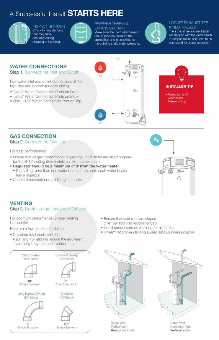
A Successful Install STARTS HERELOCATE EXHAUST TEE & NEUTRALIZER The exhaust tee and neutralizer are shipped with the water heater in a separate box and need to be connected for proper operation.
GAS CONNECTIONStep 2, Connect the Gas Line
For best performance:• Ensure that all gas connections, regulator(s), and meter are sized properly
for the BTU/h rating (See Installation Manual for charts) • Regulator should be a minimum of 8' from the water heater
If installing more than one water heater, make sure each water heater has a regulator
• Check all connections and fittings for leaks
2
PREPARE THERMAL EXPANSION TANK Make sure the thermal expansion tank is properly sized for the application and pressurized to the building static water pressure.
INSPECT SHIPMENT Check for any damage that may have occurred during shipping or handling.
WATER CONNECTIONSStep 1, Connect the Inlet and Outlet
Five water inlet and outlet connections at the top, side and bottom for easy piping• Two 2" Water Connection Ports on Front • Two 2" Water Connection Ports on Back• One 1-1/2" Water Connection Port on Top1
BACK
BACK
x3
x2
TOP
INSTALLER TIP
• Remember to fill water heater before startup
3Short Sweep
90º Elbow
10' Straight Equivalent
8' Straight Equivalent
Standard Sweep 90º Elbow
5' Straight Equivalent
Long Radius Sweep 90º Elbow
2.5' Straight Equivalent
Standard45º Elbow
Direct Vent Vertical VentHorizontal Intake
Direct Vent Horizontal VentVertical Intake
VENTINGStep 3, Hook Up the Intake and Exhaust
For optimum performance, proper venting is essential. Here are a few tips for installation:• Calculate total equivalent feet.
90° and 45° elbows reduce the equivalent vent length by the these values
• Ensure that vent runs are sloped (1/4" per foot rise recommended)
• Install condensate drain / loop for air intake• Rheem recommends long sweep elbows when possible

INSTALLER TIPS
MINIMUM AND MAXIMUM VENT LENGTHSPOWER VENT Max Vent Length (Eq. Ft.) Rigid Pipe Diameter
INLET MODELS2" (5 CM) 3" (8 CM) 4" (10 CM)
Inlet Outlet Inlet Outlet Inlet Outlet
GHE80SU-130(A)GHE80SU-160(A) 1 (0.31 m) 20 (6.1 m)
1 (0.31 m) 135 (41.1 m) 1 (0.31 m) 185 (56.4 m)
GHE80SU-200(A)N/A N/A
GHE80SU-300(A)
GHE100SU-130(A) GHE100SU-160(A) 1 (0.31 m) 20 (6.1 m)
GHE100SU-200(A)GHE100SU-250(A)
N/A N/AGHE100SU-300(A)
GHE100SU-350(A)GHE100SU-400(A)
1 (0.31 m) 65 (19.8 m) 1 (0.31 m) 100 (30.5 m)
Min Vent Length (Eq. Ft.) Rigid Pipe DiameterAll applicable models 1 (0.31 m) 15 (4.6 m) 1 (0.31 m) 15 (4.6 m) 1 (0.31 m) 15 (4.6 m)
All venting lengths shown are for up to 8000 ft altitude. See the Use and Care Manual for models with altitudes above, and/or inlet/outlet specs for models with 6" vent lengths.
MINIMUM AND MAXIMUM VENT LENGTHSPOWER DIRECT VENT Max Vent Length (Eq. Ft.) Rigid Pipe Diameter
INLET MODELS2" (5 CM) 3" (8 CM) 4" (10 CM)
Inlet Outlet Inlet Outlet Inlet Outlet
GHE80SU-130(A) GHE80SU-160(A)
20 (6.1 m) 20 (6.1 m)
60 (18.3 m) 75 (22.9 m) 120 (36.6 m) 135 (41.1 m)GHE80SU-200(A)
N/A N/AGHE80SU-300(A)
GHE100SU-130(A) GHE100SU-160(A)
20 (6.1 m) 20 (6.1 m)
GHE100SU-200(A) GHE100SU-250(A)
N/A N/A
65 (19.8 m) 75 (22.9 m) 120 (36.6 m) 135 (41.1 m)
GHE100SU-300(A) 65 (19.8 m) 75 (22.9 m) 120 (36.6 m) 135 (41.1 m)
GHE100SU-350(A) GHE100SU-400(A)
50 (15.2 m) 65 (19.8 m) 70 (21.4 m) 85 (25.9 m)
Min Vent Length (Eq. Ft.) Rigid Pipe DiameterAll applicable models 5 (1.5 m) 15 (15.2 m) 5 (1.5 m) 15 (15.2 m) 5 (1.5 m) 15 (15.2 m)
All venting lengths shown are for up to 2000 ft altitude. See the Use and Care Manual for models with altitudes above, and/or inlet/outlet specs for models with 6" vent lengths.
Get the unit’s Model and Serial Numbers ready and contact us:US 1.800.432.8373 / Canada 1.800.268.6966Be sure to have your Model and Serial Numbers before calling customer service (located on the water heater’s Rating Label)
Welcome to the Setup Wizard
This setup wizard will prompt the user to:
Continue
* Set the Time and Date* Set Schedules for Hours of Operation* Connect to the Wi-Fi Network5
FINAL STEPSStep 5, Complete the Setup
Once power is applied to the water heater and the ‘On’ button is pressed, the LCD will automatically begin the Startup Wizard:
1. Set the Time and Date2. Schedule Hours of Operation for the business – Enables Triton to save
energy and money when the business is not operating3. Connect to WiFi – Enables users to receive leak and diagnostic alerts,
usage reports and more
Follow the on-screen instructions to complete setup.
• Remember that the condensate trap is part of the exhaust tee and does not require extra plumbing
• Recommended minimum 3" vertical drop for every 4 ft. of horizontal run
• Plumb the condensate line for the proper size and run to avoid air bubbles, which can prevent drainage
VENTING (con't)
ELECTRIC CONNECTIONStep 4, Connect the Electrical
To ensure proper ignition:• Ensure all electrical connections are secure• Use correct polarity• Connect to a 120VAC – 50/60 Hz power supply• Ensure water heater is properly grounded back to
the main breaker box with minimum 12 gauge• Ensure breaker is sized properly for 7 AMP service
per water heater
4INSTALLER TIPS
• Connect the yellow wires from the water heater to the exhaust pressure switch
• Connect the white wires from the heater to the flue temperature sensor
CUSTOMER SERVICEHave Questions, Need Help Troubleshooting?
SwitchConnection
FORM NO. RH-130T • 06/19 • WP