Pedal-Powered Drivetrain System - DigitalCommons@CalPoly
120
Final Design Report: Pedal-Powered Drivetrain System June 3, 2017 Team 34 - Callaghan Fenerty Geremy Patterson Bradley Welch Sponsor: Geoffrey Wheeler Advisor: Professor Rossman
Transcript of Pedal-Powered Drivetrain System - DigitalCommons@CalPoly

Final Design Report:
Pedal-Powered Drivetrain System
June 3, 2017
Team 34 -
Callaghan Fenerty
Geremy Patterson
Bradley Welch
Sponsor: Geoffrey Wheeler
Advisor: Professor Rossman

2
TABLE OF CONTENTS
I – List of Tables ............................................................................................................................................. 8
II – List of Figures .......................................................................................................................................... 8
1 – Introduction ........................................................................................................................................... 9
1.1 -- Summary .................................................................................................................................... 9
1.2 – Persons Involved ........................................................................................................................... 10
1.3 – Previous Efforts ............................................................................................................................. 10
2 – Background........................................................................................................................................... 10
2.1 – Root Problem ................................................................................................................................ 10
2.2 – Our Problem .................................................................................................................................. 10
2.3 – Location (15.65°S,35°E) ................................................................................................................. 11
2.4 – Customers ..................................................................................................................................... 11
2.4.1 – Mr. Wheeler (Sponsor) ........................................................................................................... 11
2.4.2 – Mr. Apple and EWB (Consultant Organization) ..................................................................... 12
2.4.3 – Local Machinists & Potential Entrepreneur (Manufacturer) ................................................. 12
2.4.4 – Residents of Kumponda Group Village (User and Maintainer) .............................................. 13
2.5 – Benchmarking ............................................................................................................................... 13
2.5.1 – Bicycle Kit for GrainMaker® Mill ............................................................................................. 13
2.5.2 – US Patent US6983948B2: Human powered device and removable flywheel power unit .... 14
2.5.3 – Fluid2 Cycling Trainer ............................................................................................................. 15
2.5.4 – Exercise Bike Flour Mill, Provident Living New Zealand ......................................................... 15
2.5.5 – People Powered Flour Mill ..................................................................................................... 16
2.5.6 – Country Living Mill with custom bicycle power attachment.................................................. 17
2.5.7 – EWB Design 1 - Friction Drive ................................................................................................. 18
2.5.8 – EWB Design 2 - Chain Drive .................................................................................................... 19
2.5.9 - Concrete Bicycle Flywheel ....................................................................................................... 20
2.6 - Potential Power Sources ................................................................................................................. 21
2.6.1 – Electrical .................................................................................................................................. 21
2.6.2 – Hydro ....................................................................................................................................... 21
2.6.3 - Fuel Combustion ...................................................................................................................... 21
2.6.4 – Wind ........................................................................................................................................ 21

3
2.6.5 - Human (Pedal Power) .............................................................................................................. 21
2.7 – Maize Mill Project Team Relations ................................................................................................. 22
3. – Requirements ...................................................................................................................................... 22
3.1 – Problem Statement ....................................................................................................................... 22
3.2 – Goals ............................................................................................................................................... 22
3.3 – QFD Process ................................................................................................................................... 23
3.4 – Engineering Specifications ............................................................................................................. 23
3.5 – Discussion ....................................................................................................................................... 24
4. – Design Development ............................................................................................................................ 25
4.1 – Processes Overview and Methodology .......................................................................................... 25
4.1.1 – Problem Identification and Definition .................................................................................... 25
4.1.2 – Conceptualization ................................................................................................................... 25
4.1.3 – Evaluation and Analysis ........................................................................................................... 25
4.1.4 – Detail Design ........................................................................................................................... 25
4.1.5 – Manufacture ........................................................................................................................... 25
4.1.6 – Validation ................................................................................................................................ 25
4.1.7 – Documentation ...................................................................................................................... 26
4.2 – Functional Break-down ................................................................................................................. 26
4.2.1 -- Transmit Power ....................................................................................................................... 26
4.2.2 - Supply Required Work Rates and Magnitudes at the Output ................................................. 26
4.2.3 – Self Support ............................................................................................................................. 26
4.2.4 -- Support and Interface with Prime Mover ............................................................................... 26
4.2.5 -- Support and Interface with Driven Machine .......................................................................... 26
4.3 – Concept Generation ...................................................................................................................... 27
4.3.1 – Rotation ................................................................................................................................... 27
4.3.2 -- Support ................................................................................................................................... 27
4.3.3 -- Power Transmission ................................................................................................................ 27
4.4 – Concept Development and Selection ............................................................................................ 28
4.4.1 – Go/No-Go ............................................................................................................................... 28
4.4.2 – Pugh Matrices......................................................................................................................... 28
4.4.3 – System Concepts .................................................................................................................... 29
4.5 – Final Concept ................................................................................................................................. 35
4.5.1 – Design Safety Hazard Identification Checklist ......................................................................... 36

4
5 – Detailed Design ..................................................................................................................................... 37
5.1 – Functions / Requirement Satisfaction ............................................................................................ 37
5.1.1 – Output Capability and Range .................................................................................................. 38
5.1.2 – Accommodates Various Bike Sizes ......................................................................................... 38
5.2 – Major Components ....................................................................................................................... 38
5.2.1 – Frame ...................................................................................................................................... 39
5.2.2 – Rear Axle Mounts .................................................................................................................... 40
5.2.3 – Friction Wheel ......................................................................................................................... 41
5.2.4 – Driven Shaft and Swing Arm ................................................................................................... 42
5.2.5 – Pulleys and Belts ..................................................................................................................... 43
5.2.6 – Intermediate Shaft Assembly .................................................................................................. 43
5.2.7 – Output Shaft Assembly ........................................................................................................... 44
5.2.9 – Bearings ................................................................................................................................... 44
6 – Justification ........................................................................................................................................... 45
6.1 - Drive Train ....................................................................................................................................... 45
6.1.1 – Belt/Chain Dilemma ................................................................................................................ 46
6.1.2 – Torque Output......................................................................................................................... 46
6.1.3 – Speed Output .......................................................................................................................... 46
6.1.4 – Friction Wheel Sizing ............................................................................................................... 47
6.1.5 – Belt Pre-Tension ...................................................................................................................... 47
6.1.6 – Induced Belt Tension ............................................................................................................... 47
6.1.7 – Allowable Power Transferable Belt ......................................................................................... 47
6.1.8 – Pulley Center Spacing .............................................................................................................. 48
6.1.9 – Shaft Sizing .............................................................................................................................. 48
6.1.10 – Bearing Selection................................................................................................................... 49
6.1.11 – Bearing Mount Friction ......................................................................................................... 49
6.2 – Interfaces ....................................................................................................................................... 49
6.2.1 – Bicycle Interface ...................................................................................................................... 49
6.2.2 – Mill Interface ........................................................................................................................... 49
6.3 - Adjustable Components.................................................................................................................. 49
6.3.1 – Friction Drive Swing Arm ......................................................................................................... 49
6.3.2 – Axle Mounts ............................................................................................................................ 50
6.4 - Structural Concerns ........................................................................................................................ 50

5
6.4.1 – Tipping ..................................................................................................................................... 50
6.4.2 – Swing Arm Legs ....................................................................................................................... 50
6.5 - Justification Summary Table ........................................................................................................... 50
7. – Project Plan .......................................................................................................................................... 51
7.1 – Schedule (as relevant to Mr. Wheeler) ......................................................................................... 51
7.2 – Manufacturing Plan ........................................................................................................................ 51
7.2.2 – Rear Axle Mounts .................................................................................................................... 52
7.2.3 – Friction Wheel ......................................................................................................................... 52
7.2.4 – Driven Shaft and Swing Arm ................................................................................................... 52
7.2.5 – Pulleys and Belts ..................................................................................................................... 52
7.2.6 – Intermediate and Output Shaft Mount Plates ........................................................................ 53
7.2.7 – Intermediate and Output Shaft Assemblies ............................................................................ 53
7.3 – Verification Plan ............................................................................................................................. 53
8. Manufacturing ........................................................................................................................................ 53
8.1 - Frame .............................................................................................................................................. 54
8.2 - Friction Drive Assembly .................................................................................................................. 55
8.2.1 – Friction Drive Swingarm .......................................................................................................... 55
8.2.2 – Friction Drive Base .................................................................................................................. 56
8.2.3 – Friction Wheel and Friction Drive Shaft .................................................................................. 57
8.2.4 – Assembly ................................................................................................................................. 59
8.3 - Adjustable Shaft Assemblies ........................................................................................................... 60
8.3.1 – Base Plates .............................................................................................................................. 60
8.3.2 – Assembly ................................................................................................................................. 60
8.4 - Axle Mounts .................................................................................................................................... 61
8.4.1 – Sliding Blocks ........................................................................................................................... 61
8.4.2 – Upper and Lower Clamp Blocks .............................................................................................. 61
8.4.3 – Assembly ................................................................................................................................. 62
8.5 – Assembly ........................................................................................................................................ 63
8.5.1 – Friction Drive Assembly to Frame ........................................................................................... 63
8.5.2 – Upper Shaft Assemblies to Frame ........................................................................................... 64
8.5.3 – Axle Mounts to Frame ............................................................................................................. 64
8.5.4 – Pulleys on Shafts ..................................................................................................................... 64
8.6 – Device Setup and Adjustment ........................................................................................................ 64
6
9. Testing ..................................................................................................................................................... 65
9.1 Sub-System Testing ........................................................................................................................... 65
9.1.1 Axle Clamps ................................................................................................................................ 65
9.1.2 Frame ......................................................................................................................................... 65
9.1.3 Friction Wheel Sub-Assembly .................................................................................................... 65
9.1.4 Sliding Shaft Assembly ............................................................................................................... 65
9.2 System Testing .................................................................................................................................. 65
9.2.1 Multiple Bike Wheel Sizes .......................................................................................................... 65
9.2.2 Stability / Tipping ....................................................................................................................... 65
9.2.3 High Speed Range ...................................................................................................................... 66
9.2.4 Maximum Output Torque .......................................................................................................... 66
9.2.5 Maximum Tolerable Power at Design Load ............................................................................... 66
9.3 Testing With Mill .............................................................................................................................. 66
9.4 Tested Engineering Specifications .................................................................................................... 66
10. Conclusions ........................................................................................................................................... 68
11. Appendices ............................................................................................................................................ 69
A: Map ..................................................................................................................................................... 69
B: References .......................................................................................................................................... 70
C: Power Output Table ............................................................................................................................ 73
D: Quality Function Deployment ............................................................................................................ 74
E: Pugh Matrices ..................................................................................................................................... 75
F. Gantt Chart .......................................................................................................................................... 78
G. Failure Modes Effects and Analysis .................................................................................................... 79
H. Preliminary Design .............................................................................................................................. 79
I. Analysis ................................................................................................................................................ 81
J. Part Specification sheet ....................................................................................................................... 98
K. Technical Drawings ............................................................................................................................. 98

7

8
................................................................................................................................................................ 99
L. Safety Hazard Checklist and Recommended Actions ........................................................................ 112
M. Design Verification Plan (DVP&R) .................................................................................................... 114
N. Bill of Materials ................................................................................................................................. 115
O. Bill of Materials Recommended for Malawi Build ............................................................................ 116
P. Operator's Manual ............................................................................................................................ 117
I – LIST OF TABLES
Table 1. Quantitative Specifications (see Appendix D: QFD) ...................................................................... 23
Table 2. Qualitative Specifications (see Appendix D: QFD)......................................................................... 24
Table 3. Weighted decision matrix of system level concepts for power transfer and structure. .............. 34
Table 4 – Safety Hazards and Corrective Actions ....................................................................................... 37
Table 5. Various worst case scenario operating conditions ....................................................................... 45
Table 6. Torque requirements in grinding mode ........................................................................................ 46
Table 7. Speed requirements in generation mode ..................................................................................... 47
Table 8. Pulley loading induced by operation ............................................................................................. 47
Table 9. Allowable Belt Power .................................................................................................................... 48
Table 10. Shaft design factors ..................................................................................................................... 48
Table 11. Bearing specification satisfaction. ............................................................................................... 49
Table 12. Critical parameters for viability ensurance. ................................................................................ 51
II – LIST OF FIGURES
Figure 1. Local mechanic cutting L-bracket for one of EWB’s earlier designs [7]. ............................... 12
Figure 2. Side by side of drawing and part produced by machinist in Blantyre [7] .................................... 12
Figure 3. Grainmaker® Mill Model No. 99 in use with attached bicycle kit [7]. ......................................... 14
Figure 4. Basic schematic of the device described by US Patent #US6983948B2 [10]. .............................. 14
Figure 5. The Fluid2 Cycling Trainer pictured without bicycle [11]. ........................................................... 15
Figure 6. Provident Living's stationary bike grain mill conversion [12]. ..................................................... 16
Figure 7. The bike power portion of the People Powered Flour Mill with flexible driveshaft [13]. ........... 17
Figure 8. Direct belt-drive system from rear wheel to input wheel of Country Living Mill [14]. ............... 18
Figure 9. EWB initial prototype of their friction wheel design built at Cal Poly [8]. ................................... 19
Figure 10. Early implementation of the chain-driven prototype in Malawi [7]. ......................................... 20
Figure 11. Bicycle rear wheel in the process of being filled with concrete [16]. ........................................ 20
Figure 12. Full system [16]. ......................................................................................................................... 21
Figure 13. Sketch of the bicycle-driven friction wheel design. ................................................................... 29
Figure 14. Sketch of the secondary chain drive design ............................................................................... 30
Figure 15 Pedals fixed to flywheel w/ one reduction concept ................................................................... 31

9
Figure 16. Side view system level concept with belt and chain. ................................................................. 32
Figure 17 Full system assembly with 700c bicycle attached....................................................................... 36
Figure 18. Sub-Assembly and Component Names ...................................................................................... 39
Figure 19. 3D Model of the Frame. ............................................................................................................. 40
Figure 20. Bicycle axle mounting assemblies fastened to the frame. ........................................................ 41
Figure 21. Friction wheel assembly mounted to the front of the frame. ................................................... 42
Figure 22. Intermediate Adjustable Shaft Assembly (no shaft shown). ..................................................... 44
Figure 23. A photo of the completed prototype frame. ............................................................................. 54
Figure 24. A photo of the welded friction drive swingarm. ........................................................................ 56
Figure 25. A photo of the friction drive base. ............................................................................................. 57
Figure 26. A photo of the cylindrical steel bar stock being turned on a lathe to match the inner profile of
the bicycle wheel hub. ................................................................................................................................ 58
Figure 27. A photo of the bicycle wheel, steel collar, and ½” shaft completed and welded together....... 59
Figure 28. A photo of the completed friction drive assembly. ................................................................... 60
Figure 29. A photo of the completed intermediate adjustable shaft assembly. ........................................ 60
Figure 30. A photo of the completed sliding blocks for the axle mounts. .................................................. 61
1 – INTRODUCTION
1.1 -- SUMMARY In conjunction with another senior project team, our intention is to design a system that allows isolated
communities to process their own maize. More specifically, our team will design a drive that transmits
power from a human-pedaled bicycle to various other machines, (primarily a grinding mill) via multiple
gearing reductions. The residents of Kumponda, Malawi are intended to be the primary users of our
project’s products. Our goals are to design and build a prototype, provide our sponsor (Mr. Wheeler)
with detailed parts drawings, manufacturing instructions and an Operation Manual. Crucial design
challenges will be reliability, reparability, and manufacturability. The nature of the project constrains our
building materials and fabrication to what is available in and around the urban center of Blantyre
(population - 1 million). The Cal Poly Chapter of Engineers Without Borders (EWB) has attempted this
project before on multiple occasions with mixed results. EWB will be provided with our design and the
results we have concerning the first iteration and the testing performed. They will have the option to
implement our design at their discretion, and we plan to work in conjunction with them to the extent
that each of our groups may maximize results. Mr. Wheeler will also have the opportunity to implement
the design as he chooses.
10
1.2 – PERSONS INVOLVED Fourth year Mechanical Engineering students at California Polytechnic State University, San Luis Obispo;
Callaghan Fenerty, Bradley Welch, and Geremy Patterson are the members of team 34. Career engineer
and humanitarian Geoffrey Wheeler has past experience with human powered devices and sponsoring
similar projects with the EWB Malawi team. Professor Eileen Rossman and the Cal Poly Mechanical
Engineering Department will provide structure and guidance for the entire design process. Chris Apple
(an Engineers Without Borders member who has previous experience with this project) along with
assistance from other members of the EWB team will supply us with firsthand knowledge of the
problem and feasibility of possible solutions. Note that EWB is currently working on their own version of
this project separately from our senior project.
Mr. Wheeler provided us with contact information of a Brian Banda, a man he knows in Malawi. Mr.
Banda recently completed engineering school at the polytechnic school in Blantyre and works in the
engineering field in Malawi. He has been invaluable in providing answers for our part availability, price
and manufacturing questions.
1.3 – PREVIOUS EFFORTS The Cal Poly chapter of Engineers Without Borders (EWB) has sent student representatives to Malawi
four times spanning from December 2013 to present. They have built at least one prototype at Cal Poly
and have implemented two designs in Malawi, detailed briefly in later sections, with mixed results. We
hope to learn from previous efforts in order to improve upon the existing solutions.
2 – BACKGROUND
2.1 – ROOT PROBLEM Food insecurity experienced by the people of Malawi is the fundamental issue we hope to address. Food
insecurity is: “the state of having unreliable access to a sufficient quantity of affordable nutritious food,”
[1]. Rural communities in Malawi rely on subsistence farming for the vast majority of their food. Maize
or cereal-corn is the major food crop covering 80% of farmed land and constituting 50% of their diet [2].
According to the International Fund for Agricultural Development (IFAD), "Malawi is able to produce
around 3 million tonnes of maize, which is above the self-sufficiency level of 2.3 million tonnes.
However, in poor seasons widespread food shortages are experienced. Many households with large
families and small plots suffer chronic food insecurity and malnutrition." Furthermore, according to
IFAD, "Post-harvest losses are estimated to be around 40 percent of production,” [3].
2.2 – OUR PROBLEM Action for Environmental Sustainability (AFES), a NGO was started in 2007 to determine the most critical
factors contributing to poverty and environmental degradation in communities in Malawi. Beginning in

11
2013 EWB began traveling to Malawi to determine how they might address the needs determined by
AFES. Kumponda self-identified their greatest need as food security. Through meeting with residents
and discussing their daily routines, EWB learned that villagers walk up to 3 hours with upwards of 15 kg
of maize to an electric mill to have it ground into a fine flour. The entire country of Malawi is run from
one power plant that is prone to outages. This poses a large problem for the villagers who have travelled
to grind their maize because they do not have certainty that the mill will be operational when they
need. Furthermore, the cost to use the electric mill is roughly one day's wages. In the case that electric
mill remains non-operational, the villagers may need to carry their maize back and return a different
day. The only other known alternative for the villagers to grind maize is by hand which is arduous and
time consuming. We need to develop a power source for a custom-built maize mill and possibly other
machines that will be implemented in Kumponda.
2.3 – LOCATION (15.65°S,35°E) The Kumponda group-village residents are intended users of the system we will design. They are a rural
agricultural community dispersed over approximately a 40 square kilometers area in Southern Malawi
(see Appendix A for maps). Malawi is a relatively small under-developed country located in southeast
Africa. The federal government of Malawi is not fiscally solvent and relies heavily on foreign aid to
function. Kumponda is on the north western outskirts of Malawi's major commercial and financial city,
Blantyre [4]. We anticipate that our design will require manufacturing tools and processes not available
within Kumponda. Therefore, we will consider the cost and logistics of transporting some parts, if not
the entire system to the operation site.
Kumponda is a "group-village" comprised of 22 sub-villages with a total population of about 29,000. The
term group-village means that although there are many separate groups of dwellings, the people there
consider themselves members of a larger community politically centered around one. Kumponda is one
of the most densely populated rural areas in the Blantyre district. The community is extremely
underdeveloped, to the point where residents experience issues in basic daily needs like access to clean
drinking water. Non-governmental humanitarian organizations such as “The Vibrant Village Foundation”
and “Action for Environmental Sustainability” are currently involved in the area [5].
Central Kumponda is located 15 km north of Blantyre, and 2 km west of a major highway that runs north
out of the adjacent urban area. There is a hardware store that is the Malawian equivalent of Home
Depot [2], but with a smaller selection.
2.4 – CUSTOMERS
2.4.1 – Mr. Wheeler (Sponsor)
Geoffrey Wheeler is a Cal Poly Mechanical Engineering graduate and acting director of the Center for
Vocational Building Technologies. After graduating from Cal Poly, Geoffrey quickly took his talents
overseas and founded the CVBT, a non-governmental-organization that promotes the manufacturing of
building materials for employment creation [8]. Geoffrey has traveled to Malawi to assist EWB with their
implementation of previous maize mill designs. With his travels to Malawi, he is a reliable source of

12
knowledge into the culture and day-to-day life in Malawi which will be extremely important throughout
the project and specifically in the detailed design phase. Geoffrey will be an instrumental influence in
ensuring the project develops correctly.
2.4.2 – Mr. Apple and EWB (Consultant Organization)
Chris Apple and other members of the EWB originally attempted the maize mill project in Malawi [8].
Their work on previous implementations will assist us in understanding the scope of the project, and
also provide us with insight into the benefits and pitfalls of various aspects of the previous designs.
Upon the completion of our portion of the project we will turn over our prototype and documentation
to EWB in hopes they implement our design in Malawi.
2.4.3 – Local Machinists & Potential Entrepreneur (Manufacturer)
It is very likely that our project will involve some form of machining, and possibly a Kumponda resident
willing to bring our project to the Malawian marketplace. It is hard to get a complete understanding of
the machining capabilities without experiencing them in Malawi firsthand, but from the information we
have gathered so far, both supplies and accurate machining ability are present but limited [7]. See
Figures 1 and 2 for examples of manufacturing in Kumponda. It will be essential to provide the
manufacturer with specific drawings so that miscommunications are minimized. We anticipate an
emphasis on design for manufacturability as the project progresses. Hopefully a few EWB members will
be able to assist with the new implementation of this project.
Figure 1. Local mechanic cutting L-bracket
for one of EWB’s earlier designs [7].
Figure 2. Side by side of drawing and part
produced by machinist in Blantyre [7]

2.4.4 – Residents of Kumponda Group Village (User and Maintainer)
Malawi, and more specifically Kumponda, is a place that is not widely known partly due to the area's
sparse electricity and internet usage. The per capita income in Malawi is less than $1.25 per day [3], so
residents are not living lavishly by any means. Among other issues like clean drinking water, Kumpondan
residents express a need for better food security. The majority of their diet is corn-based and requires
the corn kernels be ground to fine flour which requires a maize mill. This flour is used to make a
substance called nsima which is a staple part of the Kumponda diet and is eaten with every meal [2].
However, the nearest powered maize mill is about a 3 hour walk from the farthest village in Kumponda.
Many times upon arriving at the electric mill with large bags of maize, the mill is not operating due to
lack of electricity so the villagers must either wait until electricity is restored or walk back home empty-
handed [2].
2.5 – BENCHMARKING This section serves to survey some of the existing ideas and solutions to problems similar to our maize-
milling problem in Malawi.
2.5.1 – Bicycle Kit for GrainMaker® Mill
The GrainMaker Mill with bicycle-powered kit [9] is sold online as two separate products. The hand-
powered mill (Model No. 99) retails for $607.50. The "bicycle kit" accessory, which is sold separately for
$256.50, enables the user to power the mill with a 26" wheel bicycle. Figure 3 shows both devices
connected and in use during a pedaling/milling operation. The power transmission system can be
broken down into a few stages of transmission. First, power is transferred from the spinning rear wheel
of the bicycle directly to a roller that functions as a friction wheel. This friction wheel is fixed to a shaft.
The other end of the shaft is fixed to a pulley wheel. The pulley on the bicycle kit's shaft is connected to
a pulley on the grain mill via a belt. The grain wheel's pulley is the final speed reduction in the
transmission system and is connected directly to the actual mill. This design satisfies most of the
requirements, but is not practical for manufacture in Malawi.

14
Figure 3. Grainmaker® Mill Model No. 99 in use with attached bicycle kit [7].
2.5.2 – US Patent US6983948B2: Human powered device and removable flywheel power unit
This patent [10], published on January 10, 2010, details a self-contained mechanical device that can be
connected to various machinery, more-specifically applicable for less-industrialized nations. The device
is composed of a pedal assembly, a power unit frame, a flywheel assembly, and transmission assembly.
The patent is currently listed as expired. The fundamental aspects of the device are shown in Figure 4.
Figure 4. Basic schematic of the device described by US Patent #US6983948B2 [10].

15
2.5.3 – Fluid2 Cycling Trainer
The generic cycling trainer frame design [11], shown in Figure 5, is potentially applicable for project. It
supports the bike by the rear axle and provides stability to the bike and rider during operation. The
friction wheel is on an adjustable swing arm. The swing arm can be loosened by a bolt, adjusted to a
new position about its pivot and then fastened again. The adjustable design accommodates 26''-29''
wheels. The radial adjustability to the tire allows for the friction wheel and the bike tire to be brought
into proximity so that the normal force between the two is maximized to prevent slipping. An axially
adjustable slotted bolt-action mechanism on the frame enables the bike to be mounted to the frame
quickly and then locked in place for ensured stability. This mechanism can accommodate 120-135mm
dropout spacing. When in the locked position the rear axle is limited to zero degrees of freedom. The
friction wheel is a precision-machined polished alloy two-inch diameter cylindrical roller. The company
website claims this reduces slipping. The friction wheel roller is connected to a fluid resisted flywheel
and a fan.
Figure 5. The Fluid2 Cycling Trainer pictured without bicycle [11].
2.5.4 – Exercise Bike Flour Mill, Provident Living New Zealand
In New Zealand, Provident Living created a pedal-powered grain mill [12] that uses a slightly different
form of pedal power which is shown below in Figure 6. Instead of using a traditional bicycle, Provident
Living converted a twenty-dollar stationary trainer bicycle into the useable power source for a grain mill.
The stationary bike itself uses a flywheel design that is located in front of the pedals. Provident Living
connected this flywheel to a hand-powered mill via a belt so that as the user pedals, the flywheel rotates
and drives the belt which turns the input wheel of the hand-mill. This design also satisfies most of the
requirements, but is not manufacturable in Malawi.

16
Figure 6. Provident Living's stationary bike grain mill conversion [12].
2.5.5 – People Powered Flour Mill
The People Powered Flour Mill is "a bicycle-driven grain grinding mill designed to connect the
community to its local food production" [13]. Like other pedal-power machines, this design uses a
friction wheel; however, its implementation is slightly different. Where most friction drives in this
application use some type of roller to meet the bicycle tire, this design uses a smaller tire so that the
contact of the friction drive is rubber to rubber. A flexible driveshaft is connected directly to the shaft of
the secondary wheel and provides the power input for the grain mill. Of the designs we've
benchmarked, this is perhaps the most comparable to the implementation we would like to make in
Malawi. Again though, this would be extremely difficult to manufacture in Malawi. This system is shown
below in Figure 7.

17
Figure 7. The bike power portion of the People Powered Flour Mill with flexible driveshaft [13].
2.5.6 – Country Living Mill with custom bicycle power attachment
The Country Living Mill is a hand-powered grain mill that is sold by Country Living Productions Inc.
Youtube user marthale7 fabricated a custom design [14] to attach a bicycle to this mill as a source of
grinding power. Figure 8 shows a video snapshot of this design. This custom design consists of a belt that
is wrapped around the profile of the bicycle's rear wheel and connected to the input wheel of the
Country Living Mill. The bicycle's rear tire is removed to allow a surface for the belt to contact. A
stationary frame supports the bicycle at the rear wheel so the user can remain stable while pedaling.
This design does not meet the needs expressed in Kumponda because if a bicycle is used in the design, it
must be easily removable and useable as a normal bicycle.

18
Figure 8. Direct belt-drive system from rear wheel to input wheel of Country Living Mill [14].
2.5.7 – EWB Design 1 - Friction Drive
The first design solution to be developed by EWB involved a bicycle paired to a friction wheel. A frame
built from untreated construction wood, primarily 2x4, was built to support the rear wheel of the bicycle
off the ground so that it can spin freely. Pegs attached to the rear axle of the bike were seated in
notches at the top of two vertical 2x4. A wheel barrow hub attached to a steel pipe was used as the
friction wheel. This axle was supported by a small a-frame structure. The axle ran through holes drilled
in the wood and no bearing or bushings were used at this interface. Figure 9 pictures a prototype of this
design built at Cal Poly. The design did not incorporate in adjustability to the distance between the
center of the bike wheel and the friction wheel. The EWB design was based on the assumption that the
power output of a bicycle rider is 150 watts/hr and the required torque to grind maize was 70 N-m.
Members from EWB identified issues with this design. The primary issue was that the tire of the bike
and friction wheel hub could not consistently maintain contact. This occurred because the coefficient of
friction and normal force between the tire and friction wheel were unable to match the required torque.

19
Figure 9. EWB initial prototype of their friction wheel design built at Cal Poly [8].
2.5.8 – EWB Design 2 - Chain Drive
The second EWB design stemmed from the issues faced from the first design. Changes made to the drive
train revolved around replacing the friction wheel with a sprocket and driving the rotating shaft by a
chain from the front sprocket of the bicycle. The idea behind this design is to eliminate slipping and
provide continuous power delivery from the bicycle cranks to the drive shaft. The SolidWorks model
shows the sprocket attached to the rotating shaft by a collar with screws attaching the sprocket and
collar [8]. The hub is connected to the rotating shaft by two set screws [7]. The rear axle of the bicycle is
supported in a horizontal slot allowing for the distance between the bike crank and rotating shaft
sprocket to be adjusted. This adjustability enables the chain tension to be optimized. EWB members
have expressed support for this design because it provided more reliable power delivery in their
experience. See Figure 10 below for a picture of the Malawian prototype.

20
Figure 10. Early implementation of the chain-driven prototype in Malawi [7].
2.5.9 - Concrete Bicycle Flywheel
Maya Pedal Power is an organization based in Guatemala that designs and implements pedal-powered
machines in underprivileged areas of Guatemala [15]. In their design for a pedal-powered grain mill,
they use a bicycle wheel filled with concrete to act as a flywheel, as is shown in Figure 11. We believe
this flywheel option has strong potential for success in Malawi because of the material accessibility and
the rotational balance provided by using the bicycle wheel as structure. The full system that utilizes the
Concrete flywheel is displayed in Figure 12 below.
Figure 11. Bicycle rear wheel in the process of being filled with concrete [16].

21
Figure 12. Full system [16].
2.6 - POTENTIAL POWER SOURCES This section presents and discusses multiple power source possibilities for use in our project. Although
human pedal power will be the primary input, we will consider additional sources of power to
supplement human power.
2.6.1 – Electrical
Electricity from the grid is not a viable power source. Inconsistent electricity is a major issue as detailed
in Section 2.4.4.
2.6.2 – Hydro
Hydro-mechanical power is not a viable power source. Malawi is currently experiencing a drought and
many of the sub-villages are too far from running water.
2.6.3 - Fuel Combustion
Fuel combustion is not a viable power source. Fuel supply is limited in Kumponda and the
design/manufacturing of any sort of combustion engine is beyond the budget and scope of this project.
2.6.4 – Wind
Wind was previously considered as a potential power source, supplemental or otherwise. However,
given the mostly small amount of wind energy available, we have ruled out the possibility of wind
energy for this reason and others.
2.6.5 - Human (Pedal Power)
Human power is likely our most realistic option. Our project will focus primarily on human pedal power.
Although it will require the user to expend their own energy, it is an attractive alternative to the current
method of transporting maize to a mill and back (which requires energy from the user anyway). We
expect the male residents of Kumponda will be able to produce and sustain an average of roughly 2.22
W/kg body-mass (see Appendix C) [16]. This translates to 150W output for a 68kg male. For females,

22
(assuming 54kg body-mass) the expected power output is about 100W (at 1.83W/kg). Various factors
such as (bodily) overheating due to lack of airflow, and the use of a flywheel to enable consistent and
therefore easier power delivery will be considered.
2.7 – MAIZE MILL PROJECT TEAM RELATIONS Bradley, as the primary contact for relations outside of our project team, will serve as the main
communication link between our team and the maize mill project team. However, responsibility lies
with all teammates to ensure proper communication with the maize mill team at all points in the design
process. Communication between our two teams is essential so that we can ensure compatibility
between the two mechanical devices. A large portion of design collaboration between the two teams
will be discussing the interface from our output shaft to their power input.
3. – REQUIREMENTS
3.1 – PROBLEM STATEMENT Villagers in rural Malawi need a reliable source of rotary mechanical power to drive machinery, chiefly a
maize flour mill, because current methods are inaccessible and reliant on inconsistent electrification.
3.2 – GOALS Our goals are:
• Design a robust, efficient drive system that can be sourced and fabricated in Blantyre which
includes:
o Human pedaling power as primary energy source
o Rigid mountings for the machines that will receive power (vertical and horizontal)
o Frame and drive train (with necessary reductions)
o Emphasis in design will focus on the use of the system to power a maize mill. Other uses
for the drive system will be considered secondarily.
• Build and test a prototype of the system here in San Luis Obispo.
• Specify parts in metric and compile technical drawings necessary for manufacturing.
• Create a document with sufficient instructions for construction in Malawi.
• Create an ‘Operation’ manual.

23
3.3 – QFD PROCESS The QFD, or Quality Function Development, is a tool used in universities and industry. It aims to define
customer requirements and engineering specifications in a more organized manner so that the project
more accurately satisfies the customer’s needs. We first began with defining all of the “customers” or
people that will be affected by our project in some way. Then we compiled a list of their requirements
and rated them on a scale of 1-10 of importance to each customer. From these customer requirements,
we generated a list of engineering specifications that can be validated along with goals for each
specification. Table 3.4.1 and Table 3.4.2 present these engineering specifications. To see the outcome
of our entire QFD process, a completed QFD table can be viewed in Appendix D.
3.4 – ENGINEERING SPECIFICATIONS In the tables below, risk is assessed in terms of high, medium, and low (H, M, L) and the compliance
column letters refer to testing, analysis, or inspection (T, A, I) as means by which to measure how well
we met each criteria.
Table 1. Quantitative Specifications (see Appendix D: QFD)
Spec Parameter Requirement ‘Tolerance’ Risk Compliance
1 Maximum Allowable
Input Torque
250 (N m) ±5 M T, A
2 Set-up Time <5 (min) Minimize M T
3 Compatible Wheel Sizes 60-68 (cm) ±1 L I
4 Cost $300 Minimize M/H A
5 Stability 90 (kg) unbalanced
pedal load*
±5 L T
6 Steady State Operation
Tolerable Power
150 (Watts) ±10 H A
7 Torque Required by Mill 40 (N m) ±10 H A, I
8 Maximum Tolerable
Power
250 (Watts) ±10 M T, A
9 Highest Speed Range 2000 (RPM) ±150 H T, A

24
Table 2. Qualitative Specifications (see Appendix D: QFD)
Spec Parameter Requirement Risk Compliance
1 Power Maximize L T, A
2 Frame Strength No critical deflection under load H A
3 Drivetrain Strength No critical fatigue or vibration M A
4 Output Shaft
Orientation
Horizontal L I
5 Corrosion/Rot Vulnerable Surfaces Treated/Painted L I
6 Rotation Direction Clockwise (looking at mill back or alternator
front)
M I
7 Efficiency Frictional Losses do not imeede regular operation
l T,i
3.5 – DISCUSSION For quantitative specification #1, efficiency, the 90% value refers to the ratio of the power our system
receives to what it delivers. Our system will have as little frictional losses as possible but considering the
potential variety in quality of parts available in Malawi we mainly expect to maximize efficiency.
Furthermore, if our system happens to incorporate a full independent bicycle, we will be out of control
of said bicycles frictional losses. The setup time parameter comes from our interview with Mr. Wheeler
during which he expressed the importance of easy use. The wheel size parameter pertains to the
anticipated use of existing bicycle components in our design (potentially an entire bike). The cost and
output height parameters were given. From EWB documents we discerned that villagers prefer to pedal
in high gear and thus we anticipate the full body weight of a male to applied to any pedal type inputs we
may require. Our spec for maximum tolerable power corresponds to the maximum power output of a
“healthy-men” cyclists over an hour time period. The steady state tolerable speed is what we plan to
spec our drive train components for in fatigue analysis. Speed Range specification comes from the need
for our device to run an alternator (2000 rpm ideally [6]), and also run a mill at high torque (40 ±10 Nm).
The lower bound on the speed spec is less rigid because it depends on the needs of the mill team. The
maximum torque experienced by our system will occur at highest power input and lowest output speed.
At 400 W and 20 rpm the resulting torque is 239 (N m), hence the 250 (N m) specification, at least to
start with. The rotation direction is only included because if the alternator in question is used for any AC
applications, the phase will be 180 degrees off of normal. A DC setup such as battery charging system
will not be direction dependent. The qualitative specs are mainly a basis to work from as we gather
more information and the requirements from the mill become clarified.

25
4. – DESIGN DEVELOPMENT
The design process approach used will follow the outline shown below. These steps are based on the
deliverables required for the project.
4.1 – PROCESSES OVERVIEW AND METHODOLOGY
4.1.1 – Problem Identification and Definition
This part of the process involves developing specifications for the project. The project proposal
document is largely developed to establish a definition and scope for the problem. The first step in
defining the problem is to understand the needs of the users. Research shown in this document
regarding the people, environment, and challenges in Malawi has been used to develop the problem
statement. The problem statement can be found in section 3.1. AFES and EWB have done on site
observation and questioning in the community to determine the greatest needs faced in Kumponda.
This information was used by our sponsors to present our team with the problem.
4.1.2 – Conceptualization
For this portion of the process, the team will generate concepts using creative processes such as
brainstorming and brain-writing to ideate. All the background research and benchmarking shown in this
document will be used as references for us to generate ideas that address the problem definition.
4.1.3 – Evaluation and Analysis
Designs will be evaluated based on how they satisfy both quantitative and qualitative engineering
specifications shown in Tables 3.4.1 and 3.4.2. For quantitative specifications, analysis will be performed
to determine how well the design characteristics meet required parameters. This analysis will be carried
out either by hand or calculation tools such as Excel, SolidWorks, FEA, and Matlab. Qualitative
requirements will be evaluated based on speculation of how the design will meet the requirements and
promote overall operation of the device.
4.1.4 – Detail Design
Once a particular design has been evaluated and determined to successfully fulfill requirements, a detail
design will be developed using SolidWorks. We will produce individual part detail drawing as well as
assembly drawings. The detail design should be developed in such a way that it will be easily understood
and repeated by the intended manufacturers and users.
4.1.5 – Manufacture
Manufacture will be conducted in shops on campus with the tool limitations of Malawian machinist and
villagers in mind. Fabrication processes will be limited to non-computer-controlled machining methods.
Welding will be GMAW (or MIG) type on the frame and other components that require welding. Ride it
4.1.6 – Validation
Prototype parts and the full assembly will be tested for operational functionality. Physical testing and
measurements will be performed to compare to the engineering specifications. This will be the ultimate

26
test of validation for designs. If parts fall short of the target specifications the impact will be evaluated. If
it is determined that any part of the design will not work, it will be redesigned and manufactured until it
can be validated against the requirements.
4.1.7 – Documentation
A full report will be developed that will encompass all stages of the process outlined above. It will
explain the criteria for design selection and reasoning behind why the final design was ultimately
chosen. The report will include instructions on how to repeat development and manufacture of the
design. It will include operation and maintenance instructions.
4.2 – FUNCTIONAL BREAK-DOWN We began ideating by establishing crucial functions our design should perform. Note that these
functions are intended to constrain the creative process as little as possible.
4.2.1 -- Transmit Power
More specifically, our device must receive mechanical energy from some prime mover and convey said
energy through the system to some rotatory output. One goal for the power transmission function is to
maximize efficiency of the transfer. The power at the output shaft should ideally have minimal losses
through the system and be as close as possible to the power applied by the prime mover.
4.2.2 - Supply Required Work Rates and Magnitudes at the Output
Our system must produce sufficient torque at the appropriate speed. Different applications that may be
attached to the drive system will require different operating speeds for their functions. Our project is
primarily focused on providing the speeds and torques that will best suit the operation of the maize mill.
However, even the maize mill application may require various operating speeds and torques depending
on its design.
4.2.3 – Self Support
Our design must be free standing with only a flat concrete slab beneath it. The support must be able to
maintain enough stability for other functions to properly work, ensure safety, and reduce fatigue on
system components while in operation. The system must be able to support its own weight which
includes structural components and the drivetrain and possibly the prime mover and attached
applications as well.
4.2.4 -- Support and Interface with Prime Mover
Our design must able to accommodate, stabilize, and couple to whatever primary power source we
select. Some challenges that may need to be addressed include supporting lateral weight transfer,
torques, and dynamic imbalances of rotating components due to imperfect manufacturing.
4.2.5 -- Support and Interface with Driven Machine
Our design must incorporate a way for external machines, chiefly a mill, to mount on to and receive
power from our device. Ideally for other applications such as an alternator or water pump there would

27
be some way to adjust the location of the attachments relative to the output shaft as well as providing
support to accommodate different sizes of applications.
4.3 – CONCEPT GENERATION
4.3.1 – Rotation
This function was ideated in order to determine the various ways rotatory motion may be generated.
Ideas included:
• Water wheel
• Human mouse wheel
• Treadmill rollers
• Worm gear
• Rack and pinion from rowing machine motion
• Livestock moving rigid pole connected to center point of circle
• Wind mill
• Hand crank shaft
• Foot pedal shaft
• Two rollers underneath bike tire
From these function we concluded that human pedaling power met our requirements the best because
of on demand usability and the power generated. The environmental sources of power mentioned could
not be counted on to be adequate when the user needed. We determined that pedaling was the most
powerful and efficient way for a person to produce rotary motion themselves.
4.3.2 -- Support
This ideation session focused on different methods of supporting the user, drivetrain, and attachments.
The following concepts were generated:
• Bicycle work stand
• Rollers in a box for bicycle
• Down tube support with adjustable power screw
• Rear axle of bike supported by steel A-frame
• Block support for independent crank and spindle
• Tie down straps at corners of bicycle
• U-Shaped support for rear wheel of bicycle
• Adjustable bolt action hollow tube to clamp bolts of rear axle
• Concrete block with angled slots for bike wheel and hole for input shaft
• Box steel frame with incorporated bike components for drivetrain
4.3.3 -- Power Transmission
Various methods of transferring power from the source to the input shaft were explored. These
concepts were developed under the assumption that human pedaling power would be used. Further,

28
the concepts were split into two general subsets. The first assumed the incorporation of a bicycle, and
the second assumed a completely independent system not requiring a bike to be attached. These
concepts by nature do incorporate both of the previous functions and are therefore closer to the system
level. The following concepts were generated for bicycle incorporation:
• Friction wheel on input shaft contacts bicycle tire
• Pulley on input shaft attached by belt around rear wheel of bicycle
• Sprocket on input shaft attached to rear cassette of bicycle
• Sprocket on input shaft attached to front crank of bicycle
The following concepts are for self-contained systems:
• Pedals directly rotate input shaft and flywheel if used
• Bicycle cranks connected by chain to sprocket on input shaft supported by rigid frame
• Cranks attached to pulley transmit motion by a belt to pulley on the input shaft
These concepts are evaluated in the next section by a series of structured decision processes.
4.4 – CONCEPT DEVELOPMENT AND SELECTION
4.4.1 – Go/No-Go
The first decision method used focused on the viability of concepts on a go-no go basis. Function
concepts that were obviously infeasible or unnecessary were eliminated. For example, the human
mouse wheel was determined to be a no-go as it was unnecessary for the scope of our problem. Only
concepts that were determined to be viable were kept for further methods of consideration
4.4.2 – Pugh Matrices
Concepts that passed the go-no go criteria were then evaluated in a Pugh matrix with other concepts
pertaining to the same function. Each Pugh matrix shows concepts sketches across the top and criteria
down the left side. One concept is selected as the datum by which the criteria are measured. The other
concepts are evaluated on they perform for a given criteria relative to the datum. The possible ratings
are either worse than (-), equal to (=) or (s), or better than (+) the datum performance. There were three
Pugh matrices developed for the functions of power sources, structure, and power transmission. The
first function considered was power sources and its matrix may be found in Appendix E. The matrix
allowed us to quantifiably determine human pedal power as the preferred power input.
This Pugh matrix for power source used pedaling as the datum concept. All concepts were evaluated for
each criterion relative to the pedaling power and were determined to be less suitable to our project. The
criteria considered for power source performance were immediacy of use, power availability, reliability,
source fatigue, sustainability, size, cost, and finally complexity. This decision process validated our
decision to focus on human pedaling power as the source of energy for our system. This consideration
was incorporated into later decision matrices. The next function considered was how structural support
in our system could be achieved.

29
The last Pugh matrix we developed considered the function of power transmission through our system
given pedaling as the input mode having already been selected. These concepts were ultimately more
system level concepts than specific function concepts because there is no way to productively consider
how power transmission may be achieved without incorporating it into system structures.
4.4.3 – System Concepts
Two general categories of systems concepts resulted after the first phase of the idea selection process.
The first group of concepts involves a bicycle incorporated into an external system. The second group
removes the bicycle and instead is focused around a self-contained device for the entire system.
External System with Incorporated Bicycle
Concept 1: Friction Wheel with Belt Transmission
The first concept that involves an external system attached to a bicycle centers around a friction wheel
and belt. As seen in Figure 13, a bicycle is mounted to the external system, and power is transmitted
from the rear wheel of the bicycle to the system via a friction wheel. This concept is one that has been
previously explored by EWB. The friction wheel then spins the output shaft through the use of a belt.
Figure 13. Sketch of the bicycle-driven friction wheel design.
Concept 2: Friction Wheel with Chain
This concept is virtually the same as Concept 1 shown in Figure 13, but uses a chain and sprocket system
to transmit power from the friction drive to the output shaft instead of the belt. A chain-drive decreases
the need for adjustability due to the slackening and wear that all belts experience. However, this chain-
drive does add some complexity to the system as compared to the belt.
Concept 3: Secondary Chain Drive
The chain and sprocket direct drive eliminates the use of a friction wheel for power transfer. In doing so,
issues with slippage between the bicycle tire and friction wheel no longer exist. This design is another
concept that was explored by EWB. Their design required the removal of the rear wheel with a chain
from the bicycle cranks to a sprocket on the input shaft. Another iteration of this concept is to leave the
rear wheel on and add a secondary chain that is attached between the sprocket on the bike and a cog

30
on the input shaft of the external system. Therefore, as the bicycle’s rear wheel spins, the chain
transfers power to the input shaft, which in turn transfers power to the connected application. This
concept requires a bicycle with a multiple cogs on the rear sprocket. A sketch of this design concept is
shown in Figure 14 below.
Figure 14. Sketch of the secondary chain drive design
Self-Contained System
Concept 4: Directly pedal flywheel + chain transmission
This concept utilizes the simplest method to power the rotating shaft which is to pedal the input shaft
directly. Bicycle cranks are directly mounted to the input shaft which the user sits directly above and
pedals from a seat. In the illustration shown below in Figure 15 the pedals are actually mounted to
either side of the flywheel which is mounted on the input shaft. From the input shaft a chain or belt is
used to transfer power to the output shaft where the attachments would be located. Drawbacks to this
concept are the challenge of mounting pedals that can spin freely from the flywheel to ensure safety for
the user, and a loss of opportunity for gear reduction.

31
Figure 15 Pedals fixed to flywheel w/ one reduction concept
Concept 5: Bike pedals – flywheel – output w/ chain transmission
This concept also uses a frame with a self-contained drivetrain. However, as the layout in Figure 16
shows the user pedals conventional bicycle cranks and cogs which are connected by a chain to a
freewheel sprocket from a bicycles rear wheel that is attached to the input shaft. This enables the user
to stop pedaling and not be directly connected to the momentum of the flywheel which is rigidly
connected to the input shaft. Another cog is attached to the input shaft as well and transfers power to
the output shaft via a chain. This secondary transfer further allows for torque and speed adjustability by
selecting different ratios.

32
Figure 16. Side view system level concept with belt and chain.
Concept 6: Bike pedals – flywheel – output w/ chain and belt transmission
The final concept discussed here is very similar to concept 5 in that its layout is identical. The difference
is that the power transmission from the input shaft to output shaft is achieved by using a belt. This
enables the use of stepped pulleys on either the input or output shaft to achieve a variety of speed and
torque combinations. A third pulley attached to a spring is used as a tensioning mechanism to ensure
the belt stays in correct contact with the pulleys for different settings. Further this mechanism ensures
the system maintains enough tension as the belts stretch over time. This concept is shown above in
Figure 16.
4.4.4 – Weighted Decision Matrix
A weighted decision matrix was used to evaluate the top concepts. Each concept was evaluated based
on how it met criteria that were chosen to reflect the specifications and requirements of our project.
Each criterion is assigned a weight depending on how important it is in relation to the other criteria to
the overall function of the system. As the decision matrix in Table 4.4 shows, manufacturability, cost,
and power transmission are each given twice the weight of the other specifications, at 20%, because
they are critical. Manufacturability, for example, is a requirement that must be met because if the
design is unable to be manufactured in Malawi there is no way for the project to be successful. Similarly,
if the system is incapable of transferring an adequate amount of power to the mill, the entire system is
rendered useless. While cost specifications may be slightly more flexible than the previous
requirements, it is still highly important because if the system is unaffordable it will never reach

33
implementation. This method of decision processing enables the relative importance of specifications to
be evaluated.
Each concept is given a rating from 1 to 5 (1: poor, 5: excellent) based on how well it meets a given
specification. This rating is then multiplied by the specifications weight to give a weighted rating. The
weighted rating reflects both how the concept meets the requirement and how important it is.
Weighted ratings for each concept are added together to give the total weighted rating which is an
indication of how well the concept satisfies requirements. This provides a quantitative approach to
determine which concept is "best".
The concepts considered in this decision matrix include the two basic approaches reflected in the
system concepts section 4.4.3. The top two sections of concepts in the table incorporate the use of a
bicycle. The first three concepts are various structural ways of supporting and adjusting a friction wheel
input shaft connection to the rear bicycle wheel. The fourth and fifth concepts are structure and
adjustment ideas for a system transmitting power from the bike cog to the input shaft by a chain. The
final three concepts are different approaches to drivetrain systems that do not rely on the use of a
bicycle.
As the table indicates, the concept that best met our specifications was a self-contained concept that
uses a chain to transfer power from the user to the application. This concept performed well because it
is highly usable and has good power transmission. One drawback to this concept is that it ranked
relatively low in terms of cost because more parts need to be bought or manufactured than in other
concepts. Ultimately this conclusion drove the final concept selection which is further discussed in the
next section.

34
Table 3. Weighted decision matrix of system level concepts for power transfer and structure.
Specifications
Manufact-
urability
usabil
ity cost
comple
xity
power
transmission maintenance
durab
ility Total
Conce
pt Weight 20% 10% 20% 10% 20% 10% 10%
100
%
Friction
Wheel
with
Bike
Swing
arm
Rating 5 3 3 4 3 4 3 --
Weighted 1 0.6 0.6 0.8 0.6 0.8 0.6 5
Vertica
l slot
for
bike
Rating 3 3 3 3 2 2 2 --
Weighted 0.6 0.6 0.6 0.6 0.4 0.4 0.4 3.6
Vert/H
or.
Input
shaft
adjust
Rating 3 2 3 3 2 2 2 --
Weighted 0.6 0.4 0.6 0.6 0.4 0.4 0.4 3.4
Chain
drive
with
Bike
Bike
suppor
t on
horizo
ntal
adjust
Rating 2 1 3 2 4 3 2 --
Weighted 0.4 0.2 0
.6 0.4 0.8 0.6 0.4 3.4
Input
shaft
horizo
ntal
Rating 2 1 3 2 4 3 2 --
Weighted 0.4 0.2 0.6 0.4 0.8 0.6 0.4 3.4
Bike
Indepen
dent
Systems
Direct
drive
Rating 4 2 4 3 2 3 4 --
Weighted 0.8 0.4 0.8 0.6 0.4 0.6 0.8 4.4
Chain
drive
Rating 3 4 1 4 4 3 4 --
Weighted 0.6 0.8 0.2 0.8 0.8 0.6 0.8 4.6
Pulley
drive
Rating 3 4 2 4 3 3 3 --
Weighted 0.6 0.8 0.4 0.8 0.6 0.6 0.6 4.4

35
4.5 – FINAL CONCEPT Ultimately, the selection process resulted in the pursuit of the “swing arm” concept. However, initially
we had selected concept 6 which was shown in the Preliminary Design Review and was a self-contained
pulley driven system. This system was designed to transmit power from the PEDALS to an intermediate
shaft, then from the intermediate shaft to the output shaft with a belt. After receiving feed-back from
our sponsor we decided against further developing self-contained concept. This was due to learning that
reusing old bicycles in Malawi is unrealistic since the community does not throw away old bikes. The
self-contained concept was designed to reuse the bottom bracket from a bicycle which would have
required the bike to be cut up. The manufacturing complexity of building our own bottom bracket made
the self-contained system less feasible than using an existing functional bicycle incorporated into the
system. This change was incorporated into the weighted decision matrix shown in Table 3 and a new top
concept was selected. The new selected concept is explained in detail below. The Initial development of
the self-contained pulley driven system can be found in Appendix H.
With our final system concept selected, we generated a preliminary design that conveyed the basic
layout of system and showed how the components would interface with each other. Through revision
based on feedback from our sponsor and further consideration within our team we have developed our
critical design. Our critical design with a bicycle paired to the system is shown below in Figure 17. The
main goal of this critical design is to detail the form and functions of the device and the method of
power transmission from the user’s pedal power to the output shaft. The output shaft is designed to
supply power to external devices such as the maize mill.
A driving influence in our design thinking was to ensure the adjustability of our system. We identified
this as an important criterion since there are two key uncertainties that our system will encounter. The
first unknown variable is the power delivered to the system by the user. The second unknown variable is
the torque demand from the maize mill. While we have worked to develop reasonable estimates for
these values we recognize that both the supplied power and load demand can vary over a significant
range. Because of this our design decisions were focused on accommodating this uncertainty by
incorporating adjustability and room for changes.

36
Figure 17 Full system assembly with 700c bicycle attached
4.5.1 – Design Safety Hazard Identification Checklist
To begin this section, we must state the system we plan to create is not a consumer item but rather a piece
of farm/food processing equipment and will therefore will not be confined by strict safety criteria. Having
said that, safety is still a concern of ours and influences the design decisions that dictate the form and
layout of our system. The potential hazards we have identified of design are:
• Rotating components
o wheels
o Pulleys and belts
o Shafts
• Pinch points at belt pulley interface
• Overheating and exhaustion of the user
• Sharp edges
Long hair and or lose clothing present the biggest conceivable safety concerns regarding our design.
Additionally, we expect our system to be used indoors in potentially hot (for humans) temperatures. It
will be important to make the device easy to operate so that the users do not exert themselves fully and
overheat.
A couple of safety modifications that are possible include enclosing the frame with plywood or another
material so that the inner components are not as easily accessible during use. This would effectively
remove the dangers of the rotating components mounted to the frame. Table 3 below shows the hazards
we identified our system to be susceptible to and corrective actions that we are considering to address
these

37
Table 4 – Safety Hazards and Corrective Actions
The six hazards shown above in Table 4 were identified based on the safety hazard checklist which can
be found in Appendix L.
5 – DETAILED DESIGN
5.1 – FUNCTIONS / REQUIREMENT SATISFACTION We designed the pedal power system to meet the specifications established by our sponsors. The
primary function the system is to supply the specified torque to the maize mill. To most clearly
understand the functions of our system, we will describe the components flow of power through the
system.

38
The user will attach his or her own bicycle to mounts on the system’s frame. Once the bicycle is in place
a friction wheel assembly will be adjusted into place such that the friction wheel is firmly in contact with
the rear wheel of the bicycle. At this point the user will mount their bicycle and begin pedaling normally.
The rotation of the rear bicycle wheel will cause the rotation of the friction wheel. A pulley mounted
onto the friction wheel shaft transfers power to one of two pulleys mounted to an intermediate shaft.
The intermediate shaft is rotating with a different speed and torque due to a change in pulley sizes. The
second pulley on the intermediate shaft
5.1.1 – Output Capability and Range
Our system must be capable of providing power to a range of applications. Because various applications
have different operating torques and speeds our system must be able adjustable in this respect to
provide the appropriate type of power. The high torque requirement, of 60 N-m, for our system is based
on the highest torque estimate provided from the maize mill team. This requirement defines the highest
torque and lowest speed setting of our system.
The other end of our range is defined by the requirements of an alternator. The alternator needs to run
at 2000 rpm. Our system accommodates this speed by re-oriented pulleys in the drivetrain from the
maize mill application set up. By changing the order of the pulleys, speed increases are achieved relative
to the input as opposed to torque increases as is the case for the mill. Drivetrain components were
specifically designed to meet these two power output requirements.
5.1.2 – Accommodates Various Bike Sizes
The system has two features that have been designed to accommodate different bicycle sizes. The first
bicycle feature affecting our design is the variation in rear axle lengths. Rear axle width can range from
100 to 130 mm for the bicycles we expect to be paired to the system. Adjustable axle mounts have been
designed to connect bicycles in this range to our system. The second variable feature we have designed
for is a range of bicycle wheel sizes from 26 to 29 inches. In order to allow for this variation, the friction
wheel, which is the point of contact of the system drivetrain to the bicycle, is adjustable to different
positions. The friction wheel is mounted on a swing arm that can move closer or further from the bicycle
wheel as needed.
5.2 – MAJOR COMPONENTS These components are the ones that provide critical functions in the overall device. Screws, nuts and
other smaller components will not be discussed in this section, but can be viewed in the Technical
Drawings and Bill of Materials in Appendix K and Appendix N, respectively. The overall system is shown
below in Figure 18 with the major components and sub-assemblies Annotated. Each component and
sub-assembly is explained in detail in this section.

39
Figure 18. Sub-Assembly and Component Names
5.2.1 – Frame
The form of our system is defined by the frame. The frame supports the bike as well as all of the system
components and external applications such as the maize mill. The frame assembly is shown below in
Figure 19. Every part of the frame is made from 1x1 inch steel square tubing with 0.125 (1/8) in
thickness. The cross-sectional dimension was chosen based on its proximity to 25 mm steel tubing which
is a common stock in Malawi. Wall thicknesses of 0.0625 to 0.125 in for square tubing are locally
available in San Luis Obispo. For weld-ability, 0.125 in thickness was selected. No analysis was
performed to prove the structural integrity of the frame because it was not necessary to optimize for
any reason. Based on intuition and experience we are confident that the frame will support all internal
and external loading without yielding.

40
Figure 19. 3D Model of the Frame.
The top bars of the frame will support the bicycle rear axle at one end. The overall height of the frame
has been minimized in order to keep the bike as close to the ground as possible while still allowing for
smooth operation of the systems. Angled bracing will be welded on to reinforce high stress areas of the
frame and ensure the integrity of the welds. The frame segment that lays on the ground is intentionally
long to provide support for lateral movement induced by pedal loading and body movement from the
bicycle rider.
5.2.2 – Rear Axle Mounts
The rear axle mount assembly is shown in Figure 20. The purpose of mounts is to support the rear wheel
of the bicycle and constrain the bicycle movement relative to the frame. This is important in order to
achieve reliable contact between the bicycle wheel and the friction wheel. The mounts are able to be
adjusted in the direction of the bike axle to accommodate different bicycle dropout spacing’s. This
adjustability is achieved by having slots in the mounting assembly. The bolts that hold the mounts to the
frame go through these slots and into the frame. The bolts can be set to different positions within the
slot based on the bicycle rear axle length. The axle clamp works by having two surfaces with cut out
space in-between them for the nut of the rear axle to fit into. These two surfaces are fastened together
with ¼ in bolts (SCREWS?) so that the axle nut is firmly held in place and unable to move in any
direction. This assembly is attached to the top tubes of the frame by ½ in bolts.

41
Figure 20. Bicycle axle mounting assemblies fastened to the frame.
The internal spacing of the frame and adjustability range of the rear axle mounts have been designed to
accept rear bicycle dropout spacing’s ranging from 130 mm to 100 mm. This range will allow a range of
bicycles to be mounted to the system.
This design was selected because it provides some adjustability while minimizing the length over the
frame that the mounts will be cantilevered. We wanted this component to be capable of taking the full
load of the bike and rider without failing in a case where the friction wheel is disengaged. However, this
design may prove to be challenging in trying to support bicycles with a rear derailleur. Since we expect
this system to be primarily used with single speed bikes we have gone with this design. Modifications
may be made later to allow the axle attachment to be more versatile.
5.2.3 – Friction Wheel
The friction wheel will transmit power from the bicycle wheel into the system. The two wheels transmit
power through the friction established between their surfaces. The friction wheel is a made from the
rear wheel of a bicycle with an outer diameter at the tire of 12 in. A ½ in shaft is rigidly mounted through
the wheel hub. Two friction wheels have already been sourced from the bicycle scrap yard. In order for
the friction wheel to operate correctly the tire will need to be properly inflated. Over time the tire will
leak air and require inflation. Since the user’s own bicycles, we anticipate they will have bicycle pumps
and easily be able to inflate the friction wheel.
An alternative consideration for the friction wheel would involve manufacturing our own. This would be
done by cutting two 12 inch circles from a ¼ inch thick piece of steel and bolting them together at 2
inches apart. A thin piece of metal would be wrapped around the circumference and an adhesive
attached to this outer surface. A ½ inch shaft would be mounted through center holes. The disadvantage
to this approach is that it requires more manufacturing time and may be challenging to successfully
build a round and sturdy wheel. For this reason, we are initially working with the bike wheel as our

42
friction wheel. In the case that a 12-inch bike wheel cannot be affordably purchased in Malawi, our team
will further develop the design of a self-manufactured friction wheel. Our Friction wheel assembly
design is capable of accommodating different types of friction wheels as long as they can be mounted to
a ½ in shaft.
5.2.4 – Driven Shaft and Swing Arm
The Friction wheel is mounted onto an adjustable swing arm assembly that enables the distance
between the friction wheel and the bicycle wheel to be changed. This function allows the normal forces
between the wheels to be optimized to maximum the friction force and thus allow for complete power
transfer from the bicycle into the system. The friction wheel swing arm assembly can be seen in Figure
21. The swing arm frame is made from 1x1 in square steel tubing with 0.125 in thickness.
The friction wheel assembly is attached to the frame by a ½ in axle press fit into the frame. The swing
arms have clearance holes that the axle is attached through allowing the assembly to swing up and
down relative to the frame. On the other end of each swing arm a ½ in threaded rod is mounted normal
to the arm and supports the swing arm from the ground. The threaded length to the swing arm
assembly can be adjusted by moving two locking nuts to different positions on the rod. The swing arm
assembly also supports the shaft the friction wheel is mounted to. A pillow block mounted bearing with
a ½ in bore is bolted to each arm. A ½ in shaft is supported between these bearings by set screws in the
bearings. The friction wheel is rigidly mounted between the bearings on the ½ in shaft. Outside of the
bearings on the shaft a pulley is mounted that transmits power to the next stage of the drivetrain.
Figure 21. Friction wheel assembly mounted to the front of the frame.

43
5.2.5 – Pulleys and Belts
Shigley’s [18] recommends using chains and cogs for applications in the speed range that our system
experiences. However, based on the successful use of pulleys and belts being used in designs we
benchmarked and lack of evidence for why not to use them at our speeds, our team chose to use pulleys
and belts. One advantage to this choice that pulleys and belts are readily available in Malawi. All pulleys
and belts are outboard of the frame on their respective shafts so that they can be easily interchanged
based on the application. This also has the benefit of leaving the drivetrain easily accessible which
makes adjustment and maintenance more convenient.
An additional advantage to using pulleys is that they are relatively safer than chains and cogs since there
are less sharp edges. Also, they require less maintenance such as greasing which could be hazardous in
close proximity to food production.
All Pulleys are made from zinc and make use of set screws for attachment to the shafts. Zinc was chosen
based on pricing and size availability. They each have a ½ in bore and a V-shaped surface profile that
accepts V-belts. The driven shaft pulley has a pitch diameter of 2 in. The first pulley on the intermediate
shaft has a 7.75 in pitch diameter while the second pulley is 2 in. The pulley on the output shaft
assembly is 9.75 in pitch diameter.
5.2.6 – Intermediate Shaft Assembly
The intermediate shaft assembly allows for torque and speed to be changed in order to reach the
required demands set by the external applications. This assembly can be seen below in Figure 22. The
assembly is oriented on the top tubes of the frame. The assembly is built on a ¼ in steel plate with
mounting holes for bearings and u-brackets. Four U-brackets hold the assembly at the required position
on the top of the frame. Two mounted steel pillow block bearing with ½ in bore hold a ½ in diameter
steel shaft with set screws. At the end of this shaft two steel pulleys are mounted. One pulley with a
7.75 in diameter takes power from the friction wheel shaft and the other pulley, 2 in diameter, sends
power to the final grinding shaft assembly. Because the bearings and shafts are made of steel galvanic
corrosion is not a concern. Although the pulleys are zinc and will be mounted to the steel shafts we have
determined from research that galvanic corrosion is not a necessary concern to address for these
materials in this application.
44
Figure 22. Intermediate Adjustable Shaft Assembly (no shaft shown).
5.2.7 – Output Shaft Assembly
The grinding shaft assembly has the same form as the intermediate shaft assembly but with a few minor
changes. The first difference is that the ¼ in thick base plate is extended in length in order to provide a
platform for the maize mill to be attached to. This change can be seen in Appendix K in the Output Shaft
Mounting Plate Drawing. The steel shaft is a ½ in diameter d-shaft. This shape was selected so that the
shaft could be mounted into the corresponding female end of the maize mill auger shaft and secured
with a set screw. One 9.75 in diameter steel pulley is mounted on the shaft with a set screw. This pulley
brings the system to its low speed, high torque setting required for the maize mill application. The
grinding shaft assembly is also secured to the top of the frame by four U-brackets. The U-bracket part
specifications are shown in Appendix J.
5.2.9 – Bearings
All bearings used in the system are steel mounted pillow block bearings with ½ in bore. These bearings
were selected for their ease of installation and reliability. Further, using mounted bearings prevented
the need to press fit bearings into the frame which would pose manufacturing challenges and a greater
degree of difficulty in assuring proper alignment between bearings. This style of bearing also enables the
design of the easily adjustable shaft assemblies which are critical to the flexible nature of our system.
Each bearing can take up to 3° of misalignment, a maximum speed of 5800 rpm, and a dynamic radial
load of 716 lbs. The part specifications are shown in Appendix J.

45
6 – JUSTIFICATION
This section will explain the reasoning behind decisions made over the course of the detailed design
phase. The major areas of consideration are the drivetrain, input output interfaces, adjustability, and
structural concerns. Much of the challenge in this design project involves material availability and
manufacturability. We expect fairly low levels of power through our system which is key to many of our
decisions.
We performed the majority of our calculations for quantitative analysis and justification in an Excel
document. We built the spread sheet to take values for user inputs (power, speed, bicycle wheel size,
efficiency and gear ratio) and component sizes (pulley diameters, belt lengths). It solves for speeds and
torques at each point in the system, minimum allowable shaft diameters, pulley center spacing, and
allowable belt power. This method of analysis allowed us to perform many iterations to select the
optimal components for the requirements we had to work with.
The inherent variability in the prime mover of our system (human/ bicycle) lead us to make a series of
assumptions as to the least desirable conditions under which our design should function.
Table 5. Various worst case scenario operating conditions
No. Parameter Value Units
1 Bicycle Efficiency 90%
2 Bicycle Wheel Diameter 28 cm
3 Bicycle Gear Ratio 2:1
4 Minimum Power 100 Watts
5 Maximum Consistent Power 150
6 Maximum Tolerable Power 250
7 User Mass 90 kg
6.1 - DRIVE TRAIN We require that our drive train operate in two distinct modes; high torque and high speed. Ultimately,
our system uses two belt-pulley reductions in the grinding mode and one reduction in generation mode.
We decided to use the same two pulleys for each mode but on different shafts in order to achieve the
required range of outputs while minimizing number of parts. The drive train design process focused on
providing torque at the levels required by the mill team. We feel that it is important to mention that we
did not have a definitive value for much of our design process. We dealt with this issue of ambiguity by
avoiding decisions that would limit how easily our design could be modified down the road. The output
torque specification we received came with the caveat that they were scaled from measurements taken
with a hand-driven mill.
46
Despite the lack of reliable information regarding torque requirements we proceeded with our detailed
design using the values we were given. In order to compensate for this glaring issue, we plan to make
our system compatible with a variety of pulley sizes. If we need more torque, we can switch out pulleys
to achieve an affective ratio.
6.1.1 – Belt/Chain Dilemma
According to Shigley's , V-belts "encounter problems when run below 1000 [ft/sec]" [18]. In grinding
mode, both belts fail this criteria, but we decided to press on with this design despite the potential
issues related with low speeds of both belts. Our rationale rests on the following points.
• Entirely sprocket-chain drive is more expensive and requires lubrication.
• Allowable power for the belts in question exceeds the limits of power output that we expect our
users to be able to maintain (150 W).
• Interchangeability of the pulleys is crucial to our design.
• Spinning pulleys could be considered "safer" than sprockets given they do not present a
snagging hazard
• Systems that we benchmarked used predominantly belt drives
6.1.2 – Torque Output
To ensure that our system can provide adequate torque to the maize mill, we designed our drivetrain
with the lower bounds of both input power and speed (100 [W] at 70 [RPM]). The largest wheel size we
expect is 70 [cm] ~ 28 [in], and because the larger wheel results in smaller output torques we used it in
our torque analysis. We assumed an efficiency of 90% and a gearing ratio of 2:1 for the bicycle in this
analysis, resulting in a torque of 6.1 [Nm] at a speed of 140 [RPM].
Table 6. Torque requirements in grinding mode
Reduction #
#1. Bike to Friction Wheel #2. Shaft 1 to 2 #3. Shaft 2 to 3
d [in] D [in] 28 12 2 9.75 2 6
Ratio 2.33 .258 0.205
Torque [Nm] 6.1 2.6 2.6 10.5 10.5 49.7
6.1.3 – Speed Output
In order to generate electricity with an alternator we require an output speed of 2,000 [RPM]. To
achieve speeds this high, the pulleys on the first two shafts are switched and the third shaft is
disconnected. Analysis of the high speed mode was conducted assuming smallest wheel size, minimum
power and higher bound input pedaling cadence (100 [W] at 110 [RPM]).

47
Table 7. Speed requirements in generation mode
Reduction #
#1. Bike to Friction Wheel #2. Shaft 1 to 2
d [in] D [in] 26 12 9.75 2
Ratio 2.167 3.875
Speed [RPM] 200 433 433 1847
Note that 2000 [RPM] speeds are achievable with an elevated pedaling cadence ([120RPM]).
6.1.4 – Friction Wheel Sizing
The speeds and torques achievable with our system rely heavily on the diameter ratio of the bicycle
wheel to the friction wheel. In speed reduction, (grinding mode) said ratio increases rotational speed,
taking us further from the high torques
6.1.5 – Belt Pre-Tension
Because of their characteristic shape, V-belts require relatively little pretension. However, the high
torques from the mill result in significant loads in the second reduction (from shafts 2 to 3). Originally,
the final pulley (on second shaft) was smaller but we switched to a larger one in order to reduce the
tension induced when driven. Calculations regarding belt tension are found in Appendix I.
6.1.6 – Induced Belt Tension
In high-torque grind mode the drive train components experience the highest loadings. The belt tension
loads on each pulley were calculated using models found in a V-belt design manual by a company called
Bando [19]. Calculation can be found in Appendix I and summarized below. We used these values to
size shafts and bearings. The high loading of belt 2 led us to choose a different V-belt section type for
Belt 2. Belt 1 is a 4-L-section V-belt and Belt 2 is an A-section V-belt.
Table 8. Pulley loading induced by operation
Total Tension [N]
Belt 1 Belt 2
255 778
6.1.7 – Allowable Power Transferable Belt
As stated above, V-belts are not often run below 1000 feet/sec, and there are not tabulated power
ratings for V-belts at the speeds required for running the mill. In order to validate our design, we
performed a linear extrapolation to the speeds in question using ratings found in table 17-12 of Shigley's
[18]. Calculations can be found in Appendix G. The model used for this analysis yields an “allowable
power” value that should not be exceeded during regular operation of the machine. Note that the

48
calculated values do not meet the maximum power specification of 250 W. The key is, these calculations
are fatigue/lifetime calculations. We do not anticipate the users of our system to sustain pedaling
anywhere near 250 W for a substantial amount of time. The allowable powers we found, are below are
all well over the expected maintainable power input of 150 W.
Belt 2 experiences the highest loading and has a safety factor of 1.24. We find this acceptable given the
model considers fatigue and application with a service factor.
Table 9. Allowable Belt Power
Condition/Speed Allowable Power [W]
Belt 1 Belt 2
HIGH 237 n.a.
LOW 192 186
6.1.8 – Pulley Center Spacing
Through an iterative process, aided by a spreadsheet, we determined the spacing’s listed below.
Calculations can be found in Appendix I.
• Belt 1 - 42-inch inner circumference – Center Spacing = 10.60 inches
• Belt 2 - 42-inch inner circumference – Center Spacing = 10.18 inches
6.1.9 – Shaft Sizing
The various belt tensions developed during power transmission directly impact the strength
requirements and therefore sizes of each shaft. In this portion of the design process shafts 1 and 2 are
constrained to having the same diameter so that we are able to easily use the same pulleys on both
shafts. From there, the goal was to minimize the diameter to reduce cost. We designed for the
endurance limit of our shafts using the ASME Elliptic fatigue stress model, which yields the table below.
We used the ASME fatigue model because it is not overly conservative. Shaft 3 is a “D-shaft” and is 15%
weaker than the other shafts but must take the highest loads, resulting in 5% design factor. We
concluded this is an acceptable level for prototyping. We did not consider whirling failure because there
are no high mass components rotating on any of the shafts. See Appendix I for deflection analysis on the
grinding shaft at the pulley, for angular pulley alignment verification.
Table 10. Shaft design factors
Shaft No. 1 2 3
Design Factor (d=1/2in)
Normal 1.79 1.36 1.10
Max 1.77 1.31 0.91

49
6.1.10 – Bearing Selection
We selected bearings that fit our shafts. Once we determined our loads, we ensured they did not exceed
the manufacturer's ratings. See Appendix I and J for load calculations (I) and bearing specifications (J)
summarized below.
Table 11. Bearing specification satisfaction.
Parameter [unit] Maximum Required Tolerable
Speed [RPM] 2,000 5,800
Dynamic Load [N] 903 3,185
6.1.11 – Bearing Mount Friction
The assemblies that fix shafts 1 and 2 to the frame must withstand/provide the clamping force
necessary to constrain the shafts. The calculations to verify sufficient clamping force used the more
conservative limit of static friction coefficient values for steel-steel contact and are found in Appendix I.
A clamping force of 991 N is the maximum required from each U-bolt. The U-bolts in question are rated
to 4780 N (see Appendix J), giving us a design factor of 4.8 in this area.
6.2 – INTERFACES
6.2.1 – Bicycle Interface
Our design is powered by the rotation of a rear bicycle wheel. This fact requires our system to support
the bicycle and rider and provide clearance between the rear wheel and the ground. Furthermore, the
structure of our machine cannot interfere with the rotation of the bike’s pedals along with the user’s
feet.
6.2.2 – Mill Interface
Torque will be transmitted from shaft number 3 to the maize mill by a “D” shaft and a corresponding
hole. The mill will mount on the end of the shaft assembly on the opposite side of the pulley train. The
mill must be driven clockwise when viewed from the side where the shaft connects. The symmetry of
our design allows us to change rotation direction by switching which ends of the shafts the pulley
sheaves are on.
6.3 - ADJUSTABLE COMPONENTS
6.3.1 – Friction Drive Swing Arm
The main concern we have with the swing arm is its ability to resist any moment that might result from
the normal force a misaligned friction wheel and bicycle wheel. The swing arm 'fork' is wide in order to
minimize the cantilevered distance between a bearing and the first pulley on shaft number 1. In order to
shorten this cantilevered distance, we made the swing arm fork wider so that it could mount to the

50
outside of one side of the frame. In order to do this, we had to add a retaining ring to prevent the swing
arm from sliding off of its ½" pivot axle that connects it to the frame.
6.3.2 – Axle Mounts
The axle mounts that will support the bicycle's rear axle needed to be able to accommodate various
widths of bicycle rear axles. These mounts should be able to accommodate a bicycle with a rear axle
width in the range of 100 – 130mm. We designed the mounts to accommodate bicycles with rear axle
nuts, rather than a quick-release or through-axle, since these are not common on the bicycles in Malawi.
The rear axle nuts will simply sit in the circular portion of the axle mounts.
6.4 - STRUCTURAL CONCERNS
6.4.1 – Tipping
Due to the dynamic forces exerted on a bicycle while pedaling and therefore our frame that will be
supporting the bicycle, we evaluated the possibility of tipping the frame about its length under a “worst-
case-scenario.” We first assumed that all of the normal force on the device from the ground was on the
corner that the device would be tipping about. With this assumption, the goal was to calculate the total
moment about that point to evaluate the possibility of tipping. After performing the calculation, it was
found that the overturning moment about the tipping point was negative, and therefore the device
would not tip. The actual calculation can be viewed in Appendix I.
6.4.2 – Swing Arm Legs
The Friction Drive Base, which consists of ½"-13 threaded rods welded to a ½" diameter steel bar stock,
was a slight concern of ours when considering the loads on the friction wheel. This base must support
part of the bike and rider, which will create shear and axial forces, and bending moments in the
threaded rods. The bending moments the rods will experience were the driving factor in our design
considerations for both the length of the threaded rods, and where the base will be mounted along the
length of the swing arm. We wanted to minimize the length of the threaded rods so that the moment
arm was smaller, but still have enough length to adjust the friction drive assembly to different bicycle
wheel sizes.
6.5 - JUSTIFICATION SUMMARY TABLE The table below contains a synopsis of the critical loads experienced by our machine under highest
expected sustained loading conditions (150 W @ 90). Note that both belt and shaft analysis involved
fatigue calculations, and are therefore acceptable despite their proximity to unity.

51
Table 12. Critical parameters for viability ensurance.
Component Parameter Target Achieved Safety Factor
Frame Load
U-bolts Clamping Load (per bolt) 990 N 4780 N 4.8
Shaft 1 Diameter 0.28 in 0.5 in 1.79
Shaft 2 Diameter 0.37 in 0.5 in 1.36
Shaft 3 Diameter 0.43 in 0.5 in 1.1
Shaft 3 Bearings Speed 2,000 RPM 5,800 RPM
Shaft 3 Bearings Load 1000 N 3185 N 3.2
Belt 1 Max Power 150 W 202 W 1.35
Belt 2 Max Power 150 W 186 W 1.24
7. – PROJECT PLAN
7.1 – SCHEDULE (AS RELEVANT TO MR. WHEELER)
• 1/31 to 2/16 window -- Critical Design Review with Mr. Wheeler (exact date T.B.D.)
• 3/20 -- Project Update Report
• 5/1-- Prototype Completion
• 5/30 -- Final Report
• 6/2 -- Design Expo
7.2 – MANUFACTURING PLAN The detailed manufacturing plan is to be used in conjunction with the engineering drawings from
Appendix K. The process required for making each manufactured part is explained. Further, the steps
and procedures for building assembled parts and constructing both sub-assemblies and the full
assembly are explained in detail.
The specific timeline for the manufacturing order and construction can be found in the Gantt chart in
Appendix F. All manufacturing and assembly will take place on the Cal Poly campus in, or near, the
shops.
7.2.1 – Frame
Refer to the Frame Drawing in Appendix K for the following detailed manufacturing plan for the frame. All steel square tubing of the frame is cut with a chop saw to the length specified in the manufacturing drawings.

52
The top tubes of the frame will have holes to accommodate the rear axle mounts for the bicycle. The
front legs will also have holes for the friction wheel swing arm assembly to be attached to. These holes
will be clearance holes made with a drill press.
The frame assembly is joined by TIG welding the individual members together as is shown in the frame
assembly drawing by the weldment marks.
7.2.2 – Rear Axle Mounts
Refer to the Rear Axle Mount Drawing in Appendix K for the following detailed manufacturing plan for
the rear axle mounts. The rear axle mounts are assembled from two distinct pieces that are both
machined from 1x1 in solid steel bar. The steel bar is cut to the specified lengths for each individual
component. The blocks that attach to the frame have ½ in width slots that are machined on a mill. The
center piece of the mount that supports the axle will have a ¾ in hole drilled through the middle on a
drill press. Next, the piece is supported with clamps and cut in half such that the cut faces are parallel to
the ground plane. This cut evenly intersects the central hole. Two clearance holes for ¼ in screws are
drilled on a drill press as indicated by the drawings on the upper piece of the clamp. The lower piece of
the clamp is internally threaded to fit the ¼ in screws. Finally, the slotted pieces will be TIG welded to
each side of the bottom bracket.
The completed axle mount assemblies will be attached to the frame by two ½ in bolts that pass through
the slots, through the holes in the frame, and are fastened with bolts on the underside of the frame.
7.2.3 – Friction Wheel
The bicycle wheel used for the friction wheel will have the original axle and bearings removed from the
hub. A ½ in steel shaft is inserted through the bearing and tacked in place using so that the wheel and
shaft are rigidly connected.
7.2.4 – Driven Shaft and Swing Arm
Refer to the Swing Arm Assembly Drawing in Appendix K for the following detailed manufacturing plan
for the driven shaft and awing arm assembly. The three pieces of steel hollow square tubing used to
build the swing arm frame are cut to length with a chop saw. Holes are drilled with a drill press though
the swing arms for the adjustable threaded rods, bearing mounts, and axle attachment to the frame.
The frame of the swing arm is welded together using TIG. The threaded rods are inserted through the
swing arm holes and held in place by one nut above, and one nut below the arm. The bearings are
attached to the arm with bolts. The driven shaft and friction wheel are inserted between the bearings
and held in place by set screws on the bearings. The first pulley is mounted to the end of the driven
shaft, outside the bearings, and is held to the shaft by a set screw. The Entire swing arm assembly is
then attached to the frame by an axle that passes through holes in the end of the swing arms and front
legs of the frame. Locking rings prevent movement of the swing arm assembly relative to the frame in
the axial direction.
7.2.5 – Pulleys and Belts
All pulleys are secured to their respective shafts by a set screw. Belts are placed onto the pulleys and
then the shaft assemblies are adjusted to positions that provide the correct amount of static tension in
the belts.
53
As the belts age they will stretch out. This will require the repositioning of the adjustable shaft
assemblies to maintain the correct amount of tension in all belts.
7.2.6 – Intermediate and Output Shaft Mount Plates
Refer to Mounting Plate Drawings in Appendix K for the following detailed manufacturing plan for the
shaft mounting plate. The intermediate shaft plate is cut to size from ¼ in thick steel plate with a chop
saw or plasma cutter depending on the stock dimensions. All holes are drilled in the specified locations
with a drill press.
7.2.7 – Intermediate and Output Shaft Assemblies
Refer to the Shaft Assembly Drawing in Appendix K for the following detailed manufacturing plan for the
shaft mounting assembly. Each U-bracket is inserted through the holes in the mounting plate. The
bearing mounts are placed onto the protruding threaded end of the U-Bolt and fastened with a nut.
Each shaft is inserted through the bearings and held in place with the bearing set screw. Pulleys are
secured in their respective positions on each shaft by set screws.
7.3 – VERIFICATION PLAN The full design verification plan and report (DVP&R) is found in Appendix M. The DVP&R details the test
plans for the system in order to determine how it satisfies the engineering specifications found in Table
1 and Table 2 of Section 3.4. We will evaluate the performance of our system on both qualitative and
quantitative bases. Simply put, our system should allow the user to operate the mill with maintainable
ease. We will measure speeds at the slow output by counting revolutions and at high speeds with a non-
contact tachometer. The primary purpose of the testing is to validate the design and generate ideas for
corrective solutions as challenges arise from the manufacturing and operation stages.
The testing will involve putting the system through sustained normal and extreme operating situations.
For all tests we will be setting up and using the system the way we anticipate the user will. This begins
with the user removing the top clamp of the rear axle mounts, placing the bike rear axle in the supports,
and then fastening the tightening screws to securely attach the bicycle axle to the frame. Next the
friction wheel assembly is adjusted to correctly contact the bike wheel by adjusting the nuts on the
threaded rods to the appropriate location. The user will then move the intermediate and output shaft
assemblies along the frame top rails so that the belts are properly tensioned. At this point the system is
set up and ready for testing. The user will mount the bike regularly and begin pedaling.
There are seven specifications the system will be tested for. These are efficiency, set up time, stability,
maximum tolerable power, speed range, maximum torque, and finally drivetrain fatigue or failure.
Testing will be performed on the Cal Poly campus near the machine shops. Testing will begin after the
manufacturing stage has been completed and the full system assembly has been built. For a detailed
timeline of the test plan refer to the Gantt Chart in Appendix F.
8. MANUFACTURING
This section includes details of the manufacturing process used in the construction of our prototype. The
information listed in this section is intended to be used for reference in implementing the device in
Malawi. It is at the discretion of the build team in Malawi to change components or alter the design for

54
the best possible design with the parts available in Malawi. A recommended Bill of Materials is shown in
Appendix O for possible parts in the Malawi implementation. Please reference the Bill of Materials in
Appendix N for a complete list of the parts used for the Cal Poly prototype build, and the technical
drawings in Appendix K. Please note that our prototype is different in small ways from the technical
drawings. These differences will be listed under their respective sections.
8.1 - FRAME To begin manufacturing, the square tubing for the frame must be cleaned then measured, marked and
cut according to the lengths listed in the Individual Tubes drawing. All cutting of structural steel
components was done with a steel chop saw. Once all the pieces have been cut to size, and the cuts
have been ground smooth if necessary, the frame can be welded together according to the Frame
Weldment drawing. MIG welding is recommended for all welds on the frame. Make sure to plan to weld
and fix the work pieces in a manner so that they do not warp during welding.
Note that our prototype does not have the upper rails of the frame overhanging on the front of the
frame, and that the axle mounts are behind the front legs instead of centered over them. We made this
mistake in constructing the prototype because we built the frame from outdated drawings. The purpose
of centering the axle mounts over the front legs is to move the bicycle forward relative to the frame to
increase pedal clearance from the frame. However, we did not run into foot clearance issues during
testing with our prototype manufactured from the older drawing revisions. Figure 23 below shows the
frame in the process of being welded. Appropriate safety gear such as welding masks, gloves, long
sleeved shirt, pants, and closed toed shoes were used. The figure also shows a large square that was
used to measure the perpendicularity of parts as they were being welded in order to insure the
construction of the frame matches the drawings.
Figure 233. A photo of the prototype frame during MIG welding.
55
Figure 24 shows how welding magnets were used to hold parts in the correct orientation to one another while they were being tacked. This method of securing parts for tacking enabled the frame and friction drive swing arm to be manufactured within close resemblance to the drawings to ensure they function properly.
Figure 24. A photo of the welded friction drive swingarm.
8.2 - FRICTION DRIVE ASSEMBLY
8.2.1 – Friction Drive Swingarm
Similar to the manufacturing of the frame, the square tubing for the friction drive swingarm must be cleaned then measured, marked and cut according to the dimensions shown in the Friction Drive Swingarm drawing. After cutting the tube to length, MIG weld each piece together according to the dimensions shown in the Friction Drive Swingarm drawing. Again, try to fix the work pieces so that they do not warp during welding.
56
Figure 25. A photo of the welded friction drive swingarm.
8.2.2 – Friction Drive Base
Measure and cut the ½” Threaded Rods according to the Friction Drive Base technical drawing. Then
clean the threaded rods and grind smooth if necessary. Now MIG weld the threaded rods together as
shown in the drawing. Ensure that the cut end of the threaded rod is the end that is welded to the base.
This is important because the uncut end of the threaded rod needs to accept a nut. Note that our
prototype used a piece of 1”x1” square tubing as the lower piece of the friction drive base instead of a
third piece of threaded rod. ½'' holes were drilled into the base for the threaded rod to sit in prior to
being welded.

57
Figure 26. A photo of the friction drive base. In this photo the tops of the threaded rods are hidden in the friction drive swingarm.
8.2.3 – Friction Wheel and Friction Drive Shaft
The friction wheel and friction drive shaft needed some “on-the-fly” engineering to manufacture with
parts the we found around campus. This portion of the design is somewhat open-ended so that it can be
completed with parts available for free or extremely low cost. For the friction wheel in the Malawi
implementation, there are a few possibilities we recommend. Some of these possibilities are a
wheelbarrow wheel and tire, a wheelbarrow hub, a children’s bicycle wheel and tire (as we used on our
prototype) or other parts that can accommodate shaft fixed to its center, while maintaining traction
with the bicycle’s rear tire. The following details are how our team manufactured the friction wheel and
friction drive shaft with parts that we found.
We first started with a 12” children’s bicycle wheel, and removed the hub’s internal pieces such as the
bearings and axle. We had our ½” shaft to fit in the hub’s inner surface, which was about a 1 3/8” hole
on one side and about a 1” hole on the other side. To fix the shaft to the hub, we found a piece of 1 ½''
cylindrical steel bar, and turned it on the lathe to match the inner profile of the hub. A photo of this
stock being turned on the lathe is shown in Figure 27.

58
Figure 27. A photo of the cylindrical steel bar stock being turned on a lathe to match the inner profile of the bicycle wheel hub.
We then bored a ½” hole in the center of the steel bar to complete the collar that fixes our shaft to the
hub. With the collar completed, we sand blasted the steel bicycle hub because it was chrome coated.
The ½'' steel shaft was also sand blasted before welding to remove anodized coating. Next, the collar
was MIG welded to the hub. The shaft was carefully MIG welded to the collar by tacking extensively and
quickly before completely welding to prevent the shaft from bending from the welding heat. This
manufacturing method produced a strong and concentrically rotating friction drive wheel at a very low
cost. The completed friction wheel and shaft assembly is shown below in Figure 28.

59
Figure 28. A photo of the bicycle wheel, steel collar, and ½” shaft completed and welded together.
8.2.4 – Assembly
With each component of the Friction Drive Assembly completed, the assembly can put together. Please
refer to the Friction Drive Sub-Assembly technical drawing for this section. Begin by mounting the
friction drive shaft in its bearings. Then, secure the bearings on the friction drive swingarm by using the
associated screws and bolts. For our prototype, the bearings are mounted with ¼”-20 hex cap screws
and ¼”-20 nuts. With the bearings mounted, thread one flange nut on each arm of the friction drive
base’s threaded rods, then push the threaded rods through the corresponding holes in the friction drive
swingarm. The assembled Friction Drive Sub-Assembly is shown below in Figure 29.

60
Figure 29. A photo of the completed friction drive assembly.
8.3 - ADJUSTABLE SHAFT ASSEMBLIES The adjustable shaft assemblies require minimal manufacturing effort. Essentially the only component
that needs machining is the plate that acts as the base for the assembly. Once the holes are drilled in the
plate, the entire assembly can be put together.
8.3.1 – Base Plates
There are two different base plates for the intermediate and output shaft assemblies. Please refer to the
technical drawings Mounting Plate and Mounting Plate – Output in appendix K. Simply measure and cut
the stock steel plate to size according to the technical drawings aforementioned. Then drill the eight
holes in each plate and deburr as necessary.
8.3.2 – Assembly
With the base plates cut and drilled, both the intermediate and output assemblies can be put together.
Refer to the Adjustable Shaft Sub-Assembly technical drawing to. Mount the proper bearings over their
respective holes in the base plate and then push the U-bolts through their respective holes and fasten all
the nuts securely. Please note that the U-bolts must also be mounted around the upper bars of the
frame for the final assembly. See Figure 30 for a photo of one of the completed adjustable shaft
assembly.
Figure 30. A photo of the completed intermediate adjustable shaft assembly.

61
8.4 - AXLE MOUNTS The axle mounts are one of the more complex components of the device to manufacture. They require
cutting, milling, and welding.
8.4.1 – Sliding Blocks
The sliding blocks for the prototype are cut from 1”x1” bar stock. Refer to the technical drawing called
Axle Mount Sliding Block in Appendix K for these pieces. Four (4) blocks of equal length must be
measured and cut from square steel bar stock. Grind sharp edges as necessary. With the four equal
blocks, now mill the slot through each of them as shown in the technical drawing. A photo of the
finished sliding blocks is shown below in Figure 31.
Figure 31. A photo of the completed sliding blocks for the axle mounts.
8.4.2 – Upper and Lower Clamp Blocks
The upper and lower clamp blocks require cutting, milling, drilling and tapping. Please refer to the Axle
Clamp Blocks technical drawing in Appendix K for technical information. We originally wanted to use
1”x1” square steel bar stock like the sliding blocks, then drill a hole in the center of two blocks and cut
them in half to make the four clamp pieces, but we were told by a shop technician that this would not
work because of the small parts could not be supported well enough to cut in half.
We changed the manufacturing method to buy ½”x1” steel bar stock, and cut that to the 4 equal
lengths. We then drilled the clearance holes in the upper clamps, and tapped the holes in the lower
clamps. With the holes drilled and tapped we milled out a semi-circle in each piece so that the upper
and lower clamps would meet up to form a circle around the bicycle’s axle nuts. A photo of the
completed block clamps is shown below.

62
Figure 32. A photo of the completed upper and lower block clamps.
8.4.3 – Assembly
To assemble the axle mounts, please refer to the Axle Support Sub-Assembly technical drawing in
Appendix K. With the sliding blocks, and the upper and lower clamps complete, place the lower block
clamp in between two of the sliding blocks. Weld the lower block clamp to the sliding blocks only in the
areas specified. It is important to keep welds off the upper surface of the lower block clamp so that the
upper block clamp can sit flush on the lower. It is also important to keep welds off of the lower surface
of the lower block clamp so that the axle mounts can slide above the frame unobstructed.
With the lower block clamp welded to the 2 sliding blocks, the top block can now be placed on the lower
block and secured with the two hex cap screws.

63
Figure 33. A photo of the assembled axle mount installed on the frame.
8.5 – ASSEMBLY With the sub-assemblies completed, the complete device can now be assembled. Please refer to the Top
Level Assembly technical drawing in Appendix K.
8.5.1 – Friction Drive Assembly to Frame
We didn’t use bar, used screws and nuts
To mount the friction drive assembly on to the frame, the friction drive assembly should be placed with
arms of the swingarm on the right side of the frame, when looking at the frame from the front. Then the
swingarm should be moved into a position so that the holes on the end of the swingarm are concentric
with the holes in the front legs of the frame. Instead of using a ½” piece of cylindrical steel bar to act as
the axle pivot for the swingarm, we recommend using a ½”-20 hex cap screw secured with a ½”-20 nut
to secure both arms of the swingarm to the frame. See Figure 34 below for a picture of the friction drive
assembly mounted to the frame with this hex camp screw and a nut.

64
Figure 34. A photo of the friction drive assembly installed on the frame.
8.5.2 – Upper Shaft Assemblies to Frame
To secure the upper shaft assemblies to the upper rails of the frame, first make sure that the shafts are
oriented so that the pulleys will be on the correct side of the frame. Then simply repeat the process in
Section 8.3.2 for assembling the upper shaft assemblies, but make sure that the upper rails of the frame
are placed between the adjustable shaft assembly’s mounting plate and the U-bolts. Tighten the square
U-bolts as necessary to secure the adjustable shaft assembly to the frame.
8.5.3 – Axle Mounts to Frame
To install the axle mounts on to the frame, first locate the two ½” clearance holes on both of the frame’s
upper rails. Then place the axle mount assembly on the upper rails by aligning the ½” holes in the frame
with the ½” holes in the axle mount assembly. Make sure that the upper and lower clamp blocks are
facing the inside of the frame, so that the bicycle’s axle can sit on them. Finally, place the ½” hex cap
screws through the aligned holes, and fasten with a ½” flange nut placed on the bottom of the frame’s
upper rails.
8.5.4 – Pulleys on Shafts
The last step to assemble the device is to install the pulleys and belts. Install each pulley as shown in the
technical drawing Top Level Assembly. We recommend the use of set screw pulleys for easy installation
and removal. It is most ideal to have the pulleys installed as close to the frame as possible, so as to
reduce the length of cantilevered shaft. Note that on the intermediate shaft, the small pulley must be
installed first, and then the larger pulley. With the pulleys installed, the belts can now be placed on the
pulleys. Adjust the upper shaft assemblies to reduce the center to center distance between the shafts to
make it easier to install the pulleys. The belts can then be tensioned according to the Operation Manual
in Appendix P.
8.6 – DEVICE SETUP AND ADJUSTMENT Before using the device, please refer to the Operation and Repair Manual for detailed instructions on
preparing the device for operation.

65
9. TESTING
A "catch-all" operationality test dominated our verification plan, and consisted of sustained ability to
drive the fully loaded maize mill. Unfortunately, the mill was not completed in time for extensive testing
of the coupled system. Various other tests allowed us to successfully determine the functionality and
mechanical capability of the drive system. Thankfully, we were able to perform some tests with the mill
team and clearly demonstrated our system's ability to run their mill.
9.1 SUB-SYSTEM TESTING We inspected and manually tested each sub-assembly as they were manufactured in order to catch any
crucial flaws as early as possible in the fabrication process.
9.1.1 Axle Clamps
We checked the top blocks for proper clearances to ensure alignment of the upper block with the lower
piece. Also, we checked for the alignment of the through holes to their threaded counterparts.
9.1.2 Frame
We measured the parallelism of the horizontal portion of the frame to check the members for warpage
during welding. We verified the frame's structural integrity (statically) by standing on it and found it to
be sufficiently rigid in all directions.
NOTE- One member was significantly warped by welding and causes minimal rocking.
9.1.3 Friction Wheel Sub-Assembly
We verified the wheel would fit in the fork we made and checked the bearing mounting surfaces for
planar alignment.
9.1.4 Sliding Shaft Assembly
We checked that the holes in the plates were properly spaced and that the plate width wouldn't affect
our belt paths.
9.2 SYSTEM TESTING This section details tests we performed independent of the maize mill.
9.2.1 Multiple Bike Wheel Sizes
We ensured our design is capable of functioning with bike wheels of both 26"and 29" diameters by
hooking up three different bicycles and pedaling them. These test were successful in transmitting
power.
9.2.2 Stability / Tipping
To test tipping we applied a 90 kg load to a pedal with the crank in a horizontal orientation and the
brakes applied (to simulate worst case conditions). Our system rocks a little due to slight curvature in a
frame member (mentioned above), but tipping is not at all likely and the system passed this test.

66
9.2.3 High Speed Range
We accomplish the high speed function of our device by re ordering the pulleys in the drivetrain to
invert the design mill ratio. To test the high output speed we marked the output pulley and videotaped
(at 60 frames per second) the device in operation. We counted rotations per time in slow motion and
determined our device can produce 1900 (±200) rpm.
9.2.4 Maximum Output Torque
Aside from testing with the mill itself, this test was the most important in the verification process. The
torque load from the mill is unknown, therefore to test our machine's torque performance we needed
an alternative method of torque application. We ended up fitting our machine with an extra pulley and
hoisting a known weight. We used a water jug and dumbbells as weight and rigged them on fishing line
from a pulley hanging on an existing structure. We repeated this test 5 times for good measure, the
system passing every time. We were mainly checking for failure in belt slippage of which none occurred.
9.2.5 Maximum Tolerable Power at Design Load
This test is essentially the same as 9.2.4 except we pedaled the input bicycle as hard as we could. With
estimated human "burst" power output at 1500 watts, we considered our system sound in this regard,
however we note that although it can withstand this amount of power for a few seconds at a time, the
drive was not designed to be operated at such power levels.
9.3 TESTING WITH MILL First, we confirmed that the maize mill correctly mounts to and couples with our machine. Next, we
operated the mill unloaded to verify the alignment of our shafts and work out any potential sizing issues.
Lastly, we ran the mill loaded with maize and confirmed overall functionality. This test demonstrates the
drive train's ability to operate the mill under full load, our overarching goal. Furthermore, we found that
the drive produces adequate torque to start up (and grind maize) even when the mill is loaded.
We think that the torque requirement provided to us by the mill team was an over-estimate. We made
our design choices with the higher torque value in mind as a requirement. In retrospect and for future
work on this project, we see the most room for improvement in the optimization of the output torque
to speed ratio (which we think could be lowered drastically).
Testing with the mill was cut short due to a failure inside the mill device. The test was successful from
our end but only lasted 15 minutes. This inhibited our ability to verify the extended functionality of our
prototype.
9.4 TESTED ENGINEERING SPECIFICATIONS Table 13. Quantitative Test Results (see Appendix m: DVP&R)

67
Spec Parameter Requirement ‘Tolerance’ Pass/Fail
1 Bike Clamp Time <5 (min) Minimize Pass
2 Compatible Wheel Sizes 60-68 (cm) ±1 Pass
3
Stability 90 (kg)
unbalanced pedal load*
±5 Pass
4
Steady State Operation
Tolerable Power
150 (Watts) ±10 Pass
5
Maximum Output
Torque
40 (N m) ±10 Pass
6
Maximum Tolerable
Power
250 (Watts) ±10 Pass
7
Highest Speed Range 2000 (RPM) ±150 Pass
8
Maximum Allowable
Input Torque
250 (N m) ±5 Pass
Table 14. Qualitative Test Results (see Appendix m: DVP&R)
Spec Parameter Requirement Pass/Fail
2 Frame Strength No critical deflection under load Pass
3 Drivetrain Strength No critical fatigue or vibration TBD
4 Output Shaft
Orientation
Horizontal Pass
5 Corrosion/Rot Vulnerable Surfaces Treated/Painted Fail
6 Rotation Direction Clockwise (looking at mill back or alternator
front)
Pass
7 Efficiency Frictional losses do not impede regular operation
Pass
68
10. CONCLUSIONS
Our prototype successfully meets nearly all of the specifications that were determined as goals for the
design based on problem we were tasked to address. The pedal powered drivetrain system is able to
transfer power from a human comfortably and safely. The system enables the output power to be
adjusted from high torque, low speed to high speed, low torque to accommodate various applications.
The device can accommodate different sized bicycles and does not require the bicycle to be modified in
any way. Attaching the bike to the device is quick and can be done with simple tools. During operation
the bike, rider, device, and attachment are stable and safe. No components in the drivetrain slip or fail
during regular or extreme operation.
The biggest concern our team had with our design was that the bicycle wheel to friction wheel interface
would slip or that the belts would slip on the pulleys under high loads. The testing of our prototype
verified that analysis was valid and that our system operates as designed under fully loaded conditions.
During one test a pulley slipped on its shaft even though the set screw was fastened. We resolved this
by grinding flats into the shafts so that they were d-shafts which completely fixed the problem.
Otherwise there were no slipping problems during any of our testing. The use of a friction wheel is a
viable method of transmitting power for this application assuming there is an adjustability to produce
adequate normal force between the wheels, and the wheels have material with a good coefficient of
friction, such as rubber to rubber.
The only requirement our system did not pass was vulnerability to corrosion. The steel frame and
untreated shafts showed some rust after having been left outside for several days. We expect this is a
condition the device could experience throughout its lifetime of operation. Our recommendation is that
the non-coated steel components of the device be painted or covered with a different corrosion
resistant solution to prevent rust. Rust will eventually lead to a compromise of structural integrity which
may lead to failure and possibly injury.
Additional testing with the mill could lead to improvements in our device. Speculation of the required
load for the mill resulted in the need for our device to be highly adjustable. Having a more accurate
understanding of the optimized operating condition of the mill could lead to simplifications in the
drivetrain of our device. This would reduce the cost of our system and could lead to a significantly
smaller device. Based on the limited testing we were able to perform with our device driving the mill we
suspect that mill can operate at a higher speed and lower torque than our final shaft provides. This
could enable us to eliminate the second shaft assembly, resulting in only one adjustable shaft assembly.
Such a change would allow the length of the frame to be greatly reduced.
One improvement we would want to explore for future iterations would be the incorporation of a flywheel. Pedaling is not difficult when the mill is operating under full load but the power delivery is not as smooth as riding a bike normally. A flywheel in the drivetrain would aid in smoothing out the power delivery and improve the usability of the machine because it would be more comfortable to operate. Another area of interest for future development of the device is to convert as much of the frame as is possible to bamboo which can be locally grown in Malawi. This would be an improvement because it
69
would allow the development of the device in Malawi to be more independent of imported materials such as steel. The economic sustainability and impact of the device would be an excellent focus for future development. In the case that steel is still used to build the frame there are also improvements to be made. We used square steel tubing with 1/8’’ wall thickness because it made it easy for us to confidently weld. However, this thickness is overdesigned for the structural needs of the device. A more skilled welder could easily build this from thinner steel and it would be strong enough for all of our designed loads. This improvement would have the benefits of making the device lighter and more portable as well cheaper. Reducing costs was not a high priority when we were selecting vendors to buy materials from for our prototype. The prototype cost could be reduced by selectively purchasing materials from more competitive sources. The most significant way to reduce the cost of this device is to simplify the design by using less components where possible. As previously mentioned we believe the torque and speed range was overdesigned for actual needs of the maize mill. Reducing the range capability of the device would result in a considerable reduction in the number of components and frame size required to still provide the mill sufficient operating power. A smaller, lighter, and simplified device would be much cheaper and even more usable. This simplified design would still be able to achieve the high speed output configuration needed to power an alternator. Throughout the design and manufacturing process of this project our team communicated with people in Malawi and students from EWB who have visited Malawi to ensure the materials, components, and processes we involved will be available and replicable in Malawi. To do this we selected components available to us in Standard Units that had close metric counterparts. When this device is built with all metric materials the builders will need to thoughtful about the function of various parts when they size and select parts. For example simply selecting the nearest sized bearings, pulleys, and shafts may not result in sizes that are compatible with one another which is critical for their function. Therefore it is imperative that the through holes of the pulleys and bearings are the same size and match the diameter of the shaft they are mounted to. Otherwise there is a good amount of flexibility in the design. Our team is pleased with the performance of our prototype as it has verified specified functions we designed for our project. Our design has provided the necessary flexibility to perform successful testing that will enable more specific sets of specifications and allow for more refined and optimized future iterations of this design.
11. APPENDICES
A: MAP
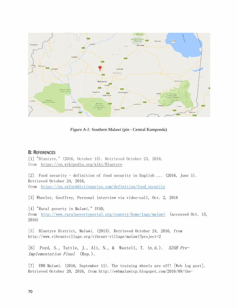
70
Figure A-1: Southern Malawi (pin - Central Kumponda)
B: REFERENCES [1] "Blantyre," (2016, October 15). Retrieved October 23, 2016,
from https://en.wikipedia.org/wiki/Blantyre
[2] Food security - definition of food security in English ... (2016, June 1).
Retrieved October 24, 2016,
from https://en.oxforddictionaries.com/definition/food_security
[3] Wheeler, Geoffrey, Personal interview via video-call, Oct. 2, 2016
[4] "Rural poverty in Malawi," IFAD,
from http://www.ruralpovertyportal.org/country/home/tags/malawi (accessed Oct. 15,
2016)
[5] Blantyre District, Malawi. (2013). Retrieved October 24, 2016, from
http://www.vibrantvillage.org/vibrant-village/malawi?project=2
[6] Poyd, S., Tuttle, J., Ali, N., & Wastell, T. (n.d.). 525B Pre-Implementation Final (Rep.).
[7] EWB Malawi. (2016, September 11). The training wheels are off! [Web log post].
Retrieved October 20, 2016, from http://ewbmalawicp.blogspot.com/2016/09/the-

71
training-wheels-are-off.html
[8] "Bicycle Kit for Model No.99," Bitterroot Tool& Machine, Inc., Grain Maker
Webpage, from http://grainmaker.com/products/bicycle-kit-for-model-no-99/ (accessed
Oct. 10, 2016)
[9] Denison, Cory, "Human powered device with removable flywheel power unit," Patent
# US6983948B2, Webpage,
from https://patents.google.com/patent/US6983948B2/en?q=human+powered&q=flour+mill
(accessed Oct. 21, 2016)
[10] "Fluid2 Indoor Trainer," CycleOps Webpage
from https://www.cycleops.com/product/fluid2 (accessed Oct. 12, 2016)
[11] Henk, "Make a Pedal Powered Grain Mill," Posted - Aug. 5 2012, Provident
Living, New Zealand Webpage, from http://www.providentliving.org.nz/make-a-pedal-
powered-grain-mill/# (accessed Oct. 17, 2016)
[12] Walker, Fergus, "People Powered Flour Mill," Walkerdesignermaker You Tube web
page, from https://www.youtube.com/watch?v=nvwIPX6cH9U#t=172 (accessed Oct. 22,
2016)
[13] "Country Living Grain Mill hooked to 21 speed Bicycle," marthale7 You Tube web
page, from https://www.youtube.com/watch?v=tNDoV6mJ9bQ (accessed Oct. 22, 2016)
[14] Godfrey, H. (2010). Pedal Powered Mill/Degrainer. Retrieved October 24, 2016,
from http://www.mayapedal.org/Mill.pdf
[15] Coggan, A., Dr. (2008, October 10). Power Profiling | TrainingPeaks. Retrieved
October 25, 2016, from http://home.trainingpeaks.com/blog/article/power-profiling
[16] Parsons, D., Roberts, C., Steele, E. W., & Discavage, J., P.E.
Motion Sytem Design (2005, February 1). Belt and chain drives. Retrieved November
12, 2016, from http://machinedesign.com/archive/belt-and-chain-drives
[17] Pedal powered water pumps, threshers, blenders, tile makers and more. (2012,
Summer). Retrieved November 17, 2016,
from http://mayapedal.org/machines.en
[18] Budynas, R. , Nisbett, J. , & Shigley, J. (2008). Shigley's Mechanical Engineering Design. Boston: McGraw-Hill.
[19] Bando USA (n.d.). V-Belt Design Manual. Retrieved January 4, 2017,
from http://www.bandousa.com/html/pdfs/bu-143manual.pdf

72
[20] Francis, R. (2016, March 1). Pushing belt drive efficiency. Retrieved February
05, 2017, from http://machinedesign.com/technologies/pushing-belt-drive-efficiency

73
C: POWER OUTPUT TABLE
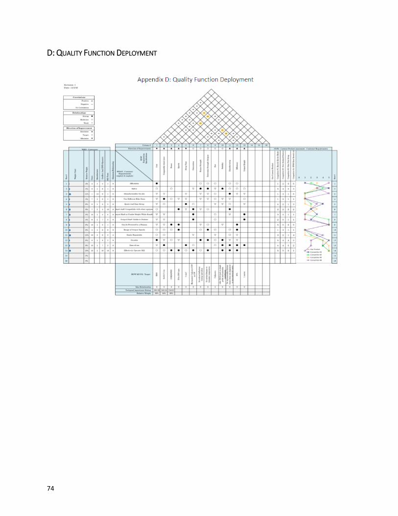
74
D: QUALITY FUNCTION DEPLOYMENT
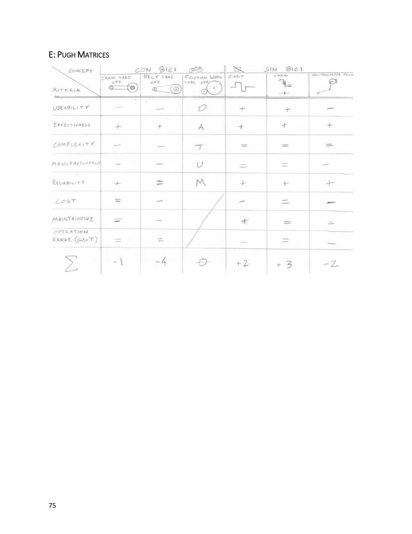
75
E: PUGH MATRICES

76

77

78
F. GANTT CHART

79
G. FAILURE MODES EFFECTS AND ANALYSIS
H. PRELIMINARY DESIGN 4.5.1' – Preliminary Design Concept
With our final system concept selected, we then generated a preliminary design that conveys the basic
layout of the components and how they interface with each other. It is important to note that this
preliminary design is no representation of the final structure or implementation that will result from the
rest of our design process throughout the project. The main goal of this preliminary design is to describe
the fundamental form of the device and the method of power transmission from the user’s pedal power to
the output shaft that supplies power to an attached device such as the maize mill.
Before discussing the features of the current basic design, we should bring a few considerations to
attention that are currently not present but will be implemented during the next phase of the design
process. One major function that is absent in the current design is the interface between the output shaft
and the powered-device. This will be a large area of focus in the detailed design phase, and will be
designed in a manner that ensures compatibility with the maize mill and other devices in the
future. Another large design consideration that is not currently represented is the safety and comfort of
the user. We plan to implement safety features that will prevent the user or bystanders from harming
themselves while the device is in user. The ergonomics of the device will also be improved with an area
in front of the user that allows him to rest his arms on the structure of the device like a form of bicycle
handlebars or a flat, desk-like surface.
Now we will discuss the functions that are currently implemented on the preliminary design. Please refer
to Figure 4.5.1 as the components of the system are discussed. A base frame provides the overall structure
for the device as well as mounting points for each of the components. The user sits on a seat that is
supported by the frame and pedals the crank assembly in an identical manner that a bicycle is pedaled.
From the sprocket of the crank assembly, a chain extends to a cog (or cogs with a derailleur for shifting)
on the intermediate shaft. The intermediate shaft will also contain a flywheel of some form which must be
able to disengage from the cogs so that the user can stop pedaling and the device maintains motion. A belt

80
will then connect from a pulley on the intermediate shaft to a pulley (or system of a pulleys for
torque/speed variation) on the output shaft. Also in the belt system is an adjustable tensioning pulley that
will be able to adjust the belt tension as the belt stretches. This adjustable tensioning pulley also has
potential to enable different gear ratios to be used. The output shaft will be supported by bearings or
bushings so as to minimize energy losses on the output shaft. Also note that the output shaft is
intentionally placed on top of the frame so that the attached powered-device can be operated at standing
height.
Figure 4.5.1. Solid model and component description of the preliminary design concept.
4.5.2' – Materials and Manufacturing
Frame – The frame will most likely be constructed out of a readily available, relatively cheap metal. The
proprietary method of construction will be cutting and welding members together, but there is a potential
to have some portions of the frame bolted together for easier maintenance and repair.
Seat/Seatpost – The seat and seat post will be taken off of a bicycle so that pedaling is natural and close to
the conception that the user has of pedaling a bicycle. The seatpost will have the capability to be raised
and lowered to accommodate for different user heights.
Crank Assembly – The crank assembly will consist of cranks, a crank spindle, bottom bracket, and pedals.
This assembly will be integrated into the frame in a similar fashion to a bicycle. Another potential option
is to cut the bottom bracket housing and seat tube out of an existing bicycle frame to reduce costs and
manufacturing time. A bicycle chain will connect the sprocket of the crank assembly to the intermediate
shaft.
Intermediate Shaft /Flywheel – At this time, we are intending to use a bicycle wheel as the basis for both
the intermediate shaft and the flywheel. In doing so, the cogs (and freewheel) are already in place, which
would remove a significant portion of the manufacturing needed. This also allows for the potential
implementation of a cassette/derailleur combination for one system of torque/speed control. Concrete is
an option to add mass to the bicycle flywheel as benchmarked in Section 2.5.9. Opposite of the chain-
drive side, a pulley will be attached to the intermediate shaft which is connected to the output shaft via a
belt.
Adjustable Belt System – The belt system that connects the intermediate shaft to the output shaft will be
adjustable via a tensioning pulley. The specific belt type and material will be determined in the detailed
design phase.
Output Shaft/Pulley – The output shaft will likely be made of steel to deal with the alternating loads
experienced during use of the system. On the shaft will be the output pulley that is attached by press-fit or
other methods. This pulley may be machined from metal or plastic, or possibly derived from a previous
product such as a wheelbarrow hub or wire spool.
Bearings/Bushings – Bearings that can be purchased in Blantyre are desired for greater efficiency.
However, if bearings are found to be too expensive or otherwise illogical to incorporate, bushings and
other forms of load bearing can be explored.
4.5.3' – Validation with Basic Calculations
Assuming an input power of 150 W at a speed of 90 rpm:
• Input Torque = 16 Nm
o OK - Well below max torque of 250 Nm
• Approximate Shaft Whirl Critical speed (flywheel) = 1750 rpm
o First reduction must avoid spinning flywheel near this speed
• Achievable Speed out = 450 rpm
(see appendix G for calculations)
4.5.4' – Preliminary Cost Analysis
Prototype Cost:
Chain – 2000 MWK (Malawian Kwacha) = $ 2.81

81
Crank – 3000 MWK = $ 4.21
Spindle – 1000 MWK = $ 1.40
Rear derailleur – MWK 3000 = $ 4.21
Concrete (80 lb) {Cost estimate US} = $ 8.00
4-L V Belt (25in) {Cost estimate US} = $ 6.15
Bearings (10mm) {Cost estimate US} $ 24.88 X2 = $ 49.76
Steel Shaft (10mm diameter x 400mm) = $ 8.02
Frame (30ft of 3/4in steel tube) {Cost estimate in US}= $ 66.40
Steel Angle Iron (.5' x .5" x 3ft) {Cost estimate US} $ 6.94 X 2 = $ 13.88
Adjustable-Speed V Belt Pulleys (1.5, 2, 2.5in) {Cost estimate US} $ 13.35 X2 = $ 26.70
TOTAL MATERIAL COST: $ 188.73
Malawi Implementation Cost:
No in-depth cost analysis has been performed for an implementation in Malawi. However, an initial cost
estimate of individual bike parts from a local Malawian Brian Banda indicates that material costs are
much cheaper in Malawi than in the United States. With this in mind, we expect that our team should be
able to meet the target product cost of $100.
4.5.4' -- Preliminary Design Safety Hazard Identification Checklist
To begin this section, we must state the system we plan to create is not a consumer item but rather a piece
of farm/food processing equipment and will therefore will not be confined by strict safety criteria. Having
said that, safety is still a concern of ours. The potential hazards the we can identify in our preliminary
design are:
• Rotating components
o Sprockets
o Chains
o Shafts
• Pinch points at belt pulley interface
• Overheating
Long hair and or lose clothing present the biggest conceivable safety concerns regarding our preliminary
design. Additionally, we expect our system to be used indoors in potentially hot (for humans)
temperatures. It will be important to make the device easy to operate so that the users do not exert
themselves fully and overheat.
A couple safety modifications that are possible include enclosing the frame with plywood or another
material so that the inner components are not as easily accessible during use. This would effectively
remove the dangers of the rotating components inside the frame. We also plan to implement a chain guard
around the pedals' sprocket so that loose clothing will not get caught in between the chain and sprocket.
4.6 – Modification After performing a brief cost analysis of our original preliminary design we concluded that, with
a budget of $100 our design was a bit of a stretch. Furthermore; we do not think all of the
requirements put forth in this project are attainable with the given budget. Moving forward we
plan to modify our system to address the most pressing needs determined.
I. ANALYSIS List of Calculations
1. Tipping
2. Tabulated Power Rating Extrapolation
3. Pulley Calculations

82
o Center Spacing
o Allowable Power
4. Belt Tension
5. Shaft Sizing
6. Rail Friction
7. Spread Sheet

83
ENGINEERING DATA SHEET Sheet No. I-2 Date
Appendix I: Extrapolation Prepared CF 1/25/17
Checked
Approved
Figure I.1 – Represents the row corresponding to 2.6 inch tabulated power ratings
for A-section belts. Although the distribution appears parabolic there is not nearly
enough data to conclude upon a second order fit. For our belt calculations we used a
linear extrapolation of the data (from the 1000 and 2000 [ft/sec] ratings).

84

85

86
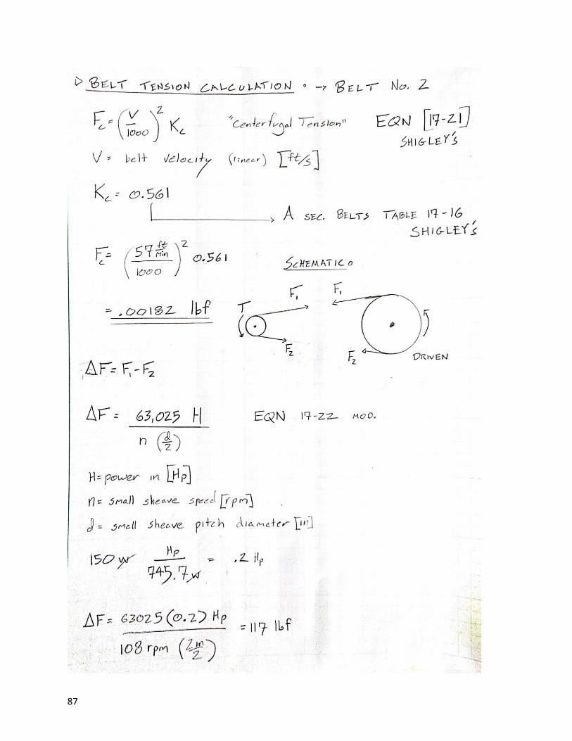
87

88
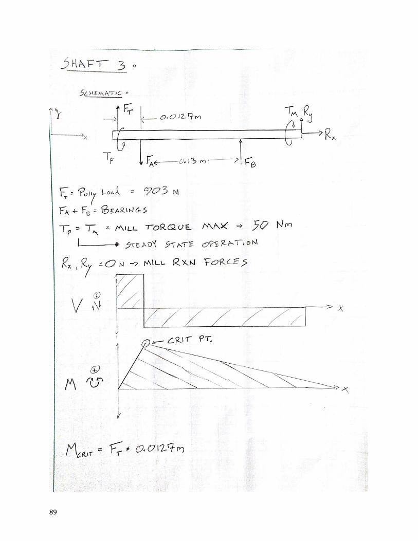
89

90

91
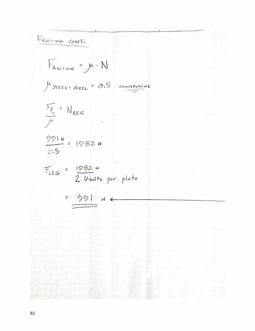
92

93

94

95
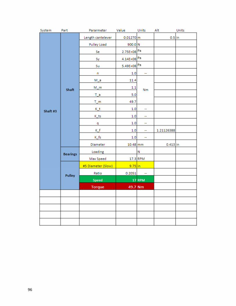
96

97

98
J. PART SPECIFICATION SHEET
Figure J-1 – Specification sheet for steel mounted ball bearings
Figure J-2 – Specification sheet for Square U-bolts
K. TECHNICAL DRAWINGS
List:
1. Top Level Assembly
2. Frame Weldment
3. Individual Tubes
4. Friction Drive Sub-Assembly
5. Friction Drive Swing Arm
6. Friction Drive Base
7. Friction Drive Arm Pivot
8. Axle Support Sub-Assembly
9. Axle Support Sliding Block
10. Axle Clamp Blocks
11. Adjustable Shaft Sub-Assembly
12. Mounting Plate
13. Mounting Plate - Output

99

100
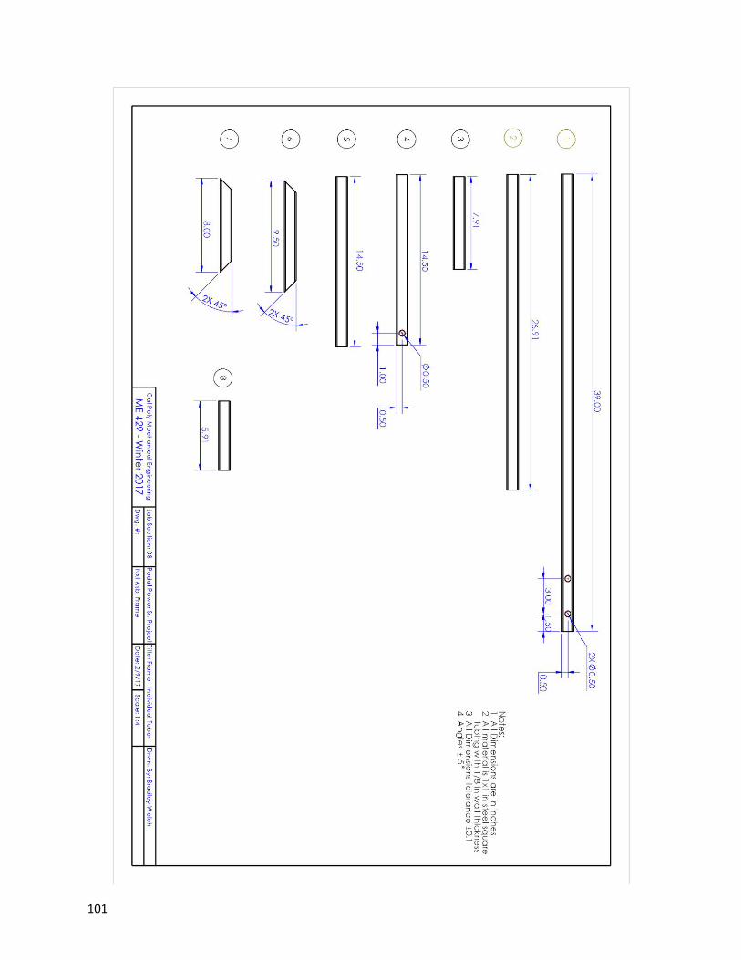
101

102

103

104

105

106

107

108

109

110

111

112
L. SAFETY HAZARD CHECKLIST AND RECOMMENDED ACTIONS

113
Number Hazard Corrective Actions
1 Hair/Clothing/Digit gets caught
between friction drive components
Place the friction drive in a place that is hard to
come into contact unintentionally
2 Hair/Clothing gets caught in belt(s)
Design drivetrain such that the moving
components are as far from user as possible and
covered adequately
3 User overheats pedaling
Design gearing ratios such that the torque
required from user is minimized while
maintaining grinding at a rate of at least 4 [kg/hr].
Also, warn of potential hazard in instructions.
4 Bike falls out of device with user
on it
Design robust axle clamp screws. Possibly add a
fail-safe feature to stop the bike from falling
should the axle clamp fail.
5
Drivetrain failure results in torque
loss at the pedals which can harm
the user if he hits part of the bike or
falls off
Design robust (high safety factor) drivetrain to
avoid failure
6 System tips over when user sits on
bike Design base for adequate stability

114
M. DESIGN VERIFICATION PLAN (DVP&R)
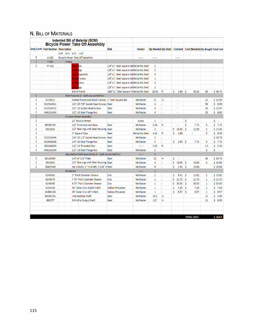
115
N. BILL OF MATERIALS

116
O. BILL OF MATERIALS RECOMMENDED FOR MALAWI BUILD

117
P. OPERATOR'S MANUAL
Operator's Manual: Bicycle Power
Transmission Device
Before proceeding with the setup or use of this device, please be aware of the following
safety concerns:
• Check that loose clothes and or hair has been secured and is not near moving
parts
• Check that bicycle is securely mounted to frame before mounting
• Maintain intended bicycle seating position while operating to ensure stability
• Be wary of heavily loading the pedals, in the case of a catastrophic failure in the
drive train, injury is possible
DEVICE SET UP:
1) Inspect Device for Wear or Broken Parts:
Check for:
• Cracks, stretching, or tears in belts.
• Loose fasteners.
• Cracks or permanent bends in structural components
• Corrosion
• Debris in bearings

118
2) Insert Bicycle into Device's Axle Support Clamps
2a) Remove the upper Axle Clamp Block by loosening the top screws (2).
2b) Place the bicycle's rear axle nuts in the lower block of the Axle Clamp. Make
sure the bike's rear tire is centered above the friction wheel.
2c) Loosen the two sliding base screws and adjust the axle clamps laterally so
that the bicycle's rear axle is well supported. Tighten the screws in the sliding base.
2d) Place the upper Axle Clamp Block over the bicycle's rear axle nuts, and
replace and tighten the two screws so that the bicycle is now secured in all directions.
2e) Lift the front wheel of the bike and place a riser under the front wheel so that
the bike is level.
3) Adjust Friction Wheel to Bicycle's Rear Tire:

119
3a) Rotate the nuts on the underside of the swingarm so that the swingarm
raises the friction wheel until the friction wheel presses sufficiently against the
bicycle's rear tire.
4) Adjust Belt Tension in First Belt
4a) Loosen the four nuts securing the shaft assembly plate to the frame.
4b) Slide the assembly back towards the rear of the device, pre-tensioning the
first belt to approximately 10 lbf.
Note- A board or shovel handle maybe used as a lever to make this
portion easier
4c) Tighten down the U-bolts to securely clamp the plate to the frame rails
4d) Ensure the bottom plate of the assembly is square with the frame and adjust
if necessary
Note- This can likely be performed by visual inspection but a block or
speed square could be used to check
5) Adjust Belt Tension in Second Belt
• Repeat steps 4a-4d for the second reduction.
6) Connect Powered Device (ie Maize Mill) to Output Shaft
IMPORTANT
6a) Mate the mill with the output shaft
6b) By hand, spin the output shaft and observe the mill

120
6c) If it wanders from side to side noticeably there is likely an issue that should
be investigated prior to use
6d) If mill auger and output shaft seem reasonably aligned, tighten fixture
clamping mill to plate
DEVICE USE:
1) Begin pedaling
2) Increase cadence to desirable speed
3) Introduce maize to hopper
IMPORTANT- Do not stop pedaling until there is no maize remaining in the mill
Doing so will result in the potential for binding
4) Continue pedaling