PEAD-RP71, 100, 125, 140JAA - Mitsubishi Electric€¦ · INSTALLATION MANUAL For safe and correct...
28
INSTALLATION MANUAL For safe and correct use, please read this installation manual thoroughly before installing the air-conditioner unit. Air-Conditioners PEAD-RP71, 100, 125, 140JAA English FOR INSTALLER
Transcript of PEAD-RP71, 100, 125, 140JAA - Mitsubishi Electric€¦ · INSTALLATION MANUAL For safe and correct...
INSTALLATION MANUALFor safe and correct use, please read this installation manual thoroughly before installing the air-conditioner unit.
Air-Conditioners
PEAD-RP71, 100, 125, 140JAA
EnglishFOR INSTALLER
KD79D905H01_Cover.fm Page 1 Friday, October 14, 2011 10:08 AM

2
3
[Fig. 3-1]
4[Fig. 4-1]
C
D
C
E
D
A Unit body
B Lifting machine
5[Fig. 5-1] [Fig. 5-2] [Fig. 5-3]
A Center of gravity
A Indoor unit’s bottom surface
5.25.1
A Access door
B Electrical parts box
C Air inlet
D Air outlet
E Ceiling surface
F Service space (viewed from the side)
G Service space (viewed from the direction of arrow)
1 600 mm or more
2 100 mm or more
3 10 mm or more
4 300 mm or more
YX
LW
A
Z
C Nuts (field supply)
D Washers (accessory)
E M10 hanging bolt (field supply)
BC
D
AF
G
3
4
E
A
50~150 450
450
5764
3
777
30
98
23CBA
D
B
E
250
12
B
A
ModelPEAD-RP71PEAD-RP100, 125PEAD-RP140
A110014001600
B115414541654
C120015001700
D106013601560
E120015001700
(mm)
4.1
3.1
A
00b_KB79U749H01_Illust.p65 2011.10.26, 4:52 PM2
3
6
øB
øAa
b
[Fig. 6-1]
a Indoor unit
b Outdoor unit
ad
cb
e f90°
d
c
ba
b
a
a
b
e
bc
dc
A
c
ba
d e f g h
i
[Fig. 6-9]
A Pipe cover (small) (accessory)
B Caution:
Pull out the thermal insulation on the refrigerant piping at thesite, insert the flare nut to flare the end, and replace the insu-lation in its original position.
Take care to ensure that condensation does not form on ex-posed copper piping.
C Liquid end of refrigerant piping
D Gas end of refrigerant piping
E Site refrigerant piping
F Main body
G Pipe cover (large) (accessory)
H Thermal insulation (field supply)
I Pull
J Flare nut
K Return to original position
A
B
CD
F
G
E
H
H
K L
J
IJ
O
O
N
N
20
20
20
20
[Fig. 6-3]
[Fig. 6-6]
[Fig. 6-4] [Fig. 6-5]
a Flare nut
b Copper tube
a Burr
b Copper tube/pipe
c Spare reamer
d Pipe cutter
[Fig. 6-7]
[Fig. 6-8]
a Flaring tool
b Die
c Copper tube
d Flare nut
e Yoke
a Smooth all aroundb Inside is shining without
any scratches
c Even length all around
d Too much
e Tilted
f Scratch onflared plane
g Cracked
h Uneven
i Bad examples
L Ensure that there is no gap here
M Plate on main body
N Band (accessory)
O Ensure that there is no gap here. Place join upwards.
6.1
6.2
a Copper tubes
b Good
c No good
d Tilted
e Uneven
f Burred
6.3
ModelPEAD-RP71, 100, 125, 140
Aø15.88
Bø9.52
00b_KB79U749H01_Illust.p65 2011.10.26, 4:52 PM3

4
[Fig. 6-10] [Fig. 6-11]
6 6.5
C D
G
FE
B
5 25
A
A Indoor unit
B Tie band (accessory)
C Band fixing part
D Insertion margin
E Drain socket (accessory)
F Drain pipe (O.D. ø32 PVC TUBE, field supply)
G Insulating material (field supply)
AB 1
C C C
D 2
E
A Downward slope 1/100 or more
B Connection dia. R1 external thread
C Indoor unit
D Collective piping
E Maximize this length to approx. 10 cm
00b_KB79U749H01_Illust.p65 2011.10.26, 4:52 PM4

5
8
[Fig. 8-1]
8.1
7 7.1
A Outdoor unit power supply
B Earth leakage breaker
C Wiring circuit breaker or isolating switch
D Outdoor unit
E Indoor unit/outdoor unit connecting cords
F Remote controller (option)
G Indoor unit
S1
S2
LN
12
S1
S2
S3S3
A B C
D
EF
G
A Outdoor unit power supply
B Earth leakage breaker
C Wiring circuit breaker or isolating switch
D Outdoor unit
E Indoor unit/outdoor unit connecting cords
F Remote controller (option)
G Indoor unit
S1
S2
LN
12
S1
S2
S3
12
S1
S2
S3S3
12
S1
S2
S3
12
S1
S2
S3
A B C
D
EF
G G G G
A Outdoor unit power supply
B Earth leakage breaker
C Wiring circuit breaker or isolating switch
D Outdoor unit
E Indoor unit/outdoor unit connecting cords
F Remote controller (option)
G Indoor unit
H Option
J Indoor unit power supply
S1S2
LN
12
LN
S1S2S3S3
A CB
D
J
E
B C
F
G
H
A Outdoor unit power supply
B Earth leakage breaker
C Wiring circuit breaker or isolating switch
D Outdoor unit
E Indoor unit/outdoor unit connecting cords
F Remote controller (option)
G Indoor unit
H Option
J Indoor unit power supply
S1S2
LN
12
LN
S1S2S3
12
LN
S1S2S3
12
LN
S1S2S3
12
LN
S1S2S3S3
A B C
D
E
J B C
F
H
G G G G
[Fig. 8-2]
[Fig. 8-3] [Fig. 8-4]
[Fig. 7-1] [Fig. 7-2]
[Fig. 7-3]
[Fig. 7-4]
Duct
Air inlet
Access door
Canvas duct
Ceiling surface
Air outlet
Leave distanceenough to pre-vent short cycle
<A> In case of rear inlet
A
BG
F
A
A
B
C
DE
F
G
D
C E
<B> In case of bottom inlet
A
BG
C E
A
F
D
A
BA Filter
B Bottom plate
C
D
C Nail for the bottom inlet
D Nail for the rear inlet
00b_KB79U749H01_Illust.p65 2011.10.26, 4:52 PM5

6
8.2
F Use PG bushing to keep the weight of the cable and external force from being applied tothe power supply terminal connector. Use a cable tie to secure the cable.
G Power source wiring
H Use ordinary bushing
I Transmission wiring
J Terminal block for power source and indoor transmission
K Terminal block for remote controller
[Fig. 8-2-3] [Fig. 8-2-4]
C Terminal box
D Knockout hole
E Remove
A Screw holding cover (1pc)
B Cover
[Fig. 8-2-1] [Fig. 8-2-2]
8
A
B
C
D
E
H
IF
G
J K
00b_KB79U749H01_Illust.p65 2011.10.26, 4:52 PM6

7
A For installation in the switch box:
B For direct installation on the wall select one of the following:• Prepare a hole through the wall to pass the remote controller cord (in order to run the remote controller cord from
the back), then seal the hole with putty.• Run the remote controller cord through the cut-out upper case, then seal the cut-out notch with putty similarly as
above.
C Wall
D Conduit
E Lock nut
F Bushing
G Switch box
H Remote controller cord
I Seal with putty
J Wood screw
F
A
H
C D
E
GI
I
I
H
B
J
HB-1. B-2.
[Fig. 8-5]
8
A
AB TB6
B
A To the terminal block on the indoor unit
B TB6 (No polarity)
[Fig. 8-6]
8.2
30
46
30
3012
0
83.5
AB
C A Remote controller profile
B Required clearances surrounding the remote controller
C Installation pitch
[Fig. 8-4]
[Fig. 8-3]
A Indoor terminal block
B Earth wire (green/yellow)
C Indoor/outdoor unit connecting wire 3-core 1.5 mm2 or more
D Outdoor terminal block
E Power supply cord : 2.0 mm2 or more
1 Connecting cable
Cable 3-core 1.5 mm2, in conformitywith Design 245 IEC 57.
2 Indoor terminal block
3 Outdoor terminal block
A Indoor terminal block4 Always install an earth wire (1-core 1.5 mm2)
longer than other cables
5 Remote controller cable
Wire No × size (mm2) : Cable 2C × 0.3
This wire accessory of remote controller
(wire length : 10m, non-polar. Max. 500m)
6 Wired remote controller (option)
7 Power supply cord
Cable 3-core 2.0 mm2 or more, in conform-ity with Design 245 IEC 57.
1 2
6
5
2
4
3
7
L N
1 C Indoor/outdoor unitconnecting wire3-core 1.5 mm2 ormore
D Outdoor terminal block
B Earth wire (green/yellow)
E Power supply cord : 2.0 mm2 or more
8.3
00b_KB79U749H01_Illust.p65 2011.10.26, 4:52 PM7

8
A
B
C
D
E
G
H
F
A Signal receiving unit external
B Center of Switch box
C Switch box
D Installation pitch
E 6.5 mm (1/4 inch)
F 70 mm (2 - 3/4 inch)
G 83.5 ± 0.4 mm (3 - 9/32 inch)
H Protrusion (pillar, etc)
[Fig. 8-9]
A
B
C
A Remote controller wire
B Hole (drill a hole on the ceiling to pass the remote controller wire.)
C Signal Receiving Unit
Ceiling cassette type, Ceiling concealed type
[Fig. 8-10]
A B
C
A Fix tightly with tape.
B Remote controller wire
C Order wire
Indoor unit
[Fig. 8-8]
[Fig. 8-11]
H
J
I
When using the switch box When installing directly on the wall
A 150 mm (5 - 15/16 inch)
B Remote controller wire
C Wiring pipe
D Locknut
H Seal around here with putty
I Remote controller wire
J Seal around here with putty
E Bushing
F Switch box
G Seal around here with putty
C
D
B
F
E
G
AWall
8 8.4
IC
OC(00)
CN90
TB1
TB4
1DC
A
B
Standard 1:1
[Fig. 8-7]
A Outdoor unit
B Refrigerant address
C Indoor unit
D Signal receiving unit
Indoor/outdoor wiring
Signal receiving unit wiring
00b_KB79U749H01_Illust.p65 2011.10.26, 4:52 PM8

9
8 8.4
[Fig. 8-12]
[Fig. 8-13]
A B
C D
A Thin-wall portion
B Bottom case
C Remote controller wire
D Conducting wire
[Fig. 8-14]
A
A Screw (M4 x 30)
* When installing the lower case directly on the wall or the ceiling,use wood screws.
Insert the minus screwdriver toward thearrow pointed and wrench it to remove thecover.A flat screwdriver whose width of blade isbetween 4 and 7mm (5/32 - 9/32inch)must be used.
[Fig. 8-15]
11
2
A
1 Hang the cover to the upper hooks (2 places).
2 Mount the cover to the lower case
A Cross-section of upper hooks
00b_KB79U749H01_Illust.p65 2011.10.26, 4:53 PM9
10
8 8.4
[Fig. 8-16]
IC IC IC ICCN90 CN90 CN90 CN90
Pair number: 0
[Fig. 8-17]
ICCN90
ICCN90
Pair number: 0 Pair number: 0
Pair number: 0 Pair number: 0
IC IC IC ICCN90 CN90 CN90 CN90
[Fig. 8-19]
[Fig. 8-18]
Pair number: 0 Pair number: 1 Pair number: 2 Pair number: 3
Pair number: 0 Pair number: 1 Pair number: 2 Pair number: 3
Pair number: 0 Pair number: 0 Pair number: 0 Pair number: 0
A
CN2A
CN3C
SW2
SW1
JP1
JP2
JP3
JP41
JP42
CN22
CN2L
CNXA2
CN32
SWE
CN20
CN90
CN105
CN41
CN4F
CN51
CNXB2
CNXC2
CN44
ON
OFF
<Indoor controller board>
ON/OFF TEMP
FAN
VANE
TEST RUN
AUTO STOP
AUTO START
h
min
LOUVER
MODE
CHECK
RESETSET CLOCK
CHECK
2,4
3
A
[Fig. 8-20]
00b_KB79U749H01_Illust.p65 2011.10.26, 4:53 PM10

11
9
[Fig. 9-1] [Fig. 9-2]
9.2
˚C
˚CSIMPLE
PAR-21MAA
ON/OFF
FILTER
CHECK
OPERATION CLEAR
TEST
TEMP.
MENU
BACK DAYMONITOR/SET
CLOCK
ON/OFF
TEST RUNCOOL, HEAT
A
F
C
E D B
MIHG
˚C
˚CSIMPLE
PAR-21MAA
ON/OFF
FILTER
CHECK
OPERATION CLEAR
TEST
TEMP.
MENU
BACK DAYMONITOR/SET
CLOCK
ON/OFF
B
C
A
E D
A ON/OFF button
B Test run display
C Indoor temperature liquid linetemperature display
D ON/OFF lamp
E Power display
A CHECK button
B Refrigerant address
C TEMP. button
D IC: Indoor unitOC: Outdoor unit
E Check code
F Error code display
Test run remaining time display
G Set temperature button
H Mode selection button
I Fan speed button
M TEST button
8 8.5
[Fig. 8-21]
PAR-21MAA
ON/OFF
FILTER
CHECK
OPERATION CLEAR
TEST
TEMP.
MENU
BACK DAYMONITOR/SET
CLOCK
ON/OFF A
B
DC
G
E
F
4
1
2
1
3 4
1 2
A Filter button (<Enter> button)
B TEST button
C Set Time button
D Timer On/Off button (Set Day button)
E Mode selection button
F Set temperature button
G Timer Menu button (Monitor/Set button)
⁄ Mode number
⁄ Setting number
⁄ Refrigerant address
⁄ Unit number
1
2
3
4
3
1 2
CHECK CHECK
CHECKCHECK
4
ON/OFF TEMP
FAN
VANE
TEST RUN
AUTO STOP
AUTO START
h
min
LOUVER
MODE
CHECK
RESETSET CLOCK
CHECK
E
F
D
C
A
B
A Hour button
B Minute button
C TEMP button
D TEMP button
E ON/OFF button
F CHECK button
[Fig.8-22]
[Fig. 9-3]
A TEST RUN button
B MODE button
C FAN button
D VANE button
9.3
ON/OFF TEMP
FAN
VANE
TEST RUN
AUTO STOP
AUTO START
h
min
LOUVER
MODE
CHECK
RESETSET CLOCK
TEST RUN
B
A
C
D
00b_KB79U749H01_Illust.p65 2011.10.26, 4:53 PM11
12
10
[Fig. 10-1] B
A
G
H
K
L
M
IJ
C
D
E
F
A Indoor unit
B Union
C Liquid pipe
D Gas pipe
E Stop valve
F Outdoor unit
G Refrigerant gas cylinder operating valve
H Refrigerant gas cylinder for R410A withsiphon
I Refrigerant (liquid)
J Electronic scale for refrigerant charging
K Charge hose (for R410A)
L Gauge manifold valve (for R410A)
M Service port
10.1
00b_KB79U749H01_Illust.p65 2011.10.26, 4:53 PM12
13
Contents
1. Safety precautions ................................................................................. 132. Selecting the installation location ........................................................... 133. Selecting an installation site & Accessories ........................................... 144. Fixing hanging bolts ............................................................................... 145. Installing the unit .................................................................................... 14
• Please report to or take consent by the supply authority before connectionto the system.
• Be sure to read “The following should always be observed for safety” beforeinstalling the air conditioner.
• Be sure to observe the cautions specified here as they include importantitems related to safety.
• The indications and meanings are as follows. Warning:
Could lead to death, serious injury, etc.
Caution:Could lead to serious injury in particular environments when operated incor-rectly.• After reading this manual, be sure to keep it together with the instruction
manual in a handy place on the customer’s site.
Symbols put on the unit: Indicates an action that must be avoided.
: Indicates that important instructions must be followed.
: Indicates a part which must be grounded.
: Indicates that caution should be taken with rotating parts.
: Indicates that the main switch must be turned off before servicing.
: Beware of electric shock.
: Beware of hot surface.
Warning:Carefully read the labels affixed to the main unit.
Warning:• Do not use refrigerant other than the type indicated in the manuals provided
with the unit and on the nameplate.- Doing so may cause the unit or pipes to burst, or result in explosion or fire during use, during repair, or at the time of disposal of the unit.- It may also be in violation of applicable laws.- MITSUBISHI ELECTRIC CORPORATION cannot be held responsible for
malfunctions or accidents resulting from the use of the wrong type of refrigerant.• Do not install it by yourself (customer).
Incomplete installation could cause injury due to fire, electric shock, the unitfalling or leakage of water. Consult the dealer from whom you purchased theunit or special installer.
• This appliance is not intended for use by persons (including children) withreduced physical, sensory or mental capabilities, or lack of experience andknowledge, unless they have been given supervision or instruction concern-ing use of the appliance by a person responsible for their safety.
• Install the unit securely in a place which can bear the weight of the unit.When installed in an insufficient strong place, the unit could fall causing injured.
• Use the specified wires to connect the indoor and outdoor units securely andattach the wires firmly to the terminal board connecting sections so the stressof the wires is not applied to the sections.Incomplete connecting and fixing could cause fire.
• Do not use intermediate connection of the power cord or the extension cordand do not connect many devices to one AC outlet.
It could cause a fire or an electric shock due to defective contact, defectiveinsulation, exceeding the permissible current, etc.
• Check that the refrigerant gas does not leak after installation has completed.• Perform the installation securely referring to the installation manual.
Incomplete installation could cause a personal injury due to fire, electric shock,the unit falling or leakage of water.
• Perform electrical work according to the installation manual and be sure touse an exclusive circuit.If the capacity of the power circuit is insufficient or there is incomplete elec-trical work, it could result in a fire or an electric shock.
• If the supply cord is damaged, it must be replaced by the manufacturer, itsservice agent or similarly qualified persons in order to avoid a hazard.
• Attach the electrical part cover to the indoor unit and the service panel to theoutdoor unit securely.If the electrical part cover in the indoor unit and/or the service panel in theoutdoor unit are not attached securely, it could result in a fire or an electricshock due to dust, water, etc.
• Be sure to use the part provided or specified parts for the installation work.The use of defective parts could cause an injury or leakage of water due to afire, an electric shock, the unit falling, etc.
• Ventilate the room if refrigerant leaks during operation.If the refrigerant comes in contact with a flame, poisonous gases will be released.
• Children should be supervised to ensure that they do not play with the appli-ance.
Caution:• Perform grounding.
Do not connect the ground wire to a gas pipe, water pipe arrester or telephoneground wire. Defective grounding could cause an electric shock.
• Do not install the unit in a place where an inflammable gas leaks.If gas leaks and accumulates in the area surrounding the unit, it could causean explosion.
• Install a ground leakage breaker depending on the installation place (where itis humid).If a ground leakage breaker is not installed, it could cause an electric shock.
• Perform the drainage/piping work securely according to the installationmanual.If there is a defect in the drainage/piping work, water could drop from the unitand household goods could be wet and damaged.
• Fasten a flare nut with a torque wrench as specified in this manual.When fastened too tight, a flare nut may broken after a long period and causea leakage of refrigerant.
2. Selecting the installation location
2.1. Indoor unit• Where airflow is not blocked.• Where cool air spreads over the entire room.• Where it is not exposed to direct sunshine.• At a distance 1 m or more away from your TV and radio (to prevent picture from
being distorted or noise from being generated).
• In a place as far away as possible from fluorescent and incandescent lights (so theinfrared remote control can operate the air conditioner normally).
• Where the air filter can be removed and replaced easily.
Warning:Mount the indoor unit into a ceiling strong enough to withstand the weight ofthe unit.
Note: The phrase “Wired remote controller” in this installation manual refers only to the PAR-21MAA. If you need any information for THE PAR-30MAA, please refer toeither the installation manual or initial setting manual which are included in PAR-30MAA box.
6. Refrigerant piping work .......................................................................... 157. Duct work ............................................................................................... 178. Electrical work ........................................................................................ 189. Test run .................................................................................................. 2210. Maintenance .......................................................................................... 24
1. Safety precautions
2.2. Outdoor unit• Where it is not exposed to strong wind.• Where airflow is good and dustless.• Where it is not exposed to rain and direct sunshine.• Where neighbours are not annoyed by operation sound or hot air.• Where rigid wall or support is available to prevent the increase of operation sound
or vibration.• Where there is no risk of combustible gas leakage.• When installing the unit at a high level, be sure to fix the unit legs.• Where it is at least 3 m away from the antenna of TV set or radio. (Otherwise,
images would be disturbed or noise would be generated.)
• Install the unit horizontally.
Caution:Avoid the following places for installation where air conditioner trouble is liableto occur.• Where there is too much machine oil.• Salty environment as seaside areas.• Hot-spring areas.• Where sulfide gas exists.• Other special atmospheric areas.
01_KB79U749H01_GB.p65 2011.10.26, 4:49 PM13

14
3. Selecting an installation site & Accessories
• Select a site with sturdy fixed surface sufficiently durable against the weight of unit.• Before installing unit, the routing to carry in unit to the installation site should be
determined.• Select a site where the unit is not affected by entering air.• Select a site where the flow of supply and return air is not blocked.• Select a site where refrigerant piping can easily be led to the outside.• Select a site which allows the supply air to be distributed fully in room.• Do not install unit at a site with oil splashing or steam in much quantity.• Do not install unit at a site where combustible gas may generate, flow in, stagnate
or leak.• Do not install unit at a site where equipment generating high frequency waves (a
high frequency wave welder for example) is provided.• Do not install unit at a site where fire detector is located at the supply air side. (Fire
detector may operate erroneously due to the heated air supplied during heatingoperation.)
• When special chemical product may scatter around such as site chemical plantsand hospitals, full investigation is required before installing unit. (The plastic com-ponents may be damaged depending on the chemical product applied.)
• If the unit is run for long hours when the air above the ceiling is at high temperature/high humidity (due point above 26 °C), due condensation may be produced in theindoor unit. When operating the units in this condition, add insulation material (10-20 mm) to the entire surface of the indoor unit to avoid due condensation.
3.1. Install the indoor unit on a ceiling strong enoughto sustain its weight
[Fig. 3-1] (P.2)A Access door B Electrical parts box
C Air inlet D Air outlet
E Ceiling surface F Service space (viewed from the side)
G Service space (viewed from the direction of arrow)
1 600 mm or more 2 100 mm or more
3 10 mm or more 4 300 mm or more
* If the optional long-life filter is installed, the dimensions of the air conditionerincrease.
Rear inlet: Depth increases by 30 mm (*1)Bottom inlet: Height increases by 30 mm (*2)
Warning:The unit must be securely installed on a structure that can sustain its weight. Ifthe unit is mounted on an unstable structure, it may fall down causing injuries.
3.2. Securing installation and service space• Select the optimum direction of supply airflow according to the configuration of the
room and the installation position.• As the piping and wiring are connected at the bottom and side surfaces, and the
maintenance is made at the same surfaces, allow a proper space properly. For theefficient suspension work and safety, provide a space as much as possible.
3.3. Indoor unit accessoriesThe unit is provided with the following accessories:
No. Name Quantity1 Pipe cover (for refrigerant piping joint) Small diameter 12 Pipe cover (for refrigerant piping joint) Large diameter 13 Bands for temporary tightening of pipe cover and drain hose 74 Washer 85 Drain socket 1
4. Fixing hanging bolts
5. Installing the unit
5.1. Hanging the unit bodyBring the indoor unit to an installation site as it is packed.To hang the indoor unit, use a lifting machine to lift and pass through thehanging bolts.
[Fig. 5-1] (P.2)A Unit body
B Lifting machine
[Fig. 5-2] (P.2)C Nuts (field supply)
D Washers (accessory)
E M10 hanging bolt (field supply)
5.2. Confirming the unit’s position and fixing hangingbolts
Use the gage supplied with the panel to confirm that the unit body andhanging bolts are positioned in place. If they are not positioned in place, itmay result in dew drops due to wind leak. Be sure to check the positionalrelationship.Use a level to check that the surface indicated by AAAAA is at level. Ensure thatthe hanging bolt nuts are tightened to fix the hanging bolts.To ensure that drain is discharged, be sure to hang the unit at level using alevel.
[Fig. 5-3] (P.2)A Indoor unit’s bottom surface
Caution:Be sure to install the unit body at level.
4.1. Fixing hanging bolts[Fig. 4-1] (P.2)A Center of gravity
(Give site of suspension strong structure.)
Hanging structure• Ceiling: The ceiling structure varies from building to one another. For detailed infor-
mation, consult your construction company.
Center of gravity and Product Weight
Model namePEAD-RP71JAAPEAD-RP100JAAPEAD-RP125JAAPEAD-RP140JAA
W643643643643
L1154145414541654
X325330330332
Y525675675725
Z130130130130
Product Weight (kg)29383943
• If necessary, reinforce the hanging bolts with anti-quake supporting members ascountermeasures against earthquakes.* Use M10 for hanging bolts and anti-quake supporting members (field supply).
1 Reinforcing the ceiling with additional members (edge beam, etc.) must be re-quired to keep the ceiling at level and to prevent the ceiling from vibrations.
2 Cut and remove the ceiling members.
3 Reinforce the ceiling members, and add other members for fixing the ceiling boards.
01_KD79D905H02_GB.p65 2012.2.6, 10:59 AM14
15
6. Refrigerant piping work
[Fig. 6-5] (P.3)a Flare nut
b Copper tube
• Remove flare nuts attached to indoor and outdoor unit, then put them on pipe/tubehaving completed burr removal.(not possible to put them on after flaring work)
6.2.4. Flaring work
[Fig. 6-6] (P.3)a Flaring tool
b Die
c Copper tube
d Flare nut
e Yoke
• Carry out flaring work using flaring tool as shown below.
DimensionPipe diameter A (mm)
(mm) When the tool for R410A is used B (mm)Clutch type
9.52 0 - 0.5 13.215.88 0 - 0.5 19.7
Firmly hold copper tube in a die in the dimension shown in the table at above.
6.2.5. Check
[Fig. 6-7] (P.3)a Smooth all around f Scratch on flared plane
b Inside is shining without any scratches g Cracked
c Even length all around h Uneven
d Too much i Bad examples
e Tilted
• Compare the flared work with a figure in right side hand.• If flare is noted to be defective, cut off the flared section and do flaring work again.
6.3. Pipe connection[Fig. 6-8] (P.3)
• Apply a thin coat of refrigeration oil on the seat surface of pipe.• For connection first align the center, then tighten the first 3 to 4 turns of flare nut.• Use tightening torque table below as a guideline for indoor unit side union joint section,
and tighten using two wrenches. Excessive tightening damages the flare section.
Copper pipe O.D. Flare nut O.D. Tightening torque(mm) (mm) (N·m)ø9.52 22 34 - 42ø15.88 29 68 - 82
Warning:Be careful of flying flare nut! (Internally pressurized)Remove the flare nut as follows:1. Loosen the nut until you hear a hissing noise.2. Do not remove the nut until the gas has been completely released (i.e., hiss-
ing noise stops).3. Check that the gas has been completely released, and then remove the nut.
Outdoor unit connectionConnect pipes to stop valve pipe joint of the outdoor unit in the same manner appliedfor indoor unit.• For tightening use a torque wrench or spanner, and use the same tightening torque
applied for indoor unit.
Refrigerant pipe insulation• After connecting refrigerant piping, insulate the joints (flared joints) with thermal
insulation tubing.
[Fig. 6-9] (P.3)A Pipe cover (small) (accessory)
B Caution:
Pull out the thermal insulation on the refrigerant piping at the site, insert the flare nut to flarethe end, and replace the insulation in its original position.
Take care to ensure that condensation does not form on exposed copper piping.
C Liquid end of refrigerant piping D Gas end of refrigerant piping
E Site refrigerant piping F Main body
G Pipe cover (large) (accessory) H Thermal insulation (field supply)
I Pull J Flare nut
K Return to original position L Ensure that there is no gap here
M Plate on main body N Band (accessory)
O Ensure that there is no gap here. Place join upwards.
Pipe
For liquidFor gas
For liquidFor gas
For liquidFor gas
For liquidFor gas
Outside diameter
mm inch
9.52 3/815.88 5/89.52 3/8
15.88 5/89.52 3/8
15.88 5/89.52 3/8
15.88 5/8
Model
PEAD-RP71PEAD-RP100PEAD-RP125PEAD-RP140
Insulationmaterial
Heat resistingfoam plastic
0.045 specificgravity
Insulationthickness
8 mm8 mm8 mm8 mm8 mm8 mm8 mm8 mm
Min wallthickness
0.8 mm1.0 mm0.8 mm1.0 mm0.8 mm1.0 mm0.8 mm1.0 mm
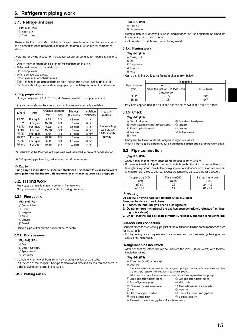
6.1. Refrigerant pipe[Fig. 6-1] (P.3)a Indoor unit
b Outdoor unit
Refer to the Instruction Manual that came with the outdoor unit for the restrictions on the height difference between units and for the amount of additional refrigerant charge.
Avoid the following places for installation where air conditioner trouble is liable tooccur.• Where there is too much oil such as for machine or cooking.• Salty environment as seaside areas.• Hot-spring areas.• Where sulfide gas exists.• Other special atmospheric areas.• This unit has flared connections on both indoor and outdoor sides. [Fig. 6-1]• Insulate both refrigerant and drainage piping completely to prevent condensation.
Piping preparation• Refrigerant pipes of 3, 5, 7, 10 and 15 m are available as optional items.
(1) Table below shows the specifications of pipes commercially available.
(2) Ensure that the 2 refrigerant pipes are well insulated to prevent condensation.
(3) Refrigerant pipe bending radius must be 10 cm or more.
Caution:Using careful insulation of specified thickness. Excessive thickness preventsstorage behind the indoor unit and smaller thickness causes dew drippage.
6.2. Flaring work• Main cause of gas leakage is defect in flaring work.
Carry out correct flaring work in the following procedure.
6.2.1. Pipe cutting
[Fig. 6-3] (P.3)a Copper tubes
b Good
c No good
d Tilted
e Uneven
f Burred
• Using a pipe cutter cut the copper tube correctly.
6.2.2. Burrs removal
[Fig. 6-4] (P.3)a Burr
b Copper tube/pipe
c Spare reamer
d Pipe cutter
• Completely remove all burrs from the cut cross section of pipe/tube.• Put the end of the copper tube/pipe to downward direction as you remove burrs in
order to avoid burrs drop in the tubing.
6.2.3. Putting nut on
+0-0.4
01_KB79U749H01_GB.p65 2011.10.26, 4:49 PM15

16
6. Refrigerant piping work
6.4. Purging procedures leak test
PURGING PROCEDURES
Connect the refrigerant pipes (both the liquid and gas pipes) between the indoorand the outdoor units.
Remove the service port cap of the stop valve on the side of the outdoor unit gas pipe.(The stop valve will not work in its initial state fresh out of the factory (totally closedwith cap on).)
Connect the gage manifold valve and the vacuum pump to the service port of thestop valve on the gas pipe side of the outdoor unit.
Run the vacuum pump. (Vacuumize for more than 15 minutes.)
Check the vacuum with the gage manifold valve, then close the gage manifold valve,and stop the vacuum pump.
Leave it as is for one or two minutes. Make sure the pointer of the gage manifoldvalve remains in the same position. Confirm that the pressure gage show -0.101MPa(-760 mmHg).
Pipe length :7 m maximum
No gas charge is needed.
Pipe length exceeding 7 mCharge the prescribed
amount of gas.
Remove the gage manifold valve quickly from the service port of the stop valve.
After refrigerant pipes are connected and evacuated, fully open all stop valves ongas and liquid pipe sides.Operating without fully opening lowers the performance and causes trouble.
Tighten the cap to the service port to obtain the initial status.
Retighten the cap
Leak test
1.Remove and discard the rubber bung which is inserted in the end of the unit piping.
2.Flare the end of the site refrigerant piping.
3.Pull out the thermal insulation on the site refrigerant piping and replace the insula-tion in its original position.
Cautions On Refrigerant PipingBe sure to use non-oxidative brazing for brazing to ensure that no foreignmatter or moisture enter into the pipe.Be sure to apply refrigerating machine oil over the flare connection seatingsurface and tighten the connection using a double spanner.Provide a metal brace to support the refrigerant pipe so that no load isimparted to the indoor unit end pipe. This metal brace should be provided50 cm away from the indoor unit’s flare connection.
*Close
*Open
Hexagonal wrench
Stop valve
*4 to 5 turns
Stop valve
(or the vacuumpump with thefunction toprevent the backflow)
Gauge manifoldvalve (for R410A)
Pressure gauge (for R410A)
Compound pressuregauge (for R410A)
-0.101MPa(-760 mmHg)
HandleLow
Handle High
Window
Charge hose(for R410A)
Vacuumpump
Adapter forpreventingthe back flow
Charge hose(for R410A)
Service port
Stopvalve
6.5. Drain piping work[Fig. 6-10] (P.4)A Downward slope 1/100 or moreB Connection dia. R1 external threadC Indoor unitD Collective piping
E Maximize this length to approx. 10 cm
• Ensure that the drain piping is downward (pitch of more than 1/100) to the out-door (discharge) side. Do not provide any trap or irregularity on the way. (1)
• Ensure that any cross-wise drain piping is less than 20 m (excluding the differ-ence of elevation). If the drain piping is long, provide metal braces to prevent itfrom waving. Never provide any air vent pipe. Otherwise drain may be ejected.
• Use a hard vinyl chloride pipe O.D. ø32 for drain piping.• Ensure that collected pipes are 10 cm lower than the unit body’s drain port as
shown in 2.• Do not provide any odor trap at the drain discharge port.• Put the end of the drain piping in a position where no odor is generated.• Do not put the end of the drain piping in any drain where ionic gases are generated.
[Fig. 6-11] (P.4)A Indoor unitB Tie band (accessory)C Band fixing partD Insertion marginE Drain socket (accessory)F Drain pipe (O.D. ø32 PVC TUBE, field supply)
G Insulating material (field supply)
1.Insert the drain socket (accessory) into the drain port.(The drain socket must not be bent more than 45° to prevent the socket frombreaking or clogging.)The connecting part between the indoor unit and the drain socket may be dis-connected at the maintenance. Fix the part with the accessory band, not beadhered.
2.Attach the drain pipe (O.D. ø32 PVC TUBE, field supply).(Attach the pipe with glue for the hard vinyl chloride pipe, and fix it with the band(small, accessory).)
3.Perform insulation work on the drain pipe (O.D. ø32 PVC TUBE) and on thesocket (including elbow).
01_KB79U749H01_GB.p65 2011.10.26, 4:49 PM16

17
• Connect canvas duct between unit and duct. [Fig. 7-1] (P.5)• Use incombustible material for duct parts.• Provide full insulation to inlet duct flange and outlet duct to prevent condensation.• Be sure to change the position of air filter to a position where it can be serviced.
<A> In case of rear inlet
<B> In case of bottom inlet
A Duct
B Air inlet
C Access door
D Canvas duct
E Ceiling surface
F Air outlet
G Leave distance enough to prevent short cycle
• Procedure for changing the rear inlet to the bottom inlet. [Fig. 7-2] (P.5)A Filter
B Bottom plate1. Remove air filter. (First remove filter lock screw.)2. Remove the bottom plate.3. Fit the bottom plate to the rear of the body. [Fig. 7-3] (P.5) (Position of lug-holes on the plate are different from those for rear inlet.)
4. Fit filter to the underside of the body. (Be careful of which side of the filter to fit.) [Fig. 7-4] (P.5)
C Nail for the bottom inlet
D Nail for the rear inlet
Caution:• Inlet duct of 850 mm or more should be construted.
To connect the air conditioner main body and the duct for potential equali-zation.
• To reduce the risk of injury from metal sheet edges, wear protective gloves.• To connect the air conditioner main body and the duct for potential equali-
zation.• The noise from the intake will increase dramatically if intake is fitted di-
rectly beneath the main body. Intake should therefore be installed as faraway from the main body as possible.Particular care is required when using it with bottom inlet specifications.
• Install sufficient thermal insulation to prevent condensation forming onoutlet duct flanges and outlet ducts.
• Keep the distance between the inlet grille and the fan over 850 mm.If it is less than 850 mm, install a safety guard not to touch the fan.
• To avoid electrical noise interference, do not run transmission lines at thebottom of the unit.
7. Duct work
When the plate is attached onthe rear side, it exceeds theheight of the rear body panel.
Replicate the plate along the slitwhen there is not enough roomabove for the entire unit.
01_KB79U749H01_GB.p65 2011.10.26, 4:49 PM17
18
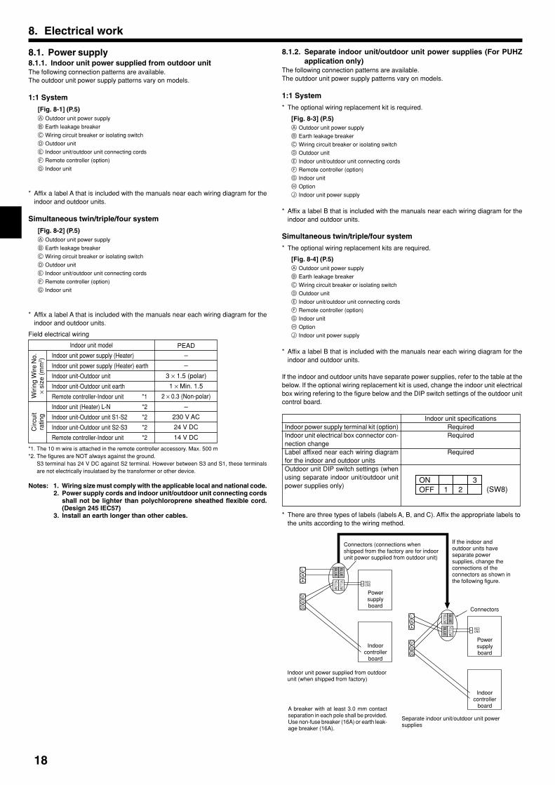
8.1. Power supply8.1.1. Indoor unit power supplied from outdoor unitThe following connection patterns are available.The outdoor unit power supply patterns vary on models.
1:1 System
[Fig. 8-1] (P.5)A Outdoor unit power supply
B Earth leakage breaker
C Wiring circuit breaker or isolating switch
D Outdoor unit
E Indoor unit/outdoor unit connecting cords
F Remote controller (option)
G Indoor unit
* Affix a label A that is included with the manuals near each wiring diagram for theindoor and outdoor units.
Simultaneous twin/triple/four system
[Fig. 8-2] (P.5)A Outdoor unit power supply
B Earth leakage breaker
C Wiring circuit breaker or isolating switch
D Outdoor unit
E Indoor unit/outdoor unit connecting cords
F Remote controller (option)
G Indoor unit
* Affix a label A that is included with the manuals near each wiring diagram for theindoor and outdoor units.
Field electrical wiring
*1. The 10 m wire is attached in the remote controller accessory. Max. 500 m*2. The figures are NOT always against the ground.
S3 terminal has 24 V DC against S2 terminal. However between S3 and S1, these terminalsare not electrically insulataed by the transformer or other device.
Notes: 1. Wiring size must comply with the applicable local and national code.2. Power supply cords and indoor unit/outdoor unit connecting cords
shall not be lighter than polychloroprene sheathed flexible cord.(Design 245 IEC57)
3. Install an earth longer than other cables.
8. Electrical work
8.1.2. Separate indoor unit/outdoor unit power supplies (For PUHZapplication only)
The following connection patterns are available.The outdoor unit power supply patterns vary on models.
1:1 System
* The optional wiring replacement kit is required.
[Fig. 8-3] (P.5)A Outdoor unit power supply
B Earth leakage breaker
C Wiring circuit breaker or isolating switch
D Outdoor unit
E Indoor unit/outdoor unit connecting cords
F Remote controller (option)
G Indoor unit
H Option
J Indoor unit power supply
* Affix a label B that is included with the manuals near each wiring diagram for theindoor and outdoor units.
Simultaneous twin/triple/four system
* The optional wiring replacement kits are required.
[Fig. 8-4] (P.5)A Outdoor unit power supply
B Earth leakage breaker
C Wiring circuit breaker or isolating switch
D Outdoor unit
E Indoor unit/outdoor unit connecting cords
F Remote controller (option)
G Indoor unit
H Option
J Indoor unit power supply
* Affix a label B that is included with the manuals near each wiring diagram for theindoor and outdoor units.
If the indoor and outdoor units have separate power supplies, refer to the table at thebelow. If the optional wiring replacement kit is used, change the indoor unit electricalbox wiring refering to the figure below and the DIP switch settings of the outdoor unitcontrol board.
Indoor power supply terminal kit (option)Indoor unit electrical box connector con-nection changeLabel affixed near each wiring diagramfor the indoor and outdoor unitsOutdoor unit DIP switch settings (whenusing separate indoor unit/outdoor unitpower supplies only)
Indoor unit specificationsRequiredRequired
Required
* There are three types of labels (labels A, B, and C). Affix the appropriate labels tothe units according to the wiring method.
ONOFF 1 2 (SW8)
3
S1
S2
S3
L
N
BLU
E
BLU
E
YELLOW
YELLOW CNDRED
CNDRED
S1
S2
S3
L
N
YELLOW
BLU
E
BLU
E
YELLOW
Connectors (connections whenshipped from the factory are for indoorunit power supplied from outdoor unit)
If the indoor andoutdoor units haveseparate powersupplies, change theconnections of theconnectors as shown inthe following figure.
Connectors
Powersupplyboard
Separate indoor unit/outdoor unit powersupplies
Powersupplyboard
Indoor unit power supplied from outdoorunit (when shipped from factory)
Indoor unit model
Wiri
ng W
ire N
o.×
size
(m
m2 )
Circ
uit
ratin
g
Indoor unit power supply (Heater)
Indoor unit power supply (Heater) earth
Indoor unit-Outdoor unit
Indoor unit-Outdoor unit earth
Remote controller-Indoor unit *1
Indoor unit (Heater) L-N *2
Indoor unit-Outdoor unit S1-S2 *2
Indoor unit-Outdoor unit S2-S3 *2
Remote controller-Indoor unit *2
PEAD
–
–
3 × 1.5 (polar)
1 × Min. 1.5
2 × 0.3 (Non-polar)
–
230 V AC
24 V DC
14 V DC
Indoorcontroller
board
Indoorcontroller
board
A breaker with at least 3.0 mm contactseparation in each pole shall be provided.Use non-fuse breaker (16A) or earth leak-age breaker (16A).
01_KB79U749H01_GB.p65 2011.10.27, 1:19 PM18

19
8. Electrical work
8.2. Indoor wire connectionWork procedure1.Remove 2 screws to detach the electric component cover.2.Route each cable through the wiring intake into the electric component box. (Pro-
cure power cable and in-out connecting cable locally and use remote control cablesupplied with the unit.)
3.Securely connect the power cable and the in-out connecting cable and the remotecontrol cable to the terminal blocks.
4.Secure the cables with clamps inside the electric component box.5.Attach the electric component cover as it was.• Fix power supply cable and indoor/outdoor cable to control box by using buffer
bushing for tensile force. (PG connection or the like.)
Warning:• Attach the electrical part cover securely. If it is attached incorrectly, it could
result in a fire, electric shock due to dust, water, etc.• Use the specified indoor/outdoor unit connecting wire to connect the indoor
and outdoor units and fix the wire to the terminal block securely so that nostress is applied to the connecting section of the terminal block. Incompleteconnection or fixing of the wire could result in a fire.
[Fig. 8-2-1] (P.6)A Screw holding cover (1pc)
B Cover
[Fig. 8-2-2] (P.6)C Terminal box
D Knockout hole
E Remove
[Fig. 8-2-3] (P.6)F Use PG bushing to keep the weight of the cable and external force from being applied to the
power supply terminal connector. Use a cable tie to secure the cable.
G Power source wiring
H Use ordinary bushing
I Transmission wiring
[Fig. 8-2-4] (P.6)J Terminal block for power source and indoor transmission
K Terminal block for remote controller
[Fig. 8-3] (P.7)A Indoor terminal block
B Earth wire (green/yellow)
C Indoor/outdoor unit connecting wire 3-core 1.5 mm2 or more
D Outdoor terminal block
E Power supply cord : 2.0 mm2 or more
1 Connecting cable
Cable 3-core 1.5 mm2, in conformity with Design 245 IEC 57.
2 Indoor terminal block
3 Outdoor terminal block
4 Always install an earth wire (1-core 1.5 mm2) longer than other cables
5 Remote controller cable
Wire No × size (mm2) : Cable 2C × 0.3
This wire accessory of remote controller
(wire length : 10 m, non-polar. Max. 500 m)
6 Wired remote controller (option)
7 Power supply cord
Cable 3-core 2.0 mm2 or more, in conformity with Design 245 IEC 57.
• Perform wiring as shown in [Fig. 8-3] (P.7). (Procure the cable locally.)Make sure to use cables of the correct polarity only.
• Connect the terminal blocks as shown in [Fig. 8-3] (P.7).
Caution:• Use care not to make mis-wiring.• Firmly tighten the terminal screws to prevent them from loosening.• After tightening, pull the wires lightly to confirm that they do not move.
8.3. Remote controller (wired remote controller (option))8.3.1. For wired remote controller1) Installing procedures(1) Select an installing position for the remote controller.The temperature sensors are located on both remote controller and indoor unit.
Procure the following parts locally:Two piece switch boxThin copper conduit tubeLock nuts and bushings
[Fig. 8-4] (P.7)A Remote controller profile
B Required clearances surrounding the remote controller
C Installation pitch
(2) Seal the service entrance for the remote controller cord with putty to prevent pos-sible invasion of dew drops, water, cockroaches or worms.
[Fig. 8-5] (P.7)A For installation in the switch box:
B For direct installation on the wall select one of the following:
• Prepare a hole through the wall to pass the remote controller cord (in order to run the remote
controller cord from the back), then seal the hole with putty.
• Run the remote controller cord through the cut-out upper case, then seal the cut-out notchwith putty similarly as above.
C Wall G Switch box
D Conduit H Remote controller cord
E Lock nut I Seal with putty
F Bushing J Wood screw
B-1. To lead the remote controller cord from the back of the controller:B-2. To run the remote controller cord through the upper portion:(3) For direct installation on the wall
2) Connecting procedures1 Connect the remote controller cord to the terminal block.
[Fig. 8-6] (P.7)A To the terminal block on the indoor unit
B TB6 (No polarity)2 Set the dip switch No.1 shown below when using two remote controller’s for the
same group.3) Function selection of remote controllerIf two remote controllers are connected, set one to “Main” and the other to “Sub”. Forsetting procedures, refer to “Function selection of remote controller” in the operationmanual for the indoor unit.
8.4. Remote controller (wireless remote controller (op-tion))
8.4.1. For wireless remote controller (option)1) Installation area
• Area in which the remote controller is not exposed to direct sunshine.
• Area in which there is no near by heating source.
• Area in which the remote controller is not exposed to cold (or hot) winds.
• Area in which the remote controller can be operated easily.
• Area in which the remote controller is beyond the reach of children.* The signal can travel up to approximately 7 meters (in a streight line) within 45 degrees to
both right and left of the center line of the receiver.
01_KB79U749H01_GB.p65 2011.10.26, 4:49 PM19
20
8. Electrical work
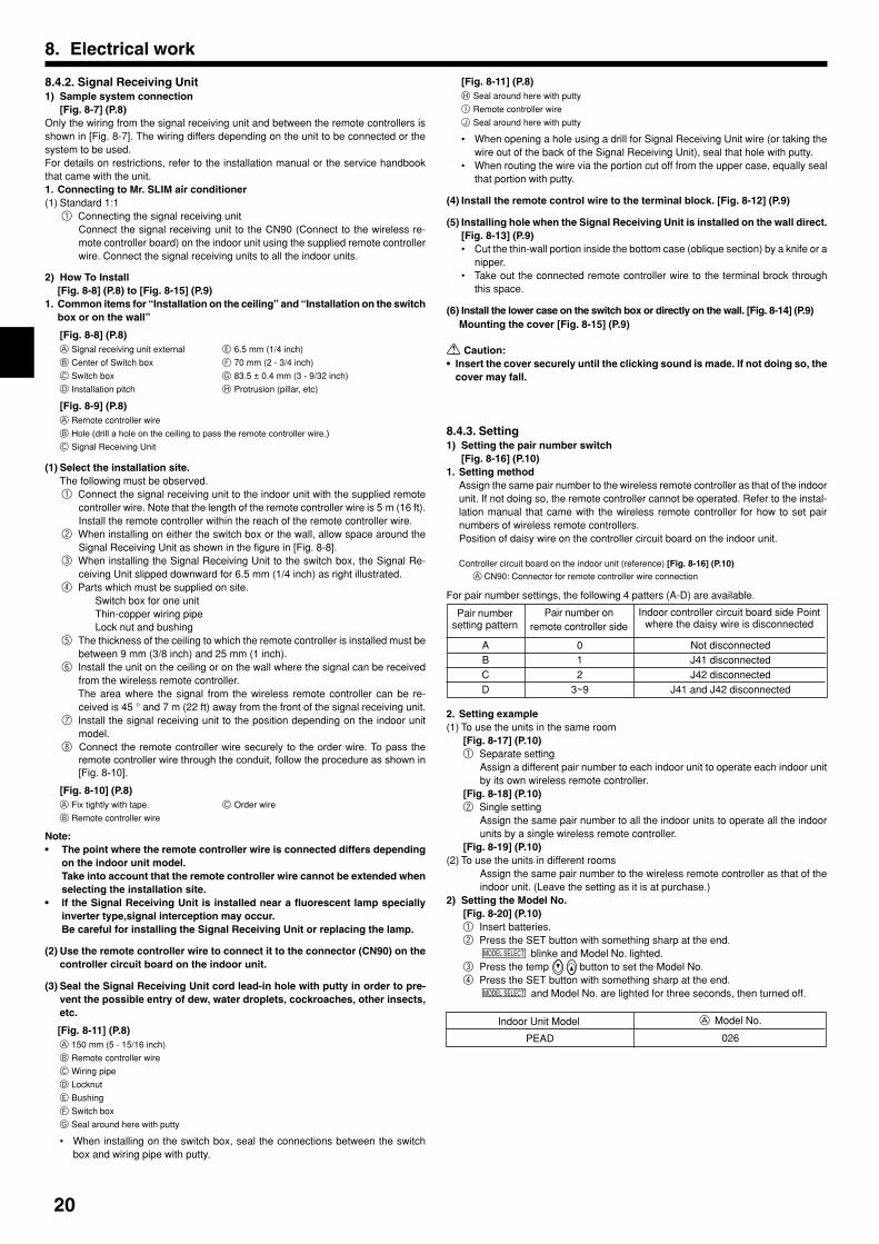
2) How To Install[Fig. 8-8] (P.8) to [Fig. 8-15] (P.9)
1. Common items for “Installation on the ceiling” and “Installation on the switchbox or on the wall”
[Fig. 8-8] (P.8)A Signal receiving unit external E 6.5 mm (1/4 inch)
B Center of Switch box F 70 mm (2 - 3/4 inch)
C Switch box G 83.5 ± 0.4 mm (3 - 9/32 inch)
D Installation pitch H Protrusion (pillar, etc)
[Fig. 8-9] (P.8)A Remote controller wire
B Hole (drill a hole on the ceiling to pass the remote controller wire.)
C Signal Receiving Unit
(1) Select the installation site.The following must be observed.1 Connect the signal receiving unit to the indoor unit with the supplied remote
controller wire. Note that the length of the remote controller wire is 5 m (16 ft).Install the remote controller within the reach of the remote controller wire.
2 When installing on either the switch box or the wall, allow space around theSignal Receiving Unit as shown in the figure in [Fig. 8-8].
3 When installing the Signal Receiving Unit to the switch box, the Signal Re-ceiving Unit slipped downward for 6.5 mm (1/4 inch) as right illustrated.
4 Parts which must be supplied on site.Switch box for one unitThin-copper wiring pipeLock nut and bushing
5 The thickness of the ceiling to which the remote controller is installed must bebetween 9 mm (3/8 inch) and 25 mm (1 inch).
6 Install the unit on the ceiling or on the wall where the signal can be receivedfrom the wireless remote controller.The area where the signal from the wireless remote controller can be re-ceived is 45 ° and 7 m (22 ft) away from the front of the signal receiving unit.
7 Install the signal receiving unit to the position depending on the indoor unitmodel.
8 Connect the remote controller wire securely to the order wire. To pass theremote controller wire through the conduit, follow the procedure as shown in[Fig. 8-10].
[Fig. 8-10] (P.8)A Fix tightly with tape. C Order wire
B Remote controller wire
Note:• The point where the remote controller wire is connected differs depending
on the indoor unit model.Take into account that the remote controller wire cannot be extended whenselecting the installation site.
• lf the Signal Receiving Unit is installed near a fluorescent lamp speciallyinverter type,signal interception may occur.Be careful for installing the Signal Receiving Unit or replacing the lamp.
(2) Use the remote controller wire to connect it to the connector (CN90) on thecontroller circuit board on the indoor unit.
(3) Seal the Signal Receiving Unit cord lead-in hole with putty in order to pre-vent the possible entry of dew, water droplets, cockroaches, other insects,etc.
[Fig. 8-11] (P.8)A 150 mm (5 - 15/16 inch)
B Remote controller wire
C Wiring pipe
D Locknut
E Bushing
F Switch box
G Seal around here with putty
• When installing on the switch box, seal the connections between the switchbox and wiring pipe with putty.
[Fig. 8-11] (P.8)H Seal around here with putty
I Remote controller wire
J Seal around here with putty
• When opening a hole using a drill for Signal Receiving Unit wire (or taking thewire out of the back of the Signal Receiving Unit), seal that hole with putty.
• When routing the wire via the portion cut off from the upper case, equally sealthat portion with putty.
(4) Install the remote control wire to the terminal block. [Fig. 8-12] (P.9)
(5) Installing hole when the Signal Receiving Unit is installed on the wall direct.[Fig. 8-13] (P.9)• Cut the thin-wall portion inside the bottom case (oblique section) by a knife or a
nipper.• Take out the connected remote controller wire to the terminal brock through
this space.
(6) Install the lower case on the switch box or directly on the wall. [Fig. 8-14] (P.9)Mounting the cover [Fig. 8-15] (P.9)
Caution:• Insert the cover securely until the clicking sound is made. If not doing so, the
cover may fall.
8.4.2. Signal Receiving Unit1) Sample system connection
[Fig. 8-7] (P.8)Only the wiring from the signal receiving unit and between the remote controllers isshown in [Fig. 8-7]. The wiring differs depending on the unit to be connected or thesystem to be used.For details on restrictions, refer to the installation manual or the service handbookthat came with the unit.1. Connecting to Mr. SLIM air conditioner(1) Standard 1:1
1 Connecting the signal receiving unitConnect the signal receiving unit to the CN90 (Connect to the wireless re-mote controller board) on the indoor unit using the supplied remote controllerwire. Connect the signal receiving units to all the indoor units.
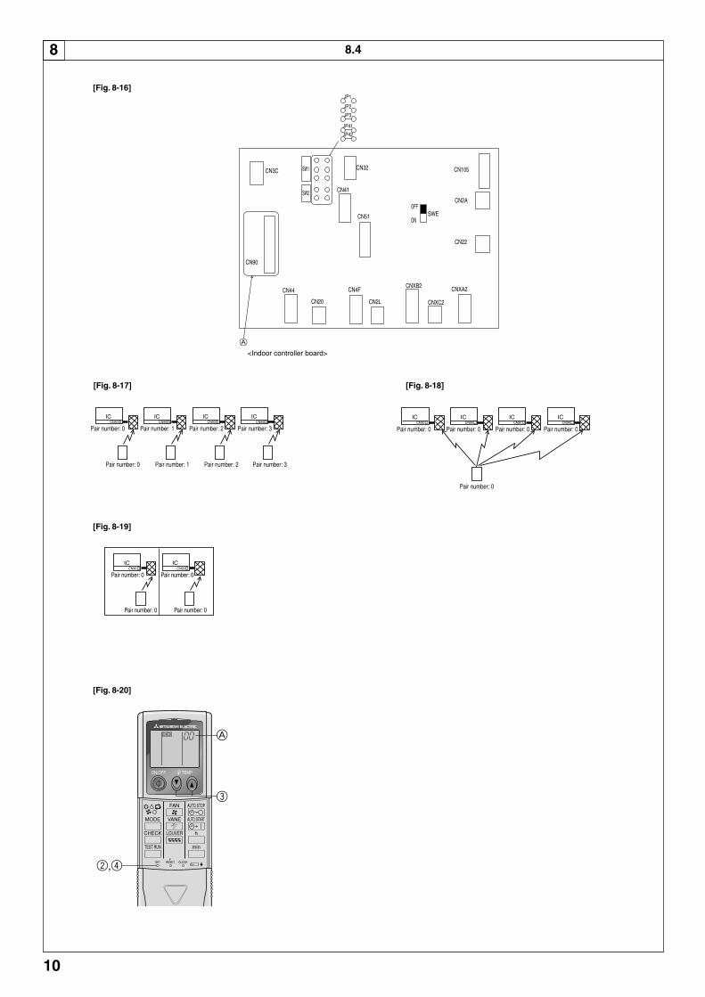
2. Setting example(1) To use the units in the same room
[Fig. 8-17] (P.10)1 Separate setting
Assign a different pair number to each indoor unit to operate each indoor unitby its own wireless remote controller.
[Fig. 8-18] (P.10)2 Single setting
Assign the same pair number to all the indoor units to operate all the indoorunits by a single wireless remote controller.
[Fig. 8-19] (P.10)(2) To use the units in different rooms
Assign the same pair number to the wireless remote controller as that of theindoor unit. (Leave the setting as it is at purchase.)
2) Setting the Model No.[Fig. 8-20] (P.10)1 Insert batteries.2 Press the SET button with something sharp at the end.
MODEL SELECT blinke and Model No. lighted.3 Press the temp button to set the Model No.4 Press the SET button with something sharp at the end.
MODEL SELECT and Model No. are lighted for three seconds, then turned off.
8.4.3. Setting1) Setting the pair number switch
[Fig. 8-16] (P.10)1. Setting method
Assign the same pair number to the wireless remote controller as that of the indoorunit. If not doing so, the remote controller cannot be operated. Refer to the instal-lation manual that came with the wireless remote controller for how to set pairnumbers of wireless remote controllers.Position of daisy wire on the controller circuit board on the indoor unit.
Controller circuit board on the indoor unit (reference) [Fig. 8-16] (P.10)A CN90: Connector for remote controller wire connection
For pair number settings, the following 4 patters (A-D) are available.
Pair numbersetting pattern
Pair number onremote controller side
Indoor controller circuit board side Pointwhere the daisy wire is disconnected
ABCD
012
3~9
Not disconnectedJ41 disconnectedJ42 disconnected
J41 and J42 disconnected
Indoor Unit Model A Model No.
PEAD 026
01_KB79U749H01_GB.p65 2011.10.26, 4:49 PM20
21
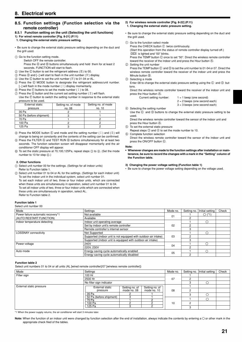
8.5. Function settings (Function selection via theremote controller)
8.5.1 Function setting on the unit (Selecting the unit functions)1) For wired remote controller [Fig. 8-21] (P.11) 1. Changing the external static pressure setting.
• Be sure to change the external static pressure setting depending on the duct andthe grill used.
1 Go to the function setting mode.Switch OFF the remote controller.Press the A and B buttons simultaneously and hold them for at least 2seconds. FUNCTION will start to flash.
2 Use the C button to set the refrigerant address (3) to 00.3 Press D and [--] will start to flash in the unit number (4) display.4 Use the C button to set the unit number (4) to 01-04 or AL.5 Press the E MODE button to designate the refrigerant address/unit number.
[--] will flash in the mode number (1) display momentarily.6 Press the F buttons to set the mode number (1) to 08.7 Press the G button and the current set setting number (2) will flash.
Use the F button to switch the setting number in response to the external staticpressure to be used.
8 Press the MODE button E and mode and the setting number (1) and (2) willchange to being on constantly and the contents of the setting can be confirmed.
9 Press the FILTER A and TEST RUN B buttons simultaneously for at least twoseconds. The function selection screen will disappear momentarily and the airconditioner OFF display will appear.
0 To set the static pressure at 70,100,125Pa, repeat steps 3 to 9. (Set the modenumber to 10 for step 6.)
2. Other functions1 Select unit number 00 for the settings. (Settings for all indoor units)
Refer to Function table 1.2 Select unit number 01 to 04 or AL for the settings. (Settings for each indoor unit)
To set the indoor unit in the individual system, select unit number 01.To set each indoor unit of two, three or four indoor units, which are connectedwhen these units are simultaneously in operation, select unit number 01 to 04.To set all indoor units of two, three or four indoor units which are connected whenthese units are simultaneously in operation, select AL.Refer to Function table 2.
8. Electrical work
Function table 2Select unit numbers 01 to 04 or all units (AL [wired remote controller]/07 [wireless remote controller])
*1 When the power supply returns, the air conditioner will start 3 minutes later.
Note: When the function of an indoor unit were changed by function selection after the end of installation, always indicate the contents by entering a or other mark in theappropriate check filed of the tables.
Function table 1Select unit number 00
SettingsNot availableAvailableIndoor unit operating averageSet by indoor unit’s remote controllerRemote controller’s internal sensorNot SupportedSupported (indoor unit is not equipped with outdoor-air intake)Supported (indoor unit is equipped with outdoor-air intake)240V220V, 230VEnergy saving cycle automatically enabledEnergy saving cycle automatically disabled
Mode no. Setting no. Initial setting Check1 (*1)
0121
02 231
03 231
0421
052
ModePower failure automatic recovery*1(AUTO RESTART FUNCTION)Indoor temperature detecting
LOSSNAY connectivity
Power voltage
Auto mode
External staticpressure
35 Pa50 Pa (before shipment)70 Pa100 Pa125 Pa
Setting no. of modeno. 08
23123
Setting no. of modeno. 10
11222
2) For wireless remote controller [Fig. 8-22] (P.11) 1. Changing the external static pressure setting.
• Be sure to change the external static pressure setting depending on the duct andthe grill used.
1 Go to the function select modePress the CHECK button F twice continuously.(Start this operation from the status of remote controller display turned off.)
CHECK is lighted and “00” blinks.Press the TEMP button C once to set “50”. Direct the wireless remote controllertoward the receiver of the indoor unit and press the Hour button A.
2 Setting the unit numberPress the TEMP button C and D to set the unit number to 01-04 or 07. Direct thewireless remote controller toward the receiver of the indoor unit and press theMinute button B.
3 Selecting a modeEnter 08 to change the external static pressure setting using the C and D but-tons.Direct the wireless remote controller toward the receiver of the indoor unit andpress the Hour button A.
Current setting number: 1 = 1 beep (one second)2 = 2 beeps (one second each)3 = 3 beeps (one second each)
4 Selecting the setting numberUse the C and D buttons to change the external static pressure setting to beused.Direct the wireless remote controller toward the sensor of the indoor unit andpress the Hour button A.
5 To set the external static pressureRepeat steps 3 and 4 to set the mode number to 10.
6 Complete function selectionDirect the wireless remote controller toward the sensor of the indoor unit andpress the ON/OFF button E.
Note:• Whenever changes are made to the function settings after installation or main-
tenance, be sure to record the changes with a mark in the “Setting” column ofthe Function table.
3) Changing the power voltage setting (Function table 1)• Be sure to change the power voltage setting depending on the voltage used.
ModeFilter sign
External static pressure
Settings100 Hr2500 HrNo filter sign indicator
Mode no. Setting no. Initial setting Check1
07 231
08 2
3
1
10 2
3
35 Pa50 Pa (before shipment)70 Pa100 Pa125 Pa
23123
11222
External staticpressure
Setting no. ofmode no. 08
Setting no. ofmode no. 10
01_KD79D905H02_GB.p65 2012.2.6, 10:59 AM21

22
9.1. Before test runAfter completing installation and the wiring and piping of the indoor and outdoorunits, check for refrigerant leakage, looseness in the power supply or controlwiring, wrong polarity, and no disconnection of one phase in the supply.Use a 500-volt megohmmeter to check that the resistance between the powersupply terminals and ground is at least 1.0 MΩΩΩΩΩ.Do not carry out this test on the control wiring (low voltage circuit) termi-nals. Warning:
Do not use the air conditioner if the insulation resistance is less than 1.0 MΩΩΩΩΩ.Insulation resistanceAfter installation or after the power source to the unit has been cut for an extendedperiod, the insulation resistance will drop below 1 MΩ due to refrigerant accumulat-ing in the compressor. This is not a malfunction. Perform the following procedures.1. Remove the wires from the compressor and measure the insulation resistance of
the compressor.2. If the insulation resistance is below 1 MΩ, the compressor is faulty or the resist-
ance dropped due the accumulation of refrigerant in the compressor.3. After connecting the wires to the compressor, the compressor will start to warm
up after power is supplied. After supplying power for the times indicated below,measure the insulation resistance again.• The insulation resistance drops due to accumulation of refrigerant in the com-
pressor. The resistance will rise above 1 MΩ after the compressor is warmedup for two to three hours.(The time necessary to warm up the compressor varies according to atmos-pheric conditions and refrigerant accumulation.)
• To operate the compressor with refrigerant accumulated in the compressor,the compressor must be warmed up at least 12 hours to prevent breakdown.
4. If the insulation resistance rises above 1 MΩ, the compressor is not faulty.
Caution:• The compressor will not operate unless the power supply phase connection
is correct.• Turn on the power at least 12 hours before starting operation.- Starting operation immediately after turning on the main power switch can result in
severe damage to internal parts. Keep the power switch turned on during the op-erational season.
9. Test run
9.2. Test run9.2.1. Using wired remote controller (option)1 Turn on the power at least 12 hours before the test run.2 Press the [TEST] button twice. “TEST RUN” liquid crystal display3 Press the [Mode selection] button. Make sure that wind is blown out.4 Press the [Mode selection] button and switch to the cooling (or heating) mode.
Make sure that cold (or warm) wind is blown out.5 Press the [Fan speed] button. Make sure that the wind speed is switched.6 Check operation of the outdoor unit fan.7 Release test run by pressing the [ON/OFF] button. Stop8 Register a telephone number.
The telephone number of the repair shop, sales office, etc., to contact if an erroroccurs can be registered in the remote controller. The telephone number will bedisplayed when an error occurs. For registration procedures, refer to the operationmanual for the indoor unit.
[Fig. 9-1] (P.11)A ON/OFF button
B Test run display
C Indoor temperature liquid line temperature display
D ON/OFF lamp
E Power display
F Error code display
Test run remaining time display
G Set temperature button
H Mode selection button
I Fan speed button
M TEST button
9.2.2. Wired remote controller1 Turn on the power.2 Press the [CHECK] button twice.3 Set refrigerant address with [TEMP] button if system control is used.4 Press the [ON/OFF] button to stop the self-check.
[Fig. 9-2] (P.11)A CHECK button
B Refrigerant address
C TEMP. button
D IC: Indoor unitOC: Outdoor unit
E Check code
• For description of each check code, refer to the following table.
1 Check code Symptom RemarkP1 Intake sensor errorP2, P9 Pipe (Liquid or 2-phase pipe) sensor errorE6, E7 Indoor/outdoor unit communication errorP4 Drain sensor errorP5 Drain pump errorPA Forced compressor errorP6 Freezing/Overheating safeguard operationEE Communication error between indoor and outdoor unitsP8 Pipe temperature errorE4 Remote controller signal receiving errorFb Indoor unit control system error (memory error, etc.)E0, E3 Remote controller transmission errorE1, E2 Remote controller control board errorE9 Indoor/outdoor unit communication error (Transmitting error) (Outdoor unit)UP Compressor overcurrent interruptionU3, U4 Open/short of outdoor unit thermistorsUF Compressor overcurrent interruption (When compressor locked)U2 Abnormal high discharging temperature/49C worked/insufficient refrigerantU1, Ud Abnormal high pressure (63H worked)/Overheating safeguard operationU5 Abnormal temperature of heat sinkU8 Outdoor unit fan safeguard stopU6 Compressor overcurrent interruption/Abnormal of power moduleU7 Abnormality of super heat due to low discharge temperatureU9, UH Abnormality such as overvoltage or voltage shortage and abnormal synchronous signal to main circuit/
Current sensor errorOthers Other errors (Refer to the technical manual for the outdoor unit.)
• On wired remote controller1 Check code displayed in the LCD.
For details, check the LED displayof the outdoor controller board.
01_KB79U749H01_GB.p65 2011.10.26, 4:49 PM22
23
9. Test run
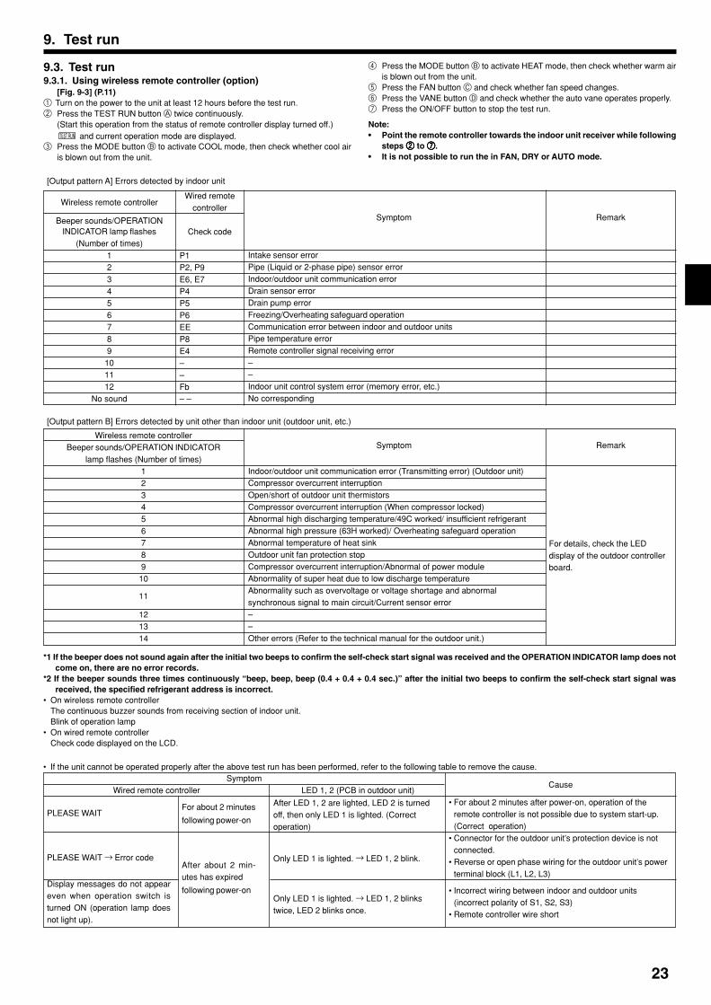
• If the unit cannot be operated properly after the above test run has been performed, refer to the following table to remove the cause.
PLEASE WAIT
PLEASE WAIT → Error code
Display messages do not appeareven when operation switch isturned ON (operation lamp doesnot light up).
Symptom
After LED 1, 2 are lighted, LED 2 is turnedoff, then only LED 1 is lighted. (Correctoperation)
Only LED 1 is lighted. → LED 1, 2 blink.
Only LED 1 is lighted. → LED 1, 2 blinkstwice, LED 2 blinks once.
• For about 2 minutes after power-on, operation of theremote controller is not possible due to system start-up.(Correct operation)
• Connector for the outdoor unit’s protection device is notconnected.
• Reverse or open phase wiring for the outdoor unit’s powerterminal block (L1, L2, L3)
• Incorrect wiring between indoor and outdoor units(incorrect polarity of S1, S2, S3)
• Remote controller wire short
For about 2 minutes
following power-on
After about 2 min-utes has expired
following power-on
LED 1, 2 (PCB in outdoor unit)Wired remote controllerCause
[Output pattern B] Errors detected by unit other than indoor unit (outdoor unit, etc.)
Wireless remote controllerBeeper sounds/OPERATION INDICATOR
lamp flashes (Number of times)12345678910
11
121314
Symptom
Indoor/outdoor unit communication error (Transmitting error) (Outdoor unit)Compressor overcurrent interruptionOpen/short of outdoor unit thermistorsCompressor overcurrent interruption (When compressor locked)Abnormal high discharging temperature/49C worked/ insufficient refrigerantAbnormal high pressure (63H worked)/ Overheating safeguard operationAbnormal temperature of heat sinkOutdoor unit fan protection stopCompressor overcurrent interruption/Abnormal of power moduleAbnormality of super heat due to low discharge temperatureAbnormality such as overvoltage or voltage shortage and abnormalsynchronous signal to main circuit/Current sensor error––Other errors (Refer to the technical manual for the outdoor unit.)
Remark
For details, check the LEDdisplay of the outdoor controllerboard.
[Output pattern A] Errors detected by indoor unit
Wireless remote controller
Beeper sounds/OPERATIONINDICATOR lamp flashes
(Number of times)123456789
101112
No sound
Wired remotecontroller
Check code
P1P2, P9E6, E7P4P5P6EEP8E4––Fb– –
Symptom
Intake sensor errorPipe (Liquid or 2-phase pipe) sensor errorIndoor/outdoor unit communication errorDrain sensor errorDrain pump errorFreezing/Overheating safeguard operationCommunication error between indoor and outdoor unitsPipe temperature errorRemote controller signal receiving error––Indoor unit control system error (memory error, etc.)No corresponding
Remark
*1 If the beeper does not sound again after the initial two beeps to confirm the self-check start signal was received and the OPERATION INDICATOR lamp does notcome on, there are no error records.
*2 If the beeper sounds three times continuously “beep, beep, beep (0.4 + 0.4 + 0.4 sec.)” after the initial two beeps to confirm the self-check start signal wasreceived, the specified refrigerant address is incorrect.
• On wireless remote controllerThe continuous buzzer sounds from receiving section of indoor unit.Blink of operation lamp
• On wired remote controllerCheck code displayed on the LCD.
9.3. Test run9.3.1. Using wireless remote controller (option)
[Fig. 9-3] (P.11)1 Turn on the power to the unit at least 12 hours before the test run.2 Press the TEST RUN button A twice continuously.
(Start this operation from the status of remote controller display turned off.)TEST RUN and current operation mode are displayed.
3 Press the MODE button B to activate COOL mode, then check whether cool airis blown out from the unit.
4 Press the MODE button B to activate HEAT mode, then check whether warm airis blown out from the unit.
5 Press the FAN button C and check whether fan speed changes.6 Press the VANE button D and check whether the auto vane operates properly.7 Press the ON/OFF button to stop the test run.
Note:• Point the remote controller towards the indoor unit receiver while following
steps 22222 to 77777.• It is not possible to run the in FAN, DRY or AUTO mode.
01_KB79U749H01_GB.p65 2011.10.26, 4:49 PM23

24
10.Maintenance
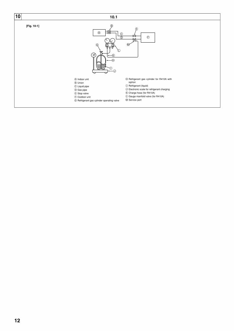
10.1. Gas charge[Fig. 10-1] (P.12)A Indoor unit
B Union
C Liquid pipe
D Gas pipe
E Stop valve
F Outdoor unit
G Refrigerant gas cylinder operating valve
H Refrigerant gas cylinder for R410A with siphon
I Refrigerant (liquid)
J Electronic scale for refrigerant charging
K Charge hose (for R410A)
L Gauge manifold valve (for R410A)
M Service port
1. Connect gas cylinder to the service port of stop valve (3-way).2. Execute air purge of the pipe (or hose) coming from refrigerant gas cylinder.3. Replenish specified amount of refrigerant, while running the air conditioner
for cooling.
Note:In case of adding refrigerant, comply with the quantity specified for the refrigeratingcycle.
Caution:• Do not discharge the refrigerant into the atmosphere.
Take care not to discharge refrigerant into the atmosphere during installa-tion, reinstallation, or repairs to the refrigerant circuit.
• For additional charging, charge the refrigerant from liquid phase of the gascylinder.If the refrigerant is charged from the gas phase, composition change mayoccur in the refrigerant inside the cylinder and the outdoor unit. In this case,ability of the refrigerating cycle decreases or normal operation can be impos-sible. However, charging the liquid refrigerant all at once may cause the com-pressor to be locked. Thus, charge the refrigerant slowly.
To maintain the high pressure of the gas cylinder, warm the gas cylinder with warmwater (under 40°C) during cold season. But never use naked fire or steam.
9. Test run
Indicates whether control power is supplied. Make sure that this LED is always lit.
Indicates whether power is supplied to the remote controller. This LED lights only in the case of
the indoor unit which is connected to the outdoor unit refrigerant address “0”.
Indicates state of communication between the indoor and outdoor units. Make sure that this LED is
always blinking.
LED 1 (power for microcomputer)
LED 2 (power for remote controller)
LED 3 (communication between indoor and outdoor units)
For description of each LED (LED1, 2, 3) provided on the indoor controller, refer to the following table.
9.4. AUTO RESTART FUNCTIONIndoor controller boardThis model is equipped with the AUTO RESTART FUNCTION.When the indoor unit is controlled with the remote controller, the operation mode,set temperature, and the fan speed are memorized by the indoor controller board.The auto restart function sets to work the moment the power has restored afterpower failure, then, the unit will restart automatically.Set the AUTO RESTART FUNCTION using the remote controller. (Mode no.01)
On the wireless remote controller with conditions above, following phenomena takes place.• No signals from the remote controller are accepted.• OPE lamp is blinking.• The buzzer makes a short ping sound.
Note:Operation is not possible for about 30 seconds after cancellation of function selection. (Correct operation)
01_KB79U749H01_GB.p65 2011.10.26, 4:49 PM24

01_KB79U749H01_GB.p65 2011.10.26, 4:49 PM25

01_KB79U749H01_GB.p65 2011.10.26, 4:49 PM26

01_KB79U749H01_GB.p65 2011.10.26, 4:49 PM27

KD79D905H02
Please be sure to put the contact address/telephone number on this manual before handing it to the customer.
HEAD OFFICE: TOKYO BLDG., 2-7-3, MARUNOUCHI, CHIYODA-KU, TOKYO 100-8310, JAPAN
KD79D905H01_Backcover.fm Page 24 Friday, October 14, 2011 10:11 AM