PDP-424MV - Pioneer USA, Car Stereo, Speakers, Home Theater, Navigation, DJ | Pioneer ...€¦ ·...
39
PDP-424MV Plasma Display Operating Instructions Contents related to system specifications, power requirements, accessories, and other information differ with respect to the country where this unit is purchased. For customers living in the U.S.A. or Canada, please use and refer to the instructions written in either English or French. For customers in Japan, please use and refer to the instructions written in Japanese.
Transcript of PDP-424MV - Pioneer USA, Car Stereo, Speakers, Home Theater, Navigation, DJ | Pioneer ...€¦ ·...

PDP-424MV
Plasma Display
Operating Instructions
Contents related to system specifications, power requirements,accessories, and other information differ with respect to thecountry where this unit is purchased. For customers living in theU.S.A. or Canada, please use and refer to the instructions writtenin either English or French. For customers in Japan, please useand refer to the instructions written in Japanese.

Engl
ish
En
Operating Instructions
Thank you very much for purchasing this PIONEER product.Before using your Plasma Display, please carefully read the“Important Information” and these “Operating Instructions” soyou will know how to operate the Plasma Display properly.Keep this manual in a safe place. You will find it useful in thefuture.
Note for Dealers:After installation, be sure to deliver this manual to the customerand explain to the customer how to handle the product.
Notes on Installation Work:This product is marketed assuming that it is installed by qualifiedpersonnel with enough skill and competence. Always have aninstallation specialist or your dealer install and set up the product.PIONEER cannot assume liabilities for damage caused by mistakein installation or mouting, misuse, modification or a natural disaster.

Engl
ish
Impo
rtan
t Inf
orm
atio
n
2En
iEn
PrecautionsPlease read this manual carefully before using your plasmamonitor and keep the manual handy for future reference.
CAUTIONRISK OF ELECTRIC SHOCK
DO NOT OPEN
CAUTION: TO REDUCE THE RISK OF ELECTRICSHOCK, DO NOT REMOVE COVER. NOUSER-SERVICEABLE PARTS INSIDE.REFER SERVICING TO QUALIFIEDSERVICE PERSONNEL.
This symbol warns the user that uninsulatedvoltage within the unit may have sufficientmagnitude to cause electric shock.Therefore, it is dangerous to make any kindof contact with any part inside of this unit.
This symbol alerts the user that importantliterature concerning the operation andmaintenance of this unit has been included.Therefore, it should be read carefully inorder to avoid any problems.
WARNINGTO PREVENT FIRE OR SHOCK HAZARDS, DO NOT EXPOSETHIS UNIT TO RAIN OR MOISTURE. ALSO DO NOT USETHIS UNIT’S POLARIZED PLUG WITH AN EXTENSION CORDRECEPTACLE OR OTHER OUTLETS, UNLESS THEPRONGS CAN BE FULLY INSERTED. REFRAIN FROMOPENING THE CABINET AS THERE ARE HIGH-VOLTAGECOMPONENTS INSIDE. REFER SERVICING TO QUALIFIEDSERVICE PERSONNEL.
WarningNot for use in a computer room as defined in the Standardfor the Protection of Electronic Computer/ Data ProcessingEquipment ANSI/NFPA 75.
This equipment has been tested and found to comply withthe limits for a Class B digital device, pursuant to Part 15 ofthe FCC Rules. These limits are designed to providereasonable protection against harmful interference in aresidential installation. This equipment generates, uses, andcan radiate radio frequency energy and, if not installed andused in accordance with the instructions, may cause harmfulinterference to radio communications. However, there is noguarantee that interference will not occur in a particularinstallation. If this equipment does cause harmful interferenceto radio or television reception, which can be determined byturning the equipment off and on, the user is encouraged totry to correct the interference by one or more of the followingmeasures:• Reorient or relocate the receiving antenna.• Increase the separation between the equipment and
receiver.• Connect the equipment into an outlet on a circuit different
from that to which the receiver is connected.• Consult the dealer or an experienced radio / TV technician
for help.
Important InformationWarnings and Safety PrecautionThis plasma monitor is designed andmanufactured to provide long, trouble-free service.No maintenance other than cleaning is required.Please see the section “Plasma monitor cleaningprocedure” on the next page.The plasma display panel consists of fine pictureelements (cells) with more than 99.99 percent activecells. There may be some cells that do not producelight or remain lit.For operating safety and to avoid damage to the unit,read carefully and observe the following instructions.To avoid shock and fire hazards:
1. Provide adequate space for ventilation to avoid internalheat build-up. Do not cover rear vents or install the unitin a closed cabinet or shelves. If you install the unit in an enclosure, make sure thereis adequate space at the top of the unit to allow hot airto rise and escape. If the monitor becomes too hot, theoverheat protector will be activated and the monitor willbe turned off. If this happens, turn off the power to themonitor and unplug the power cord. If the room wherethe monitor is installed is particularly hot, move themonitor to a cooler location, and wait for 60 minutes tocool the monitor. If the problem persists, contact yourdealer for service.
2. Do not use this unit’s polarized plug with extension cordsor outlets unless the prongs can be completely inserted.
3. Do not expose the unit to water or moisture.4. Avoid damage to the power cord, and do not attempt to
modify the power cord.5. Unplug the power cord during electrical storms or if
the unit will not be used over a long period.6. Do not open the cabinet which has potentially dangerous
high voltage components inside. If the unit is damaged inthis way the warranty will be void. Moreover, there is aserious risk of electric shock.
7. Do not attempt to service or repair the unit. Themanufacturer is not liable for any bodily harm or damagecaused if unqualified persons attempt service or openthe back cover. Refer all service to authorized ServiceCenters.

Engl
ish
Impo
rtan
t Inf
orm
atio
n
3En
iiEn
To avoid damage and prolong operating life:1. Use only with 100-240V 50/60Hz AC power supply.
Continued operation at line voltages greater than 100-240 Volts AC will shorten the life of the unit, and mighteven cause a fire hazard.
2. Handle the unit carefully when installing it and do notdrop.
3. Set the unit away from heat, excessive dust, and directsunlight.
4. Protect the inside of the unit from liquids and smallmetal objects. In case of accident, unplug the powercord and have it serviced by an authorized ServiceCenter.
5. Do not hit or scratch the panel surface as this causesflaws on the surface of the screen.
6. For correct installation and mounting it is stronglyrecommended to use a trained, authorized dealer.
7. As is the case with any phosphor-based display (like aCRT monitor, for example) light output will graduallydecrease over the life of a Plasma Display Panel.
8. To avoid sulfurization it is strongly recommended not toplace the unit in a dressing room in a public bath or hotspring bath.
9. Do not use in a moving vehicle, as the unit could drop ortopple over and cause injuries.
10. Do not place the unit on its side, upside-down or with thescreen facing up or down, to avoid combustion or electricshock.
Plasma monitor cleaning procedure:1. Use a wiping cloth (attached) or a soft dry cloth to clean
the front panel and bezel area. Never use solvents such asalcohol or thinner to clean these surfaces.
2. Clean plasma ventilation areas with a vacuum cleanerwith a soft brush nozzle attachment.
NOTE:When you connect a computer to this monitor, use an RGBcable including the ferrite core on both ends of the cable.And regarding DVI and power cable, attach the suppliedferrite cores. If you do not do this, this monitor will notconform to mandatory FCC standards.Attaching the ferrite cores:Set the ferrite cores on both ends of the DVI cable (notsupplied), and both ends of the power cable (supplied).Close the lid tightly until the clamps click.Use the band to fasten the ferrite core (supplied) to theDVI cable.
DVI cable (not supplied)
core (small) core (small)
Connectorband band
Power cable (supplied) core (large)
core (large)
3. To ensure proper ventilation, cleaning of the ventilationareas must be carried out monthly. More frequent cleaningmay be necessary depending on the environment in whichthe plasma monitor is installed.
Recommendations to avoid or minimize phosphor burn-in:Like all phosphor-based display devices and all other gasplasma displays, plasma monitors can be susceptible tophosphor burn under certain circumstances. Certainoperating conditions, such as the continuous display of astatic image over a prolonged period of time, can result inphosphor burn if proper precautions are not taken. To protectyour investment in this plasma monitor, please adhere to thefollowing guidelines and recommendations for minimizingthe occurrence of image burn:
* Always enable and use your computer’s screen saverfunction during use with a computer input source.
* Display a moving image whenever possible.* Change the position of the menu display from time to time.* Always power down the monitor when you are finished
using it.
If the plasma monitor is in long term use or continuousoperation take the following measures to reduce thelikelihood of phosphor burn:
* Lower the Brightness and Contrast levels as much aspossible without impairing image readability.
* Display an image with many colors and color gradations(i.e. photographic or photo-realistic images).
* Create image content with minimal contrast between lightand dark areas, for example white characters on blackbackgrounds. Use complementary or pastel color wheneverpossible.
* Avoid displaying images with few colors and distinct,sharply defined borders between colors.
* Note: Burn-in is not covered by the warranty.
Contact your dealer for other recommended procedures thatwill best suit your particular application needs.
Information to User
Alteration or modifications carried out without appro-
priate authorization may invalidate the user's right to
operate the equipment.
WARNING:
Handling the cord on this product or cords associated
with accessories sold with the product will expose you
to lead, a chemical known to the State of California and
other governmental entities to cause cancer and birth
defects or other reproductive harm. Wash hands after
handling.
CAUTION:
WHEN POSITIONING THIS EQUIPMENT ENSURE THAT
THE MAINS PLUG AND SOCKET IS EASILY ACCES-
SIBLE.
Engl
ish
Impo
rtan
t Inf
orm
atio
n
4En
iiiEn
DECLARATION OF CONFORMITY
This device complies with Part 15 of FCC Rules. Operation is subject to the following two conditions. (1) This device maynot cause harmful interference, and (2) this device must accept any interference received, including interference that maycause undesired operation.
U.S. Responsible Party:Address:
Tel. No.:
PIONEER ELECTRONICS (USA) INC.P.O. BOX 1760, LONG BEACH, CA., 90801-1760 U.S.A.800 (421-1625)
Type of Product:
Equipment Classification:
Models:
Plasma Display
Class B Peripheral
PDP-424MV
We hereby declare that the equipment specified aboveconforms to the technical standards as specified in the FCC Rules.
IMPORTANT NOTICE
The serial number for this equipment is located on the
rear panel. Please write this serial number on your en-
closed waranty card and keep in a secure place. This is
for your security.
This Class B digital apparatus complies with Canadian
ICES-003.
CautionThis model is for use with the following optional accessories.Use with other optional accessories is capable of resulting ininstability causing possible injury.
Speakers: PDP-S32-LRTable top stand: PDK-TS09Wall mount unit: PDK-WM04Tilt mount unit: PDK-WT01Ceiling mount unit: PDK-CK01

Engl
ish
Impo
rtan
t Inf
orm
atio
n
5En
ivEn
IMPORTANT SAFETY INSTRUCTIONSRead before operating equipment
1. Read these instructions.2. Keep these instructions.3. Heed all warnings.4. Follow all instructions.5. Do not use this apparatus near water.6. Clean only with a dry cloth.7. Do not block any of the ventilation openings. Install in
accordance with the manufacturers instructions.8. Do not install near any heat sources such as radiators,
heat registers, stoves, or other apparatus (includingamplifiers) that produce heat.
9. Do not defeat the safety purpose of the polarized orgrounding-type plug. A polarized plug has two bladeswith one wider than the other. A grounding type plughas two blades and third grounding prong.The wideblade or third prong are provided for your safety. Whenthe provided plug does not fit into your outlet, consultan electrician for replacement of the obsolete outlet.
10. Protect the power cord from being walked on or pinchedparticularly at plugs, convenience receptacles, and thepoint where they exit from the apparatus.
11. Only use attachments/accessories specified by themanufacturer.
12. Use only with a cart, stand, tripod, bracket,or table specified by the manufacturer, or soldwith the apparatus.When a cart is used, usecaution when moving the cart/apparatus
combination to avoid injury from tip-over.13. Unplug this apparatus during lightning storms or when
unused for long periods of time.14. Refer all servicing to qualified service personnel.
Servicing is required when the apparatus has beendamaged in any way, such as power-supply cord or plugis damaged, liquid has been spilled or objects have falleninto apparatus, the apparatus has been exposed to rainor moisture, does not operate normally, or has beendropped.
15. Damage Requiring Service - The appliance should beserviced by qualified service personnel when:A. The power supply cord or the plug has been damaged;
orB. Objects have fallen, or liquid has been spilled into
the appliance; orC. The appliance has been exposed to rain; orD. The appliance does not appear to operate normally
or exhibits a marked change in performance; orE. The appliance has been dropped, or the enclosure
damaged.16. Tilt/Stability - All televisions must comply with
recommended international global safety standards fortilt and stability properties of its cabinets design.• Do not compromise these design standards by
applying excessive pull force to the front, or top, ofthe cabinet which could ultimately overturn theproduct.
• Also, do not endanger yourself, or children, by placingelectronic equipment/toys on the top of the cabinet.Such items could unsuspectingly fall from the top ofthe set and cause product damage and/or personalinjury.
17. Wall Mounting - The appliance should be mounted to awall only as recommended by the manufacturer.
18. Power Lines - An outdoor antenna should be locatedaway from power lines.
19. Outdoor Antenna Grounding - If an outside antenna isconnected to the receiver, be sure the antenna system isgrounded so as to provide some protection againstvoltage surges and built up static charges.Section 810 of the National Electric Code, ANSI/NFPANo. 70- 1984, provides information with respect to propergrounding of the mats and supporting structuregrounding of the lead-in wire to an antenna-dischargeunit, size of grounding connectors, location of antenna-discharge unit, connection to grounding electrodes andrequirements for the grounding electrode.
20. Objects and Liquid Entry - Care should be taken so thatobjects do not fall and liquids are not spilled into theenclosure through openings.
Apparatus shall not be exposed to dripping or splashingand that no objects filled with liquids, such as vases, shallbe placed on apparatus.
WARNINGTo reduce the risk of fire or electric shock, do not exposethis apparatus to rain or moisture.

Engl
ish
Impo
rtan
t Inf
orm
atio
n
6En
Should this product require service in the U.S.A. and you wish to locate the nearest Pioneer Authorized Independent Service Company, or if you wish to purchase replacement parts, operating instructions, service manuals, or accessories, please call the number shown below.
8 0 0 – 4 2 1 – 1 6 2 5
Please do not ship your product to Pioneer without first calling Pioneer Electronics (USA) Inc. at the above listed number for assistance.
Pioneer Electronics (USA) Inc.P.O. BOX 1760, Long Beach,CA 90801-1760, U.S.A.
For warranty information please see the Limited Warranty sheet included with your product.
Should this product require service in Canada, please contact a Pioneer Canadian Authorized Dealer to locate the nearest Pioneer Authorized Service Company in Canada.Alternatively, please contact the Customer Satisfaction Department at the following address:
Pioneer Electronics of Canada, Inc.Customer Satisfaction Department300 Allstate Parkway, Markham, Ontario L3R OP2(905)479-44111(877)283-5901
For warranty information please see the Limited Warranty sheet included with your product.S021_EF
vEn

Engl
ish
Cont
ents
1En
ContentsInstallation ...................................................... 2
Ventilation Requirements for enclosure mounting .......... 2How to use the safety metal fittings and the screws for
safety metal fittings ................................................ 2Creating a video wall ............................................... 3Cable Management .................................................. 3Caution on when the plasma monitor is installed vertically ... 4How to use the remote control .................................... 4
Battery Installation and Replacement ........................... 4Using the wired remote control mode .......................... 4Operating Range .......................................................... 4Handling the remote control ......................................... 4
Part Names and Function .................................. 5Front View .............................................................. 5Rear View/ Terminal Board ....................................... 6Remote Control ........................................................ 7
Basic Operations ............................................... 8POWER .................................................................. 8
To turn the unit ON and OFF: ...................................... 8VOLUME ................................................................ 8
To adjust the sound volume: ......................................... 8MUTING ................................................................. 8
To mute the sound: ....................................................... 8DISPLAY .................................................................. 8
To check the settings: ................................................... 8DIGITAL ZOOM ....................................................... 8AUTO SET UP .......................................................... 8
To adjust the size or quality of the picture automatically: ...... 8OFF TIMER .............................................................. 8
To set the off timer: ...................................................... 8To check the remaining time: ....................................... 8To cancel the off timer: ................................................ 8
WIDE Operations ............................................... 9SCREEN SIZE Operation (manual) ............................. 9
When viewing videos or digital video discs ................. 9SCREEN SIZE Operation with Computer Signals ........ 10
OSD (On Screen Display) Controls ..................... 11Menu Operations ................................................... 11Setting the language for the menus ........................... 11Menu Tree ............................................................. 12Picture Settings Menu .............................................. 14
Adjusting the picture .................................................. 14Setting the picture modes according to
the brightness of the room ....................................... 14Reducing noise in the picture ..................................... 14Setting the color temperature ..................................... 14Adjusting the color to the desired level ...................... 15Changing the Gamma Curve ...................................... 15Making the Low Tone adjustments ............................ 15Adjusting the colors ................................................... 15
SOUND Settings Menu ........................................... 16Adjusting the treble, bass and left/right balance
and audio input select .............................................. 16Setting the allocation of the audio connectors ............ 16
SCREEN Settings Menu ........................................... 16Adjusting the Position, Size, PHASE, CLOCK ................ 16
Option1 Settings Menu ........................................... 17Setting the on-screen display ...................................... 17Setting the PC2/COMPONENT2 connectors ............. 17Checking the signal being transmitted to PC1 terminal ....... 17Setting a computer image to the correct RGB select screen ...... 17Setting high definition images to the suitable screen size .... 18Setting the Input Skip ................................................. 18Resetting to the default values .................................... 18
Option2 Settings Menu ........................................... 19Setting the power management for computer images ..... 19STANDBY/ON indicator ........................................... 19Setting the picture to suit the movie ........................... 19Reducing burn-in of the screen .................................. 19Setting the gray level for the SIDE MASK ................ 21Setting the screen size for S1/S2 video input .............. 22Setting the signal and black level for DVI signal ........ 22
Option3 Settings Menu ........................................... 22Using the timer .......................................................... 22Setting the power on mode ......................................... 23Enabling/disabling the front panel controls ................ 23Enabling/disabling remote control wireless transmission .... 24Loop Out setting ........................................................ 24ID number setting ...................................................... 24Video Wall setting ...................................................... 24
Advanced OSD Settings Menu ................................. 27Setting the menu mode .............................................. 27
Color System Settings Menu .................................... 27Setting the video signal format ................................... 27
Source Information Menu ........................................ 27Checking the frequencies, polarities of input signals,
and resolution .......................................................... 27
Pin Assignments ............................................. 28mini D-Sub 15-pin connector (Analog) ..................... 28DVI-D 24-pin connector (Digital) .............................. 28
Table of Signals Supported .............................. 29Troubleshooting.............................................. 31Specifications ................................................. 32
Contents of the Package� Plasma monitor� Power cord� Remote control with two AAA Batteries� Manual� Warranty� Safety metal fittings (2pcs)*
� Ferrite cores (large 2pcs, small 2pcs)� Bands (2pcs)� Wiping cloth
* These are fittings for fastening the unit to a wall to preventtipping due to external shock when using the stand(optional). Fasten the safety fittings to the holes in theback of the monitor using the safety fitting mount screws(see page 2).
Options• Stand• Speakers• Wall mount unit• Tilt mount unit• Ceiling mount unit

Engl
ish
Inst
alla
tion
2En
50mm (2")
50m
m (
2")
50m
m (
2")
Wall
Wall
50mm (2")
50mm (2")
You can attach your optional mounts or stand to the plasma monitor in one of the following two ways:* While it is upright. (See Drawing A)* As it is laid down with the screen face down (See Drawing B). Lay the protective sheet, which was wrapped around the
monitor when it was packaged, beneath the screen surface so as not to scratch the screen face.* Do not touch or hold the screen face when carrying the unit.
• This device cannot be installed on its own. Be sure to use a stand or original mounting unit. (Wallmount unit, Stand, etc.)
* See page 1.• For correct installation and mounting it is strongly recommended to use a trained, authorized
dealer.Failure to follow correct mounting procedures could result in damage to the equipment or injuryto the installer.Product warranty does not cover damage caused by improper installation.
* Use only the mounting kit or stand provided by manufacturer and listed under Options.
Drawing BDrawing A
How to use the safety metal fittingsand the screws for safety metalfittingsThese are fittings for fastening the unit to a wall to preventtipping due to external shock when using the stand(optional). Fasten the safety fittings to the holes in theback of the monitor using the safety fitting mount screws.
Screw hole
Wall
Table Top
Safty metal fittings
Screw for Safty metalfittings
Metal chain(Not supplied)
Screw or Hook etc.(Not supplied)
Ventilation Requirements forenclosure mountingTo allow heat to disperse, leave space between surroundingobjects as shown on the diagram below when installing.
Installation

Engl
ish
Inst
alla
tion
3En
Note:1. The VIDEO1 and PC1 terminals can be used for either INPUT or OUTPUT.
When LOOP OUT is ON, do not connect an OUTPUT signal from another unit, that will place an extraordinary load onthe other unit and may damage it.
2. LOOP OUT can not be turned ON while signals are input to the PC1 terminal.3. LOOP OUT can be turned ON while signals are input to the PC1 terminal if the POWER is switched ON.
Information• To loop signals out to another plasma display, set the LOOP OUT to ON.• To create a video wall, set the VIDEO WALL menu items properly.• To connect monitors, please use a 1~2m (3.3~6.6 feet) BNC cable (any commercially available cable).• If the image quality is poor, do not use the monitor’s out terminal. Use a distribution amplifier (any commercially
available distribution amplifier) to connect the split signals to the respective monitor INPUT terminals.• Being used as a video wall function, maximaly 4-screen is rough-standard with lower than 1024�768, 60Hz
signal.• A distribution amplifier is particularly recommended when using 9-screen and over video wall.• From the second monitor onward, connections require a BNC-RCA conversion cable or connector, a mini D-Sub
15 pin cable-BNC (�5) cable or a conversion connector.
Creating a video wallWith built-in matrix display capability, you can create a 4-25 video wall.• Connect signal cables and remote cables as shown below.
Video signal PC/COMPONENT signal
BNC connector
RCA phono plug
OUT
VIDEO signalIN
OUT Remotecontrol
VIDEO signal
Remote INcontrol
BNC connector
PC signal / IN
OUT
OUT Remotecontrol
COMPONENTsignal
PC signal /COMPONENTsignal
INRemotecontrol
Cable ManagementUsing the cable clamps provided with the plasma display,bundle at the back of the unit the signal and audio cablesconnected to the display.
Back of the unit
mounting hooks
clamp
mounting hook cables
To attach To detach
1. 2.

Engl
ish
Inst
alla
tion
4En
OPTION1
RETURNSEL. OK
: RGB
: RGB
: AUTO
: 1080B
: OFF
: OFF 1024 768
EXIT
OSD
BNC INPUT
D-SUB INPUT
RGB SELECT
HD SELECT
INPUT SKIP
ALL RESET
MENU
Bottom side
Top sideCaution on when the plasma monitor is installed vertically• Use the optional unit. Contact your store of purchase when installing.• Rotate 90° clockwise as seen from the front when installing.• After installing, check with the PIONEER logo mark
as seen from the front.• Be sure to set “OSD ANGLE” to “V” when using.* Failure to heed the above cautions may lead to malfunction.
How to use the remote controlBattery Installation and ReplacementInsert the 2 “AAA” batteries, making sure to set them inwith the proper polarity.1.Press and open the cover.
2.Align the batteries according to the (+) and (–) indicationinside the case.
3.Replace the cover.
* The 1/8 Stereo Mini cable must be purchased separately.
Operating Range* Use the remote control within a distance of about 7 m/
23ft. from the front of the monitor’s remote control sensorand at horizontal and vertical angles of up to approximately30°.
* The remote control operation may not function if themonitor’s remote control sensor is exposed to directsunlight or strong artificial light, or if there is an obstaclebetween the sensor and the remote control.
Handling the remote control• Do not drop or mishandle the remote control.• Do not get the remote control wet. If the remote control
gets wet, wipe it dry immediately.• Avoid heat and humidity.• When not using the remote control for a long period,
remove the batteries.• Do not use new and old batteries together, or use different
types together.• Do not take apart the batteries, heat them, or throw them
into a fire.• When using the remote control in the wireless condition,
be sure to unplug the remote cable from the REMOTEIN terminal on the monitor.
• When disposing of used batteries, please comply withgovernmental regulations or environmental publicinstruction’s rules that apply in your country/area.
Using the wired remote control modeConnect the remote cable* to the remote control’s remotejack and the “REMOTE IN” terminal on the monitor.When the cable is connected, the mode automaticallyswitches to wired remote control. When the wired remotecontrol mode is used, the remote control can be operatedeven if no batteries are loaded.

Engl
ish
Part
Nam
es a
nd F
unct
ion
5En
q Power ( )Turns the monitor’s power on and off.
w Remote sensor windowReceives the signals from the remote control.
e STANDBY/ON indicatorWhen the power is on ............................. Lights green.When the power is in the standby mode ... Lights red.
r INPUT/EXITSwitches the input.The available inputs depend on the setting of “BNCINPUT”, “RGB SELECT” and “DVI SET-UP”.Functions as the EXIT buttons in the On-ScreenDisplay (OSD) mode.
Front View
4567 1 3 2
t LEFT/– and RIGHT/+Functions as the CURSOR (� / �) buttons in the On-Screen Display (OSD) mode.
y VOLUME and Adjusts the volume. Functions as the CURSOR (�/�) buttons in the On-Screen Display (OSD) mode.
u MENU/SETSets the On-Screen Display (OSD) mode and displaysthe main menu.
WARNINGThe Power on/off switch does not disconnect the plasmadisplay completely from the supply mains.
Part Names and Function

Engl
ish
Part
Nam
es a
nd F
unct
ion
6En
A AC INConnect the included power cord here.
B EXT SPEAKER L and RConnect speakers (optional) here. Maintain the correctpolarity. Connect the (positive) speaker wire to the
EXT SPEAKER terminal and the (negative)speaker wire to the EXT SPEAKER terminal onboth LEFT and RIGHT channels.Please refer to your speaker’s owner’s manual.
C VIDEO1, 2, 3 (BNC, RCA, S-Video)Connect VCR’s, DVD’s or Video Cameras, etc. here.VIDEO1 can be used for Input or Output (see page24).
D AUDIO1, AUDIO2, AUDIO3These are audio input terminals.The input is selectable. Set which video image to allotthem from the SOUND menu screen.
E COMPONENT1Connect DVD’s, High Definition or Laser Discs, etc.here.
F PC2/COMPONENT2PC2: You can connect an analog RGB signal
and the syncronization signal.COMPONENT2: You can connect DVDs, High
Definition sources, Laser Discs, etc.here.This input can be set for use with anRGB or component source (see page17).
G PC1 (mini D-Sub 15pin)Connect an analog RGB signal from a computer, etc.here. This input can be used for Input or Output (seepage 24).
H PC3 (DVI 24pin)Connect a digital signal (TMDS) from a source with aDVI output.
I RS-232CNever connect any component to this connectorwithout first consulting your Pioneer installationtechnician.This connector is used for plasma display setupadjustments.
J REMOTE INConnect the remote cable* to the remote control’sremote jack to obtain wired remote control.
K REMOTE OUTConnect the remote cable* to the REMOTE IN jack ofthe other display monitor to obtain wired remotecontrol.
* The 1/8 Stereo Mini cable must be purchased separately.
Rear View/ Terminal Board

Engl
ish
Part
Nam
es a
nd F
unct
ion
7En
q POWER ON/STANDBYSwitches the power on/standby.(This does not operate when STANDBY/ON indicatorof the main unit is off.)
w RGB/PCPress this button to select RGB/PC as the source.RGB/PC can also be selected using the INPUT/EXITbutton on the monitor.
e COMPONENTPress this button to select COMPONENT as the source.COMPONENT can also be selected using the INPUT/EXIT button on the monitor.
r VIDEOPress this button to select VIDEO as the source.
VIDEO can also be selected using the INPUT/EXITbutton on the monitor.
t MENU/SETPress this button to access the OSD controls.Press this button during the display of the main menuto go to the sub menu.
y CURSOR (� / � / � / �)Use these buttons to select items or settings and toadjust settings.
u EXITPress this button to exit the OSD controls in the mainmenu. Press this button during the display of the submenu to return to the previous menu.
i POINT ZOOMPress this button to display the pointer.
o ZOOM (+ /–)Enlarges or reduces the image.
!0 VOLUME (+ /–)Adjusts the sound volume.
!1 MUTINGMutes the sound.
!2 SCREEN SIZEAutomatically detects the signal and sets the aspect ratio.SCREEN SIZE button is not active for all signals.
!3 DISPLAYDisplays the source settings on the screen.
!4 OFF TIMERActivates the off timer for the unit.
!5 AUTO SET UPPress this button to adjust PHASE, CLOCK, Position,and Contrast automatically, or to switch the screen sizeto ZOOM mode automatically with the superimposedcaption displayed fully only when the picture containsdark areas above and below the picture.
!6 ID NO. SETSet the ID number in the remote control. The remotecontrol can then be used only for a display with thesame ID number. When several displays are usedtogether they can be controlled individually.
!7 CLEARClears the number set by the ID NO. SET button.
!8 Remote control signal transmitterTransmits the remote control signals.
!9 Remote JackInsert the plug of the remote cable (The 1/8 StereoMini cable) here when using the supplied remotecontrol in the wired condition.
Remote Control
→ VIDEO1 → VIDEO2 → VIDEO3
Engl
ish
Bas
ic O
pera
tions
8En
Basic OperationsPOWERTo turn the unit ON and OFF:1. Plug the power cord into an active AC power outlet.2. Press the Power button (on the unit).
The monitor’s STANDBY/ON indicator turns red and thestandby mode is set.
3. Press the POWER ON button (on the remote control) toturn on the unit.The monitor’s STANDBY/ON indicator will light up(green) when the unit is on.
4. Press the POWER STANDBY button (on the remote control)or the Power button (on the unit) to turn off the unit.The monitor’s STANDBY/ON indicator turns red and thestandby mode is set (only when turning off the unit withthe remote control).
VOLUMETo adjust the sound volume:1. Press and hold the VOLUME button (on the remote
control or the unit) to increase to the desired level.2. Press and hold the VOLUME button (on the remote
control or the unit) to decrease to the desired level.
MUTINGTo mute the sound:Press the MUTING button on the remote control to mutethe sound; press again to restore.
DISPLAYTo check the settings:1. The screen changes each time the DISPLAY button is
pressed.2. If the button is not pressed for approximately three seconds,
the menu turns off.
DIGITAL ZOOMDigital zoom specifies the picture position and enlargesthe picture.1. Press the POINT ZOOM button to display the pointer.
( )To change the size of the picture:
Press the ZOOM+ button and enlarge the picture.The pointer will change to resemble a magnifying glass.( )A press of the ZOOM- button will reduce the pictureand return it to its original size.
To change the picture position:Select the position with the ��� � buttons.
2. Press the POINT ZOOM button to delete the pointer.
AUTO SET UPTo adjust the size or quality of the pictureautomatically:Press the AUTO SET UP button.
Information� AUTO SET UP ON settingWhen RGB (still picture) input is selected:PHASE, CLOCK, Position, and Contrast will beadjusted automatically.When RGB (motion picture), VIDEO, or Y/Pb/Pr(component) input is selected:The screen size switches to ZOOM mode automaticallywith the superimposed caption displayed fully onlywhen the picture contains dark areas above and belowthe picture.
OFF TIMERTo set the off timer:The off timer can be set to turn the power off after 30, 60,90 or 120 minutes.1. Press the OFF TIMER button to start the timer at 30
minutes.2. Press the OFF TIMER button to the desired time.3. The timer starts when the menu turns off.
→ 30 → 60 → 90 → 120 → 0
OFF TIMER 30
To check the remaining time:1. Once the off timer has been set, press the OFF TIMER
button once.2. The remaining time is displayed, then turns off after a few
seconds.3. When five minutes remain the remaining time appears
until it reaches zero.
OFF TIMER 28
To cancel the off timer:1. Press the OFF TIMER button twice in a row.2. The off timer is canceled.
OFF TIMER 0
Note:After the power is turned off with the off timer ...A slight current is still supplied to the monitor. When youare leaving the room or do not plan to use the system for along period of time, turn off the power of the monitor.
Engl
ish
WID
E O
pera
tions
9En
SCREEN SIZE Operation (manual)With this function, you can select one of six screen sizes.
When viewing videos or digital video discs1. Press the SCREEN SIZE button on the remote control.2. Within 3 seconds ...
Press the SCREEN SIZE button again.The screen size switches as follows:
→ 4:3 → FULL → WIDE → ZOOM → 2.35:1 → 14:9
When a 720P or 1080I signal is input:
FULL ↔ 2.35:1
4:3 size screen
The normal size screen is displayed.* The picture has the same size as video pictures with a 4 : 3
aspect ratio.
FULL size screen
The image is expanded in the horizontal direction.* Images compressed in the horizontal direction (“squeezed
images”) are expanded in the horizontal direction anddisplayed on the entire screen with correct linearity.(Normal images are expanded in the horizontal direction.)
WIDE size screen
The picture is expanded in the horizontal and verticaldirections at different ratios.* Use this for watching normal video programs (4:3) with a
wide screen.
ZOOM size screen
The picture is expanded in the horizontal and verticaldirection, maintaining the original proportions.* Use this for theater size (wide) movies, etc.
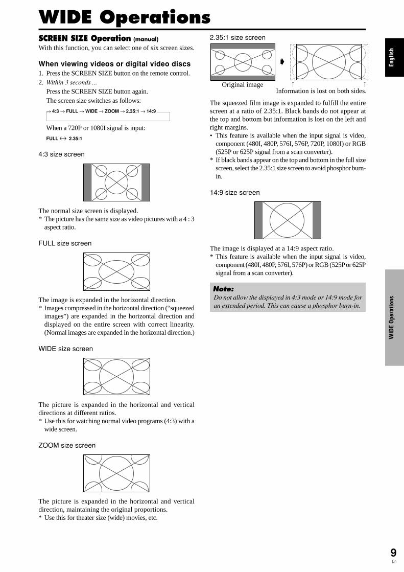
2.35:1 size screen
The squeezed film image is expanded to fulfill the entirescreen at a ratio of 2.35:1. Black bands do not appear atthe top and bottom but information is lost on the left andright margins.• This feature is available when the input signal is video,
component (480I, 480P, 576I, 576P, 720P, 1080I) or RGB(525P or 625P signal from a scan converter).
* If black bands appear on the top and bottom in the full sizescreen, select the 2.35:1 size screen to avoid phosphor burn-in.
14:9 size screen
The image is displayed at a 14:9 aspect ratio.* This feature is available when the input signal is video,
component (480I, 480P, 576I, 576P) or RGB (525P or 625Psignal from a scan converter).
Note:Do not allow the displayed in 4:3 mode or 14:9 mode foran extended period. This can cause a phosphor burn-in.
Information is lost on both sides.Original image
�
WIDE Operations

Engl
ish
WID
E O
pera
tions
10En
Information� Supported resolutionSee page 29 for details on the display output of thevarious VESA signal standards supported by themonitor.� When 852 (848) dot � 480 line wide VGA*signals with a vertical frequency of 60 Hz andhorizontal frequency of 31.7 (31.0) kHz are in-putSelect an appropriate setting for RGB SELECT modereferring to the“Table of Signals Supported” on page29.
* “VGA”, “SVGA” and “SXGA” are registeredtrademarks of IBM, Inc. of the United States.
Note:Do not allow the displayed in 4:3 mode or 14:9 mode foran extended period. This can cause a phosphor burn-in.
SCREEN SIZE Operation withComputer SignalsSwitch to the wide screen mode to expand the 4 : 3 imageto fill the entire screen.
1.Press the SCREEN SIZE button on the remote control.
2.Within 3 seconds ...
Press the SCREEN SIZE button again.The screen size switches as follows:→ 4:3 → FULL → ZOOM
4:3 size screen (4:3 or SXGA 5:4)
The picture has the same size as the normal computer image.
FULL size screen
The image is expanded in the horizontal direction.
ZOOM size screen
When wide signals are input.
FULL size screen

Engl
ish
OSD
(On
Scre
en D
ispl
ay) C
ontr
ols
11En
Menu OperationsThe OSD window is displayed with respect to thescreen as shown on the diagram.
* Depending on the screen’s mode, the OSD may bedisplayed differently.In the explanation, the OSD section is shown close up.
MAIN MENU 1 / 2
EXIT
PICTURESOUNDSCREENOPTION1
ADVANCED OSD NEXT PAGE
: OFF
SEL. EXITOKMENU
The following describes how to use the menus and theselected items.1. Press the MENU/SET button on the remote control to
display the MAIN MENU.
MAIN MENU 1 / 2
EXIT
PICTURESOUNDSCREENOPTION1
ADVANCED OSD NEXT PAGE
: OFF
SEL. EXITOKMENU
MAIN MENU 2 / 2 PREVIOUS PAGELANGUAGECOLOR SYSTEMSOURCE INFORMATION
SEL. EXIT EXITOKMENU
2. Press the cursor buttons � � on the remote control tohighlight the menu you wish to enter.
3. Press the MENU/SET button on the remote control toselect a sub menu or item.
PICTURE 1 / 2CONTRASTBRIGHTNESSSHARPNESSCOLORTINTAV SELECTIONDNR NEXT PAGE
: STD: OFF
SEL. ADJ. EXIT RETURN
4. Adjust the level or change the setting of the selected itemby using the cursor buttons � � on the remote control.
5. The adjustments or the settings that are stored in memory.The change is stored until you change it again.
6. Repeat steps 2 – 5 to adjust an additional item, or pressthe EXIT button on the remote control to return to themain menu.
* When adjusting using the bar at the bottom of the screen,press the � or � button within 5 seconds. If not, thecurrent setting is set and the previous screen appears.
Note: The main menu disappears by pressing the EXITbutton.
Information� Advanced menu modeWhen “ADVANCED OSD” is set to “ON” in the mainmenu (1/2), full menu items will be shown.
MAIN MENU 1 / 2PICTURESOUNDSCREENOPTION1OPTION2OPTION3ADVANCED OSD NEXT PAGE
: ON
SEL. EXIT EXITOKMENU
OSD (On Screen Display) Controls
Setting the language for the menusThe menu display can be set to one of seven languages.
Example: Setting the menu display to “DEUTSCH”
On “MAIN MENU”, select “LANGUAGE”, then press theMENU/SET button.The “LANGUAGE” screen appears.On “LANGUAGE”, select “ DEUTSCH”, then press theMENU/SET button.
LANGUAGE
LANGUAGE: DEUTSCH
EXIT RETURNOKMENUADJ.
The “LANGUAGE” is set to “DEUTSCH” and return to themain menu.
Information� Language settingsENGLISH ........ EnglishDEUTSCH....... GermanFRANÇAIS ...... FrenchESPAÑOL ....... Spanish
ITALIANO ........ ItalianSVENSKA ....... Swedish
................ Japanese

Engl
ish
OSD
(On
Scre
en D
ispl
ay) C
ontr
ols
12En
Main menu Sub menu Sub menu 2 Sub menu 3 Sub menu 4 RESET REFERENCE
PICTURE CONTRAST �←→ 0←52→72 YES 14BRIGHTNESS �←→ 0←32→64 YES 14SHARPNESS �←→ 0←16→32 YES 14COLOR �←→ 0←32→64 YES 14TINT R←→G 0←32→64 YES 14AV SELECTION DYNAMIC/STD/MOVIE1/MOVIE2/DEFAULT YES 14DNR OFF/LOW/MID/HIGH YES 14COLOR TEMP. LOW/MID LOW/MID/HIGH YES 14WHITE BALANCE R.HIGH �←→ 0←40→70 YES 15
G.HIGH �←→ 0←40→70 YES 15B.HIGH �←→ 0←40→70 YES 15R.LOW �←→ 0←40→70 YES 15G.LOW �←→ 0←40→70 YES 15B.LOW �←→ 0←40→70 YES 15RESET OFF←→ON YES 15
GAMMA 1←→2←…→4 YES 15LOW TONE AUTO←→1←…→3 YES 15C. DETAIL ADJ RED Y←→M 0←32→64 YES 15
GREEN C←→Y 0←32→64 YES 15BLUE M←→C 0←32→64 YES 15YELLOW G←→R 0←32→64 YES 15MAGENTA R←→B 0←32→64 YES 15CYAN B←→G 0←32→64 YES 15RESET OFF←→ON YES 15
Main menu Sub menu Sub menu 2 Sub menu 3 Sub menu 4 RESET REFERENCE
SOUND BASS �←→ 0←13→26 YES 16TREBLE �←→ 0←13→26 YES 16BALANCE L←→R -22←0→+22 YES 16AUDIO INPUT1 VIDEO 1-3 / COMPNT 1-2 / PC1DSUB / PC2-BNC / PC3-DVI YES 16AUDIO INPUT2 VIDEO 1-3 / COMPNT 1-2 / PC1DSUB / PC2-BNC / PC3-DVI YES 16AUDIO INPUT3 VIDEO 1-3 / COMPNT 1-2 / PC1DSUB / PC2-BNC / PC3-DVI YES 16
Main menu Sub menu Sub menu 2 Sub menu 3 Sub menu 4 RESET REFERENCE
SCREEN SCREEN SIZE 4:3/FULL/WIDE/ZOOM/2.35:1/14:9 — 16V.POSITION �←→ -64←0→+64 YES 16H.POSITION �←→ -128←0→+127 YES 16V.SIZE �←→ 0←→64 YES 16H.SIZE �←→ 0←→64 YES 16AUTO PICTURE OFF←→ON*2 NO 16PHASE*1 �←→*2 0←→64 YES 16CLOCK*1 �←→*2 0←64→128 YES 16
Main menu Sub menu Sub menu 2 Sub menu 3 Sub menu 4 RESET REFERENCE
OPTION1 OSD DISPLAY OSD OFF←→ON YES 17OSD ADJUST 1←…→6 YES 17OSD ANGLE H←→V YES 17OSD ORBITER OFF←→ON YES 17OSD CONTRAST LOW←→NORMAL YES 17
BNC INPUT RGB←→COMP. YES 17D-SUB INPUT RGB — 17RGB SELECT AUTO/STILL/MOTION/WIDE1/WIDE2/WIDE3/WIDE4/DTV YES 17HD SELECT 1080B/1035I/1080A NO 18INPUT SKIP OFF←→ON YES 18ALL RESET OFF←→ON — 18
:Shaded areas indicate the default value.�←→: Press the � or � button to adjust. :Menu items in a ruled box are available when the ADVANCED OSD is set to ON.
Menu Tree

Engl
ish
OSD
(On
Scre
en D
ispl
ay) C
ontr
ols
13En
*1 Only when AUTO PICTURE is OFF*2 RGB/PC only
Main menu Sub menu Sub menu 2 Sub menu 3 Sub menu 4 RESET REFERENCE
OPTION2 PWR. MGT. OFF←→ON YES 19PURECINEMA OFF←→ON YES 19LONG LIFE ABL AUTO/LOCK 1/LOCK 2/LOCK 3 YES 19
ORBITER AUTO 1 YES 20AUTO 2 YES 20MANUAL H-DOT/V-LINE/TIME YES 20OFF YES 20
INVERSE OFF YES 20ON WORKING TIME/WAITING TIME YES 20WHITE YES 20
SCREEN WIPER OFF YES 21ON WORKING TIME/WAITING TIME/SPEED YES 21
SOFT FOCUS OFF/1/2/3/4 YES 21SIDE MASK 0←…→3←…→15 YES 21S1/S2 AUTO←→OFF YES 22DVI SET-UP PLUG/PLAY PC←→STB/DVD NO 22
BLACK LEVEL LOW←→HIGH NO 22
Main menu Sub menu Sub menu 2 Sub menu 3 Sub menu 4 RESET REFERENCE
OPTION3 TIMER PRESENT TIME DAYLIGHT SAIVING TIME OFF←→ON NO 22DAY/HOUR/MINUTES NO 22
PROGRAM OFF YES 23ON DATE/ON/OFF(HOUR, MINUTE)/INPUT/FUNCTION YES 23
PWR. ON MODE LAST / VIDEO 1-3 / COMPNT 1-2 / PC1DSUB / PC2-BNC / PC3-DVI YES 23KEY LOCK OFF←→ON YES 23IR REMOTE OFF←→ON YES 24LOOP OUT OFF←→ON YES 24ID NUMBER ALL←→1←…→256 YES 24VIDEO WALL DIVIDER OFF/1/4/9/16/25 YES 25
POSITION No.1←…→No.4/No.7←…→No.15/No.16←…→No.31/No.32←…→No.56 — 25DISP. MODE NORMAL←→ADJUST YES 25AUTO ID OFF←→ON YES 25SCREEN SCREEN SIZE 4:3/FULL/WIDE/ZOOM/2.35:1/14:9 — 26
V.POSITION �←→ -64←0→+64 YES 26H.POSITION �←→ -128←0→+127 YES 26V.SIZE �←→ 0←→64 YES 26H.SIZE �←→ 0←→64 YES 26AUTO PICTURE OFF←→ON*2 NO 26PHASE*1 �←→*2 0←→64 YES 26CLOCK*1 �←→*2 0←64→128 YES 26
P. ON DELAY OFF/ON/MODE1/MODE2 YES 26ABL LINK OFF←→ON YES 26REPEAT TIMER OFF YES 27
ON DIVIDER/SOURCE/WORK TIME YES 27
Main menu Sub menu Sub menu 2 Sub menu 3 Sub menu 4 RESET REFERENCE
ADVANCED OSD OFF←→ON YES 27LANGUAGE ENGLISH/DEUTSCH/FRANÇAIS/ESPAÑOL/ITALIANO/SVENSKA/ NO 11COLOR SYSTEM AUTO/3.58NTSC/4.43 NTSC/PAL/PAL 60/PAL-N/PAL-M/SECAM NO 27SOURCE INFORMATION — — 27
Information� Restoring the factory default settingsSelect “ALL RESET” under the OPTION1 menu. Note that this also restores other settings to the factory defaults.
Engl
ish
OSD
(On
Scre
en D
ispl
ay) C
ontr
ols
14En
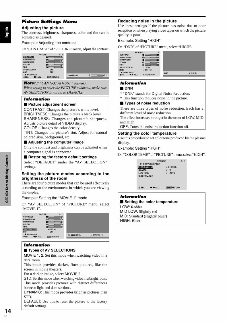
Picture Settings MenuAdjusting the pictureThe contrast, brightness, sharpness, color and tint can beadjusted as desired.
Example: Adjusting the contrast
On “CONTRAST” of “PICTURE” menu, adjust the contrast.PICTURE 1 / 2
CONTRASTBRIGHTNESSSHARPNESSCOLORTINTAV SELECTIONDNR NEXT PAGE
: STD: OFF
SEL. ADJ. EXIT RETURNCONTRAST 52
Note: If “CAN NOT ADJUST” appears ...When trying to enter the PICTURE submenu, make sureAV SELECTION is not set to DEFAULT.
Information� Picture adjustment screenCONTRAST: Changes the picture’s white level.BRIGHTNESS: Changes the picture’s black level.SHARPNESS: Changes the picture’s sharpness.Adjusts picture detail of VIDEO display.COLOR: Changes the color density.TINT: Changes the picture’s tint. Adjust for naturalcolored skin, background, etc.� Adjusting the computer imageOnly the contrast and brightness can be adjusted whena computer signal is connected.� Restoring the factory default settingsSelect “DEFAULT” under the “AV SELECTION”settings.
Setting the picture modes according to thebrightness of the roomThere are four picture modes that can be used effectivelyaccording to the environment in which you are viewingthe display.
Example: Setting the “MOVIE 1” mode
On “AV SELECTION” of “PICTURE” menu, select“MOVIE 1”.
PICTURE 1 / 2CONTRASTBRIGHTNESSSHARPNESSCOLORTINTAV SELECTIONDNR NEXT PAGE
: STD: OFF
SEL. ADJ. EXIT RETURNAV SELECTION : MOVIE 1
Information� Types of AV SELECTIONSMOVIE 1, 2: Set this mode when watching video in adark room.This mode provides darker, finer pictures, like thescreen in movie theaters.For a darker image, select MOVIE 2.STD: Set this mode when watching video in a bright room.This mode provides pictures with distinct differencesbetween light and dark sections.DYNAMIC: This mode provides brighter pictures thanSTD.DEFAULT: Use this to reset the picture to the factorydefault settings.
Reducing noise in the pictureUse these settings if the picture has noise due to poorreception or when playing video tapes on which the picturequality is poor.
Example: Setting “HIGH”
On “DNR” of “PICTURE” menu, select “HIGH”.PICTURE 1 / 2
CONTRASTBRIGHTNESSSHARPNESSCOLORTINTAV SELECTIONDNR NEXT PAGE
: STD: OFF
SEL. ADJ. EXIT RETURNDNR : HIGH
Information� DNR* “DNR” stands for Digital Noise Reduction.* This function reduces noise in the picture.� Types of noise reductionThere are three types of noise reduction. Each has adifferent level of noise reduction.The effect increases stronger in the order of LOW, MIDand High.OFF: Turns the noise reduction function off.
Setting the color temperatureUse this procedure to set color tone produced by the plasmadisplay.
Example: Setting “HIGH”
On “COLOR TEMP.” of “PICTURE” menu, select “HIGH”.
PICTURE 2 / 2 PREVIOUS PAGECOLOR TEMP.GAMMALOW TONEC.DETAIL ADJ.
: HIGH: 2: AUTO
SEL. ADJ. EXIT RETURN
Information� Setting the color temperatureLOW: RedderMID LOW: Slightly redMID: Standard (slightly bluer)HIGH: Bluer

Engl
ish
OSD
(On
Scre
en D
ispl
ay) C
ontr
ols
15En
Adjusting the color to the desired levelUse this procedure to adjust the white balance for eachcolor temperature to achieve the desired color quality.
Example: Adjusting the “R.HIGH” of “HIGH” colortemperature
Set “ADVANCED OSD” to “ON” in the main menu (1/2), then perform the following operations.
On “COLOR TEMP.” of “PICTURE” menu, select “HIGH”,then press the MENU/SET button.The “WHITE BALANCE” screen appears.On “R.HIGH”, adjust the white balance.
WHITE BALANCECOLOR TEMP. HIGH
R.HIGHG.HIGHB.HIGHR.LOWG.LOWB.LOWRESET : OFF
SEL. ADJ. EXIT RETURNR.HIGH 70
Information� Adjusting the white balanceR/G/B.HIGH: White balance adjustment for white levelR/G/B.LOW: White balance adjustment for black levelRESET: Resets settings to the factory default values.Use � and � buttons to select “ON”, then press theMENU/SET button.� Restoring the factory default settingsSelect “RESET” under the WHITE BALANCE menu.
Changing the Gamma CurveThis feature adjusts the brightness of the midtone areaswhile keeping shadows and highlights unchanged.
Example: Setting “3”
Set “ADVANCED OSD” to “ON” in the MAIN MENU(1/2), then perform the following operations.
On “GAMMA” of “PICTURE” menu, select “3”.
PICTURE 2 / 2 PREVIOUS PAGECOLOR TEMP.GAMMALOW TONEC.DETAIL ADJ.
: MID: 3: AUTO
SEL. ADJ. EXIT RETURN
Information� GAMMA settingsThe picture becomes darker as the number increases(in the sequence of 1, 2, 3, 4).
Making the Low Tone adjustmentsThis feature allows more detailed tone to be reproducedespecially in the dark area.
Example: Setting “2”
Set “ADVANCED OSD” to “ON” in the MAIN MENU(1/2), then perform the following operations.
On “LOW TONE” of “PICTURE” menu, select “2”.
PICTURE 2 / 2 PREVIOUS PAGECOLOR TEMP.GAMMALOW TONEC.DETAIL ADJ.
: MID: 2: 2
SEL. ADJ. EXIT RETURN
Information� LOW TONE settingsAUTO: Will automatically appraise the picture andmake adjustments.1: Will apply the dither method suitable for still pictures.2: Will apply the dither method suitable for motionpictures.3: Will apply the error diffusion method.
Adjusting the colorsUse this procedure to adjust hue and color density for red,green, blue, yellow, magenta and cyan.You can accentuate the green color of trees, the blue ofthe sky, etc.
Example: Adjusting the color detail adj for blue
Set “ADVANCED OSD” to “ON” in the MAIN MENU(1/2), then perform the following operations.
On “PICTURE” menu, select “C. DETAIL ADJ”, then pressthe MENU/SET button.The “C. DETAIL ADJ” screen appears.On “BLUE” of “C. DETAIL ADJ”, adjust the color detail.
C.DETAIL ADJREDGREENBLUEYELLOWMAGENTACYANRESET : OFF
SEL. ADJ. EXIT RETURN
M
G
R
B
C
Y
C
R
B
G
Y
M
Information� C. DETAIL ADJ settingsRED: Makes red’s adjustmentGREEN: Makes green’s adjustmentBLUE: Makes blue’s adjustmentYELLOW: Makes yellow’s adjustmentMAGENTA: Makes magenta’s adjustmentCYAN: Makes cyan’s adjustmentRESET: Resets settings to the factory default value.Use � and � buttons to select “ON”, then press theMENU/SET button.
Engl
ish
OSD
(On
Scre
en D
ispl
ay) C
ontr
ols
16En
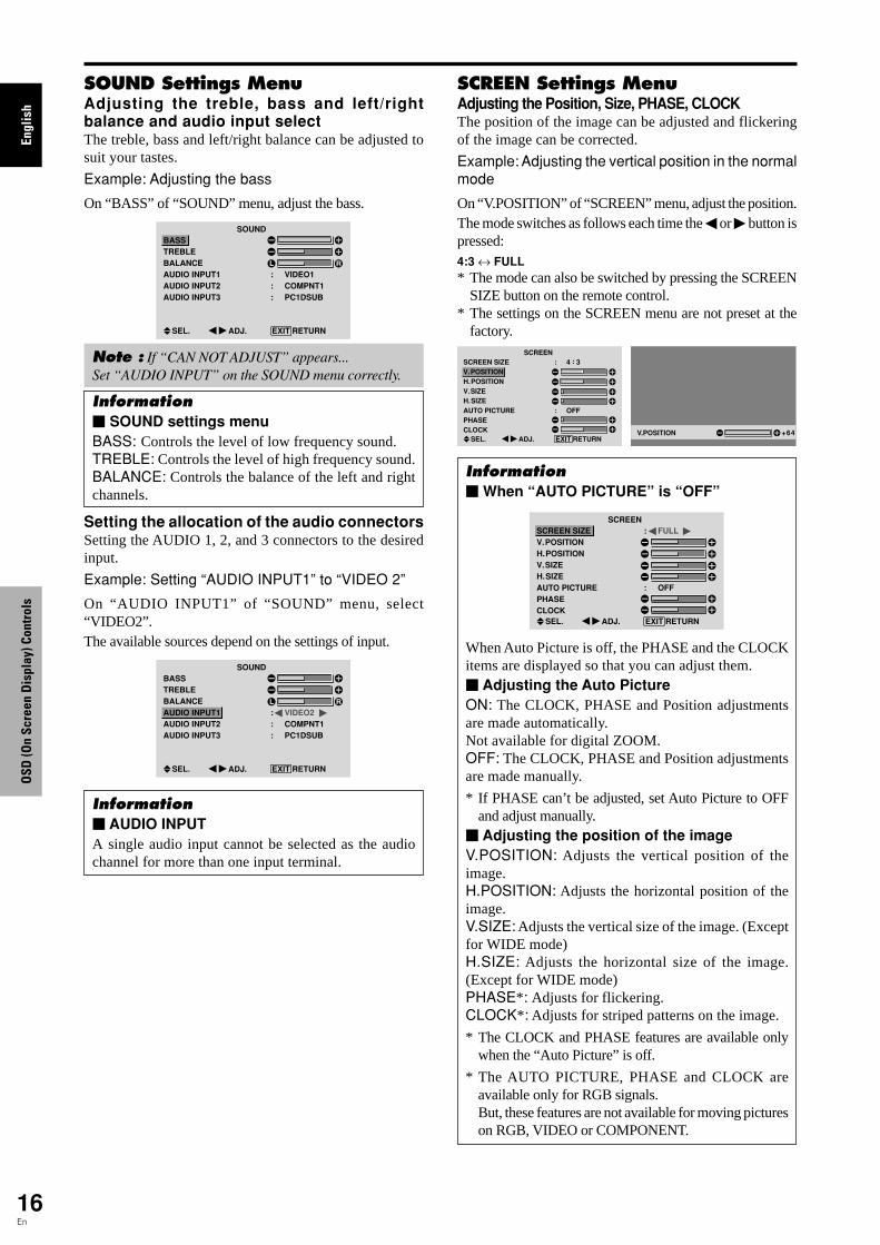
SOUND Settings MenuAdjusting the treble, bass and left/rightbalance and audio input selectThe treble, bass and left/right balance can be adjusted tosuit your tastes.
Example: Adjusting the bass
On “BASS” of “SOUND” menu, adjust the bass.
SOUNDBASSTREBLEBALANCEAUDIO INPUT1AUDIO INPUT2AUDIO INPUT3
: VIDEO1: COMPNT1: PC1DSUB
SEL. ADJ. EXIT RETURN
Note : If “CAN NOT ADJUST” appears...Set “AUDIO INPUT” on the SOUND menu correctly.
Information� SOUND settings menuBASS: Controls the level of low frequency sound.TREBLE: Controls the level of high frequency sound.BALANCE: Controls the balance of the left and rightchannels.
Setting the allocation of the audio connectorsSetting the AUDIO 1, 2, and 3 connectors to the desiredinput.
Example: Setting “AUDIO INPUT1” to “VIDEO 2”
On “AUDIO INPUT1” of “SOUND” menu, select“VIDEO2”.The available sources depend on the settings of input.
SOUNDBASSTREBLEBALANCEAUDIO INPUT1AUDIO INPUT2AUDIO INPUT3
: VIDEO2: COMPNT1: PC1DSUB
SEL. ADJ. EXIT RETURN
Information� AUDIO INPUTA single audio input cannot be selected as the audiochannel for more than one input terminal.
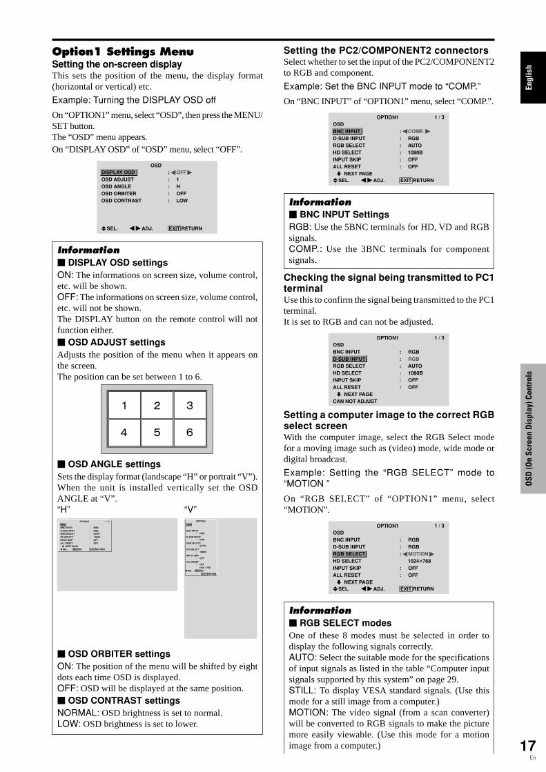
SCREEN Settings MenuAdjusting the Position, Size, PHASE, CLOCKThe position of the image can be adjusted and flickeringof the image can be corrected.
Example: Adjusting the vertical position in the normalmode
On “V.POSITION” of “SCREEN” menu, adjust the position.The mode switches as follows each time the � or � button ispressed:4:3 ↔ FULL* The mode can also be switched by pressing the SCREEN
SIZE button on the remote control.* The settings on the SCREEN menu are not preset at the
factory.SCREEN
SCREEN SIZEV.POSITIONH.POSITIONV.SIZEH.SIZEAUTO PICTUREPHASECLOCK
: 4 : 3
: OFF
SEL. ADJ. EXIT RETURNV.POSITION +64
Information� When “AUTO PICTURE” is “OFF”
SCREENSCREEN SIZEV.POSITIONH.POSITIONV.SIZEH.SIZEAUTO PICTUREPHASECLOCK
: FULL
: OFF
SEL. ADJ. EXIT RETURN
When Auto Picture is off, the PHASE and the CLOCKitems are displayed so that you can adjust them.� Adjusting the Auto PictureON: The CLOCK, PHASE and Position adjustmentsare made automatically.Not available for digital ZOOM.OFF: The CLOCK, PHASE and Position adjustmentsare made manually.
* If PHASE can’t be adjusted, set Auto Picture to OFFand adjust manually.
� Adjusting the position of the imageV.POSITION: Adjusts the vertical position of theimage.H.POSITION: Adjusts the horizontal position of theimage.V.SIZE: Adjusts the vertical size of the image. (Exceptfor WIDE mode)H.SIZE: Adjusts the horizontal size of the image.(Except for WIDE mode)PHASE*: Adjusts for flickering.CLOCK*: Adjusts for striped patterns on the image.
* The CLOCK and PHASE features are available onlywhen the “Auto Picture” is off.
* The AUTO PICTURE, PHASE and CLOCK areavailable only for RGB signals.But, these features are not available for moving pictureson RGB, VIDEO or COMPONENT.
Engl
ish
OSD
(On
Scre
en D
ispl
ay) C
ontr
ols
17En
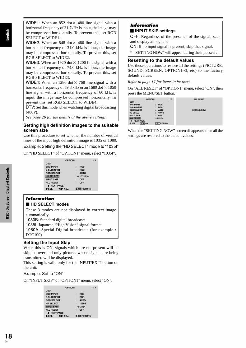
Option1 Settings MenuSetting the on-screen displayThis sets the position of the menu, the display format(horizontal or vertical) etc.
Example: Turning the DISPLAY OSD off
On “OPTION1” menu, select “OSD”, then press the MENU/SET button.The “OSD” menu appears.On “DISPLAY OSD” of “OSD” menu, select “OFF”.
OSDDISPLAY OSDOSD ADJUSTOSD ANGLEOSD ORBITEROSD CONTRAST
: OFF: 1: H: OFF: LOW
SEL. ADJ. EXIT RETURN
Information� DISPLAY OSD settingsON: The informations on screen size, volume control,etc. will be shown.OFF: The informations on screen size, volume control,etc. will not be shown.The DISPLAY button on the remote control will notfunction either.� OSD ADJUST settingsAdjusts the position of the menu when it appears onthe screen.The position can be set between 1 to 6.
� OSD ANGLE settingsSets the display format (landscape “H” or portrait “V”).When the unit is installed vertically set the OSDANGLE at “V”.“H” “V”
� OSD ORBITER settingsON: The position of the menu will be shifted by eightdots each time OSD is displayed.OFF: OSD will be displayed at the same position.� OSD CONTRAST settingsNORMAL: OSD brightness is set to normal.LOW: OSD brightness is set to lower.
Setting the PC2/COMPONENT2 connectorsSelect whether to set the input of the PC2/COMPONENT2to RGB and component.
Example: Set the BNC INPUT mode to “COMP.”
On “BNC INPUT” of “OPTION1” menu, select “COMP.”.
OPTION1 1 / 3OSDBNC INPUTD-SUB INPUTRGB SELECTHD SELECTINPUT SKIPALL RESET NEXT PAGE
: COMP.: RGB: AUTO: 1080B: OFF: OFF
SEL. ADJ. EXIT RETURN
Information� BNC INPUT SettingsRGB: Use the 5BNC terminals for HD, VD and RGBsignals.COMP.: Use the 3BNC terminals for componentsignals.
OPTION1 1 / 3OSDBNC INPUTD-SUB INPUTRGB SELECTHD SELECTINPUT SKIPALL RESET NEXT PAGE
: RGB: RGB: AUTO: 1080B: OFF: OFF
SEL. EXIT RETURNOKMENU
OPTION1OSD
BNC INPUT
D-SUB INPUT
RGB SELECT
HD SELECT
INPUT SKIP
ALL RESET
: RGB
: RGB
: AUTO
: 1080B
: OFF
: OFF 1024768
SEL.
EXIT RETURNOKMENU
Checking the signal being transmitted to PC1terminalUse this to confirm the signal being transmitted to the PC1terminal.It is set to RGB and can not be adjusted.
OPTION1 1 / 3OSDBNC INPUTD-SUB INPUTRGB SELECTHD SELECTINPUT SKIPALL RESET NEXT PAGECAN NOT ADJUST
: RGB: RGB: AUTO: 1080B: OFF: OFF
Setting a computer image to the correct RGBselect screenWith the computer image, select the RGB Select modefor a moving image such as (video) mode, wide mode ordigital broadcast.
Example: Setting the “RGB SELECT” mode to“MOTION ”
On “RGB SELECT” of “OPTION1” menu, select“MOTION”.
OPTION1 1 / 3OSDBNC INPUTD-SUB INPUTRGB SELECTHD SELECTINPUT SKIPALL RESET NEXT PAGE
: RGB: RGB: MOTION 1024×768: OFF: OFF
SEL. ADJ. EXIT RETURN
Information� RGB SELECT modesOne of these 8 modes must be selected in order todisplay the following signals correctly.AUTO: Select the suitable mode for the specificationsof input signals as listed in the table “Computer inputsignals supported by this system” on page 29.STILL: To display VESA standard signals. (Use thismode for a still image from a computer.)MOTION: The video signal (from a scan converter)will be converted to RGB signals to make the picturemore easily viewable. (Use this mode for a motionimage from a computer.)
Engl
ish
OSD
(On
Scre
en D
ispl
ay) C
ontr
ols
18En
Setting high definition images to the suitablescreen sizeUse this procedure to set whether the number of verticallines of the input high definition image is 1035 or 1080.
Example: Setting the “HD SELECT” mode to “1035I”
On “HD SELECT” of “OPTION1” menu, select “1035I”.
OPTION1 1 / 3OSDBNC INPUTD-SUB INPUTRGB SELECTHD SELECTINPUT SKIPALL RESET NEXT PAGE
: RGB: RGB: AUTO: 1035 I: OFF: OFF
SEL. ADJ. EXIT RETURN
Information� HD SELECT modesThese 3 modes are not displayed in correct imageautomatically.1080B: Standard digital broadcasts1035I: Japanese “High Vision” signal format1080A: Special Digital broadcasts (for example :DTC100)
Setting the Input SkipWhen this is ON, signals which are not present will beskipped over and only pictures whose signals are beingtransmitted will be displayed.This setting is valid only for the INPUT/EXIT button onthe unit.
Example: Set to “ON”
On “INPUT SKIP” of “OPTION1” menu, select “ON”.
OPTION1 1 / 3OSDBNC INPUTD-SUB INPUTRGB SELECTHD SELECTINPUT SKIPALL RESET NEXT PAGE
: RGB: RGB: AUTO: 1080B: ON: OFF
SEL. ADJ. EXIT RETURN
WIDE1: When an 852 dot� 480 line signal with ahorizontal frequency of 31.7kHz is input, the image maybe compressed horizontally. To prevent this, set RGBSELECT to WIDE1.WIDE2: When an 848 dot� 480 line signal with ahorizontal frequency of 31.0 kHz is input, the imagemay be compressed horizontally. To prevent this, setRGB SELECT to WIDE2.WIDE3: When an 1920 dot� 1200 line signal with ahorizontal frequency of 74.0 kHz is input, the imagemay be compressed horizontally. To prevent this, setRGB SELECT to WIDE3.WIDE4: When an 1280 dot� 768 line signal with ahorizontal frequency of 59.8 kHz or an 1680 dot� 1050line signal with a horizontal frequency of 60 kHz isinput, the image may be compressed horizontally. Toprevent this, set RGB SELECT to WIDE4.DTV: Set this mode when watching digital broadcasting(480P).See page 29 for the details of the above settings.
Resetting to the default valuesUse these operations to restore all the settings (PICTURE,SOUND, SCREEN, OPTION1~3, etc) to the factorydefault values.
Refer to page 12 for items to be reset.
On “ALL RESET” of “OPTION1” menu, select “ON”, thenpress the MENU/SET button.
OPTION1 1 / 3OSDBNC INPUTD-SUB INPUTRGB SELECTHD SELECTINPUT SKIPALL RESET NEXT PAGE
: RGB: RGB: AUTO: 1080B: OFF: ON
SEL. EXIT RETURNOKMENU
ALL RESET
SETTING NOW
When the “SETTING NOW” screen disappears, then all thesettings are restored to the default values.
Information� INPUT SKIP settingsOFF: Regardless of the presence of the signal, scanand display all signals.ON: If no input signal is present, skip that signal.
* “SETTING NOW” will appear during the input search.

Engl
ish
OSD
(On
Scre
en D
ispl
ay) C
ontr
ols
19En
Option2 Settings MenuSetting the power management for computerimagesThis energy-saving (power management) functionautomatically reduces the monitor’s power consumptionif no operation is performed for a certain amount of time.
Example: Turning the power management function on
Set “ADVANCED OSD” to “ON” in the main menu (1/2), then perform the following operations.
On “PWR. MGT.” of “OPTION2” menu, select “ON”.
OPTION2 2 / 3 PREVIOUS PAGEPWR. MGT.PURECINEMALONG LIFESIDE MASKS1/S2DVI SET-UP NEXT PAGE
: ON: ON
: 3: OFF
SEL. ADJ. EXIT RETURN
Information� Power management function* The power management function automatically reduces
the monitor’s power consumption if the computer’skeyboard or mouse is not operated for a certain amountof time. This function can be used when using themonitor with a computer.
* If the computer’s power is not turned on or if thecomputer and selector tuner are not properly connected,the system is set to the off state.
* For instructions on using the computer’s powermanagement function, refer to the computer’s operatinginstructions.
� Power management settingsON: In this mode the power management function isturned on.OFF: In this mode the power management function isturned off.� Power management function and STANDBY/ON indicatorThe STANDBY/ON indicator indicates the status ofthe power management function. See below forindicator status and description.
STANDBY/ON indicatorPowermanagementmode
On
Off
Turning the pictureback on
Picture already on.
Operate the keyboard ormouse. The picturereappears.
STANDBY/ON indicator
Green
Red
Powermanagementoperating status
Not activated.
Activated.
Description
Horizontal and verticalsynchronizing signalsare present from thecomputer.
Horizontal and/orvertical synchronizingsignals are not sentfrom the computer.
Setting the picture to suit the movieThe film image is automatically discriminated andprojected in an image mode suited to the picture.[NTSC, PAL, PAL60, 480I (60Hz), 525I (60Hz), 576I(50Hz), 625I (50Hz), 1035I (60Hz), 1080I (60Hz) only]
Example: Setting the “PURECINEMA” to “OFF”
Set “ADVANCED OSD” to “ON” in the main menu (1/2), then perform the following operations.
On “PURECINEMA” of “OPTION2” menu, select “OFF”.
OPTION2 2 / 3
: OFF: OFF
: 3: OFF
SEL. ADJ.
PREVIOUS PAGEPWR. MGT.PURECINEMALONG LIFESIDE MASKS1/S2DVI SET-UP NEXT PAGE
EXIT RETURN
Information� PURECINEMAON: Automatic discrimination of the image andprojection in PURECINEMA.OFF: PURECINEMA does not function.
Reducing burn-in of the screenThe brightness of the screen, the position of the picture,positive/negative mode and screen wiper are adjusted toreduce burn-in of the screen.Set “ADVANCED OSD” to “ON” in the main menu (1/2), then perform the following operations.
On “OPTION2” menu, select “LONG LIFE”, then press theMENU/SET button.The “LONG LIFE” screen appears.
LONG LIFEABLORBITERINVERSESCREEN WIPERSOFT FOCUS
: AUTO: OFF: OFF: OFF: OFF
SEL. ADJ. EXIT RETURN
ABL (Auto Brightness Limiter)
Use this to activate the brightness limiter.
Example: Setting “ABL” to “LOCK1”
On “ABL” of “LONG LIFE” menu, select “LOCK1”.
LONG LIFEABLORBITERINVERSESCREEN WIPERSOFT FOCUS
: LOCK1: OFF: OFF: OFF: OFF
SEL. ADJ. EXIT RETURN
Information� ABL settingsAUTO: The brightness of the screen is adjustedautomatically to suit the picture quality.LOCK1, 2, 3: Sets maximum brightness.The brightness level decreases in the order of LOCK 1,2, 3. LOCK 3 provides minimum brightness.

Engl
ish
OSD
(On
Scre
en D
ispl
ay) C
ontr
ols
20En
ORBITER
Use this to set the picture shift.
Example: Setting “ORBITER” to “AUTO1”
On “ORBITER” of “LONG LIFE” menu, select “AUTO1”.
LONG LIFEABLORBITERINVERSESCREEN WIPERSOFT FOCUS
: AUTO: AUTO1: OFF: OFF: OFF
SEL. ADJ. EXIT RETURN
Information� ORBITER settingsOFF: Orbiter mode does not function.This is the default setting when PC signal is input.AUTO1: The picture moves around the screenintermittently, making the picture smaller. This is thedefault setting when a Video or a COMPONENT signalis input. Set to “OFF” when these signals are not used.AUTO2: The picture moves around the screenintermittently, making the picture bigger.MANUAL: User can adjust the orbiter function(Horizontal Dot, Vertical Line and Time) manually.See the following explanation.
* When a Video or a COMPONENT signal is input, theAUTO1 and 2 functions will affect only the movingpicture and will not make the screen smaller or bigger.
Adjust the ORBITER function manually
Set the amount of shift and the time between movement.
Example: Setting so that the picture moves 2 dotshorizontally and 4 lines vertically every 3 minutes.
On “ORBITER” of “LONG LIFE” menu, select“MANUAL”, then press the MENU/SET button.THE “ORBITER” screen appears.Adjust the items.
ORBITERH-DOTV-LINETIME
: 2 DOT: 4 LINE: 3 M
SEL. ADJ. EXIT RETURN
Information� ORBITER Function settingsH-DOT: Moves from 1 to 20 dots in the horizontaldirection.V-LINE: Moves from 1 to 20 lines in the verticaldirection.TIME: Interval of 1~5 minutes (1 horizontal dot or 1vertical line per interval).
INVERSE
Use this to set the inverse mode or to display a whitescreen.
Example: Setting “INVERSE” to “WHITE”
On “INVERSE” of “LONG LIFE” menu, select “WHITE”.
LONG LIFEABLORBITERINVERSESCREEN WIPERSOFT FOCUS
: AUTO: OFF: WHITE: OFF: OFF
SEL. ADJ. EXIT RETURN
Information� INVERSE SettingsON: The picture is displayed alternately betweenpositive image and negative image.You can set the time by pressing the MENU/SET buttonwhile “ON” is set.OFF: Inverse mode does not function.WHITE: The entire screen turns white.You can set the time by pressing the MENU/SET buttonwhile “ON” is set.
Setting the time for INVERSE/WHITE
Set a time duration.
Example: Setting to that the INVERSE mode startsin 2 hours and proceeds for one hour and a half.
On “INVERSE” of “LONG LIFE” menu, select “ON”, thenpress the MENU/SET button.THE “INVERSE/WHITE” screen appears.Adjust the times.
INVERSE/WHITEWORKING TIMEWAITING TIME
: 01H30M: 02H00M
SEL. ADJ. EXIT RETURN
Information� Setting the timeWORKING TIME: Set the time duration for“INVERSE/WHITE”.When the WORKING TIME is set to “ON” the modewill stay on.WAITING TIME: Set the standby time until the“INVERSE/WHITE” mode starts.
* The “WAITING TIME” can not be set when the“WORKING TIME” is ON.
* THE “WORKING TIME” and “WAITING TIME” can beset for up to 12 hours and 45 minutes in units of 3 minutes.
* Ending a WORKING TIME function, the monitor willbe STAND BY.
[Example]WORKING TIME: 01H30MWAITING TIME: 02H00M
� To select “ON” for the “WORKING TIME”...Set the hours of the working time to 0H and the minutesto 0M. “ON” will be displayed.
←−−−− 2 H −−−−→←−− 1.5 H −−→←−−−−Start INVERSE/WHITE Start STAND BY

Engl
ish
OSD
(On
Scre
en D
ispl
ay) C
ontr
ols
21En
SCREEN WIPER
When this is set to ON, a white vertical bar movesrepeatedly from the left and of the screen to the right endat a constant speed.
Example: Setting “SCREEN WIPER” to “ON”
On “SCREEN WIPER” of “LONG LIFE” menu, select“ON”.
LONG LIFEABLORBITERINVERSESCREEN WIPERSOFT FOCUS
: AUTO: OFF: OFF: ON: OFF
SEL. ADJ. EXIT RETURN
Information� SCREEN WIPERON: The white vertical bar appears.You can set the time by pressing the MENU/SET buttonwhile “ON” is set.OFF: Screen wiper mode does not function.
Setting the time for SCREEN WIPER
Set a time duration and the speed.
Example: Setting so that the SCREEN WIPER modestarts in 30 minutes and proceeds for one and a halfhours.
On “SCREEN WIPER” of “LONG LIFE” menu, select“ON”, then press the MENU/SET button.THE “SCREEN WIPER” screen appears.Adjust the times and speed.
SCREEN WIPERWORKING TIMEWAITING TIMESPEED
: 01H30M: 00H30M: 3
SEL. ADJ. EXIT RETURN
Information� Setting the timeWORKING TIME: Set the time duration for “SCREENWIPER”.When the WORKING TIME is set to “ON” the modewill stay on.WAITING TIME: Set the standby time until the“SCREEN WIPER” mode starts.SPEED: Set the moving speed for the “SCREENWIPER”. The speed decreases as the number increases.
* The “WAITING TIME” can not be set when the“WORKING TIME” is ON.
* THE “WORKING TIME” and “WAITING TIME” canbe set for up to 12 hours and 45 minutes in units of 3minutes.
� To select “ON” for the “WORKING TIME”...Set the hours of the working time to 0H and the minutesto 0M. “ON” will be displayed.
SOFT FOCUS
Reduces edges and softens the image.
Example: Setting “SOFT FOCUS” to “2”
On “SOFT FOCUS” of “LONG LIFE” menu, select “2”.
LONG LIFEABLORBITERINVERSESCREEN WIPERSOFT FOCUS
: AUTO: OFF: OFF: OFF: 2
SEL. ADJ. EXIT RETURN
Information� SOFT FOCUS settingsOFF: Turns the SOFT FOCUS function off.1, 2, 3, 4: Activates the SOFT FOCUS setting. Thehigher numbers create a softer image.“SHARPNESS” can not be adjusted in the “PICTURE”menu.
Setting the gray level for the SIDE MASKUse this procedure to set the gray level for the parts on thescreen on which nothing is displayed when the screen isset to the 4:3 size or 14:9 size.
Example: Setting “SIDE MASK” to “5”
Set “ADVANCED OSD” to “ON” in the main menu (1/2), then perform the following operations.
On “SIDE MASK” of “OPTION2” menu, select “5”.
OPTION2 2 / 3
: OFF: ON
: 5: OFF
PREVIOUS PAGEPWR. MGT.PURECINEMALONG LIFESIDE MASKS1/S2DVI SET-UP NEXT PAGE
SEL. ADJ. EXIT RETURN
Information� SIDE MASK settingsThis adjusts the brightness of the black (the gray level)for the sides of the screen.The standard is 0 (black). The level can be adjustedfrom 0 to 15. The factory setting is 3 (dark gray).
Engl
ish
OSD
(On
Scre
en D
ispl
ay) C
ontr
ols
22En
Setting the screen size for S1/S2 video inputIf the S-video signal contains screen size information, theimage will be automatically adjusted to fit the screen whenthis S1/S2 is set to AUTO.This feature is available only when an S-video signal isinput via the VIDEO3 terminal.
Example: Setting “S1/S2” to “AUTO”
Set “ADVANCED OSD” to “ON” in the main menu (1/2), then perform the following operations.
On “S1/S2” of “OPTION2” menu, select “AUTO”.
OPTION2 2 / 3
: OFF: ON
: 3: AUTO
PREVIOUS PAGEPWR. MGT.PURECINEMALONG LIFESIDE MASKS1/S2DVI SET-UP NEXT PAGE
SEL. ADJ. EXIT RETURN
Information� S1/S2 settingsAUTO: Adjusts the screen size automatically accordingto the S1/S2 video signal.OFF: Turns the S1/S2 function off.
Setting the signal and black level for DVIsignalChoose the signal for the DVI connector (PC or STB/DVD) and set the black level.
Example: Setting the “PLUG/PLAY” mode to “STB/DVD”
Set “ADVANCED OSD” to “ON” in the main menu (1/2), then perform the following operations.
On “OPTION2” menu, select “DVI SET-UP”, then press theMENU/SET button.The “DVI SET-UP” screen appears.On “PLUG/PLAY” of “DVI SET-UP” menu, select “STB/DVD”.
DVI SET-UP: STB/DVD: HIGH
SEL. ADJ. EXIT RETURN
PLUG/PLAYBLACK LEVEL
Information� PLUG/PLAY settingsPC: When connected to the PC signal.BLACK LEVEL is set to “LOW” automatically.STB/DVD: When connected to the SET TOP BOX, DVD etc.BLACK LEVEL is set to “HIGH” automatically.� BLACK LEVEL settingsLOW: When connected to the PC signal.HIGH: When connected to the SET TOP BOX, DVD etc.Change “HIGH” into “LOW” if the black level appears gray.
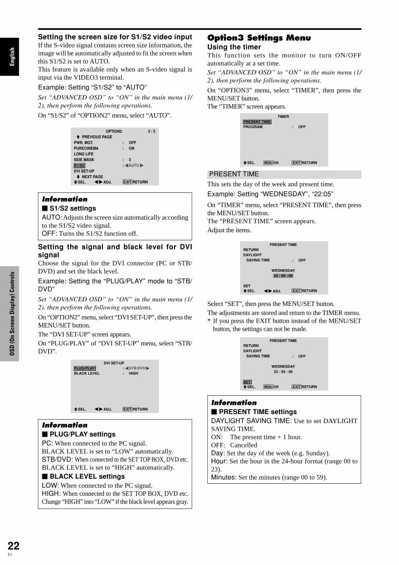
Option3 Settings MenuUsing the timerThis function sets the monitor to turn ON/OFFautomatically at a set time.Set “ADVANCED OSD” to “ON” in the main menu (1/2), then perform the following operations.
On “OPTION3” menu, select “TIMER”, then press theMENU/SET button.The “TIMER” screen appears.
TIMER
: OFF
SEL. EXIT RETURNOKMENU
PRESENT TIMEPROGRAM
PRESENT TIME
This sets the day of the week and present time.
Example: Setting “WEDNESDAY”, “22:05”
On “TIMER” menu, select “PRESENT TIME”, then pressthe MENU/SET button.The “PRESENT TIME” screen appears.Adjust the items.
SEL.
PRESENT TIME
WEDNESDAY22 : 05 : 00
RETURNDAYLIGHT SAVING TIME
SET
: OFF
ADJ. EXIT RETURN
Select “SET”, then press the MENU/SET button.The adjustments are stored and return to the TIMER menu.* If you press the EXIT button instead of the MENU/SET
button, the settings can not be made.
SEL.
PRESENT TIME
WEDNESDAY22 : 05 : 00
: OFF
RETURNDAYLIGHT SAVING TIME
SETEXIT RETURNOKMENU
Information� PRESENT TIME settingsDAYLIGHT SAVING TIME: Use to set DAYLIGHTSAVING TIME.ON: The present time + 1 hour.OFF: CancelledDay: Set the day of the week (e.g. Sunday).Hour: Set the hour in the 24-hour format (range 00 to23).Minutes: Set the minutes (range 00 to 59).
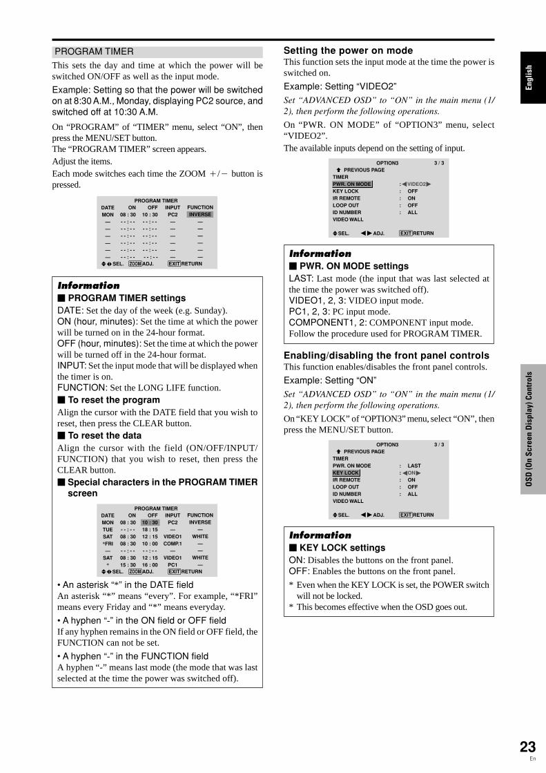
Engl
ish
OSD
(On
Scre
en D
ispl
ay) C
ontr
ols
23En
PROGRAM TIMER
This sets the day and time at which the power will beswitched ON/OFF as well as the input mode.
Example: Setting so that the power will be switchedon at 8:30 A.M., Monday, displaying PC2 source, andswitched off at 10:30 A.M.
On “PROGRAM” of “TIMER” menu, select “ON”, thenpress the MENU/SET button.The “PROGRAM TIMER” screen appears.Adjust the items.Each mode switches each time the ZOOM /� button ispressed.
PROGRAM TIMERDATEMON
——————
SEL.
ON08 : 30- - : - -
- - : - -
- - : - -
- - : - -
- - : - -
- - : - -
OFF10 : 30- - : - -
- - : - -
- - : - -
- - : - -
- - : - -
- - : - -
INPUTPC2——————
FUNCTIONINVERSE
——————
EXIT RETURNZOOM ADJ.
Information� PROGRAM TIMER settingsDATE: Set the day of the week (e.g. Sunday).ON (hour, minutes): Set the time at which the powerwill be turned on in the 24-hour format.OFF (hour, minutes): Set the time at which the powerwill be turned off in the 24-hour format.INPUT: Set the input mode that will be displayed whenthe timer is on.FUNCTION: Set the LONG LIFE function.� To reset the programAlign the cursor with the DATE field that you wish toreset, then press the CLEAR button.� To reset the dataAlign the cursor with the field (ON/OFF/INPUT/FUNCTION) that you wish to reset, then press theCLEAR button.� Special characters in the PROGRAM TIMER
screen
PROGRAM TIMERDATEMONTUESAT*FRI—
SAT*
SEL.
ON08 : 30- - : - -
08 : 3008 : 30- - : - -
08 : 3015 : 30
OFF10 : 3018 : 1512 : 1510 : 00- - : - -
12 : 1516 : 00
INPUTPC2—
VIDEO1COMP.1
—VIDEO1
PC1
FUNCTIONINVERSE
—WHITE
——
WHITE—
EXIT RETURNZOOM ADJ.
• An asterisk “*” in the DATE fieldAn asterisk “*” means “every”. For example, “*FRI”means every Friday and “*” means everyday.
• A hyphen “-” in the ON field or OFF fieldIf any hyphen remains in the ON field or OFF field, theFUNCTION can not be set.
• A hyphen “-” in the FUNCTION fieldA hyphen “-” means last mode (the mode that was lastselected at the time the power was switched off).
Setting the power on modeThis function sets the input mode at the time the power isswitched on.
Example: Setting “VIDEO2”
Set “ADVANCED OSD” to “ON” in the main menu (1/2), then perform the following operations.
On “PWR. ON MODE” of “OPTION3” menu, select“VIDEO2”.The available inputs depend on the setting of input.
OPTION3 3 / 3 PREVIOUS PAGETIMERPWR. ON MODEKEY LOCKIR REMOTELOOP OUTID NUMBERVIDEO WALL
: VIDEO2: OFF: ON: OFF: ALL
SEL. ADJ. EXIT RETURN
Information� PWR. ON MODE settingsLAST: Last mode (the input that was last selected atthe time the power was switched off).VIDEO1, 2, 3: VIDEO input mode.PC1, 2, 3: PC input mode.COMPONENT1, 2: COMPONENT input mode.Follow the procedure used for PROGRAM TIMER.
Enabling/disabling the front panel controlsThis function enables/disables the front panel controls.
Example: Setting “ON”
Set “ADVANCED OSD” to “ON” in the main menu (1/2), then perform the following operations.
On “KEY LOCK” of “OPTION3” menu, select “ON”, thenpress the MENU/SET button.
OPTION3 3 / 3 PREVIOUS PAGETIMERPWR. ON MODEKEY LOCKIR REMOTELOOP OUTID NUMBERVIDEO WALL
: LAST: ON: ON: OFF: ALL
SEL. ADJ. EXIT RETURN
Information� KEY LOCK settingsON: Disables the buttons on the front panel.OFF: Enables the buttons on the front panel.
* Even when the KEY LOCK is set, the POWER switchwill not be locked.
* This becomes effective when the OSD goes out.

Engl
ish
OSD
(On
Scre
en D
ispl
ay) C
ontr
ols
24En
Enabling/disabling remote control wirelesstransmissionThis function enables/disables remote control wirelesstransmission.
Example: Setting “OFF”
Set “ADVANCED OSD” to “ON” in the main menu (1/2), then perform the following operations.
On “IR REMOTE” of “OPTION3” menu, select “OFF”, thenpress the MENU/SET button.
OPTION3 3 / 3 PREVIOUS PAGETIMERPWR. ON MODEKEY LOCKIR REMOTELOOP OUTID NUMBERVIDEO WALL
: LAST: OFF: OFF: OFF: ALL
SEL. ADJ. EXIT RETURN
Information� IR REMOTE settingsON: Enables remote control wireless transmission.OFF: Disables remote control wireless transmission.Set “OFF” to avoid unwanted control from other remotecontrols.
Loop Out settingWhen this feature is set to ON, the received signal will belooped out.
Example: Setting “ON”
Set “ADVANCED OSD” to “ON” in the main menu (1/2), then perform the following operations.
On “LOOP OUT” of “OPTION3” menu, select “ON”.
OPTION3 3 / 3 PREVIOUS PAGETIMERPWR. ON MODEKEY LOCKIR REMOTELOOP OUTID NUMBERVIDEO WALL
: LAST: OFF: ON: ON: ALL
SEL. ADJ. EXIT RETURN
Information� LOOP OUT settingsON: The received signal will be looped out via PC1terminal or VIDEO1 terminal.OFF: The received signal will not loop out.
* Even if LOOP OUT is ON, signals won’t be sent out ifPOWER is being turned off.
� To connect another display...See page 3.� If the PC1 signal is present at the time the
power switched on...The PC1 input will be displayed regardless of the settingof LOOP OUT.
ID number settingWhen using more than one of these displays, this functionsets ID numbers so that operation of the remote controldoes not cause multiple monitors to operate at the sametime.
Example: Setting “2”
Set “ADVANCED OSD” to “ON” in the main menu (1/2), then perform the following operations.
On “ID NUMBER” of “OPTION3” menu, select “2”.
OPTION3 3 / 3 PREVIOUS PAGETIMERPWR. ON MODEKEY LOCKIR REMOTELOOP OUTID NUMBERVIDEO WALL
: LAST: OFF: ON: OFF: 2
SEL. ADJ. EXIT RETURN
* To reset back to ALLPress the CLEAR button.
Information� ID NUMBER settingsALL: ID NUMBER will not be set.1 to 256: ID NUMBER will be set.� When the ID NUMBER have been setYou can also set ID NUMBER for each remote controlto operate the plasma display individually. To do so,see below.
To set the ID number for the remote control
Example: Setting “2”
Press the ID NO. SET button on the remote control.The “ID NO. SET” screen appears.On “ID NUMBER” of “ID NO. SET” menu, select “2”.
ID NO.SETPOSITION : 1
: 2
ID NUMBER
ADJ. EXIT RETURN
* To reset back to ALLPress the CLEAR button.
Video Wall settingUse this feature to configure a 4-25 video wall.Set “ADVANCED OSD” to “ON” in the main menu (1/2), then perform the following operations.
On “OPTION3” menu, select “VIDEO WALL”, then pressthe MENU/SET button.The “VIDEO WALL” screen appears.
VIDEO WALLDIVIDERPOSITIONDISP. MODEAUTO IDSCREENP. ON DELAYABL LINKREPEAT TIMER
: 1
: NORMAL: OFF
: OFF: OFF: OFF
SEL. ADJ. EXIT RETURN
Note: A contingency method of shutting off the electricpower should be used in cases of emergency during videowall setup.
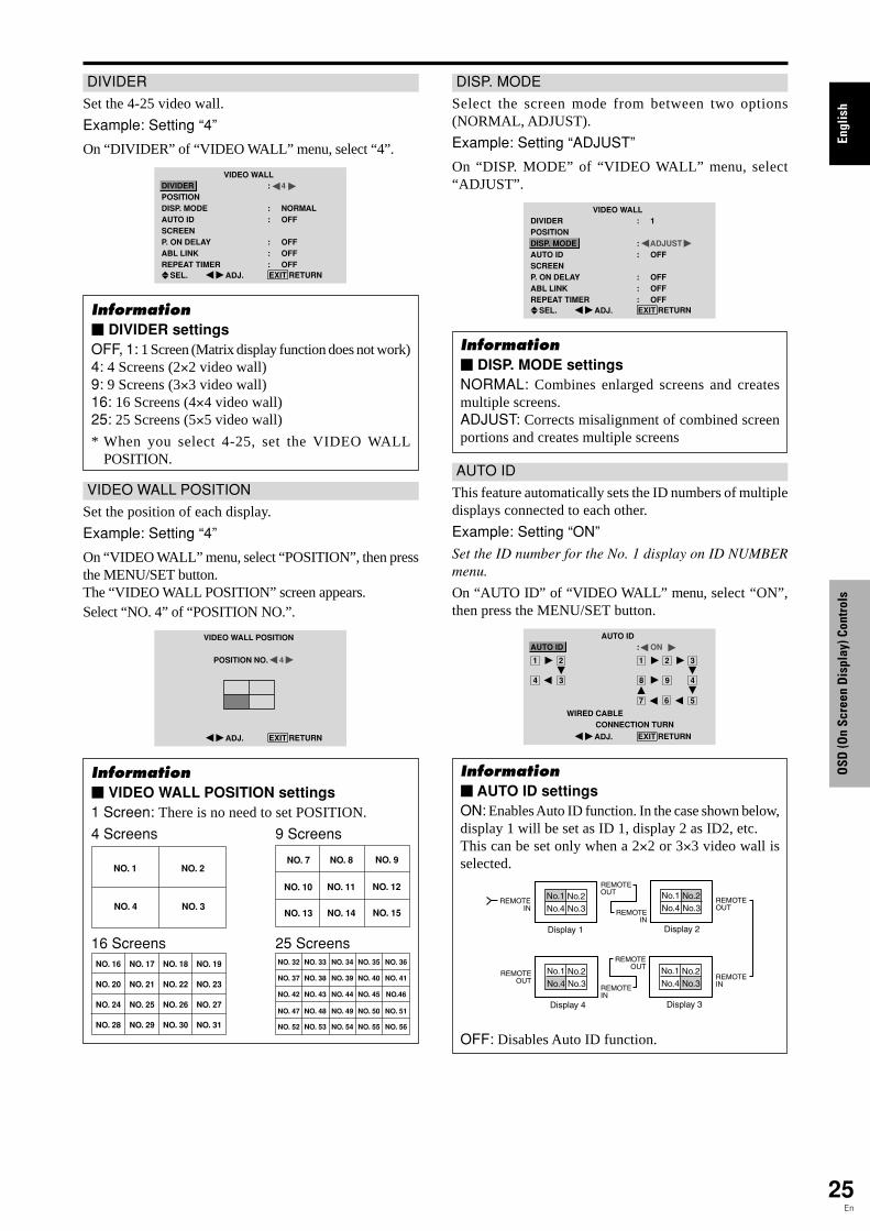
Engl
ish
OSD
(On
Scre
en D
ispl
ay) C
ontr
ols
25En
VIDEO WALL POSITION
Set the position of each display.
Example: Setting “4”
On “VIDEO WALL” menu, select “POSITION”, then pressthe MENU/SET button.The “VIDEO WALL POSITION” screen appears.Select “NO. 4” of “POSITION NO.”.
VIDEO WALL POSITION
POSITION NO. 4
ADJ. EXIT RETURN
Information� VIDEO WALL POSITION settings1 Screen: There is no need to set POSITION.
4 Screens 9 Screens
16 Screens 25 Screens
NO. 1 NO. 2
NO. 4 NO. 3
NO. 7 NO. 8 NO. 9
NO. 10 NO. 11 NO. 12
NO. 13 NO. 14 NO. 15
NO. 16 NO. 17 NO. 18 NO. 19
NO. 20 NO. 21 NO. 22 NO. 23
NO. 24 NO. 25 NO. 26 NO. 27
NO. 28 NO. 29 NO. 30 NO. 31
NO. 32 NO. 33 NO. 34 NO. 35 NO. 36
NO. 37 NO. 38 NO. 39 NO. 40 NO. 41
NO. 42 NO. 43 NO. 44 NO. 45 NO.46
NO. 47 NO. 48 NO. 49 NO. 50 NO. 51
NO. 52 NO. 53 NO. 54 NO. 55 NO. 56
DIVIDER
Set the 4-25 video wall.
Example: Setting “4”
On “DIVIDER” of “VIDEO WALL” menu, select “4”.
VIDEO WALLDIVIDERPOSITIONDISP. MODEAUTO IDSCREENP. ON DELAYABL LINKREPEAT TIMER
: 4
: NORMAL: OFF
: OFF: OFF: OFF
SEL. ADJ. EXIT RETURN
Information� DIVIDER settingsOFF, 1: 1 Screen (Matrix display function does not work)4: 4 Screens (2×2 video wall)9: 9 Screens (3×3 video wall)16: 16 Screens (4×4 video wall)25: 25 Screens (5×5 video wall)
* When you select 4-25, set the VIDEO WALLPOSITION.
AUTO ID
This feature automatically sets the ID numbers of multipledisplays connected to each other.
Example: Setting “ON”
Set the ID number for the No. 1 display on ID NUMBERmenu.
On “AUTO ID” of “VIDEO WALL” menu, select “ON”,then press the MENU/SET button.
AUTO ID: ON
1 2
4 3
1 2
8 9
3
4
6 57
WIRED CABLE CONNECTION TURN
ADJ. EXIT RETURN
AUTO ID
Information� AUTO ID settingsON: Enables Auto ID function. In the case shown below,display 1 will be set as ID 1, display 2 as ID2, etc.This can be set only when a 2×2 or 3×3 video wall isselected.
REMOTEIN
REMOTEIN
REMOTEOUT
REMOTEOUT
REMOTEIN
REMOTEOUT
REMOTEOUT
REMOTEIN
No.1 No.2No.3No.4
No.1 No.2No.3No.4
No.1 No.2No.3No.4
No.1 No.2No.3No.4
Display 1 Display 2
Display 4 Display 3
OFF: Disables Auto ID function.
DISP. MODE
Select the screen mode from between two options(NORMAL, ADJUST).
Example: Setting “ADJUST”
On “DISP. MODE” of “VIDEO WALL” menu, select“ADJUST”.
VIDEO WALLDIVIDERPOSITIONDISP. MODEAUTO IDSCREENP. ON DELAYABL LINKREPEAT TIMER
: 1
: ADJUST: OFF
: OFF: OFF: OFF
SEL. ADJ. EXIT RETURN
Information� DISP. MODE settingsNORMAL: Combines enlarged screens and createsmultiple screens.ADJUST: Corrects misalignment of combined screenportions and creates multiple screens

Engl
ish
OSD
(On
Scre
en D
ispl
ay) C
ontr
ols
26En
SCREEN
The position of the image can be adjusted and flickeringof the image can be corrected.
Example: Adjusting the vertical position
On “VIDEO WALL” menu, select “SCREEN”, then pressthe MENU/SET button.The “SCREEN” screen appears.On “V.POSITION” of “SCREEN” menu, adjust the position.
SCREENSCREEN SIZEV.POSITIONH.POSITIONV.SIZEH.SIZEAUTO PICTUREPHASECLOCK
: 4 : 3
: OFF
SEL. ADJ. EXIT RETURNV.POSITION +64
Information� SCREEN settingsThese are the same functions as the SCREEN menu onpage 16.
P. ON DELAY (Power on delay)
Use this function to activate power-on delay.Turn on the AUTO ID before the following operations.
Example: Setting “ON”
On “P. ON DELAY” of “VIDEO WALL” menu, select“ON”.
VIDEO WALLDIVIDERPOSITIONDISP. MODEAUTO IDSCREENP. ON DELAYABL LINKREPEAT TIMER
: 1
: NORMAL: OFF
: ON: OFF: OFF
SEL. ADJ. EXIT RETURN
Information� P. ON DELAY settingsON: Turns on the main power of each display after adelay time.OFF: Turns on the main power of all displays at thesame time.
(Only for 16 and 25 screens)MODE1: Turns on the main power of each displaydelayed.MODE2: Turns on the main power of each display moredelayed.
* Once this function has been set to “ON”, the POWERON/OFF button on the remote control does not functionexcept for the No.1 monitor.By pressing the POWER ON button on the remotecontrol the No.1 monitor will turn on and the otherswill be turned on one by one automatically.
* From the second monitor onward, neither the POWERbutton on the unit nor the POWER ON button on theremote control works. However, by pressing and holdingthe POWER ON button for more than 3 seconds, themonitor will be turned on.
ABL LINK
Use this function to set a uniform brightness for eachdisplay.Turn on the AUTO ID and set the DIVIDER (at 1, 4 or 9)before the following operations.
Example: Setting “ON”
On “ABL LINK” of “VIDEO WALL” menu, select “ON”,then press the MENU/SET button.
VIDEO WALLDIVIDERPOSITIONDISP. MODEAUTO IDSCREENP. ON DELAYABL LINKREPEAT TIMER
: 1
: NORMAL: OFF
: OFF: ON: OFF
SEL. ADJ. EXIT RETURN
Information� ABL LINK settingsON: Sets a uniform brightness for each screen in a videowall. This can be set only when a 2×2 or 3×3 videowall is selected.OFF: Sets the individual screen brightness for eachscreen in a video wall.
* When this function is set “ON”, connect your plasmadisplays with the remote cable (optional) in the order ofthe position numbers for the 2×2 video wall. See thedrawing below.
* If there are changes in the DIVIDER or POSITION,the ABL LINK will automatically turn OFF.
REMOTEIN
REMOTEIN
REMOTEOUT
REMOTEOUT
REMOTEIN
REMOTEOUT
REMOTEOUT
REMOTEIN
No.1 No.2No.3No.4
No.1 No.2No.3No.4
No.1 No.2No.3No.4
No.1 No.2No.3No.4
Display 1 Display 2
Display 4 Display 3
* With the 3×3 video wall, connect the final display tothe first display the same way as with 2×2 video wall.
Note: The remote control can be operated unless theIR REMOTE is set to “OFF”.

Engl
ish
OSD
(On
Scre
en D
ispl
ay) C
ontr
ols
27En
REPEAT TIMER
Use this to set two timers. Each timer can use theDIVIDER, SOURCE and WORK TIME functions.Turn on the AUTO ID and set the DIVIDER (at 1, 4 or 9)before the following operations.
Example:
TIMER1...VIDEO1 will be displayed for 3 minutes.TIMER2...PC1 will be displayed for 6 minutes in a
2×2 video wall.On “REPEAT TIMER” of “VIDEO WALL” menu, select“ON”, then press the MENU/SET button.The “REPEAT TIMER” screen appears.Adjust the items.
REPEAT TIMER: 1: VIDEO1: 00H03M
: 4: PC1DSUB: 00H06M
SEL. ADJ. EXIT RETURN
1 DIVIDER SOURCE WORK TIME 2 DIVIDER SOURCE WORK TIME
Information� REPEAT TIMER settingsDIVIDER: Divide the screen into 1, 4 or 9 sections.SOURCE: Set the input mode to be displayed.WORK TIME: Can be set to up to 4 hours 15 minutesin units of 1 minute.If you set both timers, Timer 1 and Timer 2 runconsecutively.In the case of the Video wall, timer No.1 can be used tocontrol all the displays simultaneously.
* This becomes effective when the OSD goes out.
Advanced OSD Settings MenuSetting the menu modeThis allows you to access full menu items.When P. ON DELAY or ABL LINK is ON, this won’t beturned OFF.
Example: Setting “ON”
On “ADVANCED OSD” of “MAIN MENU”, select “ON”.MAIN MENU 1 / 2
: OFF
SEL. ADJ. EXIT EXIT
PICTURESOUNDSCREENOPTION1
ADVANCED OSD NEXT PAGE
MAIN MENU 1 / 2
: ON
SEL. ADJ. EXIT EXIT
PICTURESOUNDSCREENOPTION1OPTION2OPTION3ADVANCED OSD NEXT PAGE
Information� ADVANCED OSD settingsON: All of the main menu items are available foradvanced users.OFF: Some of the main menu items are not available(e.g. OPTION2 and OPTION3).
Color System Settings MenuSetting the video signal formatUse these operations to set the color systems of compositevideo signals or Y/C input signals.
Example: Setting the color system to “3.58 NTSC”
On the MAIN MENU, select “COLOR SYSTEM”, then pressthe MENU/SET button.The “COLOR SYSTEM” screen appears.On “COLOR SYSTEM”, select “ 3.58NTSC ”.
COLOR SYSTEM
COLOR SYSTEM: 3.58NTSC
ADJ. EXIT RETURN
Information� Video signal formatsDifferent countries use different formats for videosignals. Set to the color system used in your currentcountry.AUTO: The color systems are automatically identifiedand the format is set accordingly.PAL: This is the standard format used mainly in theUnited Kingdom and Germany.SECAM: This is the standard format used mainly inFrance and Russia.4.43 NTSC, PAL60: This format is used for videos incountries using PAL and SECAM video signals.3.58 NTSC: This is the standard format used mainlyin the United States and Japan.PAL-M: This is the standard format used mainly inBrazil.PAL-N: This is the standard format used mainly inArgentina.
Source Information MenuChecking the frequencies, polarities of inputsignals, and resolutionUse this function to check the frequencies and polaritiesof the signals currently being input from a computer, etc.On “MAIN MENU”, select “SOURCE INFORMATION”,then press the MENU/SET button.The “SOURCE INFORMATION” is displayed.
SOURCE INFORMATION: 48.4kHz: 60.0Hz
: NEG.: NEG.
: 24: 1024×768EXIT RETURN
H. FREQUENCYV. FREQUENCY
H. POLARITYV. POLARITY
MEMORYRESOLUTION
PC: MEMORY will be displayed.Others: MODE will be displayed.
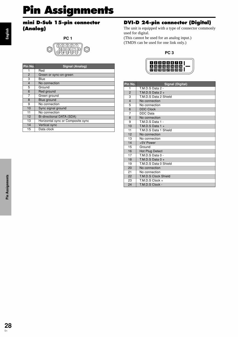
Engl
ish
28En
5 4 3 2 1
15 14 13 12 1110 9 8 7 6
PC 1
Signal (Analog)RedGreen or sync-on-greenBlueNo connectionGroundRed groundGreen groundBlue groundNo connectionSync signal groundNo connectionBi-directional DATA (SDA)Horizontal sync or Composite syncVertical syncData clock
Pin No.123456789
101112131415
1 2 3 4 5 6 7 89 10 11 12 13 14 15 16
20191817 21 22 23 24
PC 3
Pin No.123456789
101112131415161718192021222324
Signal (Digital)T.M.D.S Data 2 -T.M.D.S Data 2 +T.M.D.S Data 2 ShieldNo connectionNo connectionDDC ClockDDC DataNo connectionT.M.D.S Data 1 -T.M.D.S Data 1 +T.M.D.S Data 1 ShieldNo connectionNo connection+5V PowerGroundHot Plug DetectT.M.D.S Data 0 -T.M.D.S Data 0 +T.M.D.S Data 0 ShieldNo connectionNo connectionT.M.D.S Clock ShieldT.M.D.S Clock +T.M.D.S Clock -
mini D-Sub 15-pin connector(Analog)
DVI-D 24-pin connector (Digital)The unit is equipped with a type of connector commonlyused for digital.(This cannot be used for an analog input.)(TMDS can be used for one link only.)
Pin AssignmentsPi
n A
ssig
nmen
ts

Engl
ish
29En
Table of Signals Supported
Tabl
e of
Sig
nals
Sup
port
ed
Supported resolution• When the screen mode is NORMAL, each signal is converted to a 640 dots�480 lines signal. (Except for *2, *4)• When the screen mode is FULL, each signal is converted to a 853 dots�480 lines signal. (Except for *3)
Computer input signals supported by this system
Screen modeDots � lines
640�400640�480
848�480852�480*1
800�600
1024�768
1152�8641280�768
1280�768*9
1280�800*9
1280�854*9
1360�7651360�7681376�768
1280�1024
1680�1050*9
1600�1200
1920�1200*9
1920�1200RB*9
640�480832�624
1024�7681152�870
1440�900*9
1280�1024
1280�10241152�900
1280�10241024�768
1280�1024
768�576640�480
Verticalfrequency(Hz)
70.159.972.875.085.0
100.4120.460.060.056.360.372.275.085.199.8
120.060.070.175.085.0
100.675.056.259.869.860.060.060.060.059.960.075.085.0
100.160.060.065.070.075.085.060.060.066.774.674.975.160.060.071.272.066.076.076.160.060.0
50.059.9
Horizontalfrequency(kHz)
31.531.537.937.543.351.161.331.031.735.237.948.146.953.763.075.748.456.560.068.780.567.545.148.056.049.753.147.747.748.364.080.091.1
108.565.375.081.387.593.8
106.374.674.035.049.760.268.756.064.675.178.161.871.781.149.763.9
31.431.5
NORMAL(4:3)
YES*2*3
YES*3
YES*3
YES*3
YES*3
YES*3
YES*3
– –– –
YESYESYESYESYESYESYESYESYESYESYESYESYES– –– –– –– –– –– –– –– –
YES*4
YES*4
YES*4
YES*4
– –YESYESYESYESYES– –– –
YES*3
YESYESYES– –
YES*4
YES*4
YES*4
YESYES
YES*4
YESYES*4
YES*7
YES*7
FULL(16:9)YESYESYESYESYESYESYES
YES*3
YES*3
YESYESYESYESYESYESYESYESYESYESYESYESYESYESYESYESYESYESYESYESYESYESYESYESYESYESYESYESYESYESYESYESYESYESYESYESYESYESYESYESYESYESYESYESYESYES
YES*7
YES*7
RGBselect*5
– –STILL
– –STILL
– –– –– –
WIDE2WIDE1STILLSTILL
– –– –– –– –– –
STILL– –
STILL– –– –
STILLWIDE1WIDE3WIDE1WIDE1WIDE2WIDE1WIDE1WIDE2STILL
– –– –– –
WIDE4– –– –– –– –– –
WIDE2WIDE3
– –– –
WIDE1WIDE1
– –– –– –– –– –– –– –– –– –
– –MOTION
AppleMacintosh*6,
*8
Horizontal
NEGNEGNEGNEGNEGNEGNEGPOSNEGPOSPOSPOSPOSPOSPOSPOSNEGNEGPOSPOSNEGPOSPOSPOSNEGNEGNEGPOSPOSNEGPOSPOSPOSPOSNEGPOSPOSPOSPOSPOSNEGNEG
Sync on GSync on GSync on GSync on G
NEGNEGNEG– –
C SyncC SyncC Sync
– –– –
NEGNEG
Work Station(EWS4800)*8
Work Station (HP)*8
Work Station(SUN)*8
Work Station(SGI)IDC-3000G
Signal Type
IBM PC/ATcompatiblecomputers*8
Vertical
NEGNEGNEGNEGNEGNEGNEGPOSNEGPOSPOSPOSPOSPOSPOSPOSNEGNEGPOSPOSNEGPOSPOSNEGPOSNEGNEGPOSPOSPOSPOSPOSPOSPOSNEGPOSPOSPOSPOSPOSNEGNEG
Sync on GSync on GSync on GSync on G
NEGNEGNEG– –
C SyncC SyncC Sync
– –– –
NEGNEG
Sync Polarity PresenceHorizontal
YESYESYESYESYESYESYESYESYESYESYESYESYESYESYESYESYESYESYESYESYESYESYESYESYESYESYESYESYESYESYESYESYESYESYESYESYESYESYESYESYESYES– –– –– –– –
YESYESYES– –– –– –– –– –– –
YESYES
Vertical
YESYESYESYESYESYESYESYESYESYESYESYESYESYESYESYESYESYESYESYESYESYESYESYESYESYESYESYESYESYESYESYESYESYESYESYESYESYESYESYESYESYES– –– –– –– –
YESYESYES– –– –– –– –– –– –
YESYES
PAL625P
NTSC525P
Model DVI
NOYESYESYESYESYESYESYESYESYESYESYESYESYESYESYESYESYESYESYESYESYESNOYESYESYESYESNOYESYESYESYESYESNOYESYESNONONONO– –
YESNONONONOYESYESYESYESYESYESYESYESYES
NONO
Memory
45789
414219171112131415434424252627455152806621372222532930404738545556575881886
162839892948596061306229
3132
Engl
ish
30En
Tabl
e of
Sig
nals
Sup
port
ed
*1 Only when using a graphic accelerator board that is capable of displaying 852�480.*2 Display only 400 lines with the screen center of the vertical orientation located at the center.*3 The picture is displayed in the original resolution. The picture will be compressed for other signals.*4 Aspect ratio is 5:4. This signal is converted to a 600 dots�480 lines signal.*5 Normally the RGB select mode suite for the input signals is set automatically. If the picture is not displayed properly, set the
RGB mode prepared for the input signals listed in the table above.*6 To connect the monitor to Macintosh computer, use the monitor adapter (D-Sub 15-pin) to your computer's video port.*7 Other screen modes (ZOOM and WIDE) are available as well.*8 When viewing a moving picture at a vertical frequency greater than 65Hz, the picture may sometimes be unstable (jumpy).
If this occurs, please set the refresh rate of the external equipment to 60Hz.To view 480I@60Hz (480 interlaced lines, 60Hz refresh rate) or 576I@50Hz (576 interlaced lines, 50Hz refresh rate) whensync polarity is “Sync on Green”, set “RGB SELECT” to “MOTION”.
*9 CVT standard compliant.
NOTE:• While the input signals comply with the resolution listed in the table above, you may have to adjust the position and size of the
picture or the fine picture because of errors in synchronization of your computer.• This monitor has a resolution of 853 dots�480 lines. It is recommended that the input signal should be VGA, wide VGA, or
equivalent.• With digital input some signals are not accepted.• The sync may be disturbed when a nonstandard signal other than the aforementioned is input.• If you are connecting a composite sync signal, use the HD terminal.
What is HDCP/HDCP technology?HDCP is an acronym for High-bandwidth Digital Content Protection. High bandwidth Digital Content Protection (HDCP) is a systemfor preventing illegal copying of video data sent over a Digital Visual Interface (DVI).If you are unable to view material via the DVI input, this does not necessarily mean the PDP is not functioning properly. With theimplementation of HDCP, there may be cases in which certain content is protected with HDCP and might not be displayed due to thedecision/intention of the HDCP community (Digital Content Protection, LLC).
• “IBM PC/AT” and “VGA” are registered trademarks of International Business Machines, Inc. of the United States.• “Apple Macintosh” is a registered trademark of Apple Computer, Inc. of the United States.

Engl
ish
31En
Troubleshooting
Remedy• If there are no abnormalities in the image and sound,
the noise is caused by the cabinet reacting tochanges in temperature. This will not affectperformance.
• Leave some space between the display and theconnected components.
• Replace both batteries with new ones.
• Set IR REMOTE OFF on OPTION3 menu.
• Set an ID number with the ID NO. SET button, or setthe ID number to ALL.
• Plug the monitor’s power cord into a power outlet.
• Press the power button on the monitor to turn on thepower.
• Replace both batteries with new ones.
• Set IR REMOTE ON.
• Set an ID number with the ID NO. SET button, or setthe ID number to ALL.
• Point the remote control at the monitor’s remotecontrol sensor when pressing buttons, or remove theobstacle.
• Eliminate the light by closing curtains, pointing thelight in a different direction, etc.
• Replace both batteries with new ones.
• Unplug the remote cable from the monitor.
• Set the KEY Lock to OFF.
• Plug the monitor’s power cord into a power outlet.
• Increase the volume.
• Press the remote control’s MUTING button.
• Connect the speakers properly.
• Set AUDIO INPUT on the SOUND menu correctly.
• Adjust picture control as needed.Try another location for the monitor.Be sure all connections are secure.
• Adjust picture controls as needed.Check pin assignments and connections.
• Adjust the tint and color (under PICTURE).
• Turn on the computer’s power.
• Connect source to the monitor.
• Operate the computer (move the mouse, etc.).
• Set LOOP OUT OFF.
• Adjust the SCREEN properly.
• Press the SCREEN SIZE button on the remotecontrol and adjust properly.
• Set to the proper resolution.
• Check the input signal.
• Promptly switch off the power of the main unit andwait until the internal temperature drops. See*1.
• Prompty switch off the power of the main unit. See*2.
If the picture quality is poor or there is some other problem, check the adjustments, operations, etc., before requesting service.
SymptomThe unit emits a crackling sound.
Picture is disturbed.Sound is noisy.Remote control operates erroneously.
The remote control does not work.
Monitor’s power does not turn on when theremote control’s power button is pressed.
Monitor does not operate when the remotecontrol’s buttons are pressed.
The front panel buttons of the main unit donot function.
No sound or picture is produced.
Picture appears but no sound is produced.
Poor picture with VIDEO signal input.
Poor picture with RGB signal input.
Tint is poor or colors are weak.
Nothing appears on screen.
Part of picture is cut off or picture is notcentered.
Image is too large or too small.
Picture is unstable.
STANDBY/ON indicator is lighted in red.
STANDBY/ON indicator is blinking in red.
STANDBY/ON indicator is blinking in greenand red, or green.
Checks• Are the image and sound normal?
• Is a connected component set directly in front or atthe side of the display?
• Are the remote control’s batteries worn out?
• Is IR REMOTE set to ON?
• Has an ID number been set for the main unit?
• Is the monitor’s power cord plugged into a poweroutlet?
• Are all the monitor’s indicators off?
• Are the remote control’s batteries worn out?
• Is IR REMOTE set to OFF?
• Has an ID number been set for the main unit?
• Is the remote control pointed at the monitor, or isthere an obstacle between the remote control andthe monitor?
• Is direct sunlight or strong artificial light shining onthe monitor’s remote control sensor?
• Are the remote control’s batteries worn out?
• The remote cable is plugged into the REMOTE INterminal (Wired).
• The front panel buttons do not function during KEYLock.
• Is the monitor’s power cord plugged into a poweroutlet?
• Is the volume set at the minimum?
• Is the MUTING mode set?
• Are the speakers properly connected?
• Is AUDIO INPUT set correctly?
• Improper control setting.Local interference.Cable interconnections.Input impedance is not correct level.
• Improper control setting.Incorrect RGB connector pin connections.
• Are the tint and colors properly adjusted?
• Is the computer’s power turned on?
• Is a source connected?
• Is the power management function in the standbyor off mode?
• Is LOOP OUT set to ON?
• Is the position adjustment appropriate?
• Is the screen size adjustment appropriate?
• Is the computer’s resolution setting appropriate?
• Horizontal and / or vertical sync signal is notpresent when the Intelligent Power Managercontrol is on.
• The temperature inside the main unit has becometoo high and has activated the protector.
——————
*1 Overheat protectorIf the monitor becomes too hot, the overheat protector will be activated and the monitor will be turned off. If this happens, turn off the power to the monitorand unplug the power cord. If the room where the monitor is installed is particularly hot, move the monitor to a cooler location and wait for the monitorto cool for 60 minutes. If the problem persists, contact your dealer.
*2 In the following case, power off the monitor immediately and contact your dealer or authorized Service Center.The monitor turns off 5 seconds after powering on and then the STANDBY/ON indicator blinks. It indicates that the power supply circuit, plasma displaypanel or temperature sensor has been damaged.
Trou
bles
hoot
ing

Engl
ish
32En
SpecificationsScreen Size 36.3"(H)�20.4"(V) inches
921(H)�518(V) mmdiagonal 42"
Aspect Ratio 16 : 9
Resolution 853(H)�480(V) pixelsSignals
Synchronization Range Horizontal : 15.5 to 110 kHz(automatic : step scan)Vertical : 50.0 to 120 Hz(automatic : step scan)
Input Signals RGB, NTSC (3.58/4.43), PAL (B,G,M,N),PAL60, SECAM, HD*1 , DVD*1 , DTV*1
Input Terminals (VIDEO1 and PC1 can also be used as OUTPUT terminals)
PCVisual 1 (Analog) mini D-sub 15-pin�1Visual 2 (Analog) BNC (R, G, B, H/CS, V)�1*2
Visual 3 (Digital) DVI-D 24-pin�1*3
VideoVisual 1 BNC�1Visual 2 RCA-pin�1Visual 3 S-Video: DIN 4-pin�1
COMPONENTVisual 1 RCA-pin (Y, PB[CB], PR[CR])�1*1
Visual 2 BNC (Y, PB[CB], PR[CR])�1*1, *2
Audio Stereo RCA�3 (Selectable)
RS-232C D-sub 9-pin�1Sound output 8W+8W at 6 ohmPower Supply AC100-240V 50/60HzCurrent Rating 4.5A (maximum)
Power Consumption 270W (standby 0.9W)Dimensions 40 (W)�24 (H)�3.5 (D) inches
1018 (W)�610 (H)�89 (D) mm
Weight 62.8 lbs / 28.5 kg (without stand)Environmental Considerations
Operating Temperature 0°C to 40°C / 32°F to 104°FOther Features Motion compensated 3D Scan Converter (NTSC,
PAL, 480I, 576I, 525I, 625I, 1035I, 1080I), 2-3pull down Converter (NTSC, 480I, 525I, 1035I,1080I (60Hz)), 2-2 pull down Converter (PAL,576I, 625I, NTSC, 480I, 525I), Digital ZoomFunction (100-900% Selectable), Video Wall 4-25multi screen, Self Diagnosis, Image Burnreduction tools (ABL LOCK1~3, INVERSE,WHITE, ORBITER (Auto1,2/Manual), SCREENWIPER), Color Temperature select (high/mid/midlow/low, user has 4 memories), Key lock (Exceptpower SW), Auto Picture, Input Skip, ColorDetail Adjustment, Low Tone (3 mode), Auto ID,Programmable Timer, Gamma Correction(4 mode), Loop through interface, Plug and play(DDC1, DDC2b, PC3: DDC2b only)
Units are in mm(inch)
89
(3.5")
35(1.38") 54
(2.13")1018 (40")
610
(24"
)
Spec
ifica
tions
The features and specifications may be subject to change withoutnotice.
*1HD/DVD/DTV input signals supported on thissystem480P (60 Hz) 480I (60 Hz)525P (60 Hz) 525I (60 Hz)576P (50 Hz) 576I (50 Hz)625P (50 Hz) 625I (50 Hz)720P (60 Hz) 1035I (60 Hz)1080I (50 Hz) 1080I (60 Hz)
*2The 5-BNC connectors are used as PC2 andCOMPONENT2 input. Select one of them under“BNC INPUT”.
*3Compatable with HDCP.Supported Signals
• 640480P @ 59.94/60Hz • 19201080I @ 50Hz• 1280720P @ 59.94/60Hz • 720576P @ 50Hz• 19201080I @ 59.94/60Hz • 1440 (720)576I @ 50Hz• 720480P @ 59.94/60Hz• 1440 (720)480I @ 59.94/60HzNote: In some cases a signal on the plasma monitor may not be displayedproperly. The problem may be an inconsistency with standards fromthe source equipment (DVD, Set-top box, etc...). If you do experiencesuch a problem please contact your dealer and also the manufacturer ofthe source equipment.


![Pioneer 5g Pdp Plasma Tv Training Manual [ET]](https://static.fdocuments.in/doc/165x107/54ff9c444a79598f128b49a9/pioneer-5g-pdp-plasma-tv-training-manual-et.jpg)