PDMS DRAFT Administration Guide
133
PDMS DRAFT Administrator Application User Guide Version 11.6SP1 pdms1161/DRAFT Administration Guide issue 270605 www.cadfamily.com EMail:[email protected] The document is for study only,if tort to your rights,please inform us,we will delete
-
Upload
nkirubakarans -
Category
Documents
-
view
620 -
download
40
Transcript of PDMS DRAFT Administration Guide

PDMS DRAFT Administrator Application User Guide
Version 11.6SP1
pdms1161/DRAFT Administration Guide issue 270605 www.cadfamily.com EMail:[email protected]
The document is for study only,if tort to your rights,please inform us,we will delete

PLEASE NOTE:
AVEVA Solutions has a policy of continuing product development: therefore, the information contained in this document may be subject to change without notice. AVEVA SOLUTIONS MAKES NO WARRANTY OF ANY KIND WITH REGARD TO THIS DOCUMENT, INCLUDING BUT NOT LIMITED TO, THE IMPLIED WARRANTIES OF MERCHANTABILITY AND FITNESS FOR A PARTICULAR PURPOSE. While every effort has been made to verify the accuracy of this document, AVEVA Solutions shall not be liable for errors contained herein or direct, indirect, special, incidental or consequential damages in connection with the furnishing, performance or use of this material.
This manual provides documentation relating to products to which you may not have access or which may not be licensed to you. For further information on which Products are licensed to you please refer to your licence conditions.
© Copyright 1991 through 2005 AVEVA Solutions Limited All rights reserved. No part of this document may be reproduced, stored in a retrieval system or transmitted, in any form or by any means, electronic, mechanical, photocopying, recording or otherwise, without prior written permission of AVEVA Solutions. The software programs described in this document are confidential information and proprietary products of AVEVA Solutions or its licensors.
For details of AVEVA's worldwide sales and support offices, see our website at http://www.aveva.com
AVEVA Solutions Ltd, High Cross, Madingley Road, Cambridge CB3 0HB, UK www.cadfamily.com EMail:[email protected]
The document is for study only,if tort to your rights,please inform us,we will delete

Contents
1 About this Guide...........................................................................................1-1 1.1 The Scope of this Guide .............................................................................................1-1 1.2 How the Guide is Organised.......................................................................................1-1 1.3 Conventions Used in the Guide ..................................................................................1-2 2 Some General Principles..............................................................................2-1 2.1 The Role of the DRAFT Administrator ........................................................................2-1 2.2 Setting Up Administrative Access Rights....................................................................2-2 2.3 Supplied Libraries .......................................................................................................2-3 2.4 Searching Libraries.....................................................................................................2-3 2.5 The DRAFT Default Files............................................................................................2-3 3 Setting the DRAFT Defaults .........................................................................3-1 3.1 Setting the System Defaults .......................................................................................3-2 3.2 Saving and Loading Default Values............................................................................3-3 3.3 Setting Layer Purpose Definitions ..............................................................................3-4 3.4 Layer Creation Definitions ..........................................................................................3-6 3.5 Layer Purpose Filtering...............................................................................................3-6 3.6 Sheet Size Defaults ....................................................................................................3-7 3.7 Defining Element Naming Conventions ......................................................................3-8 3.8 Defining Pen Drawing Styles ......................................................................................3-9 3.9 Setting Plotting Options ............................................................................................3-12 3.10 ADP Administration...................................................................................................3-14 4 Selecting the Working Library .....................................................................4-1 4.1 Changing your Working Library ..................................................................................4-1 5 Sheet Library Administration.......................................................................5-1 5.1 Entering the Sheet Library Administration Application................................................5-1 5.2 Creating a Sheet Library.............................................................................................5-1 5.3 Creating a Backing Sheet and its Content..................................................................5-2 5.4 Creating an Overlay Sheet and its Content ................................................................5-4 6 Symbol Library Administration ...................................................................6-1 6.1 Entering Symbol Library Administration Mode............................................................6-1 6.2 Creating a Symbol Library ..........................................................................................6-1 6.3 Creating Symbol Templates .......................................................................................6-2 6.4 Adding Annotation via a Backing Sheet......................................................................6-3 7 ISODRAFT Symbol Library Administration ................................................7-1 7.1 Entering ISODRAFT Symbol Library Administration Mode ........................................7-1 7.2 Creating an ISODRAFT Symbol Library .....................................................................7-1 7.3 Creating ISODRAFT Symbol Templates ....................................................................7-2 7.4 Importing ISODRAFT Symbols...................................................................................7-2
VANTAGE PDMS DRAFT Administrator Application contents-i User Guide Version 11.6SP1 www.cadfamily.com EMail:[email protected]
The document is for study only,if tort to your rights,please inform us,we will delete

Contents
8 Label Library Administration .......................................................................8-1 8.1 Entering Label Library Administration Mode...............................................................8-1 8.2 Creating a Label Library .............................................................................................8-1 8.3 Creating Symbol Templates .......................................................................................8-2 8.4 Creating Text Templates ............................................................................................8-3 9 Style Library Administration........................................................................9-1 9.1 Creating a Style Library ..............................................................................................9-1 9.2 Creating and Deleting Styles ......................................................................................9-2 9.3 Setting Style Attributes ...............................................................................................9-3 9.4 Creating a Hatching Style Library ...............................................................................9-5 9.5 Creating and Deleting Hatching Styles .......................................................................9-5 9.6 Setting Hatching Style Attributes ................................................................................9-6 9.7 Creating Change Style Libraries.................................................................................9-7 9.8 Creating and Deleting Change Styles.........................................................................9-8 9.9 Setting Change Style Attributes..................................................................................9-9
9.9.1 Setting Change Design Style Attributes ......................................................................... 9-9 9.9.2 Setting Change Annotation Style Attributes ................................................................. 9-11
10 Representation Library Administration ....................................................10-1 10.1 Creating a Representation Library............................................................................10-1 10.2 Creating Representation Rule Sets ..........................................................................10-3 10.3 Creating and Deleting Representation Rules ...........................................................10-4 10.4 Associating Representation Rules with Styles..........................................................10-6 10.5 Creating Hatching Rule Sets ....................................................................................10-6 10.6 Creating and Deleting Hatching Rules......................................................................10-7 10.7 Associating Hatching Rules with Styles....................................................................10-9 10.8 Hatching Rule Attributes .........................................................................................10-10 10.9 Creating Change Rule Sets ....................................................................................10-12 10.10 Creating and Deleting Change Rules .....................................................................10-12 10.11 Associating Change Rules with Styles ...................................................................10-14 11 Drawlist Library Administration ................................................................11-1 11.1 Entering Drawlist Library Administration Mode.........................................................11-1 11.2 Creating a Drawlist Library .......................................................................................11-2 11.3 Creating Drawlists.....................................................................................................11-2 11.4 Defining Drawlist Members.......................................................................................11-4 12 Tag Rule Library Administration ...............................................................12-1 12.1 Entering Auto Tagging Administration Mode ............................................................12-1 12.2 Creating a Tag Rule Library......................................................................................12-1 12.3 Creating and Deleting Tag Rule Sets .......................................................................12-2 12.4 Creating and Setting Up Tag Rules ..........................................................................12-3 13 ADP Administration....................................................................................13-1 13.1 General ADP.............................................................................................................13-1
13.1.1 Setting the ADP Defaults.............................................................................................. 13-2 13.1.2 Creating a Tagging Library ........................................................................................... 13-4 13.1.3 Creating a Schedule Library ......................................................................................... 13-4 13.1.4 Backing Sheet Controls ................................................................................................ 13-7
13.2 Steelwork Detailing ADP...........................................................................................13-9 13.2.1 The SDA Options........................................................................................................ 13-10
Contents-ii VANTAGE PDMS DRAFT Administrator Application User Guide Version 11.6SP1 www.cadfamily.com EMail:[email protected]
The document is for study only,if tort to your rights,please inform us,we will delete

Contents
13.2.2 The SDA Customisation Macros ................................................................................ 13-10 13.3 Hangers and Supports ADP ...................................................................................13-11 14 AUTODRAFT Administration .....................................................................14-1 14.1 Accessing AUTODRAFT Administration...................................................................14-1 14.2 Starting the Symbol Editor ........................................................................................14-1 14.3 Starting the Frame Editor..........................................................................................14-3 14.4 Importing Symbols and Backing/Overlay Sheets......................................................14-4 15 Loading Data Files......................................................................................15-1 15.1 Accessing Load Data Files .......................................................................................15-1 16 Updating the Database...............................................................................16-1 16.1 Updating Picture Files...............................................................................................16-1 16.2 Updating Template Instancing ..................................................................................16-1 16.3 Updating Cross-DB Reference Attributes .................................................................16-2 16.4 Updating Cross-DB Name Attributes ........................................................................16-2 Appendix A The DRAFT Administrator Menus ...................................................... A-1
Appendix B The DRAFT Database Hierarchy ......................................................... B-1
Appendix C Libraries Supplied with DRAFT........................................................... C-1
Index
VANTAGE PDMS DRAFT Administrator Application Contents-iii User Guide Version 11.6SP1 www.cadfamily.com EMail:[email protected]
The document is for study only,if tort to your rights,please inform us,we will delete

Contents
Contents-iv VANTAGE PDMS DRAFT Administrator Application User Guide Version 11.6SP1 www.cadfamily.com EMail:[email protected]
The document is for study only,if tort to your rights,please inform us,we will delete

1 About this Guide
1.1 The Scope of this Guide
This document is intended for System Administrators responsible for setting up the Libraries used by the PDMS DRAFT applications. It is assumed that you are already familiar with using DRAFT to produce annotated drawings, and that you have attended a DRAFT Administration Training course. For information about training courses, see AVEVA's worldwide sales and support offices, see the Customer Support pages on our website at http://www.aveva.com/location For more information about using DRAFT, see the DRAFT online help and the VANTAGE PDMS DRAFT User Guide. Note: You must be a member of the DRAFTADMIN team in order to see
the Administration options on the DRAFT menus. See Section 2.2.
1.2 How the Guide is Organised
The remainder of this guide is made up of the following: • Chapter 2 explains some principles which you need to understand
before you try to use the DRAFT Administrator functions. • Chapter 3 explains how to control the default settings which affect
the way DRAFT’s applications appear to other users. • Chapter 4 tells you how to select the library you wish to work on. • Chapter 5 tells you how to configure a Sheet Library, giving users
access to standard backing sheets and/or overlay sheets. • Chapter 6 tells you how to configure a Symbol Library, from which
users can choose 2D symbols to add to their drawings. • Chapter 7 tells you how to configure an ISODRAFT Symbol Library,
where you can create symbols for use in ISODRAFT. • Chapter 8 tells you how to configure a Label Library, from which
users can choose symbolic and general labels.
VANTAGE PDMS DRAFT Administrator Application 1-1 User Guide Version 11.6SP1 www.cadfamily.com EMail:[email protected]
The document is for study only,if tort to your rights,please inform us,we will delete

About this Guide
• Chapter 9 tells you how to configure a Style Library (within the Representation Library), which controls the appearance of various aspects of the drawing (such as which parts of the model are drawn, and which pens are used for which types of line).
• Chapter 10 explains how to define Representation Rule Sets (within the Representation Library), which reference particular Styles. These can be used to link drawing styles to specific types of element within the Design DB if required.
• Chapter 11 tells you how to configure a Drawlist Library, which holds ID lists to control which elements are drawn.
• Chapter 12 explains how to set up the rules for automatic tagging of items in drawings
• Chapter 13 tells you how to set up defaults for Automatic Drawing Production.
• Chapter 14 tells you how to edit symbols and sheet frames for use within AUTODRAFT.
• Chapter 15 tells you how to use data files to create new projects. • Chapter 16 describes a special item on the Graphics menu which
allows you to update parts of the Draft DB explicitly, to correct inconsistencies which may arise due to operations in other PDMS modules such as reconfiguration.
• Appendix A shows, in a quick-reference format, the administration parts of the DRAFT menu hierarchy.
• Appendix B shows that part of the DRAFT (PADD) database hierarchy which is most relevant to the DRAFT administrator, namely the LIBY and its members. The full hierarchy is shown in the VANTAGE PDMS DRAFT User Guide.
• Appendix C shows the Library Hierarchy supplied with DRAFT.
1.3 Conventions Used in the Guide
Selections from bar menus, pull-down menus and submenus are shown using the > symbol. For example, the sequence Utilities > Reports > Run means ‘select Utilities from the bar menu, then select Reports from the resulting pull-down menu, then move the cursor to the right and select Run from the resulting submenu’.
1-2 VANTAGE PDMS DRAFT Administrator Application User Guide Version 11.6SP1 www.cadfamily.com EMail:[email protected]
The document is for study only,if tort to your rights,please inform us,we will delete

2 Some General Principles
This chapter explains some general principles, which you need to understand before you try to carry out any administrative functions in DRAFT. It explains: • Which aspects of DRAFT are under the control of the administrator. • What access rights you must have in the PDMS Project in order to be
able to act as a DRAFT administrator, and how to set these up.
2.1 The Role of the DRAFT Administrator
The DRAFT Administrator applications enable you to configure the DRAFT environment to suit specific company and/or project requirements in the following areas.
Default Settings The DRAFT defaults system allows you to define the following: • Library pointers • Layer settings • Sheet sizes • Naming conventions • User-definable pen settings • Name string delimiters The ways in which you set these up are explained in Chapter 4.
Libraries As DRAFT administrator, you are responsible for setting up the standard libraries that other users will reference during drawing production. You can create new libraries, or edit the content of existing libraries, so that the standard data available to individual DRAFT users complies with the company requirements for their particular drafting functions. The following types of library are controlled in this way: • Sheet libraries • Symbol libraries
VANTAGE PDMS DRAFT Administrator Application 2-1 User Guide Version 11.6SP1 www.cadfamily.com EMail:[email protected]
The document is for study only,if tort to your rights,please inform us,we will delete

Some General Principles
• ISODRAFT Symbol libraries • Label libraries • Style libraries • Representation rules libraries • Drawlist libraries • Auto Tagging rule libraries The ways in which you set these up are explained in Chapters 5 to 12.
Automatic Drawing Production The DRAFT Administration options allow you to set up defaults and define rules that control how drawings are automatically produced and annotated. These functions are explained in Chapter 13.
AutoDRAFT Symbols and Sheet Frames The DRAFT Administration options allow you to edit symbols and sheet frames for use with AutoDRAFT. You can also import symbols and sheet frames from AutoCAD work directories and macros. These functions are explained in Chapter 14
Creating Projects The Settings >Load data file option allows you to create new project areas using existing data files. This is explained fully in Chapter 15.
Database Updating Occasionally all or part of the DRAFT (PADD) DB may need to be updated to allow for changes made within PDMS but outside the normal DRAFT operations; typically when a project has been reconfigured or the Design DB has been rebuilt from macros. Updating the DRAFT database is explained in Chapter 16.
2.2 Setting Up Administrative Access Rights
In order to use the Administrator options on the DRAFT menus, you must enter PDMS as a User who is a member of the DRAFTADMIN team, and you must have Read/Write access to the DRAFT database that holds the libraries. The PDMS System Administrator should ensure that projects are set up in this way in PDMS ADMIN.
2-2 VANTAGE PDMS DRAFT Administrator Application User Guide Version 11.6SP1 www.cadfamily.com EMail:[email protected]
The document is for study only,if tort to your rights,please inform us,we will delete

Some General Principles
2.3 Supplied Libraries
The Sample Project supplied with the product contains two Departments, Master_Libraries and Project_Libraries. These Departments contain Libraries that contain sample sheets, symbols, and rulesets for tagging, representation etc. The contents of the sample Libraries are summarised in Appendix C.
2.4 Searching Libraries
When a DRAFT application user attempts to create a new element, for example, a symbolic label, the application searches for relevant Libraries in a specific sequence. It looks at each LIBY in the DEPT in the listed order until it finds one that contains appropriate type of Library. It then adds this LIBY and all subsequent LIBYs to the scrollable list on the Library form until it finds a LIBY which does not contain a relevant LALB. No further searching is carried out. This principle allows you, as the Administrator, to hide LIBYs from the user by adding them to the end of the DEPT’s members list. (You could, alternatively, store all reference LIBYs in a separate DEPT, but this would add extra DEPTs to the user’s Members List.) It is important to note that, due to this method of searching for the LIBYs, different types of Libraries must be grouped together under the same Department if they are all to be available to the user.
2.5 The DRAFT Default Files
The following is a summary of the default files supplied with the product. The files themselves contain additional information. The files are stored in the PDMSDFLTS directory. General Default Files
Name Description DRA-GEN-SYSTEM System defaults file DRA-GEN-SYSTEM.IMP System defaults file with imperial
settings DRA-GEN-SYSTEM.bak System defaults file back-up copy DRA-SETUP User configurable setup file
VANTAGE PDMS DRAFT Administrator Application 2-3 User Guide Version 11.6SP1 www.cadfamily.com EMail:[email protected]
The document is for study only,if tort to your rights,please inform us,we will delete

Some General Principles
DRA-GEN-LINDEF Macro executed on entry to DRAFT to define line pictures and patterns
DRA-GEN-FONTS Font names file: four font names can be defined
DRA-GEN-TEXT Sample intelligent texts displayed to user from dynamic text forms
DRA-GEN-CLASHTEMP Clash plotting macro template DRA-GEN-DEFLAY Layer setup macro: standard default DRA-GEN-DIMLAY Layer setup macro: dimension layers DRA-GEN-HLDLAY Layer setup macro: H&S layers DRA-GEN-LABLAY Layer setup macro: label layers DRA-GEN-MATLAY Layer setup macro: matchline layers DRA-GEN-NLLLAY Layer setup macro: label layers with no
leader lines DRA-GEN-NOTLAY Layer setup macro: note layers DRA-GEN-PLTEXT Projection-line text options DRA-GEN-RADLAY Layer setup macro: radial dimension
layers DRA-GEN-SYMLAY Layer setup macro: symbol layers (2D
SYMB) DRA-GEN-TAGLAY Layer setup macro: tagging layers
(layers with reserved purpose TAG) ADP Default Files
DRA-GENADP-EQUILOCN General ADP defaults file for equipment location plans
DRA-GENADP-PIPING General ADP defaults file for piping plan and elevation GAs
DRA-GENADP-PLOTPLAN General ADP defaults file for plot plans
DRA-GENADP-SUPPORTS General ADP defaults file for H&S drawings
DRA-ADP-BRANINLAY Layer setup macro for ADP branch labels
2-4 VANTAGE PDMS DRAFT Administrator Application User Guide Version 11.6SP1 www.cadfamily.com EMail:[email protected]
The document is for study only,if tort to your rights,please inform us,we will delete

Some General Principles
DRA-ADP-DIM1LAY Layer setup macro for ADP Type 1 dimensions
DRA-ADP-DIM2LAY Layer setup macro for ADP Type 2 dimensions
DRA-ADP-DIM3LAY Layer setup macro for ADP Type 3 dimensions
DRA-ADP-EQUICLLAY Layer setup macro for ADP equipment centrelines
DRA-ADP-PESYMBLAY Layer setup macro for ADP pipe end symbols
DRA-ADP-SCHEDLAY Layer setup macro for ADP schedules DRA-ADP-SCHEDSUPP Layer setup macro for ADP Hanger and
Support schedules DRA-ADP-TAGLAY Layer setup macro for ADP Tagging DRA-ADP-DIM3LEFTATTS
Dimension setup macro for ADP TYPE 3 dimensions LEFT side of view
DRA-ADP-DIM3UPATTS Dimension setup macro for ADP TYPE 3 dimensions UP side of view
DRA-SDADP-MACRO Macro file for setting defaults for Steelwork Detailing ADP.
H&S Default Files
DRA-SUPP Main H&S defaults DRA-SUPP-HADLAY Layer setup macro for hanger
dimension layers DRA-SUPP-HSMLAY Layer setup macro for hanger material
list layers DRA-SUPP-SIBLAY Layer setup macro for supported item
BOM layers DRA-SUPP-STBLAY Layer setup macro for steelwork BOM
layers
VANTAGE PDMS DRAFT Administrator Application 2-5 User Guide Version 11.6SP1 www.cadfamily.com EMail:[email protected]
The document is for study only,if tort to your rights,please inform us,we will delete

Some General Principles
Detail View Default Files DRA-LOC-LAYER Detail layer setup macro for master
view DRA-LOC-NOTE Default detail view note intelligent text
for master view DRA-LOC-NOTE-EXAMPLES
Examples of alternative detail view note intelligent texts for master view
DRA-DET-LAYER Detail layer setup macro for new detail view
DRA-DET-NOTE Default detail view note intelligent text for new detail view
DRA-DET-NOTE-EXAMPLES Examples of alternative detail view note intelligent texts for new detail view
Radial Dimension Default Files DRA-DIM-PDIM PDIM setup macro, this macro is
executed each time a PDIM is created DRA-DIM-RDIM RDIM setup macro, this macro is
executed each time a RDIM is created Miscellaneous Default Files
DRA-AUTONAME File required for successful appware loading (for future use)
2-6 VANTAGE PDMS DRAFT Administrator Application User Guide Version 11.6SP1 www.cadfamily.com EMail:[email protected]
The document is for study only,if tort to your rights,please inform us,we will delete

3 Setting the DRAFT Defaults
This chapter tells you how to define the default settings that will be used in the DRAFT applications. When you enter DRAFT and load the forms and menus interface, the macro %PDMSUI%/DRA/ADMIN/START calls the user-defined setup macro %PDMSDFLTS%/DRA-SETUP which, among other actions, points to the location of the main DRAFT defaults file, DRA-GEN-SYSTEM. The environment variable PDMSDFLTS is set to the directory where the defaults file is stored. Remember, if you wish to change the start up operation, that you should only modify DRA-SETUP, not the AVEVA-defined START or VARS files. As a DRAFT administrator, you can change the settings in the defaults files, if necessary creating a different defaults file for each of the company’s drafting requirements. The defaults file accessed by an individual user is determined by the setting of the user's PDMSDFLTS environment variable. Defaults can be set for the following: • Definitions of layers for use with views; defined in terms of their
purpose and associated attribute groups. • Definitions of name delimiters; that is, the characters used to
separate the component parts of an element’s name. • Pointers to the libraries from which the different aspects of DRAFT’s
drawing functions obtain their standard data, for example: 2D symbols and labels ◊
◊
◊
◊
◊
◊
◊
Backing sheets and overlay sheets Global representation rules and local styles Circulation lists Drawlists Tag rules and tag templates DRWG and SHEE templates
VANTAGE PDMS DRAFT Administrator Application 3-1 User Guide Version 11.6SP1 www.cadfamily.com EMail:[email protected]
The document is for study only,if tort to your rights,please inform us,we will delete

Setting the DRAFT Defaults
3.1 Setting the System Defaults
The DRAFT System Defaults form will be displayed when you select Settings > System Defaults from any of the DRAFT Administration main menus. The File gadget at the top of the body of the form shows the current defaults file. The Master Project Defaults and Local Project Defaults sections of the form show the default settings of the pointers to the DRAFT Libraries. If you want to change any of these, either type the new element name into the text box, or navigate to the element required and press the appropriate CE button. The text to the right of the CE button shows the type of element required for each Library. Note: The library reference defaults are also shown on a User Defaults
form that is accessed by selecting Options>Defaults from the main application menu. The User Defaults form is initialised with the settings from the Draft Defaults form after the defaults have been loaded from file. Subsequent changes made on the User Defaults form override (but do not change) the settings on the Draft Defaults form, allowing a user some flexibility in the use of available libraries during drawing production.
Name delimiters. By default, the individual parts of PDMS element names are separated by a slash delimiting character. For example: SHEETS/SHLB1/BACK1/SN1 This option allows you to specify any other delimiter character which has been used for Style names, Label Library names and Drawlist Library names.
The Further Defaults options are as follows:
Layer Purpose Definitions See Section 5.3. Layer Creation Definitions See Section 5.4. Layer Purpose Filtering See Section 5.5. Sheet Sizes See Section 5.6. Naming Conventions See Section 5.7. Pen Settings See Section 5.8.
The options under File on the menu at the top of the form are described in Section 5.2.
3-2 VANTAGE PDMS DRAFT Administrator Application User Guide Version 11.6SP1 www.cadfamily.com EMail:[email protected]
The document is for study only,if tort to your rights,please inform us,we will delete

Setting the DRAFT Defaults
3.2 Saving and Loading Default Values
Saving Default Files As supplied, the DRAFT applications reference a defaults file named DRA-GEN-SYSTEM that is set up to reference the AVEVA library database. When you have modified the defaults forms to suit your own requirements, you can save the updated settings to a file in the usual way; that is, either by updating the current file or by specifying a new file name. To do so, use the File>Save or File>Save As option, respectively, from the menu on the Draft System Defaults form. Loading Default Files You can load default settings from a file, which may be either the current defaults file or a different named file. To do so, use the File>Load or File>Load From option, respectively, from the menu on the Draft Defaults form. In each case, you can perform either a Full load or a Partial load by selecting the relevant option from the submenu. The difference is as follows: • Full loading of defaults:
Clears all existing default values from the forms before loading the new ones.
◊
◊
◊
◊
Checks that the minimum number of default values are loaded to allow the application to run correctly. This involves checking that all layer purposes are defined, that naming conventions are specified, and that sheet sizes are set. If any of these settings are not loaded from the specified file, the standard AVEVA values are loaded so that the application can still function.
• Partial loading of defaults: Does not clear existing form settings, allowing you to overwrite a subset of the total defaults available (which speeds up the process if only a few values are to be updated). Does not check the overall consistency of the loaded defaults (so a little care is needed to avoid problems).
Both full and partial loading modes keep a log of any errors that occur during loading and display these when loading has been completed. Each error message shows the load file line number at which the error occurred and a brief description of the error. To list the stored loading
VANTAGE PDMS DRAFT Administrator Application 3-3 User Guide Version 11.6SP1 www.cadfamily.com EMail:[email protected]
The document is for study only,if tort to your rights,please inform us,we will delete

Setting the DRAFT Defaults
errors at any time, select File > Display Errors from the menu on the Draft System Defaults form. Restoring Defaults from a Backup File Each time you save an updated defaults file the current defaults settings are saved in a backup file named DRA-GEN-SYSTEM.bak. To reload the previous default settings from the backup file, select File>Restore Backup from the menu on the Draft System Defaults form.
3.3 Setting Layer Purpose Definitions
The Layer Purpose Definitions form is displayed when you select the Layer Purpose Definitions button on the Draft System Defaults form.
Setup/Default filename,
executed when layer
is created
Delete selected
purpose definition
Purpose of layer
(must be 3 chars)
Attribute groups determine which attributes are
displayed on Layer Attributes form for this layer purpose
Accept current values
to update definition
The scrollable list shows all currently defined layer defaults. The highlighted layer is the one that will be updated by any new settings that you enter. All layers have a PURP attribute which is set to a four character keyword which identifies the purpose for which that layer is intended to be used. Layer purposes cannot be duplicated under any one owning View. The Layer Purpose box on the form allows you to specify the
3-4 VANTAGE PDMS DRAFT Administrator Application User Guide Version 11.6SP1 www.cadfamily.com EMail:[email protected]
The document is for study only,if tort to your rights,please inform us,we will delete

Setting the DRAFT Defaults
purpose as a three-character string (the fourth character is added automatically when setting PURP so that multiple layers of a given type can be created under a single View). For example, if you have defined a layer with its purpose defined as DIM and a user decides to have three dimension layers in each View for, say, steelwork (STLDIM), equipment (EQUDIM) and piping (PIPDIM), then the View contents might be as follows:
Element Type Name PURP
VIEW XYZ0001/S1/V1 n/a
LAYE XYZ0001/S1/V1/STLDIM DIMA
LAYE XYZ0001/S1/V1/EQUDIM DIMB
LAYE XYZ0001/S1/V1/PIPDIM DIMC
where the fourth character of the PURP (A, B or C) distinguishes the individual DIM layers. Note: The purpose keyword TAG is reserved for autotagging layers.
This is a requirement of the application (see Chapter 14) and must always be defined in the layer defaults. If it is omitted, a TAG layer purpose definition will be appended automatically during default initialisation. The TAG layer purpose definition cannot be deleted.
The Setup File box is used to specify the macro file that will be executed to set the layer attributes after a layer has been created. Default macro files are supplied with the product. For example, DRA-GEN-DEFLAY defines the default attribute values for layers. This ensures that all users create layer annotation to a common standard. You can copy and modify these macro files to meet your company and/or project standards. You can also create new files for other purpose types of your own definition. The Attribute Group buttons (Dim, Note, Text, Lab and Symb) allow you to specify which attribute types will be displayed on the Layer Attributes form. The combination which applies to each of the currently defined layers is shown by the + (selected) and - (unselected) codes in the scrollable list. To change these, toggle the buttons on and off as required and then click the Apply button.
VANTAGE PDMS DRAFT Administrator Application 3-5 User Guide Version 11.6SP1 www.cadfamily.com EMail:[email protected]
The document is for study only,if tort to your rights,please inform us,we will delete

Setting the DRAFT Defaults
3.4 Layer Creation Definitions
The Layer Creation Definitions form is displayed when you select the Layer Creation Definitions button on the Draft System Defaults form. This form allows you to define what layers are created, and how they are named, when a View is created.
Layer name
suffix
Purpose
Select the Purpose from the scrolling list, and change the Purpose and suffix as required. Note that you can create many layers with the same purpose.
3-6 VANTAGE PDMS DRAFT Administrator Application User Guide Version 11.6SP1
3.5 Layer Purpose Filtering
The Layer Purpose Filtering form is displayed when you select the Layer Purpose Filtering button on the Draft System Defaults form. This form defines what Layers are visible in the Layer Note option gadget on the appropriate application menu bar.
www.cadfamily.com EMail:[email protected] document is for study only,if tort to your rights,please inform us,we will delete

Setting the DRAFT Defaults
Option button shows Layers with PURP set to DIM, ADA, ADB, ADC
3.6 Sheet Size Defaults
The Sheet Defaults form is displayed when you select the Sheet Sizes button on the Draft System Defaults form. This form allows you to define the dimensions and a reference description for up to 15 standard sheet sizes:
VANTAGE PDMS DRAFT Administrator Application 3-7 User Guide Version 11.6SP1 www.cadfamily.com EMail:[email protected]
The document is for study only,if tort to your rights,please inform us,we will delete

Setting the DRAFT Defaults
3.7 Defining Element Naming Conventions
The Name Convention form is displayed when you select the Naming Conventions button on the Draft System Defaults form.
3-8 VANTAGE PDMS DRAFT Administrator Application User Guide Version 11.6SP1 www.cadfamily.com EMail:[email protected]
The document is for study only,if tort to your rights,please inform us,we will delete

Setting the DRAFT Defaults
Specifies whether or
not element is to
be named automatically
The form is divided into two parts: • Mandatory names, that is names for the elements which must be
named in order for the application to function correctly: DEPT, REGI, DRWG, SHEE and VIEW. For example, drawing numbers typically have a common project related prefix, which you should enter, in the Prefix box for the Drawing element.
• Optional names for the elements which do not need to be named for the application to function: VNOT, NOTE, RRUL and VSEC. For these elements, use the Named toggle button to specify whether or not automatic naming is required.
3.8 Defining Pen Drawing Styles
The Pen Settings form is displayed when you select the Settings > User Defined Pen Settings option on the DRAFT Administration main menu. DRAFT allows for the use of up to 255 numbered pens, allocated as follows: 1-120 Software-defined. These must not be changed, as the
application expects them to have their initial values. 121-130 Reserved for AutoDRAFT use. 131-170 User-definable within the DRAFT applications.
VANTAGE PDMS DRAFT Administrator Application 3-9 User Guide Version 11.6SP1 www.cadfamily.com EMail:[email protected]
The document is for study only,if tort to your rights,please inform us,we will delete

Setting the DRAFT Defaults
171-215 Unused. 216-255 Reserved for use by DRAFT applications. Note: In the DRAFT applications, pens 1-120 are selected by colour,
style and thickness rather than by number. The user–defined pens 131-170 are identified as pens 1-40 for ease of selection and it is these that we are concerned with here.
Device Plot PlotDevice
Prompts you to pick a pen from the Pens list
Lists available glyphs
Plus Star Ring Cross Stop
Normal Cross-Hatch Filled
Note: This form has intelligent settings, so that the parameters
available for selection are those relevant to the particular line style for the current pen.
The settings on all forms are referenced directly by the application, so any changes take effect immediately. DRAFT allows you to define two sets of pens: device pens and plot pens. For each pen number, there is a pen definition (style, colour, etc.) for both device and plot pens. You can either set these individually or simultaneously. To choose which pen type you wish to edit, use the Mode option button near the top of the form.
3-10 VANTAGE PDMS DRAFT Administrator Application User Guide Version 11.6SP1 www.cadfamily.com EMail:[email protected]
The document is for study only,if tort to your rights,please inform us,we will delete

Setting the DRAFT Defaults
Device Pens and Plot Pens To identify the pen whose settings you wish to edit, click the Select Pen button and then, when prompted, click on the required pen in the displayed Pens list. (You can position the cursor either on the pen number or on the sample line when picking a pen from the list.) The form settings will be updated automatically to show the attribute settings for the selected pen.
Selecting the Pen to be Defined You can set any of the standard DRAFT pen attributes for the currently selected pen by using the option buttons that make up the rest of the form:
Setting the Pen Properties Colour Sets the pen colour to one selected from a displayed list. Type The first button sets the drawing style to Solid, Dash, Dot,
Double or Chain. The second button sets any relevant subsidiary options. For example, if you select Solid, the only valid qualifier is Normal; if you select Dash, the qualifier may be Normal or Long.
Width Sets the line thickness index in the range 1 to 11. Increasing the index by 1 will increase the thickness by approximately 0.2 mm.
Glyph Sets a recurring glyph to one selected from a displayed list (unless set to None). With no glyph selected, the qualifying selections are invalid. With a glyph selected, relevant qualifiers may be set using the Line Gap, Spacing and Size option buttons. For example:
Glyph Spacing Line Gap (In this example, the glyph Size is the same as the Line
Gap.) Marker Sets the marker Symbol to Plus (+), Star (*), Ring (o), Cross
(x) or Stop (.) and the marker Scale in the range 1 to 8. The specified marker symbol is used to represent MRKP primitives.
Hatching The Type selection sets the hatching pattern to Normal, Cross–Hatch, or Filled:
VANTAGE PDMS DRAFT Administrator Application 3-11 User Guide Version 11.6SP1 www.cadfamily.com EMail:[email protected]
The document is for study only,if tort to your rights,please inform us,we will delete

Setting the DRAFT Defaults
The qualifying selections specify the Angle of the lines,
the Gap between lines, and whether each hatching line is single or double (Lines). The specified hatch pattern is used to fill closed primitives (CIRCs, RECTs, etc.).
3.9 Setting Plotting Options
DRAFT allows you to plot files in a variety of formats. As an Administrator you can enter or select operating system command strings that enable users to plot their files in a variety of formats. To select or enter output formats, select Settings>Plotting Options from the main DRAFT Administration menu. The Plotting Options form will appear.
This form contains four predefined command strings for PostScript and HPGL format conversion and printing. If you wish to use a conversion and printing procedure other than those given, replace the predefined entries by entering the procedure label into an Option label text box, and the appropriate operating system command string(s) into the corresponding System command string text box. The System command string has several components to it. For example: plotcadc FILE postscript \\printserver\psprint01
plotcadc is the name of the batch file PLOTCADC.BAT and uses
the parameters supplied in the rest of the system command string to specify the printing or other actions
3-12 VANTAGE PDMS DRAFT Administrator Application User Guide Version 11.6SP1 www.cadfamily.com EMail:[email protected]
The document is for study only,if tort to your rights,please inform us,we will delete

Setting the DRAFT Defaults
to be performed. This batch file uses the Plot Utility Program to perform the plot file conversions and the Windows print command to send them to a printer. This batch file is run when either of the Plot + File or Plot options are applied.
FILE A plot file is created when a drawing sheet is to be output. When the system command string is to be performed the location of this file plot file replaces the word ‘FILE’.
postscript This is the type of conversion from the PDMS plot file format to a compatible form the selected plotter. This file type for the plotter corresponds to a Plot Utility Program driver name; see the VANTAGE Plot User Guide for more details.
\\printserver\psprint01 This is the output string and in this example is the Windows network name of the destination printer.
Under the Windows O/S it is possible to set the System command string to direct the plot file directly to the default printer. This is made possible by utilising the AVEVA product called “Plot Viewer”.
PlotViewer /p FILE
Here, instead of the Plot program, the Plot Viewer program is executed with the following arguments.
/p run Plot Viewer in plot only mode and hence sends the plot file directly to the default printer.
FILE this word will be replaced by the plot file name Please note that the Plot Viewer program does not print at a true 100% scale, and therefore your print will be slightly smaller. An example of the modified form showing the PlotViewer entry is shown below.
VANTAGE PDMS DRAFT Administrator Application 3-13 User Guide Version 11.6SP1 www.cadfamily.com EMail:[email protected]
The document is for study only,if tort to your rights,please inform us,we will delete

Setting the DRAFT Defaults
Also available under the Windows O/S, it is possible to plot to any printer using the Screen pre-viewer. plotcadc FILE screen -0
Here, the Plot program is executed with the Screen argument. A pre-viewer form is shown which enable you to zoom in and out of the plot file. To send the plot file to a printer, press the button sequence Cntrl-P and the standard Windows print form will be displayed, allowing you to choose any printer as the destination. For more information on the subject of the Plot executable see the manual VANTAGE Plot User Guide. Once you have set all of the plotting options, select the one you require to be set as the default by clicking on the appropriate radio button in the Active column, then press OK. The Save>User options pull-down menu will save the settings, which can be recalled by selecting Load>User options. (Pressing OK also saves the settings before closing the form.) Load>Predefined options will load the predefined plotting settings.
3.10 ADP Administration
You set the defaults for Automatic Drawing Production from within the Auto Drawing Application. However, the Backing Sheets used for ADP Drawings must be created by the DRAFT Administrator. See Chapter 13 for details.
3-14 VANTAGE PDMS DRAFT Administrator Application User Guide Version 11.6SP1 www.cadfamily.com EMail:[email protected]
The document is for study only,if tort to your rights,please inform us,we will delete

4 Selecting the Working Library
When you enter one of the DRAFT Administration applications, you will be prompted to select a working library. Select Draft>Select Working Library. You will see the Library Selection form. The Type button at the top of the form allows you to select the type of library you wish to select (Sheet, Symbol, ISODRAFT Symbol or Label). After you have selected a type, you can scroll through the library list in the Main Library window until you find the main LIBY that holds the library you want to work with. After you have chosen a Main Library, all the libraries of the selected type held in the library will be displayed in the Main Library window on the right of the form. You can select the library you want from this window. Once you have selected your library, any related backing sheets or overlays are displayed in the bottom window of the form. You can select one of these if required.
4.1 Changing your Working Library
The icons at the top of your DRAFT display tell you: • The type and name of the library you have currently selected to work
on, for example:
• The library you have currently selected. For example:
All the libraries you have selected as working libraries in the current work session are shown in the option list. Clicking on any of the libraries in the list will automatically select that library and make it the current working library. Clicking the + button to the right of the list of working libraries adds the current element to the list, if it is a suitable type.
VANTAGE PDMS DRAFT Administrator Application 4-1 User Guide Version 11.6SP1 www.cadfamily.com EMail:[email protected]
The document is for study only,if tort to your rights,please inform us,we will delete

Selecting the Working Library
• The option gadget on the right allows you to switch the display of elements on and off. For example:
You can add existing Libraries to the list of Working Libraries by selecting Draft > Select Working Library. The Library Selection form will be displayed.
4-2 VANTAGE PDMS DRAFT Administrator Application User Guide Version 11.6SP1 www.cadfamily.com EMail:[email protected]
The document is for study only,if tort to your rights,please inform us,we will delete

5 Sheet Library Administration
This chapter tells you how to set up Sheet Libraries (SHLB) containing the Backing Sheets (BACK) and Overlay Sheets (OVER) that users can reference for use with their drawing sheets. The relevant hierarchy is shown in Appendix B. Note: The DEPT Project_Libraries, supplied as part of the standard
product, contains REGIs named /DRA/PRJ/TMP/discipline, where discipline is Piping, Equipment, etc. Each of these REGIs contains DRWGs, which own sample sheets with associated LIBYs. The DEPT Project_Libraries also contains a LIBY named DRA/PRJ/OVERS, which holds sample overlay sheets. The DEPT Master_Libraries contains a LIBY named DRA/MAS/BACKS, which holds sample backing-sheets.
5.1 Entering the Sheet Library Administration Application
From one of the DRAFT Administration menus, select Draft>Sheet Libraries. The main menu will change to the DRAFT Sheet Library Administration menu. The menu hierarchy is illustrated in Appendix A.2. All menu selections specified in the remainder of this chapter refer to this Sheet Library menu unless otherwise stated.
5.2 Creating a Sheet Library
To create a new SHLB, proceed as follows:
VANTAGE PDMS DRAFT Administrator Application 5-1 User Guide Version 11.6SP1 www.cadfamily.com EMail:[email protected]
The document is for study only,if tort to your rights,please inform us,we will delete

Sheet Library Administration
1. Navigate to the appropriate LIBY level in the existing hierarchy or, if necessary, use Create>Library to add a new LIBY.
2. Select Create>Sheet Library. It is recommended that you give the new SHLB a name that will make its content obvious to users.
3. The SHLB is effectively a drawing sheet template that aligns with the BACKs and OVERs that it owns, so you must specify its dimensions (either explicitly in the Width and Height boxes, or by selecting a standard sheet size using the option button). This size will be cascaded down to BACK and OVER level.
4. If you wish to define attributes at SHLB level, such that they will be cascaded down to BACK or OVER level, click on the Attributes button and change the settings on the Sheet Library form. (You can modify these attributes for individual BACKs or OVERs later if you wish.)
Standard sheet sizes Set attributes
See section 5.4
5.3 Creating a Backing Sheet and its Content
To create and display a new BACK, proceed as follows:
5-2 VANTAGE PDMS DRAFT Administrator Application User Guide Version 11.6SP1 www.cadfamily.com EMail:[email protected]
The document is for study only,if tort to your rights,please inform us,we will delete

Sheet Library Administration
1. Navigate to the appropriate SHLB level. 2. Select Create>Backing Sheet. It is recommended that you give the
new BACK a name that will make its content obvious to users. 3. The BACK is a drawing sheet on which you will position one or
more NOTEs, each of which may comprise any combination of 2D primitives, text primitives (TEXP) and existing symbol instances (SYMB).
Hint: You will find it easier to position and align individual NOTE components (i.e. primitives, text and/or symbol instances) if you display a working grid with a fairly small spacing (say 10 mm) and set the snap function to on.
4. For each NOTE in turn, select Create>Note>Back. 5. Depending on the detailed design required, create one or more
features of the Backing Sheet Note using the Create>2D Primitives, Create>2D Symbol and Create>Text options. As you create each feature, use the cursor to position it and, for a primitive, to define its size. If the grid snap function prevents you setting the precise position or size that you want, either turn snapping off temporarily or modify the attributes of the primitive later.
Restricting the Usable Area of a Sheet You can define the usable area of a sheet, so that the area in which a user can create views does not overlap any of the backing sheet annotation, by creating a special NOTE with the name backing_sheet_name/LIMITS. This NOTE should contain just a single RECT primitive that corresponds to the sheet area available to a user. When the user selects the option Create>View> Pre-defined Frame, DRAFT searches the sheet for this special note and, if found, the VIEW dimensions will be set automatically to fit into the RECT defining the available area. During creation of any Views the limits are used to set the initial position and size of the View, as shown:
VANTAGE PDMS DRAFT Administrator Application 5-3 User Guide Version 11.6SP1 www.cadfamily.com EMail:[email protected]
The document is for study only,if tort to your rights,please inform us,we will delete

Sheet Library Administration
Limits box
x
y
x/2
y/2
View
Sheet
5.4 Creating an Overlay Sheet and its Content
To create and display a new OVER, proceed as follows: 1. Navigate to the appropriate SHLB level. 2. Select Create>Overlay Sheet. It is recommended that you give the
new OVER a name to make its content obvious to users. This is important; as each drawing sheet is likely to reference several overlay sheets simultaneously. The function of the Ruleset Reference button will be explained in Step 4.
3. In its simplest form, the OVER is a drawing sheet on which you can position NOTEs, for which the procedure is exactly the same as for a BACK (see Section 9.3). However, an OVER can also own VIEWs, (typically used to display keyplan views of all or part of the Design DB), each of which can own one or more LAYERs, each of which can, in turn, own VNOTEs (View Notes). It is the VIEWs, and their members, which we will consider further (see the hierarchy in Appendix B).
Hint: You will find it easier to position and align individual VIEWs and their members if you display a working grid with a fairly small spacing (say 10 mm) and set the snap function to on.
4. To create a VIEW in an OVER, select Create>View>Limits Defined or Create>View>User Defined and set the VIEW attributes. Each VIEW can reference a Ruleset which defines the way in which its Design graphics are to be drawn: you can set the Ruleset Reference either
5-4 VANTAGE PDMS DRAFT Administrator Application User Guide Version 11.6SP1 www.cadfamily.com EMail:[email protected]
The document is for study only,if tort to your rights,please inform us,we will delete

Sheet Library Administration
at individual VIEW level, or at OVER level (see Step 2), or at SHLB level (Section 5.2).
Note: When you create a VIEW, a set of LAYERs is created automatically, their function and content being determined by the default settings, as explained in Section 4.3. (This is exactly the same as for the creation of VIEWs during the normal use of DRAFT.)
5. To create a VNOTE, navigate to the appropriate LAYER level and select Create>Note>Over.
6. Depending on the detailed design required, create one or more features of the View Note using the Draw options on the main menu. As you create each feature, use the cursor to position it and, for a primitive, to define its size. If the grid–snap function prevents you setting the precise position or size that you want, either turn snapping off temporarily or modify the attributes of the primitive later.
VANTAGE PDMS DRAFT Administrator Application 5-5 User Guide Version 11.6SP1 www.cadfamily.com EMail:[email protected]
The document is for study only,if tort to your rights,please inform us,we will delete

www.cadfamily.com EMail:[email protected] document is for study only,if tort to your rights,please inform us,we will delete

6 Symbol Library Administration
This chapter tells you how to set up Symbol Libraries (SYLB) containing the Symbol Templates (SYTM) from which users can select 2D symbols to add to their drawings. Each SYTM may comprise any combination of 2D primitives, text primitives (TEXP) and existing symbol instances (SYMB). The relevant hierarchy is shown in Appendix B. Note: The DEPT Master_Libraries, supplied as part of the standard
product, contains a REGI named DRA/MAS/SYMBOLS, which holds contains two LIBYs holding general symbols and electrical symbols, which you can adapt as required.
6.1 Entering Symbol Library Administration Mode
From one of the DRAFT Administration menus, select Draft>Symbol Libraries. The main menu will change to the DRAFT Symbol Library Administration menu. The menu hierarchy illustrated in Appendix A.3. All menu selections specified in the remainder of this chapter refer to the Symbol Library menu unless otherwise stated.
6.2 Creating a Symbol Library
To create a new SYLB, proceed as follows: 1. Navigate to the appropriate LIBY level in the existing hierarchy or,
if necessary, use Create>Library to add a new LIBY. 2. Select Create>Symbol Library. It is recommended that you give the
new SYLB a name that will make its content obvious to users. 3. The SYLB is effectively a drawing sheet on which you will position
the SYTMs, so you must specify its dimensions (either explicitly in the Width and Height boxes, or by selecting a standard sheet size using the option button).
4. If you wish to define attributes at SYLB level, such that they will be cascaded down to SYTM level, click on the Attributes... button and
VANTAGE PDMS DRAFT Administrator Application 6-1 User Guide Version 11.6SP1 www.cadfamily.com EMail:[email protected]
The document is for study only,if tort to your rights,please inform us,we will delete

Symbol Library Administration
change the relevant settings on the resulting form. (You can modify these attributes for individual SYTMs later if you wish.)
See Section 11.3
Standard sheet sizes Set attributes
6.3 Creating Symbol Templates
The SYTMs define the appearance of the 2D symbols which users can select and add to their drawings (as symbol instances). Hint: You will find it easier to position and align the individual parts of each SYTM (i.e. the primitives, text, and/or instances of other symbols) if you display a working grid with a fairly small spacing (say 10 mm) and set the snap function on. Create each SYTM as follows: 1. Select Create>Symbol Template and give the symbol a meaningful
name. 2. Use the cursor to position the origin of the SYTM at a convenient
grid point. 3. Depending on the detailed design required, create one or more
components of the SYTM in turn from the Draw options on the main menu bar. As you create each component, use the cursor to position
6-2 VANTAGE PDMS DRAFT Administrator Application User Guide Version 11.6SP1 www.cadfamily.com EMail:[email protected]
The document is for study only,if tort to your rights,please inform us,we will delete

Symbol Library Administration
it and, for a primitive, to define its size. If the grid–snap function prevents you setting the precise position or size that you want, either turn snapping off temporarily or modify the attributes of the primitive later. (Remember, when positioning the component parts of the SYTM, where you placed its origin in Step 2.)
6.4 Adding Annotation via a Backing Sheet
When you create each SYTM, you define its origin with respect to its component outlines. It is helpful if users can see where this origin is, but you may not want to make an origin marker part of the selectable symbol instance. Similarly, you may wish to add a descriptive name to the SYTM, as displayed on the SYLB sheet, in such a way that the name is not selected for display on the drawing sheet. The solution is to position the origin marker and descriptive name on a backing sheet that is displayed with, but does not form part of, the SYLB sheet. To do so, proceed as follows: 1. Examine the displayed SYLB sheet and make a note of the
coordinates of all locations at which you wish to position supplementary details. (You may be able to use the grid as a measuring scale if you have chosen a convenient spacing and have positioned SYTM components at grid intersection points.)
2. Change to Sheet Library Administration mode (see Chapter 5). Create a backing sheet (BACK) with the same dimensions as the SYLB sheet and display it in a 2D View.
3. For each required group of annotations on the SYLB, create a NOTE and position it at the appropriate point on the BACK (using the notes which you made in Step 1 as a reminder); or create all of the annotations within a single NOTE if you prefer.
4. Change back to Symbol Library Administration mode. Select Modify>Symbol Library>Definition and set the Backing Sheet Reference option to the name of the corresponding BACK that you have just created.
Now, when the SYLB is displayed, the annotation for each SYTM will be shown for the user’s guidance but will not be selected for adding to a drawing.
VANTAGE PDMS DRAFT Administrator Application 6-3 User Guide Version 11.6SP1 www.cadfamily.com EMail:[email protected]
The document is for study only,if tort to your rights,please inform us,we will delete

Symbol Library Administration
6-4 VANTAGE PDMS DRAFT Administrator Application User Guide Version 11.6SP1 www.cadfamily.com EMail:[email protected]
The document is for study only,if tort to your rights,please inform us,we will delete

7 ISODRAFT Symbol Library Administration
This chapter tells you how to set up ISODRAFT Symbol Libraries (ISOLB), containing ISODRAFT Symbol Templates (ISOTM). This allows you create and modify ISODRAFT Symbol Keys.
7.1 Entering ISODRAFT Symbol Library Administration Mode
From one of the DRAFT Administration Applications main menus, select Draft>ISODRAFT Symbol Libraries. The main menu will change to the ISODRAFT Symbol Library Administration menu. The menu hierarchy is illustrated in Appendix B. All menu selections specified in the remainder of this chapter refer to the ISODRAFT Symbol Library menu unless otherwise stated.
7.2 Creating an ISODRAFT Symbol Library
To create a new ISODRAFT Symbol Library (ISOLB): 1. Navigate to the appropriate LIBY level in the existing hierarchy or,
if necessary, use Create>Library to add a new LIBY. 2. Select Create>ISODRAFT Symbol Library. It is recommended that you
give the new ISOLB a name that will make its content obvious to users.
3. The ISOLB is a drawing sheet on which you will position the ISOTMs, so you must specify its dimensions (either explicitly in the Width and Height boxes, or by selecting a standard sheet size using the option button).
4. If you wish to define attributes at ISOLB level, such that they will be cascaded down to ISOTM level, click on the Attributes... button and change the relevant settings on the resulting form. (You can modify these attributes for individual ISOTMs later if you wish.)
VANTAGE PDMS DRAFT Administrator Application 7-1 User Guide Version 11.6SP1 www.cadfamily.com EMail:[email protected]
The document is for study only,if tort to your rights,please inform us,we will delete

ISODRAFT Symbol Library Administration
7.3 Creating ISODRAFT Symbol Templates
The ISODRAFT Symbol Templates allow ISODRAFT users to produce user-defined symbols using the DRAFT interface. The symbol definition is made up of two components - straights and markers. Straights can be solid for normal lines, dashed for insulation lines and chained for tracing lines. Markers can be defined for symbol arrive and leave points, tee points and spindle points. Create each ISOTM as follows: 1. Select Create>ISODRAFT Symbol Template and give the symbol a
name. 2. The Symbol Template Form will be displayed. For more information,
see the online help. 3. Define the symbol geometry using the pending on the detailed
design required, create one or more components of the ISOTM in turn from the Draw, Construct, and Edit options, which are used in the same way as in the 2D Drafting Application.
You can add annotation to an ISODRAFT Symbol Template in the same way as for Symbol Templates. 4. Export the ISODRAFT Symbol by selecting Utilities > Export
ISODRAFT Symbol. See the online help for more information.
7.4 Importing ISODRAFT Symbols
The Import Isodraft Symbols form is displayed when you select Utilities > Import Isodraft Symbols from the ISODRAFT Symbol Library Administration menu. The form allows you to import ISODRAFT symbol macro files into DRAFT symbol libraries. You specify the filename of the file containing ISODRAFT symbol macros, and give the name of symbol library. The Apply button imports the given symbol macro file into the DRAFT symbol library. The first symbol is positioned at the bottom left hand corner of the Sheet. Subsequent symbols are tabulated across and up the page. When there is no space left on the Sheet, a new ISOLB is created. For more information, see the on-line help for the Import Isodraft Symbols form.
7-2 VANTAGE PDMS DRAFT Administrator Application User Guide Version 11.6SP1 www.cadfamily.com EMail:[email protected]
The document is for study only,if tort to your rights,please inform us,we will delete

8 Label Library Administration
This chapter tells you how to set up Label Libraries (LALB) containing the Symbol Templates (SYTM) and Text Templates (TXTM) from which users can create symbolic (SLAB) or general (GLAB) labels, respectively. Each SYTM may comprise any combination of 2D primitives, text primitives (TEXP) and existing symbol instances (SYMB). Each TXTM holds specific or intelligent (i.e. #-coded) text in its BTEX attribute. The relevant hierarchy is shown in Appendix B. NOTE: The DEPT Master_Libraries, supplied as part of the standard
product, contains a REGI named DRA/MAS/LABELS, which holds contains LIBYs holding different types of label templates, which you can adapt as required.
8.1 Entering Label Library Administration Mode
From one of the DRAFT Administration Application main menus, select Draft>Label Libraries. The main menu will change to the Label Library Administration menu, which gives you access to the menu hierarchy illustrated in Appendix A.5. All menu selections specified in the remainder of this chapter refer to this Label Library menu unless otherwise stated.
8.2 Creating a Label Library
To create a new LALB, proceed as follows: 1. Navigate to the appropriate LIBY level in the existing hierarchy or,
if necessary, use Create>Library to add a new LIBY. 2. Select Create>Label Library. It is recommended that you give the new
LALB a name that will make its content obvious to users. 3. The LALB is effectively a drawing sheet on which you will position
the SYTMs and TXTMs, so you must specify its dimensions (either explicitly in the Width and Height boxes, or by selecting a standard sheet size using the option button).
VANTAGE PDMS DRAFT Administrator Application 8-1 User Guide Version 11.6SP1 www.cadfamily.com EMail:[email protected]
The document is for study only,if tort to your rights,please inform us,we will delete
Label Library Administration
4. If you wish to define attributes at LALB level, such that they will be cascaded down to SYTM and TXTM level, click on the Attributes... button and change the relevant settings on the resulting form. (You can modify these attributes for individual SYTMs or TXTMs later if you wish.)
Standard sheet sizes Set attributes
See Section 9.3
8.3 Creating Symbol Templates
The SYTMs define the appearance of the 2D symbols that users can refer to when creating SLABs to add to their drawings. Hint: You will find it easier to position and align the individual parts of each SYTM (i.e. the primitives, text, and/or instances of other symbols) if you display a working grid with a fairly small spacing (say 10 mm) and set the snap function on. Create each SYTM as follows: 1. Select Create>Symbol Template and give the symbol a meaningful
name. 2. Use the cursor to position the origin of the SYTM at a convenient
grid point. 3. Depending on the detailed design required, create one or more
components of the SYTM in turn from the Draw, Edit and Construct options. As you create each component, use the cursor to position it and, for a primitive, to define its size. If the grid–snap function prevents you setting the precise position or size that you want,
8-2 VANTAGE PDMS DRAFT Administrator Application User Guide Version 11.6SP1 www.cadfamily.com EMail:[email protected]
The document is for study only,if tort to your rights,please inform us,we will delete

Label Library Administration
either turn snapping off temporarily or modify the attributes of the primitive later. (Remember, when positioning the component parts of the SYTM, where you placed its origin in Step 2.)
Adding Annotation via a Backing Sheet When you create each SYTM, you effectively define its origin with respect to its component outlines. It is helpful if users can see where this origin is, but you may not want to make an origin marker part of the selectable symbol instance. Similarly, you may wish to add a descriptive name to the SYTM, as displayed on the LALB sheet, in such a way that the name does not form part of the selectable symbol instance. The solution is to position the origin marker and descriptive name on a backing sheet that is displayed with, but does not form part of, the LALB sheet. To do so, proceed as follows: 1. Examine the displayed LALB sheet and make a note of the
coordinates of all locations at which you wish to position supplementary details. (You may be able to use the grid as a measuring scale if you have chosen a convenient spacing and have positioned SYTM components at grid intersection points.)
2. Change to Sheet Library Administration mode (see Chapter 5). Create a backing sheet (BACK) with the same dimensions as the LALB sheet and display it in a 2D View.
3. For each required item of annotation on the LALB, create a NOTE and position at the appropriate point on the BACK (using the notes which you made in Step 1 as a reminder).
4. Change back to Label Library Administration mode. Select Modify>Label Library>Definition and set the Backing Sheet Reference option to the name of the corresponding BACK that you have just created.
Now, when the LALB is displayed, the annotation for each SYTM will be shown for the user’s guidance without confusing the selection of a symbol instance for adding to a drawing.
8.4 Creating Text Templates
Unlike SYTMs, TXTMs have no members. Instead, they hold text strings (in their BTEX attributes) to which users can refer when creating GLABs to add to their drawings. These text strings can include #–coded intelligent text, which is replaced by the corresponding attribute settings from the Design DB when the labels are displayed on the drawing sheets.
VANTAGE PDMS DRAFT Administrator Application 8-3 User Guide Version 11.6SP1 www.cadfamily.com EMail:[email protected]
The document is for study only,if tort to your rights,please inform us,we will delete

Label Library Administration
Each TXTM automatically includes a Label Frame, although this can be switched off if it is not required. In order to see the effects of adding individual TXTMs as you build up the LALB contents, open a 2D View window and add the LALB to the display. You may find it easier to position and align TXTMs if you display a working grid with a fairly small spacing (say 10 mm) and set the snap function on; or you may prefer just to position them by eye. Create each TXTM as follows: 1. Select Create>Text Template and give the template a meaningful
name. 2. Use the cursor to position the origin of the TXTM at the required
point. (Nothing will appear in the displayed view until you have set the BTEX attribute.) You will be presented with a Modify Text form.
3. Enter the required text using the keyboard or insert intelligent text codes, formatting your text using the options above the text box.
Inserting Intelligent Text Codes To incorporate a #-coded intelligent text item, call up the Intelligent Text gadget by clicking the Intelligent Texts button. Use the Codewords menu options to select the Design attribute whose setting is to be inserted when the TXTM is referenced by a GLAB. Select the required codeword, copy it, and then paste it into the text box on the Dynamic Text form. The Codewords menu includes, in a categorised hierarchy, short descriptions of all attributes whose settings are most likely to be needed; if you want to incorporate any attribute not
8-4 VANTAGE PDMS DRAFT Administrator Application User Guide Version 11.6SP1 www.cadfamily.com EMail:[email protected]
The document is for study only,if tort to your rights,please inform us,we will delete

Label Library Administration
covered by the listed options, type its name, preceded by the # character, into the text box.
Copying Text from an Existing TXTM To save unnecessary typing, you can copy text from an existing TXTM into the TXTM that you are currently defining. To do so, first ensure that the TXTM that you wish to copy is visible in a 2D View and then click the Insert Text button. When prompted, use the cursor to identify the TXTM whose BTEX is to be copied; the text will be inserted after the highlighted line in the Edit Window.
4. When the required text is displayed in the text box, click Apply to copy the string to the BTEX attribute of the TXTM. The text and label frame (if switched on) will appear in the displayed LALB at the position you defined in Step 2.
VANTAGE PDMS DRAFT Administrator Application 8-5 User Guide Version 11.6SP1 www.cadfamily.com EMail:[email protected]
The document is for study only,if tort to your rights,please inform us,we will delete

Label Library Administration
8-6 VANTAGE PDMS DRAFT Administrator Application User Guide Version 11.6SP1 www.cadfamily.com EMail:[email protected]
The document is for study only,if tort to your rights,please inform us,we will delete

9 Style Library Administration
This chapter tells you how to set up Styles (STYL), which define how different elements are drawn, and Hatching Styles, which define which elements are hatched, and the appearance of the hatching. Styles and hatching Styles are stored in Representation Libraries (RPLB). This chapter also tells you how to set up Design Change Styles (DCSTYL), which define how different design elements (including hatching) that have changed are drawn, and Annotation Change Styles (ACSTYL), which define how annotation elements that have changed are drawn. Design Change Styles and Annotation Change Styles are stored in Representation Libraries (RPLB). From one of the DRAFT Administration application main menus, select Draft > Style Libraries. The main menu will change to the Representation Style Administration menu. The menu hierarchy is shown in Appendix A.7.
9.1 Creating a Style Library
Note: Style Libraries are actually Representation Libraries (RPLB) in terms of PDMS Database elements. Note that the STYLs that you can reference from an RRUL must be owned by the same LIBY.
To create a new Style Library: 1. Navigate to an existing LIBY or use Create > Library to add a new
LIBY. 2. Select Create > Style Library, and you will see the Create RPLB form
on which you can give the Style Library a name. It is recommended that you give the new RPLB a name that makes it obvious that it is a Style Library.
3. When you press OK on the Create RPLB form, you will see the Style Library form. This form allows you to define the STYLs to be stored in the library.
The Style Library form will be considered in two stages: • The upper part of the form is concerned with the creation and
deletion of STYL elements within the RPLB. It contains a list of all
VANTAGE PDMS DRAFT Administrator Application 9-1 User Guide Version 11.6SP1 www.cadfamily.com EMail:[email protected]
The document is for study only,if tort to your rights,please inform us,we will delete

Style Library Administration
STYLs in the current Style Library. This part of the form is explained in Section 9.2.
• The lower part of the form allows you to set attribute values for the current STYL; that is, for the STYL which is highlighted in the list. This part of the form is explained in Section 9.3.
9.2 Creating and Deleting Styles
The upper part of the Style Library form shows the name of the current RPLB that is being used as a Style Library, and a list of all STYLs within it (or None if you have just created the RPLB).
Creating a Style
List of STYLs in the Current Style Library
Name Gen Pipe Steel
Current Style Library
To create a new STYL, click the Create Style button and give the new STYL a name. The name will be added to the displayed list and will be highlighted as the current selection. The attributes of the new STYL will have the default settings shown by the gadgets in the lower part of the form. Change these, if required, as explained in Section 9.3.
Deleting a Style To delete a STYL from the current library, highlight it in the list and click the Delete Style button.
Listing Some of the Attributes The amount of information about each STYL shown in the list in controlled by the Display mode options:
Name shows only the STYL name.
9-2 VANTAGE PDMS DRAFT Administrator Application User Guide Version 11.6SP1 www.cadfamily.com EMail:[email protected]
The document is for study only,if tort to your rights,please inform us,we will delete

Style Library Administration
Gen shows the STYL name, the drawing level, and any pen and flag settings applicable to general drawings. Pipe shows the STYL name, the drawing level, and any pen and flag settings applicable to pipework drawings. Steel shows the STYL name, the drawing level, and any pen and flag settings applicable to structural steelwork drawings.
Set an appropriate Display mode to make it easier to find the STYL whose attributes you want to modify, without having to recognise its name.
9.3 Setting Style Attributes
The lower part of the Style Library form consists of three sets of gadgets that allow you to modify the attribute settings for the currently highlighted STYL. To modify any of the attribute settings for the current STYL, change the settings of the corresponding gadgets (as explained in the following paragraphs) and click the Apply button.
Drawing level Pen On or Off
Pen number (1-40)
Choose which of these you want displayed
Setting Drawing Levels The Draw Level text box allows you to set the Drawing Level (DLEV): The Draw Level text box shows the DLEV setting. This attribute will restrict the elements displayed using this Style to just those that include this number in their drawing level range, as set in DESIGN.
VANTAGE PDMS DRAFT Administrator Application 9-3 User Guide Version 11.6SP1 www.cadfamily.com EMail:[email protected]
The document is for study only,if tort to your rights,please inform us,we will delete

Style Library Administration
Note: Every primitive in the design model has an associated drawing level range attribute. If the drawing level given here lies within this range, the 3D object will be drawn when it is added to the Draw List.
Assigning Pens The Pens section of the form shows the assignment of each pen type: For each type of pen, you can assign either a standard pen, defined in terms of its colour, line width and line style, or a user-defined pen. See Section 3.8 for more information about user-defined pens. If you have chosen a standard pen, set the colour, line width and line style using the corresponding option buttons. If you have chosen a user-defined pen, enter the pen number in the appropriate text box. Alternatively, click the Reselect button to display a Select User–Defined Pen form that shows all current pen definitions. Use the Cursor Select function to pick the required pen from the display and then click OK to copy the selected pen number to the Style Library form. All pen types except the Frontface Pen have a toggle button immediately following the pen name on the form. Set this On or Off to specify whether or not that pen type is to be used in the current Style.
Setting Drawing Flags On or Off The Representation Flags section of the form shows the current On/Off settings for the TUBE, PSYM, OBST, INSU, PRFG and PLFG flags: • Tube: If switched off this will suppress the display of all pipes. • Piping Symbols: If switched off this will suppress the display of all
piping symbols. • Obstructions: If switched off this will suppress the display of all
obstructions. • Insulation: If switched off this will suppress the display of any
insulation. • Profile: This is used for steelwork & if off then the profiles of the
steelwork will be suppressed. • P-Lines: This is used for steelwork and if on will show the steelwork
stick build representation
9-4 VANTAGE PDMS DRAFT Administrator Application User Guide Version 11.6SP1 www.cadfamily.com EMail:[email protected]
The document is for study only,if tort to your rights,please inform us,we will delete
Style Library Administration
9.4 Creating a Hatching Style Library
Note: Hatching Style Libraries are actually Representation Libraries (RPLB) in terms of PDMS Database elements. Note that the HSTYLs that you can reference from a HRUL must be owned by the same LIBY.
To create a new Hatching Style Library: 1. Navigate to an existing LIBY or use Create > Library to add a new
LIBY. 2. Select Create > Hatching Library, and you will see the Create RPLB
form on which you can give the Hatching Style Library a name. It is recommended that you give the new RPLB a name that makes it obvious that it is a Hatching Style Library.
When you press OK on the Create RPLB form, you will see the Hatching Styles form that allows you to define the HSTYLs to be stored in the library. The Hatching Styles form will be considered in two stages: • The upper part of the form allows you to create and delete HSTYLs. It
contains a list of all HSTYLs in the current RPLB. This part of the form is explained in Section 9.5.
• The lower part of the form allows you to set attribute values for the current HSTYL; that is, for the HSTYL which is highlighted in the list. This part of the form is explained in Section 9.6.
9.5 Creating and Deleting Hatching Styles
The name of the current RPLB is shown at the top of the form. You can change the current element by selecting the Library you want in the Members List and pressing CE.
VANTAGE PDMS DRAFT Administrator Application 9-5 User Guide Version 11.6SP1 www.cadfamily.com EMail:[email protected]
The document is for study only,if tort to your rights,please inform us,we will delete

Style Library Administration
Current Hatching Library
List of HSTYLs in the Current Style Library
Creating a Hatching Style To create a new HSTYL, click the Create Style button and give the new HSTYL a name. The name will be added to the Hatching Styles list and will be highlighted as the current selection. The attributes of the new HSTYL will have the default settings shown in the lower part of the form. Change these, if required, as explained in Section 9.6.
Deleting a Hatching Style To delete a HSTYL from the current library, highlight it in the list and click the Delete Style button.
9.6 Setting Hatching Style Attributes
There are three sets of gadgets in the lower part of the form which allow you to modify the attribute settings for the currently HSTYL.
Set the standard pen and pattern
Press Reselect to pick a pen graphically
Set the standard pen attributes you want
9-6 VANTAGE PDMS DRAFT Administrator Application User Guide Version 11.6SP1 www.cadfamily.com EMail:[email protected]
The document is for study only,if tort to your rights,please inform us,we will delete

Style Library Administration
or Press Reselect to pick a pen graphically
Type in the pen number
This includes an HVAC duct symbol
Hatching Pattern The choices are Standard or User defined. If a standard pattern is required you can choose from a list of standard pen colours, hatch spacing and angles. If a user-defined pattern is required then there are up to 40 styles available.
Outline Pen The choices are Standard, User Defined or None. If a standard pen is required you can choose from a list of standard pen colours, thicknesses and styles (Solid, Dashed etc). There are 40 User definable pens. If an outline pen is used then each surface hatched will be outlined in the given pen.
Pipe Symbols The choices are ON or OFF. Choosing ON will hatch the cross-section of a pipe or HVAC duct with a piping end symbol or ducting end symbol. OFF will hatch the full cross-section of the pipe or duct.
9.7 Creating Change Style Libraries
To create a new Change Design Library: 1. Navigate to an existing LIBY or use Create > Change Design Library
to add a new LIBY. 2. Select Create > Change Design Library, and you will see the Create
RPLB form on which you can give the Change Design Library a name. It is recommended that you give the new RPLB a name that makes it obvious that it is a Change Design Library.
3. When you click OK on the Create RPLB form, you will see the Change Design Library form. This form allows you to define the DCSTYLs that will be stored in the library.
A similar procedure should be followed in order to create a new Annotation Design Library except that you would use Create > Change Annotation Library and the Change Annotation Library form.
VANTAGE PDMS DRAFT Administrator Application 9-7 User Guide Version 11.6SP1 www.cadfamily.com EMail:[email protected]
The document is for study only,if tort to your rights,please inform us,we will delete

Style Library Administration
The Change Design Library form and the Change Annotation Library form are similar, having identical upper parts, but different lower parts. • The upper part of these forms is explained in Section 9.8. • The lower part of the Change Design Library form allows you to set
attribute values for the current DCSTYL; that is, for the DCSTYL that is highlighted in the list. This part of this form is explained in Section 9.9.1.
• The lower part of the Change Annotation Library form allows you to set attribute values for the current ACSTYL; that is, for the ACSTYL that is highlighted in the list. This part of this form is explained in Section 9.9.2.
9.8 Creating and Deleting Change Styles
The upper part of the Change Design Library and Change Annotation Library forms shows the name of the current RPLB that is being used as a Change Style Library, and a list of all Styles (either DCSTYLs or ACSTYLs) within it (or None if you have just created the RPLB).
Creating a Change Style To create a new DCSTYL (or ACSTYL), click the Create Style button and give the new DCSTYL a name. The name will be added to the displayed
9-8 VANTAGE PDMS DRAFT Administrator Application User Guide Version 11.6SP1 www.cadfamily.com EMail:[email protected]
The document is for study only,if tort to your rights,please inform us,we will delete

Style Library Administration
list and will be highlighted as the current selection. The attributes of the new DCSTYL will have the default settings shown by the gadgets in the lower part of the form. Change these, if required, as explained in Section 9.9.1 for DCSTYLs or Section 9.9.2 for ACSTYLs.
Deleting a Change Style To delete a DCSTYL (or ACSTYL) from the current library, highlight it in the list and click the Delete Style button.
Listing Some of the Attributes The amount of information about each DCSTYL (or ACSTYL) shown in the list is controlled by the Display mode options:
Name shows only the DCSTYL name. Gen shows the DCSTYL name, the drawing level, and any pen and flag settings applicable to general drawings. Pipe shows the DCSTYL name, the drawing level, and any pen and flag settings applicable to pipework drawings. Steel shows the DCSTYL name, the drawing level, and any pen and flag settings applicable to structural steelwork drawings.
Set an appropriate Display mode to make it easier to find the DCSTYL whose attributes you want to modify, without having to recognise its name.
9.9 Setting Change Style Attributes
This Section describes the use of the lower parts of the Change Design Library and Change Annotation Library forms to modify the attribute settings for the currently highlighted DCSTYL or ACSTYL.
9.9.1 Setting Change Design Style Attributes
The lower part of the Change Design Library form consists of sets of gadgets that allow you to modify the attribute settings for the currently highlighted DCSTYL. To modify any of the attribute settings for the current DCSTYL, change the settings of the corresponding gadgets (as explained in the following paragraphs) and click the Apply button.
VANTAGE PDMS DRAFT Administrator Application 9-9 User Guide Version 11.6SP1 www.cadfamily.com EMail:[email protected]
The document is for study only,if tort to your rights,please inform us,we will delete

Style Library Administration
The Pens section of the form shows the assignment of each pen type, six of which are equivalent to the six pens of a Representation Style (STYL), and two of which are equivalent to the two pens of a Hatching Style (HSTYL). For each type of pen, you can assign either a Standard pen, defined in terms of its colour, line width and line style, or a User-Defined pen. See Section 3.8 for more information about user-defined pens. If you have chosen a Standard pen, set the colour, line width and line style using the corresponding option buttons. If you have chosen a User-Defined pen, enter the pen number in the appropriate text box. Alternatively, click the Reselect button to display the Select User-Defined Pen form to show all current pen definitions. Use the Cursor Select function to pick the required pen from the display and then click OK to copy the selected pen number to the Change Design Library form. For the Hatching Pattern pen, the choices are Standard or User-Defined. If a standard pattern is required you can choose from a list of standard pen colours, hatch spacing and angles. If a user-defined pattern is required then there are up to 40 styles available. All pen types have a toggle button immediately in front of the pen name on the form. Set this On or OFF to specify whether or not the pen type is to be used in the current DCSTYL. All pen types have an Unchanged toggle button immediately following the pen name on the form. If you select this option then the style of the pen will not be changed and the STYL or HSTYL defined for that pen will be used.
9-10 VANTAGE PDMS DRAFT Administrator Application User Guide Version 11.6SP1 www.cadfamily.com EMail:[email protected]
The document is for study only,if tort to your rights,please inform us,we will delete

Style Library Administration
9.9.2 Setting Change Annotation Style Attributes
The lower part of the Change Annotation Library form consists of sets of gadgets that allow you to modify the attribute settings for three aspects of changed annotation elements: linear graphics, hatched areas, and text, for the currently highlighted ACSTYL. To modify any of the attribute settings for the current ACSTYL, change the settings of the corresponding gadgets (as explained in the following paragraphs) and click the Apply button.
Assigning Pens The Pens section of the form shows the assignment of pens to each of the aspects of changed annotation elements:
Annotation Linear Graphics For the Note Line pen, the choices are Standard or User-Defined. If you have chosen a Standard pen, set the colour, line width and line style using the corresponding option buttons. If you have chosen a User-Defined pen, enter the pen number in the appropriate text box. Alternatively, click the Reselect button to display a Select User-Defined Pen form to show all current pen definitions. Use the Cursor Select function to pick the required pen from the display and then click OK to copy the selected pen number to the Change Annotation Library form.
Annotation Hatched Areas For the Hatch Pattern pen, the choices are Standard or User-Defined. If you have chosen a Standard pattern you can choose from a list of
VANTAGE PDMS DRAFT Administrator Application 9-11 User Guide Version 11.6SP1 www.cadfamily.com EMail:[email protected]
The document is for study only,if tort to your rights,please inform us,we will delete

Style Library Administration
standard pen colours, hatch spacing and angles. If you have chosen a User-Defined pattern there are up to 40 styles available. The Note Line Pen and Hatch Pattern pen types have an Unchanged toggle button immediately following the pen name on the form. If you select this option then the style of the pen will not be changed and the STYL or HSTYL defined for that pen will be used.
Annotation Text For the text of a changed annotation element there are separate gadgets that allow you to specify the text colour and the text font: Text Pen allows you to select from a list of standard text colours. Font allows you to select from a list of standard text fonts. The Representation Flags section of the form contains gadgets for further defining how changed text is represented: • The Underline toggle button allows you to underline all changed
annotation text. • Brackets allow you to enclose changed annotation text in brackets.
You can select the bracket type from a list of standard bracket types. All pen types (including Font) have a toggle button immediately in front of the pen name on the form. Set this On or OFF to specify whether or not that pen type is to be used in the current ACSTYL.
9-12 VANTAGE PDMS DRAFT Administrator Application User Guide Version 11.6SP1 www.cadfamily.com EMail:[email protected]
The document is for study only,if tort to your rights,please inform us,we will delete
10 Representation Library Administration
This chapter tells you how to set up: • Representation Rule Sets (RRST) and Representation Rules (RRUL).
These define the appearance of the drawing of the Design Model. • Hatching Rule Sets (HRST) and Hatching Rules (HRUL). These
define how model faces created by section planes, and surfaces of Specified Design primitives, are hatched.
These Rules Sets are created within Representation Libraries (RPLB). When accessed during normal DRAFT drawing operations, each RRUL references a STYL or HSTYL (Hatching Style) that is to be applied to the View from which the owning RRST has been called. Note: The DEPT Project_Libraries, supplied as part of the standard
product, contains a LIBY named DRA/PRJ/REPR, which holds sample representation rule libraries.
This chapter also tells you how to set up: • Change Rule Sets (CRST), Design Change Rules (DCRULE) and
Annotation Change Rules (ACRULE). These define the appearance of changed design elements and changed annotations on the drawing of the Design Model.
Change Rule Sets are created within Representation Libraries (RPLB). When accessed during normal DRAFT drawing operations, each DCRULE references a DCSTYL and each ACRULE references an ACSTYL, which is to be applied to the View from which the owning CRST has been called. From one of the DRAFT Administration application main menus, select Draft > Representation Rules. The main menu will change to the Representation Style Administration menu. The menu hierarchy is shown in Appendix A.
10.1 Creating a Representation Library
Representation or Hatching Library To create a new RPLB, proceed as follows:
VANTAGE PDMS DRAFT Administrator Application 10-1 User Guide Version 11.6SP1 www.cadfamily.com EMail:[email protected]
The document is for study only,if tort to your rights,please inform us,we will delete

Representation Library Administration
4. Navigate to an existing LIBY or use Create > Library to add a new LIBY.
5. Select Create > Representation Library or Create > Hatching Library. You should give the new RPLB a name to make it obvious whether it is a Representation Rule Library or a Hatching Library.
Note: The STYLs or HSTYLs which you can reference from a RRUL or an HRUL must be owned by the same LIBY.
Local Rules Views can also own local HRULs and RRULs. The View HRSF attribute should be set to point to a HRST, and the HSTYF attribute of the HRULs owned by the View should be set to point to HSTYLs, in the same way as HRULs owned directly by HRST The database hierarchy is shown in the following diagram.
HS T Y F
HS T Y F
HR S F
LIBY
RPLBRepresentation Library
HRST STYL
RRUL
RPLBStyle Library
STYLRRST
RRUL
RPLBHatching Library
VIEW RRSTHRST HSTYL HSTYL
HRUL HRUL HRUL RRUL
User Defined Administrator Defined
Figure 10.1-1 Rule Sets and Styles Note that you can store HSTYLs in a separate RPLB if you wish, and that you can store HRSTs, RRSTs and Styles in the same RPLB.
10-2 VANTAGE PDMS DRAFT Administrator Application User Guide Version 11.6SP1 www.cadfamily.com EMail:[email protected]
The document is for study only,if tort to your rights,please inform us,we will delete

Representation Library Administration
Change Library To create a new RPLB, proceed as follows: 1. Navigate to an existing LIBY or use Create > Library to add a new
LIBY. 2. Select Create > Change Library. You should give the new RPLB a
name to make it obvious that it is a Change Rule Library. Local Rules Unlike Representation Rules, Views cannot own DCRULEs or ACRULEs. All Change Rules applicable to a View are owned by a Change Ruleset (CRST) which is referenced by the View's Change Ruleset Reference attribute. The database hierarchy is shown in the following diagram.
DCSTYF
VIEW
RPLB
CRST
ACRULE DCRULE
RPLB
DCSTYLCRSF
ACSTYF
ACSTYL
Figure 10.1-2 Change Rule Sets and Change Styles
10.2 Creating Representation Rule Sets
When a Representation Library is created, a Representation Rule Set (RRST) is automatically created below it. To create additional RRSTs below the current RPLB, select Create > Ruleset. The Create RRST form will be displayed, and you can give the RRST a name. When you press OK on the Create RRST form, you will see the Representation Rule Set form that allows you to define individual RRULs and to set up a reference from each of these to an existing STYL.
VANTAGE PDMS DRAFT Administrator Application 10-3 User Guide Version 11.6SP1 www.cadfamily.com EMail:[email protected]
The document is for study only,if tort to your rights,please inform us,we will delete

Representation Library Administration
(Remember that each RRUL can only reference a STYL in the same LIBY). The Representation Rule Set form will be considered in two stages: • The upper part of the form is concerned with the creation and
deletion of RRULs within a RRST. It also allows you to restrict the application of a RRUL to a specified class of elements. This part of the form is explained in Section 10.3.
• The lower part of the form displays a list of all currently defined STYLs and allows you to select any one of these to be referenced by the current RRUL. This part of the form is explained in Section 10.4.
10.3 Creating and Deleting Representation Rules
The upper part of the Representation Rules form shows the name of the current RPLB. You can switch to another RPLB by selecting it in the Members List and pressing the CE button.
The Rule Sets drop-down list allows you to switch to any RRST owned by the current RPLB. The Rules list shows all RRULs in the current RRST.
Current Representation Library
Selected Rule Set
Design element type to which RRUL applies
Named elements to which RRUL applies
STYL referenced by RRUL
PML expression defining criteria
10-4 VANTAGE PDMS DRAFT Administrator Application User Guide Version 11.6SP1 www.cadfamily.com EMail:[email protected]
The document is for study only,if tort to your rights,please inform us,we will delete

Representation Library Administration
Specifying the Owning Rule Set Select the RRST whose member RRULs you wish to modify from the Rule Set drop-down list. The RRULs owned by the current RRST will be shown in the Rule list (or None if you have just created the RRST).
Creating a Rule To create a new RRUL, click the Create button and give the new RRUL a name. The name will be added to the list and will be highlighted as the current selection.
Deleting a Rule To delete a RRUL from the current RRST, highlight it in the Rules list and click the Delete button.
Specifying the Elements to which Rules Apply You can specify the type of element or a list of named elements, as follows: To specify the type of element to which the current RRUL is to be applied, click the For radio button and select the type from the drop-down list. To specify named elements to which the current RRUL is to be applied, press the Modify button, and the Names form will be displayed. On this form, select individual elements from the Members list for copying to the Names list in the usual way. When you press OK, the names will be shown in the text pane on the Representation Rules form.
Criteria for Rule Application To apply qualifying restrictions to the elements specified by the For option, type an expression in the With text box. For example, if the For gadget specifies Branches, you might use the With qualifier to enter ‘(HBOR GT 100) AND (TBOR GT 80)’ meaning ‘Branches with HBOR greater than 100 mm and TBOR greater than 80 mm’. The Style line, halfway down the form, shows the name of the STYL (if set) that is referenced by the current RRUL. The way in which you set this is explained in Section 10.4.
VANTAGE PDMS DRAFT Administrator Application 10-5 User Guide Version 11.6SP1 www.cadfamily.com EMail:[email protected]
The document is for study only,if tort to your rights,please inform us,we will delete

Representation Library Administration
10.4 Associating Representation Rules with Styles
The lower part of the Representation Rule Set form allows you to list the contents of any Style Library in the same LIBY as the current Representation Library.
To associate a RRUL with a STYL, proceed as follows:
Select Style Library
List of STYLs in the current STYL
Name Gen Pipe Steel
3. Use the Style Library option button to select the RPLB that holds the required STYL.
All STYLs in the selected Style Library will be shown in the list. 4. If necessary, use the Display option button to change the amount of
information shown in the list. The display options are identical to those that you used when you created the Style Library, as described in Section 9.1.
5. Ensure that the required RRUL is highlighted in the Rule list and select the corresponding STYL from the Style list; then click the Apply button to create the association.
10.5 Creating Hatching Rule Sets
When a Hatching Library is created, a Hatching Rule Set (HRST) is automatically created below it. To create additional HRSTs below the current RPLB, select Create > Hatching Ruleset. The Create HRST form will be displayed, and you can give the HRST a name. When you press OK on the Create HRST form, you will see the Hatching Rule Set form to allow you to define individual HRULs and to set up a
10-6 VANTAGE PDMS DRAFT Administrator Application User Guide Version 11.6SP1 www.cadfamily.com EMail:[email protected]
The document is for study only,if tort to your rights,please inform us,we will delete

Representation Library Administration
reference from each of these to an existing HSTYL. (Remember that each HRUL can only reference an HSTYL in the same LIBY). The Hatching Rule Set form will be considered in two stages: • The upper part of the form is concerned with the creation and
deletion of HRULs within a HRST. It also allows you to restrict the application of a HRUL to a specified class of elements. This part of the form is explained in Section 10.6.
• The lower part of the form displays a list of all currently defined HSTYLs and allows you to select any one of these to be referenced by the current HRUL. This part of the form is explained in Section 10.7.
10.6 Creating and Deleting Hatching Rules
The upper part of the Hatching Rules form shows the name of the current RPLB. You can switch to another RPLB by selecting it in the Members List and pressing the CE button. The Rules Sets drop-down list allows you to switch to any HRST owned by the current RPLB. The Rules list shows all HRULs in the current HRST.
Current Representation Library
Selected Rule Set
Design element type to which HRUL applies
STYL referenced by RRUL
PML expression defining criteria
Named elements to which HRUL applies
Specifying the Owning Rule Set Select the HRST whose member HRULs you wish to modify from the Rule Set drop-down list. The HRULs owned by the current HRST will be shown in the Rule list (or None if you have just created the HRST).
VANTAGE PDMS DRAFT Administrator Application 10-7 User Guide Version 11.6SP1 www.cadfamily.com EMail:[email protected]
The document is for study only,if tort to your rights,please inform us,we will delete

Representation Library Administration
Creating a Rule To create a new HRUL, click the Create button and give the new HRUL a name. The name will be added to the list and will be highlighted as the current selection.
Deleting a Rule To delete an HRUL from the current HRST, highlight it in the Rules List and click the Delete button.
Specifying the Elements to which Rules Apply You can specify the type of element or a list of named elements, as follows: To specify the type of element to which the current HRUL is to be applied, select the For radio button and select the type from the drop-down list. To specify named elements to which the current HRUL is to be applied, press the Modify button, and the Names form will be displayed. On this form, select individual elements from the Members list for copying to the Names list in the usual way. When you press OK, the names will be shown in the text pane on the Hatching Rules form.
Criteria for Rule Application To apply qualifying restrictions to the elements specified by the For option, type an expression in the With text box. For example, if the For gadget specifies Branches, you might use the With qualifier to enter ‘(HBOR GT 100) AND (TBOR GT 80)’ meaning ‘Branches with HBOR greater than 100 mm and TBOR greater than 80 mm’. The Style line, halfway down the form, shows the name of the HSTYL (if set) that is referenced by the current HRUL. The way in which you set this is explained in Section 10.7.
10-8 VANTAGE PDMS DRAFT Administrator Application User Guide Version 11.6SP1 www.cadfamily.com EMail:[email protected]
The document is for study only,if tort to your rights,please inform us,we will delete

Representation Library Administration
10.7 Associating Hatching Rules with Styles
The lower part of the Hatching Representation Rules form allows you to list the contents of any Style Library in the same LIBY as the current Hatching Library.
List of HSTYLs in the current RPLB
The Style looks like this
Select Style Library
Allows you to set which faces are hatched
The Style gadget displays the current Hatching Style of the selected Hatching Rule. To associate an HRUL with an HSTYL: 1. Select the RPLB owning the required HSTYL from the Styles drop-
down list. All HSTYLs in the selected Hatching Library will be shown in the Display list.
Note: In the Administration application, this is all the Hatching Libraries in the MDB, but for the user defined local hatching, only the library from the User Defaults Local Styles is available.
2. Ensure that the required HRUL is highlighted in the Rules list and select the corresponding HSTYL from the Styles list; then click the Apply button to create the association.
VANTAGE PDMS DRAFT Administrator Application 10-9 User Guide Version 11.6SP1 www.cadfamily.com EMail:[email protected]
The document is for study only,if tort to your rights,please inform us,we will delete

Representation Library Administration
10.8 Hatching Rule Attributes
The Hatching Rule attributes give you more control over which surfaces of an element are hatched. The Hatching Rules Attributes form is displayed when you press the Attributes button on the Hatching Representation Rules form.
• Pressing the Plot button on the Hatching Rule Attributes form will
display the Hatching Rule Attributes Pot form (shown overleaf), which illustrates the Hatching Rule Attributes.
Hatching rules can Consider: Only Sectioned Surfaces, which means only surfaces cut by a section plane All Primitive Surfaces, which means that the element need not be cut by a section plane to be hatched.
The Rule can be further refined by the Hatching options: All Surfaces in All Directions means all surfaces meeting the initial criteria.
10-10 VANTAGE PDMS DRAFT Administrator Application User Guide Version 11.6SP1 www.cadfamily.com EMail:[email protected]
The document is for study only,if tort to your rights,please inform us,we will delete

Representation Library Administration
Only Surfaces Perpendicular to the View Direction – example, if the view direction is north then the south face of the element will be hatched, assuming it meets the initial criteria. Only Surfaces Facing in a Specified Direction means that the user can specify a direction normal to the surface to be hatched, instead of using the view direction. An example of this is a box shown in an isometric view with the top surface cross-hatched. If six surfaces of a box were required to have different hatching styles then this option would be used on six Hatching Rules.
The Direction and Derived gadgets are active when Only Surfaces Facing in a Specified Direction is chosen. If you press Derived, you will be prompted to pick a Design element.
VANTAGE PDMS DRAFT Administrator Application 10-11 User Guide Version 11.6SP1 www.cadfamily.com EMail:[email protected]
The document is for study only,if tort to your rights,please inform us,we will delete

Representation Library Administration
10.9 Creating Change Rule Sets
When a Change Library is created, a Change Rule Set (CRST) is not automatically created. To create a CRST below a Change Library, navigate to the RPLB, select Create > Change Ruleset. The Create CRST form will be displayed, and you can give the CRST a name. When you click OK on the Create CRST form, you will see the Change Representation Rules form to allow you to define individual DCRULEs and ACRULEs and to make references from these to existing DCSTYLs and ACSTYLs. The Change Representation Rules form will be considered in two stages: • The upper part of the form is concerned with the creation and
deletion of DCRULEs and ACRULEs within a CRST. If creating a DCRULE it allows you to restrict the application of a DCRULE to a specified changed element. If creating an ACRULE it allows you to restrict the application of an ACRULE to a specified changed annotation type. This part of the form is explained in Section 10.10.
• The lower part of the form displays a list of all currently defined DCSTYLs or ACSTYLs, depending on the selection made in the upper part of the form, and allows you to select any one of these to be referenced by the current DCRULE or ACRULE. This part of the form is explained in Section 10.11.
10.10 Creating and Deleting Change Rules
The upper part of the Change Representation Rules form shows the name of the current RPLB. You can switch to another RPLB by selecting it in the Members List and clicking the CE button. Current Change Library Selected Change Rule Set
10-12 VANTAGE PDMS DRAFT Administrator Application User Guide Version 11.6SP1 www.cadfamily.com EMail:[email protected]
The document is for study only,if tort to your rights,please inform us,we will delete

Representation Library Administration
The Rule Sets drop-down list allows you to switch to any CRST owned by the current RPLB. The Rules list shows all DCRULEs and ACRULEs in the current CRST.
Desi Anno
Named elements to which Change Rule applies
PML expression defining criteria
Change Style referenced by Change Rule
Element type to which Change Rule applies
Specifying the Owning Rule Set Select the CRST whose member DCRULEs or ACRULEs you wish to modify from the Rule Sets drop-down list. The DCRULEs and ACRULEs owned by the current CRST will be shown in the Rules list (or None if you have just created the CRST).
Creating a Rule To create a new Rule, first select the type of Change Rule that you wish to create, Design (DCRULE) or Annotation (ACRULE), from the Create drop-down list, then click the Create button and give the new Rule a name. The name will be added to the Rules list and will be highlighted as the current selection.
Deleting a Rule To delete a Rule from the current CRST, highlight it in the Rules list and click the Delete button.
Specifying the Changed Elements to which Rules Apply You can specify the type of change or create a list of types of change, as follows:
VANTAGE PDMS DRAFT Administrator Application 10-13 User Guide Version 11.6SP1 www.cadfamily.com EMail:[email protected]
The document is for study only,if tort to your rights,please inform us,we will delete

Representation Library Administration
To specify the type of changed element to which the current DCRULE or ACRULE is to be applied, select the type from the For drop-down list. Use the right-hand drop-down list for Annotation Changes and the left-hand drop-down list for Design Changes. The drop-down list available depends on the type of Change Rule selected. To create a list of changed design elements that a DCRULE is to be applied to, select an option in the For drop-down list, then click the Add button. Select another option from the For drop-down list and again click the Add button. Clicking the Add button adds the option selected to the list. Individual options can be deleted from the list by selecting them and clicking the Remove button. A complete options list can be deleted by clicking the Clear button.
Criteria for Rule Application To apply qualifying restrictions to the elements specified by the For option, type an expression in the With text box. For example, if the For gadget specifies Branches, you might use the With qualifier to enter ‘(HBOR GT 100) AND (TBOR GT 80)’ meaning ‘Branches with HBOR greater than 100 mm and TBOR greater than 80 mm’. The Style line below the With text box shows the name of the Change Style which is referenced by the current Change Rule. The way in which you set this is explained in Section 10.11.
10.11 Associating Change Rules with Styles
The lower part of the Change Representation Rules form allows you to list the contents of any Change Style Library in the same LIBY as the current Change Style Library.
Select Change Style Library
Name Gen Pipe Steel
10-14 VANTAGE PDMS DRAFT Administrator Application User Guide Version 11.6SP1 www.cadfamily.com EMail:[email protected]
The document is for study only,if tort to your rights,please inform us,we will delete

Representation Library Administration
The Style gadget displays the current Change Style of the selected Change Rule. To associate a Change Rule with a Change Style: Select the RPLB owning the required Change Style from the Styles drop-down list. All Change Styles of the relevant type in the selected RPLB will be shown in the Display list. Ensure that the required Change Rule is highlighted in the Rules list and select the corresponding Change Style from the Styles list, then click the Apply button to create the association.
List of Change Styles in the current Change Style
VANTAGE PDMS DRAFT Administrator Application 10-15 User Guide Version 11.6SP1 www.cadfamily.com EMail:[email protected]
The document is for study only,if tort to your rights,please inform us,we will delete

Representation Library Administration
10-16 VANTAGE PDMS DRAFT Administrator Application User Guide Version 11.6SP1 www.cadfamily.com EMail:[email protected]
The document is for study only,if tort to your rights,please inform us,we will delete

11 Drawlist Library Administration
This chapter tells you how to set up Drawlist Libraries (DLLB), each containing a group of Drawlists (IDLI; also known as ID Lists) which allow users to create lists of design elements to be drawn or sectioned. You can allocate DLLBs and IDLIs to design items according to design disciples, project areas, or any other classifications appropriate to your company’s working practices. Each IDLI comprises a list of Design elements, in the usual format of an Add List and a Remove List, which can all be displayed in an area view simply by reference to the IDLI name. Note: The DEPT Project_Libraries, supplied as part of the standard
product, contains a LIBY named DRA/PRJ/DRAWLISTS, which holds sample drawlist libraries.
11.1 Entering Drawlist Library Administration Mode
From one of the DRAFT Administration menus, select Draft>Drawlist Libraries. The main menu will change to the DRAFT Drawlist Library Administration menu. The menu hierarchy is illustrated in Appendix A.9. All menu selections specified in the remainder of this chapter refer to the Drawlist Library menu unless otherwise stated.
VANTAGE PDMS DRAFT Administrator Application 11-1 User Guide Version 11.6SP1 www.cadfamily.com EMail:[email protected]
The document is for study only,if tort to your rights,please inform us,we will delete

Drawlist Library Administration
11.2 Creating a Drawlist Library
To create a new DLLB, proceed as follows: 1. Navigate to the appropriate LIBY level in the existing hierarchy or,
if necessary, use Create>Library to add a new LIBY. 2. Select Create>Drawlist Library. It is recommended that you give the
new DLLB a name to make its use as a Drawlist Library obvious to users and indicate the IDLI classifications that it is to contain.
11.3 Creating Drawlists
To create the first IDLI in a new DLLB, select Create>Drawlist and give the new IDLI a meaningful name. To add another Drawlist to a DLLB that already has member IDLIs, select Modify>Drawlist Library. (You can, of course, do this even if the DLLB is empty, as an alternative to the method given in the preceding paragraph.) In either case, you will be presented with a Drawlist Management form. This form is the same as that used to define local Drawlists. For more information, see the online help. The only difference is that as DRAFT Administrator you are creating Drawlists at Library level rather than at local user level. Only the basic principles of using the form will be repeated here, as a reminder. The Drawlist Management form will be considered in two stages: • The upper part of the form is concerned with the creation and
deletion of IDLI elements within a DLLB. This part of the form is explained in the remainder of this section.
• The lower part of the form allows you to select elements from the Design DB for inclusion in the Add and Remove lists (ADDE and REME) of a specified IDLI. This part of the form is explained in Section 12.4.
11-2 VANTAGE PDMS DRAFT Administrator Application User Guide Version 11.6SP1 www.cadfamily.com EMail:[email protected]
The document is for study only,if tort to your rights,please inform us,we will delete

Drawlist Library Administration
The upper part of the Drawlist Management form appears like this:
Current Drawlist Library
List of IDLIs in Current DLLB
Create and delete IDLIs in Current DLLB
Selecting a Drawlist Library To specify the Drawlist Library whose member IDLIs you wish to modify, use the Drawlist Library option button. The list that is presented to you includes both DLLBs you have defined and standard DLLBs that were supplied as part of the product (as determined by the Drawlists Library Reference on the Draft Defaults form; see Section 3.1).
Creating a Drawlist To create a new (empty) IDLI, click the Create button and give the IDLI a name.
Creating a Copy of an Existing Drawlist To create a new IDLI that has the same Add and Remove lists as an existing IDLI, click the Create Copy button, give the new IDLI a name, and use the displayed Copy Drawlist form to select the IDLI to be copied.
Deleting a Drawlist To delete an IDLI from the current DLLB, highlight it in the displayed list and click the Delete button.
VANTAGE PDMS DRAFT Administrator Application 11-3 User Guide Version 11.6SP1 www.cadfamily.com EMail:[email protected]
The document is for study only,if tort to your rights,please inform us,we will delete
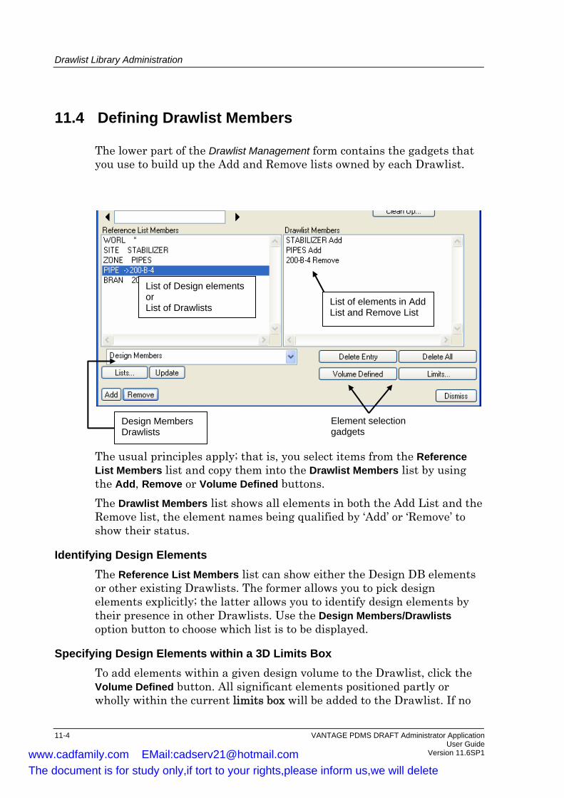
Drawlist Library Administration
11.4 Defining Drawlist Members
The lower part of the Drawlist Management form contains the gadgets that you use to build up the Add and Remove lists owned by each Drawlist.
The usual principles apply; that is, you select items from the Reference List Members list and copy them into the Drawlist Members list by using the Add, Remove or Volume Defined buttons. The Drawlist Members list shows all elements in both the Add List and the Remove list, the element names being qualified by ‘Add’ or ‘Remove’ to show their status.
List of Design elements or List of Drawlists List of elements in Add
List and Remove List
Design Members Drawlists
Element selection gadgets
Identifying Design Elements The Reference List Members list can show either the Design DB elements or other existing Drawlists. The former allows you to pick design elements explicitly; the latter allows you to identify design elements by their presence in other Drawlists. Use the Design Members/Drawlists option button to choose which list is to be displayed.
Specifying Design Elements within a 3D Limits Box To add elements within a given design volume to the Drawlist, click the Volume Defined button. All significant elements positioned partly or wholly within the current limits box will be added to the Drawlist. If no
11-4 VANTAGE PDMS DRAFT Administrator Application User Guide Version 11.6SP1 www.cadfamily.com EMail:[email protected]
The document is for study only,if tort to your rights,please inform us,we will delete

Drawlist Library Administration
limits box is currently defined, you will be presented with a Drawlist Limits form on which you can enter coordinates of two opposing corners of the required volume.
Deleting an Entry from the Drawlist Members List To delete an entry from the Drawlist, highlight the relevant line in the Drawlist Members list and click the Delete Entry button. The selected line may be either an Add entry or a Remove entry.
VANTAGE PDMS DRAFT Administrator Application 11-5 User Guide Version 11.6SP1 www.cadfamily.com EMail:[email protected]
The document is for study only,if tort to your rights,please inform us,we will delete

Drawlist Library Administration
11-6 VANTAGE PDMS DRAFT Administrator Application User Guide Version 11.6SP1 www.cadfamily.com EMail:[email protected]
The document is for study only,if tort to your rights,please inform us,we will delete

12 Tag Rule Library Administration
This chapter explains how you set up Tag Rule Sets (TRST) and Tag Rules (TAGR), within Tag Rule Libraries (TRLB). When accessed during normal DRAFT drawing operations, each TAGR references a Tagging Template (which may be either a SYTM or a TXTM; see Chapter 8). Tag rules determine which items will be tagged in the View graphics. Note: The DEPT Project_Libraries, supplied as part of the standard
product, contains a LIBY named DRA/PRJ/AUTOTAG, which holds sample tag rule libraries for various disciplines.
12.1 Entering Auto Tagging Administration Mode
From one of the DRAFT Administration menus, select Draft>Tagging Rules. The main menu will change to the DRAFT Tagging Rules Administration menu. The menu hierarchy illustrated in Appendix A.10. All menu selections specified in the remainder of this chapter refer to the Auto Tagging menu unless otherwise stated.
12.2 Creating a Tag Rule Library
To create a new TRLB, proceed as follows: 1. Navigate to the appropriate LIBY level in the existing hierarchy or,
if necessary, use Create>Library to add a new LIBY. 2. Select Create>Tagrule Library. It is recommended that you give the
new TRLB a name to make its use as a Tag Rule Library obvious to users.
You will be presented automatically with a Tagging Library form that allows you to define TRSTs and their member TAGRs. The Tagging Library form will be considered in two stages: • The upper part of the form is concerned with the creation and
deletion of TRSTs within a TRLB. This part of the form is explained in Section 13.3.
• The lower part of the form enables you to create TAGRs, to define the types of element to which they are to be applied, and to set references
VANTAGE PDMS DRAFT Administrator Application 12-1 User Guide Version 11.6SP1 www.cadfamily.com EMail:[email protected]
The document is for study only,if tort to your rights,please inform us,we will delete

Tag Rule Library Administration
to the templates which control the format of the associated tags. This part of the form is explained in Section 13.4.
12.3 Creating and Deleting Tag Rule Sets
The upper part of the Tagging Library form shows the name of the current LIBY and has an option button which allows you to switch to any TRLB owned by that LIBY. It also incorporates a list of TRSTs within the current TRLB.
Current Library Selected TRLB
List of TRSTs in selected TRLB
Specifying the Owning Tag Rule Library To specify the TRLB whose member TRSTs you wish to modify, use the Tag Rules Library option button to select from those available in the current LIBY. The TRSTs owned by the current TRLB will be shown in the Tag Ruleset list (or None if you have just created the TRLB).
Creating a Tag Rule Set To create a new TRST, click the Create Ruleset button and give the new TRST a name. The name will be added to the displayed list and will be highlighted as the current selection.
Deleting a Tag Rule Set To delete a TRST from the current TRLB, highlight it in the Tag Ruleset List and click the Delete Ruleset button.
12-2 VANTAGE PDMS DRAFT Administrator Application User Guide Version 11.6SP1 www.cadfamily.com EMail:[email protected]
The document is for study only,if tort to your rights,please inform us,we will delete

Tag Rule Library Administration
12.4 Creating and Setting Up Tag Rules
The lower part of the Tagging Library form contains all of the gadgets necessary to create TAGRs, to define the types of element to which they are to be applied, and to set references to the templates which control the format of the associated tags.
Current TAGR Design element class to which TAGR applies PDMS expression
Associated label template
Viewing Tag Rules The Rule option button displays a list of all TAGRs in the current TRST (i.e. the TRST highlighted in the Tag Ruleset list). It is also used to change the current TAGR if you wish to modify its attribute settings.
Creating a Tag Rule Note: Tag Rules are always named automatically when they are
created. You cannot change the name. The attributes values for the newly created TAGR are defined by the current settings of the other gadgets on the form (Tag, With, Template Reference, etc.), so set these as explained in the following paragraphs before you create the TAGR.
To create a new TAGR, click the Create button. The TAGR will be named automatically and its name will be added to the Rule option button list as the current selection.
Deleting a Tag Rule To delete a TAGR from the current TRST, make the TAGR current (by using the Rule option button) and click the Delete button.
VANTAGE PDMS DRAFT Administrator Application 12-3 User Guide Version 11.6SP1 www.cadfamily.com EMail:[email protected]
The document is for study only,if tort to your rights,please inform us,we will delete

Tag Rule Library Administration
Specifying the Elements to which Rules Apply You can specify the type of element or a list of named elements, as follows: To specify the type of element to which the current TAGR is to be applied, select a design element class from the Tag drop-down list.
Criteria for Tag Rule Application To apply restrictions to the elements specified by the Tag option, type a PDMS expression into the With text box. For example, if the Tag gadget specifies Branches, you might use the With qualifier to enter ‘(HBOR GT 100) AND (TBOR GT 80)’ to compile the overall specification ‘Branches with HBOR greater than 100 mm and TBOR greater than 80 mm’.
Associating a Label Template with a Tag Rule To select a label template that will define the appearance of tags generated by the current TAGR, use the Template Reference Select button. You will be presented with a Select Template for Auto Tagging form. On this form, select the Label Library required and, from the displayed templates, pick the one which is to be associated with the current TAGR. Apply this to the current TAGR.
Associating a Drawlist with a Tag Rule To specify a drawlist which is to be associated with the current TAGR (such that only items in the drawlist will be tagged), click the Drawlist Reference button. You will be presented with a Drawlist Reference form. On this form, select the Drawlist Library required and, from the displayed list, pick the Drawlist which is to be associated with the current TAGR. Apply this to the current TAGR. To modify the content of the drawlist associated with the current TAGR, click the Drawlist button. You will be presented with a Drawlist Management form. On this form, select the Drawlist whose member list is to be modified and add or remove design elements. Apply this to the current TAGR in the usual way. Apply the changes to the current TAGR.
12-4 VANTAGE PDMS DRAFT Administrator Application User Guide Version 11.6SP1 www.cadfamily.com EMail:[email protected]
The document is for study only,if tort to your rights,please inform us,we will delete

13 ADP Administration
This chapter explains what the DRAFT Administrator must do to set up a project to allow Automatic Drawing Production (ADP) for Pipework and Steelwork. DRAFT provides for three types of Automatic Drawing Production (ADP): • General ADP, used for Equipment and Piping. See Section 13.1. • Steelwork Detailing. See Section 13.2. • Hanger and Support ADP. The Administrator's role is setting up
suitable backing Sheets, as described in Section 13.3. The User information for Hangers and Supports ADP is given in Support Design Using PDMS.
Note: ADP administration is accessed through the Automatic Drawing Production Application, and not through the Administration Application. The forms and menu options are only available if you are a member of the DRAFTADMIN team.
13.1 General ADP
The General ADP options create drawings from specified parts of the Design model in the usual way, and then add annotation according to defaults set up by the System Administrator. The defaults are stored in files, and there are different defaults suitable for different types of drawings. The user must load a suitable file for the drawing being produced. The ADP application can add dimensions, labels, and schedules to a drawing. It can also add graphical information such as equipment centrelines and pipe end symbols. The ADP application recognises different Types of dimensions: • Type 1 dimensions are used for pipework. • Type 2 dimensions are used for equipment centres. • Type 3 dimensions are used for gridlines. You can control the way in which each type of dimension is displayed. You can specify the order in which types of dimensions are generated.
VANTAGE PDMS DRAFT Administrator Application 13-1 User Guide Version 11.6SP1 www.cadfamily.com EMail:[email protected]
The document is for study only,if tort to your rights,please inform us,we will delete

ADP Administration
For each type, you can set up Rules using PML expressions to define how different PDMS element types are dimensioned.
13.1.1 Setting the ADP Defaults
The ADP Defaults are set on the ADP Defaults File Editor form, which is displayed when you select Settings > General ADP Defaults from the Main ADP Menu. There are several defaults files supplied with the product, stored in the directory %PDMSDFLTS%. The file names are of the form DRA-GENADP -*. These files can be modified, and you can create your own new files as well. You can load a defaults file in the following ways: • Select File > Load From from the menu at the top of the form. A File
Browser will be displayed, showing the files in the given directory. Select the file you want.
• Press the Browse button on the body of the form. A File Browser will be displayed.
• If you already have an ADP Drawing displayed, you can select From View and pick any item in the View. The Defaults file used to create the View will be loaded.
When a defaults file is loaded, the ADP Defaults File Editor form will be filled in with details from the file. You can change the defaults as described in the following sections. The File Header text box shows a description of the type of defaults. The text boxes labelled Type 1, Type 2 and Type 3 show the type of dimensioning controlled by the given types. As supplied, Type 1 is Piping, Type 2 is Equipment and Type 3 is Gridline. Not all types are used in all default files: when a type is not used in the current default file it is shown on the form as Unused. To change a type of dimensioning, click on the appropriate Type button, and a Type n Defaults form will be displayed. For information about the options on the Type n Defaults forms, see the online help. The General, Schedules and Tagging buttons allow you to set defaults as described in the following sections.
13-2 VANTAGE PDMS DRAFT Administrator Application User Guide Version 11.6SP1 www.cadfamily.com EMail:[email protected]
The document is for study only,if tort to your rights,please inform us,we will delete

ADP Administration
The General ADP Defaults Form The General ADP Defaults form is displayed when you press General on the
ADP Defaults File Editor form. This form allows you to: • Restrict USER Access. If this button is switched off, users will be able
to access the Modify User Defaults form and so change the defaults. If this button is switched on, users will not be able to modify the defaults files from the user forms. The only way to change them will be from this form, which is only accessible to users who are members of the DRAFTADMIN team. The Modify button on the Modify User Defaults form and the Edit button on the View Function form will not be active.
• Set the Annotation Processing Order. In the text box, enter the order in which different types of annotation are to be processed. As supplied, the order is 3, 2 1. Each Type n Defaults form has an option where you can define how inherited dimension points are handled, by specifying which Type they are copied from: the processing order must ensure that the dimension points to be copied already exist.
Type 3
Type 2
Type 2 dimension point inherited from Type 3
• Create any Representation Rulesets needed. If the standard
Representation Rulesets are required, this text box should contain the text Standard.
• Create any rules needed to control which elements are ADDed or REMOVEd from Drawlists defined by volume. As supplied, all elements within the Volume will be added, but elements of type PIPE that are owned by a Zone with Function set to Heating or Electrical will be removed.
For more information about editing rules, see the online help.
The ADP Defaults - Schedules and Tagging Forms The ADP Defaults - Schedules form is displayed when you press Schedules on the ADP Defaults File Editor form. The ADP Defaults - Tagging form is displayed when you press Tagging on the ADP Defaults File Editor form.
VANTAGE PDMS DRAFT Administrator Application 13-3 User Guide Version 11.6SP1 www.cadfamily.com EMail:[email protected]
The document is for study only,if tort to your rights,please inform us,we will delete

ADP Administration
For more information on the forms, see the online help.
13.1.2 Creating a Tagging Library
The tagging facilities used in ADP are based on the standard DRAFT automatic tagging functionality. You need to be familiar with this before reading any further. The ADP PGA defaults file contains an entry to allow the administrator to define what tag rule set element will be available to the user during use of the ADP system. The supplied system refers to a TRLB called DRA/PRJ/ADP/TAGGS/PGA that contains the TRST’s that the user accesses on the tagging creation form. Each TRST is represented by toggle gadgets on the user’s form. In order to create your own TRLB for tagging you simply create the TRSTs and their TAGR elements with tag rules and tagging templates as required. The only important consideration for the ADP system is that the last part of the TRSTs name is used on the user’s form, and so this should describes the tagging available to the user. For example, if the TRST is named /MYTAG/Instruments, then Instruments will appear on the user’s tagging creation form. Some example tagging templates are provided in the label libraries DRA/PRJ/ADP/TAGGS/PGA/TXTM and DRA/PRJ/ADP/TAGGS/PGA/SYTM but you are free to define or use any symbol or text template as required.
13.1.3 Creating a Schedule Library
The schedule facilities used in ADP are based on the standard DRAFT automatic tagging functionality, and you should be familiar with this before reading any further. The ADP PGA defaults file contains an entry to allow the administrator to define what tag rule set element will be available to the user during use of the ADP system. The supplied system refers to a TRLB called DRA/PRJ/ADP/SCHE/PGA that contains the TRSTs that the user accesses on the schedule creation form. Each TRST is represented by a toggle and modify button gadget group on the user’s form. In order to create your own TRLB for schedules and any number of TRSTs below this, each of which represents an available schedule for use
13-4 VANTAGE PDMS DRAFT Administrator Application User Guide Version 11.6SP1 www.cadfamily.com EMail:[email protected]
The document is for study only,if tort to your rights,please inform us,we will delete

ADP Administration
by the user. The TRSTs and their constituent TAGRs have to be built with the following naming conventions:
/MySchedules/NozzlesTRST
TAGR /ENTRYowner-name /LOCALowner-name TAGR /LOCAL can reference any STYM or TXTM as required. This tag rule is responsible for generating the tags local to the design graphics. TAGR /ENTRY has to reference a special SYTM which in turn has references to other SYTMs and is responsible for generating the tabular format entries generated as part of the schedule. In order to generate a matching set of local and table tags it is important that both TAGRs have the same criteria. The SYTM referenced by the TAGR /ENTRY has an associated set of SYTMs as shown below, where prefix can be any prefix name for the SYTMs, but the same prefix is used to identify all three SYTMs required to construct the schedules table. Example The following example is based on the Project Libraries supplied in the Sample Project, under DRA/PRJ/ADP/SCHED:
VANTAGE PDMS DRAFT Administrator Application 13-5 User Guide Version 11.6SP1 www.cadfamily.com EMail:[email protected]
The document is for study only,if tort to your rights,please inform us,we will delete

ADP Administration
TMRFTRST/NOZZLES-1
TAGR/NOZZLES/LOC
TAGR/NOZZLES/ENTRY
Reference by namefrom prefix /ENTRY
Schedule
View
TXTMBTEX 'X0 Y-10'
Defines offsetbetween entries
Defines labelin View
TMRFTXTM
SYTMprefix /OFFSET
Reference by namefrom prefix /ENTRY
N1
Nozzle Schedule
N1Nozzle Size North East Elevation
200 +1100 +200 +3100
SYTMprefix /ENTRY
SYTMprefix /HEADER
Each of the functions of the three schedule table SYTMs is explained below:
prefix/ENTRY The SYTM used to construct the table entries
prefix/HEADER The SYTM used to construct the table header
prefix/OFFSET The SYTM used to determine how each of the table entries is positioned, during construction of the table
The SYTM prefix/OFFSET contains a single TEXP whose BTEX determines how each table entry is positioned with respect to the previous. The BTEX simple states the OFFSET for each table entry in the standard X and Y format. For example:
13-6 VANTAGE PDMS DRAFT Administrator Application User Guide Version 11.6SP1 www.cadfamily.com EMail:[email protected]
The document is for study only,if tort to your rights,please inform us,we will delete

ADP Administration
BTEX = ’X 0 Y -10’
This means that each table entry is offset by -10 in the Y direction, therefore producing a vertical table that grows down the sheet from the origin position. The origin and extent positions for any schedules created are initially taken from a special note created in the BACK by the administrator. See the next section for details of how to implement this.
13.1.4 Backing Sheet Controls
The backing sheet referenced by an ADP sheet can contain two sets of information to allow the ADP annotation and view creation to be more automated. The following sections describe the types of additional information that can be generated under a BACK for use by the ADP system. The general ADP application makes use of special information stored on the backing sheet in the form of Notes, which specify where certain types of annotation generated by ADP will be located on the sheet. If this information is not present on the backing sheet the application will either prompt the user for input or not allow the user access to the associated automatic annotation options. All the Notes have visibility set to false. Reference Drawings This is the area on the Sheet that is available for the user to insert a list of Reference Drawings. It is defined under a Note named back_sheet_name/REFDRWGS. The Note contains TEXPs that are used to represent reference drawings associated with a sheet. Each TEXP should be positioned and have attributes set as required. The TEXP is copied from the backing sheet onto the user’s sheet during reference drawing definition. The Note should also contain a rectangle whose area represents the available area taken by the reference drawing texts, which is used during zoom operations. Sheet Limits This is the area available on the backing sheet where the View will be created. It is defined under a Note named back_sheet_name/LIMITS. The Note should contain just one RECT element whose limits correspond to the available free space on the BACK. This LVIS of the NOTE should be set to FALSE in order to inhibit the display of the rectangle on the user’s sheet.
VANTAGE PDMS DRAFT Administrator Application 13-7 User Guide Version 11.6SP1 www.cadfamily.com EMail:[email protected]
The document is for study only,if tort to your rights,please inform us,we will delete
ADP Administration
Schedules This is the area on the Sheet that will be used to display Schedules. The origin of the schedule table and its maximum extent is defined on the backing sheet. Only one origin and extent definition can be added to a BACK and this is initially used by ALL schedules that are created by the user. The user always has the option to re–define the two attributes for any schedule created. The ORIGIN and EXTENT information gives the application a starting point for any schedules. To create the ORIGIN and EXTENT positions on the backing sheet create a NOTE under the required BACK with the name back_sheet_name/SCHEDULE. This note should own two MRKP elements named: back_sheet_name/SCHEDULE/ORIGIN and back_sheet_name/SCHEDULE/EXTENT SCHEDULE/ORIGIN should be positioned where the origin of the schedule will be positioned and from where the schedule will be built. SCHEDULE/EXTENT should be positioned at a point past which the schedule should not be built. All subsequent schedule entries that would exceed this extent position are hidden and the user is warned of the schedule overflow. Keyplan This is the area on the Sheet that will be used to display a Keyplan. It is defined under a Note named back_sheet_name/KEYPLAN. This note should contain one MRKP element to determine the position for the Sheet’s keyplan OLAY. The MRKP must be named: back_sheet_name/KEYPLAN/ORIGIN. The Note should also contain a rectangle whose area represents the available area taken by the reference drawing texts, which is used during zoom operations. Title This is the area on the Sheet that will be used to display the title block of the backing sheet. It is defined under a Note named back_sheet_name/TITLE. The Note can contain 2D primitives to define the geometry of the Title Block. It should have a Rectangle (the first primitive in the list, or first Rectangle in the list) with NLPN set to OFF, whose area will define the area occupied by the title block. This is used during zoom operations.
13-8 VANTAGE PDMS DRAFT Administrator Application User Guide Version 11.6SP1 www.cadfamily.com EMail:[email protected]
The document is for study only,if tort to your rights,please inform us,we will delete

ADP Administration
Summary The following table summarises the special Notes that can exist on the backing sheets, and more details are given below.
Name Use Action if not present /REFDRWGS Reference Drawing Information GUI gadgets inactivated /LIMITS Defines available sheet area Whole sheet area assumed /SCHEDULE Defines schedule position info User prompted for positions /KEYPLAN Position for keyplan OLAY Positioned at X0 Y0 /TITLE Area for zooming on TITLE BLOCK GUI gadgets inactivated
You can refer to the standard A0 backing sheet, /DRA/MAS/BACKS/METRIC/A0, in the Department Draft_Libraries, as an example.
13.2 Steelwork Detailing ADP
This Section describes the administration tasks which you will need to carry out for Steelwork Detailing Automatic Drawing Production (SDA), which allows the DRAFT User to produce dimensioned and annotated drawings of the most commonly used structural elements (straight Beams and Columns, and flat Plates) automatically. The requirements for SDA are: • A Sheet Library containing suitable backing sheets • A Symbol Library containing suitable annotation symbols • A Style Library containing suitable styles • A Representation Rules Library containing rules defining which
Styles are used for displaying the profiles. • One or more SDAOPT elements, which set the SDA defaults that the
SDA User will initially see displayed on the SDAOPT form.
VANTAGE PDMS DRAFT Administrator Application 13-9 User Guide Version 11.6SP1 www.cadfamily.com EMail:[email protected]
The document is for study only,if tort to your rights,please inform us,we will delete

ADP Administration
The backing sheets and SDAOPT elements supplied with the product are in the Department Master_Libraries. The backing sheets in the Library DRA/MAS/BACKS can be used for SDA. The Library DRA/MAS/SDADP contains Libraries of Styles, Symbols and Representation Rules for SDA. It also contains two SDAOPT elements: SDA-Default SDA-Main-Views The only difference is that the SDA-Main-Views file will not output detail views. Note: Occasionally fabrication drawings produced by SDADP will be
under-dimensioned, although it will always be at least 70% of that required for fabrication of the component. If a dimension is missing, it may be due to the way the catalogue component is defined.
13.2.1 The SDA Options
The attributes of the SDAOPT element define the options that will be used. You can change the attributes of an SDAOPT element or create a new one using the Steelwork Detailing Options form, described in Drawing Production Using PDMS. The UPDCB attribute of the SDAOPT element controls which customisation macro is run: it is set to:
%PDMSDFLTS%/DRA-SDADP-MACRO
See the next section for information about the macro. If you create your own SDAOPT element, it will be created in the current LIBY, if there is one. If your current element is the World, a new LIBY will be created to store the options in. You will have to give this LIBY a suitable name, if required, after the SDAOPT element has been created.
13.2.2 The SDA Customisation Macros
The two SDA customisation macros supplied in the PDMSDFLTS directory (SDA-Default and SDA-Main-Views) control the naming conventions for the Sheets generated by SDA, the pens and the positions of text on the Sheets You can edit these macros, or write your own, if you are familiar with PML, the AVEVA Programming Language. See the VANTAGE Plant Design Software Customisation Guide and the VANTAGE Plant Design Software Customisation Reference Manual for more information. A
13-10 VANTAGE PDMS DRAFT Administrator Application User Guide Version 11.6SP1 www.cadfamily.com EMail:[email protected]
The document is for study only,if tort to your rights,please inform us,we will delete

ADP Administration
customisation macro is called once for each major item created by SDA. This means that you can define the parameters used to draw each type of element. Note that the supplied macros do not name the DEPTs REGIs and DRWGs created by SDA. You will have to give them suitable names, if required, after an SDA run.
13.3 Hangers and Supports ADP
This section describes how the backing sheets supplied for Hanger and Supports ADP are set up. The Sheets are supplied in the Library Each Backing Sheet contains twelve member notes. Each Note owns TEXPs to help define the specific area of the sheet. Some TEXPs are not used at this release, and some Notes contain 2D primitives that are not used at this release. The TEXPs must be kept as members of certain Notes for the DRAFT GUI to work correctly. The values in the BTEXT of the TEXP elements can be whole numbers, decimals or fractions. The standard backing sheet has the following members. Those marked with an asterisk are required, the other are optional.
* NOTE 1 /DRA/MAS/H&S_A2/HS_Matl_List * NOTE 2 /DRA/MAS/H&S_A2/Frame * NOTE 3 /DRA/MAS/H&S_A2/Supported_Items * NOTE 4 /DRA/MAS/H&S_A2/Support_Steel NOTE 5 /DRA/MAS/H&S_A2/TitleBlock NOTE 6 /DRA/MAS/H&S_A2/TitleBlockData NOTE 7 /DRA/MAS/H&S_A2/DrawingNotes NOTE 8 /DRA/MAS/H&S_A2/Address NOTE 9 /DRA/MAS/H&S_A2/SmallPrint NOTE 10 /DRA/MAS/H&S_A2/ModBlock NOTE 11 /DRA/MAS/H&S_A2/HashTexts * NOTE 12 /DRA/MAS/H&S_A2/LIMITS
VANTAGE PDMS DRAFT Administrator Application 13-11 User Guide Version 11.6SP1 www.cadfamily.com EMail:[email protected]
The document is for study only,if tort to your rights,please inform us,we will delete

ADP Administration
NOTE 1: /DRA/MAS/H&S_A2/HS_Matl_List This Note contains TEXPs that define settings for the Hanger Bill of Materials. The Members of this Note do not have to be named. TEXP 1 BTEX attribute set to
H&S_MATL_LIST:value1, value2 where value1and value2 specify the starting point of the Bill of Material. This position is based on the lower left-hand corner of the owning BACK size.
TEXP 2 BTEX attribute set to REF_X:value where value sets the horizontal (X) placement of the part number hanger element in the BOM, The position is a specified distance from the left-hand edge of the BOM area defined by TEXP 1.
TEXP 3 BTEX attribute set to DESC_X:value where value sets the horizontal (X) starting position of the hanger element in the BOM. The position is a specified distance from the left-hand edge of the BOM area defined by TEXP 1.
TEXP 4 BTEX attribute set to DESC_MAX_CHAR_X:value where value specifies the number of characters allowed in each line of the material description. Additional characters will wrap onto the next line.
TEXP 5 BTEX attribute set to DIAM_X:value where value specifies the distance from the left edge of the BOM area when the diameter setting of the hanger element is to be placed
TEXP 6 BTEX attribute set to LENGTH_X:value where value specifies the distance from the left-hand edge of the BOM area where the length text of the hanger element is to be placed.
TEXP 7 BTEX attribute set to QTY_X:value where value specifies the distance from the left-hand edge of the BOM where the quantity of the hanger parts is to be placed.
13-12 VANTAGE PDMS DRAFT Administrator Application User Guide Version 11.6SP1 www.cadfamily.com EMail:[email protected]
The document is for study only,if tort to your rights,please inform us,we will delete

ADP Administration
TEXP 8 BTEX attribute set to LINE_SPACE:value where value specified the distance between each line in the description part of the BOM.
TEXP 9 BTEX attribute set to ITEM_SPACE:value where value specifies the distance between each part number description down the BOM listing.
TEXP 10 BTEX attribute set to UNBOLT_PACK_EXCLUDE:word, word Not used at this release
TEXP 11 BTEX attribute set to LAYE_PURP:word where word specified distance from the left-hand edge of the BOM area defined by TEXP 1.
TEXT 12- BTEX set to SLAB_SORF:name The name specified is that of the TAGR to be referenced for the support labels
NOTE 2 /DRA/MAS/H&S_A2/Frame This Note contains the 2D drafting primitives that define the main backing Sheet border, similar to the backing sheets for standard drawing sheets. NOTE 3 /DRA/MAS/H&S_A2/Supported_Items This Note displays a table that lists the pipes that are being supported. TEXP 1 BTEX set to
BOM:SIB Not used at this release
TEXP 2 BTEX set to HEADER_POS:value1,value2
where value1 and value2 define the position of a SLAB that references the supported item table symbol template (SYTM). The origin of the SYTM is the upper left corner of the table.
TEXP 3 BTEX set to LABEL_POS:value1,value2 where value1 and value2 define the position of the first SLAB in the support item table. The position is a distance from the lower left corner of the owning BACK.
VANTAGE PDMS DRAFT Administrator Application 13-13 User Guide Version 11.6SP1 www.cadfamily.com EMail:[email protected]
The document is for study only,if tort to your rights,please inform us,we will delete

ADP Administration
TEXP 4 BTEX set to TILE_X:value where value is the horizontal distance between the reference SLABs in the support item table.
TEXP 5 BTEX set to TILE_Y:value where value is the vertical distance between the reference SLABs in the support item table.
TEXP 6 BTEX set to TILE_MAX:value Not used at this release
TEXP 7 BTEX set to TAGGING:name where name is the name of the TRST to be used for the supported items listing. The TRST has two member TAGRs, LOCAL and LABEL. These TAGRs are copied into the appropriate layer and the member SLABs that are generated reference them. The LOCAL TAGR defines criteria for locating the Part Number SLAB in the Views. The LABEL TAGR defines criteria for the Support Table BOM and references that specific label template.
TEXP 8 BTEX set to TITLE:text where text is used in the log file to mark the start of messages relating to symbolic labels in the supported item layer owned by the View.
NOTE 4 /DRA/MAS/H&S_A2/Support_Steel This table displays the list of member parts, listing the size of each member and its required length. TEXP 1 BTEXT set to BOMST:STB
Not used at this release TEXP 2 BTEX set to
HEADER_POS:value1,value2 Value1 and value2 define the upper left corner position of the steel BOM table. The table template (SYTM) is referenced by a SYMB that is created under a VNOT in the Steel BOM layer of the first View when the support drawing is generated.
13-14 VANTAGE PDMS DRAFT Administrator Application User Guide Version 11.6SP1 www.cadfamily.com EMail:[email protected]
The document is for study only,if tort to your rights,please inform us,we will delete

ADP Administration
TEXP 3 BTEX set to LABEL_POS:value1,value2 where value1 and value2 define the position of the first SLAB in the steel BOM list. This position is the distance from the lower left corner of the owning BACK.
TEXP 4 BTEX set to TILE_X:value where value specifies the horizontal distance between SLABs in the support material list.
TEXP 5 BTEX set to TILE_MAX:value Not used at this release
TEXP 6 BTEX set to TILE_Y:value where value specifies the vertical distance between SLABs in the support material list.
TEXP 7- BTEX set to TAGGING:name where name specifies the name of the TRST that owns the TAGRs to be used for the support items listing.
TEXP 8 BTEX set to TAGGING:name where name specifies the name of the TRST that owns the TAGRs to be used for the structural support steel list BOM. The TRST has two member TAGRs, LOCAL and LABEL. These TAGRs are copied into the appropriate layer and the member SLABs that are generated reference them. The LOCAL TAGR defines criteria for locating the Part Number SLAB in the Views. The LABEL TAGR defines criteria for the Support Material Table and references that specific label template.
TEXP 9 BTEX set to TITLE:text where text is used in the log file to indicate the start of messages relating to symbolic labels in the support steel layer owned by the View.
VANTAGE PDMS DRAFT Administrator Application 13-15 User Guide Version 11.6SP1 www.cadfamily.com EMail:[email protected]
The document is for study only,if tort to your rights,please inform us,we will delete

ADP Administration
NOTE 5 /DRA/MAS/H&S_A2/TitleBlock This Note contains TEXPs that define the title block layout such as, date, checked, approved etc. These TEXPs have the BTEX attribute set to fixed information. They are not set to extract data through hash codes. Two TEXPs in this Note are named DRA/MAS/H&S_A2/Scale and DRA/MAS/H&S_2/Proj. Both TEXPs are at specified positions on the sheet but the BTEX attribute is not set in either case. These two TEXPs are used for placement of the view scale and angle projection specified from the overall default settings. The creation of the drawing is not abandoned if the Note or the two named TEXPs do not exist. NOTE 6 /DRA/MAS/H&S_A2/TitleBlockData The TEXPs in this Note are similar to those stored in the Titleblock Note. By default, the visibility of this Note is turned off. When the H&S drawing is generated PDMS looks for a note in the backing sheet ending in TitleBlockData. To avoid an error message in the batch log file this note should exist. NOTE 7 /DRA/MAS/H&S_A2/DrawingNotes This Note contains one TEXP. The BTEX is set to NOTE_WIDTH:30 Not used at this release.
NOTE 8 /DRA/MAS/H&S_A2/Address This Note contains one symbol. It could be used to reference a company logo symbol template and be positioned were required. NOTE 9 /DRA/MAS/H&S_A2/SmallPrint This Note does not contain any members. NOTE 10 /DRA/MAS/H&S_A2/ModBlock This Note contains TEXPs that define the revision area block layout of the AVEVA backing sheet. These TEXPs have the BTEX attribute set to fixed information. They are not set to extract data through hash codes. NOTE 11 /DRA/MAS/H&S_A2/HashTexts The TEXPs in this Note define the intelligent text hash codes extracting the AUTHOR, DATE and NAME from the owning DRWG and their placement on the backing. A fourth TEXP extracts the title attribute from the hanger or support drawing sheet. The Drawing and Sheet titles attributes are preset and filled in from the file PDMSUI>DRA>SUPP>UDRWGMAK. Lines 63 and 64 of this file set
13-16 VANTAGE PDMS DRAFT Administrator Application User Guide Version 11.6SP1 www.cadfamily.com EMail:[email protected]
The document is for study only,if tort to your rights,please inform us,we will delete

ADP Administration
the drawing title attribute and lines 108 and 109 set the sheet title attribute.
NOTE 12 /DRA/MAS/H&S_A2/LIMITS This note contains one rectangle. The rectangle defines the area on the hanger and support drawing where the Views will be created. It should be noted that placement and sizing of this rectangle should be kept clear of the Supported Item and Support Steel BOM lists to maintain clarity.
VANTAGE PDMS DRAFT Administrator Application 13-17 User Guide Version 11.6SP1 www.cadfamily.com EMail:[email protected]
The document is for study only,if tort to your rights,please inform us,we will delete

ADP Administration
13-18 VANTAGE PDMS DRAFT Administrator Application User Guide Version 11.6SP1 www.cadfamily.com EMail:[email protected]
The document is for study only,if tort to your rights,please inform us,we will delete

14 AUTODRAFT Administration
The AUTODRAFT option of the Administration menu allows you to access the AUTODRAFT Symbol Editor (allowing you to convert symbols created in AutoCAD into a form usable by PDMS) and the Frame Editor (allowing you to take drawing frames created in AutoCAD and convert them into a PDMS usable format). You can also import symbols and sheet frames created in AutoCAD to be used in PDMS.
14.1 Accessing AUTODRAFT Administration
To display the AUTODRAFT Administration menu bar, select Draft>AUTODRAFT. The menu hierarchy is shown in Appendix A.
14.2 Starting the Symbol Editor
The Symbol Editor enables symbols created in AutoCAD to be converted into a PDMS DRAFT command macro that can then be used to create the equivalent symbols as DRAFT Symbol Template (SYTM) elements. If any of the SYTMs thus defined already exist in the current DRAFT Symbol Library then the old 2D primitives are deleted and replaced by the new definition. 1. Select Draft > AUTODRAFT to bring up the AUTODRAFT
Administration menus. 2. Select Edit > Symbols from the menu bar. This gives the AutoDRAFT
Symbol Editor form - see below. 3. Make the Symbol Library (SYLB) that you wish to contain the
returning Symbol Editor generated symbols the current element. 4. If you wish the AutoCAD work directory to be other than the local
one, backspace in the AutoCAD Work Directory text box until it is clear, then type in the required directory name.
VANTAGE PDMS DRAFT Administrator Application 14-1 User Guide Version 11.6SP1 www.cadfamily.com EMail:[email protected]
The document is for study only,if tort to your rights,please inform us,we will delete
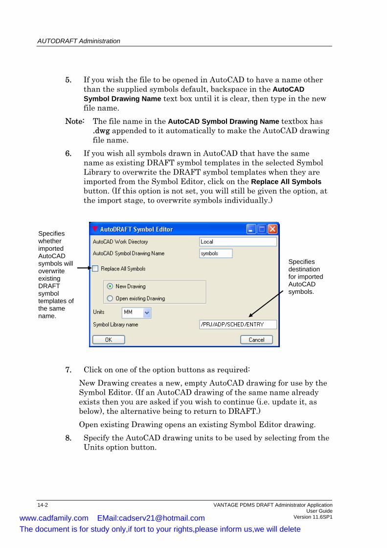
AUTODRAFT Administration
5. If you wish the file to be opened in AutoCAD to have a name other than the supplied symbols default, backspace in the AutoCAD Symbol Drawing Name text box until it is clear, then type in the new file name.
Note: The file name in the AutoCAD Symbol Drawing Name textbox has .dwg appended to it automatically to make the AutoCAD drawing file name.
6. If you wish all symbols drawn in AutoCAD that have the same name as existing DRAFT symbol templates in the selected Symbol Library to overwrite the DRAFT symbol templates when they are imported from the Symbol Editor, click on the Replace All Symbols button. (If this option is not set, you will still be given the option, at the import stage, to overwrite symbols individually.)
Specifies whether imported AutoCAD symbols will overwrite existing DRAFT symbol templates of the same name.
Specifies destination for imported AutoCAD symbols.
7. Click on one of the option buttons as required:
New Drawing creates a new, empty AutoCAD drawing for use by the Symbol Editor. (If an AutoCAD drawing of the same name already exists then you are asked if you wish to continue (i.e. update it, as below), the alternative being to return to DRAFT.) Open existing Drawing opens an existing Symbol Editor drawing.
8. Specify the AutoCAD drawing units to be used by selecting from the Units option button.
14-2 VANTAGE PDMS DRAFT Administrator Application User Guide Version 11.6SP1 www.cadfamily.com EMail:[email protected]
The document is for study only,if tort to your rights,please inform us,we will delete

AUTODRAFT Administration
9. If you wish the Symbol Library (SYLB) that you wish to contain the returning Symbol Editor-generated symbols to be other than the shown current element (as selected at step 6), backspace in the Symbol Library Name text entry box until it is clear, then type in the required name.
10. Click on OK. After a short pause, the AutoCAD text window and graphics window (with the specified drawing displayed within it) will appear.
14.3 Starting the Frame Editor
The Frame Editor enables drawing frames created in AutoCAD to be converted into a PDMS DRAFT command macro that can then be used to create the equivalent frames as DRAFT Backing or Overlay Sheet elements within a specified Sheet Library. If the specified Backing/Overlay Sheet already exists in the specified Sheet Library then the old 2D primitives are deleted and replaced by the new definition. 1. Select Draft > Administration > AUTODRAFT to bring up the
AUTODRAFT Administration menus. 2. Make the Sheet Library (SHLB) that you wish to contain the
returning Frame Editor–generated symbols the current element. 3. Select Edit > Sheet Frame from the menu bar. This gives the
AutoDRAFT Frame Editor form:
Specifies destination for imported AutoCAD Backing /Overlay Sheet
Specifies whether Backing Sheet or Overlay Sheet is to be created.
Specifies name of Sheet to be created
VANTAGE PDMS DRAFT Administrator Application 14-3 User Guide Version 11.6SP1 www.cadfamily.com EMail:[email protected]
The document is for study only,if tort to your rights,please inform us,we will delete

AUTODRAFT Administration
4. If you wish the AutoCAD work directory to be other than the local one, backspace in the AutoCAD Work Directory text box until it is clear, then type in the required directory name.
5. If you wish the file to be opened in AutoCAD to have a name other than the supplied pdmsback default, backspace in the AutoCAD Drawing Name text box until it is clear, and then type in the new file name.
Note: The file name in the AutoCAD Drawing Name text box has .dwg appended to it automatically to make the AutoCAD drawing file name.
6. Click on one of the option buttons as required: New Drawing creates a new, empty AutoCAD drawing for use by the Frame Editor. (If an AutoCAD drawing of the same name already exists then you are asked if you wish to continue (i.e. update it, as below), the alternative being to return to DRAFT.) Open existing Drawing opens an existing Frame Editor drawing.
7. Specify the AutoCAD drawing units to be used by selecting from the Units option button.
8. If you wish the Sheet Library (SHLB) that you wish to contain the returning Frame Editor-generated symbols to be other than the shown current element (as selected at step 6.), backspace in the Symbol Library name text box until it is clear, then type in the required name.
9. Select from the option button at the bottom–left of the form whether you wish the imported symbols to create a Backing Sheet or an Overlay Sheet.
10. Enter the name that you wish to give the derived Sheet into the name text box.
11. Click on OK. After a short pause, the AutoCAD text window and graphics window (with the specified drawing displayed within it) will appear.
14.4 Importing Symbols and Backing/Overlay Sheets
Notes: The file import facilities described in this section need only be
used if PDMS and AutoDRAFT are on different hardware platforms. Furthermore, the use of these facilities is optional;
14-4 VANTAGE PDMS DRAFT Administrator Application User Guide Version 11.6SP1 www.cadfamily.com EMail:[email protected]
The document is for study only,if tort to your rights,please inform us,we will delete

AUTODRAFT Administration
provided you first navigate to the correct position in the database hierarchy, the macro file exported from AutoDRAFT can be run into the DRAFT database using the PDMS $M/ command.
If PDMS and AutoCAD are on the same hardware platform, the Symbol or Sheet elements created using AutoCAD can be created in the DRAFT database directly from AutoDRAFT. See the AutoDRAFT Reference Manual for details.
Having created entities in AutoCAD (using the AutoDRAFT Symbol Editor) which can be used as Symbols in DRAFT, they can be imported to DRAFT and Symbol Template (SYTM) elements automatically created. 1. Select Draft>AUTODRAFT to bring up the AUTODRAFT
Administration menus. 2. Select Import>Symbols . . . from the menu bar. This gives the Load
AutoDRAFT Symbols form. 3. If the directory to contain the Symbol creation macro file is not the
local one, backspace in the AutoCAD Work Directory text box until it is clear, then type in the required directory name.
4. If the macro file to be used does not have the supplied default name symbols.mac then backspace in the AutoCAD Symbol Macro text box until it is clear, then type in the new file name.
5. Press OK, and a Backing or Overlay Sheet will be automatically created.
6. If you wish all symbols drawn in AutoCAD that have the same name as existing DRAFT Symbol Templates in the selected Symbol Library to overwrite the DRAFT Symbol Templates when they are imported from the Symbol Editor, click on the Replace All Symbols button. (If this option is not set, you will still be given the option, at the import stage, to overwrite symbols individually.)
The Symbol Library (SYLB) to which the Symbol Templates are to be added is as specified on entry to the Symbol Editor, see page NO TAG. Note: The ways in which AutoCAD entities and attributes are mapped
to DRAFT elements and attributes are described in the AutoDRAFT Reference Manual.
Having created a drawing entity in AutoCAD (using the AutoDRAFT Frame Editor) that can be used as a Backing or Overlay Sheet in DRAFT, it can be imported to DRAFT and a Backing or Overlay Sheet element (as required) automatically created.
VANTAGE PDMS DRAFT Administrator Application 14-5 User Guide Version 11.6SP1 www.cadfamily.com EMail:[email protected]
The document is for study only,if tort to your rights,please inform us,we will delete
AUTODRAFT Administration
1. Select Draft>AUTODRAFT to bring up the AUTODRAFT Administration menus.
2. Select Import>Sheet Frame from the menu bar. This gives the Load AutoDRAFT Sheet Frame form.
3. If the directory to contain the Sheet-creation macro file is not the ‘local’ one, backspace in the AutoCAD Work Directory text box until it is clear, then type in the required directory name. If the macro file to be used does not have the supplied default name pdmsback.mac then backspace in the AutoCAD Sheet Macro text box until it is clear, then type in the new file name.
4. When you press OK, a Backing or Overlay Sheet will be automatically created.
The type of Sheet to be created, and the Sheet Library (SHLB) to which the Sheet is to be added are both as specified on entry to the Frame Editor. If the specified Backing/Overlay Sheet already exists in the specified Sheet Library then the old 2D primitives are deleted and replaced by the new definition.
14-6 VANTAGE PDMS DRAFT Administrator Application User Guide Version 11.6SP1 www.cadfamily.com EMail:[email protected]
The document is for study only,if tort to your rights,please inform us,we will delete

15 Loading Data Files
The Administration option of DRAFT contains a feature that allows you to automatically load data files to create new projects. By using the Load Data File option you can load new project data for Main Libraries, Template Drawings and Application Department.
15.1 Accessing Load Data Files
To load the data files, select Draft > Settings > Load data file from the DRAFT main menu. You can then select the data files you wish to load (Main Libraries, Template Drawings or Application Department).
VANTAGE PDMS DRAFT Administrator Application 15-1 User Guide Version 11.6SP1 www.cadfamily.com EMail:[email protected]
The document is for study only,if tort to your rights,please inform us,we will delete

Loading Data Files
15-2 VANTAGE PDMS DRAFT Administrator Application User Guide Version 11.6SP1 www.cadfamily.com EMail:[email protected]
The document is for study only,if tort to your rights,please inform us,we will delete

16 Updating the Database
There are occasions when the DRAFT database needs to be updated specifically, as opposed to the routine updating that occurs from time to time in normal use. This chapter explains when and how you should do this.
16.1 Updating Picture Files
This operation should be carried out to recover from a corrupt picture file, such as may result from a RECONFIGURER operation, or if an attempt has been made to display a VIEW created using a previous version of DRAFT. Annotation graphics will always be restored but Design graphics may not be. In all such cases, a message alert will be displayed instructing you to carry out the update operation, and this is the only time that the operation should be carried out. Select Graphics > System Update > Picture from the Administration menu.
16.2 Updating Template Instancing
This option (valid at SHEE, BACK, OVER, SYLB or LALB level, or above) scans the database hierarchy and updates all those parts of picture files that use the graphics ‘instancing’ mechanism. For example, a SYMB is an ‘instance’ of a SYTM. OLAY and BACK elements are in the same category. This update should be used to generate the correct graphics after the LIBNO NEW option has been used in RECONFIGURER. Select Graphics > System Update > Instances from the Administration menu.
VANTAGE PDMS DRAFT Administrator Application 16-1 User Guide Version 11.6SP1 www.cadfamily.com EMail:[email protected]
The document is for study only,if tort to your rights,please inform us,we will delete

Updating the Database
16.3 Updating Cross-DB Reference Attributes
This option updates all DRAFT element attributes that refer to elements in the Design database. The settings of such attributes exist as database reference numbers. The updating function operates on the current element. It should only be used if the Design database has been deleted and rebuilt from macros. See Appendix C of the VANTAGE PDMS DRAFT User Guide for further details. Select Graphics > System Update > Refs from the Administration menu.
16.4 Updating Cross-DB Name Attributes
DRAFT elements with attributes that refer to elements in the Design database (the settings of which exist as database reference numbers) also have (hidden) text attributes set to the names of the referenced elements. This option updates the latter attributes, using the settings of the associated reference attributes. The updating function operates on the current element. It should only be used if the Design database has been deleted and rebuilt from macros. See Appendix C of the VANTAGE PDMS DRAFT User Guide for further details. Select Graphics > System Update > Names from the Administration menu.
16-2 VANTAGE PDMS DRAFT Administrator Application User Guide Version 11.6SP1 www.cadfamily.com EMail:[email protected]
The document is for study only,if tort to your rights,please inform us,we will delete

A The DRAFT Administrator Menus
A.1 The Main DRAFT General Administrative Menu
Note: The Administrative menu options that are different from the User Applications are shown in bold. Options that are common to all the Administrative Applications are only shown on the General Administration menu.
This Section shows the part of the menu hierarchy that is common to all Applications.
A.2 Sheet Library Administration
VANTAGE PDMS DRAFT Administrator Application User Guide A-1 User Guide Version 11.6SP1
Reorder . . .
Settings
Delete Modify Create
Department . . . Registry . . . Library . . .
Utilities Settings Query
Create Utilities
Save Work Getwork Extract Control Session Comment . . . Select Working Library. . . Sheet Libraries . . . Symbol Libraries . . . Isodraft Symbol Libraries . . . Label Libraries . . . AutoDRAFT . . . Style Libraries . . . Representation Rules . . . Drawlist Libraries . . . Tagging Rules . . . Area ADP . . . User Applications Modules > Exit
Update > System Update >
Design Design Changes Annotation Annotation Changes Tagging Tagging RegAll
ll Changes
enerate
A
Draft Display Graphics
System Global User Defaults Point Construction Units Enhance Colour Feedback Colour Ppoint Display System Defaults User Defined Pen Settings Plotting Defaults DXF Configuration SettingsDGN Configuration SettingsLoad Data Files
Picture Instances Refs Names
Modify Delete
Note > Library . . . Sheet Library . . . Backing Sheet . . . OverlaySheet . . . View >
Back/Over Layer
CE Members Owner Owner Members Group Members
Group Filter . . . Icon Menu Styles . . .
CE Members Owner Owner Members
Limits-definedUser Defined
Load Text . . . Sketch Drafting . . . Dynamic Primitives
Name Hierarchy Department . . . Registry . . . Library . . .
Definition . . .Attributes . . .
Back/Over Layer Name . . .
Note > Hierarchy > Library . . . Sheet Library > Backing Sheet > OverlaySheet > View >
www.cadfamily.com EMail:[email protected] document is for study only,if tort to your rights,please inform us,we will delete

The DRAFT Administrator Menus
Note: The Draw, Construct and Edit options are the same as in the 2D Drafting Application.
A.3 Symbol Library Administration
Create
Delete Modify
Settings Utilities
Load Text . . . Sketch Drafting . . . Dynamic Primitives
Group Filter . . . Icon Menu Styles . . .
Reorder . . .
Library . . . Symbol Library . . . Symbol Template . . .
CE Members Owner Owner Members Group Members
Definition . . .Attributes . . .
Name Hierarchy > Library . . . Symbol Library >Symbol Template . .
Note: The Draw, Construct and Edit options are the same as in the 2D Drafting Application.
A-2 VANTAGE PDMS DRAFT Administrator Application User Guide Version 11.6SP1 www.cadfamily.com EMail:[email protected]
The document is for study only,if tort to your rights,please inform us,we will delete

The DRAFT Administrator Menus
A.4 ISODRAFT Symbol Library Administration
Delete Modify
Settings Utilities
CE Members Owner Owner Members Group Members
Load Text . . . Sketch Drafting . . . Dynamic Primitives Export Isodraft Symbols Import Isodraft Symbols
Group Filter . . .
Library . . . Isodraft Symbol Library Isodraft Symbol Template . . .
Create
Definition . . .Attributes . . .
Name Hierarchy > Symbol Library > Symbol Template . . .
Note: The Construct and Edit options are the same as in the 2D Drafting Application.
VANTAGE PDMS DRAFT Administrator Application A-3 User Guide Version 11.6SP1 www.cadfamily.com EMail:[email protected]
The document is for study only,if tort to your rights,please inform us,we will delete

The DRAFT Administrator Menus
A.5 Label Library Administration
Create
Delete Modify
Settings Utilities
Load Text . . . Sketch Drafting . . . Dynamic Primitives
Group Filter . . . Icon Menu Styles . . .
Library . . . Label Library . . . Text Template . . . Symbol Template . . .
CE Members Owner Owner Members Group Members
Definition . . .Attributes . . .
Name Hierarchy > Library . . . Label Library > Text Template > Symbol Template . .
A-4 VANTAGE PDMS DRAFT Administrator Application User Guide Version 11.6SP1 www.cadfamily.com EMail:[email protected]
The document is for study only,if tort to your rights,please inform us,we will delete

The DRAFT Administrator Menus
A.6 AUTODRAFT Administration
Delete Import Edit
CE Members Owner Owner Members
Symbols . . . Sheet Frame . . .
Symbols . . . Sheet Frame . . .
VANTAGE PDMS DRAFT Administrator Application A-5 User Guide Version 11.6SP1 www.cadfamily.com EMail:[email protected]
The document is for study only,if tort to your rights,please inform us,we will delete

The DRAFT Administrator Menus
A.7 Style Library Administration
Create Delete Modify
Library . . . Style Library . . Hatching Library . . Change Design Library . . . Change Annotation Library . . .
CE Members Owner Owner Members
Name Hierarchy > Library . . . Style Library . . Hatching Library . . . Change Design Library . . . Change Annotation Library . . .
A-6 VANTAGE PDMS DRAFT Administrator Application User Guide Version 11.6SP1 www.cadfamily.com EMail:[email protected]
The document is for study only,if tort to your rights,please inform us,we will delete

The DRAFT Administrator Menus
A.8 Representation Rule Administration
Create Delete
CE Members Owner Owner Members
Name Hierarchy > Library . . . Representation Library . . . Representation Ruleset . . . Hatching Library . . . Hatching Ruleset . . . Change Library . . . Change Ruleset . . .
Modify
Library . . . Representation Library . . . Representation Ruleset . . . Hatching Library . . . Hatching Ruleset . . . Change Library . . . Change Ruleset . . .
VANTAGE PDMS DRAFT Administrator Application A-7 User Guide Version 11.6SP1 www.cadfamily.com EMail:[email protected]
The document is for study only,if tort to your rights,please inform us,we will delete

The DRAFT Administrator Menus
A.9 Drawlist Library Administration
Create Delete Modify
Library . . . Drawlist Library . . . Drawlist . . .
CE Members Owner Owner Members
Name Hierarchy > Library . . . Drawlist Library . . . Drawlist . . .
A-8 VANTAGE PDMS DRAFT Administrator Application User Guide Version 11.6SP1 www.cadfamily.com EMail:[email protected]
The document is for study only,if tort to your rights,please inform us,we will delete

The DRAFT Administrator Menus
A.10 Tagging Administration
Name Hierarchy > Library . . . Tagrule Library . . .
Library . . . Tagrule Library . . .
Create Delete Modify
CE Members Owner Owner Members
VANTAGE PDMS DRAFT Administrator Application A-9 User Guide Version 11.6SP1 www.cadfamily.com EMail:[email protected]
The document is for study only,if tort to your rights,please inform us,we will delete

www.cadfamily.com EMail:[email protected] document is for study only,if tort to your rights,please inform us,we will delete

B The DRAFT Database Hierarchy
VANTAGE PDMS DRAFT Administrator Application B-1 User Guide Version 11.6SP1 www.cadfamily.com EMail:[email protected]
The document is for study only,if tort to your rights,please inform us,we will delete

The DRAFT Administrator Menus
B-2 VANTAGE PDMS DRAFT Administrator Application User Guide Version 11.6SP1 www.cadfamily.com EMail:[email protected]
The document is for study only,if tort to your rights,please inform us,we will delete

C The Libraries Supplied with DRAFT
The DRAFT Libraries supplied with the product are stored in two Departments: • Master_Libraries can be referenced from any project. • Project_Libraries contain rules that are Project-specific. This appendix summarises the contents of the two Departments.
VANTAGE PDMS DRAFT Administrator Application C-1 User Guide Version 11.6SP1 www.cadfamily.com EMail:[email protected]
The document is for study only,if tort to your rights,please inform us,we will delete

The Libraries Supplied with DRAFT
Master Libraries
DRA/MAS/BACKS/LOGO
Master_Libraries
DRA/AID
DEPT
LIBYDRA/AID/PENSSHLB
DRA/AID/FONTSSHLB
DRA/AID/FRAMESSYLB
DRA/AID/PENS/HSELBACK
Hatching patterns
DRA/AID/PENS/NSELBACK
User-defined pens
DRA/AID/PENS/MSELBACK
Marker symbols
DRA/AID/FONTS/SELECTIONBACK
Font selection
DRA/AID/FRAMES/CNSYTM
Frame aidsetc
DRA/MAS/H&SLIBY SYLB SYTMs
for H & S ADPDRA/MAS/H&S/SYMBOLS
LALB SYTMsfor H & S ADPDRA/MAS/H&S/LABELS
SHLB BACKsfor H & S ADPDRA/MAS/H&S/BACKS
TRLB TRSTsfor H & S ADPDRA/MAS/H&S/TAG_RULES
RPLB RRSTsfor H & S ADPDRA/MAS/H&S/RULESETS
RPLB STYLsfor H & S ADPDRA/MAS/H&S/STYLES
continued
DRA/MAS/BACKSLIBY BACKs
for metric sheetsSYLBDRA/MAS/BACKS/MET
BACKsfor inoerial sheets
SYLBDRA/MAS/BACKS/IMP
SYTMsCADC and ADP logos
SYLB
DRA/MAS/H&S/SYMBOLS2
C-2 VANTAGE PDMS DRAFT Administrator Application User Guide Version 11.6SP1 www.cadfamily.com EMail:[email protected]
The document is for study only,if tort to your rights,please inform us,we will delete

The Libraries Supplied with DRAFT
Master_LibrariesDEPT
continued
DRA/MAS/LABELSREGI
SYTMstemplates containing
LIBYDRA/MAS/LABELS/GEN
LALBDRA/MAS/LABELS/GEN/USERDEF
ATEXTS
SYTMsfor
LALBDRA/MAS/LABELS/GEN/EL-GEO
geodetic labelsdatumstop of steelsteelwork positionscolumn labelsequipment tablespipe end symbolsDRA/MAS/SYMBOLS
REGI
LIBYDRA/MAS/SYMBOLS/GEN
SYLBsDRA/MAS/SYMBOLS/GEN/GRATINGS
SYTMsforGratings, slopes,
LIBYDRA/MAS/SYMBOLS/ELE
etcwelds, pipe breaks,sections markers,direction arrows
SYLBsDRA/MAS/SYMBOLS/GEN/GRATINGS
SYTMsforIntercoms,etcreceptaclespushbuttonsfire alarmsswitches, etc
LIBYDRA/MAS/SYM-LAB-BACKS
SHLBDRA/MAS/SYM-LAB-BACKS/AUTOTAG
SHLBDRA/MAS/SYM-LAB-BACKS/LABELS
SHLBDRA/MAS/SYM-LAB-BACKS/SYMBOLS
BACKS for autotagging
BACKS for label libraries
BACKS for symbol libraries
VANTAGE PDMS DRAFT Administrator Application C-3 User Guide Version 11.6SP1 www.cadfamily.com EMail:[email protected]
The document is for study only,if tort to your rights,please inform us,we will delete

The Libraries Supplied with DRAFT
Project Libraries
Project_Libraries
DRA/PRJ/TMP/ADP-PGA
DEPT
REGIFor automatic drawing production of Piping GAs
Each of the following REGIs contains Drawings, Sheets and Libraries for different standard sheet sizes for appropriate discipline
REGI For Piping drawings
DRA/PRJ/TMP/EQUIREGI For Equipment drawings
DRA/PRJ/TMP/ELECREGI For Electrical drawings
DRA/PRJ/TMP/CLASHREGI For Clash Plottiing
DRA/PRJ/TMP/ADPREGI For automatic drawing production
DRA/PRJ/TMP/PIPING
Each of the following LIBYs containsstandard libraries of suitable elements
DRA/PRJ/REPRLIBY Contaiins RPLBs which own RRSTs and RRUL
DRA/PRJ/STYLLIBY Contains RPLBs which owns RRST and STYLs
DRA/PRJ/OVERSLIBY
DRA/PRJ/AUTOTAGLIBY
DRA/PRJ/DRAWLISTSLIBY
DRA/PRJ/CIRCULATIONLIBY
Contains a SHLB which owns Overlay Sheets
Contains TRLB which own TRSTs for Piping,
Contains a DLLB which owns IDLIs for the
Contains a CLLB which owns example CIRLs
for various uses
for various uses
defining ADP keyplans (metric and imperial)
structural and Equipment applications
Stabilizer Site
C-4 VANTAGE PDMS DRAFT Administrator Application User Guide Version 11.6SP1 www.cadfamily.com EMail:[email protected]
The document is for study only,if tort to your rights,please inform us,we will delete

Index
Access rights .......................................................2-2
Administrator
access rights ....................................................2-2
functions .........................................................2-1
ADP
backing sheets ...............................................13-7
Hanger and Supports...................................13-11
Keyplan.........................................................13-8
Reference drawings.......................................13-7
schedule library.............................................13-4
Schedules ............................................ 13-3, 13-8
Sheet limits ...................................................13-7
Tagging .........................................................13-3
tagging library...............................................13-4
ADP Administration .........................................13-1
Auto tagging .....................................................12-1
AutoDRAFT Frame Editor ............................14-3
AutoDRAFT Frame Editor form.......................14-3
AutoDRAFT Symbol Editor ..........................14-1
AutoDRAFT Symbol Editor form ....................14-1
Automatic Drawing Production ........................13-1
Backing sheet
adding annotation.................................... 6-3, 8-3
create...............................................................5-2
Backing sheets
for ADP.........................................................13-7
Data files
load ...............................................................15-1
Database
updating ........................................................16-1
Default files.........................................................2-3
Defaults...............................................................3-1
Delimiters
element names................................................ 3-2
DLEV attribute................................................... 9-4
DRAFT defaults
DRA->SETUP ............................................... 3-1
load................................................................. 3-3
save................................................................. 3-3
DRA-SETUP...................................................... 3-1
Drawing level ..................................................... 9-4
Drawlist
creating......................................................... 11-3
defining members......................................... 11-4
deleting......................................................... 11-3
Drawlist library ................................................ 11-1
creating......................................................... 11-2
drawlist......................................................... 11-2
Drawlists
creating......................................................... 11-2
Element name delimiters.................................... 3-2
Hanger and Supports ADP ............................ 13-11
Hatching
rule sets ........................................................ 10-6
Hatching styles ................................................... 9-5
ISODRAFT Symbol Libraries
ISOLB ............................................................ 7-1
ISODRAFT Symbol Library
creating........................................................... 7-1
ISODRAFT Symbol Templates
ISOTM ........................................................... 7-1
Keyplans
ADP.............................................................. 13-8
Label library....................................................... 8-1
VANTAGE PDMS DRAFT Administrator Application index-i User Guide Version 11.6SP1 www.cadfamily.com EMail:[email protected]
The document is for study only,if tort to your rights,please inform us,we will delete

Index
backing sheet annotation ................................ 8-3
creating........................................................... 8-1
symbol templates............................................ 8-2
text templates.................................................. 8-3
Layer purpose ................................................3-5
Layer purpose filter ............................................ 3-8
Library
searching ........................................................ 2-3
Load AutoDRAFT Sheet Frame form.............. 14-6
Load AutoDRAFT Symbols form .............14-5
Loading default settings ..................................... 3-3
Main library........................................................ 4-1
Mappings, AutoCAD to DRAFT ..................... 14-5
Name conventions ............................................ 3-10
Overlay sheet
create .............................................................. 5-3
Pen drawing styles............................................ 3-11
Pen settings
device pens ................................................... 3-12
plot pens ....................................................... 3-12
Plot options....................................................... 3-14
Plotfiles
HPGL format................................................ 3-14
Postscript format .......................................... 3-14
Plotting Options form .................................3-14
PURP attribute.................................................... 3-5
Reference Drawings
ADP.............................................................. 13-7
Representation library ...................................... 10-1
creating................................................ 10-1, 10-3
rule sets......................................................... 10-3
Representation rule set
creating.....................................10-5, 10-8, 10-13
deleting................................................ 10-5, 10-8
Saving default settings........................................ 3-3
Schedule library
for ADP ........................................................ 13-4
Schedules
ADP .............................................................. 13-8
in ADP.......................................................... 13-3
SDADP Administration.................................... 13-9
Searching for Libraries .......................................2-3
Sheet Libraries
use of ............................................................ 14-3
Sheet library........................................................5-1
backing sheet create........................................5-2
creating ...........................................................5-1
overlay sheet ...................................................5-3
Sheet limits
ADP .............................................................. 13-7
Sheet sizes ..........................................................3-9
Steelwork Detailing ADP ................................. 13-9
Style attributes ....................................................9-3
Style library ........................................................9-1
Styles
creating ...........................................................9-2
deleting ...........................................................9-2
Symbol Libraries
use of ............................................................ 14-1
Symbol library
creating ...........................................................6-1
SYLB..............................................................6-1
symbol templates ............................................6-2
SYTM.............................................................6-1
Symbol template
SYTM.............................................................6-1
Symbol templates ...............................................6-2
System update
picture files ................................................... 16-1
template instancing ....................................... 16-1
Tag rule library ................................................. 12-1
Tag rules ........................................................... 12-3
index-ii VANTAGE PDMS DRAFT Administrator Application Version 11.6SP1 www.cadfamily.com EMail:[email protected]
The document is for study only,if tort to your rights,please inform us,we will delete

Index
Tagging
in ADP ..........................................................13-3
Tagging library
for ADP.........................................................13-4
Title block ........................................................ 13-8
Working library
changing ......................................................... 4-1
main library .................................................... 4-1
VANTAGE PDMS DRAFT Administrator Application index-iii User Guide Version 11.6SP1 www.cadfamily.com EMail:[email protected]
The document is for study only,if tort to your rights,please inform us,we will delete