XBee/XBee-PRO® S2C Zigbee® RF Module - Digi S2CZigbee®RFModule 4 Operation...
303
XBee®/XBee-PRO S2C Zigbee® RF Module User Guide
Transcript of XBee/XBee-PRO® S2C Zigbee® RF Module - Digi S2CZigbee®RFModule 4 Operation...

XBee®/XBee-PRO S2C Zigbee®RF Module
User Guide

Revision history—90002002
Revision Date Description
W February2017
Added South Korea certification data for the S2C TH and S2C SMT devices.
X May 2017 Removed the XBee-PRO S2C SMT programmable modules from theBrazilian certified list.
Y June 2017 Modified regulatory and certification information as required by RED (RadioEquipment Directive).
Z December2017
Clarified European certifications to indicate that they apply only to non-PRO variants.
AA February2018
Added Brazil certification information.
Trademarks and copyrightDigi, Digi International, and the Digi logo are trademarks or registered trademarks in the UnitedStates and other countries worldwide. All other trademarks mentioned in this document are theproperty of their respective owners.© 2018 Digi International Inc. All rights reserved.
DisclaimersInformation in this document is subject to change without notice and does not represent acommitment on the part of Digi International. Digi provides this document “as is,” without warranty ofany kind, expressed or implied, including, but not limited to, the implied warranties of fitness ormerchantability for a particular purpose. Digi may make improvements and/or changes in this manualor in the product(s) and/or the program(s) described in this manual at any time.
WarrantyTo view product warranty information, go to the following website:www.digi.com/howtobuy/terms
Send commentsDocumentation feedback: To provide feedback on this document, send your comments [email protected].
Customer supportDigi Technical Support: Digi offers multiple technical support plans and service packages to help ourcustomers get the most out of their Digi product. For information on Technical Support plans andpricing, contact us at +1 952.912.3444 or visit us at www.digi.com/support.
XBee/XBee-PRO® S2C Zigbee® RF Module 2

Contents
XBee/XBee-PRO® S2C Zigbee® RF ModuleNote on product naming 13Applicable firmware and hardware 13Firmware release notes 13
Technical specificationsPerformance specifications 15Power requirements 15General specifications 15Networking and security specifications 16Communication interface specifications 16Regulatory conformity summary 17Serial communication specifications 18
UART pin assignments 18SPI pin assignments 18
GPIO specifications 18Hardware specifications for the programmable variant 19
HardwareMechanical drawings 22Pin signals for the surface-mount module 23Pin signals for the through-hole module 26EM357 pin mappings 27Design notes 28
Power supply design 28Board layout 28Antenna performance 29Recommended pin connections 29Design notes for PCB antenna devices 30Design notes for RF pad devices 31Module operation for the programmable variant 34
Programmable XBee SDKProgrammable connections 36
XBee/XBee-PRO® S2C Zigbee® RF Module 3

XBee/XBee-PRO® S2C Zigbee® RF Module 4
OperationSerial interface 39UART data flow 39
Serial data 39SPI communications 40
SPI operation 40Serial port selection 41
Serial buffers 41Serial receive buffer 42Serial transmit buffer 42
UART flow control 42CTS flow control 42RTS flow control 43
Break control 43Serial interface protocols 43
Transparent operating mode 43API operating mode 43Compare Transparent and API operation 44
Modes 45Idle mode 46Transmit mode 46Receive mode 47Commandmode 47Sleepmode 48
Zigbee networksAbout the Zigbee specification 50Definitions 50
Zigbee node types 50Zigbee protocol 51
Zigbee stack layers 52Zigbee networking concepts 53
Device types 53PAN ID 55Operating channels 55
Zigbee application layers: in depth 56Application Support Sublayer (APS) 56Application profiles 56
Zigbee coordinator operation 57Form a network 57Security policy 58Channel selection 58PAN ID selection 58Persistent data 58Coordinator startup 58Permit joining 59Reset the coordinator 60Leave a network 60Replace a coordinator (security disabled only) 61Example: start a coordinator 61Example: replace a coordinator (security disabled) 62
Router operation 62

XBee/XBee-PRO® S2C Zigbee® RF Module 5
Discover Zigbee networks 62Join a network 63Persistent data 63Zigbee router joining 63Permit joining 64Router network connectivity 65
End device operation 68Discover Zigbee networks 68Join a network 68End device capacity 69Persistent data 69Orphan scans 69End device joining 69Parent connectivity 70Reset the end device 71Leave a network 71Example: join a network 71
Zigbee channel scanning 72Manage multiple Zigbee networks 72Filter PAN ID 72Configure security keys 72Prevent unwanted devices from joining 73Application messaging framework 73
Transmission, addressing, and routingAddressing 75
64-bit device addresses 7516-bit device addresses 75Application layer addressing 75
Data transmission 75Broadcast transmissions 75Unicast transmissions 76Address resolution 76Address table 77Group table 78
Binding transmissions 78Address resolution 78Binding table 78
Multicast transmissions 79Address resolution 79
Fragmentation 79Data transmission examples 79
Transparent mode 79API mode 80API frame 81
RF packet routing 81Link status transmission 82AODV mesh routing 83Many-to-One routing 86High/Low RAM Concentrator mode 86Source routing 86
Encrypted transmissions 91Maximum RF payload size 91Throughput 93

XBee/XBee-PRO® S2C Zigbee® RF Module 6
ZDO transmissions 94Send a ZDO command 94Receiving ZDO command and responses 94
Transmission timeouts 96Unicast timeout 97Extended timeout 97Transmission examples 98
Zigbee securitySecurity modes 102Zigbee security model 102
Network layer security 102APS layer security 103Trust center 105Forming or joining a secure network 105
Implement security on the XBee/XBee-PRO Zigbee RF Module 105Enabling security 106Setting the network security key 106Set the APS trust center link key 106Enable APS encryption 106Use a trust center 107Security examples 107
Network commissioning and diagnosticsPlace devices 109
Test links in a network - loopback cluster 109RSSI indicators 110
Device discovery 110Network discovery 110ZDO discovery 110Joining Announce 111
Commissioning pushbutton and associate LED 111Commissioning pushbutton 111Associate LED 112
Binding 113End_Device_Bind_req 113Example of a End_Device_Bind_req 115
Group Table API 115Add Group command 116View group 117Get Group Membership 118Remove Group 121Remove All Groups 122Default responses 123Common status codes 123
Manage End DevicesEnd device operation 126Parent operation 126
End Device poll timeouts 127
XBee/XBee-PRO® S2C Zigbee® RF Module 7
Packet buffer usage 127Non-Parent device operation 128End Device configuration 128
Pin sleep 129Cyclic sleep 131
Recommended sleep current measurements 135Achieve the lowest sleep current 135Compensate for switching time 135Internal pin pull-ups 136
Transmit RF data 136Receiving RF data 136I/O sampling 137Wake end devices with the Commissioning Pushbutton 137Parent verification 137Rejoining 137Router/Coordinator configuration 138
RF packet buffering timeout 138Child poll timeout 138Transmission timeout 139
Short sleep periods 139Extended sleep periods 139Sleep examples 139
Example 1: Configure a device to sleep for 20 seconds, but set SN such that the On/sleepline will remain de-asserted for up to 1 minute. 139Example 2: Configure an end device to sleep for 20 seconds, send 4 I/O samples in 2seconds, and return to sleep. 140Example 3: configure a device for extended sleep: to sleep for 4 minutes. 140
Analog and digital I/O linesConfigurable I/O pins and configuration commands 143
XBee ZB through-hole RF module 143I/O configuration 144I/O sampling 145
Queried sampling 146Periodic I/O sampling 147Change detection sampling 147
RSSI PWM 147I/O examples 148
PWM1 148
API OperationAPI frame format 150
API operation (AP parameter = 1) 150API operation-with escaped characters (AP parameter = 2) 150
Data bytes that need to be escaped: 151Length 151Frame data 151Calculate and verify checksums 152API examples 153
API serial exchanges 154AT commands 154Transmit and Receive RF data 155

XBee/XBee-PRO® S2C Zigbee® RF Module 8
Remote AT commands 155Source routing 156Device Registration 156
Frame descriptions 157AT Command frame - 0x08 157AT Command - Queue Parameter Value frame - 0x09 158Transmit Request frame - 0x10 160Explicit Addressing Command frame - 0x11 164Remote AT Command Request frame - 0x17 167Create Source Route - 0x21 169AT Command Response frame - 0x88 172Modem Status frame - 0x8A 174Transmit Status frame - 0x8B 175Receive Packet frame - 0x90 177Explicit Rx Indicator frame - 0x91 179Data Sample Rx Indicator frame - 0x92 182XBee Sensor Read Indicator - 0x94 185Node Identification Indicator frame - 0x95 188Remote Command Response frame - 0x97 191Extended Modem Status frame - 0x98 193Over-the-Air Firmware Update Status - 0xA0 200Route Record Indicator - 0xA1 202Many-to-One Route Request Indicator - 0xA3 204
Send ZDO commands with the API 205Example 207
Send Zigbee cluster library (ZCL) commands with the API 208Example 211
Send Public Profile Commands with the API 213Frame specific data 213Example 216
AT commandsAddressing commands 220
DH command 220DL command 220MY (16-bit Network Address) 220MP command 220NC command 221SH command 221SL command 221NI command 221SE command 222DE command 222CI (Cluster ID) 222TO (Transmit Options) 222NP (Maximum Packet Payload Bytes) 223DD command 223CR (Conflict Report) 224
Network commands 224CH (Operating Channel) 224CE (Coordinator Enable) 224ID (Extended PAN ID) 224II command 225OP command 225

XBee/XBee-PRO® S2C Zigbee® RF Module 9
NH (Maximum Unicast Hops) 225BH command 225OI command 226NT (Node Discover Timeout) 226NO (Network Discovery Options) 226SC (Scan Channels) 227SD command 228ED (Energy Detect) 228ZS (Zigbee Stack Profile) 229NJ (Node Join Time) 229JV command 229NW (Network Watchdog Timeout) 230JN (Join Notification) 230AR (Aggregate Routing Notification) 230
Security commands 231EE (Encryption Enable) 231EO command 231NK command 231KY (Link Key) 232
RF interfacing commands 232PL (TX Power Level) 232PM (Power Mode) 233DB command 233PP command 233
Serial interfacing commands 234API Enable 234AO command 234BD (Interface Data Rate) 235NB (Parity) 235SB command 235RO command 236D7 (DIO7/CTS) 236D6 (DIO6/RTS) 237
I/O settings commands 237IR (I/O Sample Rate) 237IC (Digital Change Detection) 238P0 (RSSI/PWM0 Configuration) 238P1 (DIO11/PWM1 Configuration) 239P2 (DIO12 Configuration) 239P3 (DIO13/DOUT Configuration) 240P4 (DIO14/DIN) 240P5 (DIO15/SPI_MISO) 240P6 (SPI_MOSI Configuration) 241P7 (DIO17/SPI_SSEL ) 241P8 (DIO18/SPI_SCLK) 241P9 (DIO19/SPI_ATTN/PTI_DATA) 242D0 (AD0/DIO0 Configuration) 242D1 (AD1/DIO1/PTI_En Configuration) 243D2 (AD2/DIO2 Configuration) 243D3 (AD3/DIO3 Configuration) 244D4 (DIO4 Configuration) 244D5 (DIO5/Associate Configuration) 244D8 (DIO8/DTR/SLP_RQ) 245D9 (DIO9/ON_SLEEP) 245LT command 246

XBee/XBee-PRO® S2C Zigbee® RF Module 10
PR (Pull-up/Down Resistor Enable) 246PD (Pull Up/Down Direction) 247RP command 247DC command 247DO command 248%V (Voltage Supply Monitoring) 248V+ (Voltage Supply Monitoring) 249TP (Temperature) 249
Diagnostic commands 249VR command 249VL command 250HV command 250AI command 250
Commandmode options 251CT command 251CN command 251GT command 251CC (Command Character) 252
Sleep commands 252SM command 252SN command 253SP (Sleep Period) 253ST (Time before Sleep) 253SO command 253WH (Wake Host Delay) 254PO command 254
Execution commands 255AC (Apply Changes) 255AS command 255WR command 255RE command 256FR (Software Reset) 256NR (Network Reset) 256SI command 257CB command 257&X (Clear Binding and Group Tables) 257ND (Node Discovery) 257DN (Destination Node) 258DJ (Disable Joining) 259IS command 259
Module supportConfigure the device using XCTU 261Software libraries 261Customize XBee Zigbee firmware 261XBee bootloader 261Serial firmware updates 262Invoke the XBee bootloader 262Send a firmware image 262Writing custom firmware 262
Regulatory compliance 263Enable GPIO 1 and 2 263Detect XBee versus XBee-PRO 264Special instructions for using the JTAG interface 264

XBee/XBee-PRO® S2C Zigbee® RF Module 11
Regulatory informationUnited States (FCC) 266
OEM labeling requirements 266FCC notices 267FCC-approved antennas (2.4 GHz) 267Associated antenna descriptions 283RF exposure 283
Europe (CE) 283Maximum power and frequency specifications 283OEM labeling requirements 284Declarations of conformity 284Antennas 284
IC (Industry Canada) 285Labeling requirements 285For XBee ZB surface-mount: 285For XBee-PRO ZB surface-mount: 285For XBee ZB through-hole: 285For XBee-PRO ZB through-hole: 285Transmitters for detachable antennas 285Detachable antenna 286For XBee S2D SMT: 286RF Exposure 286
Australia (RCM) 286ANATEL (Brazil) 287South Korea 290
Migrating from XBee through-hole to XBee surface-mount devicesPin mapping 295Mounting 296
Manufacturing informationRecommended solder reflow cycle 299Recommended footprint 299Flux and cleaning 300Reworking 300
Load Zigbee firmware on 802.15.4 devicesBackground 302Load Zigbee firmware 303

XBee/XBee-PRO® S2C Zigbee® RF Module
This manual describes the operation of the XBee/XBee-PRO Zigbee RF Module, which consists ofZigbee firmware loaded onto XBee S2C and PRO S2C hardware.The XBee/XBee-PRO Zigbee RF Modules provide wireless connectivity to end-point devices in Zigbeemesh networks. Using the Zigbee PRO Feature Set, these modules are inter-operable with otherZigbee devices, including devices from other vendors. With the XBee, users can have their Zigbeenetwork up-and-running in a matter of minutes without configuration or additional development.The XBee/XBee-PRO Zigbee RF Modules are compatible with other devices that use XBee Zigbeetechnology. These include ConnectPortX gateways, XBee and XBee-PRO Adapters, Wall Routers, XBeeSensors, and other products with the Zigbee name.
Note on product naming 13Applicable firmware and hardware 13Firmware release notes 13
XBee/XBee-PRO® S2C Zigbee® RF Module 12
XBee/XBee-PRO® S2C Zigbee® RF Module Note on product naming
XBee/XBee-PRO® S2C Zigbee® RF Module 13
Note on product namingAlthough we refer to the device as an S2C, information for the S2D is also part of the guide. Theinformation for the S2D is part of the S2C guide because the hardware is very similar.
Applicable firmware and hardwareThis manual supports the following firmware:
n 401x, 402x, 403x, 404x, 405x (S2C)
n 705x (S2D)
It supports the following hardware:n S2C
n S2D
Firmware release notesYou can view the current release notes in the Firmware Explorer section of XCTU. For instructions ondownloading and using XCTU, go to: https://www.digi.com/products/xbee-rf-solutions/xctu-software/xctu.

Technical specifications
Performance specifications 15Power requirements 15General specifications 15Networking and security specifications 16Communication interface specifications 16Regulatory conformity summary 17Serial communication specifications 18GPIO specifications 18Hardware specifications for the programmable variant 19
XBee/XBee-PRO® S2C Zigbee® RF Module 14

Technical specifications Performance specifications
XBee/XBee-PRO® S2C Zigbee® RF Module 15
Performance specificationsThe following table describes the performance specifications for the devices.
Specification XBee Zigbee S2CXBee-PROZigbee S2C XBee Zigbee S2D
Indoor/urbanrange
Up to 60 m (200 ft) Up to 90 m(300 ft)
Up to 60 m (200 ft)
Outdoor RF line-of-sight range
Up to 1200 m (4000 ft) Up to 3200m (2 mi)
Up to 1200 m (4000 ft)
Transmit poweroutput (maximum)
6.3 mW (+8 dBm), boost mode3.1 mW (+5 dBm), normal modechannel 26 max power is +3 dBm
63 mW (+18dBm)
6.3 mW (+8 dBm) channel26 max power is +1 dBm
RF data rate 250,000 b/s
Receiversensitivity
-102 dBm, boost mode-100 dBm, normal mode
-101 dBm -102 dBm, boost mode-100 dBm, normal mode
Power requirementsThe following table describes the power requirements for the XBee/XBee-PRO Zigbee RF Module.
Specification XBee Zigbee S2CXBee-PRO ZigbeeS2C
XBeeZigbee S2D
Adjustable power Yes
Supply voltage 2.1 - 3.6 V 2.2 - 3.6 V for programmableversion
2.7 - 3.6 V 2.1 - 3.6 V
Operating current(transmit)
45 mA (+8 dBm, boost mode) 33 mA (+5dBm, normal mode)
120 mA@ +3.3 V,+18 dBm
45 mA
Operating current(receive)
31 mA (boost mode)28 mA (normal mode)
31 mA 31 mA
Power-downcurrent
< 1 µA@ 25°C < 3 uA@ 25°C
General specificationsThe following table describes the general specifications for the devices.
Specification XBee Zigbee S2C XBee-PRO Zigbee S2C XBee Zigbee S2D
Operating frequencyband
ISM 2.4 - 2.5 GHz
Form factor through-hole, surface-mount surface-mount

Technical specifications Networking and security specifications
XBee/XBee-PRO® S2C Zigbee® RF Module 16
Specification XBee Zigbee S2C XBee-PRO Zigbee S2C XBee Zigbee S2D
Dimensions through-hole: 2.438 x2.761 cm (0.960 x 1.087in)surface-mount: 2.199 x3.4 x 0.305 cm (0.866 x1.33 x 0.120 in)
through-hole: 2.438 x3.294 cm (0.960 x 1.297in)surface-mount: 2.199 x3.4 x 0.305 cm (0.866 x1.33 x 0.120 in)
surface-mount: 2.199 x3.4 x 0.305 cm (0.866 x1.33 x 0.120 in)
Operating temperature -40 to 85 °C (industrial)
Antenna options through-hole: PCB antenna, U.FL connector, RPSMA connector, orintegrated wiresurface-mount: RF pad, PCB antenna, or U.FL connector
Networking and security specificationsThe following table describes the networking and security specifications for the devices.
Specification XBee Zigbee S2C XBee-PRO Zigbee S2C
Supported network topologies Point-to-point, point-to-multipoint, peer-to-peer, and DigiMesh
Number of channels 16 Direct sequence channels 15 Direct sequence channels
Interface immunity Direct Sequence Spread Spectrum (DSSS)
Channels 11 to 26
Addressing options PAN ID and addresses, cluster IDs and endpoints (optional)
Communication interface specificationsThe following table provides the device's communication interface specifications.
Interface options
UART 250 Kb/s maximum
SPI 5 Mb/s maximum (burst)

TechnicalspecificationsRegulatory
conformity
summary
XBee/XBee-PRO®S2CZigbee®RF
Module
17
Regulatory conformity summaryThis table describes the agency approvals for the devices.
Note Legacy XBee-PRO SMT (model: PRO S2C; hardware version 21xx) has different FCC and IC IDs. For more information, see Regulatory information.
ApprovalXBee (surface-mount) XBee-PRO (surface-mount)
XBee (through-hole)
XBee-PRO(through-hole)
XBee S2D (surface-mount)
United States (FCC Part15.247)
FCC ID: MCQ-XBS2C
FCC ID: MCQ-XBPS2C(revision K and earlier)FCC ID: MCQ-PS2CSM(revision L and later)
FCC ID: MCQ-S2CTH FCC ID: MCQ-PS2CTH
FCC ID: MCQ-S2DSM
Industry Canada (IC) IC: 1846A-XBS2C IC: 1846A-XBPS2C(revision K and earlier)IC: 1846A-PS2CSM (revision Land later)
IC: 1846A-S2CTH IC: 1846A-PS2CTH IC: 1846A-S2DSM
FCC/IC Test Transmit PowerOutput range
-26 to +8 dBm -0.7 to +19.4 dBm -26 to +8 dBm +1 to +19 dBm -10 to +8 dBm
Europe (CE) Yes Yes Yes
Australia RCM RCM RCM RCM
Japan R201WW10215369 R210-105563
Brazil (Res. 506) ANATEL: 0616-15-1209
ANATEL: 1533-15- 1209 ANATEL: 4556-15-1209
ANATEL: 4077-15-1209
South Korea MSIP-CRM-DIG-XBee-S2C
MSIP-CRM-DIG-XBee-S2C-TH
RoHS Compliant

Technical specifications Serial communication specifications
XBee/XBee-PRO® S2C Zigbee® RF Module 18
Serial communication specificationsThe XBee/XBee-PRO Zigbee RF Module supports both Universal Asynchronous Receiver / Transmitter(UART) and Serial Peripheral Interface (SPI) serial connections.
UART pin assignments
Specifications Device pin number
UART pins XBee (surface-mount) XBee (through-hole)
DOUT 3 2
DIN / CONFIG 4 3
CTS / DIO7 25 12
RTS / DIO6 29 16
For more information on UART operation, see Operation.
SPI pin assignmentsThe SC2 (Serial Communication Port 2) of the Ember 357 is connected to the SPI port.
Specifications Device pin number
SPI pins XBee (surface-mount) XBee (through-hole)
SPI_SCLK 14 18
SPI_SSEL 15 17
SPI_MOSI 16 11
SPI_MISO 17 4
For more information on SPI operation, see SPI operation.
GPIO specificationsXBee/XBee-PRO Zigbee RF Modules have 15 General Purpose Input / Output (GPIO) ports available.The exact list depends on the device configuration as some GPIO pads are used for purposes such asserial communication.See Enable GPIO 1 and 2 in the for more information on configuring and using GPIO ports.
GPIO electrical specification Value
Voltage - supply 2.1 - 3.6 V

Technical specifications Hardware specifications for the programmable variant
XBee/XBee-PRO® S2C Zigbee® RF Module 19
GPIO electrical specification Value
Low Schmitt switching threshold 0.42 - 0.5 x VCC
High Schmitt switching threshold 0.62 - 0.8 x VCC
Input current for logic 0 -0.5 µA
Input current for logic 1 0.5 µA
Input pull-up resistor value 29 kΩ
Input pull-down resistor value 29 kΩ
Output voltage for logic 0 0.18 x VCC(maximum)
Output voltage for logic 1 0.82 x VCC(minimum)
Output source/sink current for pad numbers 3, 4, 5, 10, 12, 14, 15, 16, 17, 25, 26,28, 29, 30, and 32 on the SMT modules
4 mA
Output source/sink current for pin numbers 2, 3, 4, 9, 12, 13, 15, 16, 17, and 19 onthe TH modules
4 mA
Output source/sink current for pad numbers 7, 8, 24, 31, and 33 on the SMTmodules
8 mA
Output source/sink current for pin numbers 6, 7, 11, 18, and 20 on the TH modules 8 mA
Total output current (for GPIO pads) 40 mA
Hardware specifications for the programmable variantIf the module has the programmable secondary processor, add the following table values to thespecifications listed. For example, if the secondary processor is running at 20 MHz and the primaryprocessor is in receive mode then the new current value will be Itotal = Ir2 + Irx = 14 mA + 9mA = 23 mA,where Ir2 is the runtime current of the secondary processor and is the receive current of theprimary.
Optional secondary processorspecification
Add to RX, TX, and sleep currents specificationsdepending on mode of operation
Runtime current for 32 k running at 20MHz
+14 mA
Runtime current for 32 k running at 1MHz
+1 mA
Sleep current +0.5 µA typical
For additional specifications see NXPDatasheet and Manual
MC9S08QE32

Technical specifications Hardware specifications for the programmable variant
XBee/XBee-PRO® S2C Zigbee® RF Module 20
Optional secondary processorspecification
Add to RX, TX, and sleep currents specificationsdepending on mode of operation
Minimum Reset low pulse time forEM357
+26 µS
VREF Range 1.8 VDC to VCC

Hardware
Mechanical drawings 22Pin signals for the surface-mount module 23Pin signals for the through-hole module 26EM357 pin mappings 27Design notes 28
XBee/XBee-PRO® S2C Zigbee® RF Module 21

Hardware Mechanical drawings
XBee/XBee-PRO® S2C Zigbee® RF Module 22
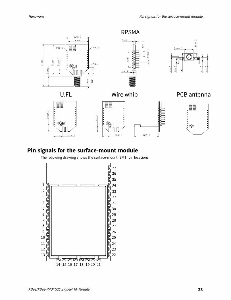
Mechanical drawingsThe following mechanical drawings of the XBee/XBee-PRO Zigbee RF Modules show all dimensions ininches. The first drawing shows the XBee/XBee‐PRO surface-mount model (antenna options notshown).
The drawings below show the XBee through-hole model
The drawings below show the XBee-PRO through-hole model.
Hardware Pin signals for the surface-mount module
XBee/XBee-PRO® S2C Zigbee® RF Module 23
Pin signals for the surface-mount moduleThe following drawing shows the surface-mount (SMT) pin locations.
Hardware Pin signals for the surface-mount module
XBee/XBee-PRO® S2C Zigbee® RF Module 24
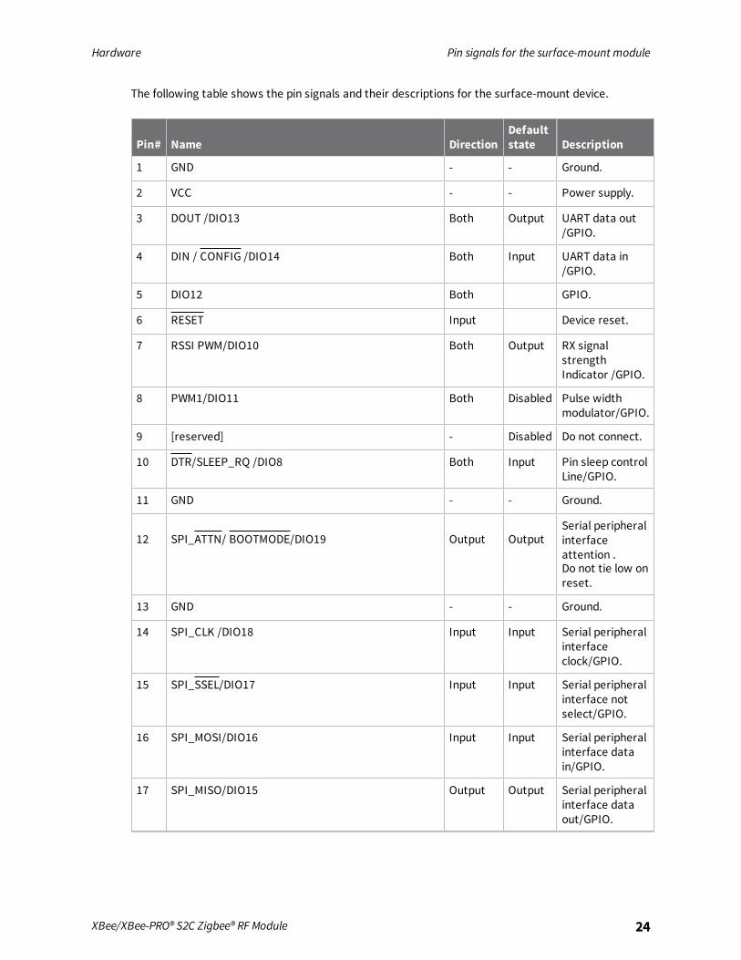
The following table shows the pin signals and their descriptions for the surface-mount device.
Pin# Name DirectionDefaultstate Description
1 GND - - Ground.
2 VCC - - Power supply.
3 DOUT /DIO13 Both Output UART data out/GPIO.
4 DIN / CONFIG /DIO14 Both Input UART data in/GPIO.
5 DIO12 Both GPIO.
6 RESET Input Device reset.
7 RSSI PWM/DIO10 Both Output RX signalstrengthIndicator /GPIO.
8 PWM1/DIO11 Both Disabled Pulse widthmodulator/GPIO.
9 [reserved] - Disabled Do not connect.
10 DTR/SLEEP_RQ /DIO8 Both Input Pin sleep controlLine/GPIO.
11 GND - - Ground.
12 SPI_ATTN/ BOOTMODE/DIO19 Output OutputSerial peripheralinterfaceattention .Do not tie low onreset.
13 GND - - Ground.
14 SPI_CLK /DIO18 Input Input Serial peripheralinterfaceclock/GPIO.
15 SPI_SSEL/DIO17 Input Input Serial peripheralinterface notselect/GPIO.
16 SPI_MOSI/DIO16 Input Input Serial peripheralinterface datain/GPIO.
17 SPI_MISO/DIO15 Output Output Serial peripheralinterface dataout/GPIO.

Hardware Pin signals for the surface-mount module
XBee/XBee-PRO® S2C Zigbee® RF Module 25
Pin# Name DirectionDefaultstate Description
18 [reserved]* - Disabled Do not connect.
19 [reserved]* - Disabled Do not connect.
20 [reserved]* - Disabled Do not connect.
21 [reserved]* - Disabled Do not connect.
22 GND - - Ground.
23 [reserved] - Disabled Do not connect.
24 DIO4 Both Disabled GPIO.
25 CTS/DIO7 Both Output Clear to sendflowcontrol/GPIO.
26 ON/SLEEP/DIO9 Both Output Device statusindicator/GPIO
27 VREF Input -
Not used forEM357. Used forprogrammablesecondaryprocessor. Forcompatibilitywith other XBeedevices, werecommendconnecting thispin to thevoltagereference ifanalog samplingis desired.Otherwise,connect to GND.
28 ASSOCIATE/DIO5 Both Output AssociateIndicator/GPIO.
29 RTS/DIO6 Both Input Request to sendflow control/GPIO.
30 AD3/DIO3 Both Disabled Analoginput/GPIO.
31 AD2/DIO2 Both Disabled Analoginput/GPIO
Hardware Pin signals for the through-hole module
XBee/XBee-PRO® S2C Zigbee® RF Module 26
Pin# Name DirectionDefaultstate Description
32 AD1/DIO1 Both Disabled Analoginput/GPIO.
33 AD0 /DIO0 Both Input Analog input /GPIO /Commissioningbutton.
34 [reserved] - Disabled Do not connect.
35 GND - - Ground.
36 RF Both - RF I/O for RFpad variant.
37 [reserved] - Disabled Do not connect.
Signal direction is specified with respect to the device.See Design notes for details on pin connections.* Refer to Writing custom firmware for instructions on using these pins if JTAG functions are needed.
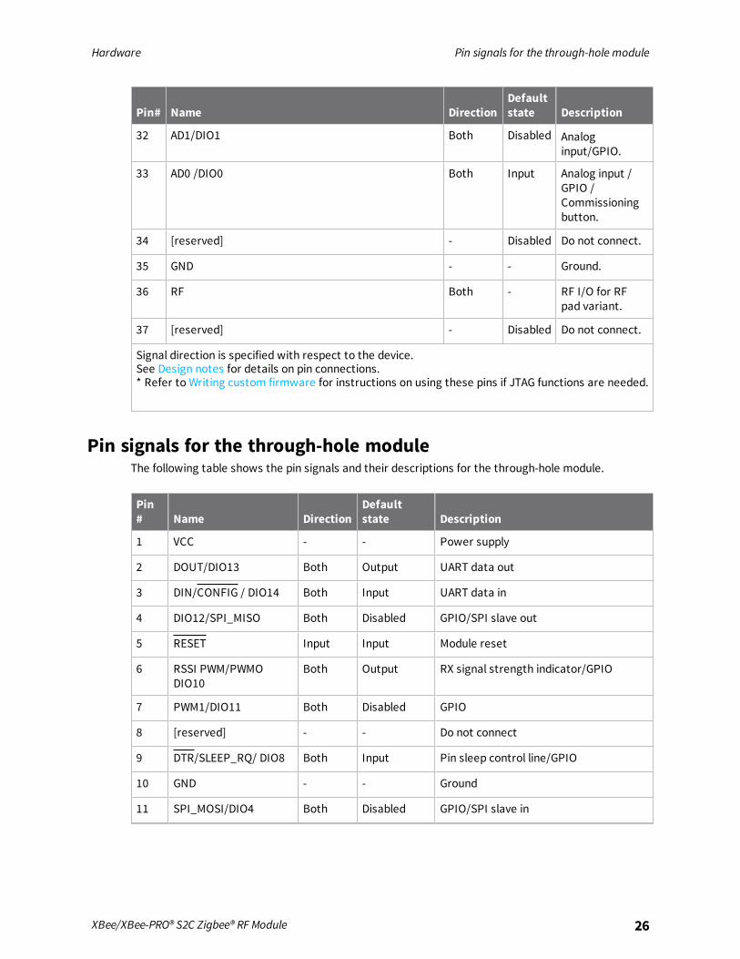
Pin signals for the through-hole moduleThe following table shows the pin signals and their descriptions for the through-hole module.
Pin# Name Direction
Defaultstate Description
1 VCC - - Power supply
2 DOUT/DIO13 Both Output UART data out
3 DIN/CONFIG / DIO14 Both Input UART data in
4 DIO12/SPI_MISO Both Disabled GPIO/SPI slave out
5 RESET Input Input Module reset
6 RSSI PWM/PWMODIO10
Both Output RX signal strength indicator/GPIO
7 PWM1/DIO11 Both Disabled GPIO
8 [reserved] - - Do not connect
9 DTR/SLEEP_RQ/ DIO8 Both Input Pin sleep control line/GPIO
10 GND - - Ground
11 SPI_MOSI/DIO4 Both Disabled GPIO/SPI slave in

Hardware EM357 pin mappings
XBee/XBee-PRO® S2C Zigbee® RF Module 27
Pin# Name Direction
Defaultstate Description
12 CTS/DIO7 Both Output Clear-to-send flow control/GPIO
13 ON_SLEEP/DIO9 Both Output Device status indicator/GPIO
14 VREF - - Not connected
15 ASSOCIATE/DIO5 Both Output Associate indicator/GPIO
16 RTS/DIO6 Both Input Request to send flow control/ GPIO
17 AD3/DIO3/SPI_SSEL Both Disabled Analog input/GPIO/SPI slave select
18 AD2 /DIO2/SPI_CLK Both Disabled Analog input/GPIO/SPI clock
19 AD1/DIO1/SPI_ATTN Both Disabled Analog input/GPIO/SPI attention
20 AD0/DIO0/CB Both Disabled Analog input/GPIO/ Commissioningbutton
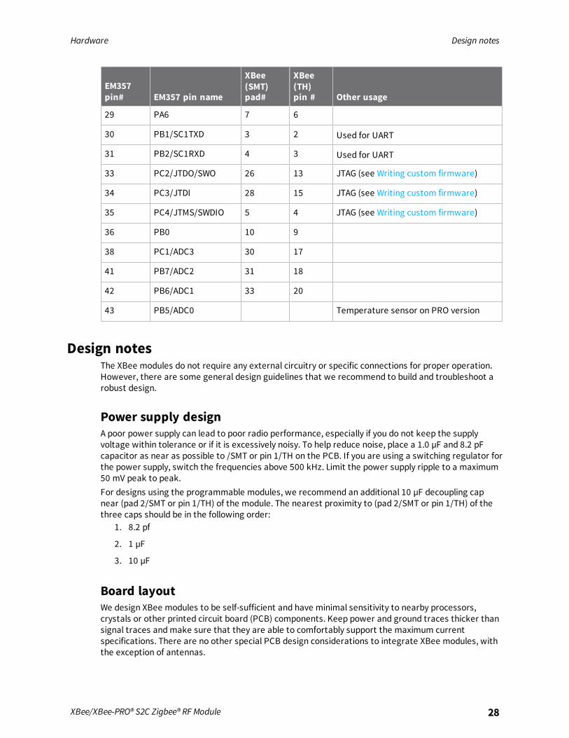
EM357 pin mappingsThe following table shows how the EM357 pins are used on the device.
Note Some lines may not go to the external device pins in the programmable secondary processorversion.
EM357pin# EM357 pin name
XBee(SMT)pad#
XBee(TH)pin # Other usage
12 RST 6 5 Programming
18 PA7 8 7
19 PB3 29 16 Used for UART
20 PB4 25 12 Used for UART
21 PA0/ SC2MOSI 16 11 Used for SPI
22 PA SC2MISO 17 4 Used for SPI
24 PA2/SC2SCLK 14 18 Used for SPI
25 PA3/SC2SSEL 15 17 Used for SPI
26 PA4/PTI_EN 32 19 OTA packet tracing
27 PA5/PTI_DATA/BOOTMODE
12 NA OTA packet tracing, force embeddedserial bootloader, and SPI attention line
Hardware Design notes
XBee/XBee-PRO® S2C Zigbee® RF Module 28
EM357pin# EM357 pin name
XBee(SMT)pad#
XBee(TH)pin # Other usage
29 PA6 7 6
30 PB1/SC1TXD 3 2 Used for UART
31 PB2/SC1RXD 4 3 Used for UART
33 PC2/JTDO/SWO 26 13 JTAG (see Writing custom firmware)
34 PC3/JTDI 28 15 JTAG (see Writing custom firmware)
35 PC4/JTMS/SWDIO 5 4 JTAG (see Writing custom firmware)
36 PB0 10 9
38 PC1/ADC3 30 17
41 PB7/ADC2 31 18
42 PB6/ADC1 33 20
43 PB5/ADC0 Temperature sensor on PRO version
Design notesThe XBee modules do not require any external circuitry or specific connections for proper operation.However, there are some general design guidelines that we recommend to build and troubleshoot arobust design.
Power supply designA poor power supply can lead to poor radio performance, especially if you do not keep the supplyvoltage within tolerance or if it is excessively noisy. To help reduce noise, place a 1.0 µF and 8.2 pFcapacitor as near as possible to /SMT or pin 1/TH on the PCB. If you are using a switching regulator forthe power supply, switch the frequencies above 500 kHz. Limit the power supply ripple to a maximum50 mV peak to peak.For designs using the programmable modules, we recommend an additional 10 µF decoupling capnear (pad 2/SMT or pin 1/TH) of the module. The nearest proximity to (pad 2/SMT or pin 1/TH) of thethree caps should be in the following order:
1. 8.2 pf
2. 1 µF
3. 10 µF
Board layoutWe design XBee modules to be self-sufficient and have minimal sensitivity to nearby processors,crystals or other printed circuit board (PCB) components. Keep power and ground traces thicker thansignal traces andmake sure that they are able to comfortably support the maximum currentspecifications. There are no other special PCB design considerations to integrate XBee modules, withthe exception of antennas.

Hardware Design notes
XBee/XBee-PRO® S2C Zigbee® RF Module 29
Antenna performanceAntenna location is important for optimal performance. The following suggestions help you achieveoptimal antenna performance. Point the antenna up vertically (upright). Antennas radiate and receivethe best signal perpendicular to the direction they point, so a vertical antenna's omnidirectionalradiation pattern is strongest across the horizon.Position the antennas away from metal objects whenever possible. Metal objects between thetransmitter and receiver can block the radiation path or reduce the transmission distance. Objectsthat are often overlooked include:
n Metal poles
n Metal studs
n Structure beams
n Concrete, which is usually reinforced with metal rods
If you place the device inside a metal enclosure, use an external antenna. Common objects that havemetal enclosures include:
n Vehicles
n Elevators
n Ventilation ducts
n Refrigerators
n Microwave ovens
n Batteries
n Tall electrolytic capacitors
Use the following additional guidelines for optimal antenna performance:
n Do not place XBee modules with the chip or integrated PCB antenna inside a metal enclosure.
n Do not place any ground planes or metal objects above or below the antenna.
n For the best results, mount the device at the edge of the host PCB. Ensure that the ground,power, and signal planes are vacant immediately below the antenna section.
n For more information, see Design notes for PCB antenna devices.
Recommended pin connectionsThe only required pin connections for two-way communication are VCC, GND, DOUT and DIN. Tosupport serial firmware updates, you must connect VCC, GND, DOUT, DIN, RTS, and DTR.Do not connect any pins that are not in use. Use the PR command to pull all inputs on the radio highwith internal pull-up resistors. Unused outputs do not require any specific treatment.For applications that need to ensure the lowest sleep current, never leave unconnected inputsfloating. Use internal or external pull-up or pull-down resistors, or set the unused I/O lines to outputs.You can connect other pins to external circuitry for convenience of operation including the AssociateLED pin (pin 15) and the Commissioning pin (pin 20). The Associate LED pin flashes differentlydepending on the state of the module, and a pushbutton attached to pin 20 can enable variousdeployment and troubleshooting functions without you sending UART commands. For moreinformation, see Commissioning pushbutton and associate LED.For analog sampling, attach the VREF pin (pin 14) to a voltage reference.

Hardware Design notes
XBee/XBee-PRO® S2C Zigbee® RF Module 30
Design notes for PCB antenna devicesPosition PCB antenna devices so there are no ground planes or metal objects above or below theantenna. For best results, do not place the device in a metal enclosure, as this may greatly reduce therange. Place the device at the edge of the PCB on which it is mounted. Make sure the ground, powerand signal planes are vacant immediately below the antenna section.The following drawings illustrate important recommendations when you are designing with PCBantenna devices. For optimal performance, do not mount the device on the RF pad footprint describedin the next section, because the footprint requires a ground plane within the PCB antenna keep outarea.
Surface-mount keepout area

Hardware Design notes
XBee/XBee-PRO® S2C Zigbee® RF Module 31
Through-hole keepout area
Notes1. We recommend non-metal enclosures. For metal enclosures, use an external antenna.
2. Keepmetal chassis or mounting structures in the keepout area at least 2.54 cm (1 in) from theantenna.
3. Maximize the distance between the antenna andmetal objects that might be mounted in thekeepout area.
4. These keepout area guidelines do not apply for wire whip antennas or external RF connectors.Wire whip antennas radiate best over the center of a ground plane.
Design notes for RF pad devicesThe RF pad is a soldered antenna connection. The RF signal travels from pin 33 on the device to theantenna through an RF trace transmission line on the PCB. Any additional components between thedevice and antenna violates modular certification. The controlled impedance for the RF trace is 50 Ω.We recommend using a microstrip trace, although you can also use a coplanar waveguide if you needmore isolation. A microstrip generally requires less area on the PCB than a coplanar waveguide. We do

Hardware Design notes
XBee/XBee-PRO® S2C Zigbee® RF Module 32
not recommend using a stripline because sending the signal to different PCB layers can introducematching and performance problems.Following good design practices is essential when implementing the RF trace on a PCB. Consider thefollowing points:
n Minimize the length of the trace by placing the RPSMA jack close to the device.
n Connect all of the grounds on the jack and the device to the ground planes directly or throughclosely placed vias.
n Space any ground fill on the top layer at least twice the distance d (in this case, at least 0.028")from the microstrip to minimize their interaction.
Additional considerations:n The top two layers of the PCB have a controlled thickness dielectric material in between.
n The second layer has a ground plane which runs underneath the entire RF pad area. Thisground plane is a distance d, the thickness of the dielectric, below the top layer.
n The top layer has an RF trace running from pin 33 of the device to the RF pin of the RPSMAconnector.
n The RF trace width determines the impedance of the transmission line with relation to theground plane. Many online tools can estimate this value, although you should consult the PCBmanufacturer for the exact width.
Implementing these design suggestions helps ensure that the RF pad device performs to itsspecifications.The following figures show a layout example of a host PCB that connects an RF pad device to a rightangle, through-hole RPSMA jack.

Hardware Design notes
XBee/XBee-PRO® S2C Zigbee® RF Module 33
Number Description
1 Maintain a distance of at least 2 d betweenmicrostrip and ground fill.
2 Device pin 33.
2 RF pad pin.
3 50 Ω microstrip trace.
4 RF connection of RPSMA jack.
The width in this example is approximately 0.025 in for a 50 Ω trace, assuming d = 0.014 in, and thatthe dielectric has a relative permittivity of 4.4. This trace width is a good fit with the device footprint's0.335" pad width.
Note We do not recommend using a trace wider than the pad width, and using a very narrow trace(under 0.010") can cause unwanted RF loss.
The following illustration shows PCB layer 2 of an example RF layout.

Hardware Design notes
XBee/XBee-PRO® S2C Zigbee® RF Module 34
Number Description
1 Use multiple vias to help eliminate ground variations.
2 Put a solid ground plane under RF trace to achieve the desired impedance.
Module operation for the programmable variantThe modules with the programmable option have a secondary processor with 32k of flash and 2k ofRAM. This allows module integrators to put custom code on the XBee module to fit their own uniqueneeds. The secondary processor intercepts the DIN, DOUT, RTS, CTS, and RESET lines to allow it to bein control of the data transmitted and received. All other lines are in parallel and can be controlled byeither the EM357 or the MC9SO8QE micro. See the following block diagram for details. TheProgrammable XBee SDK native APIs automatically handle pin use.For the secondary processor to sample with ADCs, the XBee VREF pin (27/SMT, 14/TH) must beconnected to a reference voltage.Digi provides a bootloader that can take care of programming the processor over-the-air or throughthe serial interface. This means that over-the-air updates can be supported through an XMODEMprotocol. The processor can also be programmed and debugged through a one wire interface BKGD(Pin 9/SMT, Pin 8/TH).

Programmable XBee SDK
The XBee Programmable module is equipped with a NXP MC9S08QE32 application processor. Thisapplication processor comes with a supplied bootloader. To interface your application code running onthis processor to the XBee Programmable module's supplied bootloader, use the Programmable XBeeSDK.To use the SDK, you must also download CodeWarrior. The download links are:
n CodeWarrior IDE: http://ftp1.digi.com/support/sampleapplications/40003004_B.exe
n Programmable XBee SDK: http://ftp1.digi.com/support/sampleapplications/40003003_D.exe
If these revisions change, search for the part number on Digi’s website. For example, search for40003003.Install the IDE first, and then install the SDK.The documentation for the Programmable XBee SDK is built into the SDK, so the Getting Started guideappears when you open CodeWarrior.
XBee/XBee-PRO® S2C Zigbee® RF Module 35

Programmable
XBeeSDK
Programmable
connections
XBee/XBee-PRO®S2CZigbee®RF
Module
36
Programmable connectionsThe following figure shows the programmable connections for the SMT.

Programmable
XBeeSDK
Programmable
connections
XBee/XBee-PRO®S2CZigbee®RF
Module
37
The following illustration shows the programmable connections for the TH Module.

Operation
Serial interface 39UART data flow 39SPI communications 40Serial buffers 41UART flow control 42Break control 43Serial interface protocols 43Modes 45
XBee/XBee-PRO® S2C Zigbee® RF Module 38
Operation Serial interface
XBee/XBee-PRO® S2C Zigbee® RF Module 39
Serial interfaceThe XBee/XBee-PRO Zigbee RF Module interface to a host device through a serial port. The device cancommunicate with any logic and voltage compatible UART, through a level translator to any serialdevice (for example, through a RS-232 or USB interface board), or through a SPI, as described in SPIcommunications.
Note Two Wire serial Interface (TWI) is also available, but not supported by Digi. For information onthe TWI, see the EM357 pin mappings.
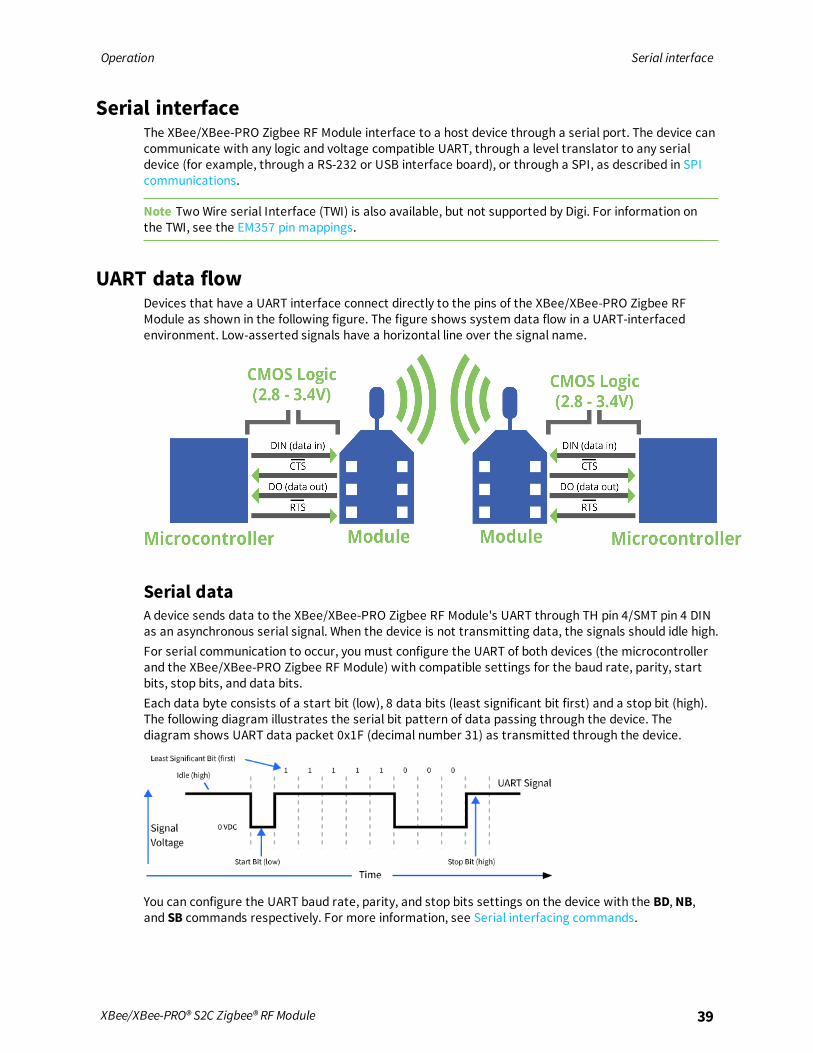
UART data flowDevices that have a UART interface connect directly to the pins of the XBee/XBee-PRO Zigbee RFModule as shown in the following figure. The figure shows system data flow in a UART-interfacedenvironment. Low-asserted signals have a horizontal line over the signal name.
Serial dataA device sends data to the XBee/XBee-PRO Zigbee RF Module's UART through TH pin 4/SMT pin 4 DINas an asynchronous serial signal. When the device is not transmitting data, the signals should idle high.For serial communication to occur, you must configure the UART of both devices (the microcontrollerand the XBee/XBee-PRO Zigbee RF Module) with compatible settings for the baud rate, parity, startbits, stop bits, and data bits.Each data byte consists of a start bit (low), 8 data bits (least significant bit first) and a stop bit (high).The following diagram illustrates the serial bit pattern of data passing through the device. Thediagram shows UART data packet 0x1F (decimal number 31) as transmitted through the device.
You can configure the UART baud rate, parity, and stop bits settings on the device with the BD, NB,and SB commands respectively. For more information, see Serial interfacing commands.

Operation SPI communications
XBee/XBee-PRO® S2C Zigbee® RF Module 40
SPI communicationsThe XBee/XBee-PRO Zigbee RF Module supports SPI communications in slave mode. Slave modereceives the clock signal and data from the master and returns data to the master. The followingtable shows the signals that the SPI port uses on the device.
Signal Function
SPI_MOSI (Master Out, Slave In) Inputs serial data from the master
SPI_MISO (Master In, Slave Out) Outputs serial data to the master
SPI_SCLK (Serial Clock) Clocks data transfers on MOSI and MISO
SPI_SSEL (Slave Select) Enables serial communication with the slave
The preceding four pins are standard for SPI. This devicd also supports an additional pin, which may beconfigured to alert the SPI master when it has data to send. This pin is called SPI_ATTN. If the mastermonitors this pin (through polling or interrupts), it can know when it needs to receive data from thedevice. SPI_ATTN asserts whenever it has data to send, and it remains asserted until all available datahas been shifted out to the SPImaster.In this mode:
n Data/clock rates of up to 5 Mb/s are possible.
n Data is most significant bit (MSB) first.
n Frame Format mode 0 is used. This means CPOL= 0 (idle clock is low) and CPHA = 0 (data issampled on the clock’s leading edge).
n The SPI port only supports API Mode (AP = 1).The following diagram shows the frame format mode 0 for SPI communications.
SPI operationWhen the master asserts the slave select (SPI_SSEL), the device drives SPI transmit data to theoutput pin (SPI_MISO), and receives SPI data from the input pin SPI_MOSI. The SPI_SSEL pin must beasserted to enable the transmit serializer to drive data to the output signal SPI_MISO. A rising edgeon SPI_SSEL resets the SPI slave shift registers.If the SPI_SCLK is present, the SPI_MISO line is always driven whether with or without the SPI_SSELline driven.

Operation Serial buffers
XBee/XBee-PRO® S2C Zigbee® RF Module 41
If the input buffer is empty, the SPI serializer transmits a busy token (0xFF). Otherwise, alltransactions on the SPI port use API operation. See API Operation for more information.The SPI slave controller must guarantee that there is time to move new transmit data from thetransmit buffer into the hardware serializer. To provide sufficient time, the SPI slave controller insertsa byte of padding at the start of every new string of transmit data. Whenever the transmit buffer isempty and the device places data into the transmit buffer, the SPI hardware inserts a byte of paddingonto the front of the transmission as if this byte were placed there by software.
Serial port selectionIn the default configuration both the UART and SPI ports are configured for serial port operation. Inthis case, serial data goes out the UART until the host device asserts the SPI_SSEL signal. Thereafterall serial communications operate only on the SPI interface until a reset occurs.If you enable only the UART, the XBee/XBee-PRO Zigbee RF Module uses only the UART, and ignoresthe SPI_SSEL.If you enable only the SPI, the XBee/XBee-PRO Zigbee RF Module uses only the SPI, and ignores UARTcommunications. If you hold DOUT low during boot, then the XBee/XBee-PRO Zigbee RF Module onlyuses the SPI.Once SPI is in use, do not attempt to apply changes (AC) which change the UART or SPI settings.Instead, use the following:
n 0x09 frames to reconfigure UART/SPI/other settings.
n WR to save the settings.
n FR to reset the XBee/XBee-PRO Zigbee RF Module and use the new configuration settings.
If neither serial port is enabled, then UART remains enabled, the device uses only the UART, and itignores SPI_SSEL.
Serial buffersThe XBee/XBee-PRO Zigbee RF Module maintains internal buffers to collect serial and RF data that itreceives. The serial receive buffer collects incoming serial characters and holds them until the devicecan process them. The serial transmit buffer collects the data it receives via the RF link until ittransmits that data out the serial port. The following figure shows the process of device bufferscollecting received serial data.

Operation UART flow control
XBee/XBee-PRO® S2C Zigbee® RF Module 42
Serial receive bufferWhen serial data enters the XBee/XBee-PRO Zigbee RF Module through the serial port, the devicestores the data in the serial receive buffer until it can be processed. Under certain conditions, thedevice may receive data when the serial receive buffer is already full. In that case, the device discardsthe data.The serial receive buffer becomes full when data is streaming into the serial port faster than it can beprocessed and sent over the air (OTA). While the speed of receiving the data on the serial port can bemuch faster than the speed of transmitting data for a short period, sustained operation in that modecauses the device to drop data due to running out of places to put the data. Some things that maydelay over the air transmissions are address discovery, route discovery, and retransmissions.Processing received RF data can also take away time and resources for processing incoming serialdata.If the UART is the serial port and you enable the CTS flow control, the device alerts the external datasource when the receive buffer is almost full. The host delays sending data to the device until themodule asserts CTS again, allowing more data to come in.If the SPI is the serial port, no hardware flow control is available. It is your responsibility to ensurethat the receive buffer does not overflow. One reliable strategy is to wait for a TX_STATUS responseafter each frame sent to ensure that the device has had time to process it.
Serial transmit bufferWhen the device receives RF data, it moves the data into the serial transmit buffer and sends it outthe UART or SPI port. If the serial transmit buffer becomes full and the system buffers are also full,then it drops the entire RF data packet. Whenever the device receives data faster than it can processand transmit the data out the serial port, there is a potential of dropping data.In situations where the serial transmit buffer may become full, resulting in dropped RF packets:
1. If the RF data rate is set higher than the interface data rate of the device, the device mayreceive data faster than it can send the data to the host. Even occasional transmissions from alarge number of devices can quickly accumulate and overflow the transmit buffer.
2. If the host does not allow the device to transmit data out from the serial transmit buffer due tobeing held off by hardware flow control.
UART flow controlYou can use the RTS and CTS pins to provide RTS and/or CTS flow control. CTS flow control provides anindication to the host to stop sending serial data to the device. RTS flow control allows the host tosignal the device to not send data in the serial transmit buffer out the UART. To enable RTS/CTS flowcontrol, use the D6 and D7 commands.
Note Serial port flow control is not possible when using the SPI port.
CTS flow controlIf you enable CTS flow control (D7 command), when the serial receive buffer is 17 bytes away frombeing full, the device de-asserts CTS (sets it high) to signal to the host device to stop sending serialdata. The device reasserts CTS after the serial receive buffer has 34 bytes of space.In either case, CTS is not re-asserted until the serial receive buffer has FT-17 or less bytes in use.

Operation Break control
XBee/XBee-PRO® S2C Zigbee® RF Module 43
RTS flow controlIf you send the D6 command to enable RTS flow control, the device does not send data in the serialtransmit buffer out the DOUT pin as long as RTS is de-asserted (set high). Do not de-assert RTS forlong periods of time or the serial transmit buffer will fill. If the device receives an RF data packet andthe serial transmit buffer does not have enough space for all of the data bytes, it discards the entireRF data packet.If the device sends data out the UART when RTS is de-asserted (set high) the device could send up tofive characters out the UART port after RTS is de-asserted.
Break controlIf a serial break (DIN held low) signal is sent for over five seconds, the device resets, and it boots intoCommandmode with default baud settings (9600 baud). If either P3 or P4 are not enabled, this breakfunction is disabled.
Serial interface protocolsThe XBee/XBee-PRO Zigbee RF Module supports both Transparent and Application ProgrammingInterface (API) serial interfaces.
Transparent operating modeWhen operating in Transparent mode, the devices act as a serial line replacement. The device queuesup all UART or SPI data received through the DIN or MOSI pin for RF transmission. When RF data isreceived, the device sends the data out through the serial port. Use the Commandmode interface toconfigure the device configuration parameters.
Note Transparent operation is not available when using SPI.
The device buffers data in the serial receive buffer and packetizes and transmits the data when itreceives the following:
n No serial characters for the amount of time determined by the RO (Packetization Timeout)parameter. If RO = 0, packetization begins when the device received a character.
n Command Mode Sequence (GT + CC + GT). Any character buffered in the serial receive bufferbefore the device transmits the sequence.
n Maximum number of characters that fit in an RF packet.
API operating modeAPI operating mode is an alternative to Transparent operating mode. The frame-based API extendsthe level to which a host application can interact with the networking capabilities of the device. Whenin API mode, the device contains all data entering and leaving in frames that define operations orevents within the device.The API provides alternative means of configuring devices and routing data at the host applicationlayer. A host application can send data frames to the device that contain address and payloadinformation instead of using Commandmode to modify addresses. The device sends data frames tothe application containing status packets, as well as source and payload information from receiveddata packets.The API operation option facilitates many operations such as:
Operation Serial interface protocols
XBee/XBee-PRO® S2C Zigbee® RF Module 44
n Transmitting data to multiple destinations without entering Command Mode
n Receive success/failure status of each transmitted RF packet
n Identify the source address of each received packet
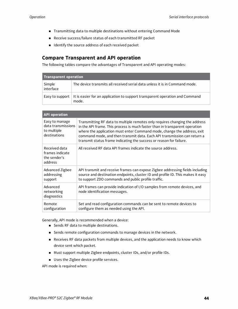
Compare Transparent and API operationThe following tables compare the advantages of Transparent and API operating modes:
Transparent operation
Simpleinterface
The device transmits all received serial data unless it is in Commandmode.
Easy to support It is easier for an application to support transparent operation and Commandmode.
API operation
Easy to manage data transmissionsto multipledestinations
Transmitting RF data to multiple remotes only requires changing the addressin the API frame. This process is much faster than in transparent operationwhere the application must enter Commandmode, change the address, exitcommandmode, and then transmit data. Each API transmission can return atransmit status frame indicating the success or reason for failure.
Received dataframes indicatethe sender'saddress
All received RF data API frames indicate the source address.
Advanced Zigbeeaddressingsupport
API transmit and receive frames can expose Zigbee addressing fields includingsource and destination endpoints, cluster ID and profile ID. This makes it easyto support ZDO commands and public profile traffic.
Advancednetworkingdiagnostics
API frames can provide indication of I/O samples from remote devices, andnode identification messages.
Remoteconfiguration
Set and read configuration commands can be sent to remote devices toconfigure them as needed using the API.
Generally, API mode is recommended when a device:n Sends RF data to multiple destinations.
n Sends remote configuration commands to manage devices in the network.
n Receives RF data packets from multiple devices, and the application needs to know whichdevice sent which packet.
n Must support multiple Zigbee endpoints, cluster IDs, and/or profile IDs.
n Uses the Zigbee device profile services.
API mode is required when:

Operation Modes
XBee/XBee-PRO® S2C Zigbee® RF Module 45
n Using Smart Energy firmware.
n Using SPI for the serial port.
n Receiving I/O samples from remote devices.
n Using source routing.
If the above conditions do not apply (for example a sensor node, router, or a simple application), thenTransparent operating mode might be suitable. It is acceptable to use a mixture of devices runningAPI mode and Transparent mode in a network.
ModesThe XBee/XBee-PRO Zigbee RF Module is in Receive Mode when it is not transmitting data. The deviceshifts into the other modes of operation under the following conditions:
n Transmit mode (Serial data in the serial receive buffer is ready to be packetized)
n Sleepmode
n Command Mode (Commandmode sequence is issued)

Operation Modes
XBee/XBee-PRO® S2C Zigbee® RF Module 46
Idle modeWhen not receiving or transmitting data, the device is in Idle mode. During Idle mode, the devicelistens for valid data on both the RF and serial ports.The device shifts into the other modes of operation under the following conditions:
n Transmit mode (serial data in the serial receive buffer is ready to be packetized).
n Receive mode (valid RF data received through the antenna).
n Commandmode (Commandmode sequence issued, not available with Smart Energy softwareor when using the SPI port).
Transmit modePrior to transmitting data, the module ensures that a 16-bit network address and route to thedestination node have been established.If you do not know the destination 16-bit network address known, network address discovery takesplace. If you do not know the a route is not known, route discovery takes place for the purpose ofestablishing a route to the destination node. If a device with a matching network address is notdiscovered, it discards the packet. The device transmits the data once a route is established. If routediscovery fails to establish a route, the device discards the packet. The following diagram shows theTransmit Mode sequence.
When Zigbee data is transmitted from one node to another, the destination node transmits anetwork-level acknowledgment back across the established route to the source node. Thisacknowledgment packet indicates to the source node that the destination node received the datapacket. If the source node does not receive a network acknowledgment, it retransmits the data.It is possible in rare circumstances for the destination to receive a data packet, but for the source tonot receive the network acknowledgment. In this case, the source retransmits the data, which cancause the destination to receive the same data packet multiple times. The XBee modules do not filterout duplicate packets. We recommend that the application includes provisions to address this issue.For more information, see Transmission, addressing, and routing.

Operation Modes
XBee/XBee-PRO® S2C Zigbee® RF Module 47
Receive modeThis is the default mode for the XBee/XBee-PRO Zigbee RF Module. The device is in Receive modewhen it is not transmitting data. If a destination node receives a valid RF packet, the destination nodetransfers the data to its serial transmit buffer.
Command modeCommandmode is a state in which the firmware interprets incoming characters as commands. It isonly available over the UART when not using the Smart Energy firmware. API Operation describes analternate means for configuring devices that is available with the SPI and with Smart Energy, as wellas over the UART with Zigbee code.
Enter Command modeTo get a device to switch into this mode, you must issue the following sequence: +++ and observeguard times before and after the command character.The default sequence to transition to Commandmode is:
n No characters sent for one second [GT (Guard Times) parameter = 0x3E8].
n Three plus characters (+++) input within one second [CC (Command Sequence Character)parameter = 0x2B.].
n No characters sent for one second [GT (Guard Times) parameter = 0x3E8].
When you send the Commandmode sequence, the device sends OK out the UART pin. The device maydelay sending the OK if it has not transmitted all of the serial data it received.When the device is in Commandmode, it starts the Commandmode timer (CT command) and canreceive AT commands on the UART port.You can customize the command character, the guard times and the timeout in the device’sconfiguration settings. For more information, see CC (Command Character), CT command and GTcommand.
TroubleshootingFailure to enter Commandmode is often due to baud rate mismatch. Ensure that the baud rate of theconnection matches the baud rate of the device. By default, the BD parameter = 3 (9600 b/s).
Send AT commandsOnce the device enters Commandmode, use the syntax in the following figure to send AT commands.Every AT command starts with the letters AT, which stands for "attention." The AT is followed by twocharacters that indicate which command is being issued, then by some optional configuration values.To read a parameter value stored in the device’s register, omit the parameter field.
The preceding example changes the device's destination address (Low) to 0x1F.

Operation Modes
XBee/XBee-PRO® S2C Zigbee® RF Module 48
To store the new value to non-volatile (long term) memory, send the WR (Write) command. This allowsparameter values that you modify to persist in the device's registry after a reset. Otherwise, thedevice restores parameters to the previous values after a reset.
Multiple AT commandsYou can sendmultiple AT commands at a time when they are separated by a comma in Commandmode; for example, ATSH,SL.
Parameter formatRefer to the list of AT commands for the format of individual AT command parameters. Valid formatsfor hexidecimal values include with or without a leading 0x for example FFFF or 0xFFFF.
Response to AT commandsWhen you send a command to the device, the device parses and runs the command. If the commandruns successfully, the device returns anOKmessage. If the command errors, the device returns anERRORmessage.
Apply command changesAny changes you make to the configuration command registers using AT commands do not take effectuntil you apply the changes. For example, if you send the BD command to change the baud rate, theactual baud rate does not change until you apply the changes. To apply changes:
1. Send the AC (Apply Changes) command.or:
2. Exit Commandmode.
Exit Command mode1. Send the CN (Exit Command Mode) command followed by a carriage return.
or:
2. If the device does not receive any valid AT commands within the time specified by CT(Command Mode Timeout), it returns to Idle Mode.
For an example of programming the device using AT Commands and descriptions of each configurableparameter, see AT commands.
Sleep modeSleepmodes allow the device to enter states of low power consumption when not in use. TheXBee/XBee-PRO Zigbee RF Module supports both pin sleep (Sleepmode entered on pin transition) andcyclic sleep (device sleeps for a fixed time).Sleepmodes are discussed in detail in Manage End Devices.Sleepmodes allow the device to enter states of low power consumption when not in use. The device isalmost completely off during sleep, and is incapable of sending or receiving data until it wakes up.XBee devices support pin sleep, where the device enters sleepmode upon pin transition, and cyclicsleep, where the device sleeps for a fixed time.For more information, see Manage End Devices.
Zigbee networks
About the Zigbee specification 50Definitions 50Zigbee stack layers 52Zigbee networking concepts 53Zigbee application layers: in depth 56Zigbee coordinator operation 57Router operation 62End device operation 68Zigbee channel scanning 72
XBee/XBee-PRO® S2C Zigbee® RF Module 49

Zigbee networks About the Zigbee specification
XBee/XBee-PRO® S2C Zigbee® RF Module 50
About the Zigbee specificationZigbee is an open global standard for low-power, low-cost, low-data-rate, wireless mesh networkingbased on the IEEE 802.15.4 standard. It represents a network layer above the 802.15.4 layers tosupport advancedmesh routing capabilities. The Zigbee specification is developed by a consortium ofcompanies that make up the Zigbee Alliance. The alliance is made up of over 300 members, includingsemiconductor, module, stack, and software developers. For more information, seehttp://www.zigbee.org/.
DefinitionsThis section provides definitions of the Zigbee note types and protocols.
Zigbee node types
Node Description
Coordinator A node that has the unique function of forming a network. The coordinator isresponsible for establishing the operating channel and PAN ID for an entire network.Once established, the coordinator can form a network by allowing routers and enddevices to join. Once the network is formed, the coordinator functions like a router. Itcan participate in routing packets and be a source or destination for data packets.
n One coordinator per PAN
n Establishes/Organizes PAN
n Can route data packets to/from other nodes
n Can be a data packet source and destination
n Mains-poweredRefer to Zigbee coordinator operation for more information.
Router A node that creates/maintains network information and uses this information todetermine the best route for a data packet. A router must join a network before it canallow other routers and end devices to join. A router can participate in routing packetsand is intended to be a mains-powered node.
n Several routers can operate in one PAN
n Can route data packets to/from other nodes
n Can be a data packet source and destination
n Mains-poweredRefer to Router operation for more information.

Zigbee networks Definitions
XBee/XBee-PRO® S2C Zigbee® RF Module 51
Node Description
End device End devices must always interact with their parent to receive or transmit data. (Seethe "Joining" in the following table.) They are intended to sleep periodically andtherefore have no routing capacity. An end device can be a source or destination fordata packets but cannot route packets. End devices can be battery-powered and offerlow-power operation.
n Several end devices can operate in one PAN
n Can be a data packet source and destination
n All messages are relayed through a coordinator or router
n Lower power modes
Zigbee protocol
Protocol Description
PAN Personal Area Network - A data communication network that includes acoordinator and one or more routers/end devices.
Joining The process of a node becoming part of a Zigbee PAN. A node becomes part of anetwork by joining to a coordinator or a router (that has previously joined tothe network). During the process of joining, the node that allowed joining (theparent) assigns a 16-bit address to the joining node (the child).
Network address The 16-bit address assigned to a node after it has joined to another node. Thecoordinator always has a network address of 0.
Operating channel The frequency selected for data communications between nodes. Theoperating channel is selected by the coordinator on power-up.
Energy scan A scan of RF channels that detects the amount of energy present on theselected channels. The coordinator uses the energy scan to determine theoperating channel.
Route request Broadcast transmission sent by a coordinator or router throughout thenetwork in attempt to establish a route to a destination node.
Route reply Unicast transmission sent back to the originator of the route request. It isinitiated by a node when it receives a route request packet and its addressmatches the Destination Address in the route request packet.
Route reply The process of establishing a route to a destination node when one does notexist in the Routing Table. It is based on the Ad-hoc On-demand Distance Vectorrouting (AODV) protocol.
Zigbee stack Zigbee is a published specification set of high-level communication protocols foruse with small, low- power modules. The Zigbee stack provides a layer ofnetwork functionality on top of the 802.15.4 specification.For example, the mesh and routing capabilities available to Zigbee solutions areabsent in the 802.15.4 protocol.

Zigbee networks Zigbee stack layers
XBee/XBee-PRO® S2C Zigbee® RF Module 52
Zigbee stack layersMost network protocols use the concept of layers to separate different components and functionsinto independent modules that can be assembled in different ways.Zigbee is built on the Physical (PHY) layer and Medium Access Control (MAC) sub-layer defined in theIEEE 802.15.4 standard. These layers handle low-level network operations such as addressing andmessage transmission/reception.The Zigbee specification defines the Network (NWK) layer and the framework for the application (APL)layer. The Network layer takes care of the network structure, routing, and security. The applicationlayer framework consists of the Application Support sub-layer (APS), the Zigbee device objects (ZDO)and user-defined applications that give the device its specific functionality.
This table describes the Zigbee layers.
Zigbee layer Descriptions
PHY Defines the physical operation of the Zigbee device including receive sensitivity,channel rejection, output power, number of channels, chip modulation, andtransmission rate specifications. Most Zigbee applications operate on the 2.4 GHzISM band at a 250 kb/s data rate. See the IEEE 802.15.4 specification for details.
MAC Manages RF data transactions between neighboring devices (point to point). TheMAC includes services such as transmission retry and acknowledgmentmanagement, and collision avoidance techniques (CSMA-CA).
Network Adds routing capabilities that allows RF data packets to traverse multiple devices(multiple hops) to route data from source to destination (peer to peer).

Zigbee networks Zigbee networking concepts
XBee/XBee-PRO® S2C Zigbee® RF Module 53
Zigbee layer Descriptions
APS (AF) Application layer that defines various addressing objects including profiles, clusters,and endpoints.
ZDO Application layer that provides device and service discovery features and advancednetwork management capabilities.
Zigbee networking concepts
Device typesZigbee defines three different device types: coordinator, router, and end device.
CoordinatorZigbee networks may only have a single coordinator device. This device:
n Starts the network, selecting the channel and PAN ID (both 64-bit and 16-bit).
n Buffers wireless data packets for sleeping end device children.
n Manages the other functions that define the network, secure it, and keep it healthy.
n Cannot sleep; the coordinator must be powered on all the time.
RouterA router is a full-featured Zigbee node. This device:
n Can join existing networks and send, receive, and route information. Routing involves acting asa messenger for communications between other devices that are too far apart to conveyinformation on their own.
n Can buffer wireless data packets for sleeping end device children. Can allow other routers andend devices to join the network.
n Cannot sleep; router(s) must be powered on all the time.
n May have multiple router devices in a network.
End deviceAn end device is essentially a reduced version of a router. This device:
n Can join existing networks and send and receive information, but cannot act as messengerbetween any other devices.
n Cannot allow other devices to join the network.
n Uses less expensive hardware and can power itself down intermittently, saving energy bytemporarily entering a non responsive sleepmode.
n Always needs a router or the coordinator to be its parent device. The parent helps end devicesjoin the network, and stores messages for them when they are asleep.
Zigbee networks may have any number of end devices. In fact, a network can be composed of onecoordinator, multiple end devices, and zero routers.

Zigbee networks Zigbee networking concepts
XBee/XBee-PRO® S2C Zigbee® RF Module 54
The following diagram shows a generic Zigbee network.
Note Each Zigbee network must be formed by one, and only one, coordinator and at least one otherdevice (router or end device).
In Zigbee networks, the coordinator must select a PAN ID (64-bit and 16-bit) and channel to start anetwork. After that, it behaves essentially like a router. The coordinator and routers can allow otherdevices to join the network and can route data.After an end device joins a router or coordinator, it must be able to transmit or receive RF datathrough that router or coordinator. The router or coordinator that allowed an end device to joinbecomes the “parent” of the end device. Since the end device can sleep, the parent must be able tobuffer or retain incoming data packets destined for the end device until the end device is able to wakeand receive the data.A device can only operate as one of the three device types. The device type is selected byconfiguration rather than by firmware image as was the case on earlier hardware platforms.By default, the device operates as a router. To select coordinator operation, set CE to 1. To select enddevice operation, set SM to a non-zero value. To select router operation, both CE and SMmust be 0.If a device is a coordinator and it needs to be changed into an end device, you must set CE to 0 first. Ifnot, the SM configuration will conflict with the CE configuration. Likewise, to change an end device intoa coordinator, you must change it into a router first.Another complication is that default parameters do not always work well for a coordinator.For example:
n DH/DL is 0 by default, which allows routers and end devices to send transparent data to thecoordinator when they first come up. If DH/DL is not changed from the default value when thedevice is changed to a coordinator, then the device sends data to itself, causing characters tobe echoed back to the screen as they are typed. Since this is probably not the desiredoperation, set DH/DL to the broadcast address or some specific unicast address when thedevice is changed to a coordinator.
n Another example is EO for smart energy builds. Set this value to 08 for routers and end devicesand 02 for the coordinator to designate it as the trust center. Therefore, if usingauthentication, which is the normal case for Smart Energy builds, change EO from 02 to 08when CE is set to 1.

Zigbee networks Zigbee networking concepts
XBee/XBee-PRO® S2C Zigbee® RF Module 55
n Another example is EO for Zigbee builds. By default the value is 0x00. But if EO and EE are setto 0x01 on all radios in a network, then the network key will be sent in the clear (unencrypted)at association time. This may be a useful setting in development environments, but isdiscouraged for security reasons for product deployment.
In general, it is your responsibility to ensure that parameters are set to be compatible with the newdevice type when changing device types.
PAN IDZigbee networks are called personal area networks (PANs). Each network is defined with a uniquePAN identifier (PAN ID), which is common among all devices of the same network. Zigbee devices areeither preconfigured with a PAN ID to join, or they can discover nearby networks and select a PAN IDto join.Zigbee supports both a 64-bit and a 16-bit PAN ID. Both PAN IDs are used to uniquely identify anetwork. Devices on the same Zigbee network must share the same 64-bit and 16-bit PAN IDs. Ifmultiple Zigbee networks are operating within range of each other, each should have unique PAN IDs.
16-bit PAN IDThe 16-bit PAN ID is used as a MAC layer addressing field in all RF data transmissions between devicesin a network. However, due to the limited addressing space of the 16-bit PAN ID (65,535 possibilities),there is a possibility that multiple Zigbee networks (within range of each other) could use the same16-bit PAN ID. To resolve potential 16-bit PAN ID conflicts, the Zigbee Alliance created a 64-bit PAN ID.
64-bit PAN IDThe 64-bit PAN ID (also called the extended PAN ID), is intended to be a unique, non-duplicated value.When a coordinator starts a network, it can either start a network on a preconfigured 64-bit PAN ID,or it can select a random 64-bit PAN ID. Devices use a 64-bit PAN ID during joining; if a device has apreconfigured 64-bit PAN ID, it will only join a network with the same 64-bit PAN ID. Otherwise, adevice could join any detected PAN and inherit the PAN ID from the network when it joins. All Zigbeebeacons include the 64-bit PAN ID and is used in 16- bit PAN ID conflict resolution.
Routers and end devicesRouters and end devices are typically configured to join a network with any 16-bit PAN ID as long asthe 64-bit PAN ID is valid. Coordinators typically select a random 16-bit PAN ID for their network.Since the 16-bit PAN ID only allows up to 65,535 unique values, and the device randomly selects the16-bit PAN ID, provisions exist in Zigbee to detect if two networks (with different 64-bit PAN IDs) areoperating on the same 16- bit PAN ID. If the device detects a conflict, the Zigbee stack can performPAN ID conflict resolution to change the 16- bit PAN ID of the network in order to resolve the conflict.See the Zigbee specification for details.Zigbee routers and end devices should be configured with the 64-bit PAN ID of the network they wantto join, and they typically acquire the 16-bit PAN ID when they join a network.Only enable CE on one device to avoid PAN ID conflicts and network problems.
Operating channelsZigbee uses direct-sequence spread spectrum modulation and operates on a fixed channel. The802.15.4 PHY defines 16 operating channels (channels 11 to 26) in the 2.4 GHz frequency band. XBeemodules support all 16 channels.

Zigbee networks Zigbee application layers: in depth
XBee/XBee-PRO® S2C Zigbee® RF Module 56
Zigbee application layers: in depthThe following topics provide a more in-depth look at the Zigbee application stack layers (APS, ZDO)including a discussion on Zigbee endpoints, clusters, and profiles. Much of the material in these topicsdiscuss details of the Zigbee stack that are not required in many cases.Read these topics if:
n The XBee/XBee-PRO Zigbee RF Module may talk to non-Digi Zigbee devices.
n The XBee/XBee-PRO Zigbee RF Module requires network management and discoverycapabilities of the ZDO layer.
n The XBee/XBee-PRO Zigbee RF Module needs to operate in a public application profile (forexample, smart energy, home automation, and so on).
Skip these topics if:n The XBee/XBee-PRO Zigbee RF Module does not need to interoperate or talk to non-Digi
Zigbee devices.
n The XBee/XBee-PRO Zigbee RF Module simply needs to send data between devices.
Application Support Sublayer (APS)The APS layer in Zigbee adds support for application profiles, cluster IDs, and endpoints.
Application profilesApplication profiles specify various device descriptions including required functionality for variousdevices. The collection of device descriptions forms an application profile. Application profiles aredefined as Public or Private profiles. Private profiles are defined by a manufacturer whereas publicprofiles are defined, developed, andmaintained by the Zigbee Alliance. Each application profile has aunique profile identifier assigned by the Zigbee Alliance.Examples of public profiles include:
n Home automation
n Smart Energy
n Commercial building automation
For example, the Smart Energy profile defines various device types including an energy service portal,load controller, thermostat, in-home display, and so on. The Smart Energy profile defines requiredfunctionality for each device type. For example, a load controller must respond to a defined commandto turn a load on or off. By defining standard communication protocols and device functionality, publicprofiles allow interoperable Zigbee solutions to be developed by independent manufacturers.Digi XBee Zigbee firmware operates on a private profile called the Digi Drop-In Networking profile.However, in many cases the XBee/XBee-PRO Zigbee RF Module can use API mode to talk to devices inpublic profiles or non-Digi private profiles. For more information, see API Operation.
ClustersA cluster is an application message type defined within a profile. You can use clusters to specify aunique function, service, or action. The following examples are some clusters defined in the homeautomation profile:
Zigbee networks Zigbee coordinator operation
XBee/XBee-PRO® S2C Zigbee® RF Module 57
n On/Off - Used to switch devices on or off (lights, thermostats, and so forth)
n Level Control - Used to control devices that can be set to a level between on and off
n Color Control - Controls the color of color capable devices
Each cluster has an associated 2-byte cluster identifier (cluster ID). All application transmissionsinclude the cluster ID. Clusters often have associated request and response messages. For example, asmart energy gateway (service portal) might send a load control event to a load controller in order toschedule turning on or off an appliance. Upon executing the event, the load controller sends a loadcontrol report message back to the gateway.Devices that operate in an application profile (private or public) must respond correctly to all requiredclusters. For example, a light switch that operates in the home automation public profile mustcorrectly implement the On/Off and other required clusters in order to interoperate with other homeautomation devices. The Zigbee Alliance has defined a Zigbee cluster library (ZCL) that containsdefinitions or various general use clusters that could be implemented in any profile.XBee modules implement various clusters in the Digi private profile. You can also use the API to sendor receive messages on any cluster ID (and profile ID or endpoint). For more information, see ExplicitRx Indicator frame - 0x91.
EndpointsThe APS layer includes supports for endpoints. An endpoint can be thought of as a running application,similar to a TCP/IP port. A single device can support one or more endpoints. A 1- byte value identifieseach application endpoint, ranging from 1 to 240. Each defined endpoint on a device is tied to anapplication profile. A device could, for example, implement one endpoint that supports a Smart Energyload controller, and another endpoint that supports other functionality on a private profile.No TX Status frame is generated for API frames that have both 0xE6 as the destination endpoint and0xC105 as the Profile ID as this combination is reserved for internal XBee/XBee-PRO Zigbee RFModule operations.
Zigbee device profileProfile ID 0x0000 is reserved for the Zigbee device profile. This profile is implemented on all Zigbeedevices. Device Profile defines many device and service discovery features and network managementcapabilities. Endpoint 0 is a reserved endpoint that supports the Zigbee device profile. This endpoint iscalled the Zigbee device objects (ZDO) endpoint.
Zigbee device objectsThe ZDO (endpoint 0) supports the discovery andmanagement capabilities of the Zigbee deviceprofile. See the Zigbee specification for a complete listing of all ZDP services. Each service has anassociated cluster ID.The XBee Zigbee firmware allows applications to easily send ZDO messages to devices in the networkusing the API. For more information, see ZDO transmissions.
Zigbee coordinator operation
Form a networkThe coordinator is responsible for selecting the channel, PAN ID, security policy, and stack profile for anetwork. Since a coordinator is the only device type that can start a network, each Zigbee networkmust have one coordinator. After the coordinator has started a network, it can allow new devices tojoin the network. It can also route data packets and communicate with other devices on the network.

Zigbee networks Zigbee coordinator operation
XBee/XBee-PRO® S2C Zigbee® RF Module 58
To ensure the coordinator starts on a good channel and unused PAN ID, the coordinator performs aseries of scans to discover any RF activity on different channels (energy scan) and to discover anynearby operating PANs (PAN scan). The process for selecting the channel and PAN ID are described inthe following topics.
Security policyThe security policy determines which devices are allowed to join the network, and which device(s) canauthenticate joining devices. See Zigbee security for a detailed discussion of various security policies.
Channel selectionWhen starting a network, the coordinator must select a “good” channel for the network to operateon. To do this, it performs an energy scan onmultiple channels (that is, frequencies) to detect energylevels on each channel. The coordinator removes channels with excessive energy levels from its list ofpotential channels to start on.
PAN ID selectionAfter completing the energy scan, the coordinator scans its list of potential channels (remainingchannels after the energy scan) to obtain a list of neighboring PANs. To do this, the coordinator sendsa beacon request (broadcast) transmission on each potential channel. All nearby coordinators androuters that have already joined a Zigbee network respond to the beacon request by sending abeacon back to the coordinator. The beacon contains information about which PAN the device is on,including the PAN identifiers (16-bit and 64-bit). This scan (collecting beacons on the potentialchannels) is typically called an active scan or PAN scan.After the coordinator completes the channel and PAN scan, it selects a random channel and unused16-bit PAN ID to start on.
Persistent dataOnce a coordinator starts a network, it retains the following information through power cycle or resetevents:
n PAN ID
n Operating channel
n Security policy and frame counter value
n Child table (end device children that are joined to the coordinator)
n Binding table
n Group table
The coordinator retains this information indefinitely until it leaves the network. When the coordinatorleaves a network and starts a new network, the previous PAN ID, operating channel, link key table,and child table data are lost.
Coordinator startupThe following table provides the network formation commands that the coordinator uses to form anetwork.

Zigbee networks Zigbee coordinator operation
XBee/XBee-PRO® S2C Zigbee® RF Module 59
Command Description
ID Used to determine the 64-bit PAN ID. If set to 0 (default), a random 64-bit PAN ID willbe selected.
SC Determines the scan channels bitmask (up to 16 channels) used by the coordinatorwhen forming a network. The coordinator will perform an energy scan on all enabled SCchannels. It will then perform a PAN ID scan.
SD Set the scan duration, or time that the router will listen for beacons on each channel.
ZS Set the Zigbee stack profile for the network.
EE Enable or disable security in the network.
NK Set the network security key for the network. If set to 0 (default), the coordinator usesa random network security key.
KY Set the trust center link key for the network. If set to 0 (default), the coordinator usesa random link key.
EO Set the security policy for the network.
Configuration changes delay the start of network formation for five seconds after the last change.Once the coordinator starts a network, the network configuration settings and child table datapersist through power cycles as mentioned in Persistent data.When the coordinator has successfully started a network, it:
n Allows other devices to join the network for a time; see NJ (Node Join Time)
n Sets AI = 0
n Starts blinking the Associate LED
n Sends an API modem status frame (“coordinator started”) out the serial port when using APImode
These behaviors are configurable using the following commands:
Command Description
NJ Sets the permit-join time on the coordinator, measured in seconds.
D5 Enables the Associate LED functionality.
LT Sets the Associate LED blink time when joined. If LT = 0, the default is 1 blink per 500ms (coordinator) 250 ms (router/end device).
If any of the command values in the network formation commands table changes, the coordinatorleaves its current network and starts a new network, possibly on a different channel.
Note Command changes must be applied (AC or CN command) before taking effect.
Permit joiningYou can use NJ (Node Join Time) to configure the permit joining attribute on the coordinator. You canconfigure NJ to always allow joining, or to allow joining for a short time.
Zigbee networks Zigbee coordinator operation
XBee/XBee-PRO® S2C Zigbee® RF Module 60
Joining temporarily enabledSet NJ < 0xFF, to enable joining for only a number of seconds, based on the NJ parameter. Once theXBee/XBee-PRO Zigbee RF Module joins a network, the timer starts. The coordinator does not re-enable joining if the device is power cycled or reset. The following actions restart the permit-joiningtimer:
n Changing NJ to a different value (and applying changes with the AC or CN commands).
n Pressing the Commissioning button twice.
n Issuing the CB command with a parameter of 2.The last two actions enable joining for one minute if NJ is 0x0 or 0xFF. Otherwise, the Commissioningbutton and the CB2 command enable joining for NJ seconds.
Joining always enabledIf NJ = 0xFF, joining is permanently enabled.
Use this mode carefully. Once a network has been deployed, we strongly recommendthat the application consider disabling joining to prevent unwanted joins from occurring.An always-open network operates outside of the Zigbee 3.0 specifications.
Reset the coordinatorWhen you reset or power cycle the coordinator, it checks its PAN ID, operating channel and stackprofile against the network configuration settings (ID, CH, ZS). It also verifies the saved security policyagainst the security configuration settings (EE, NK, KY). If the coordinator's PAN ID, operating channel,stack profile, or security policy is not valid based on its network and security configuration settings,the coordinator leaves the network and attempts to form a new network based on its networkformation command values.To prevent the coordinator from leaving an existing network, issue the WR command after all networkformation commands have been configured in order to retain these settings through power cycle orreset events.
Leave a networkThe following mechanisms cause the coordinator to leave its current PAN and start a new networkbased on its network formation parameter values.
n Change the ID command such that the current 64-bit PAN ID is invalid.
n Change the SC command such that the current channel (CH) is not included in the channelmask.
n Change the ZS or any of the security command values.
n Issue the NR0 command to cause the coordinator to leave.
n Issue the NR1 command to send a broadcast transmission, causing all devices in the networkto leave andmigrate to a different channel.
n Press the commissioning button four times or issue the CB command with a parameter of 4.This restores the device to a default configuration state.
n Issue a network leave command.

Zigbee networks Zigbee coordinator operation
XBee/XBee-PRO® S2C Zigbee® RF Module 61
Note Changes to ID, SC, ZS, and security command values only take effect when changes are applied(AC or CN commands).
Replace a coordinator (security disabled only)On rare occasions, it may become necessary to replace an existing coordinator in a network with anew physical device. If security is not enabled in the network, you can configure a replacement XBeecoordinator with the PAN ID (16-bit and 64-bit), channel, and stack profile settings of a runningnetwork in order to replace an existing coordinator.
Note Avoid having two coordinators on the same channel, stack profile, and PAN ID (16-bit and 64-bit)as it can cause problems in the network. When replacing a coordinator, turn off the old coordinatorbefore starting the new coordinator.
To replace a coordinator, read the following commands from a device on the network:
Command Description
OP Read the operating 64-bit PAN ID.
OI Read the operating 16-bit PAN ID.
CH Read the operating channel.
ZS Read the stack profile.
Each of the commands listed above can be read from any device on the network. These parameterswill be the same on all devices in the network. After reading the commands from a device on thenetwork, program the parameter values into the new coordinator using the following commands.
Command Description
ID Set the 64-bit PAN ID to match the readOP value.
II Set the initial 16-bit PAN ID to match the readOI value.
SC Set the scan channels bitmask to enable the read operating channel (CH command).For example, if the operating channel is 0x0B, set SC to 0x0001. If the operatingchannel is 0x17, set SC to 0x1000.
ZS Set the stack profile to match the read ZS value.
II is the initial 16-bit PAN ID. Under certain conditions, the Zigbee stack can change the 16-bit PAN IDof the network. For this reason, you cannot save the II command using the WR command. Once II isset, the coordinator leaves the network and starts on the 16-bit PAN ID specified by II.
Example: start a coordinator1. Set CE (Coordinator Enable) to 1 or load coordinator firmware on the device, and use the WR
command to save the changes.
2. Set SC and ID to the desired scan channels and PAN ID values. The defaults are sufficient.
3. If you change SC or ID from the default, issue the WR command to save the changes.

Zigbee networks Router operation
XBee/XBee-PRO® S2C Zigbee® RF Module 62
4. If you change SC or ID from the default, apply changes (make SC and ID changes take effect)either by sending the AC command or by exiting AT commandmode.
5. If an Associate LED has been connected, it starts blinking once the coordinator has selected achannel and PAN ID.
6. The API Modem Status frame (Coordinator Started) is sent out the serial port when using APImode.
7. Reading the AI command (association status) returns a value of 0, indicating a successfulstartup.
8. Reading the MY command (16-bit address) returns a value of 0, the Zigbee-defined 16-bitaddress of the coordinator.
After startup, the coordinator allows joining based on its NJ value.
Example: replace a coordinator (security disabled)1. Read the OP,OI, CH, and ZS commands on the running coordinator.
2. Set the CE, ID, SC, and ZS parameters on the new coordinator to match the existingcoordinator, followed byWR command to save these parameter values.
3. Turn off the running coordinator.
4. Set the II command parameter on the new coordinator to match the readOI value on the oldcoordinator.
5. Wait for the new coordinator to start (AI = 0).
Router operationRouters must discover and join a valid Zigbee network before they can participate in a Zigbeenetwork. After a router has joined a network, it can allow new devices to join the network. It can alsoroute data packets and communicate with other devices on the network.
Discover Zigbee networksTo discover nearby Zigbee networks, the router performs a PAN (or active) scan, just like thecoordinator does when it starts a network. During the PAN scan, the router sends a beacon request(broadcast) transmission on the first channel in its scan channels list. All nearby coordinators androuters operating on that channel that are already part of a Zigbee network respond to the beaconrequest by sending a beacon back to the router.The beacon contains information about the PAN the nearby device is on, including the PAN identifier(PAN ID), and whether or not joining is allowed. The router evaluates each beacon received on thechannel to determine if it finds a valid PAN. A PAN is valid if any of the following exist:
n Has a valid 64-bit PAN ID (PAN ID matches ID if ID > 0)
n Has the correct stack profile (ZS command)
n Allows joining the network
If the router does not find a valid PAN, it performs the PAN scan on the next channel in its scanchannels list and continues scanning until it finds a valid network, or until all channels have been
Zigbee networks Router operation
XBee/XBee-PRO® S2C Zigbee® RF Module 63
scanned. If the rounter scans all channels and does not discover a valid PAN, it scans all channelsagain.The Zigbee Alliance requires that certified solutions not send beacon request messages toofrequently. To meet certification requirements, the XBee firmware attempts nine scans per minute forthe first five minutes, and three scans per minute thereafter. If a valid PAN is within range of a joiningrouter, it typically discovers the PAN within a few seconds.
Join a networkOnce the router discovers a valid network, it sends an association request to the device that sent avalid beacon requesting a join on the Zigbee network. The device allowing the join then sends anassociation response frame that either allows or denies the join.When a router joins a network, it receives a 16-bit address from the device that allowed the join. Thedevice that allowed the join randomly selects the 16-bit address.
AuthenticationIn a network where security is enabled, the router must follow an authentication process. See Zigbeesecurity for a discussion on security and authentication.After the router is joined (and authenticated, in a secure network), it can allow new devices to join thenetwork.
Persistent dataOnce a router joins a network, it retains the following information through power cycle or resetevents:
n PAN ID
n Operating channel
n Security policy and frame counter values
n Child table (end device children that are joined to the coordinator)
n Binding table
n Group table
The router retains this information indefinitely until it leaves the network. When the router leaves anetwork, it loses the previous PAN ID, operating channel, and child table data.
Zigbee router joiningWhen the router powers on, if it is not already joined to a valid Zigbee network, it immediatelyattempts to find and join a valid Zigbee network.Set DJ (Disable Joining) to 1 to disable joining. You cannot write the DJ parameter with the WRcommand, so a power cycle always clears the DJ setting.The following commands control the router joining process.
Command Description
ID Sets the 64-bit PAN ID to join. Setting ID = 0 allows the router to join any 64-bit PAN ID.

Zigbee networks Router operation
XBee/XBee-PRO® S2C Zigbee® RF Module 64
Command Description
SC Set the scan channels bitmask that determines which channels a router scans to find avalid network. Set SC on the router to match SC on the coordinator. For example,setting SC to 0x281 enables scanning on channels 0x0B, 0x12, and 0x14, in that order.
SD Set the scan duration, or time that the router listens for beacons on each channel.
ZS Set the stack profile on the device.
EE Enable or disable security in the network. This must be set to match the EE value(security policy) of the coordinator.
KY Set the trust center link key. If set to 0 (default), the link key is expected to be obtained(unencrypted) during joining.
Configuration changes delay the start of joining for five seconds after the last change.Once the router joins a network, the network configuration settings and child table data persistthrough power cycles as mentioned in Persistent data. If joining fails, read the status of the last joinattempt in the AI command register.If any of the above command values change, when command register changes are applied (AC or CNcommands), the router leaves its current network and attempts to discover and join a new validnetwork. When a Zigbee router has successfully joined a network, it:
n Allows other devices to join the network for a time
n Sets AI = 0
n Starts blinking the Associate LED
n Sends an API modem status frame (associated) out the serial port when using API mode
You can configure these behaviors using the following commands:
Command Description
NJ Sets the permit-join time on the router, or the time that it allows new devices to jointhe network, measured in seconds. Set NJ = 0xFF to always enable permit joining.
D5 Enables the Associate LED functionality.
LT Sets the Associate LED blink time when joined. The default is 2 blinks per second(router).
Permit joiningYou can use NJ (Node Join Time) to configure the permit joining attribute on the coordinator. You canconfigure NJ to always allow joining, or to allow joining for a short time.
Joining temporarily enabledSet NJ < 0xFF, to enable joining for only a number of seconds, based on the NJ parameter. Once theXBee/XBee-PRO Zigbee RF Module joins a network, the timer starts. The coordinator does not re-enable joining if the device is power cycled or reset. The following actions restart the permit-joiningtimer:

Zigbee networks Router operation
XBee/XBee-PRO® S2C Zigbee® RF Module 65
n Changing NJ to a different value (and applying changes with the AC or CN commands).
n Pressing the Commissioning button twice.
n Issuing the CB command with a parameter of 2.The last two actions enable joining for one minute if NJ is 0x0 or 0xFF. Otherwise, the Commissioningbutton and the CB2 command enable joining for NJ seconds.
Joining always enabledIf NJ = 0xFF, joining is permanently enabled.
Use this mode carefully. Once a network has been deployed, we strongly recommendthat the application consider disabling joining to prevent unwanted joins from occurring.An always-open network operates outside of the Zigbee 3.0 specifications.
Router network connectivityOnce a router joins a Zigbee network, it remains connected to the network on the same channel andPAN ID unless it is forced to leave (see Leave a network). If the scan channels (SC), PAN ID (ID) andsecurity settings (EE, KY) do not change after a power cycle, the router remains connected to thenetwork after a power cycle.If a router is physically moved out of range of the network it initially joined, make sure the applicationincludes provisions to detect if the router can still communicate with the original network. Ifcommunication with the original network is lost, the application may choose to force the router toleave the network. The XBee firmware includes two provisions to automatically detect the presenceof a network and leave if the check fails.
Power-On join verificationJV command enables the power-on join verification check. If enabled, the XBee/XBee-PRO Zigbee RFModule attempts to discover the 64-bit address of the coordinator when it first joins a network. Onceit has joined, it also attempts to discover the 64-bit address of the coordinator after a power cycleevent. If 3 discovery attempts fail, the router leaves the network and try to join a new network. Thedefault setting for Power-on join verification is disabled (JV defaults to 0).
Network watchdogUse NW (Network Watchdog Timeout) for a powered router to periodically check for the presence of acoordinator to verify network connectivity. The NW command specifies a timeout in minutes wherethe router must receive communication from the coordinator or data collector. The following eventsrestart the network watchdog timer:
n RF data received from the coordinator
n RF data sent to the coordinator and an acknowledgment was received
n Many-to-one route request was received (from any device)
n Change the value of NWIf the watchdog timer expires (no valid data received for NW time), the router attempts to discoverthe 64-bit address of the coordinator. If the router cannot discover the address, it records onewatchdog timeout. After three consecutive network watchdog timeouts expire (3 * NW) and thecoordinator has not responded to the address discovery attempts, the router leaves the network andattempts to join a new network.

Zigbee networks Router operation
XBee/XBee-PRO® S2C Zigbee® RF Module 66
Anytime a router receives valid data from the coordinator or data collector, it clears the watchdogtimeouts counter and restarts the watchdog timer. You can set the network watchdog timer (NWcommand) to several days. The default setting for the network watchdog feature is disabled (NWdefaults to 0). The following flowchart illustrates network watchdog behavior:
Leave a networkThe following mechanisms cause the coordinator to leave its current PAN and start a new networkbased on its network formation parameter values.
n Change the ID command such that the current 64-bit PAN ID is invalid.
n Change the SC command such that the current channel (CH) is not included in the channelmask.
n Change the ZS or any of the security command values.
n Issue the NR0 command to cause the coordinator to leave.
n Issue the NR1 command to send a broadcast transmission, causing all devices in the networkto leave andmigrate to a different channel.

Zigbee networks Router operation
XBee/XBee-PRO® S2C Zigbee® RF Module 67
n Press the commissioning button four times or issue the CB command with a parameter of 4.This restores the device to a default configuration state.
n Issue a network leave command.
Note Changes to ID, SC, ZS, and security command values only take effect when changes are applied(AC or CN commands).
Network Locator optionThe Device Options Network Locator option supports swapping or replacing a Coordinator in a runningnetwork. The Network Locator option, if enabled (DO= 80), modifies the behavior of the JV andNWoptions. If there is no communication with the Coordinator, the radio starts a search for the networkacross the channels of the Search Channel mask (SC) rather than leaving the network.If the device finds a network on the old channel with the same OI (operating ID), the search modeends and reschedules NW if enabled. If the device finds a network with a new OI but satisfies theradio's search for a matching ID and ZS, the device leaves the old network and joins the new networkwith the new OI.
Reset the RouterWhen you reset or power cycle the router, it checks its PAN ID, operating channel and stack profileagainst the network configuration settings (ID, SC, ZS). It also verifies the saved security policy is validbased on the security configuration commands (EE, KY). If the router's PAN ID, operating channel,stack profile, or security policy is invalid, the router leaves the network and attempts to join a newnetwork based on its network joining command values.To prevent the router from leaving an existing network, issue the WR command after all networkjoining commands have been configured; this retains the settings through power cycle or resetevents.
Example: join a networkAfter starting a coordinator that is allowing joins, the following steps cause a router to join thenetwork:
1. Set ID to the desired 64-bit PAN ID, or to 0 to join any PAN.
2. Set SC to the list of channels to scan to find a valid network.
3. Set the security settings to match the coordinator.
4. If you SC or ID from the default, apply changes (that is, make SC and ID changes take effect) byissuing the AC or CN command.
5. The Associate LED starts blinking once the router has joined a PAN.
6. If the Associate LED is not blinking, read the AI command to determine the cause of join failure.
7. Once the router joins, the OP and CH commands indicate the operating 64-bit PAN ID andchannel the router joined.
8. The MY command reflects the 16-bit address the router received when it joined.
9. The API Modem Status frame (“Associated”) is sent out the serial port when using API mode.
10. The joined router allows other devices to join for a time based on its NJ setting.

Zigbee networks End device operation
XBee/XBee-PRO® S2C Zigbee® RF Module 68
End device operationSimilar to routers, end devices must discover and join a valid Zigbee network before they canparticipate in the network. After an end device joins a network, it can communicate with other deviceson the network. Because end devices are battery powered and support low power (sleep) modes, theycannot allow other devices to join or route data packets.
Discover Zigbee networksEnd devices go through the same process as routers to discover networks by issuing a PAN scan. Aftersending the broadcast beacon request transmission, the end device listens for a short time in order toreceive beacons sent by nearby routers and coordinators on the same channel. The end deviceevaluates each beacon received on the channel to determine if it finds a valid PAN. A PAN is valid if anyof the following exist:
n Has a valid 64-bit PAN ID (PAN ID matches ID if ID > 0)
n Has the correct stack profile (ZS command)
n Allows joining the network
n Has capacity for additional end devices
If the end device does not find a valid PAN, it performs the PAN scan on the next channel in its scanchannels list and continues this process until it finds a valid network, or until all channels have beenscanned. If the end device scan all channels and does not discover a valid PAN, it may enter a lowpower sleep state and scan again later.If scanning all SC channels fails to discover a valid PAN, XBee Zigbee devices attempt to enter a lowpower state and retries scanning all SC channels after the device wakes from sleeping. If the devicecannot enter a low power state, it retries scanning all channels, similar to the router. To meet ZigbeeAlliance requirements, the end device attempts up to nine scans per minute for the first five minutes,and three scans per minute thereafter.
Note The XBee Zigbee end device will not enter sleep until it has completed scanning all SC channelsfor a valid network.
Join a networkOnce the end device discovers a valid network, it joins the network, similar to a router, by sending anassociation request (to the device that sent a valid beacon) to request a join on the Zigbee network.The device allowing the join then sends an association response frame that either allows or denies thejoin.When an end device joins a network, it receives a 16-bit address from the device that allowed the join.The device that allowed the join randomly selects the 16-bit address.
Parent child relationshipSince an end device may enter low power sleepmodes and not be immediately responsive, the enddevice relies on the device that allowed the join to receive and buffer incoming messages on its behalfuntil it is able to wake and receive those messages. The device that allowed an end device to joinbecomes the parent of the end device, and the end device becomes a child of the device that allowedthe join.

Zigbee networks End device operation
XBee/XBee-PRO® S2C Zigbee® RF Module 69
End device capacityRouters and coordinators maintain a table of all child devices that have joined called the child table.This table is a finite size and determines how many end devices can join. If a router or coordinator hasat least one unused entry in its child table, the device has end device capacity. In other words, it canallow one or more additional end devices to join. Zigbee networks have sufficient routers to ensureadequate end device capacity.The initial release of software on this platform supports up to 20 end devices when configured as acoordinator or a router.In Zigbee firmware, use the NC command (number of remaining end device children) to determinehow many additional end devices can join a router or coordinator. If NC returns 0, then the router orcoordinator device has no more end device capacity.
Note Because routers cannot sleep, there is no equivalent need for routers or coordinators to trackjoined routers. There is no limit to the number of routers that can join a given router or coordinatordevice and no “router capacity” metric.
AuthenticationIn a network where security is enabled, the end device must then go through an authenticationprocess. For more information, see Zigbee security.
Persistent dataThe end device can retain its PAN ID, operating channel, and security policy information through apower cycle. However, since end devices rely heavily on a parent, the end device does an orphan scanto try and contact its parent. If the end device does not receive an orphan scan response (coordinatorrealignment command), it leaves the network and tries to discover and join a new network. When theend device leaves a network, it loses the previous PAN ID and operating channel settings.
Orphan scansWhen an end device comes up from a power cycle, it performs an orphan scan to verify it still has avalid parent. The device sends the orphan scan as a broadcast transmission and contains the 64-bitaddress of the end device. Nearby routers and coordinator devices that receive the broadcast checktheir child tables for an entry that contains the end device's 64-bit address. If the devices find an entrywith a matching 64-bit address, they send a coordinator realignment command to the end device thatincludes the 16-bit address of the end device, 16-bit PAN ID, operating channel, and the parent's 64-bitand 16-bit addresses.If the orphaned end device receives a coordinator realignment command, it joins the network.Otherwise, it attempts to discover and join a valid network.
End device joiningWhen you power on an end device, if it is not joined to a valid Zigbee network, or if the orphan scanfails to find a parent, the device attempts to find and join a valid Zigbee network.
Note Set the DJ command to 1 to disable joining. You cannot write the DJ parameter withWR, so apower cycle always clears the DJ setting.
The following commands control the end device joining process.

Zigbee networks End device operation
XBee/XBee-PRO® S2C Zigbee® RF Module 70
Command Description
ID Sets the 64-bit PAN ID to join. Setting ID = 0 allows the router to join any 64-bit PAN ID.
SC Set the scan channels bitmask that determines which channels an end device will scanto find a valid network. SC on the end device should be set to match SC on thecoordinator and routers in the desired network. For example, setting SC to 0x281enables scanning on channels 0x0B, 0x12, and 0x14, in that order.
SD Set the scan duration, or time that the end device will listen for beacons on eachchannel.
ZS Set the stack profile on the device.
EE Enable or disable security in the network. This must be set to match the EE value(security policy) of the coordinator.
KY Set the trust center link key. If set to 0 (default), the link key is expected to be obtained(unencrypted) during joining.
Once the end device joins a network, the network configuration settings persist through power cyclesas mentioned in Persistent data. If joining fails, read the status of the last join attempt in the AIcommand register.If any of these command values change when command register changes are applied, the end deviceleaves its current network and attempts to discover and join a new valid network.When a Zigbee end device has successfully started a network, it:
n Sets AI equal to 0
n Starts blinking the Associate LED if one has been connected to the device's ASSC pin (TH pin15/SMT pin 28)
n Sends an API modem status frame (“associated”) out the serial port when using API mode
n Attempts to enter the sleepmode defined by the SM parameter
You can use the following commands to configure these behaviors:
Command Description
D5 Enables the Associate LED functionality.
LT Sets the Associate LED blink time when joined. Default is 2 blinks per second (enddevices).
SM, SP, ST, SN,SO
Parameters that configure the sleepmode characteristics. See End Deviceconfiguration.
Parent connectivityThe XBee/XBee-PRO Zigbee RF Module end device sends regular poll transmissions to its parent whenit is awake. These poll transmissions query the parent for any new received data packets. The parentalways sends a MAC layer acknowledgment back to the end device. The acknowledgment indicateswhether the parent has data for the end device.If the end device does not receive an acknowledgment for three consecutive poll requests, itconsiders itself disconnected from its parent and attempts to discover and join a valid Zigbeenetwork. For more information, see Manage End Devices.
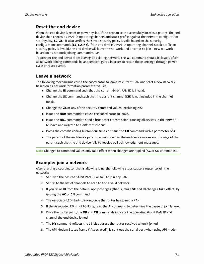
Zigbee networks End device operation
XBee/XBee-PRO® S2C Zigbee® RF Module 71
Reset the end deviceWhen the end device is reset or power cycled, if the orphan scan successfully locates a parent, the enddevice then checks its PAN ID, operating channel and stack profile against the network configurationsettings (ID, SC, ZS). It also verifies the saved security policy is valid based on the securityconfiguration commands (EE, EO, KY). If the end device's PAN ID, operating channel, stack profile, orsecurity policy is invalid, the end device will leave the network and attempt to join a new networkbased on its network joining command values.To prevent the end device from leaving an existing network, the WR command should be issued afterall network joining commands have been configured in order to retain these settings through powercycle or reset events.
Leave a networkThe following mechanisms cause the coordinator to leave its current PAN and start a new networkbased on its network formation parameter values.
n Change the ID command such that the current 64-bit PAN ID is invalid.
n Change the SC command such that the current channel (CH) is not included in the channelmask.
n Change the ZS or any of the security command values (excluding NK).
n Issue the NR0 command to cause the coordinator to leave.
n Issue the NR1 command to send a broadcast transmission, causing all devices in the networkto leave andmigrate to a different channel.
n Press the commissioning button four times or issue the CB command with a parameter of 4.
n The parent of the end device parent powers down or the end device moves out of range of theparent such that the end device fails to receive poll acknowledgment messages.
Note Changes to command values only take effect when changes are applied (AC or CN commands).
Example: join a networkAfter starting a coordinator that is allowing joins, the following steps cause a router to join thenetwork:
1. Set ID to the desired 64-bit PAN ID, or to 0 to join any PAN.
2. Set SC to the list of channels to scan to find a valid network.
3. If you SC or ID from the default, apply changes (that is, make SC and ID changes take effect) byissuing the AC or CN command.
4. The Associate LED starts blinking once the router has joined a PAN.
5. If the Associate LED is not blinking, read the AI command to determine the cause of join failure.
6. Once the router joins, the OP and CH commands indicate the operating 64-bit PAN ID andchannel the end device joined.
7. The MY command reflects the 16-bit address the router received when it joined.
8. The API Modem Status frame (“Associated”) is sent out the serial port when using API mode.

Zigbee networks Zigbee channel scanning
XBee/XBee-PRO® S2C Zigbee® RF Module 72
9. The joined end device attempts to enter low power sleepmodes based on its sleepconfiguration commands (SM, SP, SN, ST, SO).
Zigbee channel scanningRouters and end devices must scan one or more channels to discover a valid network to join. When ajoin attempt begins, the device sends a beacon request transmission on the lowest channel specifiedin the SC (Scan Channels) bitmask. If the device finds a valid PAN on the channel, it attempts to jointhe PAN on that channel. Otherwise, if the device does not find a valid PAN on the channel, it attemptsscanning on the next higher channel in the SC bitmask.The device continues to scan each channel (from lowest to highest) in the SC bitmask until it finds avalid PAN or all channels have been scanned. Once the device scans all channels, the next join attemptstarts scanning on the lowest channel specified in the SC bitmask.For example, if the SC command is set to 0x400F, the device starts scanning on channel 11 (0x0B) andscans until it finds a valid beacon, or until it scans channels 11, 12, 13, 14, and 25 have been scanned(in that order).Once an XBee router or end device joins a network on a given channel, if the XBee device receives anetwork leave command (see Leave a network), it leaves the channel it joined on and continuesscanning on the next higher channel in the SC bitmask.For example, if the SC command is set to 0x400F and the device joins a PAN on channel 12 (0x0C), ifthe XBee/XBee-PRO Zigbee RF Module leaves the channel, it starts scanning on channel 13, followedby channels 14 and 25 if it does not find a valid network. Once all channels have been scanned, thenext join attempt starts scanning on the lowest channel specified in the SC bitmask.
Manage multiple Zigbee networksIn some applications, multiple Zigbee networks may exist in proximity of each other. The applicationmay need provisions to ensure the device joins the desired network. There are a number of features inZigbee to manage joining among multiple networks. These include the following:
n PAN ID filtering
n Preconfigured security keys
n Permit joining
n Application messaging
Filter PAN IDSet ID (Extended PAN ID) to a non-zero value to configure the XBee/XBee-PRO Zigbee RF Module witha fixed PAN ID.If you set the PAN ID to a non-zero value, the device will only join a network with the same PAN ID.
Configure security keysSimilar to PAN ID filtering, this method requires that you install a known security key on a router toensure it joins a Zigbee network with the same security key.
1. Use EE (Encryption Enable) to enable security.
2. Use KY (Link Key) to set the preconfigured link key to a non-zero value.
Now the XBee router or end device will only join a network with the same security key.

Zigbee networks Zigbee channel scanning
XBee/XBee-PRO® S2C Zigbee® RF Module 73
Prevent unwanted devices from joiningYou can disable the permit-joining parameter in a network to prevent unwanted devices from joining.When you need to add a new device to a network, enable permit-joining for a short time on thedesired network.In the XBee firmware:
1. Set NJ (Node Join Time) to a value less than 0xFF on all routers and coordinator devices torestrict joining (recommended).
2. Use the Commissioning pushbutton or CB command to allow joining for a short time; for moreinformation, see Network commissioning and diagnostics .
Application messaging frameworkIf none of the previous mechanisms are feasible, you can build a messaging framework between thecoordinator and devices that join its network into the application. For example, the application code injoining devices could send a transmission to the coordinator after joining a network, and wait toreceive a defined reply message. If the application does not receive the expected response messageafter joining, it could force the device to leave and continue scanning; see NR (Network Reset).
Transmission, addressing, and routing
Addressing 75Data transmission 75Binding transmissions 78Multicast transmissions 79Fragmentation 79Data transmission examples 79RF packet routing 81Encrypted transmissions 91Maximum RF payload size 91Throughput 93ZDO transmissions 94Transmission timeouts 96
XBee/XBee-PRO® S2C Zigbee® RF Module 74
Transmission, addressing, and routing Addressing
XBee/XBee-PRO® S2C Zigbee® RF Module 75
AddressingAll Zigbee devices have two different addresses, a 64-bit and a 16-bit address. This section describesthe characteristics of each.
64-bit device addressesThe 64-bit address is a device address which is unique to each physical device. It is sometimes alsocalled the MAC address or extended address and is assigned during the manufacturing process. Thefirst three bytes of the 64-bit address is a Organizationally Unique Identifier (OUI) assigned to themanufacturer by the IEEE. The OUI of XBee devices is 0x0013A2.
16-bit device addressesA device receives a 16-bit address when it joins a Zigbee network. For this reason, the 16-bit addressis also called the network address. The 16-bit address of 0x0000 is reserved for the coordinator. Allother devices receive a randomly generated address from the router or coordinator device that allowsthe join. The 16-bit address can change under certain conditions:
n An address conflict is detected where two devices are found to have the same 16-bit address
n A device leaves the network and later joins (it can receive a different address)
All Zigbee transmissions are sent using the source and destination 16-bit addresses. The routingtables on Zigbee devices also use 16-bit addresses to determine how to route data packets throughthe network. However, since the 16-bit address is not static, it is not a reliable way to identify adevice.To solve this problem, the 64-bit destination address is often included in data transmissions toguarantee data is delivered to the correct destination. The Zigbee stack can discover the 16-bitaddress, if unknown, before transmitting data to a remote.
Application layer addressingZigbee devices support multiple application profiles, cluster IDs, and endpoints (for more information,see Zigbee application layers: in depth). Application layer addressing allows data transmissions to beaddressed to specific profile IDs, cluster IDs, and endpoints. Application layer addressing is useful if anapplication must do any of the following:
n Interoperate with other Zigbee devices outside of the Digi application profile.
n Use service and network management capabilities of the ZDO.
n Operate on a public application profile such as Home Automation or Smart Energy.
API mode provides a simple yet powerful interface that easily sends data to any profile ID, endpoint,and cluster ID combination on any device in a Zigbee network.
Data transmissionYou can send Zigbee data packets as either unicast or broadcast transmissions. Unicast transmissionsroute data from one source device to one destination device, whereas broadcast transmissions aresent to many or all devices in the network.
Broadcast transmissionsBroadcast transmissions within the Zigbee protocol are intended to be propagated throughout theentire network such that all nodes receive the transmission. To accomplish this, the coordinator and

Transmission, addressing, and routing Data transmission
XBee/XBee-PRO® S2C Zigbee® RF Module 76
all routers that receive a broadcast transmission retransmits the packet three times.
Note When a router or coordinator delivers a broadcast transmission to an end device child, thetransmission is only sent once (immediately after the end device wakes and polls the parent for anynew data). For more information, see Parent operation.
Each node that transmits the broadcast also creates an entry in a local broadcast transmission table.This entry to keeps track of each received broadcast packet to ensure the packets are nottransmitted endlessly. Each entry persists for 8 seconds, and the broadcast transmission table holds 8entries, effectively limiting network broadcast transmissions to once per second.For each broadcast transmission, the Zigbee stack reserves buffer space for a copy of the data packetthat retransmits the packet as needed. Large broadcast packets require more buffer space. Userscannot change any buffer spacing; information on buffer space is for general knowledge only. TheXBee/XBee-PRO Zigbee RF Module handles buffer spacing automatically.Since each device in the network retransmits broadcast transmissions, use broadcast messagessparingly to avoid network congestion.
Unicast transmissionsUnicast transmissions are sent from one source device to another destination device. The destinationdevice could be an immediate neighbor of the source, or it could be several hops away. Unicasttransmissions sent along a multiple hop path require some means of establishing a route to thedestination device. For more information, see RF packet routing.
Address resolutionEach device in a Zigbee network has both a 16-bit (network) address and a 64-bit (extended) address.The 64-bit address is unique and assigned to the device during manufacturing, and the 16-bit address

Transmission, addressing, and routing Data transmission
XBee/XBee-PRO® S2C Zigbee® RF Module 77
is obtained after joining a network. The 16-bit address can also change under certain conditions.When sending a unicast transmission, the Zigbee network layer uses the 16-bit address of thedestination and each hop to route the data packet. If you do not know the 16-bit address of thedestination, the Zigbee stack includes a discovery provision to automatically discover the destination16-bit address of the device before routing the data.To discover a 16-bit address of a remote, the device initiating the discovery sends a broadcast addressdiscovery transmission. The address discovery broadcast includes the 64-bit address of the remotedevice with the 16-bit address being requested. All nodes that receive this transmission check the 64-bit address in the payload and compare it to their own 64-bit address. If the addresses match, thedevice sends a response packet back to the initiator. This response includes the remote's 16-bitaddress. When the device receives the discovery response, the initiator transmits the data.You can address frames using either the extended or the network address. If you use the extendedaddress form, set the network address field to 0xFFFE (unknown). If you use the network addressform, set the extended address field to 0xFFFFFFFFFFFFFFFF (unknown).If you use an invalid 16-bit address as a destination address, and the 64-bit address is unknown(0xFFFFFFFFFFFFFFFF), the modem status message shows a delivery status code of 0x21 (networkack failure) and a discovery status of 0x00 (no discovery overhead). If you use a non-existent 64-bitaddress as a destination address, and the 16-bit address is unknown (0xFFFE), the device attemptsaddress discovery and the modem status message shows a delivery status code of 0x24 (address notfound) and a discovery status code of 0x01 (address discovery was attempted).
Address tableEach Zigbee device maintains an address table that maps a 64-bit address to a 16-bit address. When atransmission is addressed to a 64-bit address, the Zigbee stack searches the address table for anentry with a matching 64-bit address to determining the destination's 16-bit address. If the Zigbeestack does not find a known 16-bit address, it performs address discovery to discover the device'scurrent 16-bit address.
64-bit address 16-bit address
0013 A200 4000 0001 0x4414
0013 A200 400A 3568 0x1234
0013 A200 4004 1122 0xC200
0013 A200 4002 1123 0xFFFE (unknown)
For the Smart Energy profiles and related firmware, the XBee devices can store up to 10 address tableentries. For the standard firmware versions, the module supports up to 20 address table entries. Forapplications where a single device (for example, coordinator) sends unicast transmissions to morethan 10 devices, the application implements an address table to store the 16-bit and 64-bit addressesfor each remote device. Use API mode for any XBee device that sends data to more than 10 remotes.The application can then send both the 16-bit and 64-bit addresses to the XBee device in the APItransmit frames which significantly reduces the number of 16-bit address discoveries and greatlyimproves data throughput.If an application supports an address table, the size should be larger than the maximum number ofdestination addresses the device communicates with. Each entry in the address table should contain a64-bit destination address and its last known 16-bit address.When sending a transmission to a destination 64-bit address, the application searches the addresstable for a matching 64-bit address. If it finds a match, the application populates the 16-bit address

Transmission, addressing, and routing Binding transmissions
XBee/XBee-PRO® S2C Zigbee® RF Module 78
into the 16-bit address field of the API frame. If it does not find a match, set the 16-bit address to0xFFFE (unknown) in the API transmit frame. The API provides indication of a remote device's 16-bitaddress in the following frames:
n All receive data frames
n Rx Data (0x90)
n Rx Explicit Data (0x91)
n I/O Sample Data (0x92)
n Node Identification Indicator (0x95)
n Route Record Indicator (0xA1) and so forth
n Transmit status frame (0x8B)
Group tableEach router and the coordinator maintain a persistent group table. Each entry contains the following:
n Endpoint value
n Two byte group ID
n Optional name string of zero to 16 ASCII characters
n Index into the binding table
More than one endpoint may be associated with a group ID, andmore than one group ID may beassociated with a given endpoint. The capacity of the group table is 16 entries.The application always updates the 16-bit address in the address table when it receives one of theframes to ensure the table has the most recently known 16-bit address. If a transmission failureoccurs, the application sets the 16-bit address in the table to 0xFFFE (unknown).
Binding transmissionsBinding transmissions use indirect addressing to send one or more messages to other destinationdevices. The device handles an Explicit Addressing Command frame - 0x11 using the Indirect Tx Option(0x04) as a binding transmission request.
Address resolutionThe XBee/XBee-PRO Zigbee RF Module use the source endpoint and cluster ID values of a bindingtransmission as keys to lookupmatching binding table entries. For each matching binding table entry,the type field of the entry indicates whether to send a unicast or a multicast message. In the case of aunicast entry, the transmission request is updated with the Destination Endpoint and MAC Address,and unicast to its destination. In the case of a multicast entry, the device updates the message usingthe two least significant bytes of the Destination MAC Address as the groupID, andmulticast to itsdestinations.
Binding tableEach router and coordinator maintain a persistent binding table to map source endpoint and clusterID values into 64 bit destination address and endpoint values. The capacity of the binding table is 16entries.

Transmission, addressing, and routing Multicast transmissions
XBee/XBee-PRO® S2C Zigbee® RF Module 79
Multicast transmissionsXBee modules use multicast transmissions to broadcast a message to destination devices that haveactive endpoints associated with a common group ID. The device handles an Explicit AddressingCommand frame - 0x11 using the Multicast Tx Option (0x08) as a multicast transmission request.
Address resolutionThe 64 bit destination address value does not matter and we recommend that it be set to0xFFFFFFFFFFFFFFFF. Set the 16 bit destination address value to the destination groupID.
FragmentationEach unicast transmission may support up to 84 bytes of RF payload, although enabling security orusing source routing can reduce this number. For more information, see NP (Maximum PacketPayload Bytes). However, the XBee Zigbee firmware supports a Zigbee feature called fragmentationthat allows a single large data packet to be broken up into multiple RF transmissions andreassembled by the receiver before sending data out its serial port.
The transmit frame can include up to 255 bytes of data broken up into multiple transmissions andreassembled on the receiving side. If one or more of the fragmentedmessages are not received bythe receiving device, it drops the entire message, and the sender indicates a transmission failure inTransmit Status frame - 0x8B.Applications that do not wish to use fragmentation should avoid sending more than the maximumnumber of bytes in a single RF transmission (see Maximum RF payload size.If you enable RTS flow control on the receiving device (using the D6 command) it receives afragmentedmessage, it ignores RTS flow control.
Note Broadcast transmissions do not support fragmentation. Maximum payload size = up to 84 bytes.
Data transmission examplesThis section provides examples for data transmission using AT and API firmware.
Transparent modeTo send a data packet in Transparent mode (AP=0), set the DH and DL commands to match the 64- bitaddress of the destination device. DHmust match the upper 4-bytes, and DL must match the lower 4bytes. Since the coordinator always receives a 16-bit address of 0x0000, a 64-bit address of

Transmission, addressing, and routing Data transmission examples
XBee/XBee-PRO® S2C Zigbee® RF Module 80
0x0000000000000000 is the coordinator's address (in ZB firmware). The default values of DH and DLare 0x00, which sends data to the coordinator.
Example 1: Send a transmission to the coordinator.In this example, a '\r' refers to a carriage return character.A router or end device can send data in two ways. First, set the destination address (DH and DLcommands) to 0x00.
1. Enter commandmode ('+++').
2. After receiving an OK\r, issue the following commands:n ATDH0\r
n ATDL0\r
n ATCN\r
3. Verify that each of the three commands returned an OK\r response.
4. After setting these command values, all serial characters received on the UART are sent as aunicast transmission to the coordinator.
Alternatively, if the coordinator's 64-bit address is known, you can set DH and DL to the coordinator's64-bit address. Suppose the coordinator's address is 0x0013A200404A2244.
1. Enter commandmode ('+++')
2. After receiving an OK\r, issue the following commands:a. ATDH13A200\r
b. ATDL404A2244\r
c. ATCN\r
3. Verify that each of the three commands returned an OK\r response.
4. After setting these command values, all serial characters received on the UART are sent as aunicast transmission to the coordinator.
API modeUse the transmit request, or explicit transmit request frame (0x10 and 0x11 respectively) to senddata to the coordinator. The 64-bit address can either be set to 0x0000000000000000, or to the 64-bitaddress of the coordinator. The 16-bit address should be set to 0xFFFE when using the 64-bit addressof all 0x00s.To send an ASCII “1” to the coordinator's 0x00 address, use the following API frame:7E 00 0F 10 01 0000 0000 0000 0000 FFFE 00 00 31 C0If you use the explicit transmit frame, set the the cluster ID to 0x0011, the profile ID to 0xC105, andthe source and destination endpoints to 0xE8. These are the recommended defaults for datatransmissions in the Digi profile.You can send the same transmission using the following explicit transmit frame:7E 00 15 11 01 0000 0000 0000 0000 FFFE E8 E8 0011 C105 00 00 31 18The 16-bit address is set to 0xFFFE. This is required when sending to a 64-bit address of 0x00s.Suppose the coordinator's 64-bit address is 0x0013A200404A2244. The following transmit request APIframe (0x10) sends an ASCII “1” to the coordinator:7E 00 0F 10 01 0013 A200 404A 2244 0000 0000 31 18

Transmission, addressing, and routing RF packet routing
XBee/XBee-PRO® S2C Zigbee® RF Module 81
Example 2: Send a broadcast transmissionIn this example, a '\r' refers to a carriage return character.Perform the following steps to configure a broadcast transmission:
1. Enter commandmode ('+++')
2. After receiving an OK\r, issue the following commands:n ATDH0\r
n ATDLffff\r
n ATCN\r
3. Verify that each of the three commands returned an OK\r response.
4. After setting these command values, all serial characters are sent as a broadcast transmission.
API frameA transmit request API frame (0x10) can send an ASCII “1” in a broadcast transmission using thefollowing API frame:7E 00 0F 10 01 0000 0000 0000 FFFF FFFE 00 00 31 C2The destination 16-bit address is set to 0xFFFE for broadcast transmissions.
Example 3: Send an indirect (binding) transmission.This example uses the explicit transmit request frame (0x11) to send a transmission using indirectaddressing through the binding table. It assumes the binding table has already been set up to map asource endpoint of 0xE7 and cluster ID of 0x0011 to a destination endpoint and 64 bit destinationaddress. The message data is a manufacturing specific profile message using profile ID 0xC105,command ID 0x00, a ZCL Header of 151E10, transaction number EE, and a ZCL payload of000102030405:7E 001E 11 e4 FFFFFFFFFFFFFFFF FFFE E7 FF 0011 C105 00 04 151E10EE000102030405 14
Note The 64 bit destination address has been set to all 0xFF values, and the destination endpoint setto 0xFF. The Tx Option 0x04 indicates indirect addressing. The 64 bit destination address anddestination endpoint are completed by looking up data associated with binding table entries. Thismatches the following example.
Example 4: Send a multicast (group ID) broadcast.This example uses the explicit transmit request frame (0x11) to send a transmission usingmulticasting. It assumes the destination devices already have their group tables set up to associatean active endpoint with the group ID (0x1234) of the multicast transmission. The message data is amanufacturing specific profile message using profile ID 0xC105command ID 0x00, a ZCL Header of151E10, transaction number EE, and a ZCL payload of 000102030405:7E 001E 11 01 FFFFFFFFFFFFFFFF 1234 E6 FE 0001 C105 00 08 151E10EE000102030405 BC
Note The 64 bit destination address has been set to all 0xFF values, and the destination endpoint setto 0xFE. The Tx Option 0x08 indicates use of multicast (group) addressing.
RF packet routingUnicast transmissions may require some type of routing. Zigbee includes several different methods toroute data, each with its own advantages and disadvantages as summarized in the following table.
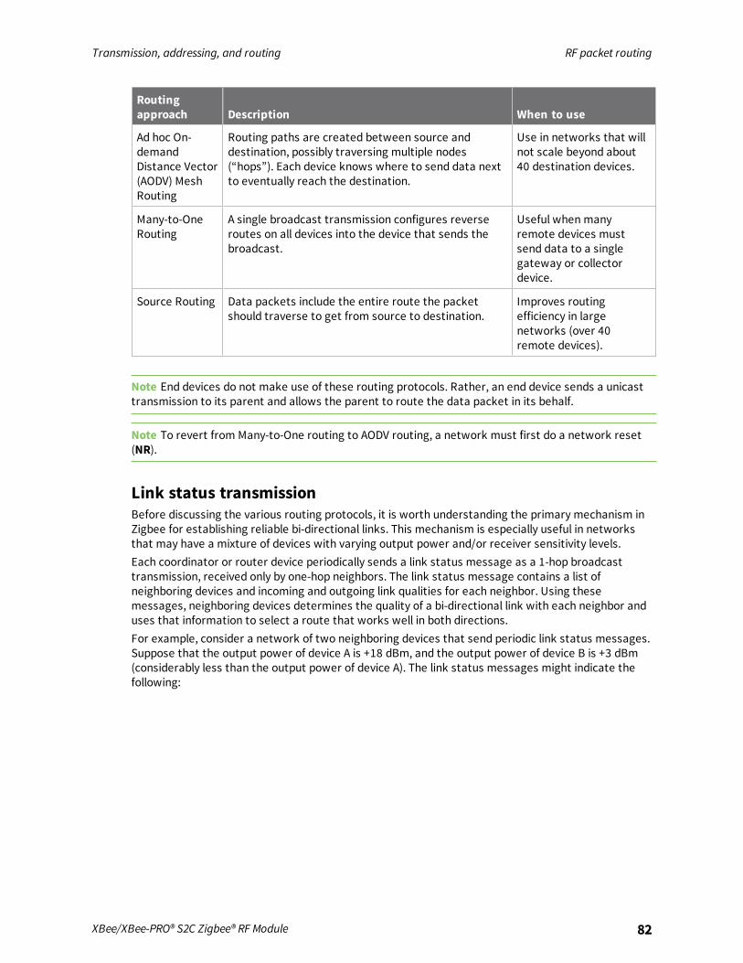
Transmission, addressing, and routing RF packet routing
XBee/XBee-PRO® S2C Zigbee® RF Module 82
Routingapproach Description When to use
Ad hoc On-demandDistance Vector(AODV) MeshRouting
Routing paths are created between source anddestination, possibly traversing multiple nodes(“hops”). Each device knows where to send data nextto eventually reach the destination.
Use in networks that willnot scale beyond about40 destination devices.
Many-to-OneRouting
A single broadcast transmission configures reverseroutes on all devices into the device that sends thebroadcast.
Useful whenmanyremote devices mustsend data to a singlegateway or collectordevice.
Source Routing Data packets include the entire route the packetshould traverse to get from source to destination.
Improves routingefficiency in largenetworks (over 40remote devices).
Note End devices do not make use of these routing protocols. Rather, an end device sends a unicasttransmission to its parent and allows the parent to route the data packet in its behalf.
Note To revert from Many-to-One routing to AODV routing, a network must first do a network reset(NR).
Link status transmissionBefore discussing the various routing protocols, it is worth understanding the primary mechanism inZigbee for establishing reliable bi-directional links. This mechanism is especially useful in networksthat may have a mixture of devices with varying output power and/or receiver sensitivity levels.Each coordinator or router device periodically sends a link status message as a 1-hop broadcasttransmission, received only by one-hop neighbors. The link status message contains a list ofneighboring devices and incoming and outgoing link qualities for each neighbor. Using thesemessages, neighboring devices determines the quality of a bi-directional link with each neighbor anduses that information to select a route that works well in both directions.For example, consider a network of two neighboring devices that send periodic link status messages.Suppose that the output power of device A is +18 dBm, and the output power of device B is +3 dBm(considerably less than the output power of device A). The link status messages might indicate thefollowing:
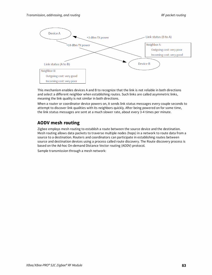
Transmission, addressing, and routing RF packet routing
XBee/XBee-PRO® S2C Zigbee® RF Module 83
This mechanism enables devices A and B to recognize that the link is not reliable in both directionsand select a different neighbor when establishing routes. Such links are called asymmetric links,meaning the link quality is not similar in both directions.When a router or coordinator device powers on, it sends link status messages every couple seconds toattempt to discover link qualities with its neighbors quickly. After being powered on for some time,the link status messages are sent at a much slower rate, about every 3-4 times per minute.
AODV mesh routingZigbee employs mesh routing to establish a route between the source device and the destination.Mesh routing allows data packets to traverse multiple nodes (hops) in a network to route data from asource to a destination. Routers and coordinators can participate in establishing routes betweensource and destination devices using a process called route discovery. The Route discovery process isbased on the Ad-hoc On-demand Distance Vector routing (AODV) protocol.Sample transmission through a mesh network:
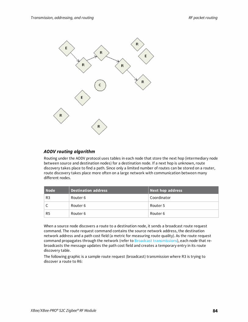
Transmission, addressing, and routing RF packet routing
XBee/XBee-PRO® S2C Zigbee® RF Module 84
AODV routing algorithmRouting under the AODV protocol uses tables in each node that store the next hop (intermediary nodebetween source and destination nodes) for a destination node. If a next hop is unknown, routediscovery takes place to find a path. Since only a limited number of routes can be stored on a router,route discovery takes place more often on a large network with communication between manydifferent nodes.
Node Destination address Next hop address
R3 Router 6 Coordinator
C Router 6 Router 5
R5 Router 6 Router 6
When a source node discovers a route to a destination node, it sends a broadcast route requestcommand. The route request command contains the source network address, the destinationnetwork address and a path cost field (a metric for measuring route quality). As the route requestcommand propagates through the network (refer to Broadcast transmissions), each node that re-broadcasts the message updates the path cost field and creates a temporary entry in its routediscovery table.The following graphic is a sample route request (broadcast) transmission where R3 is trying todiscover a route to R6:

Transmission, addressing, and routing RF packet routing
XBee/XBee-PRO® S2C Zigbee® RF Module 85
When the destination node receives a route request, it compares the ‘path cost’ field againstpreviously received route request commands. If the path cost stored in the route request is betterthan any previously received, the destination node transmits a route reply packet to the node thatoriginated the route request. Intermediate nodes receive and forward the route reply packet to thesource node (the node that originated route request).The following graphic is a sample route reply (unicast) where R6 sends a route reply to R3:
Note R6 could sendmultiple replies if it identifies a better route.
Retries and acknowledgmentsZigbee includes acknowledgment packets at both the Mac and Application Support (APS) layers. Whendata is transmitted to a remote device, it may traverse multiple hops to reach the destination. As thedevice transmits data from one node to its neighbor, it transmits an acknowledgment packet (Ack) inthe opposite direction to indicate that the transmission was successfully received. If the Ack is notreceived, the transmitting device retransmits the data, up to 4 times.This Ack is called the Mac layer acknowledgment. In addition, the device that originated thetransmission expects to receive an acknowledgment packet (Ack) from the destination device. ThisAck traverses the same path the data traversed, but in the opposite direction. If the originator fails to

Transmission, addressing, and routing RF packet routing
XBee/XBee-PRO® S2C Zigbee® RF Module 86
receive this Ack, it retransmits the data, up to 2 times until it receives an Ack. This Ack is called theZigbee APS layer acknowledgment.
Note Refer to the Zigbee specification for more details.
Many-to-One routingIn networks where many devices must send data to a central collector or gateway device, AODV meshrouting requires significant overhead. If every device in the network had to discover a route before itcould send data to the data collector, the network could easily become inundated with broadcastroute discovery messages.Many-to-one routing is an optimization for these kinds of networks. Rather than require each deviceto do its own route discovery, the device sends a single many-to-one broadcast transmission from thedata collector to establish reverse routes on all devices.The many-to-one broadcast is a route request message with the target discovery address set to theaddress of the data collector. Devices that receive this route request create a reverse many-to-onerouting table entry to create a path back to the data collector. The Zigbee stack on a device useshistorical link quality information about each neighbor to select a reliable neighbor for the reverseroute.When a device sends data to a data collector, and it finds a many-to-one route in its routing table, ittransmits the data without performing a route discovery. Send the many-to-one route requestperiodically to update and refresh the reverse routes in the network.Applications that require multiple data collectors can also use many-to-one routing. If more than onedata collector device sends a many-to-one broadcast, devices create one reverse routing table entryfor each collector.The ZB firmware uses AR (Aggregate Routing Notification) to enable many-to-one broadcasting on adevice. AR sets a time interval (measured in 10 second units) for sending the many to one broadcasttransmission.
High/Low RAM Concentrator modeWhen Many to One (MTO) requests are broadcast, DO = 40 (bit 6) determines if the concentrator isoperating in high or low RAM mode. High RAM mode indicates the concentrator has enough memoryto store source routes for the whole network, and remote nodes may stop sending route recordsafter the concentrator has successfully received one. Low RAM mode indicates the concentrator lacksRAM to store route records, and that route records be sent to the concentrator to precede everyinbound APS unicast message. By default the device uses low RAM mode.
Source routingIn applications where a device must transmit data to many remotes, AODV routing requiresperforming one route discovery for each destination device to establish a route. If there are moredestination devices than there are routing table entries, new routes overwrite established AODVroutes, causing route discoveries to occur more regularly. This can result in larger packet delays andpoor network performance.Zigbee source routing helps solve these problems. In contrast to many-to-one routing that establishesrouting paths from many devices to one data collector, source routing allows the collector to storeand specify routes for many remotes.To use source routing, a device must use the API mode, and it must send periodic many-to-one routerequest broadcasts (AR command) to create a many-to-one route to it on all devices. When remotedevices send RF data using a many-to-one route, they first send a route record transmission. The

Transmission, addressing, and routing RF packet routing
XBee/XBee-PRO® S2C Zigbee® RF Module 87
route record transmission is unicast along the many-to-one route until it reaches the data collector.As the route record traverses the many-to-one route, it appends the 16-bit address of each device inthe route into the RF payload. When the route record reaches the data collector, it contains theaddress of the sender, and the 16-bit address of each hop in the route. The data collector can storethe routing information and retrieve it later to send a source routed packet to the remote as shown inthe following images.
The data collector sends a many-to-one route request broadcast to create reverse routes on alldevices.
A remote device sends an RF data packet to the data collector. This is prefaced by a route recordtransmission to the data collector.

Transmission, addressing, and routing RF packet routing
XBee/XBee-PRO® S2C Zigbee® RF Module 88
After obtaining a source route, the data collector sends a source routed transmission to the remotedevice.
Acquiring source routesAcquiring source routes requires the remote devices to send a unicast to a data collector (device thatsends many-to-one route request broadcasts). There are several ways to force remotes to send routerecord transmissions.
1. If the application on remote devices periodically sends data to the data collector, eachtransmission forces a route record to occur.
2. The data collector can issue a network discovery command (ND command) to force all XBeedevices to send a network discovery response. A route record prefaces each network discoveryresponse.
3. You can enable periodic I/O sampling on remotes to force them to send data at a regular rate.A route record prefaces each I/O sample. For more information, see Analog and digital I/Olines.
4. If the NI string of the remote device is known, the DN command can be issued with the NIstring of the remote in the payload. The remote device with a matching NI string would send aroute record and a DN response.
Store source routesWhen a data collector receives a route record, it sends it out the serial port as a Route RecordIndicator - 0xA1. To use source routing, the application receives these frames and stores the sourceroute information.
Send a source routed transmissionTo send a source routed transmission, the application must send a Create Source Route - 0x21 to theXBee/XBee-PRO Zigbee RF Module to create a source route in its internal source route table. Aftersending the Create Source Route frame, the application can send data transmission or remotecommand request frames as needed to the same destination, or any destination in the source route.Once data must be sent to a new destination (a destination not included in the last source route), theapplication must first send a new Create Source Route - 0x21.

Transmission, addressing, and routing RF packet routing
XBee/XBee-PRO® S2C Zigbee® RF Module 89
Note If a Create Source Route API frame does not precede the data frames, you may encounter dataloss.
The XBee/XBee-PRO Zigbee RF Module can buffer one source route that includes up to 11 hops(excluding source and destination). For example, suppose a network exists with a coordinator and 5routers (R1, R2, R3, R4, R5) with known source routes as shown in the following image.
To send a source-routed packet to R3, the application sends a Create Source Route API frame (0x21)to the XBee, with a destination of R3, and 2 hops (R1 and R2). If the 64- bit address of R3 is0x0013A200 404a1234 and the 16-bit addresses of R1, R2, and R3 are:
Device 16-bit address
R1 0xAABB
R2 0xCCDD
R3 0xEEFF
The Create Source Route API frame would be:7E 0012 21 00 0013A200 404A1234 EEFF 00 02 CCDD AABB 5C
Field composition
0x0012 length
0x21 API ID (create source route)
0x00 frame ID (set to 0 always)
0x0013A200 404A1234 64-bit address of R3 (destination)
0xEEFF 16-bit address of R3 (destination)

Transmission, addressing, and routing RF packet routing
XBee/XBee-PRO® S2C Zigbee® RF Module 90
0x00 Route options (set to 0)
0x02 Number of intermediate devices in the source route
0xCCDD Address of furthest device (1-hop from target)
0xAABB Address of next-closer device
0x5C Checksum (0xFF - SUM (all bytes after length))
Repair source routesIt is possible for a network to have an existing source route fail (for example, a device in the routemoves or goes down). If a device goes down in a source routed network, all routes that used thedevice will be broken.As mentioned previously, source routing must be used with many-to-one routing. A device that usessource routing must also send a periodic many-to-one broadcast in order to keep routes fresh. If asource route breaks, remote devices send in new route record transmissions to the data collector toprovide it with a new source route. This requires that remote devices periodically send datatransmissions into the data collector. For more information, see Acquiring source routes.
Retries and acknowledgmentsZigbee includes acknowledgment packets at both the Mac and Application Support (APS) layers. Whendata transmits to a remote device, it may traverse multiple hops to reach the destination. As datatransmits from one node to its neighbor, an acknowledgment packet (Ack) transmits in the oppositedirection to indicate that the transmission was successfully received. If the transmitting device doesnot receive the Ack, it retransmits the data up to four times. This Ack is called the Mac layeracknowledgment.In addition, the device that originated the transmission expects to receive an acknowledgment packet(Ack) from the destination device. This Ack traverses the same path that the data traversed, but in theopposite direction. If the originator fails to receive this Ack, it retransmits the data, up to two timesuntil an Ack is received. This Ack is called the Zigbee APS layer acknowledgment.
Note Refer to the Zigbee specification for more details.
Disable MTO routingTo disable MTO (many-to-one) routing in a network, first reconfigure the AR setting on the aggregatorand then broadcast a network wide power reset—0x08 of RE command—to rebuild the routing tables.
1. Set AR on the aggregator to 0xFF.
2. Complete an AC command to enact the change.
3. Complete a WR command if the saved configuration setting value for AR is not 0xFF.
This ends the periodic broadcast of aggregator messages if the previous setting was 0x01 - 0xFE, andprevents a single broadcast after a power reset if the previous setting was 0x00. Broadcast a FRremote command to the network and wait for the network to reform. This removes the aggregator'sstatus as an aggregator from the network's routing tables so that no more route records will be sentto the aggregator.
Disable route recordsIf an aggregator collects route records from the nodes of the network and no longer needs routerecords sent (which consume network throughput) :

Transmission, addressing, and routing Encrypted transmissions
XBee/XBee-PRO® S2C Zigbee® RF Module 91
1. Set Bit 6 of DO to Enable High RAM Concentrator mode. High RAM mode means the aggregatorhas sufficient memory to hold route records for its potential destinations.
2. Set AR to 0x00 for a one-time broadcast (which some nodes might miss), or a value in therange of 0x01 to 0xFE (in units of 10 seconds) to periodically send a broadcast to inform thenetwork that the aggregator is operating in High RAM Concentrator mode and no longer needsto receive route records.
3. Use Create Source Route - 0x21 to load the route record for a destination into the localdevice's source route table.
4. Send a unicast to the destination. The route record embeds in the payload and determines thesequence of routers to use in transmitting the unicast to the destination. After receiving theunicast, the destination no longer sends route records to the aggregator, now that it hasconfirmed the High RAM Concentrator aggregator 'knows' its route record.
Clear the source route tableTo clear the source route table, change the AR setting from a non-0xFF setting to 0xFF and completean AC command. To re-establish periodic aggregator broadcasts, change the AR setting to a non-0xFFsetting and complete an AC command.
Encrypted transmissionsEncrypted transmissions are routed similar to non-encrypted transmissions with one exception. As anencrypted packet propagates from one device to another, each device decrypts the packet using thenetwork key and authenticates the packet by verifying packet integrity. It then re-encrypts thepacket with its own source address and frame counter values and sends the message to the next hop.This process adds some overhead latency to unicast transmissions, but it helps prevent replayattacks. For more information see Zigbee security.
Maximum RF payload sizeThe NP command returns the maximum payload size in bytes. The actual maximum payload is afunction of the following:
n message type (broadcast or unicast)
n AP setting
n APS encryption option
n Source-routing
Broadcasts, which cannot be encrypted with APS or fragmented have a maximum payload of 0x54bytes (84 bytes). Unicasts where AP is 0 also have a maximum payload of 0x54 bytes. A non-zero APmeans NP will be 0xFF or 255 bytes.For broadcast messages and unicast messages when AP==0, the maximum payload is 0x54 bytes.For unicast messages when AP is nonzero (API mode), the maximum payload is 0xFF (255 bytes)bytes. If the combination of payload and optional APS encryption overhead (EE1, TxOption 0x20) is toohigh, the message fragments into a maximum of five fragments. The firmware encrypts and transmitseach fragment separately. The destination radio reassembles the fragments into a full message.For Smart Energy firmware revision 5x32 and earlier, NP==0x80. As of 5x56, NP==0xFF.

Transmission, addressing, and routing Maximum RF payload size
XBee/XBee-PRO® S2C Zigbee® RF Module 92
The maximum payload is calculated to estimate for aggregator source-routing. To reduce themaximum payload, when an aggregator sends a source-routedmessage it embeds the route into themessage as overhead, or into each fragment of the message, if fragmentation is necessary. If you useAPS encryption (EE1, Tx Option 0x20), it reduces the number further.The route overhead is 2 bytes plus 2 bytes per hop. The bytes are:
n One byte is the number of hops
n One byte is an index into the route list that increments in value at each hop
n Other data is a list of the 16-bit network addresses of the routing radios
Firmware revisions before 4x58 support a maximum of 11 aggregator source-routed hops. Firmwarerevisions 4x58 and following support a maximum of 25 aggregator source-routed hops.Aggregator source-routed payloadmaximums do not apply to messages that are sourced by non-aggregator nodes, which send route records ahead of their messages to aggregators. Aggregatorsare either Coordinators or Routers which have the following:
n Source routing enabled or
n AR setting which is not 0xFF
The following table shows the aggregator source-routed payloadmaximums as a function of hops andAPS encryption:
Hops Maximum encrypted payload Maximum unencrypted payload
1 255 255
2 255 255
3 255 255
4 255 255
5 255 255
6 215 255
7 205 250
8 195 240
9 185 230
10 175 220
11 165 210
12 155 200
13 145 190
14 135 180
15 125 170
16 115 160
17 105 150
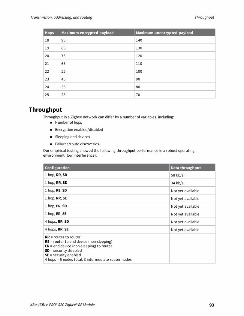
Transmission, addressing, and routing Throughput
XBee/XBee-PRO® S2C Zigbee® RF Module 93
Hops Maximum encrypted payload Maximum unencrypted payload
18 95 140
19 85 130
20 75 120
21 65 110
22 55 100
23 45 90
24 35 80
25 25 70
ThroughputThroughput in a Zigbee network can differ by a number of variables, including:
n Number of hops
n Encryption enabled/disabled
n Sleeping end devices
n Failures/route discoveries.
Our empirical testing showed the following throughput performance in a robust operatingenvironment (low interference).
Configuration Data throughput
1 hop, RR, SD 58 kb/s
1 hop, RR, SE 34 kb/s
1 hop, RE, SD Not yet available
1 hop, RR, SE Not yet available
1 hop, ER, SD Not yet available
1 hop, ER, SE Not yet available
4 hops, RR, SD Not yet available
4 hops, RR, SE Not yet available
RR = router to routerRE = router to end device (non-sleeping)ER = end device (non-sleeping) to routerSD = security disabledSE = security enabled4 hops = 5 nodes total, 3 intermediate router nodes
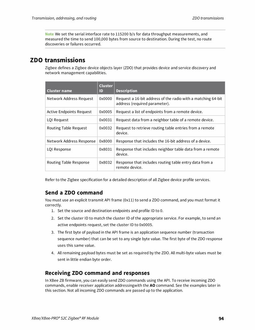
Transmission, addressing, and routing ZDO transmissions
XBee/XBee-PRO® S2C Zigbee® RF Module 94
Note We set the serial interface rate to 115200 b/s for data throughput measurements, andmeasured the time to send 100,000 bytes from source to destination. During the test, no routediscoveries or failures occurred.
ZDO transmissionsZigbee defines a Zigbee device objects layer (ZDO) that provides device and service discovery andnetwork management capabilities.
Cluster nameClusterID Description
Network Address Request 0x0000 Request a 16-bit address of the radio with a matching 64-bitaddress (required parameter).
Active Endpoints Request 0x0005 Request a list of endpoints from a remote device.
LQI Request 0x0031 Request data from a neighbor table of a remote device.
Routing Table Request 0x0032 Request to retrieve routing table entries from a remotedevice.
Network Address Response 0x8000 Response that includes the 16-bit address of a device.
LQI Response 0x8031 Response that includes neighbor table data from a remotedevice.
Routing Table Response 0x8032 Response that includes routing table entry data from aremote device.
Refer to the Zigbee specification for a detailed description of all Zigbee device profile services.
Send a ZDO commandYou must use an explicit transmit API frame (0x11) to send a ZDO command, and you must format itcorrectly.
1. Set the source and destination endpoints and profile ID to 0.
2. Set the cluster ID to match the cluster ID of the appropriate service. For example, to send anactive endpoints request, set the cluster ID to 0x0005.
3. The first byte of payload in the API frame is an application sequence number (transactionsequence number) that can be set to any single byte value. The first byte of the ZDO responseuses this same value.
4. All remaining payload bytes must be set as required by the ZDO. All multi-byte values must besent in little endian byte order.
Receiving ZDO command and responsesIn XBee ZB firmware, you can easily send ZDO commands using the API. To receive incoming ZDOcommands, enable receiver application addressingwith the AO command. See the examples later inthis section. Not all incoming ZDO commands are passed up to the application.

Transmission, addressing, and routing ZDO transmissions
XBee/XBee-PRO® S2C Zigbee® RF Module 95
When a ZDO message is received on endpoint 0 and profile ID 0, the cluster ID indicates the type ofZDO message received. The first byte of payload is generally a sequence number that corresponds toa sequence number of a request. The remaining bytes are set as defined by the ZDO. Similar to a ZDOrequest, all multi-byte values in the response are in little endian byte order.
Example 1: Send a ZDO LQI request to read the neighbor table contents of aremoteLooking at the Zigbee specification, the cluster ID for an LQI Request is 0x0031, and the payload onlyrequires a single byte (start index). This example sends an LQI request to a remote device with a 64-bit address of 0x0013A200 40401234. The start index is set to 0, and the transaction sequencenumber is set to 0x76.
API Frame7E 0016 11 01 0013A200 40401234 FFFE 00 00 0031 0000 00 00 76 00 CE
Field composition
0x0016 length
0x11 Explicit transmit request
0x01 Frame ID (set to a non-zero value to enable the transmit status message, or setto 0 to disable)
0x0013A20040401234
64-bit address of the remote
0xFFFE 16-bit address of the remote (0xFFFE = unknown). Optionally, set to the 16-bitaddress of the destination if known.
0x00 Source endpoint
0x00 Destination endpoint
0x0031 Cluster ID (LQI Request, or Neighbor table request)
0x0000 Profile ID (Zigbee device profile)
0x00 Broadcast radius
0x00 Tx Options
0x76 Transaction sequence number
0x00 Required payload for LQI request command
0xCE Checksum (0xFF - SUM (all bytes after length))
DescriptionThis API frame sends a ZDO LQI request (neighbor table request) to a remote device to obtain datafrom its neighbor table. You must set the AO command correctly on an API device to enable theexplicit API receive frames to receive the ZDO response.
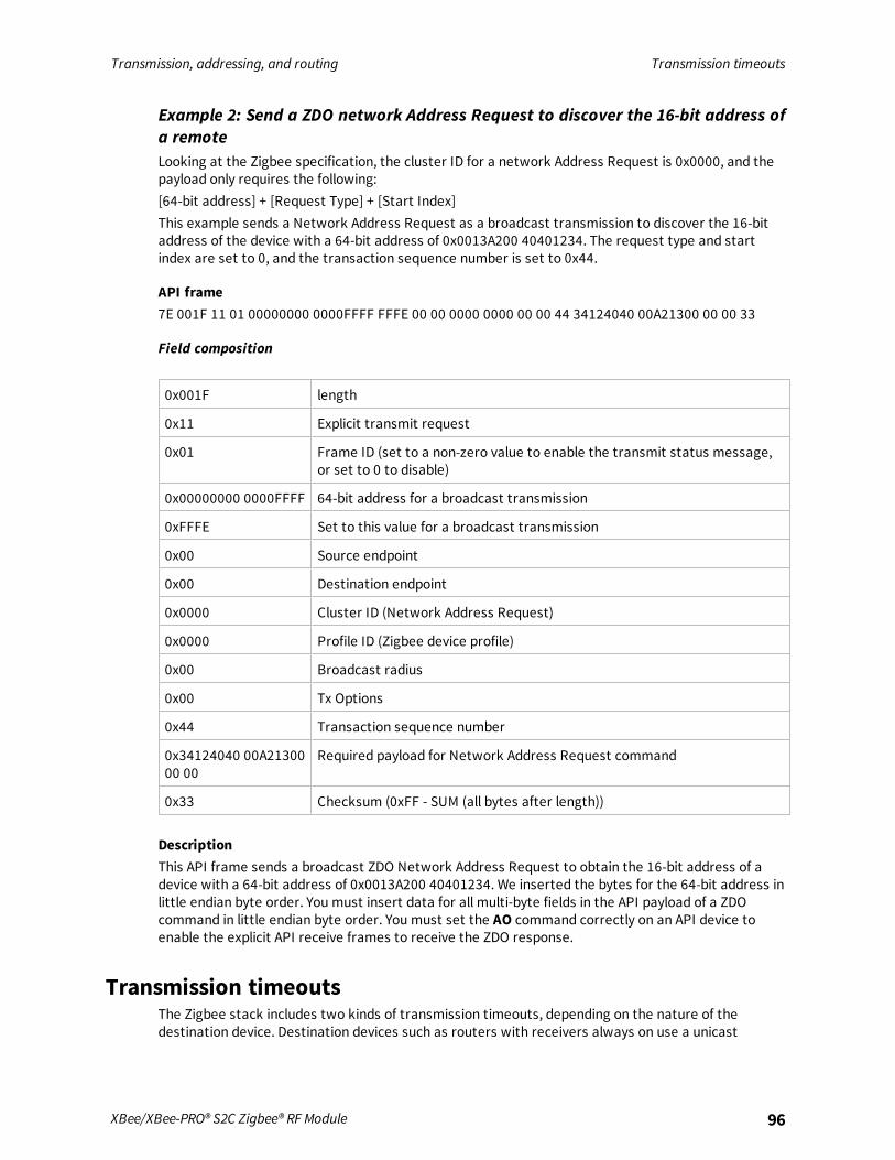
Transmission, addressing, and routing Transmission timeouts
XBee/XBee-PRO® S2C Zigbee® RF Module 96
Example 2: Send a ZDO network Address Request to discover the 16-bit address ofa remoteLooking at the Zigbee specification, the cluster ID for a network Address Request is 0x0000, and thepayload only requires the following:[64-bit address] + [Request Type] + [Start Index]This example sends a Network Address Request as a broadcast transmission to discover the 16-bitaddress of the device with a 64-bit address of 0x0013A200 40401234. The request type and startindex are set to 0, and the transaction sequence number is set to 0x44.
API frame7E 001F 11 01 00000000 0000FFFF FFFE 00 00 0000 0000 00 00 44 34124040 00A21300 00 00 33
Field composition
0x001F length
0x11 Explicit transmit request
0x01 Frame ID (set to a non-zero value to enable the transmit status message,or set to 0 to disable)
0x00000000 0000FFFF 64-bit address for a broadcast transmission
0xFFFE Set to this value for a broadcast transmission
0x00 Source endpoint
0x00 Destination endpoint
0x0000 Cluster ID (Network Address Request)
0x0000 Profile ID (Zigbee device profile)
0x00 Broadcast radius
0x00 Tx Options
0x44 Transaction sequence number
0x34124040 00A2130000 00
Required payload for Network Address Request command
0x33 Checksum (0xFF - SUM (all bytes after length))
DescriptionThis API frame sends a broadcast ZDO Network Address Request to obtain the 16-bit address of adevice with a 64-bit address of 0x0013A200 40401234. We inserted the bytes for the 64-bit address inlittle endian byte order. You must insert data for all multi-byte fields in the API payload of a ZDOcommand in little endian byte order. You must set the AO command correctly on an API device toenable the explicit API receive frames to receive the ZDO response.
Transmission timeoutsThe Zigbee stack includes two kinds of transmission timeouts, depending on the nature of thedestination device. Destination devices such as routers with receivers always on use a unicast

Transmission, addressing, and routing Transmission timeouts
XBee/XBee-PRO® S2C Zigbee® RF Module 97
timeout. The unicast timeout estimates a timeout based on the number of unicast hops the packetshould traverse to get data to the destination device. For transmissions destined for end devices, theZigbee stack uses an extended timeout that includes the unicast timeout (to route data to the enddevice's parent), and it includes a timeout for the end device to finish sleeping, wake, and poll theparent for data.The Zigbee stack includes some provisions for a device to detect if the destination is an end device.The Zigbee stack uses the unicast timeout unless it knows the destination is an end device.The XBee API includes a transmit options bit that you can set to specify the extended timeout used fora given transmission. If you set this bit, the extended timeout will be used when sending RF data tothe specified destination. To improve routing reliability, applications set the extended timeout bitwhen sending data to end devices if:
n The application sends data to 10 or more remote devices, some of which are end devices.
n The end devices may sleep longer than the unicast timeout.
Equations for these timeouts are computed in the following sections.
Note The timeouts in this section are worst-case timeouts and should be padded by a few hundredmilliseconds. These worst-case timeouts apply when an existing route breaks down (for example,intermediate hop or destination device moved).
Unicast timeoutSet the unicast timeout with the NH command. The actual unicast timeout is computed as ((50 * NH)+ 100). The default NH value is 30 which equates to a 1.6 second timeout.The unicast timeout includes 3 transmission attempts (1 attempt and 2 retries).The maximum total timeout is approximately:3 * ((50 * NH) + 100)For example, if NH=30 (0x1E), the unicast timeout is approximately 3 * ((50 * 30) + 100) or one of thefollowing:
n 3 * (1500 + 100)
n 3 * (1600)
n 4800 ms
n 4.8 seconds
Extended timeoutThe worst-case transmission timeout when you are sending data to an end device is a larger issuethan when transmitting to a router or coordinator. As described in Parent operation, RF data packetsare sent to the parent of the end device, which buffers the packet until the end device wakes toreceive it. The parent buffers an RF data packet for up to (1.2 * SP) time.To ensure the end device has adequate time to wake and receive the data, the extended transmissiontimeout to an end device is:(50 * NH) + (1.2 * SP)This timeout includes the packet buffering timeout (1.2 * SP) and time to account for routing throughthe mesh network (50 * NH).If no acknowledgment is received within this time, the sender resends the transmission up to twomore times. With retries included, the longest transmission timeout when sending data to an enddevice is:

Transmission, addressing, and routing Transmission timeouts
XBee/XBee-PRO® S2C Zigbee® RF Module 98
3 * ((50 * NH) + (1.2 * SP))The SP value in both equations must be entered in millisecond units. The SP command setting uses 10ms units andmust be converted to milliseconds to be used in this equation.For example, suppose a router is configured with NH=30 (0x1E) and SP=0x3E8 (10,000 ms), and that itis either trying to send data to one of its end device children, or to a remote end device. The totalextended timeout to the end device is approximately:3 * ((50 * NH) + (1.2 * SP)) or one of the following:
n 3 * (1500 + 12000)
n 3 * (13500)
n 40500 ms
n 40.5 seconds
Transmission examplesExample 1: Send a unicast API data transmission to the coordinator using 64-bit address 0, withpayload “TxData”.
API frame7E 0014 10 01 00000000 00000000 FFFE 00 00 54 78 44 61 74 61 AB
Field composition
0x0014 length
0x10 API ID (TX data)
0x01 Frame ID (set greater than 0 to enable the TX-status response)
0x00000000 00000000 64-bit address of coordinator (ZB definition)
0xFFFE Required 16-bit address if sending data to 64-bit address of 0
0x00 Broadcast radius (0 = max hops)
0x00 Tx options
0x54 78 44 61 74 61 ASCII representation of “TxData” string
0xAB Checksum (0xFF - SUM (all bytes after length))
DescriptionThis transmission sends the string “TxData” to the coordinator, without knowing the 64-bit address ofthe coordinator device. ZB firmware defines a 64-bit address of 0 as the coordinator. If thecoordinator's 64-bit address was known, the 64-bit address of 0 could be replaced with thecoordinator's 64-bit address, and the 16-bit address could be set to 0.
Example 2: Send a broadcast API data transmission that all devices can receive (including sleeping enddevices), with payload “TxData”.

Transmission, addressing, and routing Transmission timeouts
XBee/XBee-PRO® S2C Zigbee® RF Module 99
API frame7E 0014 10 01 00000000 0000FFFF FFFE 00 00 54 78 44 61 74 61 AD
Field composition
0x0014 length
0x10 API ID (TX data)
0x01 Frame ID (set to a non-zero value to enable the TX-status response)
0x00000000 0000FFFF Broadcast definition (including sleeping end devices)
0xFFFE Required 16-bit address to send broadcast transmission
0x00 Broadcast radius (0 = max hops)
0x00 Tx options
0x54 78 44 61 74 61 ASCII representation of “TxData” string
0xAD Checksum (0xFF - SUM (all bytes after length))
DescriptionThis transmission sends the string “TxData” as a broadcast transmission. Since the destinationaddress is set to 0xFFFF, all devices, including sleeping end devices can receive this broadcast.If receiver application addressing is enabled, the XBee/XBee-PRO Zigbee RF Module reports allreceived data frames in the explicit format (0x91) to indicate the source and destination endpoints,cluster ID, and profile ID where each packet was received. Status messages like modem status androute record indicators are not affected.To enable receiver application addressing, set the AO command to 1 using the AT Command frame -0x08 as follows:
API frame7E 0005 08 01 414F 01 65
Field composition
0x0005 length
0x08 API ID (AT command)
0x01 Frame ID (set to a non-zero value to enable AT command response frames)
0x414F ASCII representation of 'A','O' (the command being issued)
0x01 Parameter value
0x65 Checksum (0xFF - SUM (all bytes after length))
DescriptionSetting AO = 1 is required for the XBee/XBee-PRO Zigbee RF Module to use the Explicit Rx Indicatorframe - 0x91 when receiving RF data packets. This is required if the application needs indication of

Transmission, addressing, and routing Transmission timeouts
XBee/XBee-PRO® S2C Zigbee® RF Module 100
source or destination endpoint, cluster ID, or profile ID values used in received Zigbee data packets.ZDO messages can only be received if AO = 1.

Zigbee security
Security modes 102Zigbee security model 102Implement security on the XBee/XBee-PRO Zigbee RF Module 105
XBee/XBee-PRO® S2C Zigbee® RF Module 101

Zigbee security Security modes
XBee/XBee-PRO® S2C Zigbee® RF Module 102
Zigbee supports various levels of security that you can configure depending on the needs of theapplication. Security provisions include:
n 128-bit AES encryption
n Two security keys that can be preconfigured or obtained during joining
n Support for a trust center
n Provisions to ensure message integrity, confidentiality, and authentication
This section describes various security features defined in the Zigbee specification and illustrates howyou can configure theXBee/XBee-PRO Zigbee RF Modules to support these features.
Security modesThe Zigbee standard supports three security modes: residential, standard, and high security.
n Residential security requires a network key be shared among devices.
n Standard security adds a number of optional security enhancements over residential security,including an APS layer link key.
n High security adds entity authentication and a number of other features not widelysupported.
XBee ZB modules primarily support standard security, although end devices that support residentialsecurity can join and interoperate with standard security devices. This section focuses on materialthat is relevant to standard security.
Zigbee security modelZigbee security is applied to the Network and APS layers. Packets are encrypted with 128-bit AESencryption. A network key and optional link key can be used to encrypt data. Only devices with thesame keys are able to communicate together in a network. Routers and end devices that willcommunicate on a secure network must obtain the correct security keys.
Network layer securityThe network key is used to encrypt the APS layer and application data. In addition to encryptingapplication messages, network security is also applied to route request and reply messages, APScommands, and ZDO commands. Network encryption is not applied to MAC layer transmissions suchas beacon transmissions. If you enable security on a network, all data packets are encrypted with thenetwork key.

Zigbee security Zigbee security model
XBee/XBee-PRO® S2C Zigbee® RF Module 103
Frame counterThe network header of encrypted packets includes a 32-bit frame counter. Each device in the networkmaintains a 32-bit frame counter that increments for every transmission. In addition, devices trackthe last known 32-bit frame counter for each of its neighbors. If a device receives a packet from aneighbor with a smaller frame counter than previously seen, it discards the packet. The device usesthe frame counter to protect against replay attacks.If the frame counter reaches a maximum value of 0xFFFFFFFF, it does not wrap to 0 and cannot sendany more transmissions. Due to the size of the frame counters, reaching the maximum value isuncommon for most applications. The following table shows the required time for the frame counterto reach its maximum value.
Average Transmission Rate Time until 32-bit frame counter expires
1 / second 136 years
10 / second 13.6 years
To clear the frame counters without compromising security, you can change the network key in thenetwork. When the network key is updated, the frame counters on all devices reset to 0. See Networkkey updates for details.
Message integrity codeThe network header, APS header, and application data are all authenticated with 128-bit AES. Thedevice performs a hash on these fields and is appended as a 4-byte message integrity code (MIC) tothe end of the packet. The MIC allows receiving devices to ensure the message has not been changed.The MIC provides message integrity in the Zigbee security model. If a device receives a packet and theMIC does not match the device’s own hash of the data, it drops the packet.
Network layer encryption and decryptionPackets with network layer encryption are encrypted and decrypted by each hop in a route. When adevice receives a packet with network encryption, it decrypts the packet and authenticates thepacket. If the device is not the destination, it then encrypts and authenticates the packet, using itsown frame counter and source address in the network header section.Since the device performs network encryption at each hop, packet latency is slightly longer in anencrypted network than in a non-encrypted network. Also, security requires 18 bytes of overhead toinclude a 32-bit frame counter, an 8-byte source address, 4-byte MIC, and 2 other bytes. This reducesthe number of payload bytes that can be sent in a data packet.
Network key updatesZigbee supports a mechanism for changing the network key in a network. When the network key ischanged, the frame counters in all devices reset to 0.
APS layer securityAPS layer security can be used to encrypt application data using a key that is shared between sourceand destination devices. Where network layer security is applied to all data transmissions and isdecrypted and reencrypted on a hop-by-hop basis, APS security is optional and provides end-to-endsecurity using an APS link key known by only the source and destination device. APS security cannotbe applied to broadcast transmissions.
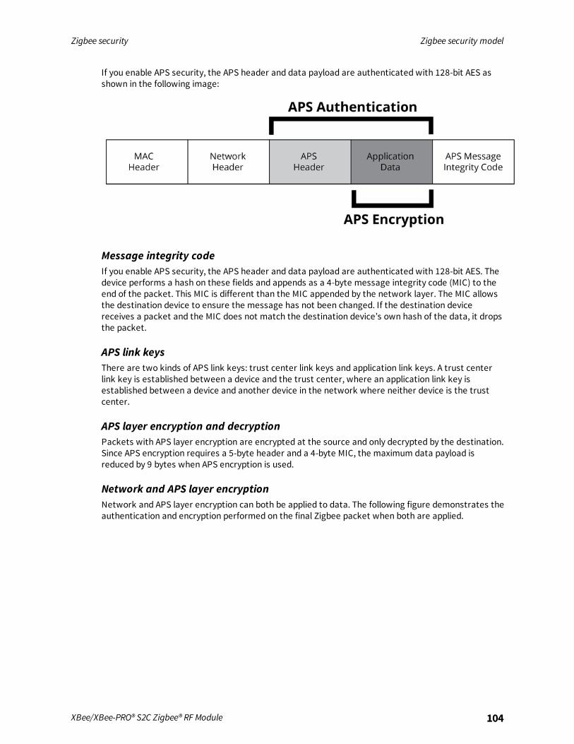
Zigbee security Zigbee security model
XBee/XBee-PRO® S2C Zigbee® RF Module 104
If you enable APS security, the APS header and data payload are authenticated with 128-bit AES asshown in the following image:
Message integrity codeIf you enable APS security, the APS header and data payload are authenticated with 128-bit AES. Thedevice performs a hash on these fields and appends as a 4-byte message integrity code (MIC) to theend of the packet. This MIC is different than the MIC appended by the network layer. The MIC allowsthe destination device to ensure the message has not been changed. If the destination devicereceives a packet and the MIC does not match the destination device’s own hash of the data, it dropsthe packet.
APS link keysThere are two kinds of APS link keys: trust center link keys and application link keys. A trust centerlink key is established between a device and the trust center, where an application link key isestablished between a device and another device in the network where neither device is the trustcenter.
APS layer encryption and decryptionPackets with APS layer encryption are encrypted at the source and only decrypted by the destination.Since APS encryption requires a 5-byte header and a 4-byte MIC, the maximum data payload isreduced by 9 bytes when APS encryption is used.
Network and APS layer encryptionNetwork and APS layer encryption can both be applied to data. The following figure demonstrates theauthentication and encryption performed on the final Zigbee packet when both are applied.

Zigbee security Implement security on the XBee/XBee-PRO Zigbee RF Module
XBee/XBee-PRO® S2C Zigbee® RF Module 105
Trust centerZigbee defines a trust center device that is responsible for authenticating devices that join thenetwork. The trust center also manages link key distribution in the network.
Forming or joining a secure networkThe coordinator is responsible for selecting a network encryption key. This key can either bepreconfigured or randomly selected. In addition, the coordinator generally operates as a trust centerandmust select the trust center link key. The trust center link key can also be preconfigured orrandomly selected.Devices that join the network must obtain the network key when they join. When a device joins asecure network, the network and link keys can be sent to the joining device. If the joining device has apreconfigured trust center link key, the network key will be sent to the joining device encrypted by thelink key. Otherwise, if the joining device is not preconfigured with the link key, the device could onlyjoin the network if the network key is sent unencrypted ("in the clear").The trust center must decide whether or not to send the network key unencrypted to joining devicesthat are not preconfigured with the link key. We do not recommend sending the network keyunencrypted as it can open a security hole in the network. To maximize security, preconfigure deviceswith the correct link key.
Implement security on the XBee/XBee-PRO Zigbee RF ModuleIf you enable security in the XBee Zigbee firmware, devices acquire the network key when they join anetwork. Data transmissions are always encrypted with the network key, and can optionally be end-to-end encrypted with the APS link key.
Zigbee security Implement security on the XBee/XBee-PRO Zigbee RF Module
XBee/XBee-PRO® S2C Zigbee® RF Module 106
Enabling securityTo enable security on a device, the Encryption Enable (EE) parameter must be set to 1. When theparameter value changes, the XBee module leaves the network (PAN ID and channel) it was operatingon and attempt to form or join a new network.If you set EE to 1, all data transmissions are encrypted with the network key. When you enablesecurity, the maximum number of bytes in a single RF transmission will be reduced. For moreinformation, see NP (Maximum Packet Payload Bytes).
Note The EE parameter must be set the same on all devices in a network. Changes to the EEcommand should be written to non-volatile memory (to be preserved through power cycle or resetevents) using the WR command.
Setting the network security keyThe coordinator selects the network security key for the network using the Network Encryption Key(NK) parameter (write-only). If NK = 0 (default), the coordinator will selects a random network key.Otherwise, you set NK to a non-zero value, it uses this value as network security key.NK is only supported on the coordinator. Routers and end devices with security enabled (EE = 1)acquire the network key when they join a network. They receive the network key encrypted with thelink key if they share a preconfigured link key with the coordinator.
Note In Zigbee, if EE and EO are set to 0x01, then the device sends the network key in the clear(unencrypted) with the link key at association time. This may be a useful setting in developmentenvironments, but we discourage it for product deployment for security reasons.
Set the APS trust center link keyThe coordinator must also select the trust center link key, using KY (Link Key). If KY = 0 (default), thecoordinator selects a random trust center link key (not recommended). Otherwise, if KY is set greaterthan 0, the device uses this value as the pre-configured trust center link key. KY is write-only andcannot be read.
Note Application link keys sent between two devices where neither device is the coordinator are notsupported in Zigbee firmware.
Random trust center link keysIf the coordinator selects a random trust center link key (KY = 0, default), then it allows devices to jointhe network without having a pre-configured link key. However, this sends the network keyunencrypted over-the-air to joining devices and is not recommended.
Pre-configured trust center link keysIf the coordinator uses a pre-configured link key (KY > 0), then it will not send the network keyunencrypted to joining devices. Only devices with the correct pre-configured link key can to join andcommunicate on the network.
Enable APS encryptionAPS encryption is an optional layer of security that uses the link key to encrypt the data payload.Unlike network encryption that is decrypted and encrypted on a hop-by-hop basis, APS encryption is

Zigbee security Implement security on the XBee/XBee-PRO Zigbee RF Module
XBee/XBee-PRO® S2C Zigbee® RF Module 107
only decrypted by the destination device. The XBee/XBee-PRO Zigbee RF Module must be configuredwith security enabled (EE set to 1) to use APS encryption.APS encryption can be enabled in API firmware on a per-packet basis. To enable APS encryption for agiven transmission, set the "enable APS encryption" transmit options bit in the API transmit frame.Enabling APS encryption decreases the maximum payload size by nine bytes.
Use a trust centerUse the Encryption Options (EO) parameter define the coordinator as a trust center. If the coordinatoris a trust center, it received alerts to all new join attempts in the network. The trust center also hasthe ability to update or change the network key on the network.In ZB firmware, you can establish a secure network with or without a trust center. Network and APSlayer encryption are supported regardless of whether you use a trust center.
Updating the network key with a trust center.If the trust center has started a network and the NK value changes, the coordinator updates thenetwork key on all devices in the network. Changes to NKwill not force the device to leave thenetwork. The network continues to operate on the same channel and PAN ID, but the devices in thenetwork update their network key, increment their network key sequence number, and restore theirframe counters to 0.
Updating the network key without a trust center.If the coordinator is not running as a trust center, the Network Reset (NR1) command can be used toforce all devices in the network to leave the current network and rejoin the network on anotherchannel. When devices leave and reform then network, the frame counters are reset to 0. Thisapproach causes the coordinator to form a new network that the remaining devices should join.Resetting the network in this manner brings the coordinator and routers in the network down forabout ten seconds, and causes the 16-bit PAN ID and 16-bit addresses of the devices to change.In Zigbee firmware, a secure network can be established with or without a trust center. Network andAPS layer encryption are supported regardless of whether a trust center is used.
Security examplesThis section covers some sample XBee device configurations to support different security modes andlists several AT commands with suggested parameter values.In AT commandmode, issue each command with a leading 'AT' and no '=' sign: For example, EE1. Inthe API, the two byte command is used in the command field, and parameters are populated as binaryvalues in the parameter field.
Example 1: Forming a network with security (pre-configured link keys)1. Start a coordinator with the following settings:
a. ID = 2234 (arbitrarily selected)
b. EE = 1
c. NK = 0
d. KY = 4455
e. WR (save networking parameters to preserve them through power cycle)

Zigbee security Implement security on the XBee/XBee-PRO Zigbee RF Module
XBee/XBee-PRO® S2C Zigbee® RF Module 108
2. Configure one or more routers or end devices with the following settings:a. ID = 2234
b. EE = 1
c. KY = 4455
d. WR (save networking parameters to preserve them through power cycle)
3. Read the AI setting on the coordinator and joining devices until they return 0 (formed or joineda network).
This example sets the EE, ID, and KY commands the same on all devices. After successfully joining thesecure network, the network key encrypts all application data transmissions. Since NKwas set to 0on the coordinator, the device selects a random network key. Because the link key (KY) wasconfigured to a non- zero value on all devices, the pre-configured link key (KY) sendt the network keyencrypted when the devices joined.
Example 2: Forming a network with security (obtaining keys during joining)1. Start a coordinator with the following settings:
a. ID = 2235
b. EE = 1
c. NK = 0
d. KY = 0
e. WR (save networking parameters to persist through power cycle)
2. Configure one or more routers or end devices with the following settings:a. ID = 2235
b. EE = 1
c. KY = 0
d. WR (save networking parameters to persist through power cycle)
3. Read the AI setting on the coordinator and joining devices until they return 0 (formed or joineda network).
This example sets the EE, ID, and KY commands the same on all devices. Since NKwas set to 0 on thecoordinator, the device selects a random network key. Because KY was set to 0 on all devices, thenetwork key was sent unencrypted (“in the clear”) when the devices joined.
This approach introduces a security vulnerability into the network and is notrecommended.
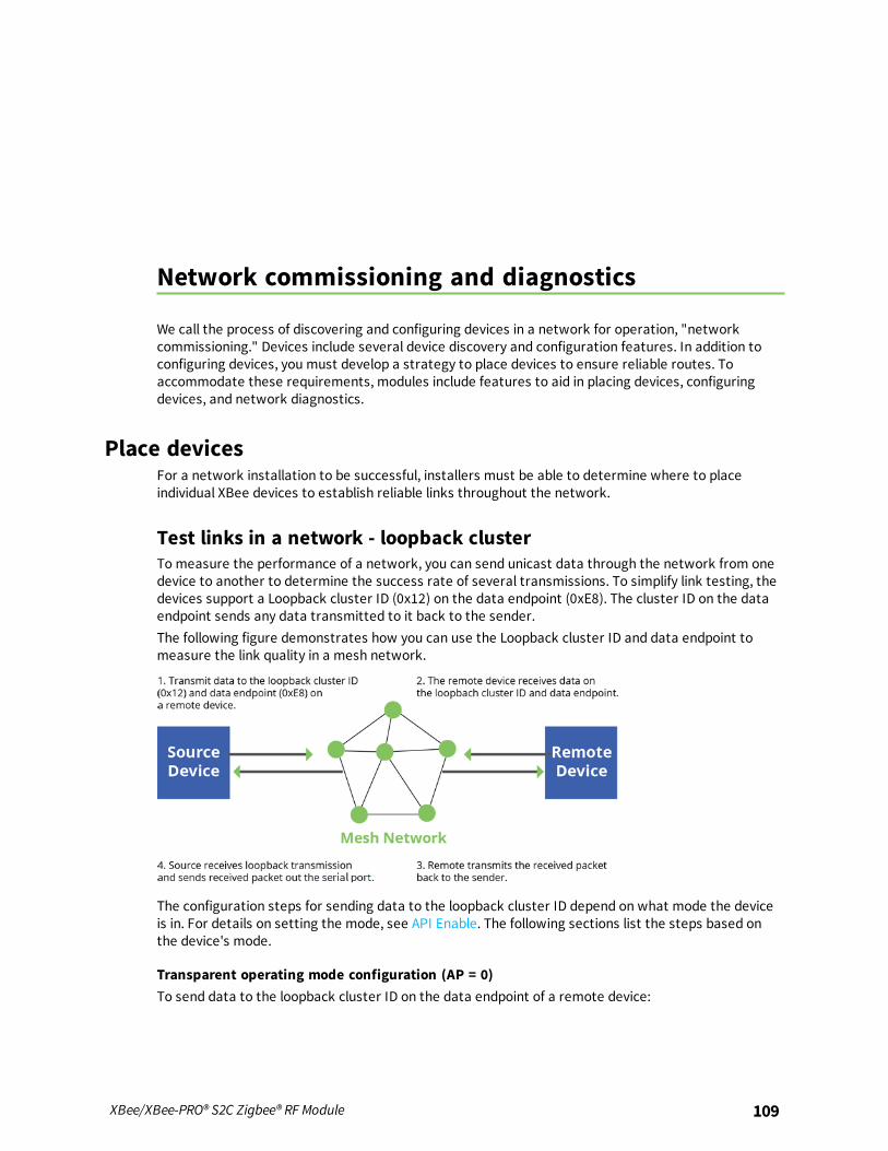
Network commissioning and diagnostics
We call the process of discovering and configuring devices in a network for operation, "networkcommissioning." Devices include several device discovery and configuration features. In addition toconfiguring devices, you must develop a strategy to place devices to ensure reliable routes. Toaccommodate these requirements, modules include features to aid in placing devices, configuringdevices, and network diagnostics.
Place devicesFor a network installation to be successful, installers must be able to determine where to placeindividual XBee devices to establish reliable links throughout the network.
Test links in a network - loopback clusterTo measure the performance of a network, you can send unicast data through the network from onedevice to another to determine the success rate of several transmissions. To simplify link testing, thedevices support a Loopback cluster ID (0x12) on the data endpoint (0xE8). The cluster ID on the dataendpoint sends any data transmitted to it back to the sender.The following figure demonstrates how you can use the Loopback cluster ID and data endpoint tomeasure the link quality in a mesh network.
The configuration steps for sending data to the loopback cluster ID depend on what mode the deviceis in. For details on setting the mode, see API Enable. The following sections list the steps based onthe device's mode.
Transparent operating mode configuration (AP = 0)To send data to the loopback cluster ID on the data endpoint of a remote device:
XBee/XBee-PRO® S2C Zigbee® RF Module 109

Network commissioning and diagnostics Device discovery
XBee/XBee-PRO® S2C Zigbee® RF Module 110
1. Set the CI command to 0x12.
2. Set the SE and DE commands to 0xE8 (default value).
3. Set the DH and DL commands to the address of the remote (0 for the coordinator, or the 64-bitaddress of the remote).
After exiting Commandmode, the device transmits any serial characters it received to the remotedevice, which returns those characters to the sending device.
API operating mode configuration (AP = 1 or AP = 2)Send an Explicit Addressing Command frame - 0x11 using 0x12 as the cluster ID and 0xE8 as both thesource and destination endpoint.The remote device echoes back the data packets it receives to the sending device.
RSSI indicatorsIt is possible to measure the received signal strength on a device using the DB command. DB returnsthe RSSI value (measured in -dBm) of the last received packet. However, this number can bemisleading in Zigbee networks. The DB value only indicates the received signal strength of the lasthop. If a transmission spans multiple hops, the DB value provides no indication of the overalltransmission path, or the quality of the worst link; it only indicates the quality of the last link.Determine the DB value in hardware using the RSSI/PWM device pin (TH pin 6/SMT pin 7). If you enablethe RSSI PWM functionality (P0 command), when the device receives data, it sets the RSSI PWM to avalue based on the RSSI of the received packet (this value only indicates the quality of the last hop).You could connect this pin to an LED to indicate if the link is stable or not.
Device discovery
Network discoveryUse the network discovery command to discover all devices that have joined a network. Issuing theND command sends a broadcast network discovery command throughout the network. All devicesthat receive the command send a response that includes:
n Device addressing information
n Node identifier string (see NI command)
n Other relevant information
You can use this command for generating a list of all module addresses in a network.
ZDO discoveryThe Zigbee device profile includes provisions to discover devices in a network that are supported on allZigbee devices (including non-Digi products). These include the LQI Request (cluster ID 0x0031) andthe Network Update Request (cluster ID 0x0038). You can use the LQI Request to read the devices inthe neighbor table of a remote device, and the Network Update Request for a remote device tocomplete an active scan to discover all nearby Zigbee devices. You can send both of these ZDOcommands using the XBee Explicit API transmit frame (0x11). For more information, see APIOperation. Refer to the Zigbee specification for formatting details of these two ZDO frames.

Network commissioning and diagnostics Commissioning pushbutton and associate LED
XBee/XBee-PRO® S2C Zigbee® RF Module 111
Joining AnnounceAll Zigbee devices send a ZDO Device Announce broadcast transmission when they join a Zigbeenetwork (ZDO cluster ID 0x0013). These frames are sent out the device's serial port as an Explicit RxIndicator API frame (0x91) if AO is set to 1. The device announce payload includes the followinginformation:[Sequence Number] + [16-bit address] + [64-bit address] + [Capability]The 16-bit and 64-bit addresses are received in little-endian byte order (LSB first). See the Zigbeespecification for details.
Commissioning pushbutton and associate LEDXBee devices support a set of commissioning pushbutton and LED behaviors to aid in devicedeployment and commissioning. These include the commissioning push button definitions andassociate LED behaviors. The following features can be supported in hardware:A pushbutton and an LED can be connected to the XBee/XBee-PRO Zigbee RF Module pins 33 and 28(SMT), or pins 20 and 15 (TH) respectively to support the commissioning pushbutton and associate LEDfunctionalities.
Commissioning pushbuttonThe commissioning pushbutton definitions provide a variety of simple functions to help with deployingdevices in a network. Enable the commissioning button functionality on pin 20 by setting D0 (AD0/DIO0Configuration) to 1 (enabled by default).
Buttonpresses Description
1 Start Joining. Wakes a sleeping end device for 30 seconds, regardless of the ST/SNsetting. It also sends node identification broadcast if joined to a network.A Zigbee device blinks a numeric error code on the Associate pin indicating the cause ofjoin failure for (AI - 32) times.A SE router or SE end device which is associated but not authenticated to a networkleaves its network; then attempt to join.
2 Enable Joining. Broadcast a Mgmt_Permit_Joining_req (ZDO ClusterID 0x0036) with TC_Significance set to 0x00.If NJ is 0x00 or 0xFF, PermitDuration is set to one minute, otherwise PermitDuration isset to NJ.
4 Restore configuration to default values and leave the network. Equivalent to issuing NR,RE, and AC commands.
Use CB command to simulate button presses in software. Issue a CB command with a parameter setto the number of button presses you want executed. For example, sending CB1 executes the actionsassociated with a single button press.The node identification frame is similar to the node discovery response frame; it contains the device’saddress, node identifier string (NI command), and other relevant data. All API devices that receive thenode identification frame send it out their serial interface as a Node Identification Indicator frame -0x95.

Network commissioning and diagnostics Commissioning pushbutton and associate LED
XBee/XBee-PRO® S2C Zigbee® RF Module 112
Associate LEDThe Associate pin (pin 28/SMT, pin 33/TH) provides an indication of the device’s network status anddiagnostics information. Connect an LED to the Associate pin as shown in the figure in Commissioningpushbutton and associate LED. Enable the Associate LED functionality the D5 command to 1 (enabledby default). If the Associate pin is enabled, it configured as an output.
Joined indicationThe Associate pin indicates the network status of a device. If the device is not joined to a network, theAssociate pin is set high. Once the device successfully joins a network, the Associate pin blinks at aregular time interval. The following figure shows the joined status of a device.
The associate pin can indicate the joined status of a device. Once the device has joined a network, theassociate pin toggles state at a regular interval (∆t). Use the LT command to set the time.The LT command defines the blink time of the Associate pin. If it is set to 0, the device uses the defaultblink time (500 ms for coordinator, 250 ms for routers and end devices).
Diagnostics supportThe Associate pin works with the commissioning pushbutton to provide additional diagnosticsbehaviors to aid in deploying and testing a network. If the commissioning push button is pressed once,and the device has not joined a network, the Associate pin blinks a numeric error code to indicate thecause of join failure. The number of blinks is equal to (AI value – 0x20). For example, if AI = 0x22, 2blinks occur.If the commissioning push button is pressed once and the device has joined a network, the devicetransmits a broadcast node identification packet. If the Associate LED functionality is enabled (D5command), a device that receives this transmission will blink its Associate pin rapidly for 1 second.The following image illustrates the behavior pressing the commissioning button press once when thedevice has not joined a network, causing the associate pin to blink to indicate the AI Code where: AI =# blinks + 0x20. In this example, AI = 0x22.
The following image illustrates the behavior pressing the button once on a remote device, causing abroadcast node identification transmission to be sent. All devices that receive this transmission blinktheir associate pin rapidly for one second if the associate LED functionality is enabled (D5 = 1).

Network commissioning and diagnostics Binding
XBee/XBee-PRO® S2C Zigbee® RF Module 113
BindingThe Digi XBee firmware supports three binding request messages:
n End Device Bind
n Bind
n Unbind
End_Device_Bind_reqThe End Device Bind request (ZDO cluster 0x0020) is described in the Zigbee Specification.During a deployment, an installer may need to bind a switch to a light. After pressing a commissioningbutton sequence on each device, this causes them to send End_Device_Bind_req messages to theCoordinator within a time window (60 s). The payload of each message is a simple descriptor whichlists input and output clusterIDs. The Coordinator matches the requests by pairing complementaryclusterIDs. After a match has been made, it sends messages to bind the devices together. When theprocess is over, both devices will have entries in their binding tables which support indirect addressingof messages between their bound endpoints.R1->C End_Device_Bind_reqR2->C End_Device_Bind_req
R1, R2 send End_Device_Bind_req within 60 s of each other to CC matches the requests.C tests one to see if binding is already in place:
R2<-C Unbind_reqR2->C Unbind-rsp (status code - NO_ENTRY)
C proceeds to create binding table entries on the two devices.R1<-C Bind_reqR1->C Bind_rspR2<-C Bind_reqR2->C Bind_rsp
C sends responses to the original End_Device_Bind_req messages.R1-<C End_Device_Bind_rspR2-<C End_Device_Bind_rsp
End Device binding sequence (binding)This message has a toggle action. If the same two devices were to subsequently send End_Device_Bind_req messages to the Coordinator, the Coordinator would detect they were already bound, andthen send Unbind_req messages to remove the binding.
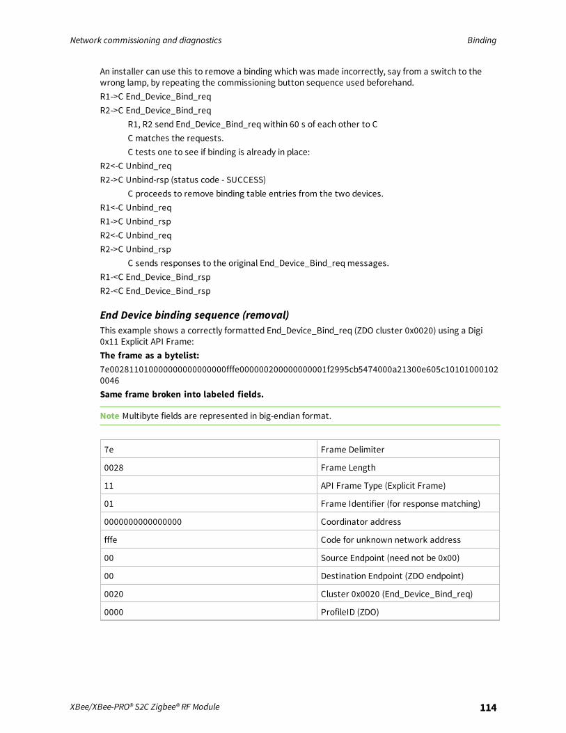
Network commissioning and diagnostics Binding
XBee/XBee-PRO® S2C Zigbee® RF Module 114
An installer can use this to remove a binding which was made incorrectly, say from a switch to thewrong lamp, by repeating the commissioning button sequence used beforehand.R1->C End_Device_Bind_reqR2->C End_Device_Bind_req
R1, R2 send End_Device_Bind_req within 60 s of each other to CC matches the requests.C tests one to see if binding is already in place:
R2<-C Unbind_reqR2->C Unbind-rsp (status code - SUCCESS)
C proceeds to remove binding table entries from the two devices.R1<-C Unbind_reqR1->C Unbind_rspR2<-C Unbind_reqR2->C Unbind_rsp
C sends responses to the original End_Device_Bind_req messages.R1-<C End_Device_Bind_rspR2-<C End_Device_Bind_rsp
End Device binding sequence (removal)This example shows a correctly formatted End_Device_Bind_req (ZDO cluster 0x0020) using a Digi0x11 Explicit API Frame:The frame as a bytelist:7e002811010000000000000000fffe000000200000000001f2995cb5474000a21300e605c101010001020046Same frame broken into labeled fields.
Note Multibyte fields are represented in big-endian format.
7e Frame Delimiter
0028 Frame Length
11 API Frame Type (Explicit Frame)
01 Frame Identifier (for response matching)
0000000000000000 Coordinator address
fffe Code for unknown network address
00 Source Endpoint (need not be 0x00)
00 Destination Endpoint (ZDO endpoint)
0020 Cluster 0x0020 (End_Device_Bind_req)
0000 ProfileID (ZDO)

Network commissioning and diagnostics Group Table API
XBee/XBee-PRO® S2C Zigbee® RF Module 115
00 Radius (default, maximum hops)
00 Transmit Options
01f2995cb5474000a21300e605c1010100010200 RFData (ZDO payload)
46 Checksum
Here is the RFData (the ZDO payload) broken into labeled fields. Note the multi-byte fields of a ZDOpayload are represented in little-endian format.
01 Transaction Sequence Number
f299 Binding Target (16 bit network address of sending device)
5cb5474000a21300 (64 bit address of sending device)
e6 Source Endpoint on sending device
05c1 ProfileID (0xC105) - used whenmatching End_Device_Bind_requests
01 Number of input clusters
0100 Input cluster ID list (0x0100)
01 Number of output clusters
0200 Output cluster ID list (0x0200)
Example of a End_Device_Bind_req
Bind_reqThe Bind request (ZDO cluster 0x0021) is described in the Zigbee Specification. A binding may be codedfor either a unicast or a multicast/groupID message.
Unbind_reqThe Unbind request (ZDO cluster 0x0022) is described in the Zigbee Specification.
Group Table APIUnlike the Binding Table that is managed with ZDO commands, a Zigbee group table is managed bythe Zigbee cluster library Groups Cluster (0x0006) with ZCL commands.The Digi Zigbee XBee firmware is intended to work with an external processor where a PublicApplication Profile with endpoints and clusters is implemented, including a Groups Cluster. Configurethe Zigbee XBee firmware to forward all ZCL commands addressed to this Group Cluster out the UART(see ATAO3). The XBee Zigbee will not use remote Groups Cluster commands to manage its ownGroup Table.But to implement multicast (group) addressing within the XBee, the external processor must keep theXBee device's group table state in sync with its own. For this reason, a Group Table API has beendefined where the external processor can manage the state of the XBee/XBee-PRO Zigbee RF Modulegroup table.
Network commissioning and diagnostics Group Table API
XBee/XBee-PRO® S2C Zigbee® RF Module 116
The design of the Group Table API of the XBee firmware derives from the ZCL Group Cluster 0x0006.Use the Explicit Addressing Command frame - 0x11 addressed to the Digi Device Object endpoint(0xE6) with the Digi XBee ProfileID (0xC105) to send commands and requests to the local device.The Zigbee home automation public application profile says groups should only be used for sets ofmore than five devices. This implies sets of five or fewer devices should be managed with multiplebinding table entries.There are five commands implemented in the API:
n Add Group command
n View group
n Get Group Membership
n Remove Group
n Remove All Groups
There is a sixth command of the Group Cluster described in the ZCL: Add Group If Identifying. Thiscommand is not supported in this API, because its implementation requires access to the IdentifyCluster, which is not maintained on the XBee. The external processor needs to implement that servercommand while using the Group Table API to keep the XBee device's group table in sync using the fivecommand primitives.
Add Group commandThe purpose of the Add Group command is to add a group table entry to associate an active endpointwith a groupID and optionally a groupName. The groupID is a two byte value. The groupName consistsof zero to 16 ASCII characters.The following example adds a group table entry which associates endpoint E7 with groupID 1234 andgroupName “ABCD”.The example packet is given in three parts, the preamble, ZCL Header, and ZCL payload:
Preamble = “11 01 “+LocalDevice64Addr+”FFFE E6 E7 0006 C105 00 00"The packet is addressed to the local node, using a source endpoint of 0xE6, clusterID of 0x0006, andprofileID of 0xC105. The destination endpoint E7 holds the endpoint parameter for the “Add Group”command.
ZCL_header = “01 ee 00"The first field (byte) is a frame control field which specifies a Cluster Specific command (0x01) using aClient->Server direction(0x00). The second field is a transaction sequence number used to associatethe response with the command request. The third field is the command identifier for “Add Group”(0x00).
ZCL_payload = “3412 04 41 42 43 44"The first two bytes is the group Id to add in little endian representation. The next byte is the stringname length (00 if there is no string). The other bytes are the descriptive ASCII string name (“ABCD”)for the group table entry. The string is represented with its length in the first byte, and the otherbytes containing the ASCII characters.The example packet in raw hex byte form:
7e001e11010013a2004047b55cfffee6e70006c105000001ee0034120441424344c7The response in raw hex byte form, consisting of two packets:
7e0018910013a2004047b55cfffee7e68006c1050009ee00003412387e00078b01fffe00000076
The response in decoded form:
Network commissioning and diagnostics Group Table API
XBee/XBee-PRO® S2C Zigbee® RF Module 117
Zigbee Explicit Rx IndicatorAPI 0x91 64DestAddr 0x0013A2004047B55C 16DestAddr 0xFFFE SrcEP 0xE7 DestEP 0xE6ClusterID 0x8006 ProfileID 0xC105 Options 0x00RF_Data 0x09EE00003412
The response in terms of Preamble, ZCL Header, and ZCL payload:Preamble = “910013a2004047b55cfffee7e68006c10500”
The packet has its endpoint values reversed from the request, and the clusterID is 0x8006 indicating aGroup cluster response.
ZCL_header = “09 ee 00"The first field is a frame control field which specifies a Cluster Specific command (0x01) using a Server-> Client direction. The second field is a transaction sequence number used to associate the responsewith the command request. The third field is the command identifier “Add Group” (0x00).
ZCL_payload = “00 3412"The first byte is a status byte (SUCCESS=0x00). The next two bytes hold the group ID (0x1234) in littleendian form.This is the decoded secondmessage, which is a Tx Status for the original command request. If theFrameId value in the original command request had been zero, or if no space was available in thetransmit UART buffer, then no Tx Status message occurs.
Zigbee Tx StatusAPI 0x8B FrameID 0x01 16DestAddr 0xFFFETransmit Retries 0x00 Delivery Status 0x00 Discovery Status 0x00 Success
View groupThe purpose of the View Group command is to get the name string which is associated with aparticular endpoint and groupID.The following example gets the name string associated with the endpoint E7 and groupID 1234.The packet:
Preamble = “11 01 “+LocalDevice64Addr+”FFFE E6 E7 0006 C105 00 00"
The packet is addressed to the local node, using a source endpoint of 0xE6, clusterID of 0x0006, andprofileID of 0xC105. The destination endpoint E7 is the endpoint parameter for the “View Group”command.
ZCL_header = “01 ee 01"
The first field is a frame control field which specifies a Cluster Specific command (0x01) using a Client->Server direction(0x00). The second field is a transaction sequence number which is used to associatethe response with the command request. The third field is the command identifier “View Group”(0x01) .
ZCL_payload = “3412”
The two byte value is the groupID in little-endian representation.The packet in raw hex byte form:
7e001911010013a2004047b55cfffee6e70006c105000001ee013412d4
The response in raw hex byte form, consisting of two packets:

Network commissioning and diagnostics Group Table API
XBee/XBee-PRO® S2C Zigbee® RF Module 118
7e001d910013a2004047b55cfffee7e68006c1050009ee010034120441424344247e00078b01fffe00000076
The command response in decoded form:
Zigbee Explicit Rx IndicatorAPI 0x91 64DestAddr 0x0013A2004047B55C 16DestAddr 0xFFFE SrcEP 0xE7 DestEP 0xE6ClusterID 0x8006 ProfileID 0xC105 Options 0x00RF_Data 0x09EE010034120441424344
The response in terms of Preamble, ZCL Header, and ZCL payload:
Preamble = “910013a2004047b55cfffee7e68006c10500”
The packet has its endpoint values reversed from the request, and the clusterID is 0x8006 indicating aGroup cluster response.
ZCL_header = “09 ee 01"
The first field is a frame control field which specifies a Cluster Specific command (0x01) using a Server->Client direction (0x08). The second field is a transaction sequence number which associates theresponse with the command request. The third field is the command identifier “View Group” (0x01) .
ZCL_payload = “00 3412 0441424344"
The first byte is a status byte (SUCCESS=0x00). The next two bytes hold the groupID (0x1234) in little-endian form. The next byte is the name string length (0x04). The remaining bytes are the ASCII namestring characters (“ABCD”).The following is the decoded secondmessage, which is a Tx Status for the original command request.If the FrameId value in the original command request had been zero, or if no space was available inthe transmit UART buffer, then no Tx Status message would occur.
Zigbee Tx StatusAPI 0x8B FrameID 0x01 16DestAddr 0xFFFTransmit Retries 0x00 Delivery Status 0x00 Discovery Status 0x00 Success
Get Group Membership
Get Group Membership (1 of 2)The purpose of this first form of the Get Group Membership command is to get all the groupIDsassociated with a particular endpoint.The intent of the example is to get all the groupIDs associated with endpoint E7.The example packet is given in three parts, the preamble, ZCL Header, and ZCL payload:
Preamble = “11 01 “+LocalDevice64Addr+”FFFE E6 E7 0006 C105 00 00"
The packet is addressed to the local node, using a source endpoint of 0xE6, clusterID of 0x0006, andprofileID of 0xC105. The destination endpoint E7 holds the endpoint parameter for the “Get GroupMembership” command.
ZCL_header = “01 ee 02"
The first field (byte) is a frame control field which specifies a Cluster Specific command (0x02) using aClient->Server direction(0x00). The second field is a transaction sequence number which is used to
Network commissioning and diagnostics Group Table API
XBee/XBee-PRO® S2C Zigbee® RF Module 119
associate the response with the command request. The third field is the command identifier for “GetGroup Membership” (0x02) .
ZCL_payload = “00”
The first byte is the group count. If it is zero, then all groupIDs with an endpoint value which matchesthe given endpoint parameter will be returned in the response.The example packet in raw hex byte form:
7e001811010013a2004047b55cfffee6e70006c105000001ee020019
The response in raw hex byte form, consisting of two packets:
7e0019910013a2004047b55cfffee7e68006c1050009ee02ff01341235
7e00078b01fffe00000076
The response in decoded form:
Zigbee Explicit Rx IndicatorAPI 0x91 64DestAddr 0x0013A2004047B55C 16DestAddr 0xFFFE SrcEP 0xE7 DestEP 0xE6ClusterID 0x8006 ProfileID 0xC105 Options 0x00RF_Data 0x09EE02FF013412
The response in terms of Preamble, ZCL Header, and ZCL Payload:
Preamble = “910013a2004047b55cfffee7e68006c10500”
The packet has the endpoints reversed from the request, and the clusterID is 0x8006 indicating aGroup cluster response.
ZCL_header = “09 ee 02"
The first field is a frame control field which specifies a Cluster Specific command (0x01) using a Server->Client direction (0x08). The second field is a transaction sequence number which is used to associatethe response with the command request. The third field is the command identifier “Get GroupMembership” (0x02) .
ZCL_payload = “FF 01 3412"
The first byte is the remaining capacity of the group table. 0xFF means unknown. The XBee returnsthis value because the capacity of the group table is dependent on the remaining capacity of thebinding table, thus the capacity of the group table is unknown. The second byte is the group count(0x01). The remaining bytes are the groupIDs in little-endian representation.The following is the decoded secondmessage, which is a Tx Status for the original command request.If the FrameId value in the original command request had been zero, or if no space was available inthe transmit UART buffer, then no Tx Status message would occur.
Zigbee Tx StatusAPI 0x8B FrameID 0x01 16DestAddr 0xFFFETransmit Retries 0x00 Delivery Status 0x00 Discovery Status 0x00 Success
Get Group Membership (2 of 2)The purpose of this second form of the Get Group Membership command is to get the set of groupIDsassociated with a particular endpoint which are a subset of a list of given groupIDs.
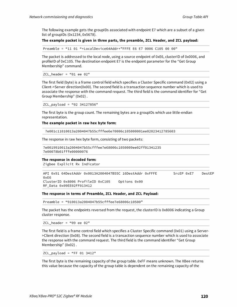
Network commissioning and diagnostics Group Table API
XBee/XBee-PRO® S2C Zigbee® RF Module 120
The following example gets the groupIDs associated with endpoint E7 which are a subset of a givenlist of groupIDs (0x1234, 0x5678).The example packet is given in three parts, the preamble, ZCL Header, and ZCL payload:
Preamble = “11 01 “+LocalDevice64Addr+”FFFE E6 E7 0006 C105 00 00"
The packet is addressed to the local node, using a source endpoint of 0xE6, clusterID of 0x0006, andprofileID of 0xC105. The destination endpoint E7 is the endpoint parameter for the “Get GroupMembership” command.
ZCL_header = “01 ee 02"
The first field (byte) is a frame control field which specifies a Cluster Specific command (0x02) using aClient->Server direction(0x00). The second field is a transaction sequence number which is used toassociate the response with the command request. The third field is the command identifier for “GetGroup Membership” (0x02) .
ZCL_payload = “02 34127856"
The first byte is the group count. The remaining bytes are a groupIDs which use little-endianrepresentation.The example packet in raw hex byte form:
7e001c11010013a2004047b55cfffee6e70006c105000001ee02023412785603
The response in raw hex byte form, consisting of two packets:
7e0019910013a2004047b55cfffee7e68006c1050009ee02ff013412357e00078b01fffe00000076
The response in decoded form:Zigbee Explicit Rx Indicator
API 0x91 64DestAddr 0x0013A2004047B55C 16DestAddr 0xFFFE SrcEP 0xE7 DestEP0xE6ClusterID 0x8006 ProfileID 0xC105 Options 0x00RF_Data 0x09EE02FF013412
The response in terms of Preamble, ZCL Header, and ZCL Payload:
Preamble = “910013a2004047b55cfffee7e68006c10500”
The packet has the endpoints reversed from the request, the clusterID is 0x8006 indicating a Groupcluster response.
ZCL_header = “09 ee 02"
The first field is a frame control field which specifies a Cluster Specific command (0x01) using a Server->Client direction (0x08). The second field is a transaction sequence number which is used to associatethe response with the command request. The third field is the command identifier “Get GroupMembership” (0x02) .
ZCL_payload = “FF 01 3412"
The first byte is the remaining capacity of the group table. 0xFF means unknown. The XBee returnsthis value because the capacity of the group table is dependent on the remaining capacity of the

Network commissioning and diagnostics Group Table API
XBee/XBee-PRO® S2C Zigbee® RF Module 121
binding table, thus the capacity of the group table is unknown. The second byte is the group count(0x01). The remaining bytes are the groupIDs in little-endian representation.The following is the decoded secondmessage, which is a Tx Status for the original command request.If the FrameId value in the original command request had been zero, or if no space was available inthe transmit UART buffer, then no Tx Status message occurs.
Zigbee Tx StatusAPI 0x8B FrameID 0x01 16DestAddr 0xFFFETransmit Retries 0x00 Delivery Status 0x00 Discovery Status 0x00 Success
Remove GroupThe purpose of the Remote Group command is to remove a Group Table entry which associates agiven endpoint with a given groupID.The intent of the example is to remove the association of groupID [TBD] with endpoint E7.The example packet is given in three parts: the preamble, ZCL Header, and ZCL payload.
Preamble = “11 01 “+LocalDevice64Addr+”FFFE E6 E7 0006 C105 00 00"
The packet is addressed to the local node, using a source endpoint of 0xE6, clusterID of 0x0006, andprofileID of 0xC105. The destination endpoint E7 is the endpoint parameter for the “Remove Group”command.
ZCL_header = “01 ee 03"
The first field is a frame control field which specifies a Cluster Specific command (0x01) using a Client->Server direction(0x00). The second field is a transaction sequence number which is used to associatethe response with the command request. The third field is the command identifier “Remove Group”(0x03) .
ZCL_payload = “3412”
The two bytes value is the groupID to be removed in little-endian representation.The packet in raw hex byte form:
7e001911010013a2004047b55cfffee6e70006c105000001ee033412d2
The response in raw hex byte form, consisting of two packets:
7e0018910013a2004047b55cfffee7e68006c1050009ee03003412357e00078b01fffe00000076
The command response in decoded form:
Zigbee Explicit Rx IndicatorAPI 0x91 64DestAddr 0x0013A2004047B55C 16DestAddr 0xFFFE SrcE 0xE DestEP 0xE6ClusterID 0x8006 ProfileID 0xC105 Options 0x00RF_Data 0x09EE03003412
The response in terms of Preamble, ZCL Header, and ZCL payload:
Preamble = “910013a2004047b55cfffee7e68006c10500”
The packet has its endpoint values reversed from the request, and the clusterID is 0x8006 indicating aGroup cluster response.
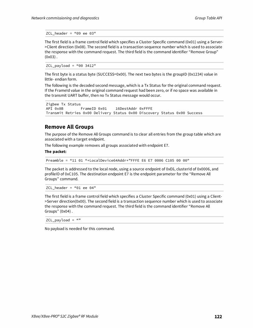
Network commissioning and diagnostics Group Table API
XBee/XBee-PRO® S2C Zigbee® RF Module 122
ZCL_header = “09 ee 03"
The first field is a frame control field which specifies a Cluster Specific command (0x01) using a Server->Client direction (0x08). The second field is a transaction sequence number which is used to associatethe response with the command request. The third field is the command identifier “Remove Group”(0x03) .
ZCL_payload = “00 3412"
The first byte is a status byte (SUCCESS=0x00). The next two bytes is the groupID (0x1234) value inlittle- endian form.The following is the decoded secondmessage, which is a Tx Status for the original command request.If the FrameId value in the original command request had been zero, or if no space was available inthe transmit UART buffer, then no Tx Status message would occur.
Zigbee Tx StatusAPI 0x8B FrameID 0x01 16DestAddr 0xFFFETransmit Retries 0x00 Delivery Status 0x00 Discovery Status 0x00 Success
Remove All GroupsThe purpose of the Remove All Groups command is to clear all entries from the group table which areassociated with a target endpoint.The following example removes all groups associated with endpoint E7.The packet:
Preamble = “11 01 “+LocalDevice64Addr+”FFFE E6 E7 0006 C105 00 00"
The packet is addressed to the local node, using a source endpoint of 0xE6, clusterId of 0x0006, andprofileID of 0xC105. The destination endpoint E7 is the endpoint parameter for the “Remove AllGroups” command.
ZCL_header = “01 ee 04"
The first field is a frame control field which specifies a Cluster Specific command (0x01) using a Client->Server direction(0x00). The second field is a transaction sequence number which is used to associatethe response with the command request. The third field is the command identifier “Remove AllGroups” (0x04) .
ZCL_payload = “”
No payload is needed for this command.

Network commissioning and diagnostics Group Table API
XBee/XBee-PRO® S2C Zigbee® RF Module 123
The packet in raw hex byte form:
7e001711010013a2004047b55cfffee6e70006c105000001ee0417
The response in raw hex byte form, consisting of two packets:
7e0016910013a2004047b55cfffee7e68006c1050009ee04007c7e00078b01fffe00000076
The command response in decoded form:
Zigbee Explicit Rx IndicatorAPI 0x91 64DestAddr 0x0013A2004047B55C 16DestAddr 0xFFFE SrcEP 0xE7 DestEP0xE6ClusterID 0x8006 ProfileID 0xC105 Options 0x00RF_Data 0x09ee0400
The response in terms of Preamble, ZCL Header, and ZCL payload.
Preamble = “910013a2004047b55cfffee7e68006c10500”
The packet has its endpoints values reversed from the request, and the clusterID is 0x8006 indicatinga Group cluster response.
ZCL_header = “09 ee 04"
The first field is a frame control field which specifies a Cluster Specific command (0x01) using a Server->Client direction (0x08). The second field is a transaction sequence number which is used to associatethe response with the command request. The third field is the command identifier “Remove AllGroups” (0x04) .
ZCL_payload = “00”
The first byte is a status byte (SUCCESS=0x00)[4].And here is the decoded secondmessage, which is a Tx Status for the original command request. Ifthe FrameID value in the original command request had been zero, or if no space was available in thetransmit UART buffer, then no Tx Status message would occur.
Zigbee Tx StatusAPI 0x8B FrameID 0x01 16DestAddr 0xFFFETransmit Retries 0x00 Delivery Status 0x00 Discovery Status 0x00 Success
Default responsesMany errors are returned as a default response. For example, an RFData payload of a responsecontaining 08010b788b would be decoded as:
ZCL_header = “08 01 03" - general command/server-to-client, transseqnum=1,default_response_command(0x03)ZCL_payload = “78 8b” - original cmdID, status code (0x8b)EMBER_ZCL_STATUS_NOT_FOUND
Common status codesThis section lists some of the more frequently occurring status codes.

Network commissioning and diagnostics Group Table API
XBee/XBee-PRO® S2C Zigbee® RF Module 124
0x00 EMBER_ZCL_STATUS_SUCCESS: Command request was successful0x01 EMBER_ZCL_STATUS_FAILURE: Command request failed - for example,a call to remove an entry from the group table returned an error0x80 EMBER_ZCL_STATUS_MALFORMED_COMMAND: no RFData in the API frame;ZCL Payload appears truncated from what is expected0x81 EMBER_ZCL_STATUS_UNSUP_CLUSTER_COMMAND: unexpected directionin the Frame Control Field of the ZCL Header; unexpected command identifier codevaluein the ZCL header0x82 EMBER_ZCL_STATUS_UNSUP_GENERAL_COMMAND: unexpected frametypein the Frame Control Field of the ZCL Header0x84 EMBER_ZCL_STATUS_UNSUP_MANUF_GENERAL_COMMAND: unexpectedmanufacturer specific indication in the Frame Control Field of the ZCL Header0x8b EMBER_ZCL_STATUS_NOT_FOUND: An attempt at Get Group Membership orRemove Group could not find a matching entry in the group table

Manage End Devices
Zigbee end devices are intended to be battery-powered devices capable of sleeping for extendedperiods of time. Since end devices may not be awake to receive RF data at a given time, routers andcoordinators are equipped with additional capabilities (including packet buffering and extendedtransmission timeouts) to ensure reliable data delivery to end devices.
End device operation 126Parent operation 126Non-Parent device operation 128End Device configuration 128Recommended sleep current measurements 135Transmit RF data 136Receiving RF data 136I/O sampling 137Wake end devices with the Commissioning Pushbutton 137Parent verification 137Rejoining 137Router/Coordinator configuration 138Short sleep periods 139Extended sleep periods 139Sleep examples 139
XBee/XBee-PRO® S2C Zigbee® RF Module 125
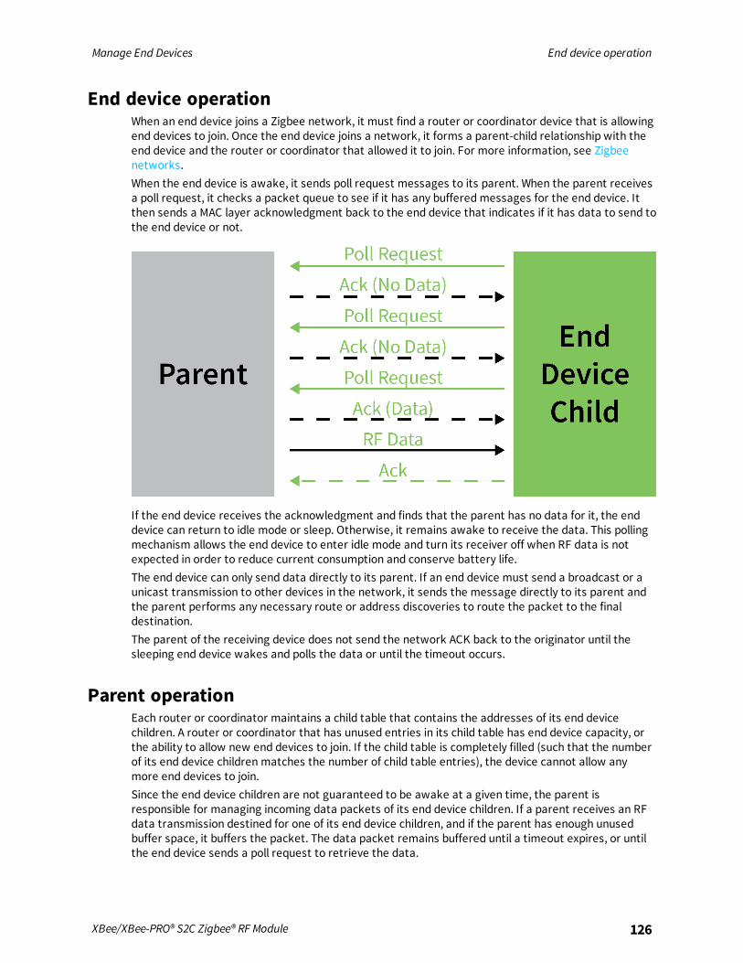
Manage End Devices End device operation
XBee/XBee-PRO® S2C Zigbee® RF Module 126
End device operationWhen an end device joins a Zigbee network, it must find a router or coordinator device that is allowingend devices to join. Once the end device joins a network, it forms a parent-child relationship with theend device and the router or coordinator that allowed it to join. For more information, see Zigbeenetworks.When the end device is awake, it sends poll request messages to its parent. When the parent receivesa poll request, it checks a packet queue to see if it has any bufferedmessages for the end device. Itthen sends a MAC layer acknowledgment back to the end device that indicates if it has data to send tothe end device or not.
If the end device receives the acknowledgment and finds that the parent has no data for it, the enddevice can return to idle mode or sleep. Otherwise, it remains awake to receive the data. This pollingmechanism allows the end device to enter idle mode and turn its receiver off when RF data is notexpected in order to reduce current consumption and conserve battery life.The end device can only send data directly to its parent. If an end device must send a broadcast or aunicast transmission to other devices in the network, it sends the message directly to its parent andthe parent performs any necessary route or address discoveries to route the packet to the finaldestination.The parent of the receiving device does not send the network ACK back to the originator until thesleeping end device wakes and polls the data or until the timeout occurs.
Parent operationEach router or coordinator maintains a child table that contains the addresses of its end devicechildren. A router or coordinator that has unused entries in its child table has end device capacity, orthe ability to allow new end devices to join. If the child table is completely filled (such that the numberof its end device children matches the number of child table entries), the device cannot allow anymore end devices to join.Since the end device children are not guaranteed to be awake at a given time, the parent isresponsible for managing incoming data packets of its end device children. If a parent receives an RFdata transmission destined for one of its end device children, and if the parent has enough unusedbuffer space, it buffers the packet. The data packet remains buffered until a timeout expires, or untilthe end device sends a poll request to retrieve the data.

Manage End Devices Parent operation
XBee/XBee-PRO® S2C Zigbee® RF Module 127
The parent can buffer one broadcast transmission for all of its end device children. When the parentreceives and buffers a broadcast transmission, it sets a flag in its child table when each child polls andretrieves the packet. Once all children have received the broadcast packet, the parent discards thebuffered broadcast packet. If all children have not received a buffered broadcast packet and theparent receives a new broadcast, it discards the old broadcast packet, clears the child table flags, andbuffers the new broadcast packet for the end device children as shown in the following figure.
When an end device sends data to its parent that is destined for a remote device in the network, theparent buffers the data packet until it can establish a route to the destination. The parent mayperform a route or 16-bit address discovery of its end device children. Once a route is established, theparent sends the data transmission to the remote device.
End Device poll timeoutsTo better support mobile end devices (end devices that can move within a network), parent routerand coordinator devices have a poll timeout for each end device child. If an end device does not send apoll request to its parent within the poll timeout, the parent removes the end device from its childtable. This allows the child table on a router or coordinator to better accommodate mobile enddevices in the network.
Packet buffer usagePacket buffer usage on a router or coordinator varies depending on the application. The followingactivities can require use of packet buffers for up to several seconds:
n Route and address discoveries
n Application broadcast transmissions
n Stack broadcasts (for example ZDO “Device Announce” messages when devices join a network)
n Unicast transmissions buffered until acknowledgment is received from destination or retriesexhausted
n Unicast messages waiting for end device to wake
Applications that use regular broadcasting or that require regular address or route discoveries use upa significant number of buffers, reducing the buffer availability for managing packets for end devicechildren. Applications can reduce the number of required application broadcasts, and considerimplementing an external address table or many-to-one and source routing if necessary to improverouting efficiency.

Manage End Devices Non-Parent device operation
XBee/XBee-PRO® S2C Zigbee® RF Module 128
Non-Parent device operationDevices in the Zigbee network treat data transmissions to end devices differently than transmissionsto other routers and coordinators. When a device sends a unicast transmission, if it does not receive anetwork acknowledgment within a timeout, the device resends the transmission. When transmittingdata to remote coordinator or router devices, the transmission timeout is relatively short since thesedevices are powered and responsive.However, since end devices may sleep for some time, unicast transmissions to end devices use anextended timeout mechanism in order to allow enough time for the end device to wake and receivethe data transmission from its parent.If a non-parent device does not know the destination is an end device, it uses the standard unicasttimeout for the transmission. However, provisions exist in the Ember Zigbee stack for the parent toinform the message sender that the destination is an end device. Once the sender discovers thedestination device is an end device, future transmissions will use the extended timeout. For moreinformation see Router/Coordinator configuration.
End Device configurationXBee end devices support three different sleepmodes:
n Pin sleep
n Cyclic sleep
n Cyclic sleep with pin wake-up
Pin sleep allows an external microcontroller to determine when the XBee/XBee-PRO Zigbee RFModule sleeps and when it wakes by controlling the Sleep_RQ pin. In contrast, cyclic sleep allows thesleep period and wake times to be configured through the use of AT commands. Cyclic sleep with pinwake-up is the same as cyclic sleep except the device can be awakened before the sleep periodexpires by lowering the SLEEP_RQ line. The SM command configures the sleepmode.In both pin and cyclic sleepmodes, XBee end devices poll their parent every 100 ms while they areawake to retrieve buffered data. When the end device sends a poll request, it enables the receiveruntil it receives an acknowledgment from the parent. It typically takes less than 10 ms betweensending the poll request to receiving the acknowledgment. The acknowledgment indicates if theparent has buffered data for the end device child. If the acknowledgment indicates the parent haspending data, the end device leaves the receiver on to receive the data. Otherwise, the end deviceturns off the receiver and enter idle mode (until it sends the next poll request) to reduce currentconsumption (and improve battery life).Once the device enters sleepmode, the On/Sleep pin (TH pin 13/SMT pin 26) it de-asserts (low) toindicate the device is entering sleepmode. If the device enables CTS hardware flow control (D7command), it de-asserts (high) the CTS pin (TH pin 12/SMT pin 25) when entering sleep to indicatethat serial data should not be sent to the device.If the Associate LED pin is configured (D5 command), the associate pin is driven low to avoid usingpower to light the LED. The Sleep_Rq pin is configured as a pulled-down input so that an externaldevice must drive it low to wake the device. All other pins are left unmodified during sleep so that theycan operate as previously configured by the user. The device does not respond to serial or RF datawhen it is sleeping.Applications that must communicate serially to sleeping end devices are encouraged to observe CTSflow control.When the device wakes from sleep, it asserts (high) the On/Sleep pin, and if it enables flow control, italso asserts (low) the CTS pin. The associate LED and all other pins resume their former configured

Manage End Devices End Device configuration
XBee/XBee-PRO® S2C Zigbee® RF Module 129
operation. If the device has not joined a network, it scans all SC channels after waking to try and find avalid network to join.
Pin sleepPin sleep allows the module to sleep and wake according to the state of the SLEEP_RQ pin (TH pin9/SMT pin 10). Pin sleepmode is enabled by setting the SM command to 1.When the device asserts (high) SLEEP_RQ, it finishes any transmit or receive operations for thecurrent packet that is processing and enters a low power state. For example, if the device has notjoined a network and SLEEP_RQ is asserted (high), it sleeps once the current join attempt completes(that is, when scanning for a valid network completes). The device wakes from pin sleep when theSLEEP_RQ pin is de-asserted (low). The following figures show the device's sleep pins.
Surface-mount sleep pins

Manage End Devices End Device configuration
XBee/XBee-PRO® S2C Zigbee® RF Module 130
Through-hole sleep pins
The following figure show the pin sleep waveforms:
In the previous figure, t1, t2, t3 and t4 represent the following events:n t1 - Time when Sleep_RQ is asserted (high)
n t2 - Time when the device enters sleep (CTS state change only if hardware flow control isenabled)
n t3 - Time when Sleep_RQ is de-asserted (low) and the device wakes
n t4 - Time when the module sends a poll request to its parent
The time between t1 and t2 varies depending on the state of the module. In the worst case scenario,if the end device is trying to join a network, or if it is waiting for an acknowledgment from a datatransmission, the delay could be up to a few seconds. The time between t3 and t4 is 1-2 ms for aregular device and about 6 ms for a PRO device.
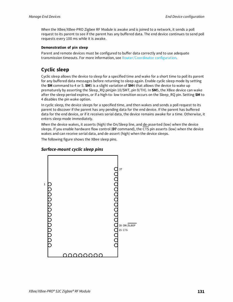
Manage End Devices End Device configuration
XBee/XBee-PRO® S2C Zigbee® RF Module 131
When the XBee/XBee-PRO Zigbee RF Module is awake and is joined to a network, it sends a pollrequest to its parent to see if the parent has any buffered data. The end device continues to send pollrequests every 100 ms while it is awake.
Demonstration of pin sleepParent and remote devices must be configured to buffer data correctly and to use adequatetransmission timeouts. For more information, see Router/Coordinator configuration.
Cyclic sleepCyclic sleep allows the device to sleep for a specified time and wake for a short time to poll its parentfor any buffered data messages before returning to sleep again. Enable cyclic sleepmode by settingthe SM command to 4 or 5. SM5 is a slight variation of SM4 that allows the device to wake upprematurely by asserting the Sleep_RQ pin(pin 10/SMT, pin 9/TH). In SM5, the XBee device can wakeafter the sleep period expires, or if a high-to- low transition occurs on the Sleep_RQ pin. Setting SM to4 disables the pin wake option.In cyclic sleep, the device sleeps for a specified time, and then wakes and sends a poll request to itsparent to discover if the parent has any pending data for the end device. If the parent has buffereddata for the end device, or if it receives serial data, the device remains awake for a time. Otherwise, itenters sleepmode immediately.When the device wakes, it asserts (high) the On/Sleep line, and de-asserted (low) when the devicesleeps. If you enable hardware flow control (D7 command), the CTS pin asserts (low) when the devicewakes and can receive serial data, and de-assert (high) when the device sleeps.The following figure shows the XBee sleep pins.
Surface-mount cyclic sleep pins
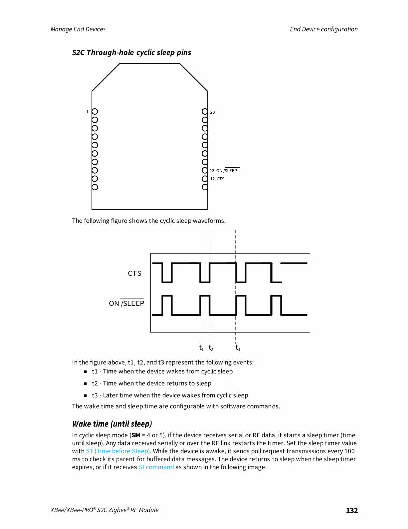
Manage End Devices End Device configuration
XBee/XBee-PRO® S2C Zigbee® RF Module 132
S2C Through-hole cyclic sleep pins
The following figure shows the cyclic sleep waveforms.
In the figure above, t1, t2, and t3 represent the following events:n t1 - Time when the device wakes from cyclic sleep
n t2 - Time when the device returns to sleep
n t3 - Later time when the device wakes from cyclic sleep
The wake time and sleep time are configurable with software commands.
Wake time (until sleep)In cyclic sleepmode (SM = 4 or 5), if the device receives serial or RF data, it starts a sleep timer (timeuntil sleep). Any data received serially or over the RF link restarts the timer. Set the sleep timer valuewith ST (Time before Sleep). While the device is awake, it sends poll request transmissions every 100ms to check its parent for buffered data messages. The device returns to sleep when the sleep timerexpires, or if it receives SI command as shown in the following image.

Manage End Devices End Device configuration
XBee/XBee-PRO® S2C Zigbee® RF Module 133
Sleep periodConfigure the sleep period based on the SP, SN, and SO commands. The following table lists thebehavior of these commands.
Command Range Description
SP 0x20 - 0xAF0 (x 10 ms)(320 - 28,000 ms)
Configures the sleep period of the device.
SN 1 - 0xFFFF Configures the number of sleep periods multiplier.
SO 0 - 0xFF Defines options for sleepmode behavior.0x02 - Always wake for full ST time0x04 - Enable extended sleep (sleep for full (SP * SN) time)
The device supports both a Short cyclic sleep and an Extended cyclic sleep that make use of thesecommands. These two modes allow the sleep period to be configured according to the applicationrequirements.
Short cyclic sleepIn short cyclic sleepmode, define the sleep behavior of the device by the SP and SN commands, andthe SO commandmust be set to 0x00 (default) or 0x02. In short cyclic sleepmode, the SP commanddefines the sleep period and you can set it for up to 28 seconds. When the device enters short cyclicsleep, it remains in a low power state until the SP time has expired.After the sleep period expires, the XBee/XBee-PRO Zigbee RF Module sends a poll requesttransmission to its parent to determine if the parent has any buffered data waiting for the end device.Since router and coordinator devices can buffer data for end device children up to 30 seconds, the SPrange (up to 28 seconds) allows the end device to poll regularly enough to receive buffered data. If theparent has data for the end device, the end device starts its sleep timer (ST) and continues pollingevery 100 ms to receive data. If the end device wakes and finds that its parent has no data for it, theend device can return to sleep immediately.Use the SN command to control when the On/Sleep line is asserted (high). If you SN to 1 (default), theOn/Sleep line sets high each time the device wakes from sleep. Otherwise, if SN is greater than 1, theOn/ Sleep line only sets high if RF data is received, or after SN wake cycles occur. This allows anexternal device to remain powered off until it receives RF data, or until a number of sleep periods haveexpired (SN sleep periods). This mechanism allows the device to wake at regular intervals to poll its

Manage End Devices End Device configuration
XBee/XBee-PRO® S2C Zigbee® RF Module 134
parent for data without waking an external device for an extended time (SP * SN time) as shown inthe following figure.
Note SP controls the packet buffer time on routers and coordinators. Set SP on all router andcoordinator devices to match the longest end device SP time. For more information, seeRouter/Coordinator configuration.
Extended cyclic sleepIn extended cyclic sleep operation, an end device can sleep for a multiple of SP time which can extendthe sleep time up to several days. Configure the sleep period using the SP and SN commands. Thetotal sleep period is equal to (SP * SN) where SP is measured in 10ms units. The SO commandmust beset correctly to enable extended sleep.Since routers and coordinators can only buffer incoming RF data for their end device children for up to30 seconds, if an end device sleeps longer than 30 seconds, devices in the network need someindication when an end device is awake before they can send data to it. End devices that use extendedcyclic sleep should send a transmission (such as an I/O sample) when they wake to inform otherdevices that they are awake and can receive data. We recommended that extended sleep end devicesset SO to wake for the full ST time to provide other devices with enough time to sendmessages to theend device.Similar to short cyclic sleep, end devices running in this mode return to sleep when the sleep timerexpires, or when they receive the SI command.
Deep sleepThe following are preconditions for maintaining low current draw during sleep:
n You must maintain the supply voltage within a valid operating range (2.1 to 3.6 V for the XBee,3.0 to 3.6 V for the XBee-PRO (S2), 2.7 to 3. V for the XBee-PRO S2B).
n Each GPIO input line with a pullup resistor which is driven low draws about 100 uA currentthrough the internal pullup resistor.

Manage End Devices Recommended sleep current measurements
XBee/XBee-PRO® S2C Zigbee® RF Module 135
n If circuitry external to the XBee drives such input lines low, then the current draw rises aboveexpected deep sleep levels.
n Each GPIO input line that has no pullup or pull-down resistor (is floating) has an indeterminatevoltage which can change over time and temperature in an indeterminate manner.
Recommended sleep current measurementsProperly measuring the sleep current helps to accurately estimate battery life requirements. Toensure that you take proper measurements without upsetting the normal operation of the unit undertest, read the following steps.When you measure sleep currents, it can cause problems with the devices because the equipmentthat measures very low currents accurately requires a large resistor in series with the power supply.This large resistor starves current from the device during a momentary wake cycle, forcing thevoltage to drop to brownout levels rapidly. This voltage drop places the device in a state that mayrequire a reset to resolve the problem.
Achieve the lowest sleep currentTo achieve the lowest sleep current, you must disable brownout detectors during sleepmodes. Even ifthe measurement equipment automatically changes current ranges, it is often too slow and cannotkeep up with the necessary sudden short bursts. During long cyclic sleep periods, the device can wakeevery 10 to 30 seconds to reset timers and perform other necessary steps. These wake times aresmall and you may not notice them whenmeasuring sleep currents.
Compensate for switching timeTo compensate for the switching time of the equipment you must temporarily add an additional largecap when you needmeasurements to allow for short pulses of current draw (see the followingschematic for details). A cap of 100 uF is enough to handle 1.5 milliseconds with 20 mA of current. Youcan increase or decrease the capacitor based on the switching time of the measurement circuitry andthe momentary on time of the unit. Measure the leakage current of the additional cap to verify that itdoes not skew the low current reading. The capacitor averages the spike in current draw. The actualmagnitude of the current spike is no longer visible, but you can account for the total energy consumedby integrating the current over time andmultiplying by the voltage.The sleep current may be less for an S2C than an S2D, because the S2D has more RAM to maintainduring sleep (64K versus 12K RAM).
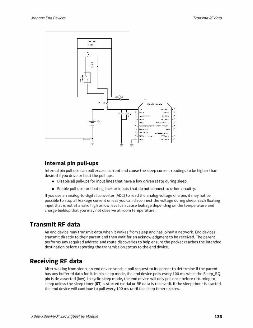
Manage End Devices Transmit RF data
XBee/XBee-PRO® S2C Zigbee® RF Module 136
Internal pin pull-upsInternal pin pull-ups can pull excess current and cause the sleep current readings to be higher thandesired if you drive or float the pull-ups.
n Disable all pull-ups for input lines that have a low driven state during sleep.
n Enable pull-ups for floating lines or inputs that do not connect to other circuitry.
If you use an analog-to-digital converter (ADC) to read the analog voltage of a pin, it may not bepossible to stop all leakage current unless you can disconnect the voltage during sleep. Each floatinginput that is not at a valid high or low level can cause leakage depending on the temperature andcharge buildup that you may not observe at room temperature.
Transmit RF dataAn end device may transmit data when it wakes from sleep and has joined a network. End devicestransmit directly to their parent and then wait for an acknowledgment to be received. The parentperforms any required address and route discoveries to help ensure the packet reaches the intendeddestination before reporting the transmission status to the end device.
Receiving RF dataAfter waking from sleep, an end device sends a poll request to its parent to determine if the parenthas any buffered data for it. In pin sleepmode, the end device polls every 100 ms while the Sleep_RQpin is de-asserted (low). In cyclic sleepmode, the end device will only poll once before returning tosleep unless the sleep timer (ST) is started (serial or RF data is received). If the sleep timer is started,the end device will continue to poll every 100 ms until the sleep timer expires.
Manage End Devices I/O sampling
XBee/XBee-PRO® S2C Zigbee® RF Module 137
This firmware includes an adaptive polling enhancement where, if an end device receives RF data fromits parent, it sends another poll after a very short delay to check for more data. The end devicecontinues to poll at a faster rate as long as it receives data from its parent. This feature greatlyimproves data throughput to end devices. When the end device no longer receives data from itsparent, it resumes polling every 100 ms.
I/O samplingEnd devices can be configured to send one or more I/O samples when they wake from sleep. Toenable I/O sampling on an end device, the IR commandmust be set to a non-zero value, and at leastone analog or digital I/O pin must be enabled for sampling (D0 - D9, P0 - P4 commands). If I/Osampling is enabled, an end device sends an I/O sample when it wakes and starts the ST timer. It willcontinue sampling at the IR rate until the sleep timer (ST) has expired. For more information, seeAnalog and digital I/O lines.
Wake end devices with the Commissioning PushbuttonIf you use D0 (AD0/DIO0 Configuration) to enable the Commissioning Pushbutton functionality, a high-to-low transition on the AD0/DIO0 pin (TH pin 20/SMT pin 33) causes an end device to wake for 30seconds. For more information, see Commissioning pushbutton and associate LED.
Parent verificationSince an end device relies on its parent to maintain connectivity with other devices in the network,XBee end devices include provisions to verify the connection with its parent. End devices monitor thelink with their parent when sending poll messages and after a power cycle or reset event as describedbelow.When an end device wakes from sleep, it sends a poll request to its parent. In cyclic sleep, if the enddevice does not receive RF or serial data and the sleep timer is not started, it polls one time andreturns to sleep for another sleep period. Otherwise, the end device continues polling every 100ms. Ifthe parent does not send an acknowledgment response to three consecutive poll requesttransmissions, the end device assumes the parent is out of range, and attempts to find a new parent.After a power-up or reset event, the end device does an orphan scan to locate its parent. If the parentdoes not send a response to the orphan scan, the end device attempts to find a new parent.
RejoiningOnce all devices have joined a Zigbee network, disable the permit-joining attribute disabled such thatnew devices are no longer allowed to join the network. You can enable permit-joining later as neededfor short times. This provides some protection in preventing other devices from joining a live network.If an end device cannot communicate with its parent, the end device must be able to join a new parentto maintain network connectivity. However, if permit-joining is disabled in the network, the end devicewill not find a device that is allowing new joins.To overcome this problem, Zigbee supports rejoining, where an end device can obtain a new parent inthe same network even if joining is not enabled. When an end device joins using rejoining, it performs aPAN ID scan to discover nearby networks. If a network is discovered that has the same 64-bit PAN IDas the end device, it joins the network by sending a rejoin request to one of the discovered devices.The device that receives the rejoin request sends a rejoin response if it can allow the device to join thenetwork (that is, the child table is not full). You can use the rejoin mechanism to allow a device to jointhe same network even if permit-joining is disabled.
Manage End Devices Router/Coordinator configuration
XBee/XBee-PRO® S2C Zigbee® RF Module 138
To enable rejoining, set NJ to less than 0xFF on the device joining. If NJ < 0xFF, the device assumesthe network is not allowing joining and first tries to join a network using rejoining. If multiple rejoiningattempts fail, or if NJ = 0xFF, the device attempts to join using association.
Router/Coordinator configurationXBee routers and coordinators may require some configuration to ensure the following are setcorrectly.
n RF Packet buffering timeout
n Child poll timeout
n Transmission timeout
The value of these timeouts depends on the sleep time used by the end devices.
RF packet buffering timeoutWhen a router or coordinator receives an RF data packet intended for one of its end device children, itbuffers the packet until the end device wakes and polls for the data, or until a packet bufferingtimeout occurs. Use the SP command to set the timeout . The actual timeout is (1.2 * SP), with aminimum timeout of 1.2 seconds and a maximum of 30 seconds. Since the packet buffering timeout isset slightly larger than the SP setting, set SP the same on routers and coordinators as it is on cyclicsleep end devices. For pin sleep devices, set SP as long as the pin sleep device can sleep, up to 30seconds.
Note In pin sleep and extended cyclic sleep, end devices can sleep longer than 30 seconds. If enddevices sleep longer than 30 seconds, parent and non-parent devices must know when the end deviceis awake in order to reliably send data. For applications that require sleeping longer than 30 seconds,end devices should transmit an I/O sample or other data when they wake to alert other devices thatthey can send data to the end device.
Child poll timeoutRouter and coordinator devices maintain a timestamp for each end device child indicating when theend device sent its last poll request to check for buffered data packets. If an end device does not senda poll request to its parent for a certain period of time, the parent assumes the end device has movedout of range and removes the end device from its child table. This allows routers and coordinators tobe responsive to changing network conditions. You can issue the NC command at any time to read thenumber of remaining (unused) child table entries on a router or coordinator.Set the child poll timeout with the SP and SN commands. SP and SN should be set such that SP * SNmatches the longest expected sleep time of any end devices in the network. The device calculates theactual timeout as (3* SP * SN), with a minimum of 5 seconds. For networks consisting of pin sleep enddevices, set the SP and SN values on the coordinator and routers so the SP * SN matches the longestexpected sleep period of any pin sleep device. The 3 multiplier ensures the end device will not beremoved unless 3 sleep cycles pass without receiving a poll request. You can set the poll timeout up totwo months.
Adaptive pollingThe PO command determines the regular polling rate. However, if RF data has been recently receivedby an end device, it is likely that more RF data could be on the way. Therefore, the end device polls ata faster rate, gradually decreasing its adaptive poll rate until polling resumes at the regular rate asdefined by the PO command.

Manage End Devices Short sleep periods
XBee/XBee-PRO® S2C Zigbee® RF Module 139
Transmission timeoutWhen you are sending RF data to a remote router, because routers are always on, the timeout isbased on the number of hops the transmission may traverse. Set the timeout using the NH command.For more information, see Transmission, addressing, and routing.Since end devices may sleep for lengthy periods of time, the transmission timeout to end devices alsoallows for the sleep period of the end device. When sending data to a remote end device, thetransmission timeout is calculated using the SP andNH commands. If the timeout occurs with noacknowledgment received, the source device re-sends the transmission until it receives anacknowledgment, up to two more times.The transmission timeout per attempt is:
3 * ((unicast router timeout) + (end device sleep time))3 * ((50 * NH) + (1.2 * SP)), where SP is measured in 10 ms units.
Short sleep periodsPin and cyclic sleep devices that sleep less than 30 seconds can receive data transmissions at anytime since their parent devices are able to buffer data long enough for the end devices to wake andpoll to receive the data. Set SP the same on all devices in the network. If end devices in a networkhave more than one SP setting, set SP on the routers and coordinators to match the largest SPsetting of any end device. This ensure the RF packet buffering, poll timeout, and transmissiontimeouts are set correctly.
Extended sleep periodsPin and cyclic sleep devices that might sleep longer than 30 seconds cannot receive datatransmissions reliably unless you take certain design approaches. Specifically, the end devices shoulduse I/O sampling or another mechanism to transmit data when they wake to inform the network theycan receive data. SP and SN should be set on routers and coordinators such that (SP * SN) matchesthe longest expected sleep time. This configures the poll timeout so end devices are not expired fromthe child table unless routers and coordinators do not receive a poll request for 3 consecutive sleepperiods.As a general rule, SP and SN should be set the same on all devices in almost all cases.
Sleep examplesSome sample XBee configurations to support different sleepmodes follow. In Commandmode, issueeach command with a leading AT and no = sign, for example, ATSM4. In the API, the two bytecommand is used in the command field, and parameters are populated as binary values in theparameter field.
Example 1: Configure a device to sleep for 20 seconds, but set SNsuch that the On/sleep line will remain de-asserted for up to 1minute.The following settings should be configured on the end device.

Manage End Devices Sleep examples
XBee/XBee-PRO® S2C Zigbee® RF Module 140
n SM = 4 (cyclic sleep) or 5 (cyclic sleep, pin wake).
n SP = 0x7D0 (2000 decimal). This causes the end device to sleep for 20 seconds since SP ismeasured in units of 10 ms.
n SN = 3. (With this setting, the On/Sleep pin asserts once every 3 sleep cycles, or when itreceives RF data) SO = 0.
Set all router and coordinator devices on the network SP to match SP on the end device. This set theRF packet buffering times and transmission timeouts correctly.Since the end device wakes after each sleep period (SP), you can set the SN command to 1 on allrouters and the coordinator.
Example 2: Configure an end device to sleep for 20 seconds, send 4I/O samples in 2 seconds, and return to sleep.Because SP is measured in 10 ms units, and ST and IR are measured in 1 ms units, configure an enddevice with the following settings:
n SM = 4 (cyclic sleep) or 5 (cyclic sleep, pin wake).
n SP = 0x7D0 (2000 decimal). This causes the end device to sleep for 20 seconds.
n SN = 1.
n SO = 0.
n ST = 0x7D0 (2000 decimal). This sets the sleep timer to 2 seconds.
n IR = 0x258 (600 decimal). Set IR to a value greater than (2 seconds / 4) to get 4 samples in 2seconds. The end device sends an I/O sample at the IR rate until the sleep timer has expired.
You must enable at least one analog or digital I/O line for I/O sampling to work. To enable AD1/DIO1(TH pin 19/SMT pin 32) as a digital input line, you must set the following:D1 = 3Set all router and coordinator devices on the network SP to match SP on the end device. This ensuresthat RF packet buffering times and transmission timeouts are set correctly.
Example 3: configure a device for extended sleep: to sleep for 4minutes.
n SP and SN must be set such that SP * SN = 4 minutes. Since SP is measured in 10 ms units, usethe following settings to obtain 4 minute sleep.
n SM = 4 (cyclic sleep) or 5 (cyclic sleep, pin wake) SP = 0x7D0 (2000 decimal, or 20 seconds).
n SN = 0x0B (12 decimal).
n SO = 0x04 (enable extended sleep).
With these settings, the module sleeps for SP * SN time, or (20 seconds * 12) = 240 seconds = 4minutes.For best results, the end device should send a transmission when it wakes to inform the coordinator(or network) when it wakes. It should also remain awake for a short time to allow devices to senddata to it. The following are recommended settings.
n ST = 0x7D0 (2 second wake time)
n SO = 0x06 (enable extended sleep and wake for ST time)

Manage End Devices Sleep examples
XBee/XBee-PRO® S2C Zigbee® RF Module 141
n IR = 0x800 (send 1 I/O sample after waking). Enable at least one analog or digital I/O sampleenabled for I/O sampling.
With these settings, the end device wakes after 4 minutes and sends 1 I/O sample. It then remainsawake for 2 seconds before returning to sleep.Set SP and SN to the same values on all routers and coordinators that could potentially allow the enddevice to join. This ensures the parent does not timeout the end device from its child table too quickly.The SI command can optionally be sent to the end device to cause it to sleep before the sleep timerexpires.

Analog and digital I/O lines
XBee ZB firmware supports a number of analog and digital I/O pins that are configured throughsoftware commands. Analog and digital I/O lines can be set or queried.
Configurable I/O pins and configuration commands 143I/O configuration 144I/O sampling 145RSSI PWM 147PWM1 148
XBee/XBee-PRO® S2C Zigbee® RF Module 142

Analog and digital I/O lines Configurable I/O pins and configuration commands
XBee/XBee-PRO® S2C Zigbee® RF Module 143
Configurable I/O pins and configuration commandsThe following tables list the configurable I/O pins and the corresponding configuration commands.
Module Pin Names Module Pin AT Command Command Range
DOUT/DIO13 3 P3 0, 1, 3-5
DIN/CONFIG/DIO14 4 P4 0, 1, 3-5
RSSI PWM/DIO10 7 P0 0, 1, 3-5
PWM1/DIO11 8 P1 0, 1, 3-5
DTR/SLEEP_RQ /DIO8 10 D8 0, 1, 3-5
SPI_ATTN/ BOOTMODE/DIO19 12 P9 0, 1, 6
SPI_SClk/DIO18 14 P8 0, 1
SPI_SSEl/DIO17 15 P7 0, 1
SPI_MOSI/DIO16 16 P6 0, 1
SPI_MISO/DIO15 17 P5 0, 1
[reserved]* 21 P2 0, 3-5
DIO4 24 D4 0, 3-5
CTS/DIO7 25 D7 0, 1, 3-7
ON/SLEEP/DIO9 26 D9 0, 1, 3-5
ASSOCIATE/DIO5 28 D5 0, 1, 3-5
RTS/DIO6 29 D6 0, 1, 3-5
AD3/DIO3 30 D3 0, 2-5
AD2/DIO2 31 D2 0, 2-5
AD1/DIO1 32 D1 0, 2-6
AD0/DIO0 33 D0 0-5
XBee ZB through-hole RF module
Module Pin Names Module Pin AT Command Command Range
DIO13/DOUT 2 P3 0, 1, 3-5
DIO14/DIN/CONFIG 3 P4 0, 1, 3-5
DIO12/PWM2/SWDIO/SPI_MISO 4 P2
DIO10/PWM RSSI/DAC0 6 P0 0, 1, 3-5

Analog and digital I/O lines I/O configuration
XBee/XBee-PRO® S2C Zigbee® RF Module 144
Module Pin Names Module Pin AT Command Command Range
DIO11/PWM1/DAC1 7 P1 0, 1, 3-5
DIO8/DTR/SLP_RQ 9 D8 0, 1, 3-5
DIO4/SPI_MOSI 11 D4 0, 1, 3-5
DIO7/CTS 12 D7 0, 1, 3-7
DIO9/On/SLEEP/SWO 13 D9 0, 1, 3-5
DIO5/ASSOC/JTDI 15 D5 0, 1, 3-5
DIO6/RTS 16 D6 0, 1, 3-5
DIO3/AD3/SPI_SSEL 17 D3 0-5
DIO2/AD2/SPI_SCLK 18 D2 0-5
DIO1/AD1/SPI_ATTN 19 D1 0-6
DIO0/AD0/CommBtn 20 D0 0-5
I/O configurationTo enable an analog or digital I/O function on one or more XBee/XBee-PRO Zigbee RF Module pin, youmust issue the appropriate configuration command with the correct parameter. After issuing theconfiguration command, you must apply changes on the device for the I/O settings to take effect.
Pin command parameter Description
0 Disabled
1 Peripheral control
2 Analog
3 Data in monitored (see the information following the table)
4 Data out default low
5 Data out default high
6 RS-485 enable low/packet trace interface
7 RS-485 enable high
>7 Unsupported
When the pin command parameter is a 0 or a 3, it operates the same on this platform, except thedevice does not monitor the pin by I/O sampling if the parameter is 0.Inputs have three variations:
n Floating
n Pulled-up
n Pulled-down

Analog and digital I/O lines I/O sampling
XBee/XBee-PRO® S2C Zigbee® RF Module 145
A floating input is appropriate if the pin is attached to an output that always drives the line. In thiscase, a pull-up or pull-down resistor draws more current.A pulled-up input is useful where there might not always be an external source to drive the pin and it isdesirable to have the line read high in the absence of an external driver.Likewise, a pulled-down input is useful when there is not always an external source to drive the pinand it is desirable to have the line read low in the absence of an external driver.Two commands are available to configure the input type:
n PR determines whether or not to pull an input. If the corresponding bit in PR is set, the signalpulls. If it is clear, then the signal floats.
n PD determines the pull direction. It only applies when the corresponding bit in PR is set. Set thebit in PD to enable an internal pull-up resistor; clear it to enable an internal pull-down resistor.
I/O samplingThe XBee/XBee-PRO Zigbee RF Modules have the ability to monitor and sample analog and digital I/Olines. I/O samples can be read locally or transmitted to a remote device to provide an indication of thecurrent I/O line states. You must enable API mode on the receiving device to send I/O samples out theserial port. If you do not enable this mode, the device discards the remote I/O samples.There are three ways to obtain I/O samples, either locally or remotely:
n Queried Sampling (IS)
n Periodic Sampling (IR)
n Change Detection Sampling (IC)
I/O sample data is formatted as shown in the following table:
Bytes Name Description
1 Sample Sets Number of sample sets in the packet (always set to 1).
2 Digital Channel Mask Indicates which digital I/O lines have sampling enabled. Each bitcorresponds to one digital I/O line on the device.bit 0 = AD0/DIO0bit 1 = AD1/DIO1bit 2 = AD2/DIO2bit 3 = AD3/DIO3bit 4 = DIO4bit 5 = ASSOC/DIO5bit 6 = RTS/DIO6bit 7 = CTS/DIO7bit 8 = SLP_RQ/DIO8bit 9 = ON_SLP/DIO9bit 10 = RSSI/DIO10bit 11 = PWM/DIO11bit 12 = CD/DIO12bit 13 = DOUT/DIO13bit 14 = DIN/DIO14For example, a digital channel mask of 0x002F means DIO0,1,2,3,and 5 are enabled as digital I/O.

Analog and digital I/O lines I/O sampling
XBee/XBee-PRO® S2C Zigbee® RF Module 146
Bytes Name Description
1 Analog Channel Mask Indicates which lines have analog inputs enabled for sampling.Each bit in the analog channel mask corresponds to one analoginput channel.bit 0 = AD0/DIO0bit 1 = AD1/DIO1bit 2 = AD2/DIO2bit 3 = AD3/DIO3bit 7 = Supply Voltage
Variable Sampled Data Set A sample set consisting of 1 sample for each enabled ADC and/orDIO channel, which has voltage inputs of 1143.75 and 342.1875mV.If any digital I/O lines are enabled, the first two bytes of the dataset indicate the state of all enabled digital I/O. Only digitalchannels that are enabled in the Digital Channel Mask bytes haveany meaning in the sample set. If no digital I/O are enabled on thedevice, these 2 bytes will be omitted.Following the digital I/O data (if any), each enabled analog channelreturns 2 bytes. The data starts with AD0 and continuessequentially for each enabled analog input channel up to AD3, andthe supply voltage (if enabled) at the end.
The sampled data set includes 2 bytes of digital I/O data only if one or more I/O lines on the device areconfigured as digital I/O. If no pins are configured as digital I/O, these 2 bytes are omitted. Pins areconfigured as digital I/O by setting them to a value of 3, 4, or 5.The digital I/O data is only relevant if the same bit is enabled in the digital I/O mask.Analog samples are returned as 10-bit values. The device scales the analog reading such that 0x0000represents 0 V, and 0x3FF = 1.2 V (The analog inputs on the device cannot readmore than 1.2 V.). Thedevice returns analog samples in order starting with AIN0 and finishing with AIN3, and the supplyvoltage. Only enabled analog input channels return data.To convert the A/D reading to mV, do the following:
AD(mV) = (A/D reading * 1200mV) / 1023The reading in the sample frame represents voltage inputs of 1143.75 and 342.1875 mV for AD0 andAD1 respectively.
Queried samplingYou can send the IS command to a device locally, or to a remote device using the API remotecommand frame (for more information, see API Operation). When you send the IS command, thereceiving device samples all enable digital I/O and analog input channels and return an I/O sample. Ifyou send the IS locally, the device sends the I/O sample out the serial port. If the IS command wasreceived as a remote command, the I/O sample is sent over-the-air to the device that sent the IScommand.If you issue the IS command in commandmode, the device returns a carriage return-delimited listcontaining the fields listed in I/O sampling. If you issue the IS command in API mode, an API commandresponse contains the same information.The following table shows an example of the fields in an IS response.

Analog and digital I/O lines RSSI PWM
XBee/XBee-PRO® S2C Zigbee® RF Module 147
Example Sample AT Response
0x01 [1 sample set]
0x0C0C [Digital Inputs: DIO 2, 3, 10, 11 enabled]
0x03 [Analog Inputs: A/D 0, 1 enabled]
0x0408 [Digital input states: DIO 3, 10 high, DIO 2, 11 low]
0x03D0 [Analog input ADIO 0= 0x3D0]
0x0124 [Analog input ADIO 1=0x120]
Periodic I/O samplingPeriodic sampling allows a device to take an I/O sample and transmit it to a remote device at aperiodic rate. Use the IR command to set the periodic sample rate.
n To disable periodic sampling, set IR to 0.
n For all other IR values, the firmware samples data when IRmilliseconds elapse and the sampledata transmits to a remote device.
The DH and DL commands determine the destination address of the I/O samples.You can set DH and DL to 0 to transmit to the coordinator, or to the 64-bit address of the remotedevice (SH and SL).Only devices with API operating mode enabled send I/O data samples out their serial interface.Devices that are in Transparent mode (AP = 0) discard the I/O data samples they receive. You mustconfigure at least one pin as a digital or ADC input to generate sample data.A device with sleep enabled transmits periodic I/O samples at the IR rate until the ST time expires andthe device can resume sleeping.
Change detection samplingYou can configure devices to transmit a data sample immediately whenever a monitored digital I/Opin changes state. The IC command is a bitmask used to set which digital I/O lines to monitor for astate change. If one or more bits in IC is set, the device transmits an I/O sample as soon as it observesa state change in one of the monitored digital I/O lines. Use DH and DL to specify the 64-bit address totransmit change detection samples.
RSSI PWMThe XBee/XBee-PRO Zigbee RF Module features an RSSI/PWM pin (TH pin 6/SMT pin 7) that, if enabled,adjusts the PWM output to indicate the signal strength of the last received packet. Use P0(RSSI/PWM0 Configuration) to enable the RSSI pulse width modulation (PWM) output on the pin. If P0is set to 1 (and P1 is not set to 1), the RSSI/PWM pin outputs a pulse width modulated signal wherethe frequency adjusts based on the received signal strength of the last packet. Otherwise, for all otherP0 settings, use the pin for general purpose IO.When a data packet is received, if you set P0 to enable the RSSI/PWM feature, the RSSI PWM outputadjusts based on the RSSI of the last packet. The RSSI/PWM output is enabled for a time based on theRP command. Each time the device receives an RF packet, the RSSI/PWM output adjusts based on theRSSI of the new packet, and resets the RSSI timer. If the RSSI timer expires, the RSSI/PWM pin driveslow. RP is measured in 100 ms units and defaults to a value of 40 (4 seconds).

Analog and digital I/O lines PWM1
XBee/XBee-PRO® S2C Zigbee® RF Module 148
The RSSI PWM runs at 12 MHz and has 2400 total counts (200 µs period). RSSI (in dBm) is converted toPWM counts using the following equation:
PWM counts = (41 * RSSI_Unsigned) - 5928
I/O examples
Example 1: Configure the following I/O settings on the XBeeConfigure AD1/DIO1 as a digital input with pullup resistor enabled Configure AD2/DIO2 as an analoginputConfigure DIO4 as a digital output, driving high.To configure AD1/DIO1 as an input, issue the D1 command with a parameter of 3 (“ATD13”). To enablepull-up resistors on the same pin, issues the PR command with bit 3 set (for example, PR8, PR1FFF,and so on).Issue the D2 command with a parameter of 2 to enable the analog input (“D22”). Finally, set DIO4 asan output, driving high by issuing the D4 command with a parameter value of 5 (“D45”).After issuing these commands, apply the changes before the module I/O pins update to the newstates. Issue the AC or CN commands to apply changes (for example, AC).
Example 2: Calculate the PWM counts for a packet received with an RSSI of -84dBm
n RSSI = -84 = 0xAC = 172 decimal (unsigned)
n PWM counts = (41 * 172) - 5928
n PWM counts = 1124
With a total of 2400 counts, this yields an ON time of (1124 / 2400) = 46.8%
Example 3: Configure the RSSI/PWM pin to operate for 2 seconds after eachreceived RF packetFirst, make sure the RSSI/PWM functionality is enabled by reading the P0 (P-zero) command. It shouldbe set to 1 (default).To configure the duration of the RSSI/PWM output, set the RP command. To achieve a 2 second PWMoutput, set RP to 0x14 (20 decimal, or 2 seconds) and apply changes using the AC command.After applying changes, all received RF data packets set the RSSI timer for 2 seconds.
PWM1When you configure P1 for peripheral operation by setting the value to 1, it outputs a 50% duty cyclePWM with a clock rate of 32,787 Hz, which is a period of 30.5µs. The PWM output provides a clock forthe PLUS processor, although it may also be used for other purposes.When you enable this feature, the RSSI PWM output is automatically disabled, even if it is configured.

API Operation
An alternative to Transparent Operation are Application Programming Interface (API) Operations. APIoperation requires that the device communicate through a structured interface (that is, data iscommunicated in frames in a defined order). The API specifies how the device sends and receivescommands, command responses, andmodule status messages using a serial port Data Frame.
API frame format 150Data bytes that need to be escaped: 151API serial exchanges 154Frame descriptions 157Send ZDO commands with the API 205Send Zigbee cluster library (ZCL) commands with the API 208Send Public Profile Commands with the API 213
XBee/XBee-PRO® S2C Zigbee® RF Module 149

API Operation API frame format
XBee/XBee-PRO® S2C Zigbee® RF Module 150
API frame formatThe firmware supports two API operating modes: without escaped characters and with escapedcharacters. Use the AP command to enable either mode. To configure a device to one of these modes,set the following AP parameter values:
n AP = 1: API operation.
n AP = 2: API operation (with escaped characters—only possible on UART).
The API data frame structure differs depending on what mode you choose.
API operation (AP parameter = 1)The following table shows the data frame structure when you enable AP = 1:
Frame fields Byte Description
Start delimiter 1 0x7E
Length 2 - 3 Most Significant Byte, Least Significant Byte
Frame data 4 - n API-specific structure
Checksum n + 1 1 byte
The firmware silently discards any data it receives prior to the start delimiter. If the device does notreceive the frame correctly or if the checksum fails, the device replies with a device status frameindicating the nature of the failure.
API operation-with escaped characters (AP parameter = 2)This mode is only available on the UART, not on the SPI serial port. The following table shows the dataframe structure when you enable AP = 2:
Frame fields Byte Description
Start delimiter 1 0x7E
Length 2 - 3 Most Significant Byte, Least Significant Byte Characters escaped if needed
Frame data 4 - n API-specific structure
Checksum n + 1 1 byte
Escape charactersWhen you are sending or receiving a UART data frame, specific data values must be escaped (flagged)so they do not interfere with the data frame sequencing. To escape an interfering data byte, insert0x7D and follow it with the byte to be escaped XOR’d with 0x20.
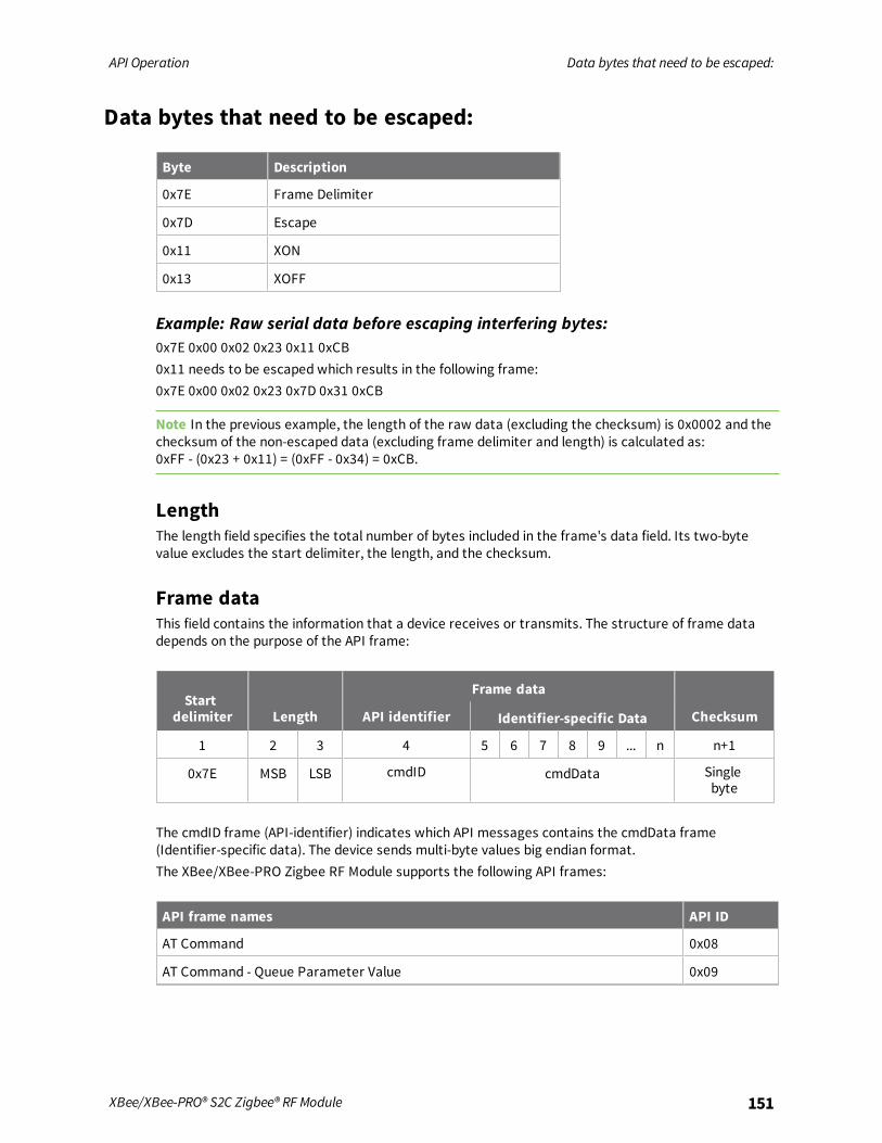
API Operation Data bytes that need to be escaped:
XBee/XBee-PRO® S2C Zigbee® RF Module 151
Data bytes that need to be escaped:
Byte Description
0x7E Frame Delimiter
0x7D Escape
0x11 XON
0x13 XOFF
Example: Raw serial data before escaping interfering bytes:0x7E 0x00 0x02 0x23 0x11 0xCB0x11 needs to be escaped which results in the following frame:0x7E 0x00 0x02 0x23 0x7D 0x31 0xCB
Note In the previous example, the length of the raw data (excluding the checksum) is 0x0002 and thechecksum of the non-escaped data (excluding frame delimiter and length) is calculated as:0xFF - (0x23 + 0x11) = (0xFF - 0x34) = 0xCB.
LengthThe length field specifies the total number of bytes included in the frame's data field. Its two-bytevalue excludes the start delimiter, the length, and the checksum.
Frame dataThis field contains the information that a device receives or transmits. The structure of frame datadepends on the purpose of the API frame:
Startdelimiter Length
Frame data
ChecksumAPI identifier Identifier-specific Data
1 2 3 4 5 6 7 8 9 ... n n+1
0x7E MSB LSB cmdID cmdData Singlebyte
The cmdID frame (API-identifier) indicates which API messages contains the cmdData frame(Identifier-specific data). The device sends multi-byte values big endian format.The XBee/XBee-PRO Zigbee RF Module supports the following API frames:
API frame names API ID
AT Command 0x08
AT Command - Queue Parameter Value 0x09

API Operation Data bytes that need to be escaped:
XBee/XBee-PRO® S2C Zigbee® RF Module 152
API frame names API ID
Zigbee Transmit Request 0x10
Explicit Addressing Zigbee Command Frame 0x11
Remote Command Request 0x17
Create Source Route 0x21
AT Command Response 0x88
Modem Status 0x8A
Zigbee Transmit Status 0x8B
Zigbee Receive Packet (AO=0) 0x90
Zigbee Explicit Rx Indicator (AO=1) 0x91
Zigbee I/O Data Sample Rx Indicator 0x92
XBee Sensor Read Indicator (AO=0) 0x94
Node Identification Indicator (AO=0) 0x95
Remote Command Response 0x97
Extended Modem Status 0x98
Over-the-Air Firmware Update Status 0xA0
Route Record Indicator 0xA1
Many-to-One Route Request Indicator 0xA3
Calculate and verify checksumsTo test data integrity, the device calculates and verifies a checksum on non-escaped data.To calculate the checksum of an API frame:
1. Add all bytes of the packet, except the start delimiter 0x7E and the length (the second andthird bytes).
2. Keep only the lowest 8 bits from the result.
3. Subtract this quantity from 0xFF.
To verify the checksum of an API frame:1. Add all bytes including the checksum; do not include the delimiter and length.
2. If the checksum is correct, the last two digits on the far right of the sum equal 0xFF.
ExampleConsider the following sample data packet: 7E 00 0A 01 01 50 01 00 48 65 6C 6C 6F B8+

API Operation Data bytes that need to be escaped:
XBee/XBee-PRO® S2C Zigbee® RF Module 153
Byte(s) Description
7E Start delimeter
00 0A Length bytes
01 API identifier
01 API frame ID
50 01 Destination address low
00 Option byte
48 65 6C 6C 6F Data packet
B8 Checksum
To calculate the check sum you add all bytes of the packet, excluding the frame delimiter 7E and thelength (the second and third bytes):7E 00 0A 01 01 50 01 00 48 65 6C 6C 6F B8Add these hex bytes:01 + 01 + 50 + 01 + 00 + 48 + 65 + 6C + 6C + 6F = 247If an API data packet is composed with an incorrect checksum, the XBee/XBee-PRO Zigbee RF Modulewill consider the packet invalid and will ignore the data.To verify the check sum of an API packet add all bytes including the checksum (do not include thedelimiter and length) and if correct, the last two far right digits of the sum will equal FF.01 + 01 + 50 + 01 + 00 + 48 + 65 + 6C + 6C + 6F + B8 = 2FF
API examplesExample: Create an API AT command frame to configure a device to allow joining (set NJ to 0xFF).The frame should look like:
0x7E 0x00 0x05 0x08 0x01 0x4E 0x4A 0xFF 5FWhere
n 0x0005 = length
n 0x08 = AT Command API frame type
n 0x01 = Frame ID (set to non-zero value)
n 0x4E4A = AT Command (NJ)
n 0xFF = value to set command to
n 0x5F = Checksum
The checksum is calculated as [0xFF - (0x08 + 0x01 + 0x4E + 0x4A + 0xFF)]Example: Send an ND command to discover the devices in the PAN.The frame should look like:
0x7E 0x00 0x04 0x08 0x01 0x4E 0x44 0x64Where:
n 0x0004 = length
n 0x08 = AT Command API frame type

API Operation API serial exchanges
XBee/XBee-PRO® S2C Zigbee® RF Module 154
n 0x01 = Frame ID (set to non-zero value)
n 0x4E44 = AT command (ND)
n 0x64 = Checksum
The checksum is calculated as [0xFF - (0x08 + 0x01 + 0x4E + 0x44)]Example: Send a remote command to the coordinator to set AD1/DIO1 as a digital input (D1=3) andapply changes to force the I/O update.
The API remote command frame should look like:0x7E 0x00 0x10 0x17 0x01 0x00 0x00 0x00 0x00 0x00 0x00 0x00 0x00 0xFF 0xFE 0x02 0x44 0x31 0x030x70Where:
n 0x10 = length (16 bytes excluding checksum)
n 0x17 = Remote Command API frame type
n 0x01 = Frame ID
n 0x0000000000000000 = Coordinator's address (can be replaced with coordinator's actual 64-bit address if known)
n 0xFFFE = 16- bit Destination Address
n 0x02 = Apply Changes (Remote Command Options)
n 0x4431 = AT command (D1)
n 0x03 = Command Parameter (the parameter could also be sent as 0x0003 or 0x00000003)0x70 = Checksum
API serial exchangesYou can use the Frame ID field to correlate between the outgoing frames and associated responses.
AT commandsThe following image shows the API frame exchange that takes place at the serial interface whensending an AT command request to read or set a device parameter. You can disable the response bysetting the frame ID to 0 in the request.
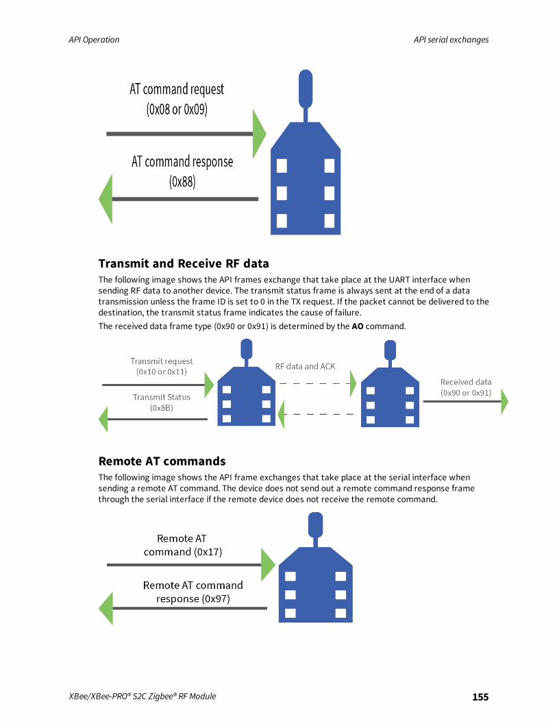
API Operation API serial exchanges
XBee/XBee-PRO® S2C Zigbee® RF Module 155
Transmit and Receive RF dataThe following image shows the API frames exchange that take place at the UART interface whensending RF data to another device. The transmit status frame is always sent at the end of a datatransmission unless the frame ID is set to 0 in the TX request. If the packet cannot be delivered to thedestination, the transmit status frame indicates the cause of failure.The received data frame type (0x90 or 0x91) is determined by the AO command.
Remote AT commandsThe following image shows the API frame exchanges that take place at the serial interface whensending a remote AT command. The device does not send out a remote command response framethrough the serial interface if the remote device does not receive the remote command.

API Operation API serial exchanges
XBee/XBee-PRO® S2C Zigbee® RF Module 156
Source routingThe following image shows the API frame exchanges that take place at the serial port when sending asource routed transmission.
Device RegistrationThe following image shows the API frame exchanges that take place at the serial interface whenregistering a joining device to a trust center.

API Operation Frame descriptions
XBee/XBee-PRO® S2C Zigbee® RF Module 157
Frame descriptionsThe following sections describe the API frames.
AT Command frame - 0x08
DescriptionUse this frame to query or set device parameters on the local device. This API command applieschanges after running the command. You can query parameter values by sending the 0x08 ATCommand frame with no parameter value field (the two-byte AT command is immediately followed bythe frame checksum).
FormatThe following table provides the contents of the frame. For details on frame structure, see API frameformat.
Framedatafields Offset Description
Frametype
3 0x08
ATcommand
5-6 Command name: two ASCII characters that identify the AT command.
Parametervalue
7-n If present, indicates the requested parameter value to set the given register.If no characters are present, it queries the register.
ExampleThe following example illustrates an AT Command frame when you modify the device's NJ parametervalue.
Frame data fields Offset Example
Start delimiter 0 0x7E
Length MSB 1 0x00
LSB 2 0x04
Frame type 3 0x08
Frame ID 4 0x52 (R)
AT command 5 0x4E (N)
6 0x4A (J)
Parameter value (optional)
Checksum 7 0x0D

API Operation Frame descriptions
XBee/XBee-PRO® S2C Zigbee® RF Module 158
AT Command - Queue Parameter Value frame - 0x09
DescriptionThis frame allows you to query or set device parameters. In contrast to the AT Command (0x08)frame, this frame queues new parameter values and does not apply them until you issue either:
n The AT Command (0x08) frame (for API type)
n The AC command
When querying parameter values, the 0x09 frame behaves identically to the 0x08 frame. The devicereturns register queries immediately and not does not queue them. The response for this command isalso an AT Command Response frame (0x88).Send a command to change the baud rate (BD) to 115200 baud, but do not apply changes yet. Themodule continues to operate at the previous baud rate until you apply the changes.
FormatThe following table provides the contents of the frame. For details on frame structure, see API frameformat.
Frame datafields Offset Description
Frame type 3 0x09
Frame ID 4 Identifies the data frame for the host to correlate with a subsequentACK. If set to 0, the device does not send a response.
AT command 5-6 Command name: two ASCII characters that identify the AT command.
Parameter value(BD7 = 115200baud)
7-n If present, indicates the requested parameter value to set the givenregister. If no characters are present, queries the register.
ExampleThe following example sends a command to change the baud rate (BD) to 115200 baud, but does notapply the changes immediately. The device continues to operate at the previous baud rate until youapply the changes.
Note In this example, you could send the parameter as a zero-padded 2-byte or 4-byte value.
Frame data fields Offset Example
Start delimiter 0 0x7E
Length MSB 1 0x00
LSB 2 0x05
Frame type 3 0x09

API Operation Frame descriptions
XBee/XBee-PRO® S2C Zigbee® RF Module 159
Frame data fields Offset Example
Frame ID 4 0x01
AT command 5 0x42 (B)
6 0x44 (D)
Parameter value (BD7 = 115200 baud) 7 0x07
Checksum 8 0x68

API Operation Frame descriptions
XBee/XBee-PRO® S2C Zigbee® RF Module 160
Transmit Request frame - 0x10
DescriptionThis frame causes the device to send payload data as an RF packet to a specific destination.
n For broadcast transmissions, set the 64-bit destination address to 0x000000000000FFFF .Address the coordinator by either setting the 64-bit address to all 0x00s and the 16-bit addressto 0xFFFE, or setting the 64-bit address to the coordinator's 64-bit address and the 16-bitaddress to 0x0000.
n For all other transmissions, setting the 16-bit address to the correct 16-bit address helpsimprove performance when transmitting to multiple destinations. If you do not know a 16-bitaddress, set this field to 0xFFFE (unknown). If successful, the Transmit Status frame (0x8B)indicates the discovered 16-bit address.
You can set the broadcast radius from 0 up to NH. If set to 0, the value of NH specifies the broadcastradius (recommended). This parameter is only used for broadcast transmissions.You can read the maximum number of payload bytes with the NP command.
Note Using source routing reduces the RF payload by two bytes per intermediate hop in the sourceroute.
FormatThe following table provides the contents of the frame. For details on the frame structure, see APIframe format.
Frame datafields Offset Description
Frame type 3 0x10
Frame ID 4 Identifies the data frame for the host to correlate with a subsequentACK. If set to 0, the device does not send a response.
64-bitdestinationaddress
5-12 MSB first, LSB last. Set to the 64-bit address of the destination device.Reserved 64-bit address for the coordinator = 0x0000000000000000Broadcast = 0x000000000000FFFF
16-bitdestinationnetworkaddress
MSB13
LSB14
Set to the 16-bit address of the destination device, if known. If theaddress is unknown or if sending a broadcast, set to 0xFFFE.
Broadcastradius
15 Sets the maximum number of hops a broadcast transmission can occur. Ifset to 0, the broadcast radius is set to the maximum hops value.
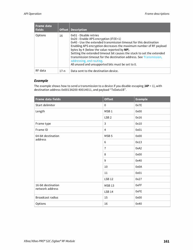
API Operation Frame descriptions
XBee/XBee-PRO® S2C Zigbee® RF Module 161
Frame datafields Offset Description
Options 16 0x01 - Disable retries0x20 - Enable APS encryption (if EE=1)0x40 - Use the extended transmission timeout for this destinationEnabling APS encryption decreases the maximum number of RF payloadbytes by 4 (below the value reported by NP).Setting the extended timeout bit causes the stack to set the extendedtransmission timeout for the destination address. See Transmission,addressing, and routing.All unused and unsupported bits must be set to 0.
RF data 17-n Data sent to the destination device.
ExampleThe example shows how to send a transmission to a device if you disable escaping (AP = 1), withdestination address 0x0013A200 40014011, and payload “TxData1B”.
Frame data fields Offset Example
Start delimiter 0 0x7E
Length MSB 1 0x00
LSB 2 0x16
Frame type 3 0x10
Frame ID 4 0x01
64-bit destinationaddress
MSB 5 0x00
6 0x13
7 0xA2
8 0x00
9 0x40
10 0x0A
11 0x01
LSB 12 0x27
16-bit destinationnetwork address
MSB 13 0xFF
LSB 14 0xFE
Broadcast radius 15 0x00
Options 16 0x40

API Operation Frame descriptions
XBee/XBee-PRO® S2C Zigbee® RF Module 162
Frame data fields Offset Example
RF data 17 0x54
18 0x78
19 0x44
20 0x61
21 0x74
22 0x61
23 0x30
24 0x41
Checksum 25 0x13
Send a transmission to the coordinator without specifying the coordinator's 64-bit address. The APItransmit request frame should look like:
0x7E 0x00 0x16 0x10 0x01 0x00 0x00 0x00 0x00 0x00 0x00 0x00 0x00 0xFF0xFE 0x00 0x00 0x54 0x78 032 0x43 0x6F 0x6F 0x72 0x64 0xFC
Where 0x16 = length (22 bytes excluding checksum)
Frame data fields Offset Example
Start delimiter 0 0x7E
Length MSB 1 0x00
LSB 2 0x16
Frame type 3 0x10
Frame ID 4 0x01
64-bit destinationaddress
MSB 5 0x00
6 0x13
7 0xA2
8 0x00
9 0x40
10 0x0A
11 0x01
LSB 12 0x27
16-bit destinationnetwork address
MSB 13 0xFF
LSB 14 0xFE
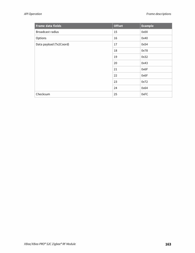
API Operation Frame descriptions
XBee/XBee-PRO® S2C Zigbee® RF Module 163
Frame data fields Offset Example
Broadcast radius 15 0x00
Options 16 0x40
Data payload (Tx2Coord) 17 0x54
18 0x78
19 0x32
20 0x43
21 0x6F
22 0x6F
23 0x72
24 0x64
Checksum 25 0xFC

API Operation Frame descriptions
XBee/XBee-PRO® S2C Zigbee® RF Module 164
Explicit Addressing Command frame - 0x11
DescriptionThis frame is similar to Transmit Request (0x10), but it also requires you to specify the application-layer addressing fields: endpoints, cluster ID, and profile ID.This frame causes the device to send payload data as an RF packet to a specific destination, usingspecific source and destination endpoints, cluster ID, and profile ID.
n For broadcast transmissions, set the 64-bit destination address to 0x000000000000FFFF .Address the coordinator by either setting the 64-bit address to all 0x00s and the 16-bit addressto 0xFFFE, or setting the 64-bit address to the coordinator's 64-bit address and the 16-bitaddress to 0x0000.
n For all other transmissions, setting the 16-bit address to the correct 16-bit address helpsimprove performance when transmitting to multiple destinations. If you do not know a 16-bitaddress, set this field to 0xFFFE (unknown). If successful, the Transmit Status frame (0x8B)indicates the discovered 16-bit address.
You can set the broadcast radius from 0 up to NH to 0xFF. If set to 0, the value of NH specifies thebroadcast radius (recommended). This parameter is only used for broadcast transmissions.You can read the maximum number of payload bytes with the NP command.
Note Using source routing reduces the RF payload by two bytes per intermediate hop in the sourceroute.
FormatThe following table provides the contents of the frame. For details on the frame structure, see APIframe format.
Frame datafields Offset Description
Frame type 3 0x11
Frame ID 4 Identifies the data frame for the host to correlate with a subsequentACK. If set to 0, the device does not send a response.
64-bitdestinationAddress
5-12 MSB first, LSB last. Set to the 64-bit address of the destination device.Reserved 64-bit address for the coordinator = 0x0000000000000000Broadcast = 0x000000000000FFFF
16-bitdestinationNetworkAddress
MSB13
LSB14
Set to the 16-bit address of the destination device, if known. Set to0xFFFE if the address is unknown, or if sending a broadcast.
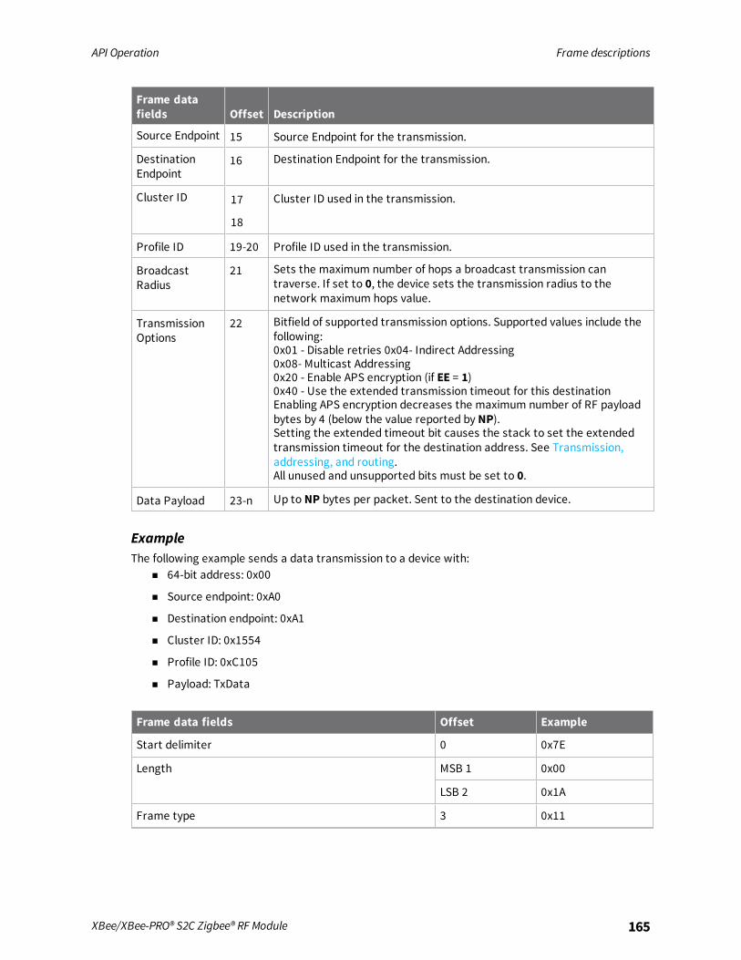
API Operation Frame descriptions
XBee/XBee-PRO® S2C Zigbee® RF Module 165
Frame datafields Offset Description
Source Endpoint 15 Source Endpoint for the transmission.
DestinationEndpoint
16 Destination Endpoint for the transmission.
Cluster ID 17
18
Cluster ID used in the transmission.
Profile ID 19-20 Profile ID used in the transmission.
BroadcastRadius
21 Sets the maximum number of hops a broadcast transmission cantraverse. If set to 0, the device sets the transmission radius to thenetwork maximum hops value.
TransmissionOptions
22 Bitfield of supported transmission options. Supported values include thefollowing:0x01 - Disable retries 0x04- Indirect Addressing0x08- Multicast Addressing0x20 - Enable APS encryption (if EE = 1)0x40 - Use the extended transmission timeout for this destinationEnabling APS encryption decreases the maximum number of RF payloadbytes by 4 (below the value reported by NP).Setting the extended timeout bit causes the stack to set the extendedtransmission timeout for the destination address. See Transmission,addressing, and routing.All unused and unsupported bits must be set to 0.
Data Payload 23-n Up to NP bytes per packet. Sent to the destination device.
ExampleThe following example sends a data transmission to a device with:
n 64-bit address: 0x00
n Source endpoint: 0xA0
n Destination endpoint: 0xA1
n Cluster ID: 0x1554
n Profile ID: 0xC105
n Payload: TxData
Frame data fields Offset Example
Start delimiter 0 0x7E
Length MSB 1 0x00
LSB 2 0x1A
Frame type 3 0x11

API Operation Frame descriptions
XBee/XBee-PRO® S2C Zigbee® RF Module 166
Frame data fields Offset Example
Frame ID 4 0x01
64-bit destination address MSB 5 0x00
6 0x00
7 0x00
8 0x00
9 0x00
10 0x00
11 0x00
LSB12 0x00
16-bit destinationNetwork Address
MSB 13 0xFF
LSB 14 0xFE
Source endpoint 15 0xA0
Destination endpoint 16 0xA1
Cluster ID 17 0x15
18 0x54
Profile ID 19 0xC1
20 0x05
Broadcast radius 21 0x00
Transmit options 22 0x00
Data payload 23 0x54
24 0x78
25 0x44
26 0x61
27 0x74
28 0x61
Checksum 29 0x3A

API Operation Frame descriptions
XBee/XBee-PRO® S2C Zigbee® RF Module 167
Remote AT Command Request frame - 0x17
DescriptionUsed to query or set device parameters on a remote device. For parameter changes on the remotedevice to take effect, you must apply changes, either by setting the Apply Changes options bit, or bysending an AC command to the remote.
FormatThe following table provides the contents of the frame. For details on frame structure, see API frameformat.
Framedatafields Offset Description
Frametype
3 0x17
Frame ID 4 Identifies the data frame for the host to correlate with a subsequent ACK. Ifset to 0, the device does not send a response.
64-bitdestinationaddress
5-12 MSB first, LSB last. Set to the 64-bit address of the destination device.Reserved 64-bit address for the coordinator = 0x0000000000000000
16-bitdestinationaddress
13-14 Set to 0xFFFE if the address is unknown, or if sending a broadcast.
Remotecommandoptions
15 Bitfield to enable various remote command options. Supported values include:
0x01 - Disable ACK
0x40 - Use the extended transmission timeout for this destination. Setting theextended timeout bit causes the stack to set the extended transmissiontimeout for the destination address.For more information, see Transmission, addressing, and routing.
ATcommand
16-17 Command name: two ASCII characters that identify the command.
Commandparameter
18-n If present, indicates the parameter value you request for a given register. Ifno characters are present, it queries the register.
ExampleThe following example sends a remote command:In this example, the 64-bit address of the remote device is 0x0013A200 40401122. The destination 16-bit address is unknown.

API Operation Frame descriptions
XBee/XBee-PRO® S2C Zigbee® RF Module 168
Frame data fields Offset Example
Start delimiter 0 0x7E
Length MSB 1 0x00
LSB 2 0x10
Frame type 3 0x17
Frame ID 4 0x01
64-bit destination address MSB 5 0x00
6 0x13
7 0xA2
8 0x00
9 0x40
10 0x40
11 0x11
LSB 12 0x22
Reserved 13 0xFF
14 0xFE
Remote command options 15 0x02 (apply changes)
AT command 16 0x42 (B)
17 0x48 (H)
Command parameter 18 0x01
Checksum 19 0xF5
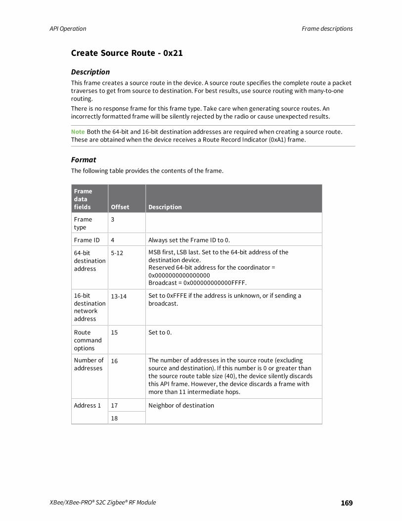
API Operation Frame descriptions
XBee/XBee-PRO® S2C Zigbee® RF Module 169
Create Source Route - 0x21
DescriptionThis frame creates a source route in the device. A source route specifies the complete route a packettraverses to get from source to destination. For best results, use source routing with many-to-onerouting.There is no response frame for this frame type. Take care when generating source routes. Anincorrectly formatted frame will be silently rejected by the radio or cause unexpected results.
Note Both the 64-bit and 16-bit destination addresses are required when creating a source route.These are obtained when the device receives a Route Record Indicator (0xA1) frame.
FormatThe following table provides the contents of the frame.
Framedatafields Offset Description
Frametype
3
Frame ID 4 Always set the Frame ID to 0.
64-bitdestinationaddress
5-12 MSB first, LSB last. Set to the 64-bit address of thedestination device.Reserved 64-bit address for the coordinator =0x0000000000000000Broadcast = 0x000000000000FFFF.
16-bitdestinationnetworkaddress
13-14 Set to 0xFFFE if the address is unknown, or if sending abroadcast.
Routecommandoptions
15 Set to 0.
Number ofaddresses
16 The number of addresses in the source route (excludingsource and destination). If this number is 0 or greater thanthe source route table size (40), the device silently discardsthis API frame. However, the device discards a frame withmore than 11 intermediate hops.
Address 1 17 Neighbor of destination
18

API Operation Frame descriptions
XBee/XBee-PRO® S2C Zigbee® RF Module 170
Framedatafields Offset Description
Address 2(closerhop)
19 Address of intermediate hop
20
Address 3 21 Neighbor of source
22
ExampleYou must order intermediate hop addresses starting with the neighbor of the destination and workingcloser to the source.Suppose a route is found between A and E as shown in the following example.A ' B ' C ' D ' EIf device E has the 64-bit and 16-bit addresses of 0x0013A200 40401122 and 0x3344, and if devices B,C, and D have the following 16-bit addresses:B = 0xAABB C = 0xCCDD D = 0xEEFFThis example shows how to send the Create Source Route frame to establish a source route betweenA and E.
Frame data fields Offset Example
Start delimiter 0 0x7E
Length MSB 1 0x00
LSB 2 0x14
Frame type 3 0x21
Frame ID 4 0x00
64-bit destination address MSB 5 0x00
6 0x13
7 0xA2
8 0x00
9 0x40
10 0x40
11 0x11
LSB 12 0x22
16-bit destinationnetwork address
MSB 13 0x33
LSB 14 0x44
Remote command options 15 0x00

API Operation Frame descriptions
XBee/XBee-PRO® S2C Zigbee® RF Module 171
Frame data fields Offset Example
Number of addresses 16 0x03
Address 1 17 0xEE
18 0xFF
Address 2 (closer hop) 19 0xCC
20 0xDD
Address 3 21 0xAA
22 0xBB
Checksum 23 0x01

API Operation Frame descriptions
XBee/XBee-PRO® S2C Zigbee® RF Module 172
AT Command Response frame - 0x88
DescriptionA device sends this frame in response to an AT Command (0x08 or 0x09) frame. Some commands sendback multiple frames; for example, the ND command.
FormatThe following table provides the contents of the frame. For details on frame structure, see API frameformat.
Frame datafields Offset Description
Frame type 3 0x88
Frame ID 4 Identifies the serial port data frame being reported. If Frame ID = 0 inCommandmode, the device does not give an AT Command Response.
ATcommand
5-6 Command name: two ASCII characters that identify the command.
Commandstatus
7 0 = OK1 = ERROR2 = Invalid command3 = Invalid parameter4 = Tx failure
Commanddata
The register data in binary format. If the host sets the register, the devicedoes not return this field.
ExampleIf you change the BD parameter on a local device with a frame ID of 0x01, and the parameter is valid,the user receives the following response.
Frame datafields Offset Example
Start delimiter 0 0x7E
Length MSB 1 0x00
LSB 2 0x05
Frame type 3 0x88
Frame ID 4 0x01
AT command 5 0x42 (B)
6 0x44 (D)

API Operation Frame descriptions
XBee/XBee-PRO® S2C Zigbee® RF Module 173
Frame datafields Offset Example
Command status 7 0x00
Command data (No command data implies the parameter was set rather thanqueried)
Checksum 8 0xF0

API Operation Frame descriptions
XBee/XBee-PRO® S2C Zigbee® RF Module 174
Modem Status frame - 0x8A
DescriptionDevices send the status messages in this frame in response to specific conditions.
FormatThe following table provides the contents of the frame. For details on frame structure, see API frameformat.
Frame data fields Offset Description
Frame type 3 0x8A
Status 4 0x00 = Hardware reset0x01 = Watchdog timer reset0x02 =Joined network (routers and end devices)0x03 = Disassociated0x06 = Coordinator started0x07 = Network security key was updated0x0D = Voltage supply limit exceeded (PRO only)0x11 = Modem configuration changed while join in progress0x80+ = Ember Zigbee stack error
ExampleWhen a device powers up, it returns the following API frame.
Frame data fields Offset Example
Start delimiter 0 0x7E
Length MSB 1 0x00
LSB 2 LSB 2 0x02
Frame type 3 0x8A
Status 4 0x06
Checksum 5 0x6F

API Operation Frame descriptions
XBee/XBee-PRO® S2C Zigbee® RF Module 175
Transmit Status frame - 0x8B
DescriptionWhen a Transmit Request (0x10, 0x11) completes, the device sends a Transmit Status message out ofthe serial interface. This message indicates if the Transmit Request was successful or if it failed.
Note Broadcast transmissions are not acknowledged and always return a status of 0x00, even if thedelivery failed.
FormatThe following table provides the contents of the frame. For details on frame structure, see API frameformat.
Frame datafields Offset Description
Frame type 3 0x8B
Frame ID 4 Identifies the serial interface data frame being reported. If Frame ID = 0 inthe associated request frame, no response frame is delivered.
16-bitdestinationaddress
5 The 16-bit Network Address where the packet was delivered (ifsuccessful). If not successful, this address is 0xFFFD (destination addressunknown).6
Transmit retrycount
7 The number of application transmission retries that occur.
Deliverystatus
8 0x00 = Success0x01 = MAC ACK Failure0x02 = CCA Failure0x15 = Invalid destination endpoint0x21 = Network ACK Failure0x22 = Not Joined to Network0x23 = Self-addressed0x24 = Address Not Found0x25 = Route Not Found0x26 = Broadcast source failed to hear a neighbor relay the message0x2B = Invalid binding table index0x2C = Resource error lack of free buffers, timers, etc.0x2D = Attempted broadcast with APS transmission0x2E = Attempted unicast with APS transmission, but EE=00x32 = Resource error lack of free buffers, timers, etc.0x74 = Data payload too large0x75 = Indirect message unrequested
Discoverystatus
9 0x00 = No Discovery Overhead0x01 = Address Discovery0x02 = Route Discovery0x03 = Address and Route0x40 = Extended Timeout Discovery
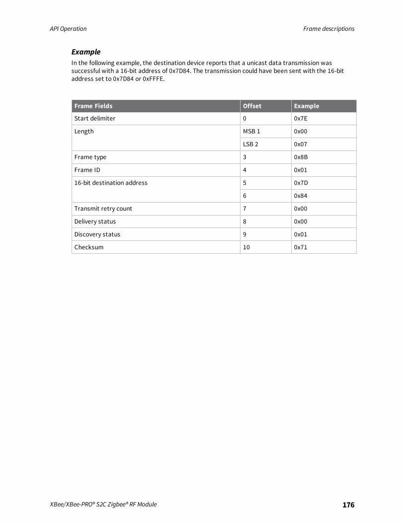
API Operation Frame descriptions
XBee/XBee-PRO® S2C Zigbee® RF Module 176
ExampleIn the following example, the destination device reports that a unicast data transmission wassuccessful with a 16-bit address of 0x7D84. The transmission could have been sent with the 16-bitaddress set to 0x7D84 or 0xFFFE.
Frame Fields Offset Example
Start delimiter 0 0x7E
Length MSB 1 0x00
LSB 2 0x07
Frame type 3 0x8B
Frame ID 4 0x01
16-bit destination address 5 0x7D
6 0x84
Transmit retry count 7 0x00
Delivery status 8 0x00
Discovery status 9 0x01
Checksum 10 0x71
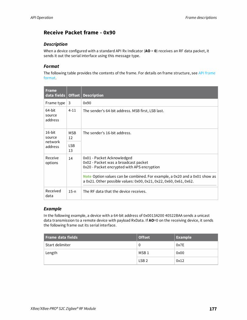
API Operation Frame descriptions
XBee/XBee-PRO® S2C Zigbee® RF Module 177
Receive Packet frame - 0x90
DescriptionWhen a device configured with a standard API Rx Indicator (AO = 0) receives an RF data packet, itsends it out the serial interface using this message type.
FormatThe following table provides the contents of the frame. For details on frame structure, see API frameformat.
Framedata fields Offset Description
Frame type 3 0x90
64-bitsourceaddress
4-11 The sender's 64-bit address. MSB first, LSB last.
16-bitsourcenetworkaddress
MSB12
The sender's 16-bit address.
LSB13
Receiveoptions
14 0x01 - Packet Acknowledged0x02 - Packet was a broadcast packet0x20 - Packet encrypted with APS encryption
Note Option values can be combined. For example, a 0x20 and a 0x01 show asa 0x21. Other possible values: 0x00, 0x21, 0x22, 0x60, 0x61, 0x62.
Receiveddata
15-n The RF data that the device receives.
ExampleIn the following example, a device with a 64-bit address of 0x0013A200 40522BAA sends a unicastdata transmission to a remote device with payload RxData. If AO=0 on the receiving device, it sendsthe following frame out its serial interface.
Frame data fields Offset Example
Start delimiter 0 0x7E
Length MSB 1 0x00
LSB 2 0x12

API Operation Frame descriptions
XBee/XBee-PRO® S2C Zigbee® RF Module 178
Frame data fields Offset Example
Frame type 3 0x90
64-bit source address MSB 4 0x00
5 0x13
6 0xA2
7 0x00
8 0x40
9 0x52
10 0x2B
LSB 11 0xAA
16-bit source network address MSB 12 0x7D
LSB 13 0x84
Receive options 14 0x01
Received data 15 0x52
16 0x78
17 0x44
18 0x61
19 0x74
20 0x61
Checksum 21 0x0D
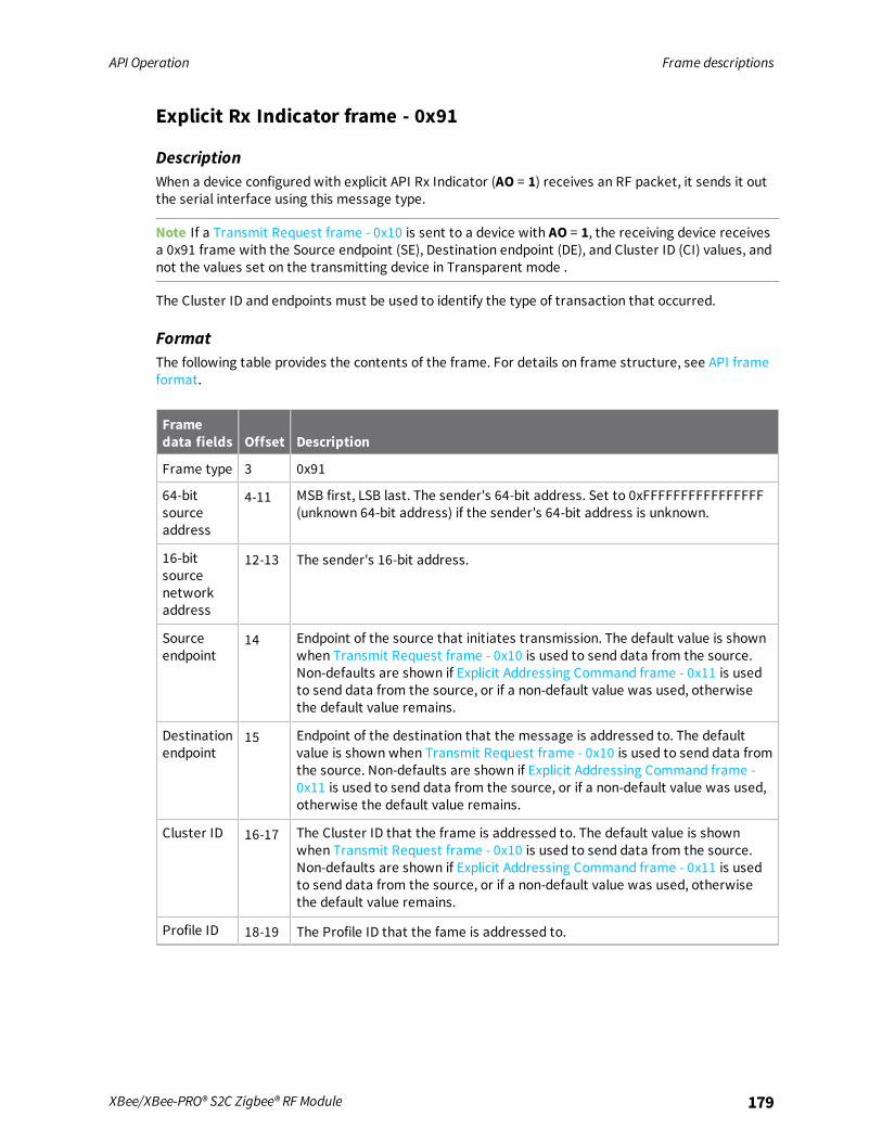
API Operation Frame descriptions
XBee/XBee-PRO® S2C Zigbee® RF Module 179
Explicit Rx Indicator frame - 0x91
DescriptionWhen a device configured with explicit API Rx Indicator (AO = 1) receives an RF packet, it sends it outthe serial interface using this message type.
Note If a Transmit Request frame - 0x10 is sent to a device with AO = 1, the receiving device receivesa 0x91 frame with the Source endpoint (SE), Destination endpoint (DE), and Cluster ID (CI) values, andnot the values set on the transmitting device in Transparent mode .
The Cluster ID and endpoints must be used to identify the type of transaction that occurred.
FormatThe following table provides the contents of the frame. For details on frame structure, see API frameformat.
Framedata fields Offset Description
Frame type 3 0x91
64-bitsourceaddress
4-11 MSB first, LSB last. The sender's 64-bit address. Set to 0xFFFFFFFFFFFFFFFF(unknown 64-bit address) if the sender's 64-bit address is unknown.
16-bitsourcenetworkaddress
12-13 The sender's 16-bit address.
Sourceendpoint
14 Endpoint of the source that initiates transmission. The default value is shownwhen Transmit Request frame - 0x10 is used to send data from the source.Non-defaults are shown if Explicit Addressing Command frame - 0x11 is usedto send data from the source, or if a non-default value was used, otherwisethe default value remains.
Destinationendpoint
15 Endpoint of the destination that the message is addressed to. The defaultvalue is shown when Transmit Request frame - 0x10 is used to send data fromthe source. Non-defaults are shown if Explicit Addressing Command frame -0x11 is used to send data from the source, or if a non-default value was used,otherwise the default value remains.
Cluster ID 16-17 The Cluster ID that the frame is addressed to. The default value is shownwhen Transmit Request frame - 0x10 is used to send data from the source.Non-defaults are shown if Explicit Addressing Command frame - 0x11 is usedto send data from the source, or if a non-default value was used, otherwisethe default value remains.
Profile ID 18-19 The Profile ID that the fame is addressed to.
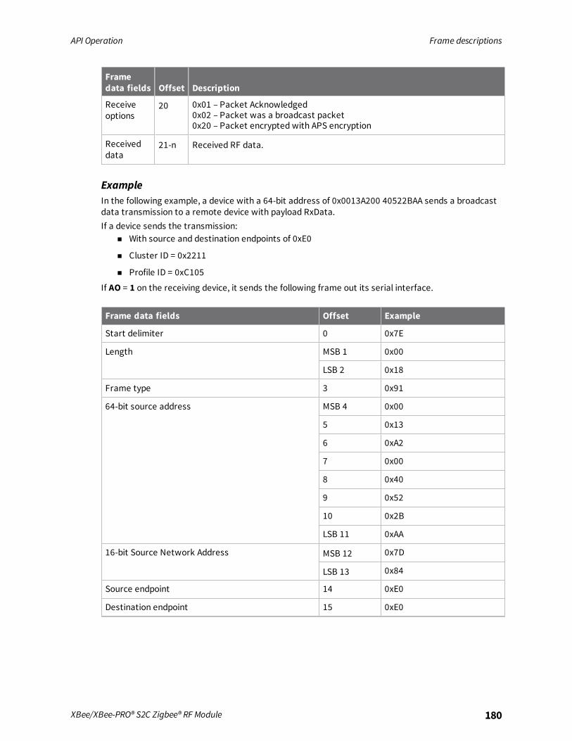
API Operation Frame descriptions
XBee/XBee-PRO® S2C Zigbee® RF Module 180
Framedata fields Offset Description
Receiveoptions
20 0x01 – Packet Acknowledged0x02 – Packet was a broadcast packet0x20 – Packet encrypted with APS encryption
Receiveddata
21-n Received RF data.
ExampleIn the following example, a device with a 64-bit address of 0x0013A200 40522BAA sends a broadcastdata transmission to a remote device with payload RxData.If a device sends the transmission:
n With source and destination endpoints of 0xE0
n Cluster ID = 0x2211
n Profile ID = 0xC105
If AO = 1 on the receiving device, it sends the following frame out its serial interface.
Frame data fields Offset Example
Start delimiter 0 0x7E
Length MSB 1 0x00
LSB 2 0x18
Frame type 3 0x91
64-bit source address MSB 4 0x00
5 0x13
6 0xA2
7 0x00
8 0x40
9 0x52
10 0x2B
LSB 11 0xAA
16-bit Source Network Address MSB 12 0x7D
LSB 13 0x84
Source endpoint 14 0xE0
Destination endpoint 15 0xE0

API Operation Frame descriptions
XBee/XBee-PRO® S2C Zigbee® RF Module 181
Frame data fields Offset Example
Cluster ID 16 0x22
17 0x11
Profile ID 18 0xC1
19 0x05
Receive options 20 0x02 (Broadcast)
Received data 21 0x52
22 0x78
23 0x44
24 0x61
25 0x74
26 0x61
Checksum 27 0x52
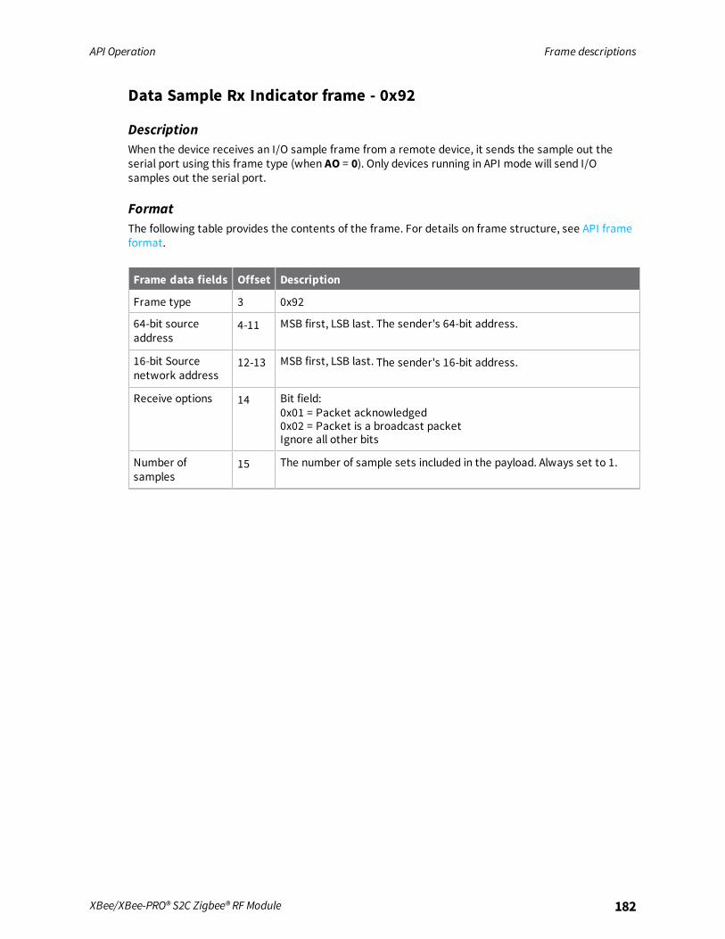
API Operation Frame descriptions
XBee/XBee-PRO® S2C Zigbee® RF Module 182
Data Sample Rx Indicator frame - 0x92
DescriptionWhen the device receives an I/O sample frame from a remote device, it sends the sample out theserial port using this frame type (when AO = 0). Only devices running in API mode will send I/Osamples out the serial port.
FormatThe following table provides the contents of the frame. For details on frame structure, see API frameformat.
Frame data fields Offset Description
Frame type 3 0x92
64-bit sourceaddress
4-11 MSB first, LSB last. The sender's 64-bit address.
16-bit Sourcenetwork address
12-13 MSB first, LSB last. The sender's 16-bit address.
Receive options 14 Bit field:0x01 = Packet acknowledged0x02 = Packet is a broadcast packetIgnore all other bits
Number ofsamples
15 The number of sample sets included in the payload. Always set to 1.

API Operation Frame descriptions
XBee/XBee-PRO® S2C Zigbee® RF Module 183
Frame data fields Offset Description
Digital channelmask 1
16-17 Bitmask field that indicates which digital I/O lines on the remote havesampling enabled, if any.bit 0 = DIO0bit 1 = DIO1bit 2 = DIO2bit 3 = DIO3bit 4 = DIO4bit 5 = DIO5bit 6 = DIO6bit 7 = DIO7bit 8 = DIO8bit 9 = DIO9bit 10 = DIO10bit 11 = DIO11bit 12 = DIO12bit 13 = DIO13bit 14 = DIO14bit 15 = N/AFor example, a digital channel mask of 0x002F means DIOs 0, 1, 2, 3,and 5 are enabled as digital I/O.
Analog channelmask 2
18 Bitmask field that indicates which analog I/O lines on the remote havesampling enabled, if any.bit 0 = AD0/DIO0bit 1 = AD1/DIO1bit 2 = AD2/DIO2bit 3 = AD3/DIO3bit 7 = Supply Voltage (enabled with V+ command)
Digital samples (ifincluded)
19-20 If the sample set includes any digital I/O lines (Digital channel mask >0), these two bytes contain samples for all enabled digital I/O lines.DIO lines that do not have sampling enabled return 0. Bits in these twobytes map the same as they do in the Digital channel mask field.
Analog sample 21-22 If the sample set includes any analog I/O lines (Analog channel mask >0), each enabled analog input returns a 2-byte value indicating the A/Dmeasurement of that input. Analog samples are ordered sequentiallyfrom ADO/DIO0 to AD3/DIO3.
ExampleIn the following example, the device receives an I/O sample with an analog and digital I/O from aremove device with a 64-bit serial number of 0x0013A20040522BAA and a 16-bit address of 0x7D84.If you enable pin AD1/DIO1 as an analog input, enable AD2/DIO2 and DIO4 as digital inputs (currentlyhigh), and enable AD3/DIO3 as a digital output (low) the I/O sample is shown in the API example in thefollowing table.
1N/A N/A N/A CD/DIC12 PWM/DI011 RSSI/DIO10 N/A N/ACTS/DI07 RTS/DI06 ASSOC/DI05 DI04 AD3/DI03 AD2/DI02 AD1/DIO1 AD0/DIO0CTS/DI07 RTS/DI06 ASSOC/DI05 DI04 AD3/DI03 AD2/DI02 AD1/DIO1 AD0/DIO02Supply Voltage N/A N/A N/A AD3 AD2 AD1 AD0

API Operation Frame descriptions
XBee/XBee-PRO® S2C Zigbee® RF Module 184
Frame fields Offset Example
Start delimiter 0 0x7E
Length MSB 1 0x00
LSB 2 0x14
Frame type 3 0x92
64-bit source address MSB 4 0x00
5 0x13
6 0xA2
7 0x00
8 0x40
9 0x52
10 0x2B
LSB 11 0xAA
16-bit source network address MSB 12 0x7D
LSB 13 0x84
Receive options 14 0x01
Number of samples 15 0x01
Digital channel mask 16 0x00
17 0x1C
Analog channel mask 18 0x02
Digital samples (if included) 19 0x00
20 0x14
Analog sample 21 0x02
22 0x25
Checksum 23 0xF5

API Operation Frame descriptions
XBee/XBee-PRO® S2C Zigbee® RF Module 185
XBee Sensor Read Indicator - 0x94
DescriptionWhen the device receives a sensor sample (from a Digi 1-wire sensor adapter), it is sent out the serialport using this message type (when AO=0).
FormatThe following table provides the contents of the frame. For details on frame structure, see API frameformat.
Frame data fields Offset Description
Frame type 3 0x94
64-bit sourceaddress
4-11 MSB first, LSB last. The sender's 64-bit address.
16-bit Sourcenetwork address
12-13 MSB first, LSB last. The sender's 16-bit address.
Receive options 14 0x01 = Packet acknowledged0x02 = Packet is a broadcast packet
1-Wire Sensors 15 0x01 = A/D Sensor Read0x02 = Temperature Sensor Read0x60 = Water present (module CD pin low)
A/D Values 16 Indicates a two-byte value for each of four A/D sensors (A, B, C, D).Set to 0xFFFFFFFFFFFFFFFF if no A/Ds are found.
17
18
19
20
21
22
23
Temperature Read 24 Indicates the two-byte value read from a digital thermometer ifpresent. Set to 0xFFFF if not found.
25
ExampleSuppose a device receives a 1-wire sensor sample from a device with a 64-bit address of 0x0013A20040522BAA and a 16-bit address of 0xDD6C. If the sensor sample comes from a 1-wire humidity sensor,the API frame could look like this (if AO=0):For convenience, let's label the A/D and temperature readings as AD0, AD1, AD2, AD3, and T. Using thedata in this example:
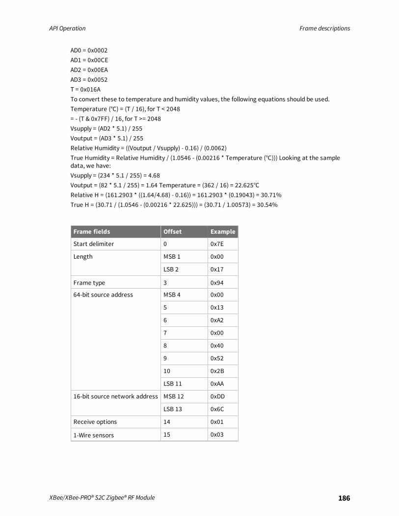
API Operation Frame descriptions
XBee/XBee-PRO® S2C Zigbee® RF Module 186
AD0 = 0x0002AD1 = 0x00CEAD2 = 0x00EAAD3 = 0x0052T = 0x016ATo convert these to temperature and humidity values, the following equations should be used.Temperature (°C) = (T / 16), for T < 2048= - (T & 0x7FF) / 16, for T >= 2048Vsupply = (AD2 * 5.1) / 255Voutput = (AD3 * 5.1) / 255Relative Humidity = ((Voutput / Vsupply) - 0.16) / (0.0062)True Humidity = Relative Humidity / (1.0546 - (0.00216 * Temperature (°C))) Looking at the sampledata, we have:Vsupply = (234 * 5.1 / 255) = 4.68Voutput = (82 * 5.1 / 255) = 1.64 Temperature = (362 / 16) = 22.625°CRelative H = (161.2903 * ((1.64/4.68) - 0.16)) = 161.2903 * (0.19043) = 30.71%True H = (30.71 / (1.0546 - (0.00216 * 22.625))) = (30.71 / 1.00573) = 30.54%
Frame fields Offset Example
Start delimiter 0 0x7E
Length MSB 1 0x00
LSB 2 0x17
Frame type 3 0x94
64-bit source address MSB 4 0x00
5 0x13
6 0xA2
7 0x00
8 0x40
9 0x52
10 0x2B
LSB 11 0xAA
16-bit source network address MSB 12 0xDD
LSB 13 0x6C
Receive options 14 0x01
1-Wire sensors 15 0x03

API Operation Frame descriptions
XBee/XBee-PRO® S2C Zigbee® RF Module 187
Frame fields Offset Example
A/D Values 16 0x00
17 0x02
18 0x00
19 0xCE
20 0x00
21 0xEA
22 0x00
23 0x52
Temperature Read 24 0x01
25 0x6A
Checksum 26 0x8B

API Operation Frame descriptions
XBee/XBee-PRO® S2C Zigbee® RF Module 188
Node Identification Indicator frame - 0x95
DescriptionA device receives this frame when:
n it transmits a node identification message to identify itself
n AO = 0
FormatThe following table provides the contents of the frame. For details on frame structure, see API frameformat.
Frame datafields Offset Description
Frame type 3 0x95
64-bit sourceaddress
4-11 MSB first, LSB last. The sender's 64-bit address.
16-bit sourcenetworkaddress
12-13 MSB first, LSB last. The sender's 16-bit address.
Receive options 14 0x01 = Packet acknowledged0x02 = Packet was a broadcast packet
Source 16-bitaddress
15-16 Set to the 16-bit network address of the remote device. Set to 0xFFFE ifunknown.
64-bit networkaddress
17-24 Indicates the 64-bit address of the remote device that transmitted theNode Identification Indicator frame.
NI string 25-26 Node identifier string on the remote device. The NI string is terminatedwith a NULL byte (0x00).
Device type 29 0 = Coordinator1 = Router2 = End Device
Source event 30 1 = Frame sent by node identification pushbutton event (see D0(AD0/DIO0 Configuration))2 = Frame sent after joining event occurred (see JN (Join Notification)).3 = Frame sent after power cycle event occurred (see JN (JoinNotification)).
Digi Profile ID 31-32 Set to Digi’s application profile ID.
DigiManufacturerID
33-34 Set to Digi’s Manufacturer ID.

API Operation Frame descriptions
XBee/XBee-PRO® S2C Zigbee® RF Module 189
ExampleIf you press the commissioning pushbutton on a remote device with 64-bit address0x0013A200407402AC and a default NI string sends a Node Identification, all devices on the networkreceive the following node identification indicator:A remote device with 64-bit address 0x0013A200407402AC and a default NI string sends a NodeIdentification, all devices on the network receive the following node identification indicator:If you press the commissioning button on a remote router device with 64-bit address 0x0013A20040522BAA, 16-bit address 0x7D84, and default NI string, devices on the network receive the nodeidentification indicator.
Frame data fields Offset Example
Start delimiter 0 0x7E
Length MSB 1 0x00
LSB 2 0x20
Frame type 3 0x95
64-bit source address MSB 4 0x00
5 0x13
6 0xA2
7 0x00
8 0x40
9 0x52
10 0x2B
LSB 11 0xAA
16-bit sourcenetwork address
MSB 12 0x7D
LSB 13 0x84
Receive options 14 0x02
Source 16-bit address 15 0x7D
16 0x84

API Operation Frame descriptions
XBee/XBee-PRO® S2C Zigbee® RF Module 190
Frame data fields Offset Example
64-bit network address 17 0x00
18 0x13
19 0xA2
20 0x00
21 0x40
22 0x52
23 0x2B
24 0xAA
NI string 25 0x20
26 0x00
Parent 16-bit address 27 0xFF
28 0xFE
Device type 29 0x01
Source event 30 0x01
Digi Profile ID 31 0xC1
32 0x05
Digi Manufacturer ID 33 0x10
34 0x1E
Checksum 35 0x1B

API Operation Frame descriptions
XBee/XBee-PRO® S2C Zigbee® RF Module 191
Remote Command Response frame - 0x97
DescriptionIf a device receives this frame in response to a Remote Command Request (0x17) frame, the devicesends an AT Command Response (0x97) frame out the serial interface.Some commands, such as the ND command, may send back multiple frames.
FormatThe following table provides the contents of the frame. For details on frame structure, see API frameformat.
Frame data fields Offset Description
Frame type 3 0x97
Frame ID 4 This is the same value that is passed in to the request.
64-bit source(remote) address
5-12 The address of the remote device returning this response.
16-bit source (remote) address
13-14 Set to the 16-bit network address of the remote device returningthis response. Set to 0xFFFE if unknown.
AT commands 15-16 The name of the command.
Command status 17 0 = OK1 = ERROR2 = Invalid Command3 = Invalid Parameter4 = Remote Command Transmission Failed
Command data 18-n The register data in binary format. If you set the register, the devicedoes not return this field.
ExampleIf a device sends a remote command to a remote device with 64-bit address 0x0013A200 40522BAA toquery the SL command, and if the frame ID = 0x55, the response would look like the followingexample.
Frame data fields Offset Example
Start delimiter 0 0x7E
Length MSB 1 0x00
LSB 2 0x13
Frame type 3 0x97
Frame ID 4 0x55

API Operation Frame descriptions
XBee/XBee-PRO® S2C Zigbee® RF Module 192
Frame data fields Offset Example
64-bit source (remote) address MSB 5 0x00
6 0x13
7 0xA2
8 0x00
9 0x40
10 0x52
11 0x2B
LSB 12 0xAA
16-bit source (remote) address MSB 13 0x7D
LSB 14 0x84
AT commands 15 0x53
16 0x4C
Command status 17 0x00
Command data 18 0x40
19 0x52
20 0x2B
21 0xAA
Checksum 22 0xF4

API Operation Frame descriptions
XBee/XBee-PRO® S2C Zigbee® RF Module 193
Extended Modem Status frame - 0x98
DescriptionIf you enable the Verbose Join option (DC10), the device serially transmits trace messages to describewhat is happening inside the device during association.
WARNING! This option is provided for diagnostic purposes. With 4x5A/7x5A or later,Verbose Join messages are disabled while the device is operating in Commandmode.Prior to that revision, Verbose Join messages are interspersed with serialcommunications.
FormatThe following table provides the contents of the frame. For details on frame structure, see API frameformat.
Frame data fields Offset Description
Frame type 3 0x98
Status code 4 See the following table for status code descriptions.
Status data 5 The length of this field varies with the Status Code.
Example
Frame data fields Offset Example
Start delimiter 0 0x7E
Length MSB 1 0x00
LSB 2 0x03
Checksum 6 0x5C
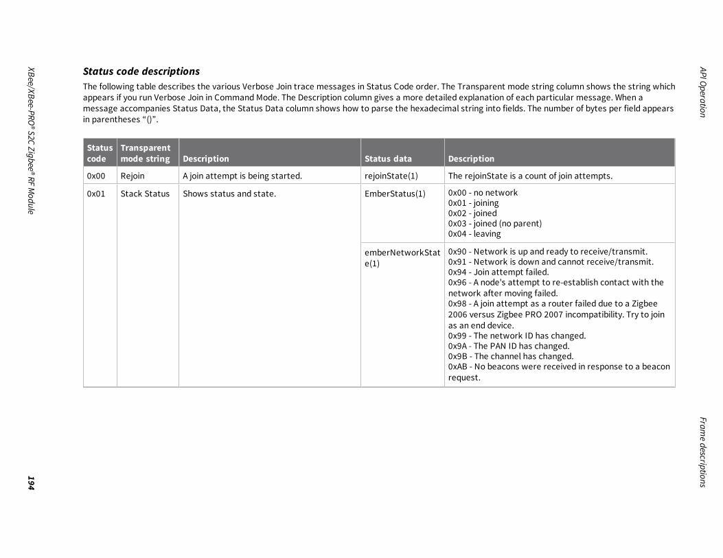
APIOperationFram
edescriptions
XBee/XBee-PRO®S2CZigbee®RF
Module
194
Status code descriptionsThe following table describes the various Verbose Join trace messages in Status Code order. The Transparent mode string column shows the string whichappears if you run Verbose Join in Command Mode. The Description column gives a more detailed explanation of each particular message. When amessage accompanies Status Data, the Status Data column shows how to parse the hexadecimal string into fields. The number of bytes per field appearsin parentheses “()”.
Statuscode
Transparentmode string Description Status data Description
0x00 Rejoin A join attempt is being started. rejoinState(1) The rejoinState is a count of join attempts.
0x01 Stack Status Shows status and state. EmberStatus(1) 0x00 - no network0x01 - joining0x02 - joined0x03 - joined (no parent)0x04 - leaving
emberNetworkState(1)
0x90 - Network is up and ready to receive/transmit.0x91 - Network is down and cannot receive/transmit.0x94 - Join attempt failed.0x96 - A node's attempt to re-establish contact with thenetwork after moving failed.0x98 - A join attempt as a router failed due to a Zigbee2006 versus Zigbee PRO 2007 incompatibility. Try to joinas an end device.0x99 - The network ID has changed.0x9A - The PAN ID has changed.0x9B - The channel has changed.0xAB - No beacons were received in response to a beaconrequest.
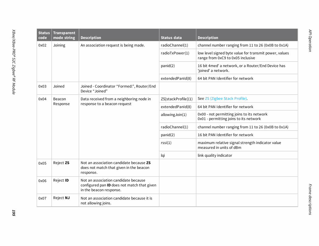
APIOperationFram
edescriptions
XBee/XBee-PRO®S2CZigbee®RF
Module
195
Statuscode
Transparentmode string Description Status data Description
0x02 Joining An association request is being made. radioChannel(1) channel number ranging from 11 to 26 (0x0B to 0x1A)
radioTxPower(1) low level signed byte value for transmit power, valuesrange from 0xC9 to 0x05 inclusive
panid(2) 16 bit 4med' a network, or a Router/End Device has'joined' a network.
extendedPanId(8) 64 bit PAN Identifier for network
0x03 Joined Joined - Coordinator “Formed:”, Router/EndDevice “Joined”
0x04 BeaconResponse
Data received from a neighboring node inresponse to a beacon request
ZS[stackProfile](1) See ZS (Zigbee Stack Profile).
extendedPanId(8) 64 bit PAN Identifier for network
allowingJoin(1) 0x00 - not permitting joins to its network0x01 - permitting joins to its network
radioChannel(1) channel number ranging from 11 to 26 (0x0B to 0x1A)
panid(2) 16 bit PAN Identifier for network
rssi(1) maximum relative signal strength indicator valuemeasured in units of dBm
lqi link quality indicator
0x05 Reject ZS Not an association candidate because ZSdoes not match that given in the beaconresponse.
0x06 Reject ID Not an association candidate becauseconfigured pan ID does not match that givenin the beacon response.
0x07 Reject NJ Not an association candidate because it isnot allowing joins.

APIOperationFram
edescriptions
XBee/XBee-PRO®S2CZigbee®RF
Module
196
Statuscode
Transparentmode string Description Status data Description
0x08 panID Match JV/NW with search option (DO80) has founda matching network.
panId(2) 16 bit PAN Identifier for network
0x09 RejectLQIRSSI
JV/NW with search option (DO80) candidaterejected because this beacon response isweaker than an earlier beacon response.
0x0A Beacon Saved This beacon response is a suitable candidatefor an association request.
radioChannel(1) channel number ranging from 11 to 26 (0x0B to 0x1A)
radioTxPower(1) low level signed byte value for transmit power, valuesrange from 0xC9 to 0x05 inclusive
panid(2) 16 bit PAN Identifier for network
extendedPanId(8) 64 bit PAN Identifier for network
0x0B AI AI value has changed. AIStatusCode(1) See a description of AI command
0x0C Permit Join NJ setting (Permit Join Duration) haschanged
value(1) See a description of the NJ (Node Join Time) command.
0x0D Scanning Active scanning has begun. ChannelMask(4) A 32 bit value driven by the SC setting where bit positions11 through 26 show which channels are enabled for theupcoming Active Scan. See a description of SC (ScanChannels).
0x0E Scan Error An error occurred during active scan. StatusCode(1)
0x0F Join Request High level request for a form/join.
0x10 Reject LQI Reject because LQI is worse than an alreadysaved beacon
lqi(1) link quality indicator
0x11 Reject RSSI Rejected because RSSI is worse than analready saved beacon
rssi(1) relative signal strength indicator

APIOperationFram
edescriptions
XBee/XBee-PRO®S2CZigbee®RF
Module
197
Statuscode
Transparentmode string Description Status data Description
0x12 Rejected(cmdL ast)
Rejected because it matches the lastassociated network.
0x13 Rejected(cmdS ave)
Rejected because it matches an alreadysaved beacon response.
0x14 Rejectstrength
During first/best phase, response is weakerthan an already saved beacon response.
0x16 Reset forDC80
With DC80 enabled, reset if no joinablebeacon responses are received within 60s ofjoining.
0x18 ScanCh Scanning on Channel radioChannel(1) channel number ranging from 11 to 26 (0x0B to 0x1A)
0x19 Scan Mode Shows phase of Ordered Association. mode(1) 0: first/bestcandidate1: ordered association by extpanid, then by channel
0x1A Scan Init Starting a scan channel(1)TxPower(1)
channel being scannedlow level radio transmit power setting
0x1D Energy Scan -channel mask
Starting energy scan SC mask(4) Scan channel mask
0x1E Energy Scan -energies
Channel Energies observed Energies(16) Energy Levels per channel in SC
0x1F PanIdScan -radio channel
Pan Id Scan starting on channel channel(1) Radio Channel
0x20 FormNetwork- parameters
Forming a network radioChannel(1) channel number ranging form 11 to 26
radioTxPower(1) low level radio transmit power setting
panid(2) 16 bit PAN identifier for network
extendedpanid(8) 64 bit PAN identifier for network

APIOperationFram
edescriptions
XBee/XBee-PRO®S2CZigbee®RF
Module
198
Statuscode
Transparentmode string Description Status data Description
0x21 DiscoveringKE Endpoint
Looking for Key Establishment Endpoint
0x22 KE Endpoint Found Key Establishment Endpoint Endpoint(1) Endpoint number
The following example shows a successful association with Verbose Join enabled in AT Command Mode.
Note Comments are included with the trace messages to explain the content and are preceded by an ellipsis “...”.
+++OKatid3151 OK
...configured pan identifier has been changed atdc10
OK
...and verbose join enabled atac
OK
...applying changes to the configuration V AI - Searching for Parent:FF
...search has started
V AI - Searching for Parent:FF
...and started again
V Scanning:03FFF800
...Channels 11 through 25 are enabled by the SC setting for the Active Search.
V Beacon Rsp:0000000000000042A6010B949AC8FF
...ZS(0), extendedPanId(00000000000042A6), allowingJoin(1), radiochannel(0x0B), panid(949A), rssi(C8), lqi(FF)
V Reject ID
...beacon response's extendedPanId does not match this radio's ID setting of 3151

APIOperationFram
edescriptions
XBee/XBee-PRO®S2CZigbee®RF
Module
199
V Beacon Rsp:0200000000000002AB010C55D2B2DB
...ZS(2), extendedPanId(00000000000002AB), allowingJoin(1), radiochannel(0x0C), panid(55D2), rssi(B2), lqi(DB)V Reject ZS
...beacon response's ZS does not match this radio's ZS setting of 0x00
V Beacon Rsp:000000000000003151010EE29FDFFFV Beacon Saved:0E05E29F0000000000003151
...this beacon response is acceptable as a candidate for association
V Joining:0E05E29F0000000000003151
...sending association request
V Stack Status: joined, network up 0290
...we are joined, the network is up, we can send and transmit
V Joined:V AI - Association Succeeded:00
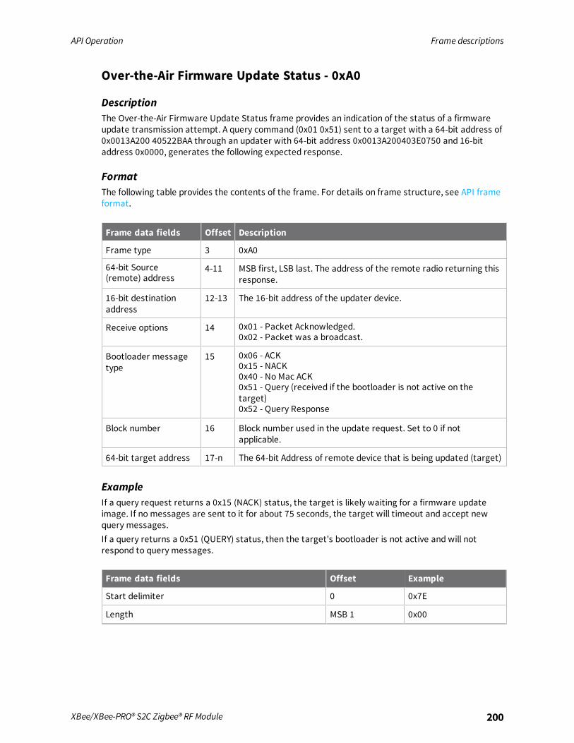
API Operation Frame descriptions
XBee/XBee-PRO® S2C Zigbee® RF Module 200
Over-the-Air Firmware Update Status - 0xA0
DescriptionThe Over-the-Air Firmware Update Status frame provides an indication of the status of a firmwareupdate transmission attempt. A query command (0x01 0x51) sent to a target with a 64-bit address of0x0013A200 40522BAA through an updater with 64-bit address 0x0013A200403E0750 and 16-bitaddress 0x0000, generates the following expected response.
FormatThe following table provides the contents of the frame. For details on frame structure, see API frameformat.
Frame data fields Offset Description
Frame type 3 0xA0
64-bit Source(remote) address
4-11 MSB first, LSB last. The address of the remote radio returning thisresponse.
16-bit destinationaddress
12-13 The 16-bit address of the updater device.
Receive options 14 0x01 - Packet Acknowledged.0x02 - Packet was a broadcast.
Bootloader messagetype
15 0x06 - ACK0x15 - NACK0x40 - No Mac ACK0x51 - Query (received if the bootloader is not active on thetarget)0x52 - Query Response
Block number 16 Block number used in the update request. Set to 0 if notapplicable.
64-bit target address 17-n The 64-bit Address of remote device that is being updated (target)
ExampleIf a query request returns a 0x15 (NACK) status, the target is likely waiting for a firmware updateimage. If no messages are sent to it for about 75 seconds, the target will timeout and accept newquery messages.If a query returns a 0x51 (QUERY) status, then the target's bootloader is not active and will notrespond to query messages.
Frame data fields Offset Example
Start delimiter 0 0x7E
Length MSB 1 0x00

API Operation Frame descriptions
XBee/XBee-PRO® S2C Zigbee® RF Module 201
Frame data fields Offset Example
LSB 2 0x16
Frame type 3 0xA0
64-bit source (remote) address MSB 4 0x00
5 0x13
6 0xA2
7 0x00
8 0x40
9 0x3E
10 0x07
11 0x50
16-bit destination address 12 0x00
13 0x00
Receive options 14 0x01
Bootloader message type 15 0x52
Block number 16 0x00
64-bit target address 17 0x00
18 0x13
19 0xA2
20 0x00
21 0x40
22 0x52
23 0x2B
24 0xAA
Checksum 25 0x66
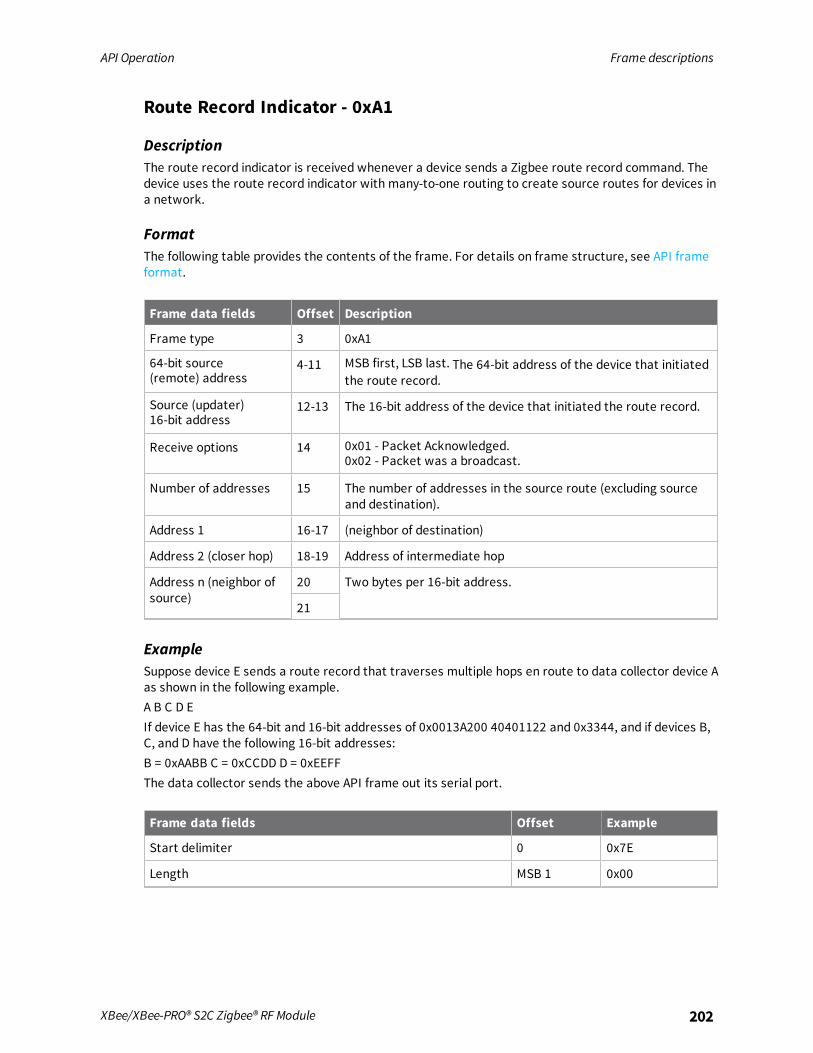
API Operation Frame descriptions
XBee/XBee-PRO® S2C Zigbee® RF Module 202
Route Record Indicator - 0xA1
DescriptionThe route record indicator is received whenever a device sends a Zigbee route record command. Thedevice uses the route record indicator with many-to-one routing to create source routes for devices ina network.
FormatThe following table provides the contents of the frame. For details on frame structure, see API frameformat.
Frame data fields Offset Description
Frame type 3 0xA1
64-bit source(remote) address
4-11 MSB first, LSB last. The 64-bit address of the device that initiatedthe route record.
Source (updater)16-bit address
12-13 The 16-bit address of the device that initiated the route record.
Receive options 14 0x01 - Packet Acknowledged.0x02 - Packet was a broadcast.
Number of addresses 15 The number of addresses in the source route (excluding sourceand destination).
Address 1 16-17 (neighbor of destination)
Address 2 (closer hop) 18-19 Address of intermediate hop
Address n (neighbor ofsource)
20 Two bytes per 16-bit address.
21
ExampleSuppose device E sends a route record that traverses multiple hops en route to data collector device Aas shown in the following example.A B C D EIf device E has the 64-bit and 16-bit addresses of 0x0013A200 40401122 and 0x3344, and if devices B,C, and D have the following 16-bit addresses:B = 0xAABB C = 0xCCDD D = 0xEEFFThe data collector sends the above API frame out its serial port.
Frame data fields Offset Example
Start delimiter 0 0x7E
Length MSB 1 0x00

API Operation Frame descriptions
XBee/XBee-PRO® S2C Zigbee® RF Module 203
Frame data fields Offset Example
LSB 2 0x13
Frame type 3 0xA1
64-bit source (remote) address MSB 4 0x00
5 0x13
6 0xA2
7 0x00
8 0x40
9 0x40
10 0x11
11 0x22
Source (updater) 16-bit address 12 0x33
13 0x44
Receive options 14 0x01
Number of Addresses 15 0x03
Address 1 16 0xEE
17 0xFF
Address 2 (closer hop) 18 0xCC
19 0xDD
Address n (neighbor of source) 20 0xAA
21 0xBB
Checksum 22 0x80
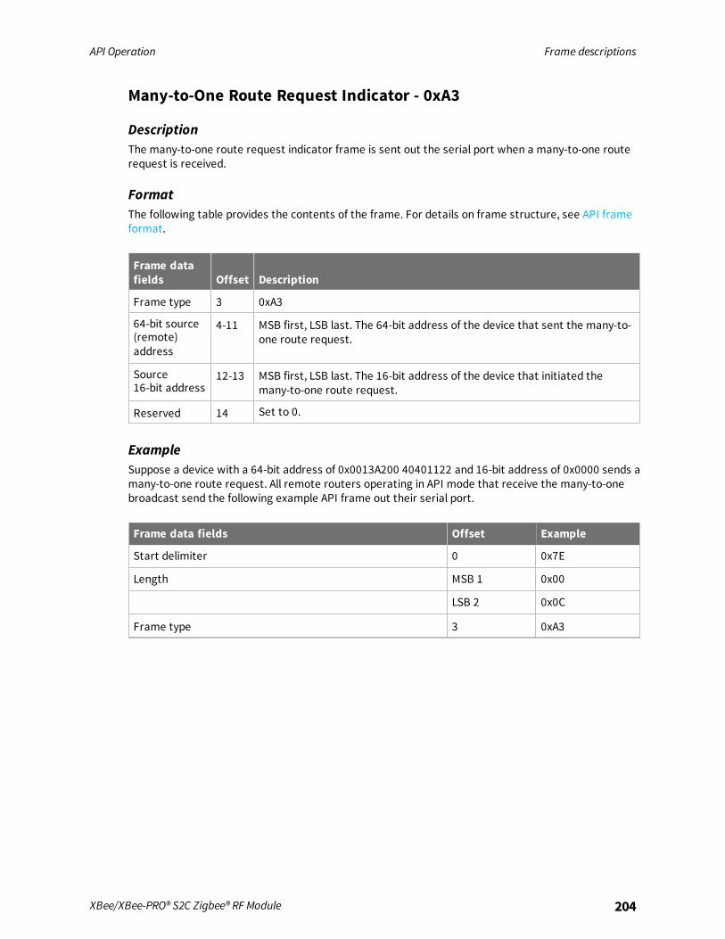
API Operation Frame descriptions
XBee/XBee-PRO® S2C Zigbee® RF Module 204
Many-to-One Route Request Indicator - 0xA3
DescriptionThe many-to-one route request indicator frame is sent out the serial port when a many-to-one routerequest is received.
FormatThe following table provides the contents of the frame. For details on frame structure, see API frameformat.
Frame datafields Offset Description
Frame type 3 0xA3
64-bit source(remote)address
4-11 MSB first, LSB last. The 64-bit address of the device that sent the many-to-one route request.
Source16-bit address
12-13 MSB first, LSB last. The 16-bit address of the device that initiated themany-to-one route request.
Reserved 14 Set to 0.
ExampleSuppose a device with a 64-bit address of 0x0013A200 40401122 and 16-bit address of 0x0000 sends amany-to-one route request. All remote routers operating in API mode that receive the many-to-onebroadcast send the following example API frame out their serial port.
Frame data fields Offset Example
Start delimiter 0 0x7E
Length MSB 1 0x00
LSB 2 0x0C
Frame type 3 0xA3
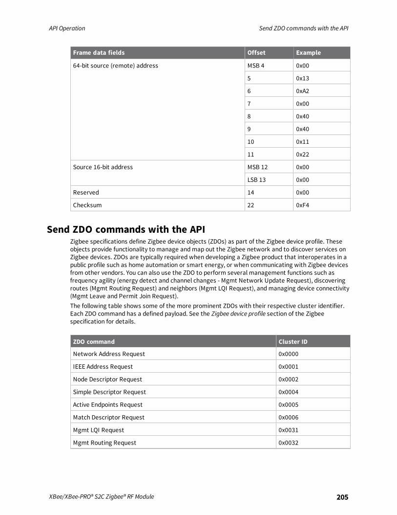
API Operation Send ZDO commands with the API
XBee/XBee-PRO® S2C Zigbee® RF Module 205
Frame data fields Offset Example
64-bit source (remote) address MSB 4 0x00
5 0x13
6 0xA2
7 0x00
8 0x40
9 0x40
10 0x11
11 0x22
Source 16-bit address MSB 12 0x00
LSB 13 0x00
Reserved 14 0x00
Checksum 22 0xF4
Send ZDO commands with the APIZigbee specifications define Zigbee device objects (ZDOs) as part of the Zigbee device profile. Theseobjects provide functionality to manage andmap out the Zigbee network and to discover services onZigbee devices. ZDOs are typically required when developing a Zigbee product that interoperates in apublic profile such as home automation or smart energy, or when communicating with Zigbee devicesfrom other vendors. You can also use the ZDO to perform several management functions such asfrequency agility (energy detect and channel changes - Mgmt Network Update Request), discoveringroutes (Mgmt Routing Request) and neighbors (Mgmt LQI Request), andmanaging device connectivity(Mgmt Leave and Permit Join Request).The following table shows some of the more prominent ZDOs with their respective cluster identifier.Each ZDO command has a defined payload. See the Zigbee device profile section of the Zigbeespecification for details.
ZDO command Cluster ID
Network Address Request 0x0000
IEEE Address Request 0x0001
Node Descriptor Request 0x0002
Simple Descriptor Request 0x0004
Active Endpoints Request 0x0005
Match Descriptor Request 0x0006
Mgmt LQI Request 0x0031
Mgmt Routing Request 0x0032

API Operation Send ZDO commands with the API
XBee/XBee-PRO® S2C Zigbee® RF Module 206
ZDO command Cluster ID
Mgmt Leave Request 0x0034
Mgmt Permit Joining Request 0x0036
Mgmt Network Update Request 0x0038
Use the Explicit Addressing Command frame - 0x11 to send Zigbee device objects commands todevices in the network. Sending ZDO commands with the Explicit Transmit API frame requires someformatting of the data payload field.When sending a ZDO command with the API, all multiple byte values in the ZDO command (APIpayload), for example, u16, u32, and 64-bit addresses, must be sent in little endian byte order for thecommand to be executed correctly on a remote device.For an API XBee to receive ZDO responses, set AO command to 1 to enable the explicit receive APIframe.The following table shows how you can use the Explicit API frame to send an “Active Endpoints”request to discover the active endpoints on a device with a 16-bit address of 0x1234.
Frame data fields Offset Description
Frame type 3 0x11
Frame ID 4 Identifies the data frame for the host to correlate with asubsequent transmit status. If set to 0, the device does not send aresponse out the serial port.
64-bit destinationaddress
5-12 MSB first, LSB last. The 64-bit address of the destination device (bigendian byte order). For unicast transmissions, set to the 64-bitaddress of the destination device, or to 0x0000000000000000 tosend a unicast to the coordinator. Set to 0x000000000000FFFF forbroadcast.
16-bit destinationnetwork address
13 MSB first, LSB last. The 16-bit address of the destination device (bigendian byte order). Set to 0xFFFE for broadcast, or if the 16-bitaddress is unknown.14
Source endpoint 15 Set to 0x00 for ZDO transmissions (endpoint 0 is the ZDOendpoint).
Destination endpoint 16 Set to 0x00 for ZDO transmissions (endpoint 0 is the ZDOendpoint).
Cluster ID 17 Set to the cluster ID that corresponds to the ZDO command beingsent.0x0005 = Active Endpoints Request18
Profile ID 19-20 Set to 0x0000 for ZDO transmissions (Profile ID 0x0000 is theZigbee device profile that supports ZDOs).
Broadcast radius 21 Sets the maximum number of hops a broadcast transmission cantraverse. If set to 0, the device sets the transmission radius to thenetwork maximum hops value.

API Operation Send ZDO commands with the API
XBee/XBee-PRO® S2C Zigbee® RF Module 207
Frame data fields Offset Description
Transmission options 22 All bits must be set to 0.
Data payload 23 The required payload for a ZDO command. All multi-byte ZDOparameter values (u16, u32, 64- bit address) must be sent in littleendian byte order.The Active Endpoints Request includes the following payload:[16-bit NwkAddrOfInterest]
Note The 16-bit address in the API example (0x1234) is sent in littleendian byte order (0x3412).
24
25
ExampleThe following example shows how you can use the Explicit API frame to send an “Active Endpoints”request to discover the active endpoints on a device with a 16-bit address of 0x1234.
Frame data fields Offset Example
Start delimiter 0 0x7E
Length MSB 1 0x00
LSB 2 0x17
Frame type 3 0x11
Frame ID 4 0x01
64-bit destination address MSB 5 0x00
6 0x00
7 0x00
8 0x00
9 0x00
10 0x00
11 0xFF
LSB12 0xFF
16-bit DestinationNetwork Address
MSB 13 0xFF
LSB 14 0xFE
Source endpoint 15 0x00
Destination endpoint 16 0x00
Cluster ID 17 0x00
18 0x05

API Operation Send Zigbee cluster library (ZCL) commands with the API
XBee/XBee-PRO® S2C Zigbee® RF Module 208
Frame data fields Offset Example
Profile ID 19 0x00
20 0x00
Broadcast radius 21 0x00
Transmit options 22 0x00
Data payload - transaction sequence number 23 0x01
Data payload - ZDO payload 24 0x34
25 0x12
Checksum 29 0xA6
Send Zigbee cluster library (ZCL) commands with the APIThe Zigbee cluster library defines a set of attributes and commands (clusters) that can be supportedin multiple Zigbee profiles. The ZCL commands are typically required when developing a Zigbeeproduct that will interoperate in a public profile such as home automation or smart energy, or whencommunicating with Zigbee devices from other vendors. Applications that are not designed for apublic profile or for interoperability applications can skip this section.The following table shows some prominent clusters with their respective attributes and commands.
Cluster (Cluster ID) Attributes (Attribute ID) Cluster ID
Basic (0x0000) Application Version (0x0001)Hardware Version (0x0003)Model Identifier (0x0005)
Reset to defaults (0x00)
Identify (0x0003) Identify Time (0x0000) Identify (0x00)Identify Query (0x01)
Time (0x000A) Time (0x0000)Time Status (0x0001)Time Zone (0x0002)
Thermostat (0x0201) Local Temperature (0x0000)Occupancy (0x0002)
Setpoint raise / lower (0x00)
The ZCL defines a number of profile-wide commands that can be supported on any profile, also knownas general commands. These commands include the following.
Command (Command ID) Description
Read Attributes (0x00) Used to read one or more attributes on a remote device.
Read Attributes Response(0x01)
Generated in response to a read attributes command.
Write Attributes (0x02) Used to change one or more attributes on a remote device.

API Operation Send Zigbee cluster library (ZCL) commands with the API
XBee/XBee-PRO® S2C Zigbee® RF Module 209
Command (Command ID) Description
Write Attributes Response(0x04)
Sent in response to a write attributes command.
Configure Reporting(0x06)
Used to configure a device to automatically report on the values of oneor more of its attributes.
Report Attributes (0x0A) Used to report attributes when report conditions have been satisfied.
Discover Attributes (0x0C) Used to discover the attribute identifiers on a remote device.
Discover AttributesResponse (0x0D)
Sent in response to a discover attributes command.
Use the Explicit Addressing Command frame - 0x11 to send ZCL commands to devices in the network.Sending ZCL commands with the Explicit Transmit API frame requires some formatting of the datapayload field.When sending a ZCL command with the API, all multiple byte values in the ZCL command (API Payload)(for example, u16, u32, 64-bit addresses) must be sent in little endian byte order for the command tobe executed correctly on a remote device.
Note When sending ZCL commands, set the AO command to 1 to enable the explicit receive API frame.This provides indication of the source 64- and 16-bit addresses, cluster ID, profile ID, and endpointinformation for each received packet. This information is required to properly decode received data.
The following table shows how the Explicit API frame can be used to read the hardware versionattribute from a device with a 64-bit address of 0x0013A200 40401234 (unknown 16-bit address). Thisexample uses arbitrary source and destination endpoints. The hardware version attribute (attributeID 0x0003) is part of the basic cluster (cluster ID 0x0000). The Read Attribute general command ID is0x00.
Frame fields Offset Description
Frame type 3
Frame ID 4 Identifies the serial port data frame for the host tocorrelate with a subsequent transmit status. If set to0, no transmit status frame will be sent out the serialport.

API Operation Send Zigbee cluster library (ZCL) commands with the API
XBee/XBee-PRO® S2C Zigbee® RF Module 210
Frame fields Offset Description
64-bitdestinationaddress
MSB 5 The 64-bit address of the destination device (bigendian byte order). For unicast transmissions, set tothe 64-bit address of the destination device, or to0x0000000000000000 to send a unicast to thecoordinator. Set to 0x000000000000FFFF forbroadcast.
6
7
8
9
10
11
LSB12
16-bitdestinationnetworkaddress
MSB13
The 16-bit address of the destination device (bigendian byte order). Set to 0xFFFE for broadcast, or ifthe 16-bit address is unknown.
LSB14
Sourceendpoint
15 Set to the source endpoint on the sending device(0x41 arbitrarily selected).
Destinationendpoint
16 Set to the destination endpoint on the remote device(0x42 arbitrarily selected).
Cluster ID MSB17
Set to the cluster ID that corresponds to the ZCLcommand being sent. 0x0000 = Basic Cluster.
LSB18
Profile ID MSB19
Set to the profile ID supported on the device (0xD123arbitrarily selected).
LSB20
Broadcastradius
21 Sets the maximum number of hops a broadcasttransmission can traverse. If set to 0, thetransmission radius will be set to the networkmaximum hops value.
Transmitoptions
22 All bits must be set to 0.
Datapayload
ZCLframeheader
Framecontrol
23 Bitfield that defines the command type and otherrelevant information in the ZCL command. For moreinformation, see the ZCL specification.

API Operation Send Zigbee cluster library (ZCL) commands with the API
XBee/XBee-PRO® S2C Zigbee® RF Module 211
Frame fields Offset Description
Transactionsequencenumber
24 A sequence number used to correlate a ZCL commandwith a ZCL response. (The hardware version responsewill include this byte as a sequence number in theresponse.) The value 0x01 was arbitrarily selected.
CommandID
25 Since the frame control “frame type” bits are 00, thisbyte specifies a general command. Command ID 0x00is a Read Attributes command.
ZCLpayload
Attribute ID 26 The payload for a “Read Attributes” command is a listof Attribute Identifiers that are being read.
Note The 16-bit Attribute ID (0x0003) is sent in littleendian byte order (0x0300). All multi- byte ZCL headerand payload values must be sent in little endian byteorder.
27 0xFF minus the 8 bit sum of bytes from offset 3 to thisbyte.
ExampleIn this example, the Frame Control field (offset 23) is constructed as follows:
Name Bits Example Value Description
Frame Type 0-1 00 - Command acts across the entire profile.
Manufacturer Specific 2 0 - The manufacturer code field is omitted from the ZCL FrameHeader.
Direction 3 0 - The command is being sent from the client side to the serverside.
Disable DefaultResponse
4 0 - Default response not disabled.
Reserved 5-7 Set to 0.
For more information, see the Zigbee Cluster Library specification.
Frame data fields Offset Example
Start delimiter 0 0x7E
Length MSB 1 0x00
LSB 2 0x19
Frame type 3 0x11
Frame ID 4 0x01
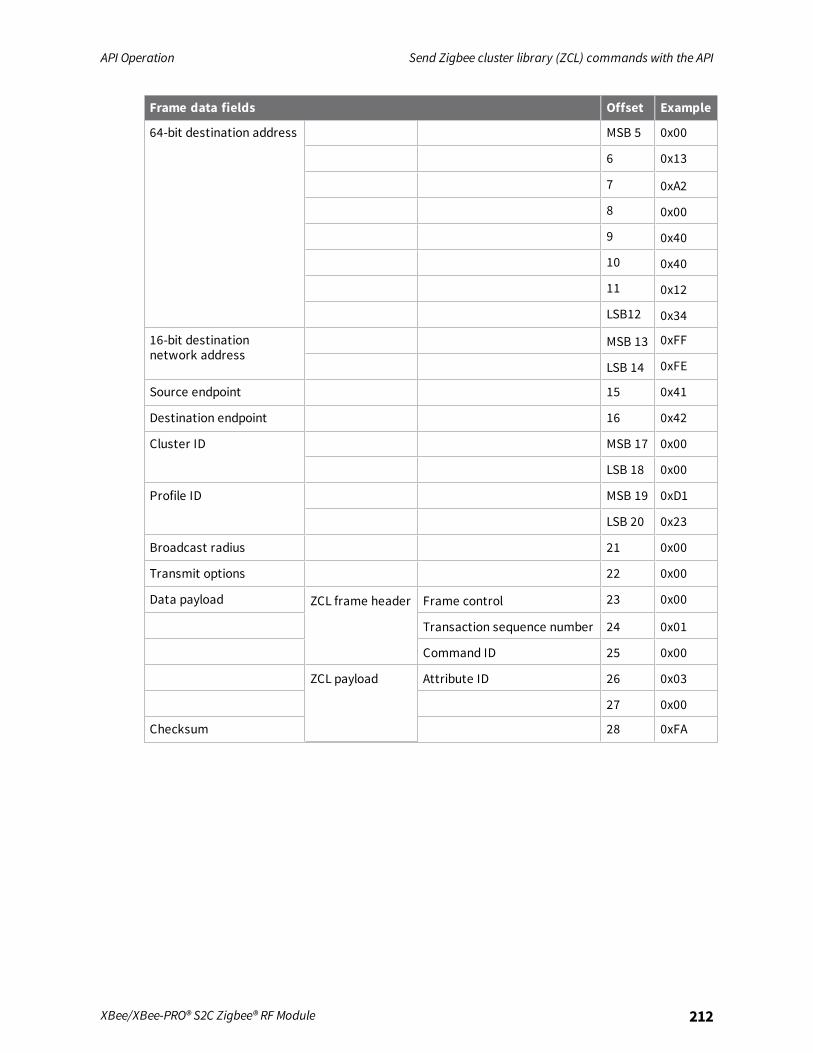
API Operation Send Zigbee cluster library (ZCL) commands with the API
XBee/XBee-PRO® S2C Zigbee® RF Module 212
Frame data fields Offset Example
64-bit destination address MSB 5 0x00
6 0x13
7 0xA2
8 0x00
9 0x40
10 0x40
11 0x12
LSB12 0x34
16-bit destinationnetwork address
MSB 13 0xFF
LSB 14 0xFE
Source endpoint 15 0x41
Destination endpoint 16 0x42
Cluster ID MSB 17 0x00
LSB 18 0x00
Profile ID MSB 19 0xD1
LSB 20 0x23
Broadcast radius 21 0x00
Transmit options 22 0x00
Data payload ZCL frame header Frame control 23 0x00
Transaction sequence number 24 0x01
Command ID 25 0x00
ZCL payload Attribute ID 26 0x03
27 0x00
Checksum 28 0xFA

API Operation Send Public Profile Commands with the API
XBee/XBee-PRO® S2C Zigbee® RF Module 213
Send Public Profile Commands with the APIYou can use the XBee API using the Explicit Transmit API frame (0x11) to send commands in publicprofiles such as Smart Energy and Home Automation. Sending public profile commands with theExplicit Transmit API frame requires some formatting of the data payload field. Most of the publicprofile commands fit into the Zigbee cluster library (ZCL) architecture as described in Send Zigbeecluster library (ZCL) commands with the API.The following table shows how you can use the Explicit API frame to send a demand response and loadcontrol message (cluster ID 0x701) in the smart energy profile (profile ID 0x0109) in the revision 14Smart Energy specification. The device sends a “Load Control Event”message (command ID 0x00) andto a device with 64- bit address of 0x0013A200 40401234 with a 16-bit address of 0x5678. The eventstarts a load control event for water heaters and smart appliances for a duration of 1 minute, startingimmediately.
Note When sending public profile commands, set the AO command to 1 to enable the explicit receiveAPI frame. This provides indication of the source 64- and 16-bit addresses, cluster ID, profile ID, andendpoint information for each received packet. This information is required to properly decodereceived data.
Frame specific data
Frame Fields Offset Description
Frame type 3
Frame ID 4 Identifies the serial port data frame for the host tocorrelate with a subsequent transmit status. If setto 0, no transmit status frame will be sent out theserial port.
64-bitdestinationaddress
MSB 5 The 64-bit address of the destination device (bigendian byte order). For unicast transmissions, set tothe 64-bit address of the destination device, or to0x0000000000000000 to send a unicast to thecoordinator. Set to 0x000000000000FFFF forbroadcast.
6
7
8
9
10
11
LSB12
16-bitdestinationnetworkaddress
MSB13
The 16-bit address of the destination device (bigendian byte order). Set to 0xFFFE for broadcast, or ifthe 16-bit address is unknown.
LSB14
Sourceendpoint
15 Set to the source endpoint on the sending device.(0x41 arbitrarily selected).

API Operation Send Public Profile Commands with the API
XBee/XBee-PRO® S2C Zigbee® RF Module 214
Frame Fields Offset Description
Destinationendpoint
16 Set to the destination endpoint on the remotedevice. (0x42 arbitrarily selected).
Cluster ID MSB17
Set to the cluster ID that corresponds to the ZCLcommand being sent. 0x0701 = Demand responseand load control cluster ID
LSB18
Profile ID MSB19
Set to the profile ID supported on the device. 0x0109= Smart Energy profile ID.
LSB20
Broadcastradius
21 Sets the maximum number of hops a broadcasttransmission can traverse. If set to 0, thetransmission radius will be set to the networkmaximum hops value.
Transmitoptions
22 All bits must be set to 0.
Datapayload
ZCLframeheader
Framecontrol
23 Bitfield that defines the command type and otherrelevant information in the ZCL command. For moreinformation, see the ZCL specification.
Transactionsequencenumber
24 A sequence number used to correlate a ZCLcommand with a ZCL response. (The hardwareversion response will include this byte as a sequencenumber in the response.) The value 0x01 wasarbitrarily selected.
25 Since the frame control “frame type” bits are 01, thisbyte specifies a cluster-specific command. CommandID 0x00 in the Demand Response and Load Controlcluster is a Load Control Event command. For moreinformation, see the Smart Energy specification.
ZCLpayload- loadcontroleventdata
Issuer eventID
26 The 4-byte unique identifier.
Note The 4-byte ID is sent in little endian byte order(0x78563412).
The event ID in this example (0x12345678) isarbitrarily selected.
27
28
29

API Operation Send Public Profile Commands with the API
XBee/XBee-PRO® S2C Zigbee® RF Module 215
Frame Fields Offset Description
Device class 30 This bit encoded field represents the Device Classassociated with the Load Control Event. A bit value of0x0014 enables smart appliances and water heaters.
Note The 2-byte bit field value is sent in little endianbyte order.
31
Utilityenrollmentgroup
32 Used to identify sub-groups of devices in the device-class. 0x00 addresses all groups.
Start time 33
34
35
36
Duration inminutes
37 This 2-byte value must be sent in little endian byteorder.
38
Criticalitylevel
39 Indicates the criticality level of the event. In thisexample, the level is “voluntary”.
Coolingtemperature
40 Requested offset to apply to the normal cooling setpoint.A value of 0xFF indicates the temperature offsetvalue is not used.
Heatingtemperatureoffset
41 Requested offset to apply to the normal heating setpoint.A value of 0xFF indicates the temperature offsetvalue is not used.
Coolingtemperatureset point
42 Requested cooling set point in 0.01 degrees Celsius.A value of 0x8000 means the set point field is notused in this event.
Note The 0x80000 is sent in little endian byte order.43
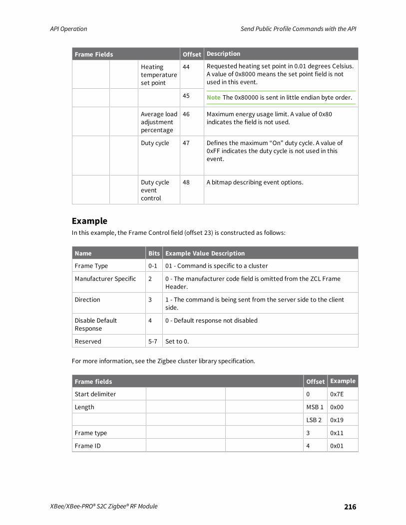
API Operation Send Public Profile Commands with the API
XBee/XBee-PRO® S2C Zigbee® RF Module 216
Frame Fields Offset Description
Heatingtemperatureset point
44 Requested heating set point in 0.01 degrees Celsius.A value of 0x8000 means the set point field is notused in this event.
Note The 0x80000 is sent in little endian byte order.45
Average loadadjustmentpercentage
46 Maximum energy usage limit. A value of 0x80indicates the field is not used.
Duty cycle 47 Defines the maximum “On” duty cycle. A value of0xFF indicates the duty cycle is not used in thisevent.
Duty cycleeventcontrol
48 A bitmap describing event options.
ExampleIn this example, the Frame Control field (offset 23) is constructed as follows:
Name Bits Example Value Description
Frame Type 0-1 01 - Command is specific to a cluster
Manufacturer Specific 2 0 - The manufacturer code field is omitted from the ZCL FrameHeader.
Direction 3 1 - The command is being sent from the server side to the clientside.
Disable DefaultResponse
4 0 - Default response not disabled
Reserved 5-7 Set to 0.
For more information, see the Zigbee cluster library specification.
Frame fields Offset Example
Start delimiter 0 0x7E
Length MSB 1 0x00
LSB 2 0x19
Frame type 3 0x11
Frame ID 4 0x01
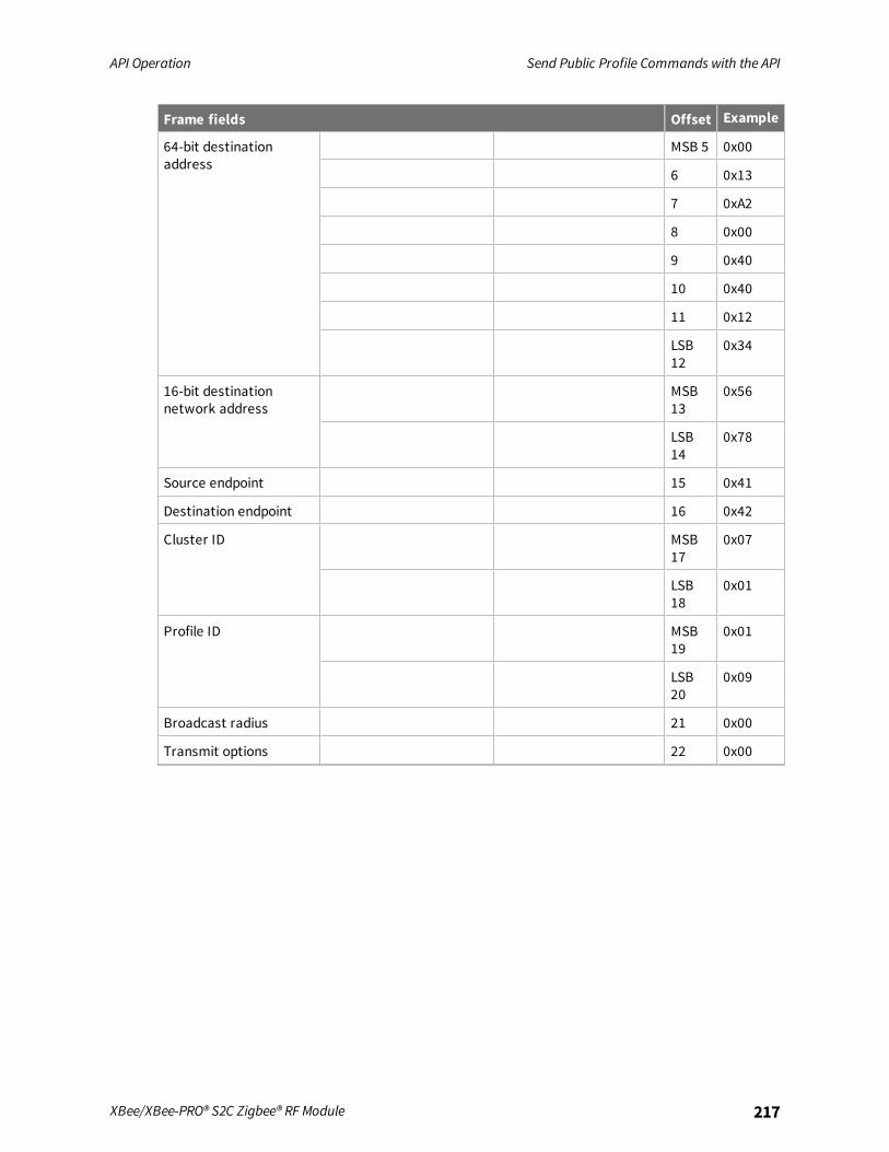
API Operation Send Public Profile Commands with the API
XBee/XBee-PRO® S2C Zigbee® RF Module 217
Frame fields Offset Example
64-bit destinationaddress
MSB 5 0x00
6 0x13
7 0xA2
8 0x00
9 0x40
10 0x40
11 0x12
LSB12
0x34
16-bit destinationnetwork address
MSB13
0x56
LSB14
0x78
Source endpoint 15 0x41
Destination endpoint 16 0x42
Cluster ID MSB17
0x07
LSB18
0x01
Profile ID MSB19
0x01
LSB20
0x09
Broadcast radius 21 0x00
Transmit options 22 0x00

API Operation Send Public Profile Commands with the API
XBee/XBee-PRO® S2C Zigbee® RF Module 218
Frame fields Offset Example
Data payload ZCL frame header Frame control 23 0x09
Transaction sequencenumber
24 0x01
25 0x00
ZCL payload - load controlevent data
Issuer event ID 26 0x78
27 0x56
28 0x34
29 0x12
Device class 30 0x14
31 0x00
Utility enrollment group 32 0x00
Start time 33 0x00
34 0x00
35 0x00
36 0x00
Duration in Minutes 37 0x01
38 0x00
Criticality level 39 0x04
Cooling temperature 40 0xFF
Heating temperatureoffset
41 0xFF
Cooling temperature setpoint
42 0x00
43 0x80
Heating temperature setpoint
44 0x00
45 0x80
Average load adjustmentpercentage
46 0x80
Duty cycle 47 0xFF
Duty cycle event control 48 0x00
Checksum 49 0x5B

AT commands
Addressing commands 220Network commands 224Security commands 231RF interfacing commands 232Serial interfacing commands 234I/O settings commands 237Diagnostic commands 249Commandmode options 251Sleep commands 252Execution commands 255
XBee/XBee-PRO® S2C Zigbee® RF Module 219
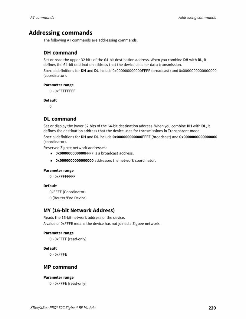
AT commands Addressing commands
XBee/XBee-PRO® S2C Zigbee® RF Module 220
Addressing commandsThe following AT commands are addressing commands.
DH commandSet or read the upper 32 bits of the 64-bit destination address. When you combine DH with DL, itdefines the 64-bit destination address that the device uses for data transmission.Special definitions for DH and DL include 0x000000000000FFFF (broadcast) and 0x0000000000000000(coordinator).
Parameter range0 - 0xFFFFFFFF
Default0
DL commandSet or display the lower 32 bits of the 64-bit destination address. When you combine DH with DL, itdefines the destination address that the device uses for transmissions in Transparent mode.Special definitions for DH and DL include 0x000000000000FFFF (broadcast) and 0x0000000000000000(coordinator).Reserved Zigbee network addresses:
n 0x000000000000FFFF is a broadcast address.
n 0x0000000000000000 addresses the network coordinator.
Parameter range0 - 0xFFFFFFFF
Default0xFFFF (Coordinator)0 (Router/End Device)
MY (16-bit Network Address)Reads the 16-bit network address of the device.A value of 0xFFFE means the device has not joined a Zigbee network.
Parameter range0 - 0xFFFF [read-only]
Default0 - 0xFFFE
MP command
Parameter range0 - 0xFFFE [read-only]

AT commands Addressing commands
XBee/XBee-PRO® S2C Zigbee® RF Module 221
Default0xFFFE
NC commandRead the number of remaining end device children that can join the device. If NC returns 0, the deviceis at capacity and cannot allow any more end device children to join.
Parameter range0 - MAX_CHILDREN (maximum varies) [read-only]
DefaultN/A
SH commandDisplays the upper 32 bits of the unique IEEE 64-bit extended address assigned to the XBee in thefactory.
The 64-bit source address is always enabled. This value is read-only and it never changes.
Parameter range0 - 0xFFFFFFFF [read-only]
DefaultSet in the factory
SL commandDisplays the lower 32 bits of the unique IEEE 64-bit RF extended address assigned to the XBee in thefactory.The 64-bit source address is always enabled. This value is read-only and it never changes.
Parameter range0 - 0xFFFFFFFF [read-only]
DefaultSet in the factory
NI commandStores the node identifier string for a device, which is a user-defined name or description of thedevice. This can be up to 20 ASCII characters.
n XCTU prevents you from exceeding the string limit of 20 characters for this command. If youare using another software application to send the string, you can enter longer strings, but thesoftware on the device returns an error.
Use the ND (Network Discovery) command with this string as an argument to easily identify deviceson the network.The DN command also uses this identifier.

AT commands Addressing commands
XBee/XBee-PRO® S2C Zigbee® RF Module 222
Parameter rangeA string of case-sensitive ASCII printable characters from 0 to 20 bytes in length. A carriage returnor a comma automatically ends the command.
Default0x20 (an ASCII space character)
SE commandSets or displays the application layer source endpoint value. The value is used as the source endpointfor all data transmissions. SE is only used in Transparent mode. The default value (0xE8) is the Digidata endpoint.Sets or displays the application layer source endpoint value used for data transmissions.This command only affects outgoing transmissions in transparent mode (AP=0).0xE8 is the Digi data endpoint used for outgoing data transmissions.0xE6 is the Digi device object endpoint used for configuration and commands.
Parameter range0 - 0xFF
Default0xE8
DE commandSets or displays the application layer destination ID value. The value is used as the destinationendpoint for all data transmissions. The default value (0xE8) is the Digi data endpoint.
Parameter range0 - 0xFF
Default0xE8
CI (Cluster ID)Sets or displays the application layer ID value. Use this value as the cluster ID for all datatransmissions. CI is only used in Transparent mode.
Parameter range0 - 0xFFFF
Default0x11 (Transparent data cluster ID)
TO (Transmit Options)The bitfield that configures the transmit options for Transparent mode.Sets or displays the Zigbee application layer source transmit options. Use this value as the transmitoptions for all data transmissions in transparent mode.

AT commands Addressing commands
XBee/XBee-PRO® S2C Zigbee® RF Module 223
Parameter range0 - 0xFF
Bit field:Unused bits must be set to 0. These bits may be logically ORed together:
Parameter Description
0x01 Disable retries and route repair.
0x20 Enable APS Encryption (if EE=1).
Note This decreases the maximum RF payload by 4 bytes below the value reported byNP.
0x40 Use the extended timeout for this destination.
When you set BR to 0 the TO option has the DigiMesh and Repeater mode disabled automatically.
Default0x00
NP (Maximum Packet Payload Bytes)Reads the maximum number of RF payload bytes that you can send in a transmission.Using APS encryption (API transmit option bit enabled), reduces the maximum payload size by 9 bytes.Using source routing (AR < 0xFF), further reduces the maximum payload size.
Note NP returns a hexadecimal value. For example, if NP returns 0x54, this is equivalent to 84 bytes.
Parameter range0 - 0xFFFF (bytes) [read-only]
Default[read-only]
DD commandStores the Digi device type identifier value. Use this value to differentiate between multiple XBeedevices.If you change DD, RE command will not restore defaults. The only way to get DD back to default valuesis to explicitly set it to defaults.Digi reserves the range 0 - 0xFFFFFF. For the XBee ZB SMT device, the device type is 0xA0000.
Parameter range0 - 0xFFFFFFFF
Default0xA0000

AT commands Network commands
XBee/XBee-PRO® S2C Zigbee® RF Module 224
CR (Conflict Report)The number of PAN ID conflict reports that must be received by the network manager within oneminute to trigger a PAN ID change.A corrupt beacon can cause a report of a false PAN ID conflict.A higher value reduces the chance of a false PAN ID change.Setting CR to 0 sets the threshold value to the default configuration value (3).
Parameter range1 - 0x3F
Default3
Network commands
CH (Operating Channel)Read the channel number used to transmit and receive data between RF devices and uses 802.15.4channel numbers.A value of 0 means the device has not joined a PAN and is not operating on any channel.
Parameter range0, 0x0B - 0x1A (XBee)0, 0x0B - 0x19 (XBee-PRO, Channels 11-25)
Default[read-only]
CE (Coordinator Enable)Sets or displays whether the device is a coordinator.
Parameter range
Parameter Description
0 Not a Coordinator
1 Coordinator(SMmust be 0 to set CE to 1)
Default0
ID (Extended PAN ID)Set or read the 64-bit extended PAN ID. If set to 0, the coordinator selects a random extended PAN ID,and the router/end device joins any extended PAN ID.
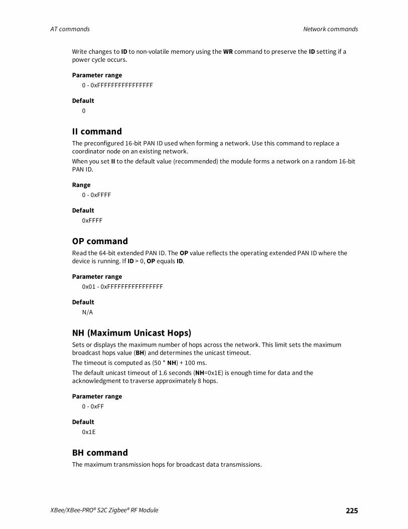
AT commands Network commands
XBee/XBee-PRO® S2C Zigbee® RF Module 225
Write changes to ID to non-volatile memory using the WR command to preserve the ID setting if apower cycle occurs.
Parameter range0 - 0xFFFFFFFFFFFFFFFF
Default0
II commandThe preconfigured 16-bit PAN ID used when forming a network. Use this command to replace acoordinator node on an existing network.When you set II to the default value (recommended) the module forms a network on a random 16-bitPAN ID.
Range0 - 0xFFFF
Default0xFFFF
OP commandRead the 64-bit extended PAN ID. The OP value reflects the operating extended PAN ID where thedevice is running. If ID > 0,OP equals ID.
Parameter range0x01 - 0xFFFFFFFFFFFFFFFF
DefaultN/A
NH (Maximum Unicast Hops)Sets or displays the maximum number of hops across the network. This limit sets the maximumbroadcast hops value (BH) and determines the unicast timeout.The timeout is computed as (50 * NH) + 100 ms.The default unicast timeout of 1.6 seconds (NH=0x1E) is enough time for data and theacknowledgment to traverse approximately 8 hops.
Parameter range0 - 0xFF
Default0x1E
BH commandThe maximum transmission hops for broadcast data transmissions.

AT commands Network commands
XBee/XBee-PRO® S2C Zigbee® RF Module 226
Parameter range0 - 0x1E
Default0
OI commandRead the 16-bit PAN ID. The OI value reflects the actual 16-bit PAN ID where the device is running.
Parameter range0 - 0xFFFF
Default[read-only]
NT (Node Discover Timeout)Sets or displays the amount of time a base node waits for responses from other nodes when using theND (Node Discover) command.When you issue the ND command, the transmission includes the NT value to provide all remotedevices with a response timeout. Remote devices wait a random time, less than NT, before sendingtheir response.
Parameter range0x20 - 0xFF (x 100 ms)
Default0x3C (6 seconds)
NO (Network Discovery Options)Set or read the network discovery options value for the ND (Network Discovery) command on aparticular device. The options bit field value changes the behavior of the ND command and whatoptional values the local device returns when it receives an ND command or API Node IdentificationIndicator (0x95) frame.
Parameter range0 - 0x03 (bit field)
Bit field
Option Description
0x01 Append the DD (Digi Device Identifier) value to ND responses or API node identificationframes.
0x02 Local device sends ND response frame when the ND is issued.
Default0x0

AT commands Network commands
XBee/XBee-PRO® S2C Zigbee® RF Module 227
SC (Scan Channels)Set or read the list of channels to scan.Coordinator - Bit field list of channels to choose from prior to starting network.Router/End Device - Bit field list of channels scanned to find a Coordinator/Router to join.Write changes to SC using the WR command to preserve the SC setting if a power cycle occurs.
Parameter range0 - 0xFFFF (bit field)
Bit field mask:
Bit Parameter
0 0x0B
1 0x0C
2 0x0D
3 0x0E
4 0x0F
5 0x10
6 0x11
7 0x12
8 0x13
9 0x14
10 0x15
11 0x16
12 0x17
13 0x18
14 0x19
15 0x1A
Note When you set SC to 0xFFFF on the device, Channel 26 is not allowed to transmit at more than 3dBm. If Channel 26 is present in the search mask (SC), active search (beaconing) for networkformation by a Coordinator is limited to no more than 3 dBm on all channels.Other communication by a Coordinator/Router/EndDevice, or active search for network joining(association) by Routers and End Devices is limited to no more than 3 dBm on Channel 26. PL and PMconfiguration settings control the transmit power on other channels.
n For the XBee-PRO SMT module, Channel 26 is not allowed to transmit at more than 6 dBm.
n For the XBee-PRO TH module, Channel 26 is not allowed to transmit at more than 2 dBm.

AT commands Network commands
XBee/XBee-PRO® S2C Zigbee® RF Module 228
Default0x7FFF
SD commandSets or displays the scan duration exponent. Write changes to SD using the WR command.
Note If you enable channel 26 (0x8000) in the search channel mask (SC), the device caps transmitpower on all channels at 3 dBm during network formation or joining.
Coordinator - Duration of the Active and Energy Scans (on each channel) used to determine anacceptable channel and PAN ID for the coordinator to startup on.Router/End Device - Duration of Active Scan (on each channel) used to locate an availablecoordinator/router to join during Association.Scan Time is measured as:
([# of channels to scan] * (2 ^SD) * 15.36 ms) + (38 ms * [# of channels to scan]) + 20 msUse the SC (Scan Channels) command to set the number of channels to scan. The XBee can scan up to16 channels (SC = 0xFFFF). The XBee-PRO can scan up to 13 channels (SC= 0x1FFE).SD influences the time the MAC listens for beacons or runs an energy scan on a given channel.
ExampleThe following table shows the results for a thirteen channel scan.
SD setting Time
0 0.200 s
2 0.799 s
4 3.190 s
6 12.780 s
Note SD influences the time the MAC listens for beacons or runs an energy scan on a given channel.The SD time is not a accurate estimate of the router/end device joining time requirements. Zigbeejoining adds additional overhead including beacon processing on each channel, and sending a joinrequest that extend the actual joining time.
Parameter range0 - 7 (exponent)0 - 0x0E
Default3
ED (Energy Detect)Start an Energy Detect scan. This command accepts an argument to specify the time in millisecondsto scan IEEE 802.15.4 channels 11 through 26. The device loops through all 16 channels until the timeelapses and returns the maximal energy on each channel. In Transparent mode, a comma must follow

AT commands Network commands
XBee/XBee-PRO® S2C Zigbee® RF Module 229
each value with the list ending with a carriage return. The values returned reflect the detected energylevel in units of -dBm. Convert an ED response of 49, 3A, and so on, to decimal to become -73 dBm, -58dBm, and so on.
Parameter range1 - 0xFF (x1 ms)
Default0x10 (16 ms)
ZS (Zigbee Stack Profile)Set or read the Zigbee stack profile value. This must be the same on all devices that will join the samenetwork. Effective with release 4x5E, changing ZS to a different value causes all current parametersto be written to persistent storage. While the stack profile is changing, CTS is de-asserted to preventserial input. We recommend CTS flow control.
Parameter range0 - 2
Default0
NJ (Node Join Time)Set or read the time that a Coordinator/Router allows nodes to join. You can changes this value at runtime without requiring a Coordinator or Router to restart. The time starts once the Coordinator orRouter starts, and the timer resets on power-cycle or when NJ changes.For an end device to enable rejoining, set NJ less than 0xFF on the device that joins. If NJ < 0xFF, thedevice assumes the network is not allowing joining and first tries to join a network using rejoining. Ifmultiple rejoining attempts fail, or if NJ = 0xFF, the device attempts to join using association.
Parameter range0 - 0xFF (x1 sec)
Default0xFF (always allows joining)
JV commandSet or read the channel verification parameter.If JV = 1, a router or end device verifies the coordinator is on its operating channel when joining orcoming up from a power cycle. If a coordinator is not detected, the router or end device leaves itscurrent channel and attempts to join a new PAN. If JV = 0, the router or end device continuesoperating on its current channel even if a coordinator is not detected.
Parameter range0 - 1

AT commands Network commands
XBee/XBee-PRO® S2C Zigbee® RF Module 230
Value Description
0 Channel verification disabled
1 Channel verification enabled
Default0
NW (Network Watchdog Timeout)Set or read the network watchdog timeout value.If NW is set > 0, the router monitors communication from the coordinator (or data collector) andleaves the network if it cannot communicate with the coordinator for 3 NW periods. The device resetsthe timer each time it receives or sends data to a coordinator, or if it receives a many-to-onebroadcast.
Parameter range0 - 0x64FF [x 1 minute](up to over 17 days)
Default0 (disabled)
JN (Join Notification)Set or read the join notification setting.If enabled, the device transmits a broadcast node identification packet on power up and when joining.This action blinks the Associate LED rapidly on all devices that receive the transmission, and sends anAPI frame out the serial port of API devices.Digi recommends you disable this feature for large networks to prevent excessive broadcasts.
Parameter range0 - 1
Default0
AR (Aggregate Routing Notification)Set or read the periodic time for broadcasting aggregate route messages. If used, these messagesenable many-to-one routing to the broadcasting device. Set AR to 0x00 to send only one broadcast, to0xFF to disable broadcasts, or to other values for periodic broadcasts in 10 second units.
Parameter range0 - 0xFF (x10 sec)
Default0xFF (disabled)
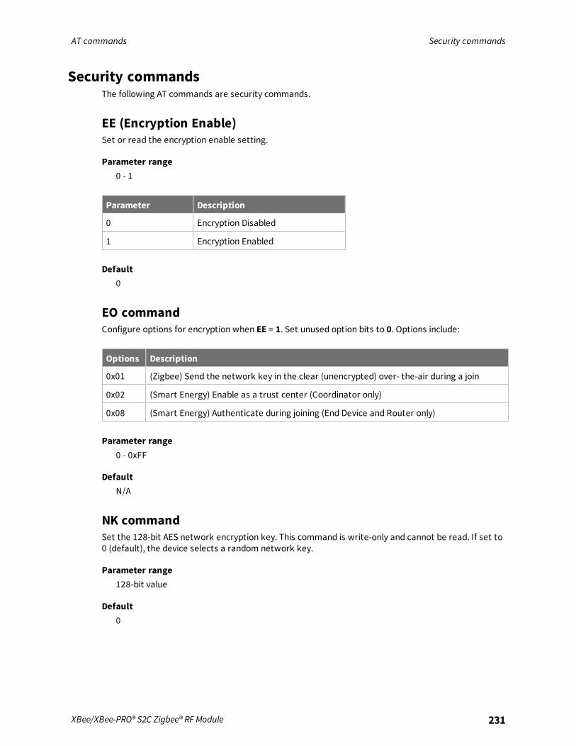
AT commands Security commands
XBee/XBee-PRO® S2C Zigbee® RF Module 231
Security commandsThe following AT commands are security commands.
EE (Encryption Enable)Set or read the encryption enable setting.
Parameter range0 - 1
Parameter Description
0 Encryption Disabled
1 Encryption Enabled
Default0
EO commandConfigure options for encryption when EE = 1. Set unused option bits to 0. Options include:
Options Description
0x01 (Zigbee) Send the network key in the clear (unencrypted) over- the-air during a join
0x02 (Smart Energy) Enable as a trust center (Coordinator only)
0x08 (Smart Energy) Authenticate during joining (End Device and Router only)
Parameter range0 - 0xFF
DefaultN/A
NK commandSet the 128-bit AES network encryption key. This command is write-only and cannot be read. If set to0 (default), the device selects a random network key.
Parameter range128-bit value
Default0

AT commands RF interfacing commands
XBee/XBee-PRO® S2C Zigbee® RF Module 232
KY (Link Key)Sets the 128-bit AES link key value that the device uses for encryption and decryption. This commandis write-only and cannot be read. If you set KY to 0 the coordinator transmits the network key in theclear to joining devices, and joining devices acquire the network key in the clear when joining.
Parameter range128-bit value
Default0
RF interfacing commandsThe following AT commands are RF interfacing commands.
PL (TX Power Level)Sets or displays the power level at which the device transmits conducted power.For XBee-PRO, PL= 4 is calibrated and the remaining power levels are approximate. The devicerecalibrates its power setting every 15 seconds based on factory calibration settings, the currenttemperature and the amount of voltage over the typical 3.3 V. If the input voltage is too high, thedevice resets.For XBee, PL = 4, PM = 1 is tested at the time of manufacturing. Other power levels are approximate.On channel 26, transmitter power will not exceed +3 dBm output.
Parameter rangeThese parameters equate to the following settings for the XBee RF module (boost mode disabled):
Setting Power level
0 -5 dBm
1 -1 dBm
2 +1 dBm
3 +3 dBm
4 +5 dBm
These parameters equate to the following settings for the XBee-PRO RF module (boost modeenabled):
Setting Power level
0 0 dBm (approximate)
1 +12 dBm (approximate)
2 +14 dBm (approximate)

AT commands RF interfacing commands
XBee/XBee-PRO® S2C Zigbee® RF Module 233
Setting Power level
3 +16 dBm (approximate)
4 +18 dBM
Default4
PM (Power Mode)Set or read the power mode of the device. Enabling boost mode improves the receive sensitivity by2dB and increase the transmit power by 3dB.
Parameter range0 - 1
Setting Meaning
0 Boost mode disabled
1 Boost mode enabled
Default1
DB commandThis command reports the received signal strength of the last received RF data packet or APSacknowledgment. The DB command only indicates the signal strength of the last hop. It does notprovide an accurate quality measurement for a multihop link.The DB command value is measured in -dBm. For example, if DB returns 0x50, then the RSSI of the lastpacket received was -80 dBm. Set DB to 0 to clear the current value, and it will be updated with thenext valid packet received.
Parameter rangeObserved ranges:XBee-PRO - 0x1A - 0x58XBee- 0x 1A - 0x5C
DefaultN/A
PP commandReads the dBm output when you select maximum power (PL4).
Note Read the maximum allowed power level when device is configured with PL=4. Use this commandto determine if the module is a Pro or non-Pro variant. The value the command returns will be in hexrepresentation: Pro = 0x14 and Non-Pro = 0x8.

AT commands Serial interfacing commands
XBee/XBee-PRO® S2C Zigbee® RF Module 234
Parameter range0x0 - 0x12
Default[read-only]
Serial interfacing commandsThe following AT commands are serial interfacing commands.
API EnableEnables API Mode. The device ignores this command when using SPI. API mode 1 is always used.
Parameter range0 - 2
Parameter Description
0 API disabled (operate in Transparent mode)
1 API enabled
2 API enabled (with escaped control characters)
Default0
AO commandConfigure the options for API. The current options select the type of receive API frame to send out theUART for received RF data packets.
Parameter range0 - 3
Parameter Description
0 Default API Rx Indicator enabled
1 Default API Explicit Rx Indicator - 0x91, this is for Explicit Addressing data frames.
3 Enable ZDO passthrough of ZDO requests to the serial port that are not supported bythe stack, as well as Simple_Desc_req, Active_EP_req, and Match_Desc_req.
Default0

AT commands Serial interfacing commands
XBee/XBee-PRO® S2C Zigbee® RF Module 235
BD (Interface Data Rate)The device interprets any value above 0x0A as an actual baud rate. Standard baud rates up to 115200are supported. Non-standard baud rates above 115200 are permitted but their performance is notguaranteed.
Parameter rangeStandard baud rates: 0x0 - 0x0A
Value Description
0x1 2,400 b/s
0x2 4,800 b/s
0x3 9,600 b/s
0x4 19,200 b/s
0x5 38,400 b/s
0x6 57,600 b/s
0x7 115,200 b/s
0x8 230,400 b/s
0x9 460,800 b/s
0xA 921,600 b/s
Default0x03 (9600 b/s)
NB (Parity)Set or read the serial parity settings for UART communications.
Parameter range
Parameter Description
0x00 No parity
0x01 Even parity
0x02 Odd parity
0x03 Mark parity
Default0x00
SB commandSets or displays the number of stop bits for UART communications.

AT commands Serial interfacing commands
XBee/XBee-PRO® S2C Zigbee® RF Module 236
Parameter range0 - 1
Parameter Configuration
0 One stop bit
1 Two stop bits
Default0
RO commandSet or read the number of character times of inter-character silence required before transmissionbegins when operating in Transparent mode.Set RO to 0 to transmit characters as they arrive instead of buffering them into one RF packet. TheRO command is only supported when operating in Transparent mode.
Parameter range0 - 0xFF (x character times)
Default3
D7 (DIO7/CTS)Sets or displays the DIO7/CTS configuration (TH pin 12/SMT pin 25).
Parameter range0, 1, 3 - 7
Parameter Description
0 Unmonitored digital input
1 CTS flow control
3 Digital input
4 Digital output, low
5 Digital output, high
6 RS-485 Tx enable, low Tx
7 RS-485 Tx enable high, high Tx
Default0x1

AT commands I/O settings commands
XBee/XBee-PRO® S2C Zigbee® RF Module 237
D6 (DIO6/RTS)Sets or displays the DIO6/RTS configuration (TH pin 16/SMT pin 29).
Parameter range0, 1, 3 - 5
Parameter Description
0 Unmonitored digital input
1 RTS flow control
3 Digital input
4 Digital output, low
5 Digital output, high
Default0
I/O settings commandsThe following AT commands are I/O settings commands.t b
IR (I/O Sample Rate)Set or read the I/O sample rate to enable periodic sampling.If you set the I/O sample rate to greater than 0, the device samples and transmits all enabled digitalI/O and analog inputs every IRmilliseconds. I/O Samples transmit to the address specified by DT.To enable periodic sampling, set IR to a non-zero value, and enable the analog or digital I/Ofunctionality of at least one device pin. The sample rate is measured in milliseconds.For more information, see the following commands:
n D0 (AD0/DIO0 Configuration) through D9 (DIO9/ON_SLEEP).
n P0 (RSSI/PWM0 Configuration) through P4 (DIO14/DIN).
WARNING! If you set IR to 1 or 2, the device will not keep up andmany samples will belost.
Parameter range0, 0x32 - 0xFFFF (ms)
Default0
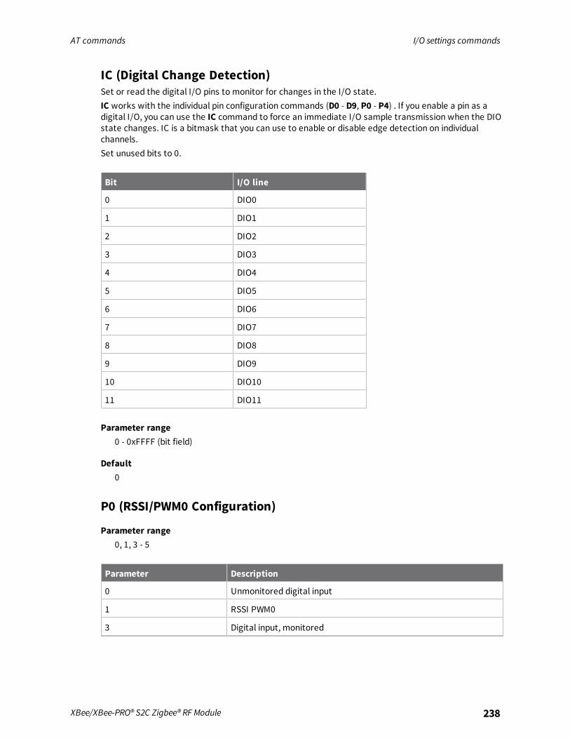
AT commands I/O settings commands
XBee/XBee-PRO® S2C Zigbee® RF Module 238
IC (Digital Change Detection)Set or read the digital I/O pins to monitor for changes in the I/O state.IC works with the individual pin configuration commands (D0 - D9, P0 - P4) . If you enable a pin as adigital I/O, you can use the IC command to force an immediate I/O sample transmission when the DIOstate changes. IC is a bitmask that you can use to enable or disable edge detection on individualchannels.Set unused bits to 0.
Bit I/O line
0 DIO0
1 DIO1
2 DIO2
3 DIO3
4 DIO4
5 DIO5
6 DIO6
7 DIO7
8 DIO8
9 DIO9
10 DIO10
11 DIO11
Parameter range0 - 0xFFFF (bit field)
Default0
P0 (RSSI/PWM0 Configuration)
Parameter range0, 1, 3 - 5
Parameter Description
0 Unmonitored digital input
1 RSSI PWM0
3 Digital input, monitored

AT commands I/O settings commands
XBee/XBee-PRO® S2C Zigbee® RF Module 239
Parameter Description
4 Digital output, default low
5 Digital output, default high
Default1
P1 (DIO11/PWM1 Configuration)Sets or displays the DIO11 configuration (TH pin 7/SMT pin 8).
Parameter range0, 1, 3 - 5
Parameter Description
0 Unmonitored digital input
1 Output 50% duty cycle clock at 32.787 kHz
3 Digital input, monitored
4 Digital output, default low
5 Digital output, default high
Default0
P2 (DIO12 Configuration)Sets or displays the DIO12 configuration (TH pin 4/SMT pin 5).
Parameter range
Parameter Description
0 Unmonitored digital input
1 SPI_MISO
3 3- Digital input, monitored
4 4- Digital output, default low
5 Digital output, default high
Default0

AT commands I/O settings commands
XBee/XBee-PRO® S2C Zigbee® RF Module 240
P3 (DIO13/DOUT Configuration)Sets or displays the DIO13 configuration (TH pin 2/SMT pin 3).
Parameter range0, 1, 3 - 5
Parameter Description
0 Unmonitored digital input
1 Data out for UART
3 Monitored digital input
4 Digital output low
5 Digital output high
Default1
P4 (DIO14/DIN)Sets or displays the DIO14 configuration (TH pin 3/SMT pin 4).
Parameter range0, 1, 3 - 5
Parameter Description
0 Unmonitored digital input
1 Data in for UART
3 Digital input
4 Digital output low
5 Digital output high
Default1
P5 (DIO15/SPI_MISO)Sets or displays the DIO15/SPI_MISO configuration (TH pin 4/SMT pin 17).This only applies to surface-mount devices.
Parameter range0, 1

AT commands I/O settings commands
XBee/XBee-PRO® S2C Zigbee® RF Module 241
Parameter Description
0 Unmonitored digital input
1 Output from SPI port
Default1
P6 (SPI_MOSI Configuration)Sets or displays the DIO16/SPI_MOSI configuration (TH pin 11/SMT pin 16).This only applies to surface-mount devices.
Parameter range0, 10, 4, 5
Parameter Description
0 Unmonitored digital input
1 Input to SPI port
Default1
P7 (DIO17/SPI_SSEL )Sets or displays the DIO17/SPI_SSEL configuration (TH pin 17/SMT pin 15).This only applies to surface-mount devices.
Parameter range0, 1
Parameter Description
0 Unmonitored digital input
1 Input to select the SPI port
Default1
P8 (DIO18/SPI_SCLK)Sets or displays the DIO18/SPI_SCLK configuration (TH pin 18/SMT pin 14).This only applies to surface-mount devices.
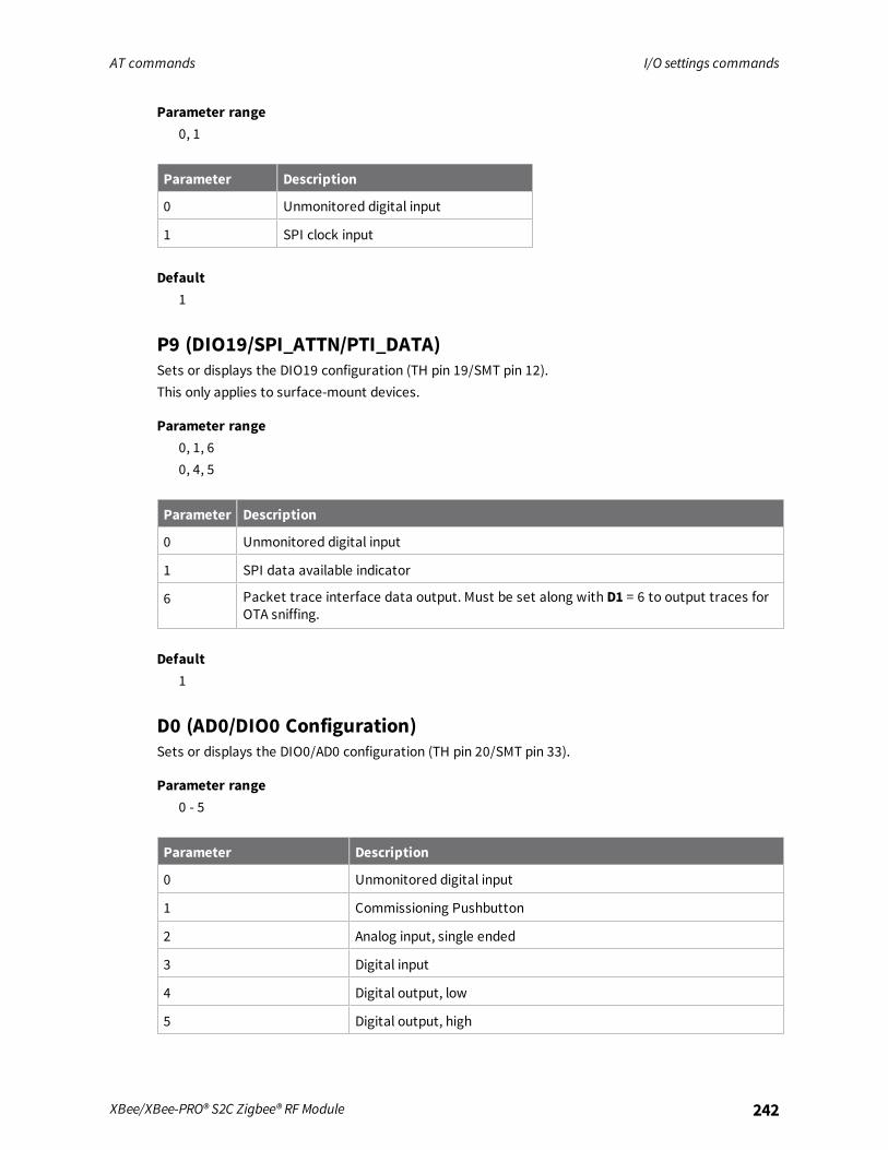
AT commands I/O settings commands
XBee/XBee-PRO® S2C Zigbee® RF Module 242
Parameter range0, 1
Parameter Description
0 Unmonitored digital input
1 SPI clock input
Default1
P9 (DIO19/SPI_ATTN/PTI_DATA)Sets or displays the DIO19 configuration (TH pin 19/SMT pin 12).This only applies to surface-mount devices.
Parameter range0, 1, 60, 4, 5
Parameter Description
0 Unmonitored digital input
1 SPI data available indicator
6 Packet trace interface data output. Must be set along with D1 = 6 to output traces forOTA sniffing.
Default1
D0 (AD0/DIO0 Configuration)Sets or displays the DIO0/AD0 configuration (TH pin 20/SMT pin 33).
Parameter range0 - 5
Parameter Description
0 Unmonitored digital input
1 Commissioning Pushbutton
2 Analog input, single ended
3 Digital input
4 Digital output, low
5 Digital output, high

AT commands I/O settings commands
XBee/XBee-PRO® S2C Zigbee® RF Module 243
Default1
D1 (AD1/DIO1/PTI_En Configuration)Sets or displays the AD1/DIO1/PTI_En configuration TH pin 19/SMT pin 32.
Parameter range0 - 6
Parameter Description
0 Unmonitored digital input
1 SPI_ATTN - Analog input, single ended for the through-hole device
2 Analog input, single ended
3 Digital input
4 Digital output, low
5 Digital output, high
6 Packet trace interface enable. Must be set along with P9= 6 to output traces for OTAsniffing.
Default0
D2 (AD2/DIO2 Configuration)Sets or displays the DIO2/AD2 configuration (TH pin 18/SMT pin 31).
Parameter range0 - 50 - 1
Parameter Description
0 Unmonitored digital input
1 SPI_CLK for through-hole devices
2 Analog input, single ended
3 Digital input
4 Digital output, low
5 Digital output, high
Default0

AT commands I/O settings commands
XBee/XBee-PRO® S2C Zigbee® RF Module 244
D3 (AD3/DIO3 Configuration)Sets or displays the DIO3/AD3 configuration (TH pin 17/SMT pin 30).
Parameter range0 - 5
Parameter Description
0 Unmonitored digital input
1 SPI_SSEL for the through-hole device
2 Analog input, single ended
3 Digital input
4 Digital output, low
5 Digital output, high
Default0
D4 (DIO4 Configuration)Sets or displays the DIO4 configuration (TH pin 11/SMT pin 24).
Parameter range0, 1, 3 - 5
Parameter Description
0 Unmonitored digital input
1 SPI_MOSI for the through-hole device
3 Digital input
4 Digital output, low
5 Digital output, high
Default0
D5 (DIO5/Associate Configuration)Sets or displays the DIO5 configuration (TH pin 15/SMT pin 28).
Parameter range0, 1, 3 - 5
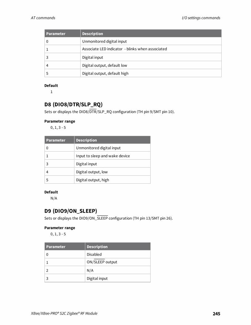
AT commands I/O settings commands
XBee/XBee-PRO® S2C Zigbee® RF Module 245
Parameter Description
0 Unmonitored digital input
1 Associate LED indicator - blinks when associated
3 Digital input
4 Digital output, default low
5 Digital output, default high
Default1
D8 (DIO8/DTR/SLP_RQ)Sets or displays the DIO8/DTR/SLP_RQ configuration (TH pin 9/SMT pin 10).
Parameter range0, 1, 3 - 5
Parameter Description
0 Unmonitored digital input
1 Input to sleep and wake device
3 Digital input
4 Digital output, low
5 Digital output, high
DefaultN/A
D9 (DIO9/ON_SLEEP)Sets or displays the DIO9/ON_SLEEP configuration (TH pin 13/SMT pin 26).
Parameter range0, 1, 3 - 5
Parameter Description
0 Disabled
1 ON/SLEEP output
2 N/A
3 Digital input
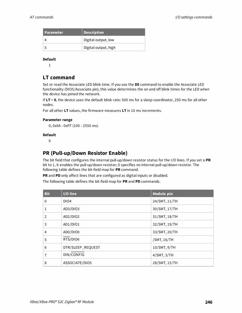
AT commands I/O settings commands
XBee/XBee-PRO® S2C Zigbee® RF Module 246
Parameter Description
4 Digital output, low
5 Digital output, high
Default1
LT commandSet or read the Associate LED blink time. If you use the D5 command to enable the Associate LEDfunctionality (DIO5/Associate pin), this value determines the on and off blink times for the LED whenthe device has joined the network.If LT = 0, the device uses the default blink rate: 500 ms for a sleep coordinator, 250 ms for all othernodes.For all other LT values, the firmware measures LT in 10 ms increments.
Parameter range0, 0x0A - 0xFF (100 - 2550 ms)
Default0
PR (Pull-up/Down Resistor Enable)The bit field that configures the internal pull-up/down resistor status for the I/O lines. If you set a PRbit to 1, it enables the pull-up/down resistor; 0 specifies no internal pull-up/down resistor. Thefollowing table defines the bit-field map for PR command.PR and PD only affect lines that are configured as digital inputs or disabled.The following table defines the bit-field map for PR and PD commands.
Bit I/O line Module pin
0 DIO4 24/SMT, 11/TH
1 AD3/DIO3 30/SMT, 17/TH
2 AD2/DIO2 31/SMT, 18/TH
3 AD1/DIO1 32/SMT, 19/TH
4 AD0/DIO0 33/SMT, 20/TH
5 RTS/DIO6 /SMT, 16/TH
6 DTR/SLEEP_REQUEST 10/SMT, 9/TH
7 DIN/CONFIG 4/SMT, 3/TH
8 ASSOCIATE/DIO5 28/SMT, 15/TH

AT commands I/O settings commands
XBee/XBee-PRO® S2C Zigbee® RF Module 247
Bit I/O line Module pin
9 On/SLEEP/DIO9 26/SMT, 13/TH
10 DIO12 5/SMT, 4/TH
11 PWM0/RSSI/DIO10/ 7/SMT, 6/TH
12 PWM1/DIO11 8/SMT, 7/TH
13 CTS/DIO7 25/SMT, 12/TH
14 DOUT/DIO13 3/SMT, 2/TH
Parameter range0 - 0x7FFF (bit field)
Default0x1FFF
PD (Pull Up/Down Direction)The resistor pull direction bit field (1 = pull-up, 0 = pull-down) for corresponding I/O lines that are setby the PR command.If the bit is set, the device uses an internal pull-up resistor. If it is clear, the device uses an internalpull-down resistor. See the PR command for the bit order.
Parameter range0x0 - 0x7FFF
Default0x1FBF
RP commandThe PWM timer expiration in 0.1 seconds. RP sets the duration of pulse width modulation (PWM) signaloutput on the RSSI pin. The signal duty cycle updates with each received packet and shuts off whenthe timer expires.When RP = 0xFF, the output is always on.
Parameter range0 - 0xFF (x 100 ms)
Default0x28 (four seconds)
DC commandBit settings to enable or disable certain behaviors.
Bit field:Bit settings to enable or disable certain behaviors.

AT commands I/O settings commands
XBee/XBee-PRO® S2C Zigbee® RF Module 248
Bit Description
0 Generate a preconfigured link key using the device’s install code (KY will be ignored).
1 Network Leave Request Not Allowed. Indicates if a router node discards or accepts networkleave commands.
2 Reserved
3 Reserved
4 Verbose Joining Mode. See Extended Modem Status frame - 0x98 for a full description.
Parameter range0 - 0xFFFF
Default0x00
DO commandSets or displays the device options.
Bit field:
Bit Description
0 Reserved
1 Reserved for Smart Energy devices.
2 0/1 = First or Best Join. First join means the device joins the network through the firstacceptable Beacon response it receives. Best join means the device joins the network throughthe strongest Beacon response it receives after searching all search mask channels.
3 Disable NULL transport key (coordinator only).
4 Disable Tx packet extended timeout.
5 Disable ACK for end device I/O sampling.
6 Enable high ram concentrator.
7 Enable NW to find new network before leaving the network.
Parameter range0x00 - 0xFF
Default0x00
%V (Voltage Supply Monitoring)Reads the voltage on the Vcc pin in mV.

AT commands Diagnostic commands
XBee/XBee-PRO® S2C Zigbee® RF Module 249
Parameter range0 - 0xFFFF [read only]
DefaultN/A
V+ (Voltage Supply Monitoring)Set the voltage supply threshold with the V+ command. If the measured supply voltage falls below orequal to this threshold, the supply voltage appends to the I/O sample set, and sets bit 7 of the AnalogChannel Mask. Set V+ to 0 by default (do not include the supply voltage). The units of this commandare mV. For example, to include a measurement of the supply voltage when it falls below 2.7 V, set V+to 2700 = 0xA8A.
Parameter range0 - 0xFFFF
Default0
TP (Temperature)The current module temperature in degrees Celsius. The accuracy is ± 7 degrees. 1 °C = 0x0001 and -1°C = 0xFFFF.
Note This command is only available on the XBee-PRO device.
Parameter range0x0 - 0xFFFF
DefaultN/A
Diagnostic commandsThe following commands are diagnostic commands.
VR commandReads the firmware version on a device as a 4-digit hex number.
Parameter range0 - 0xFFFF [read-only]
DefaultSet in the factory

AT commands Diagnostic commands
XBee/XBee-PRO® S2C Zigbee® RF Module 250
VL commandShows detailed version information, device type, time stamp for the build, Ember stack version, andbootloader version.
Parameter rangeN/A
DefaultN/A
HV commandDisplay the hardware version number of the device.Read the device's hardware version. Use this command to distinguish between different hardwareplatforms. The upper byte returns a value that is unique to each device type. The lower byte indicatesthe hardware revision.
Note The XBee returns a value of 0x22xx for this command. The XBee-PRO returns a value of 0x21xx.
Parameter range0 - 0xFFFF [read-only]
DefaultSet in firmware
AI commandRead information regarding last node join request.
Statuscode Meaning
0x00 Successfully formed or joined a network. (Coordinators form a network, routers and enddevices join a network).
0x21 Scan found no PANs.
0x22 Scan found no valid PANs based on current SC and ID settings.
0x23 Valid Coordinator or Routers found, but they are not allowing joining (NJ expired).
0x24 No joinable beacons were found.
0x25 Unexpected state, node should not be attempting to join at this time.
0x27 Node Joining attempt failed (typically due to incompatible security settings).
0x2A Coordinator Start attempt failed.
0x2B Checking for an existing coordinator.
0x2C Attempt to leave the network failed.

AT commands Command mode options
XBee/XBee-PRO® S2C Zigbee® RF Module 251
Statuscode Meaning
0xAB Attempted to join a device that did not respond.
0xAD Secure join error - network security key not received.
0xAF Secure join error - joining device does not have the right preconfigured link key.
0xFF Initialization time; no association status has been determined yet.
Applications should read AI until it returns 0x00, indicating a successful startup (coordinator) or join(routers and end devices).
Parameter range0 - 0xFF [read-only]
DefaultN/A
Command mode optionsThe following commands are Commandmode option commands.
CT commandSets or displays the Commandmode timeout parameter. If a device does not receive any validcommands within this time period, it returns to Idle mode from Commandmode.
Parameter range2 - 0x28F
Default0x64 (10 seconds)
CN commandImmediately exits Command Mode and applies pending changes.
Parameter rangeN/A
DefaultN/A
GT commandSet the required period of silence before and after the command sequence characters of theCommandmode sequence (GT + CC + GT). The period of silence prevents inadvertently enteringCommandmode.
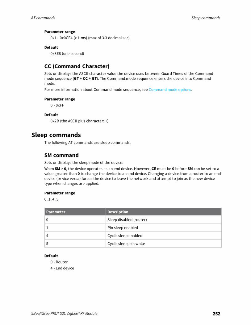
AT commands Sleep commands
XBee/XBee-PRO® S2C Zigbee® RF Module 252
Parameter range0x1 - 0x0CE4 (x 1 ms) (max of 3.3 decimal sec)
Default0x3E8 (one second)
CC (Command Character)Sets or displays the ASCII character value the device uses between Guard Times of the Commandmode sequence (GT + CC + GT). The Commandmode sequence enters the device into Commandmode.For more information about Commandmode sequence, see Commandmode options.
Parameter range0 - 0xFF
Default0x2B (the ASCII plus character: +)
Sleep commandsThe following AT commands are sleep commands.
SM commandSets or displays the sleepmode of the device.When SM > 0, the device operates as an end device. However, CEmust be 0 before SM can be set to avalue greater than 0 to change the device to an end device. Changing a device from a router to an enddevice (or vice versa) forces the device to leave the network and attempt to join as the new devicetype when changes are applied.
Parameter range0, 1, 4, 5
Parameter Description
0 Sleep disabled (router)
1 Pin sleep enabled
4 Cyclic sleep enabled
5 Cyclic sleep, pin wake
Default0 - Router4 - End device

AT commands Sleep commands
XBee/XBee-PRO® S2C Zigbee® RF Module 253
SN commandSet or read the number of sleep periods value. This command controls the number of sleep periodsthat must elapse between assertions of the ON_SLEEP line during the wake time if no RF data iswaiting for the end device. This command allows a host application to sleep for an extended time if noRF data is present.
Parameter range1 - 0xFFFF
Default1
SP (Sleep Period)Sets the duration of sleep time for the end device, up to 28 seconds. Use the SN command to extendthe sleep time past 28 seconds.On the parent, this value determines how long the parent buffers a message for the sleeping enddevice. Set the value to at least equal to the longest SP time of any child end device.
Parameter range0x20 - 0xAF0 x 10ms (Quarter second resolution)
Default0x20
ST (Time before Sleep)Sets or displays the wake time of the device.The timer resets each time the device receives serial or RF data. Once the timer expires, an enddevice may enter low power operation. This applies to cyclic sleep end devices only.
Parameter range1 - 0xFFFF (x 1 ms)
Default0x1388 (5 seconds)
SO commandSet or read the sleep options bit field of a device. This command is a bitmask.Set unused option bits to 0. Sleep options should not be used for most applications. See Manage EndDevices.
Parameter range0 - 0xFF

AT commands Sleep commands
XBee/XBee-PRO® S2C Zigbee® RF Module 254
Bit Option
0x02 Always wake for ST time
0x04 Sleep entire SN * SP time
Default0
WH (Wake Host Delay)Sets or displays the wake host timer value. You can use WH to give a sleeping host processorsufficient time to power up after the device asserts the ON_SLEEP line.If you set WH to a non-zero value, this timer specifies a time in milliseconds that the device delaysafter waking from sleep before sending data out the UART or transmitting an I/O sample. If the devicereceives serial characters, the WH timer stops immediately.
Parameter range0 - 0xFFFF (x 1 ms)
Default0
PO commandSet or read the end device poll rate.Setting this to 0 (default) enables polling at 100 ms (default rate), advancing in 10 ms increments.Adaptive polling may allow the end device to poll more rapidly for a short time when receiving RF data.

AT commands Execution commands
XBee/XBee-PRO® S2C Zigbee® RF Module 255
Parameter range0 - 0x3E8
Default0
Execution commandsThe location where most AT commands set or query register values, execution commands execute anaction on the device. Execution commands are executed immediately and do not require changes tobe applied.
AC (Apply Changes)Immediately applies new settings without exiting Commandmode.Applies changes to all command registers and applies queued command register values. For example,changing the serial interface rate with the BD command does not change the UART interface rateuntil changes are applied with the AC command. The CN command and 0x08 API command frame alsoapply changes.
Parameter rangeN/A
DefaultN/A
AS commandScans the neighborhood for beacon responses. The AS command is only valid as a local command.Response frames are structured as:AS_type – unsigned byte = 2 - ZB firmware uses a different format than XBee Wi-Fi , which is type 1Channel – unsigned bytePAN – unsigned word in big endian formatExtended PAN – eight unsigned bytes in bit endian formatAllow Join – unsigned byte – 1 indicates join is enabled, 0 that it is disabledStack Profile – unsigned byteLQI – unsigned byte, higher values are betterRSSI – signed byte, lower values are better
Parameter range
DefaultN/A
WR commandWrites parameter values to non-volatile memory so that parameter modifications persist throughsubsequent resets.

AT commands Execution commands
XBee/XBee-PRO® S2C Zigbee® RF Module 256
Note Once you issue a WR command, do not send any additional characters to the device until afteryou receive the OK response.
Parameter rangeN/A
DefaultN/A
RE commandThis command sets all parameters except ZS and KY to their default values. To change ZS and KY, youmust explicitly set them. In order for the default parameters to persist through subsequent resets,send a separate WR command after RE. Read-only parameters are not directly affected by RE andreflect the current state of the device.
Parameter rangeN/A
DefaultN/A
FR (Software Reset)Resets the device. The device responds immediately with anOK and performs a reset 100 ms later.If you issue FRwhile the device is in Command Mode, the reset effectively exits Commandmode.
Parameter rangeN/A
DefaultN/A
NR (Network Reset)Resets network layer parameters on one or more modules within a PAN. Responds immediately withanOK then causes a network restart. The device loses all network configuration and routinginformation.If NR = 0: Resets network layer parameters on the node issuing the command.If NR = 1: Sends broadcast transmission to reset network layer parameters on all nodes in the PAN.
Note NR andNR0 both perform the same function andmay be used interchangeably.
Parameter range0 - 1
DefaultN/A

AT commands Execution commands
XBee/XBee-PRO® S2C Zigbee® RF Module 257
SI commandCauses a cyclic sleep device to sleep immediately rather than wait for the ST timer to expire.
Note This command only has effect in API mode (sleeps immediately whether given as a 0x08 or 0x09API frame), and no effect in AT commandmode. AT commandmode is exited only by the CN commandor by timeout.
Note If you issue this command in Command Mode, the module remains in commandmode until theCT timer expires or you issue a CN command.
ParameterN/A
DefaultN/A
CB commandUse CB to simulate commissioning pushbutton presses in software.Set the parameter value to the number of button presses that you want to simulate. For example,send CB1 to perform the action of pressing the Commissioning Pushbutton once.See Commissioning pushbutton.
Parameter range1, 2, 4
DefaultN/A
&X (Clear Binding and Group Tables)Resets the binding and group tables.
Parameter rangeN/A
DefaultN/A
ND (Node Discovery)The command reports the following information after a jittered time delay.
PARENT_NETWORK ADDRESS<CR> (2 Bytes) (always 0xFFFE)PARENT_NETWORK ADDRESS (2 Bytes) <CR>DEVICE_TYPE<CR> (1 Byte: 0 = Coordinator, 1 = Router, 2 = End Device)STATUS<CR> (1 Byte: Reserved)PROFILE_ID<CR> (2 Bytes)MANUFACTURER_ID<CR> (2 Bytes)

AT commands Execution commands
XBee/XBee-PRO® S2C Zigbee® RF Module 258
<CR>After (NT * 100) milliseconds, the command ends by returning a <CR>.If you send ND through a local API frame, the device returns each response as a separate AT_CMD_Response packet. The data consists of the above listed bytes without the carriage return delimiters.The NI string end in a “0x00” null character.ND also accepts a NI (Node Identifier) as a parameter (optional). In this case, only a device thatmatches the supplied identifier responds after a jittered time delay. If there are no matching devices,the command returns an “ERROR”.The jittered time delay is based on the NT setting.The radius of the ND command is set by the BH command.A status code of 1=ERROR will be returned if the transmit queue is full. That means there are alreadyfour messages queued for transmission. The application is trying to sendmessages faster than thedevice can process the requests. The application may either try again later, be redesigned to sendmessages at a slower rate, or wait for a Tx Status response for a prior message before attempting tosend another.For more information about the options that affect the behavior of the ND command, see NO(Network Discovery Options).
Parameter range20-byte printable ASCII string
DefaultASCII space character (0x20)
DN (Destination Node)Resolves an NI (Node identifier) string to a physical address (case sensitive).The following events occur after DN discovers the destination node:When DN is sent in Commandmode (AT firmware):
1. The device sets DL and DH to the address of the device with the matching NI string.The address selected (either 16-bit short address or 64-bit extended address) is chosen basedon the destination device's MY command configuration.
2. The receiving device returns OK (or ERROR).
3. The device exits Commandmode to allow for immediate communication. If an ERROR isreceived, then Commandmode does not exit.
When DN is sent as a local AT Command API frame (API firmware):1. The receiving device returns the 16-bit network and 64-bit extended addresses in an API
Command Response frame.
2. If there is no response from a module within (NT* 100) milliseconds or you do not specify aparameter (by leaving it blank), the receiving device returns an ERROR message. In the case ofan ERROR, the device does not exit commandmode. Set the radius of the DN command usingthe BH command.
Parameter rangeUp to 20-byte printable ASCII string

AT commands Execution commands
XBee/XBee-PRO® S2C Zigbee® RF Module 259
DefaultN/A
DJ (Disable Joining)Prevent a local device from joining a network.
Note This parameter is not written to flash with the WR command and reverts to default after apower cycle.
Parameter range0 - 1
Value Description
0 Join enabled
1 Join disabled
Default0
IS commandForces a read of all enabled digital and analog input lines.
Parameter rangeN/A
DefaultN/A

Module support
This section provides customization information for the XBee/XBee-PRO Zigbee RF Module. You cancustomize default parameters, or write or load custom firmware for the Ember EM357 chip.
Configure the device using XCTU 261Software libraries 261Customize XBee Zigbee firmware 261XBee bootloader 261Serial firmware updates 262Invoke the XBee bootloader 262Send a firmware image 262Writing custom firmware 262
XBee/XBee-PRO® S2C Zigbee® RF Module 260

Module support Configure the device using XCTU
XBee/XBee-PRO® S2C Zigbee® RF Module 261
Configure the device using XCTUXBee Configuration and Test Utility (XCTU) is a multi-platform program that enables users to interactwith Digi radio frequency (RF) devices through a graphical interface. The application includes built-intools that make it easy to set up, configure, and test Digi RF devices.For instructions on downloading and using XCTU, see the XCTU User Guide.
Software librariesOne way to communicate with the XBee/XBee-PRO Zigbee RF Module is by using a software library.The libraries available for use with the XBee/XBee-PRO Zigbee RF Module include:
n XBee Java library
n XBee Python library
The XBee Java Library is a Java API. The package includes the XBee library, its source code and acollection of samples that help you develop Java applications to communicate with your XBee devices.The XBee Python Library is a Python API that dramatically reduces the time to market of XBeeprojects developed in Python and facilitates the development of these types of applications, making itan easy process.
Customize XBee Zigbee firmwareOnce device parameters are tested in an application and finalized, we can manufacture devices withspecific, customer-defined configurations. These custom configurations can lock in a firmware versionor set command values when the devices are manufactured, eliminating the need for customers toadjust device parameters on arrival. Alternatively, we can program custom firmware, includingEmber's EZSP UART image, into the devices during manufacturing. Contact Digi to create a customconfiguration.
XBee bootloaderXBee devices use a modified version of Ember’s bootloader. This bootloader version supports acustom entry mechanism that uses module pins DIN (TH pin 4/SMT pin 4), DTR / SLEEP_RQ (TH pin9/SMT pin 10), and RTS (TH pin 16/SMT pin 29).To invoke the bootloader, do the following:
1. Set DTR/SLEEP_RQ low (TTL 0V) and RTS high.
2. Send a serial break to the DIN pin and power cycle or reset the module.
3. When the device powers up, set DTR/SLEEP_RQ and DIN to low (TTL 0V) and RTS should behigh.
4. Terminate the serial break and send a carriage return at 115200 baud to the device.
5. If successful, the device sends the Ember bootloader menu out the DOUT pin at 115200 baud.
6. You can send commands can be sent to the bootloader at 115200 b/s.
Note Disable hardware flow control when entering and communicating with the Ember 357bootloader.
All serial communications with the module use 8 data bits, no parity bit, and 1 stop bit.

Module support Serial firmware updates
XBee/XBee-PRO® S2C Zigbee® RF Module 262
You can update firmware on the XBee3 Zigbee RF Module serially. This is done by invoking the XBee3bootloader and transferring the firmware image using XMODEM.
Serial firmware updatesYou can update firmware on the XBee/XBee-PRO Zigbee RF Module serially.Serial firmware updates use the XBee custom bootloader which ships in all units. This bootloader isbased on Ember's standalone bootloader, but with a modified entry mechanism. The modified entrymechanism uses device pins 4, 10, and 29 (DIN, DTR, and RTS respectively) on the SMT, and pins 3, 9,16 on the TH.XCTU can update firmware serially on the XBee/XBee-PRO Zigbee RF Module. Contact Digi support fordetails.If an application requires custom firmware to update the XBee firmware serially, proceed to Invokethe XBee bootloader.
Invoke the XBee bootloaderSee XBee bootloader for steps to invoke the bootloader using RS-232 signals. You can also invoke thebootloader by issuing a command using XCTU. The application makes an explicit call to the bootloader,which does not return.If there is no valid application, the bootloader always runs.
Send a firmware imageAfter invoking the bootloader, the Ember bootloader sends the bootloader menu characters out theserial port, which may be the UART at 115200 b/s or the SPI, where the attached SPI master providesthe clock rate. To upload a firmware image:
1. Look for the bootloader prompt BL > to ensure the bootloader is active.
2. Send an ASCII 1 character to initiate a firmware update.
3. After sending a 1, the device waits for an XModem CRC upload of a .ebl image over the serialline at 115200 b/s. Send the .ebl file to the device in order.
If the firmware image is successfully loaded, the bootloader outputs a “complete” string. Invoke thenewly loaded firmware by sending a 2 to the device.If the firmware image is not successfully loaded, the bootloader outputs an "aborted string". It returnto the main bootloader menu. Some causes for failure are:
n Over 1 minute passes after the command to send the firmware image and the first block of theimage has not yet been sent.
n A power cycle or reset event occurs during the firmware load.
n A file error or a flash error occurs during the firmware load.
Writing custom firmwareYou can use the XBee module as a hardware development platform for the EM357. You can developcustom firmware images around the EmberZNet 4.2.xx mesh stacks (for the EM357) and uploaded tothe XBee.

Module support Writing custom firmware
XBee/XBee-PRO® S2C Zigbee® RF Module 263
CAUTION! If you are programming firmware through the JTAG interface, you canpotentially erase the XBee bootloader. If this occurs, serial firmware updates will notwork.
Regulatory complianceXBee modules are FCC and European certified for operation on all 16 channels. You can configure theEM357 output power up to 8 dBm with boost mode enabled on channels 11 through 25. On channel 26you must reduce the power to 3 dBm.XBee-PRO devices are FCC certified for operation on all 16 channels. The XBee-PRO contains a powercompensation method to adjust the output power near 18 dBm on channels 11 through 25. You mustconfigure the EM357 with an output power so the device outputs 18 dBm or less on channels 11through 25. On channel 26, you must reduce the power to no more than 0 dBm. The end product isresponsible to adhere to these requirements.This section describes how to configure GPIOs to function correctly in custom applications that run onthe XBee modules.
Enable GPIO 1 and 2For GPIO pins to be configurable, the application must set the GPIO_PxCFG registers to enable theappropriate GPIO. The following table lists values for configuring the GPIO pins. Other functionality isaffected by these settings. See the EM357 datasheet from Ember for a complete listing of functionality.
GPIO modeGPIO_PxCFGH/L Description
Analog 0x0 Analog input or output. When in analog mode, the digital input(GPIO_PxIN) always reads 1.
Input (floating) 0x4 Digital input without an internal pull-up or pull-down. Output isdisabled.
Input (pull-up or pull-down)
0x8 Digital input with an internal pull-up or pull-down. A set bit inGPIO_PxOUT selects pull-up and a cleared bit selects pull-down.Output is disabled.
Output (push-pull) 0x1 Push-pull output. GPIO_PxOUT controls the output.
Output (open-drain) 0x5 Open-drain output. GPIO_PxOUT controls the output. If a pull-upis required, it must be external.
Alternate Output(push-pull)
0x9 Push-pull output. An on-board peripheral controls the output.
Alternate Output(open-drain)
0xD Open-drain output. An on-board peripheral controls the output.If a pull-up is required, it must be external.
For more information on configuring and setting GPIOs, consult the EM357 specification.
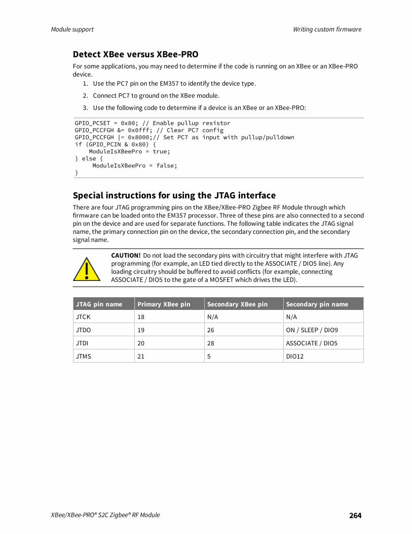
Module support Writing custom firmware
XBee/XBee-PRO® S2C Zigbee® RF Module 264
Detect XBee versus XBee-PROFor some applications, you may need to determine if the code is running on an XBee or an XBee-PROdevice.
1. Use the PC7 pin on the EM357 to identify the device type.
2. Connect PC7 to ground on the XBee module.
3. Use the following code to determine if a device is an XBee or an XBee-PRO:
GPIO_PCSET = 0x80; // Enable pullup resistorGPIO_PCCFGH &= 0x0fff; // Clear PC7 configGPIO_PCCFGH |= 0x8000;// Set PC7 as input with pullup/pulldownif (GPIO_PCIN & 0x80)
ModuleIsXBeePro = true; else
ModuleIsXBeePro = false;
Special instructions for using the JTAG interfaceThere are four JTAG programming pins on the XBee/XBee-PRO Zigbee RF Module through whichfirmware can be loaded onto the EM357 processor. Three of these pins are also connected to a secondpin on the device and are used for separate functions. The following table indicates the JTAG signalname, the primary connection pin on the device, the secondary connection pin, and the secondarysignal name.
CAUTION! Do not load the secondary pins with circuitry that might interfere with JTAGprogramming (for example, an LED tied directly to the ASSOCIATE / DIO5 line). Anyloading circuitry should be buffered to avoid conflicts (for example, connectingASSOCIATE / DIO5 to the gate of a MOSFET which drives the LED).
JTAG pin name Primary XBee pin Secondary XBee pin Secondary pin name
JTCK 18 N/A N/A
JTDO 19 26 ON / SLEEP / DIO9
JTDI 20 28 ASSOCIATE / DIO5
JTMS 21 5 DIO12

Regulatory information
United States (FCC) 266Europe (CE) 283IC (Industry Canada) 285Australia (RCM) 286ANATEL (Brazil) 287South Korea 290
XBee/XBee-PRO® S2C Zigbee® RF Module 265

Regulatory information United States (FCC)
XBee/XBee-PRO® S2C Zigbee® RF Module 266
United States (FCC)XBee/XBee-PRO Zigbee RF Modules comply with Part 15 of the FCC rules and regulations. Compliancewith the labeling requirements, FCC notices and antenna usage guidelines is required.To fulfill FCC Certification, the OEM must comply with the following regulations:
1. The system integrator must ensure that the text on the external label provided with thisdevice is placed on the outside of the final product.
2. RF Modules may only be used with antennas that have been tested and approved for use withthe modules.
OEM labeling requirements
WARNING! As an Original Equipment Manufacturer (OEM) you must ensure that FCClabeling requirements are met. You must include a clearly visible label on the outside ofthe final product enclosure that displays the following content:
Required FCC Label for OEM products containing the XBee S2D SMT RF ModuleContains FCC ID: MCQ-S2DSMThis device complies with Part 15 of the FCC Rules. Operation is subject to the following twoconditions: (1.) this device may not cause harmful interference and (2.) this device must accept anyinterference received, including interference that may cause undesired operation.
Required FCC Label for OEM products containing the XBee S2C SMT RF ModuleContains FCC ID: MCQ-XBS2CThis device complies with Part 15 of the FCC Rules. Operation is subject to the following twoconditions: (1.) this device may not cause harmful interference and (2.) this device must accept anyinterference received, including interference that may cause undesired operation.
Required FCC Label for OEM products containing the XBee-PRO S2C SMT RFModuleContains FCC ID: MCQ-PS2CSMThis device complies with Part 15 of the FCC Rules. Operation is subject to the following twoconditions: (1.) this device may not cause harmful interference and (2.) this device must accept anyinterference received, including interference that may cause undesired operation.
Note Legacy XBee-PRO SMT (Model: PRO S2C; hardware version 21xx) has FCC ID: MCQ-XBPS2C.
Required FCC Label for OEM products containing the XBee S2C TH RF ModuleContains FCC ID: MCQ-S2CTHThis device complies with Part 15 of the FCC Rules. Operation is subject to the following twoconditions: (1.) this device may not cause harmful interference and (2.) this device must accept anyinterference received, including interference that may cause undesired operation.
Required FCC Label for OEM products containing the XBee-PRO S2C TH RF ModuleContains FCC ID: MCQ-PS2CTH

Regulatory information United States (FCC)
XBee/XBee-PRO® S2C Zigbee® RF Module 267
This device complies with Part 15 of the FCC Rules. Operation is subject to the following twoconditions: (1.) this device may not cause harmful interference and (2.) this device must accept anyinterference received, including interference that may cause undesired operation.
FCC noticesIMPORTANT: XBee/XBee-PRO Zigbee RF Modules have been certified by the FCC for use with otherproducts without any further certification (as per FCC section 2.1091). Modifications not expresslyapproved by Digi could void the user's authority to operate the equipment.IMPORTANT: OEMs must test final product to comply with unintentional radiators (FCC section 15.107& 15.109) before declaring compliance of their final product to Part 15 of the FCC Rules.IMPORTANT: The RF module has been certified for remote and base radio applications. If the modulewill be used for portable applications, the device must undergo SAR testing.This equipment has been tested and found to comply with the limits for a Class B digital device,pursuant to Part 15 of the FCC Rules. These limits are designed to provide reasonable protectionagainst harmful interference in a residential installation. This equipment generates, uses and canradiate radio frequency energy and, if not installed and used in accordance with the instructions, maycause harmful interference to radio communications. However, there is no guarantee thatinterference will not occur in a particular installation.If this equipment does cause harmful interference to radio or television reception, which can bedetermined by turning the equipment off and on, the user is encouraged to try to correct theinterference by one or more of the following measures: Re-orient or relocate the receiving antenna,Increase the separation between the equipment and receiver, Connect equipment and receiver tooutlets on different circuits, or Consult the dealer or an experienced radio/TV technician for help.
FCC-approved antennas (2.4 GHz)The XBee/XBee-PRO Zigbee RF Module can be installed using antennas and cables constructed withnon-standard connectors (RPSMA, RPTNC, etc.) An adapter cable may be necessary to attach theXBee connector to the antenna connector.The modules are FCC approved for fixed base station andmobile applications for the channelsindicated in the tables below. If the antenna is mounted at least 25 cm (10 in) from nearby persons,the application is considered a mobile application. Antennas not listed in the table must be tested tocomply with FCC Section 15.203 (Unique Antenna Connectors) and Section 15.247 (Emissions).The antennas in the tables below have been approved for use with this module. Cable loss is requiredwhen using gain antennas as shown in the tables.Digi does not carry all of these antenna variants. Contact Digi Sales for available antennas.
1. If using the RF module in a portable application (for example, if the module is used in a hand-held device and the antenna is less than 25 cm from the human body when the device is inoperation), The integrator is responsible for passing additional Specific Absorption Rate (SAR)testing based on FCC rules 2.1091 and FCC Guidelines for Human Exposure to Radio FrequencyElectromagnetic Fields, OET Bulletin and Supplement C. The testing results will be submittedto the FCC for approval prior to selling the integrated unit. The required SAR testing measuresemissions from the module and how they affect the person.
2. Zigbee firmware will be limited to 32% duty cycle on channel 26.
3. If you are using 802.15.4 firmware with up to a 66% duty cycle on this channel.

Regulatoryinform
ationUnited
States(FCC)
XBee/XBee-PRO®S2CZigbee®RF
Module
268
XBee Zigbee SMT RF moduleThe following table shows the antennas approved for use with the XBee Zigbee SMT RF module.All antenna part numbers followed by an asterisk (*) are not available from Digi. Consult with an antenna manufacturer for an equivalent option.
Part numberType(description)
Gain(dBi) Application*
Min.separation
Minimum cable loss/powerreduction/attenuation required
Integral antennas
29000313 Integral PCB antenna 0.0 Fixed/Mobile 20 cm N/A N/A
A24-QI Monopole (Integrated whip) 1.5 Fixed/Mobile 20 cm N/A N/A
Dipole antennas
A24-HASM-450
Dipole (Half-wave articulated RPSMA - 4.5”) 2.1 Fixed 20 cm N/A N/A
A24-HABSM* Dipole (Articulated RPSMA) 2.1 Fixed 20 cm N/A N/A
29000095 Dipole (Half-wave articulated RPSMA - 4.5”) 2.1 Fixed/Mobile 20 cm N/A N/A
A24-HABUF-P5I
Dipole (Half-wave articulated bulkheadmountU.FL. w/ 5” pigtail)
2.1 Fixed/Mobile 20 cm N/A N/A
A24-HASM-525
Dipole (Half-wave articulated RPSMA - 5.25") 2.1 Fixed 20 cm N/A N/A
Omni-directional antennas
A24-F2NF Omni-directional (Fiberglass base station) 2.1 Fixed/Mobile 20 cm N/A N/A
A24-F3NF Omni-directional (Fiberglass base station) 3.0 Fixed/Mobile 20 cm N/A N/A
A24-F5NF Omni-directional (Fiberglass base station) 5.0 Fixed 20 cm N/A N/A
A24-F8NF Omni-directional (Fiberglass base station) 8.0 Fixed 2 m N/A N/A
A24-F9NF Omni-directional (Fiberglass base station) 9.5 Fixed 2 m N/A N/A

Regulatoryinform
ationUnited
States(FCC)
XBee/XBee-PRO®S2CZigbee®RF
Module
269
Part numberType(description)
Gain(dBi) Application*
Min.separation
Minimum cable loss/powerreduction/attenuation required
A24-F10NF Omni-directional (Fiberglass base station) 10.0 Fixed 2 m N/A N/A
A24-F12NF Omni-directional (Fiberglass base station) 12.0 Fixed 2 m N/A 2.0
A24-W7NF Omni-directional (Fiberglass base station) 7.2 Fixed 2 m N/A N/A
A24-M7NF Omni-directional (Mag-mount base station) 7.2 Fixed 2 m N/A N/A
A24-F15NF Omni-directional (Fiberglass base station) 15.0 Fixed 2 m N/A 5.0
Panel antennas
A24-P8SF Flat Panel 8.5 Fixed 2 m N/A 3.0
A24-P8NF Flat Panel 8.5 Fixed 2 m N/A 3.0
A24-P13NF Flat Panel 13.0 Fixed 2 m N/A 7.5
A24-P14NF Flat Panel 14.0 Fixed 2 m N/A 8.5
A24-P15NF Flat Panel 15.0 Fixed 2 m N/A 9.5
A24-P16NF Flat Panel 16.0 Fixed 2 m N/A 10.5
A24-P19NF Flat Panel 19.0 Fixed 2 m N/A 13.5
Yagi antennas
A24-Y6NF Yagi (6-element) 8.8 Fixed 2 m N/A 2.8
A24-Y7NF Yagi (7-element) 9.0 Fixed 2 m N/A 3.0
A24-Y9NF Yagi (9-element) 10.0 Fixed 2 m N/A 4.0
A24-Y10NF Yagi (10-element) 11.0 Fixed 2 m N/A 5.0
A24-Y12NF Yagi (12-element) 12.0 Fixed 2 m N/A 6.0
A24-Y13NF Yagi (13-element) 12.0 Fixed 2 m N/A 6.0

Regulatoryinform
ationUnited
States(FCC)
XBee/XBee-PRO®S2CZigbee®RF
Module
270
Part numberType(description)
Gain(dBi) Application*
Min.separation
Minimum cable loss/powerreduction/attenuation required
A24-Y15NF Yagi (15-element) 12.5 Fixed 2 m N/A 6.5
A24-Y16NF Yagi (16-element) 13.5 Fixed 2 m N/A 7.5
A24-Y16RM Yagi (16-element, RPSMA connector) 13.5 Fixed 2 m N/A 7.5
A24-Y18NF Yagi (18-element) 15.0 Fixed 2 m N/A 9.0

Regulatoryinform
ationUnited
States(FCC)
XBee/XBee-PRO®S2CZigbee®RF
Module
271
XBee Zigbee TH RF moduleThe following table shows the antennas approved for use with the XBee Zigbee TH RF Module.All antenna part numbers followed by an asterisk (*) are not available from Digi. Consult with an antenna manufacturer for an equivalent option.
Part number Type (description)Gain(dBi) Application*
Min.separation
Required antenna cable loss(dB)
Channels 11-25 Channel 26
Integral antennas
29000294 Integral PCB antenna -0.5 Fixed/Mobile 20 cm N/A N/A
A24-QI Monopole (Integrated whip) 1.5 Fixed/Mobile 20 cm N/A N/A
Dipole antennas
A24-HASM-450
Dipole (Half-wave articulated RPSMA - 4.5”) 2.1 Fixed 20 cm N/A N/A
A24-HABSM* Dipole (Articulated RPSMA) 2.1 Fixed 20 cm N/A N/A
29000095 Dipole (Half-wave articulated RPSMA - 4.5”) 2.1 Fixed/Mobile 20 cm N/A N/A
A24-HABUF-P5I
Dipole (Half-wave articulated bulkheadmount U.FL. w/ 5”pigtail)
2.1 Fixed/Mobile 20 cm N/A N/A
A24-HASM-525
Dipole (Half-wave articulated RPSMA - 5.25") 2.1 Fixed 20 cm N/A N/A
Omni-directional antennas
A24-F2NF Omni-directional (Fiberglass base station) 2.1 Fixed/Mobile 20 cm N/A N/A
A24-F3NF Omni-directional (Fiberglass base station) 3.0 Fixed/Mobile 20 cm N/A N/A
A24-F5NF Omni-directional (Fiberglass base station) 5.0 Fixed 20 cm N/A N/A

Regulatoryinform
ationUnited
States(FCC)
XBee/XBee-PRO®S2CZigbee®RF
Module
272
Part number Type (description)Gain(dBi) Application*
Min.separation
Required antenna cable loss(dB)
Channels 11-25 Channel 26
A24-F8NF Omni-directional (Fiberglass base station) 8.0 Fixed 2 m N/A 2.0
A24-F9NF Omni-directional (Fiberglass base station) 9.5 Fixed 2 m N/A 3.5
A24-F10NF Omni-directional (Fiberglass base station) 10.0 Fixed 2 m N/A 4.0
A24-F12NF Omni-directional (Fiberglass base station) 12.0 Fixed 2 m N/A 6.0
A24-W7NF Omni-directional (Fiberglass base station) 7.2 Fixed 2 m N/A 1.2
A24-M7NF Omni-directional (Mag-mount base station) 7.2 Fixed 2 m N/A 1.2
A24-F15NF Omni-directional (Fiberglass base station) 15.0 Fixed 2 m N/A 9.0
Panel antennas
A24-P8SF Flat Panel 8.5 Fixed 2 m N/A 2.5
A24-P8NF Flat Panel 8.5 Fixed 2 m N/A 2.5
A24-P13NF Flat Panel 13.0 Fixed 2 m N/A 7.0
A24-P14NF Flat Panel 14.0 Fixed 2 m N/A 8.0
A24-P15NF Flat Panel 15.0 Fixed 2 m N/A 9.0
A24-P16NF Flat Panel 16.0 Fixed 2 m N/A 10.0
A24-P19NF Flat Panel 19.0 Fixed 2 m N/A 13.0
Yagi antennas
A24-Y6NF Yagi (6-element) 8.8 Fixed 2 m N/A 2.8
A24-Y7NF Yagi (7-element) 9.0 Fixed 2 m N/A 3
A24-Y9NF Yagi (9-element) 10.0 Fixed 2 m N/A 4
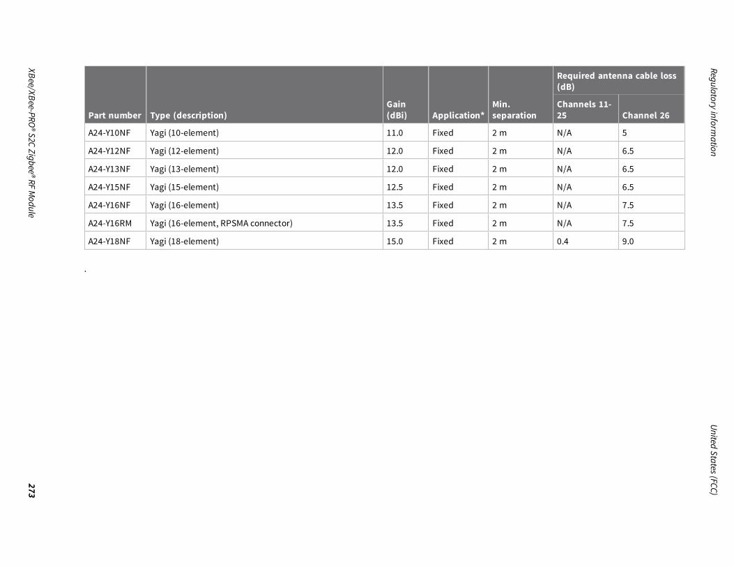
Regulatoryinform
ationUnited
States(FCC)
XBee/XBee-PRO®S2CZigbee®RF
Module
273
Part number Type (description)Gain(dBi) Application*
Min.separation
Required antenna cable loss(dB)
Channels 11-25 Channel 26
A24-Y10NF Yagi (10-element) 11.0 Fixed 2 m N/A 5
A24-Y12NF Yagi (12-element) 12.0 Fixed 2 m N/A 6.5
A24-Y13NF Yagi (13-element) 12.0 Fixed 2 m N/A 6.5
A24-Y15NF Yagi (15-element) 12.5 Fixed 2 m N/A 6.5
A24-Y16NF Yagi (16-element) 13.5 Fixed 2 m N/A 7.5
A24-Y16RM Yagi (16-element, RPSMA connector) 13.5 Fixed 2 m N/A 7.5
A24-Y18NF Yagi (18-element) 15.0 Fixed 2 m 0.4 9.0
.

Regulatoryinform
ationUnited
States(FCC)
XBee/XBee-PRO®S2CZigbee®RF
Module
274
XBee-PRO Zigbee SMT RF moduleThe following table shows the antennas approved for use with the XBee-PRO Zigbee SMT RF Module.All antenna part numbers followed by an asterisk (*) are not available from Digi. Consult with an antenna manufacturer for an equivalent option.
Part number Type (description)Gain(dBi) Application*
Minseparation
Required antenna cable loss(dB)
Channels 11-25 Channel 26
Internal antennas
29000313 Integral PCB antenna 0.0 Fixed/Mobile 20 cm N/A N/A
A24-QI Monopole (Integrated whip) 1.5 Fixed/Mobile 20 cm N/A N/A
Dipole antennas
A24-HASM-450
Dipole (Half-wave articulated RPSMA - 4.5”) 2.1 Fixed 20 cm N/A N/A
A24-HABSM* Dipole (Articulated RPSMA) 2.1 Fixed 20 cm N/A N/A
29000095 Dipole (Half-wave articulated RPSMA - 4.5”) 2.1 Fixed/Mobile 20 cm N/A N/A
A24-HABUF-P5I
Dipole (Half-wave articulated bulkheadmount U.FL. w/ 5”pigtail)
2.1 Fixed/Mobile 20 cm N/A N/A
A24-HASM-525
Dipole (Half-wave articulated RPSMA - 5.25") 2.1 Fixed 20 cm N/A N/A
Omni-directional antennas
A24-F2NF Omni-directional (Fiberglass base station) 2.1 Fixed/Mobile 20 cm N/A N/A
A24-F3NF Omni-directional (Fiberglass base station) 3.0 Fixed/Mobile 20 cm N/A N/A
A24-F5NF Omni-directional (Fiberglass base station) 5.0 Fixed 20 cm N/A N/A

Regulatoryinform
ationUnited
States(FCC)
XBee/XBee-PRO®S2CZigbee®RF
Module
275
Part number Type (description)Gain(dBi) Application*
Minseparation
Required antenna cable loss(dB)
Channels 11-25 Channel 26
A24-F8NF Omni-directional (Fiberglass base station) 8.0 Fixed 2 m N/A 1.3
A24-F9NF Omni-directional (Fiberglass base station) 9.5 Fixed 2 m N/A 2.8
A24-F10NF Omni-directional (Fiberglass base station) 10 Fixed 2 m N/A 3.3
A24-F12NF Omni-directional (Fiberglass base station) 12 Fixed 2 m N/A 5.3
A24-W7NF Omni-directional (Fiberglass base station) 7.2 Fixed 2 m N/A .5
A24-M7NF Omni-directional (Mag-mount base station) 7.2 Fixed 2 m N/A .5
A24-F15NF Omni-directional (Fiberglass base station) 15.0 Fixed 2 m 1.1 8.3
Panel antennas
A24-P8SF Flat Panel 8.5 Fixed 2 m 2.8 4.5
A24-P8NF Flat Panel 8.5 Fixed 2 m 2.8 4.5
A24-P13NF Flat Panel 13.0 Fixed 2 m 7.3 9.0
A24-P14NF Flat Panel 14.0 Fixed 2 m 8.3 10.0
A24-P15NF Flat Panel 15.0 Fixed 2 m 9.3 11.0
A24-P16NF Flat Panel 16.0 Fixed 2 m 10.3 12.0
A24-P19NF Flat Panel 19.0 Fixed 2 m 13.3 15.0
Yagi antennas
A24-Y6NF Yagi (6-element) 8.8 Fixed 2 m 2.4 4.2
A24-Y7NF Yagi (7-element) 9.0 Fixed 2 m 2.6 4.4
A24-Y9NF Yagi (9-element) 10.0 Fixed 2 m 3.6 5.4

Regulatoryinform
ationUnited
States(FCC)
XBee/XBee-PRO®S2CZigbee®RF
Module
276
Part number Type (description)Gain(dBi) Application*
Minseparation
Required antenna cable loss(dB)
Channels 11-25 Channel 26
A24-Y10NF Yagi (10-element) 11.0 Fixed 2 m 4.6 6.4
A24-Y12NF Yagi (12-element) 12.0 Fixed 2 m 5.6 7.4
A24-Y13NF Yagi (13-element) 12.0 Fixed 2 m 5.6 7.4
A24-Y15NF Yagi (15-element) 12.5 Fixed 2 m 6.1 7.9
A24-Y16NF Yagi (16-element) 13.5 Fixed 2 m 7.1 8.9
A24-Y16RM Yagi (16-element, RPSMA connector) 13.5 Fixed 2 m 7.1 8.9
A24-Y18NF Yagi (18-element) 15.0 Fixed 2 m 8.6 10.4
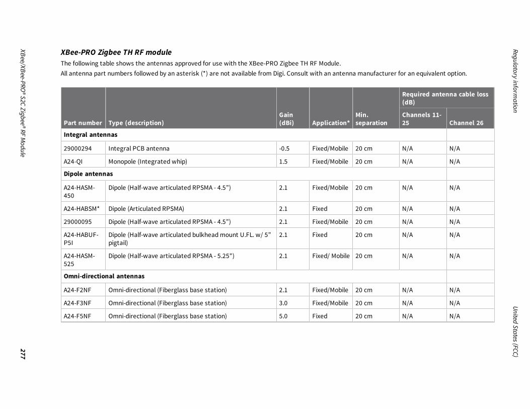
Regulatoryinform
ationUnited
States(FCC)
XBee/XBee-PRO®S2CZigbee®RF
Module
277
XBee-PRO Zigbee TH RF moduleThe following table shows the antennas approved for use with the XBee-PRO Zigbee TH RF Module.All antenna part numbers followed by an asterisk (*) are not available from Digi. Consult with an antenna manufacturer for an equivalent option.
Part number Type (description)Gain(dBi) Application*
Min.separation
Required antenna cable loss(dB)
Channels 11-25 Channel 26
Integral antennas
29000294 Integral PCB antenna -0.5 Fixed/Mobile 20 cm N/A N/A
A24-QI Monopole (Integrated whip) 1.5 Fixed/Mobile 20 cm N/A N/A
Dipole antennas
A24-HASM-450
Dipole (Half-wave articulated RPSMA - 4.5”) 2.1 Fixed/Mobile 20 cm N/A N/A
A24-HABSM* Dipole (Articulated RPSMA) 2.1 Fixed 20 cm N/A N/A
29000095 Dipole (Half-wave articulated RPSMA - 4.5”) 2.1 Fixed/Mobile 20 cm N/A N/A
A24-HABUF-P5I
Dipole (Half-wave articulated bulkheadmount U.FL. w/ 5”pigtail)
2.1 Fixed 20 cm N/A N/A
A24-HASM-525
Dipole (Half-wave articulated RPSMA - 5.25") 2.1 Fixed/ Mobile 20 cm N/A N/A
Omni-directional antennas
A24-F2NF Omni-directional (Fiberglass base station) 2.1 Fixed/Mobile 20 cm N/A N/A
A24-F3NF Omni-directional (Fiberglass base station) 3.0 Fixed/Mobile 20 cm N/A N/A
A24-F5NF Omni-directional (Fiberglass base station) 5.0 Fixed 20 cm N/A N/A

Regulatoryinform
ationUnited
States(FCC)
XBee/XBee-PRO®S2CZigbee®RF
Module
278
Part number Type (description)Gain(dBi) Application*
Min.separation
Required antenna cable loss(dB)
Channels 11-25 Channel 26
A24-F8NF Omni-directional (Fiberglass base station) 8.0 Fixed 2 m N/A N/A
A24-F9NF Omni-directional (Fiberglass base station) 9.5 Fixed 2 m N/A N/A
A24-F10NF Omni-directional (Fiberglass base station) 10.0 Fixed 2 m N/A N/A
A24-F12NF Omni-directional (Fiberglass base station) 12.0 Fixed 2 m N/A .9
A24-W7NF Omni-directional (base station) 7.2 Fixed 2 m N/A N/A
A24-M7NF Omni-directional (Mag-mount base station) 7.2 Fixed 2 m N/A N/A
A24-F15NF Omni-directional (Fiberglass base station) 15.0 Fixed 2 m 2.5 3.9
Panel antennas
A24-P8SF Flat Panel 8.5 Fixed 2 m 1 1.6
A24-P8NF Flat Panel 8.5 Fixed 2 m 1 1.6
A24-P13NF Flat Panel 13 Fixed 2 m 5.5 6.1
A24-P14NF Flat Panel 14 Fixed 2 m 6.5 7.1
A24-P15NF Flat Panel 15.0 Fixed 2 m 7.5 8.1
A24-P16NF Flat Panel 16.0 Fixed 2 m 8.5 9.1
A24-19NF Flat Panel 19.0 Fixed 2 m 11.5 12.1
Yagi antennas
A24-Y6NF Yagi (6-element) 8.8 Fixed 2 m .3 N/A
A24-Y7NF Yagi (7-element) 9.0 Fixed 2 m .5 N/A
A24-Y9NF Yagi (9-element) 10.0 Fixed 2 m 1.5 1.0

Regulatoryinform
ationUnited
States(FCC)
XBee/XBee-PRO®S2CZigbee®RF
Module
279
Part number Type (description)Gain(dBi) Application*
Min.separation
Required antenna cable loss(dB)
Channels 11-25 Channel 26
A24-Y10NF Yagi (10-element) 11.0 dBi Fixed 2 m 2.5 2.0
A24-Y12NF Yagi (12-element) 12.0 Fixed 2 m 3.5 3.0
A24-Y13NF Yagi (13-element) 12.0 Fixed 2 m 3.5 3.0
A24-Y15NF Yagi (15-element) 12.5 Fixed 2 m 4.0 3.5
A24-Y16NF Yagi (16-element) 13.5 Fixed 2 m 5.0 4.5
A24-Y16RM Yagi (16-element, RPSMA connector) 13.5 Fixed 2 m 5.0 4.5
A24-Y18NF Yagi (18-element) 15.0 Fixed 2 m 6.5 6.0

Regulatoryinform
ationUnited
States(FCC)
XBee/XBee-PRO®S2CZigbee®RF
Module
280
XBee S2D SMT moduleThe following table shows the antennas approved for use with the XBee S2D SMT surface-mount module. See Associated antenna descriptions foradditional cable loss required beyond the antennas listed below.All antenna part numbers followed by an asterisk (*) are not available from Digi. Consult with an antenna manufacturer for an equivalent option.
Part number Type (description)Gain(dBi)
Application1
Min.separation
Required cable-loss orpower reduction from+8 dBm channels 11 to24
Required cable-lossor power reductionfrom +8 dBmchannel 25
Required cable-lossor power reductionfrom +1 dBm channel26
Yagi Class Antennas
A24-Y6NF Yagi (6-element) 8.8 Fixed 20 cm 0 0 5
A24-Y7NF Yagi (7-element) 9.0 Fixed 20 cm 0 0 5
A24-Y9NF Yagi (9-element) 10.0 Fixed 20 cm 0 0 6
A24-Y10NF Yagi (10-element) 11.0 Fixed 20 cm 0 1 7
A24-Y12NF Yagi (12-element) 12.0 Fixed 20 cm 0 2 8
A24-Y13NF Yagi (13-element) 12.0 Fixed 20 cm 0 2 8
A24-Y15NF Yagi (15-element) 12.5 Fixed 20 cm 0 2.5 8.5
A24-Y16NF Yagi (16-element) 13.5 Fixed 20 cm 0 3.5 9.5
A24-Y16RM Yagi (16-element,RPSMA connector)
13.5 Fixed 20 cm 0 3.5 9.5
A24-Y18NF Yagi (18-element) 15.0 Fixed 20 cm 0 5 11
Omni-directional antennas
A24-F2NF Omni-directional(Fiberglass basestation)
2.1 Fixed/Mobile 20 cm 0 0 0

Regulatoryinform
ationUnited
States(FCC)
XBee/XBee-PRO®S2CZigbee®RF
Module
281
Part number Type (description)Gain(dBi)
Application1
Min.separation
Required cable-loss orpower reduction from+8 dBm channels 11 to24
Required cable-lossor power reductionfrom +8 dBmchannel 25
Required cable-lossor power reductionfrom +1 dBm channel26
A24-F3NF Omni-directional(Fiberglass basestation)
3.0 Fixed/Mobile 20 cm 0 0 0
A24-F5NF Omni-directional(Fiberglass basestation)
5.0 Fixed/Mobile 20 cm 0 0 0
A24-F8NF Omni-directional(Fiberglass basestation)
8.0 Fixed 20 cm 0 0 0
A24-F9NF Omni-directional(Fiberglass basestation)
9.5 Fixed 20 cm 0 0 1.5
A24-F10NF Omni-directional(Fiberglass basestation)
10.0 Fixed 20 cm 0 0 2.5
A24-F12NF Omni-directional(Fiberglass basestation)
12.0 Fixed 20 cm 0 0 4.5
A24-F15NF Omni-directional(Fiberglass basestation)
15.0 Fixed 20 cm 0 0 7.5
A24-W7NF Omni-directional (Basestation)
7.2 Fixed 20 cm 0 0 0
A24-M7NF Omni-directional (Mag-mount base station)
7.2 Fixed 20 cm 0 0 0

Regulatoryinform
ationUnited
States(FCC)
XBee/XBee-PRO®S2CZigbee®RF
Module
282
Part number Type (description)Gain(dBi)
Application1
Min.separation
Required cable-loss orpower reduction from+8 dBm channels 11 to24
Required cable-lossor power reductionfrom +8 dBmchannel 25
Required cable-lossor power reductionfrom +1 dBm channel26
Dipole Antennas
A24-HASM-450
Dipole (Half-wavearticulated RPSMA -4.5”)
2.1 Fixed/Mobile 20 cm 0 0 0
A24-HABSM* Dipole (ArticulatedRPSMA)
2.1 Fixed 20 cm 0 0 0
A24-HABUF-P5I
Dipole (Half-wavearticulated bulkheadmount U.FL. w/ 5”pigtail)
2.1 Fixed 20 cm 0 0 0
A24-HASM-525
Dipole (Half-wavearticulated RPSMA -5.25")
2.1 Fixed 20 cm 0 0 0
Panel class antennas
A24-P8SF Flat Panel 8.5 Fixed 20 cm 0 0 5.5
A24-P8NF Flat Panel 8.5 Fixed 20 cm 0 0 5.5
A24-P13NF Flat Panel 13.0 Fixed 20 cm 0 2 10
A24-P14NF Flat Panel 14.0 Fixed 20 cm 0 3 11
A24-P15NF Flat Panel 15.0 Fixed 20 cm 0 4 12
A24-P16NF Flat Panel 16.0 Fixed 20 cm 0 5 13
A24-P19NF Flat Panel 19.0 Fixed 20 cm 0 8 16
Integral antennas
29000313 Integral PCB antenna 0.0 Fixed 20 cm 0 0 0

Regulatory information Europe (CE)
XBee/XBee-PRO® S2C Zigbee® RF Module 283
Associated antenna descriptionsThe following table shows the associated antenna descriptions.
Antenna typeMaximum gainallowed
Required minimum assembly and cable loss formaximum gain of antenna
Integral PCB 0.0 dBi 0.0 dB
Dipole 2.1 dBi 0.63 dB
Omni-directional 15.0 dBi 1.25 dB
Yagi 15.0 dBi 1.25 dB
Flat panel 19.0 dBi 1.25 dB
RF exposureIf you are an integrating the XBee into another product, you must include the following Cautionstatement in OEM product manuals to alert users of FCC RF exposure compliance:
CAUTION! To satisfy FCC RF exposure requirements for mobile transmitting devices, aseparation distance of 20 cm or more should be maintained between the antenna of thisdevice and persons during device operation. To ensure compliance, operations at closerthan this distance are not recommended. The antenna used for this transmitter mustnot be co-located in conjunction with any other antenna or transmitter.
Europe (CE)The XBee ZigBee RF Modules (non-PRO variants) have been tested for use in several Europeancountries. For a complete list, refer to www.digi.com/resources/certifications.If XBee ZigBee RF Modules are incorporated into a product, the manufacturer must ensurecompliance of the final product with articles 3.1a and 3.1b of the Radio Equipment Directive. ADeclaration of Conformity must be issued for each of these standards and kept on file as described inthe Radio Equipment Directive.Furthermore, the manufacturer must maintain a copy of the XBee ZigBee RF Modules user guidedocumentation and ensure the final product does not exceed the specified power ratings, antennaspecifications, and/or installation requirements as specified in the user guide.
Maximum power and frequency specificationsFor the S2C through-hole device:
n Maximum power: 9.82 mW (9.92 dBm) Equivalent Isotropically Radiated Power (EIRP) at normalcondition.
n Frequencies: 5 MHz channel spacing, beginning at 2405 MHz and ending at 2480 MHz.
For the S2C surface-mount device:n Maximum power: 12.65 mW (11.02 dBm) EIRP.
n Frequencies: 5 MHz channel spacing, beginning at 2405 MHz and ending at 2480 MHz.
For the S2D surface-mount device:

Regulatory information Europe (CE)
XBee/XBee-PRO® S2C Zigbee® RF Module 284
n Maximum power: 9.91 mW (9.96 dBm) EIRP.
n Frequencies: 5 MHz channel spacing, beginning at 2405 MHz and ending at 2480 MHz.
OEM labeling requirementsThe “CE” marking must be affixed to a visible location on the OEM product. The following figure showsCE labeling requirements.
The CE mark shall consist of the initials “CE” taking the following form:n If the CE marking is reduced or enlarged, the proportions given in the above graduated
drawing must be respected.
n The CE marking must have a height of at least 5 mm except where this is not possible onaccount of the nature of the apparatus.
n The CE marking must be affixed visibly, legibly, and indelibly.
Important noteDigi customers assume full responsibility for learning andmeeting the required guidelines for eachcountry in their distribution market. Refer to the radio regulatory agency in the desired countries ofoperation for more information.
Declarations of conformityDigi has issued Declarations of Conformity for the XBee RF Modules concerning emissions, EMC, andsafety. For more information, see www.digi.com/resources/certifications.
AntennasThe following antennas have been tested and approved for use with the XBee/XBee-PRO Zigbee RFModule:All antenna part numbers followed by an asterisk (*) are not available from Digi. Consult with anantenna manufacturer for an equivalent option.

Regulatory information IC (Industry Canada)
XBee/XBee-PRO® S2C Zigbee® RF Module 285
n Dipole (2.1 dBi, Omni-directional, Articulated RPSMA, Digi part number A24-HABSM)
n PCB Antenna (0.0 dBi)
n Monopole Whip (1.5 dBi)
IC (Industry Canada)
Labeling requirementsLabeling requirements for Industry Canada are similar to those of the FCC. A clearly visible label onthe outside of the final product enclosure must display the following text.
For XBee ZB surface-mount:Contains Model XBee S2C Radio, IC: 1846A-XBS2CThe integrator is responsible for its product to comply with IC ICES-003 & FCC Part 15, Sub. B -Unintentional Radiators. ICES-003 is the same as FCC Part 15 Sub. B and Industry Canada acceptsFCC test report or CISPR 22 test report for compliance with ICES-003.
For XBee-PRO ZB surface-mount:Contains Model PS2CSM Radio, IC: 1846A-PS2CSMThe integrator is responsible for its product to comply with IC ICES-003 & FCC Part 15, Sub. B -Unintentional Radiators. ICES-003 is the same as FCC Part 15 Sub. B and Industry Canada acceptsFCC test report or CISPR 22 test report for compliance with ICES-003.
Note Legacy XBee-PRO SMT (Model: PRO S2C; hardware version 21xx) has IC: 1846A-XBPS2C.
For XBee ZB through-hole:Contains Model S2CTH Radio, IC: 1846A-S2CTHThe integrator is responsible for its product to comply with IC ICES-003 & FCC Part 15, Sub. B -Unintentional Radiators. ICES-003 is the same as FCC Part 15 Sub. B and Industry Canada acceptsFCC test report or CISPR 22 test report for compliance with ICES-003.
For XBee-PRO ZB through-hole:Contains Model PS2CTH Radio, IC: 1846A-PS2CTHThe integrator is responsible for its product to comply with IC ICES-003 & FCC Part 15, Sub. B -Unintentional Radiators. ICES-003 is the same as FCC Part 15 Sub. B and Industry Canada acceptsFCC test report or CISPR 22 test report for compliance with ICES-003.
Transmitters for detachable antennasThis device has been designed to operate with the antennas listed in the previous table and having amaximum of 19 dB. Antennas not included in this list or having a gain greater than 19 dB are strictlyprohibited for use with this device. The required antenna impedance is 50 ohms.
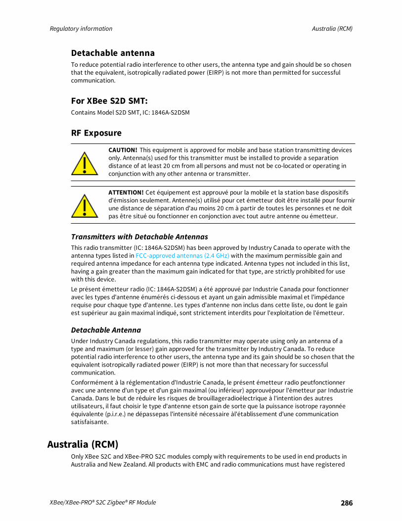
Regulatory information Australia (RCM)
XBee/XBee-PRO® S2C Zigbee® RF Module 286
Detachable antennaTo reduce potential radio interference to other users, the antenna type and gain should be so chosenthat the equivalent, isotropically radiated power (EIRP) is not more than permitted for successfulcommunication.
For XBee S2D SMT:Contains Model S2D SMT, IC: 1846A-S2DSM
RF Exposure
CAUTION! This equipment is approved for mobile and base station transmitting devicesonly. Antenna(s) used for this transmitter must be installed to provide a separationdistance of at least 20 cm from all persons andmust not be co-located or operating inconjunction with any other antenna or transmitter.
ATTENTION! Cet équipement est approuvé pour la mobile et la station base dispositifsd'émission seulement. Antenne(s) utilisé pour cet émetteur doit être installé pour fournirune distance de séparation d'au moins 20 cm à partir de toutes les personnes et ne doitpas être situé ou fonctionner en conjonction avec tout autre antenne ou émetteur.
Transmitters with Detachable AntennasThis radio transmitter (IC: 1846A-S2DSM) has been approved by Industry Canada to operate with theantenna types listed in FCC-approved antennas (2.4 GHz) with the maximum permissible gain andrequired antenna impedance for each antenna type indicated. Antenna types not included in this list,having a gain greater than the maximum gain indicated for that type, are strictly prohibited for usewith this device.Le présent émetteur radio (IC: 1846A-S2DSM) a été approuvé par Industrie Canada pour fonctionneravec les types d'antenne énumérés ci-dessous et ayant un gain admissible maximal et l'impédancerequise pour chaque type d'antenne. Les types d'antenne non inclus dans cette liste, ou dont le gainest supérieur au gain maximal indiqué, sont strictement interdits pour l'exploitation de l'émetteur.
Detachable AntennaUnder Industry Canada regulations, this radio transmitter may operate using only an antenna of atype andmaximum (or lesser) gain approved for the transmitter by Industry Canada. To reducepotential radio interference to other users, the antenna type and its gain should be so chosen that theequivalent isotropically radiated power (EIRP) is not more than that necessary for successfulcommunication.Conformément à la réglementation d'Industrie Canada, le présent émetteur radio peutfonctionneravec une antenne d'un type et d'un gain maximal (ou inférieur) approuvépour l'émetteur par IndustrieCanada. Dans le but de réduire les risques de brouillageradioélectrique à l'intention des autresutilisateurs, il faut choisir le type d'antenne etson gain de sorte que la puissance isotrope rayonnéeéquivalente (p.i.r.e.) ne dépassepas l'intensité nécessaire àl'établissement d'une communicationsatisfaisante.
Australia (RCM)Only XBee S2C and XBee-PRO S2C modules comply with requirements to be used in end products inAustralia and New Zealand. All products with EMC and radio communications must have registered

Regulatory information ANATEL (Brazil)
XBee/XBee-PRO® S2C Zigbee® RF Module 287
RCM and R-NZ marks. Registration to use the compliance mark will only be accepted from Australia orNew Zealandmanufacturers or importers, or their agents.In order to have a RCM or R-NZ mark on an end product, a company must comply with a or b below.
a. have a company presence in Australia or New Zealand.
b. have a company/distributor/agent in Australia or New Zealand that will sponsor the importingof the end product.
Contact Digi for questions related to locating a contact in Australia and New Zealand.
ANATEL (Brazil)The XBee ZB RF devices comply with Brazil ANATEL standards in Resolution No. 506. The followinginformation is required in the user manual for the product containing the radio and on the productcontaining the radio (in Portuguese):Digi Model: XB24CZ7PIS-004, XB24CZ7PISB003, XB24CZ7RIS-004, XB24CZ7RISB003, XB24CZ7UIS-004e XB24CZ7UISB003

Regulatory information ANATEL (Brazil)
XBee/XBee-PRO® S2C Zigbee® RF Module 288

Regulatory information ANATEL (Brazil)
XBee/XBee-PRO® S2C Zigbee® RF Module 289

Regulatory information South Korea
XBee/XBee-PRO® S2C Zigbee® RF Module 290
South KoreaThe low-power XBee S2C TH and XBee S2C devices have received South Korean approvals. To showconformity to the certificate, you must add a label with the South Korean product information to theXBee S2C Zigbee RF Module.For the through-hole device, you can place the label on the reverse side.Recommended label material: Abraham Technical (700342) MFG P/N TAAE-014250.The label size is: 15.9 mm x 15.9 mm (0.625 in x 0.625 in)The complete label information is as follows:
The KCC logo must be at least 5 mm tall.The text shown in the label is:
1. : XBee S2C TH
2. : MSIP-CRM-DIG-XBee-S2C-TH
3. : DIGI INTERNATIONAL, INC.
4. / : DIGI INTERNATIONAL, INC. /
If the label size does not accommodate the required content, you can use abbreviated information, asfollows:
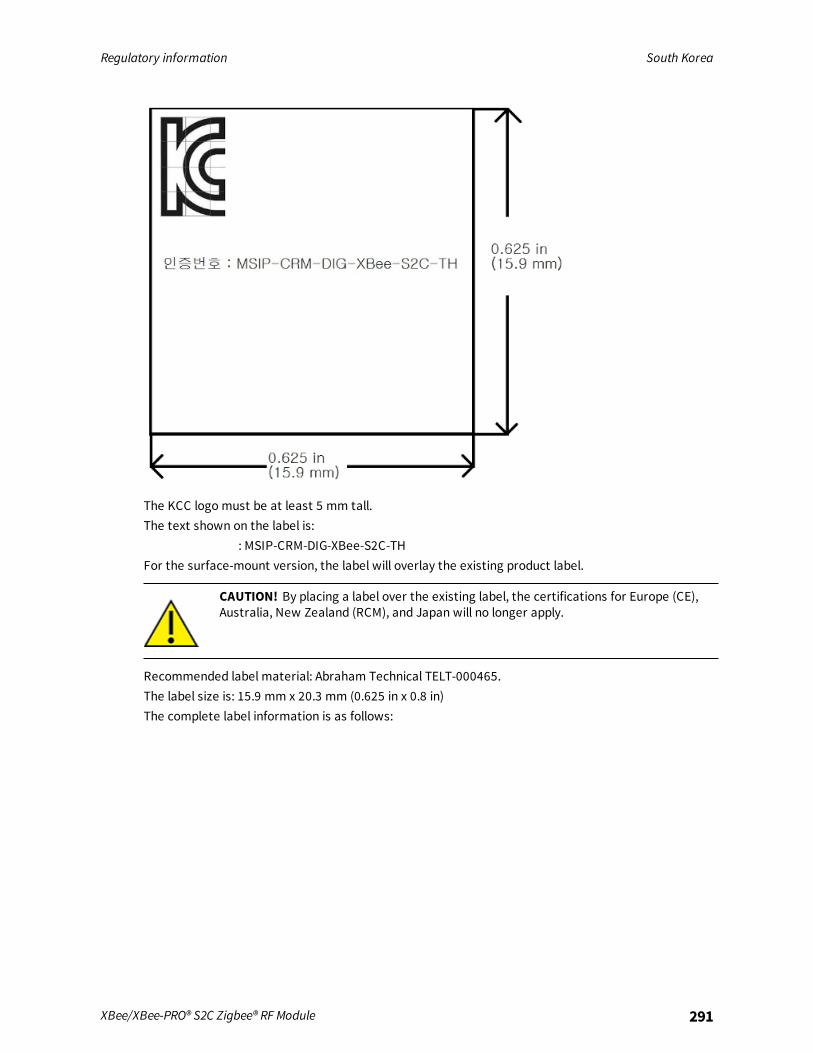
Regulatory information South Korea
XBee/XBee-PRO® S2C Zigbee® RF Module 291
The KCC logo must be at least 5 mm tall.The text shown on the label is:
: MSIP-CRM-DIG-XBee-S2C-THFor the surface-mount version, the label will overlay the existing product label.
CAUTION! By placing a label over the existing label, the certifications for Europe (CE),Australia, New Zealand (RCM), and Japan will no longer apply.
Recommended label material: Abraham Technical TELT-000465.The label size is: 15.9 mm x 20.3 mm (0.625 in x 0.8 in)The complete label information is as follows:

Regulatory information South Korea
XBee/XBee-PRO® S2C Zigbee® RF Module 292
The KCC logo must be at least 5 mm tall.The text shown in the label is:
1. : XBee S2C
2. : MSIP-CRM-DIG-XBee-S2C
3. : DIGI INTERNATIONAL, INC.
4. / : DIGI INTERNATIONAL, INC. /
If the label size does not accommodate the required content, you can use the abbreviatedinformation, as follows:

Regulatory information South Korea
XBee/XBee-PRO® S2C Zigbee® RF Module 293
The KCC logo must be at least 5 mm tall.The text shown in the label is:
: MSIP-CRM-DIG-XBee-S2C

Migrating from XBee through-hole to XBee surface-mount devices
The XBee surface-mount and through-hole devices are designed to be compatible and offer the samebasic feature set. As mentioned previously, the surface-mount form factor has more I/O pins.This section provides information to help users migrate from the surface-mount to the Through-holeform factor.
Pin mapping 295Mounting 296
XBee/XBee-PRO® S2C Zigbee® RF Module 294
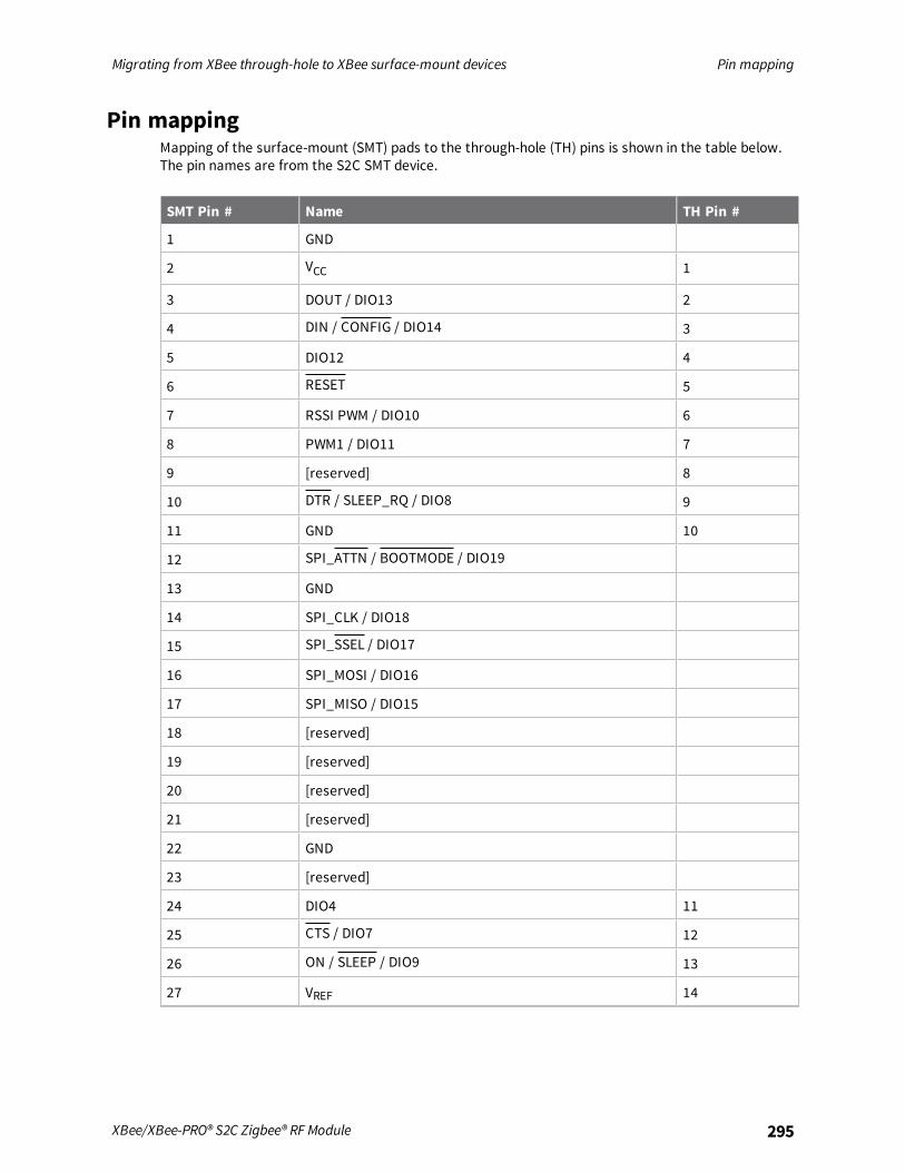
Migrating from XBee through-hole to XBee surface-mount devices Pin mapping
XBee/XBee-PRO® S2C Zigbee® RF Module 295
Pin mappingMapping of the surface-mount (SMT) pads to the through-hole (TH) pins is shown in the table below.The pin names are from the S2C SMT device.
SMT Pin # Name TH Pin #
1 GND
2 VCC 1
3 DOUT / DIO13 2
4 DIN / CONFIG / DIO14 3
5 DIO12 4
6 RESET 5
7 RSSI PWM / DIO10 6
8 PWM1 / DIO11 7
9 [reserved] 8
10 DTR / SLEEP_RQ / DIO8 9
11 GND 10
12 SPI_ATTN / BOOTMODE / DIO19
13 GND
14 SPI_CLK / DIO18
15 SPI_SSEL / DIO17
16 SPI_MOSI / DIO16
17 SPI_MISO / DIO15
18 [reserved]
19 [reserved]
20 [reserved]
21 [reserved]
22 GND
23 [reserved]
24 DIO4 11
25 CTS / DIO7 12
26 ON / SLEEP / DIO9 13
27 VREF 14
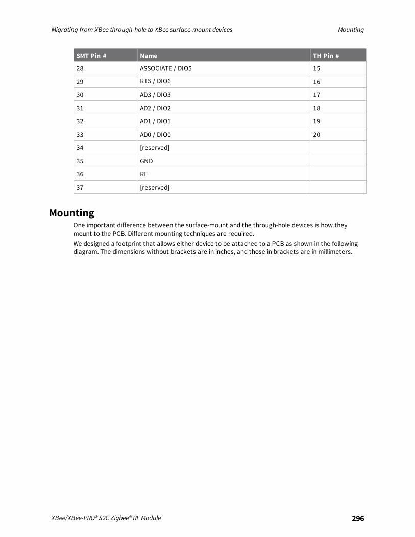
Migrating from XBee through-hole to XBee surface-mount devices Mounting
XBee/XBee-PRO® S2C Zigbee® RF Module 296
SMT Pin # Name TH Pin #
28 ASSOCIATE / DIO5 15
29 RTS / DIO6 16
30 AD3 / DIO3 17
31 AD2 / DIO2 18
32 AD1 / DIO1 19
33 AD0 / DIO0 20
34 [reserved]
35 GND
36 RF
37 [reserved]
MountingOne important difference between the surface-mount and the through-hole devices is how theymount to the PCB. Different mounting techniques are required.We designed a footprint that allows either device to be attached to a PCB as shown in the followingdiagram. The dimensions without brackets are in inches, and those in brackets are in millimeters.

Migrating from XBee through-hole to XBee surface-mount devices Mounting
XBee/XBee-PRO® S2C Zigbee® RF Module 297
The round holes in the diagram are for the through-hole design, and the semi-oval pads are for thesurface-mount design. Pin 1 of the through-hole design lines up with pad 1 of the surface-mountdesign, but the pins are actually offset by one pad (see Pin mapping). By using diagonal traces toconnect the appropriate pins, the layout works for both modules.For information on attaching the SMT device, see Manufacturing information.
Manufacturing information
XBee/XBee-PRO® S2C Zigbee® RF Module 298
Manufacturing information
The XBee/XBee-PRO Zigbee RF Module is designed for surface-mounting on the OEM PCB. It hascastellated pads to allow for easy solder attaching and inspection. The pads are all located on theedge of the device so there are no hidden solder joints on these devices.
Recommended solder reflow cycle 299Recommended footprint 299Flux and cleaning 300Reworking 300

Manufacturing information Recommended solder reflow cycle
XBee/XBee-PRO® S2C Zigbee® RF Module 299
Recommended solder reflow cycleThe following table lists the recommended solder reflow cycle. The chart shows the temperaturesetting and the time to reach the temperature.
Time (seconds) Temperature (°C)
30 65
60 100
90 135
120 160
150 195
180 240
210 260
The maximum temperature should not exceed 260 °C.The device reflows during this cycle, andmust not be reflowed upside down. Be careful not to jar thedevice while the solder is molten, as parts inside the device can be removed from their requiredlocations.Hand soldering is possible and should be done in accordance with approved standards.The XBee/XBee-PRO Zigbee RF Modules are level 3 Moisture Sensitive Devices. When using this kind ofdevice, consider the relative requirements in accordance with standard IPC/JEDEC J-STD-020.In addition, note the following conditions:
a. Calculated shelf life in sealed bag: 12 months at <40 °C and <90% relative humidity (RH).
b. Environmental condition during the production: 30 °C /60% RH according to IPC/JEDEC J-STD -033C, paragraphs 5 through 7.
c. The time between the opening of the sealed bag and the start of the reflow process cannotexceed 168 hours if condition b) is met.
d. Baking is required if conditions b) or c) are not met.
e. Baking is required if the humidity indicator inside the bag indicates a RH of 10% more.
f. If baking is required, bake modules in trays stacked no more than 10 high for 4-6 hours at 125°C.
Recommended footprintWe recommend that you use the following PCB footprints for surface-mounting. The dimensionswithout brackets are in inches, and those in brackets are in millimeters.Match the solder footprint to the copper pads, but may need to be adjusted depending on the specificneeds of assembly and product standards. Recommended stencil thickness is 0.15 mm/0.005”. Placethe component last and set the placement speed to the slowest setting.While the underside of the device is mostly coated with solder resist, we recommended the copperlayer directly below the device be left open to avoid unintended contacts. Copper or vias must notinterfere with the three exposed RF test points on the bottom of the device as shown in the following
Manufacturing information Flux and cleaning
XBee/XBee-PRO® S2C Zigbee® RF Module 300
diagram. These devices have a ground plane in the middle on the back side for shielding purposes,which can be affected by copper traces directly below the device.
Flux and cleaningDigi recommends that a “no clean” solder paste be used in assembling these devices. This eliminatesthe clean step and ensures unwanted residual flux is not left under the device where it is difficult toremove.In addition the following issues can occur:
n Cleaning with liquids can result in liquid remaining under the shield or in the gap between thedevice and the OEM PCB. This can lead to unintended connections between pads on the device.
n The residual moisture and flux residue under the device are not easily seen during aninspection process.
Factory recommended best practice is to use a “no clean” solder paste to avoid these issues andensure proper device operation.
ReworkingNever perform rework on the device itself. The device has been optimized to give the best possibleperformance, and reworking the device itself will void warranty coverage and certifications. Werecognize that some customers choose to rework and void the warranty. The following informationserves as a guideline in such cases to increase the chances of success during rework, though thewarranty is still voided.The device may be removed from the OEM PCB by the use of a hot air rework station, or hot plate. Becareful not to overheat the device. During rework, the device temperature may rise above its internalsolder melting point and care should be taken not to dislodge internal components from theirintended positions.

Load Zigbee firmware on 802.15.4 devices
Background 302Load Zigbee firmware 303
XBee/XBee-PRO® S2C Zigbee® RF Module 301
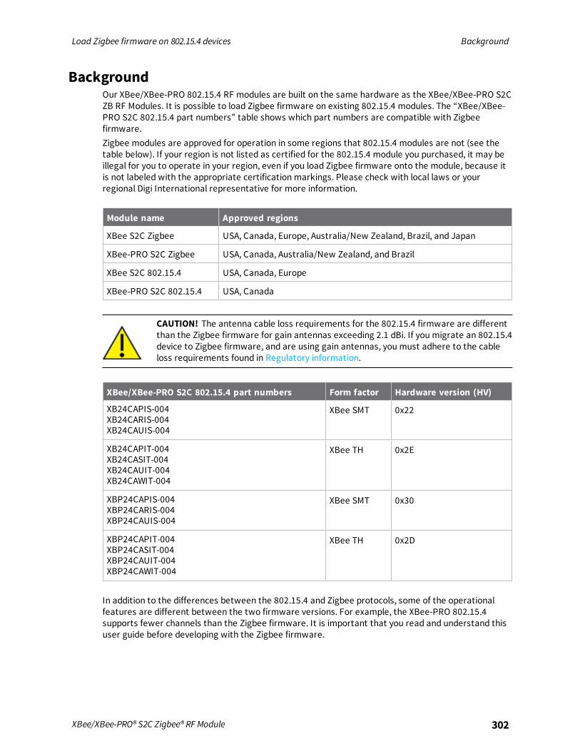
Load Zigbee firmware on 802.15.4 devices Background
XBee/XBee-PRO® S2C Zigbee® RF Module 302
BackgroundOur XBee/XBee-PRO 802.15.4 RF modules are built on the same hardware as the XBee/XBee-PRO S2CZB RF Modules. It is possible to load Zigbee firmware on existing 802.15.4 modules. The “XBee/XBee-PRO S2C 802.15.4 part numbers” table shows which part numbers are compatible with Zigbeefirmware.Zigbee modules are approved for operation in some regions that 802.15.4 modules are not (see thetable below). If your region is not listed as certified for the 802.15.4 module you purchased, it may beillegal for you to operate in your region, even if you load Zigbee firmware onto the module, because itis not labeled with the appropriate certification markings. Please check with local laws or yourregional Digi International representative for more information.
Module name Approved regions
XBee S2C Zigbee USA, Canada, Europe, Australia/New Zealand, Brazil, and Japan
XBee-PRO S2C Zigbee USA, Canada, Australia/New Zealand, and Brazil
XBee S2C 802.15.4 USA, Canada, Europe
XBee-PRO S2C 802.15.4 USA, Canada
CAUTION! The antenna cable loss requirements for the 802.15.4 firmware are differentthan the Zigbee firmware for gain antennas exceeding 2.1 dBi. If you migrate an 802.15.4device to Zigbee firmware, and are using gain antennas, you must adhere to the cableloss requirements found in Regulatory information.
XBee/XBee-PRO S2C 802.15.4 part numbers Form factor Hardware version (HV)
XB24CAPIS-004XB24CARIS-004XB24CAUIS-004
XBee SMT 0x22
XB24CAPIT-004XB24CASIT-004XB24CAUIT-004XB24CAWIT-004
XBee TH 0x2E
XBP24CAPIS-004XBP24CARIS-004XBP24CAUIS-004
XBee SMT 0x30
XBP24CAPIT-004XBP24CASIT-004XBP24CAUIT-004XBP24CAWIT-004
XBee TH 0x2D
In addition to the differences between the 802.15.4 and Zigbee protocols, some of the operationalfeatures are different between the two firmware versions. For example, the XBee-PRO 802.15.4supports fewer channels than the Zigbee firmware. It is important that you read and understand thisuser guide before developing with the Zigbee firmware.

Load Zigbee firmware on 802.15.4 devices Load Zigbee firmware
XBee/XBee-PRO® S2C Zigbee® RF Module 303
Load Zigbee firmwareTo load Zigbee firmware on an existing 802.15.4 module, use the following instructions. You must usethe serial interface to perform this update. The device does not support OTA updates for changing802.15.4 to ZB firmware or vice versa.
1. Verify that your device's part number (listed on the label) is included in the list shown in thetable above.
2. Install the device in a Digi development board and connect it to your PC.
3. The next steps involve loading firmware using XCTU. To download XCTU and read detailedinstructions about it, go to:
https://www.digi.com/products/xbee-rf-solutions/xctu-software/xctu4. When you get to the Update firmware dialog box, in the Function set area, click the Zigbee
option, and the newest firmware version.
5. Click Update and follow the instructions.
6. When the updating process successfully completes, your device runs Zigbee firmware. You canchange back to 802.15.4 firmware at any time by following the same process and selecting the802.15.4 firmware option instead.