
Ventilation Principles & Practices FDIC 2011 - … Principles & Practices FDIC 2011 Lieutenant Brian...
111
Slide 1 Ventilation Principles & Practices FDIC 2011 Lieutenant Brian Brush West Metro Fire Rescue - Lakewood, Colorado The opportunity to be here is not one that I take lightly and I am honored by the company. I am a presenter not an instructor, my goal is to share a package of information I developed from that which has been shared with me. The list of resources is long and compiled over the years from greater firefighters then I will ever be, and from departments and organizations across the country. To continue to honor our profession all of my material is available for your use either in this form or any that you request. Please feel free to contact me directly. I hope that you find something in this program to help you or your department. Lieutenant Brian Brush West Metro Fire Rescue Lakewood, Colorado [email protected]
Transcript of Ventilation Principles & Practices FDIC 2011 - … Principles & Practices FDIC 2011 Lieutenant Brian...

Slide 1
Ventilation Principles & Practices
FDIC 2011Lieutenant Brian Brush
West Metro Fire Rescue - Lakewood, Colorado
The opportunity to be here is not one that I take lightly and I am honored by the company. I am a
presenter not an instructor, my goal is to share a package of information I developed from that
which has been shared with me. The list of resources is long and compiled over the years from
greater firefighters then I will ever be, and from departments and organizations across the
country. To continue to honor our profession all of my material is available for your use either in
this form or any that you request. Please feel free to contact me directly. I hope that you find
something in this program to help you or your department.
Lieutenant Brian Brush
West Metro Fire Rescue Lakewood, Colorado

Slide 2
What's Changed?
For the guys in this picture, properly ventilating the structure was the only way any firefighters
were going to work. In the absence of SCBA and PPE releasing heat and getting smoke to lift
had to be done first in order for any interior operation to take place. That is in large part why
there are nine guys on this truck company.
Fast forward 100 years and we are in a very dangerous place. We get to fires faster thanks to cell
phone notification, computer aided dispatch and Quantum pumpers. We are dressed and fully
encapsulated when we step off the rig. We quickly stretch a pre-plumbed cross lay to the front
door. This all comes together for “fast attack”, putting interior crews all to often in the transition
stage of fire behavior from growth to fully developed.
The fires we are fighting are consuming more synthetic and petroleum based materials than
natural products. This new fuel is causing hotter environments and more toxic, explosive
byproducts with dirtier smoke. They burn in structures that are being built tighter and more
energy efficient than ever before. Secured to a greater degree than ever before and built out of
lighter weight materials with the poorest quality construction methods ever.
The simple point is that technology has advanced us in our abilities' as much as it has advanced
our opponent. Therefore the need for addressing ventilation needs early and often maybe really
hasn‟t changed that much over the years.

Slide 3
Fires are more dangerous
• Increase in fuel loading and higher
BTU‟s
• Lightweight building materials
• Increase in occupancy insulation
values resulting in tighter structures
• Smoke is more explosive due to
higher percentage of petroleum
based products
Am I repeating myself? Yes, and for good reason. Commit this to memory – As we get better it
gets worse! Once we acknowledge this as truth we will stop asking the infamous line of duty
death question. “In this day and age why are we still killing so many firefighters?”. Wake up! We
are the “we” that is “killing” firefighters when “we” place false hopes in the fact that technology
will give us an edge. We have response time statistics, staffing level studies, fire codes all
showing how we are better today at what we do. Guess what? The statistics prove that fire is
getting better at what it does too. Fire is causing more damage and killing civilians and fire
fighters more efficiently every day.
NFPA 2008 Fire Loss Report www.nfpa.org/assets/files/PDF/OS.fireloss.pdf
•In 2008 there were 515,000 structure fires. Down 3% from 2007 and the lowest number since
NFPA began collecting data in 1977.
•This is less than half the 1,098,000 structure fires that occurred in 1977
•At the same time the death rate per 1,000 home fires was 8.1 in 1977 and 7.2 in 2008 for a
decrease of only 11%.
•When property loss is adjusted for inflation, the increase in the average structure fire loss
between 1977 and 2008 is 80%.
• In 1977 156 firefighters died in the line of duty. 118 LODD in 2008. Only a 24% decrease
despite over a 50% reduction in structure fires.

Slide 4
Lack of understanding is costing us our lives
• NIOSH LODD 2010-10
– “During this incident, uncoordinated ventilation occurred while the hoseline and search and rescue crews were inside the house. The victim and other fire fighters, within the small house, were between the fire and the ventilation source. One fire fighter accounts heavy, turbulent, black smoke pushing from a window on the B-side after it was broken. Shortly after, the house sustained an apparent ventilation-induced flashover.”
At our department we review a LODD report once a month. 100% of the time some says “Hey
that could have been us.”. The statement should be rephrased because our nation‟s fire service
and it‟s losses are “Us”. Every time a firefighter is lost it did happen to the collective “Us”.
When the loss of a life presents a lesson it is in the learning that we honor our heroes. Do not let
a critic claim that a brother‟s life was given in vain to save property. Mourn their loss as
unnecessary as it may be it shall never be in vain. Education and the potential prevention of
further loss through training in their name ensure that they gave themselves for “Us”.

Slide 5
Top 25 factors present at firefighter
fatalities“Staffing and Tactics for Firefighter
Survival”
Lt. Jeffery S. Parker Fire Engineering
April 2010
Lack of understanding is costing us our lives
In his April 2010 article for Fire Engineering Lt. Parker of Fort Thomas, Kentucky submitted his
research on key contributing factors associated with NIOSH firefighter fatality reports. His
report drives home the fact that we are truly misunderstanding and misusing the tactic of
ventilation. “Ventilation is often not done because of staffing shortages, or gets modified to the
point that it fits the tactic that can be performed with less equipment or less staffing and this is
killing us.” (Parker 2010)
When we look at the graph he presented of the top 25 factors ventilation is #3. If we take a closer
look it is far and away the primary factor related to fire behavior and the most common tactical
factor. This is extremely frustrating because it is something that in many cases can control
through staffing, training and education.

Slide 6
Cause and Effect
That change begins here with a review of fire behavior. Ventilation of fires in enclosed structures
is a necessity for a safe, effective interior fire attack. Enclosed environments compound the
effects of heat, pressure, steam and increase the rate at which oxygen is consumed by fire.
Translation: every second a fire burns without ventilation our job is getting harder and the
potential of occupants surviving is drastically reduced.
Opening up an enclosed structure in any manner will change conditions and fire dynamics.
Homes and businesses are not controlled environments and, we truly will never know the
makeup of the fire area or what is occurring. For this reason we must accept the simple fact that
all our actions have effects. Sometimes they are the desired effect and sometimes they are the
unexpected effect. Anticipating and looking for change good or bad after each action is
professional work and will make follow up actions more informed.
Few of us arriving at this structure fire and opening this front door would associate it with initial
ventilation. Most of us would call it gaining entry, if we really took the time. These two
firefighters certainly did not think beyond the act of opening the door. With the failure to give
consideration to the effects of their action they did not recognize the changing conditions and
unprepared for the event that followed.

Slide 7
Traditional Fire Behavior
How do we prepare ourselves to anticipate and recognize change in conditions? We study fire
behavior. This chart is the basics and shows the four phases of fire behavior. What it doesn‟t
show is that fire can also come back. If fire decay is a result of lack of oxygen then our
ventilation actions may provide “growth” back to a “fully developed” fire. Fires in enclosed
structures are ventilation controlled. If I could I would make that simple sentence a mandatory
reminder on every fire dispatch.

Slide 8
Fire Behavior
These two videos show various fuel packages, arrangements and variables. There is no limit to
the amount of information that can be covered in these demonstrations. The observation of
mushrooming and radiant heat build up with resultant flashover in real time will be the main
focus.
We must look at the room and recognize that it is the radiant heat trapped at the lid of the room
reflecting down on the contents which causes flashover. The point is visually represented at 30
seconds into the first video with the ignition of the lamp and the surface of the coffee table. The
point is even clearer in the second video at the 3:00 mark when the top of the couch remote from
the area of origin ignites before the arm of the couch in close proximity to the area of origin.
The key points I want to address are those we can change through ventilation tactics. Prevention
of mushrooming, smoke propagation and release of radiant heat from the “lid” of the room to
prevent flash over.

Slide 9
Hierarchy of Ventilation
• Heat – Most predictable
– Fewest variables
– Limited opportunities
• Pressure– Fairly Predictable
– Layout and environment are
significant variables
– Greater opportunity
• Mechanical– Use of a machine to overcome fire
behavior
– Highest percentage of unknowns
– Safety requires significant planning
In its simplest form the reason we ventilate is to relieve heat and pressure. Therefore our decision
making process should be rooted in the why.
Of all the different techniques of ventilation there are only 3 root methods. The ventilation tactic
of cutting a hole over a room and contents fire is using heat to ventilate the structure. Taking a
window to vent horizontally is using pressure differentials. When we cannot take advantage of
fire behavior to ventilate we need to employ a mechanical means to overpower natural fire
behavior in order to vent.
When we start to consider our ventilation options we should take into account our odds of
success. The “hierarchy of ventilation” reinforces the thought process of using the most reliable
method with the least variables first and using the least reliable method with the most variables
as a last resort.

Slide 10
Heat• Using the thermal column
created by the fire to vent a
compartment and support
attack
• IFSTA-Chimney Effect
Heat is a fire‟s greatest strength and most predictable attribute, it wants to go up. Using the
thermal column to ventilate fires has allowed us to live and work around fires in enclosed spaces
for thousands of years. Because of the simplicity and reliability of the chimney effect, using heat
to ventilate should be the first option considered.

Slide 11
Heat
Here we have an excellent example of vertically ventilating a room and contents fire to utilize
the chimney effect. In the first picture it is clear the fire is confined to an interior room and not in
the attic. Using a pike pole the firefighter punches in the “lid” of the room providing all the
stored up heat and energy a direct path up and out. In the second picture you can observe two key
elements in the fire behavior, heat and efficiency. Out of that ventilation opening a significant
amount of fire/heat is being released with that there is very little if any smoke. Inside that room
conditions have without a doubt improved tenfold.

Slide 12
Heat
This video from Houston Fire Department provides the example in real time. The cut of the
decking is made releasing the smoke that was charged in the attic this smoke is relatively “lazy”.
You can see the clear difference in the velocity when the firefighter punches in the ceiling and
the thermal column develops. That chimney effect develops allowing for cleaner burning and
fresh air entrainment. From the hole we see a clean flame; in the room you can see the seat of the
fire.

Slide 13
What is happening?
• Room temperatures drastically
reduced
• Radiant heat released
• Fresh air entrainment allows for
cleaner burn reducing potential
explosion
• Mushrooming is mitigated providing
better visibility and more tenable
conditions
Using the innate need for heat to rise as a ventilation method is by far the most reliable. When
we open up an enclosed fire over the top we stand to mitigate a long list of problems with one
tactic. It is understood there is certainly more to consider in the operation however, at this point
in the program we are speaking specifically on ventilation principles.

Slide 14
Pressure
• Heat and gas production from
fire increase the ambient
pressure in structures with every
second
• Ventilation of an enclosed
structure to the outside creates a
pressure gradient.
• A pressure gradient is the
movement of air in response to
pressure differences, blowing
from high to low.
Fire creates heat and pressure while consuming property and oxygen. We already covered the
fact that heat wants to rise and how we use that to our benefit. When we release heat of an
enclosed space out a vertical ventilation opening we are also taking advantage of the pressure the
fire has built up as well.
The high pressure environment of a fire area wants to seek out lower pressures as bad as the heat
wants to rise. This is why when we open the door to a house with a fire in it we need to expect
that conditions will change. More than likely that change will occur in our direction. Many
people claim that the reason conditions change and we see the smoke and fire show at the front
door just after opening is because “it needs oxygen”. Yes and no.
The pressure gradient brought that nasty smoke and heat from the fire area to the front door, not
a thirst for oxygen. When we open a door to a fire room, fresh air is entrained along the floor and
built up heat and smoke (pressure) moves out at the “lid” seeking areas of lower pressure. When
those byproducts of incomplete combustion move into areas that have more oxygen available it
may or may not still be hot enough to combust. This flash or ignition is secondary to the driving
force (pressure) that is moving the smoke.

Slide 15
This fire department does a great job of opening up the store front to provide the ventilation
opening. It is clear the smoke and heat is pushing hard out the front even against the operating
hose lines.
Stop and think about this. We removed the glass from the store front so we could relieve the built
up pressure and create a ventilation opening to get smoke to lift. Perfect plan, immediately set
back when we flow our streams into that opening preventing smoke release and now causing
steam conversion which increases compartmental pressure.
Don‟t forget the basics due to the occupancy type. We use pressure differential and unburned to
burned tactics in coordination all the time by taking windows in room and contents fires and
pushing out. This is a larger and more dangerous structure which is all the more reason for
slower more coordinated action.

Slide 16
Pressure
Attic fires are very difficult for many reasons. One of the greatest challenges of attic fires is fire
location. Due to the lack of windows and the fact that it is an uncompartmentalized space, the
odds of cutting a hole over the seat of the fire is like finding a needle in a hay stack. So when an
attic space is vented the main goal is to relieve the pressure to prevent the catastrophic event
rather than seeking to create the thermal column.
Think about what we are taught to do when we identify a back draft situation. The textbook
answer is to vertically ventilate before initiating any interior operations. An attic fire is a back
draft / smoke explosion in the making. There are countless reports of firefighters killed or injured
in smoke explosions every year. The most common report is that the firefighter entered the
structure and upon pulling ceiling a smoke explosion occurred. Why? Because the pulled ceiling
became the ventilation opening for all the heat and pressure built up in that confined space. By
being more disciplined on these fires we can prevent these cases by directing everything up and
out.
Another video out of Houston provides an amazing example. Arriving companies find a single
family dwelling with an attic fire. The smoke is under so much pressure it has been forced from
the attic space out eves, and into the residence. Early pictures completely obscure the front of the
house and the place looks like it is ready to explode.
No need to panic- The attic fire is identified and vertical ventilation is performed relieving the
pressure, clearing the occupancy and allowing hoselines to move in and attack it from
underneath. Professional work.

Slide 17
Mechanical
• Pre control pressurization
– Stairwells
– Zone pressurization
• Positive Pressure Attack
• Post control ventilation
– HVAC / Smoke ejector• Negative Pressure / Pull smoke
– PPV• Positive Pressure / Push Smoke
– Hydraulic Ventilation
Why does mechanical ventilation end up last on the decision tree? If we are using mechanical
ventilation we have made a decision that we need a machine to overpower natural fire behavior
(the heat and pressure). In this framing it should make us all a little more cautious.
Of course, there are situations where we must rely on mechanical ventilation. So we need
training education and plans to put the tactic to use. We never employ the tactic to compensate
we employ the tactic because the situation calls for it.
When it comes to mechanical ventilation the tactic can be divided up in to 3 areas.
•Pre-control pressurization uses a mechanical means to increase the atmospheric pressure of an
area above that of the fire area prevent the natural pressure gradient from moving smoke.
• Positive pressure attack uses a fan to support the offensive fire attack in situations where
conventional ventilation methods are not an option.
•Post control mechanical ventilation is for all intensive purposes is a salvage operation to remove
smoke from a structure.

Slide 18
Pre-Control Pressurization
This video shows the use of a fan for pre-control pressurization. A 27” gas fan is used to
pressurize a stairwell of a 16 story building. The camera is focused on the door to third floor .
Approximately 25 feet down a public hallway from this door there is a well involved apartment
fire working with the door open. This video is in real time and it starts with the start of the fan.
Even though the stairwell is 16 stories the volume of the space isn‟t that great, this coupled with
the fact that there is no exhaust opening the atmospheric pressure of the area is raised in short
order.
The higher pressure stairwell has now erased the pressure gradient normally created between the
fire are and remote areas. The pressure barrier prevents smoke movement into the stairwell and
make conditions tenable.
It seems like magic, but it is really very simple. We should always be aware that should we loose
that pressure by fan failure or creation of an exhaust opening conditions will return to the zero
visibility and high heat we started with. No different than searching with a TIC that looses
battery, the technology only give us an edge when it works.

Slide 19
Zone Pressurization
• Using the building
system to pressurize
separate floors or
zones to isolate
smoke.
Zone pressurization is very similar to and may include stairwell pressurization. The way it works
is air coming into the zone is continued while return dampers are shut increasing the pressure in
that area. This creates a pressure barrier to prevent smoke travel into these areas. The specifics
and capabilities of this tactic depend on the building and the system. Typically a zone is an entire
floor, stairwell or elevator shaft. Some of the more modern systems at larger malls can actually
pressurize separate zones on the same floor.

Slide 20
Positive Pressure Ventilation
• PPV is not all encompassing– Positive Pressure Attack (PPA)
– Smoke removal
• Current national trend is PPV for use as a post control
ventilation method– Uncontrolled variables
– Threat of extension
– CFM overkill
• Our fans 10 – 15,000 CFM
• Single story 1500 sq ft residence is 12,000 Cubic feet stark empty.
– Common SOP
• Main body of fire under control
• Primary searches clear
• Overhaul initiated and no other fire locations found
To sum up positive pressure ventilation we need to split it in two. PPV can be used to support a
positive pressure attack which has specific criteria and requires precision coordination. PPV can
also be used for smoke removal post control which is by enlarge the common place.
Nationally there is a move away from “fan and a line to the front door”. With the greater
understanding that years of experience has brought us PPV is now primarily a post control
ventilation method. The key reasons for this change are as follows.
• With certain layouts under certain conditions PPV will absolutely perform as advertised.
Unfortunately the number of uncontrolled variables in a house fire and on a fire ground is
impossible to account for safely.
• Any time we intensify fire behavior the threat for extension increases.
• CFM overkill is just as it sounds. These high volume fans, on paper appear to match the volume
of the occupancy take for example a 1500 square foot house with an 8 foot ceiling (12,000 cubic
feet). What is not considered is that once a few rooms are closed and others are filled with
furniture, partition walls and cabinets the volume of the occupancy can be immediately reduced
by at least 1/3. If we run that 15,000 CFM fan into a residence that only stands with 9,000 CF of
air. With just a 12 Sq. Ft exhaust opening the pressure throughout that fire area is going to be
well beyond what is necessary. Now fire and byproducts are being forced into low pressure areas
like walls, ceilings and closed rooms through light fixtures and outlets and door jambs.

Slide 21
Positive Pressure Attack
This video was produced by the Tempest Fan Company in conjunction with the Salt Lake City
Fire Department during their testing of PPA tactics in acquired structures in the early 90‟s. This
video and the use of positive pressure fans became wildly popular.

Slide 22
“Pressure Precepts” Fire Chief Magazine December 2006Battalion Chief Kriss Garcia & Battalion Chief Reinhard Kauffmann Salt Lake City Fire
• “As incident commanders turn to positive-pressure as part of their firefighting attack strategy, the potential for injuries rises.”
• “ A recent NIOSH report underscores the importance of completely understanding the precautions required to safely use PPV. „Unless PPV has been started in coordination with the initial attack , it shouldn’t be initiated until all interior crews have exited the structure’.”
• “There are many PPV situations where precautions are necessary. Firefighters should watch out for the following situations:”
– When there are or is the potential for victims, or firefighters standing at windows or other exhaust openings.
– When firefighters have entered the structure prior to the PPV being used.
– When backdraft conditions are observed
– When exhaust openings cannot match fire loading
– When exposures may be threatened by “blow torching”
Positive Pressure Attack Today
Chief Garcia and Chief Kauffmann are more or less considered the positive pressure gurus. In
the early 1990‟s they developed the Positive Pressure Attack method after weeks of testing in
acquired structures in Salt Lake with the assistance of Tempest Fans. Part of that work was the
video we just watched which sold countless departments on the value of PPV. The plan seemed
so simple, fan blows in and fire blows out giving attack crews a clear, cool path to the fire.
Time has taught us once again that technology was not quite as promised. This 2006 article was
written by Chief Garcia and Chief Kauffmann to address a fire which severely burned a crew
while searching fire building when a fan was started. Their goal was to pass on the lessons
learned by their department over the years and how their operations have changed regarding PPV
use.
Chief Garcia and Kauffmann are still considered subject matter experts on positive pressure
ventilation and they continue to tour the country teaching and testing. What gives them continued
credibility is that they are teaching from what has been learned rather than sticking to their
original position and ignoring the hazards.
The slide above outlines what they believe to be critical criteria to with hold positive pressure
ventilation.

Slide 23
Hydraulic Ventilation
•Nozzle set to wide fog
•At least 2 feet back from
the window or door
Our last method mechanical ventilation to discuss is hydraulic ventilation. Tried, true and simple.
While hydraulic ventilation won‟t clear out a big box structure the CFM that it will move is more
than adequate for post control room clearing.
Smooth bore 625 CFM
Straight stream 800 CFM
Smooth bore with ½ open bale 3000CFM
30 degree fog 5000 CFM
Typical Bedroom without furniture 10 x 10 x 8 = 800 CF

Slide 24
What else moves smoke?
• Stairwells
• Shafts
• Air handling
• Auto Exposure
• Wind
• Misplaced fire
tactics
To conclude the ventilation principles component I always like to inquire “What else moves
smoke?”. These responses are the most common. All good thoughts, however the point of the
question is to remind us to focus on the principles and not the tools. Smoke is moved by heat,
pressure and mechanical means.
Slide 25
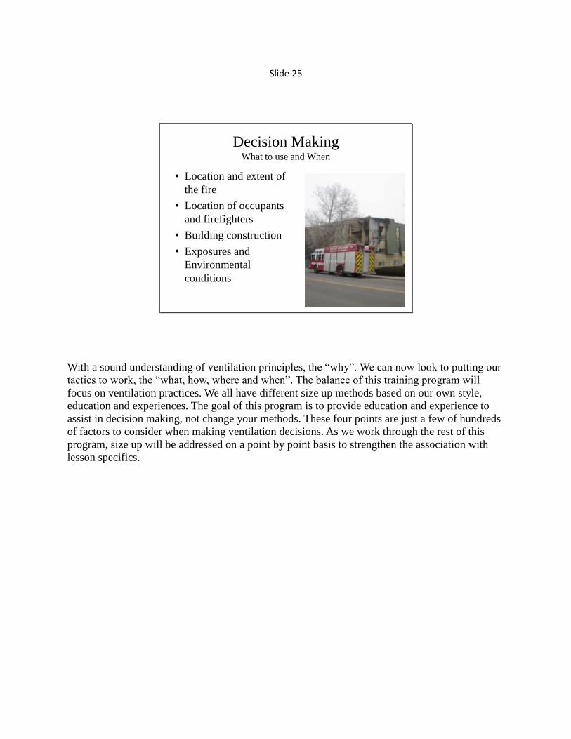
Decision MakingWhat to use and When
• Location and extent of
the fire
• Location of occupants
and firefighters
• Building construction
• Exposures and
Environmental
conditions
With a sound understanding of ventilation principles, the “why”. We can now look to putting our
tactics to work, the “what, how, where and when”. The balance of this training program will
focus on ventilation practices. We all have different size up methods based on our own style,
education and experiences. The goal of this program is to provide education and experience to
assist in decision making, not change your methods. These four points are just a few of hundreds
of factors to consider when making ventilation decisions. As we work through the rest of this
program, size up will be addressed on a point by point basis to strengthen the association with
lesson specifics.

Slide 26
Coordination is Key
We simply can‟t speak to this enough. Back to the first video we watched of the firefighters
opening the door. The lesson remains that fires in enclosed structures are mainly ventilation
controlled. We must recognize the potential in all the actions we take on the fire ground to have
an impact on ventilation.
Today‟s fires are an uphill battle for all the reasons we presented earlier. From synthetic materials
to lightweight construction and reduced staffing we do not need to add to the imbalance by
letting uncoordinated actions give these fires even more ammo.
The first video is from the dash camera of San Bernardino City Battalion Chief Mike Alder‟s
vehicle. This is a working fire in a first floor apartment of a two story multi-family dwelling. At
this time there is one engine crew interior stretching an 1 ¾” to the fire and a second on the
outside stretching a backup line. The one truck company is split. Two from the truck are starting
a search on the second floor and the other two are working their way around the structure as an
outside vent team. That outside vent team is who we want to watch. As they round the corner of
the structure and come into view the engine company calls for the windows. You can see the
officer with the radio confirming the order, followed by his firefighter taking the windows. They
have a significant pressure release which surprises a civilian and a photographer but not the truck
crew. Seconds later, steam conversion and hose stream. Textbook coordination.

Slide 27
Coordinated Actions
Uncoordinated Ventilation
This fire is in a vacant single story single family dwelling. The incident commander has made the
call to vertically ventilate the structure first then, if conditions allow initiate an interior attack.
When the video starts there is a truck company on the roof starting to cut a hole. Two engine
crews have stretched lines to the rear and a RIT team is working to “soften” the building before
attack. What sounds like a well planned and coordinated fire literally changes in a flash. The RIT
firefighter cutting plywood off windows fails to consider the effects of his actions on the fire.
The horizontal ventilation he provides causes the entire first floor to light off. This fire event
chases the truck crew off the roof completely ruining the opportunity for them to direct that
energy up and out as planned.

Slide 28
Vertical Ventilation
“Up and Out”
When vertical ventilation tactics are appropriate and can be performed safely it is the best
method of ventilating enclosed structures. Releasing heat, pressure and toxic gases from a
structure at a high point makes our floor level operations safer, cooler and more efficient.

Slide 29
Vertical Ventilation
• Curb to the cut thought process
– Access
– Wall indicators
– Roof Type
• Pitched / Flat / Arched
• Roof System
– Structure:
» Conventional
» Lightweight
– Covering type
• Fire walls
• Roof top indicators/poke through
• Sounding and “Reading your feet”
Don‟t put the cut ahead of the horse, we have a lot of work to do before we make any carts. Bad
joke, important point. A systematic approach to your tactic that includes collecting information
makes for safer and more confident operations. That being said, if your observations are
indicating the tactic is unsafe you should be equally confident in the decision to stop the
operation. During a class on ventilation at FDIC an instructor made a statement that a good
firefighter takes in everything he can from the “curb to the cut”. He may or may not have meant
for that point to stick but it did.
Here is an example of what my curb to cut thought process looks like if upon arrival of a fire on
Truck X the IC assigned me vertical ventilation.
• How are we going to get on and off the roof – Front, rear, sides? Aerial, ground ladders,
neighboring structure?
• As the ladders go up what are the walls telling me? Frame, masonry? Smoke from eaves? Drain
scuppers in parapets? Reinforcement iron?
• Roof type may be obvious when we pull up. Other times we find out from the tip of a ladder.
• Look over the whole roof before you commit. Tunnel vision quickly sets in once the feet hit the
roof. Consider: layout, access/egress, fire walls, existing openings, vent pipes
• At the wall to roof transition look for construction clues? The roof to wall connection is the
safest and easiest point to check. Open up soffits, expose seams in material even make inspection
cuts.
• When moving on the roof practice solid consistent sounding techniques paying close attention
to feedback through your feet.

Slide 30
Peaked Roofs
Peaked roofs are the most common. There are a number of different styles of peaked roofs
however the common construction element is the downward sloping roof decking from a high
point “ridge” to the exterior walls. There are two additional points on peaked roof design features
to make here. The first is on the safest areas of operation. Roof to wall transitions, valleys, ridges
and hips all offer much greater weight distribution than operating in the field of the roof decking.
While vertical ventilation operations commonly occur in the field of the roof we should aim to
use these construction strengths for access and egress. Secondly, peaked roofs by design act as
funnels. Regardless of what point in the attic space extension occurs smoke, heat and fire quickly
builds and spreads across the highest, narrowest point of construction, the ridge.

Slide 31
What do we have?
Here we have two single family dwellings with peaked roofs. The one on the left was built in the
mid 1980‟s and the one on the right was built around 1920. From the “curb” we can start to
identify elements of the structure including age that can help us determine what we will
encounter when we are operating on the roof.
As a side note the structure on the right was the scene a fire which claimed the life of Denver
Fire Department Lieutenant Richard Montoya. Lt. Montoya was conducting a search of a second
floor bedroom when he became trapped.

Slide 32
Conventional Peaked Roof
Conventional peaked roof construction methods are most prevalent in buildings built prior to the
1970‟s. The use of rafters and ridge beams with quality dimensional lumber makes this roof
system a solid platform that holds up well to time and fire. Unfortunately since the 1970‟s
technology and “value engineering” has made this type of roof construction rarer in modern
peaked roof structures.

Slide 33
Lightweight Roof Construction
Lightweight truss construction methods save builders money and materials while costing
firefighter‟s time and opportunity. The concept is simple, our structural components “trusses”
have a much higher surface to mass ratio than with conventional methods. As you can see in the
picture to the right even the arrangement of the trusses creates an excellent kindling package for
fires in these areas.
Does this mean that we shouldn‟t operate on truss roofs? No! Roofs are systems designed to
support loads. The truss is a critical structural component however it is just one piece. Sheer
support of roof decking, the triangle design and engineered roof to wall connections all come
together for a solid system. What does this mean for us as firefighters operating on peaked roofs.
Thanks to technology vertical ventilation is actually more critical to operations and must be
performed in a much tighter window of opportunity.

Slide 34
Balloon Frame
While balloon frame construction utilizes conventional roof construction the walls of the
structure are built without fire stopping which allows for unchecked vertical fire spread. For this
reason as with truss construction vertical ventilation is more critical to operations and must be
performed in a much tighter window of opportunity.

Slide 35
Ridge Hip Valley Gable
These terms have already been introduced through this program however when it comes to
operations we need to understand that they don‟t just describe construction features they identify
landmarks. Good common terminology can help when the roof crew makes the call for a
“secondary means of egress to the gable end on the bravo side”.

Slide 36
Reading the Structure
The aforementioned landmarks are critical for directing simultaneous operations in separate
locations on incidents occurring in complex structures like this. Shortly after this footage vertical
venting was performed over both exposure occupancies. The video was shot by a bystander on a
second alarm fire in a townhouse complex. The use of this video at this point is for identifying
and naming construction features in real time with real conditions.

Slide 37
Reading the structure
Clearly the task is much simpler with a clear picture and without the distraction of a well
involved occupancy. We can now see that the town home complex is actually two and three unit
adjoining structures not as single units or a common structure.

Slide 38
Roof Ladder Cuts
Since we are on the topic of construction features and we are using this fire it is a good
opportunity to cover roof ladder cuts. The reason we use roof ladders is to improve our situation.
Roof ladders help distribute the live load we place on the roof and improve footing on steep
pitches or bad conditions like snow or rain.
This picture shows the hole cut to provide ventilation of the attic space for the Bravo exposure of
the fire we just reviewed. Roof ladder placement makes accessing the ridge on a steep roof pitch
possible. More specifically the roof ladder placement location next to the chimney takes
advantage of construction features and known framing to improve the safety factor.

Slide 39
Reading the Soffit
In the previous slide the chimney presents us with a clear indicator of where our rafters are for
good roof ladder placement. In the absence of landmark like we can look for other clues in soffits
or even nail patterns in gutters.

Slide 40
Flat Roofs
Flat roofs present the most complex, challenging and time consuming ventilation operations. The
good news is that they also cover larger commercial occupancies with greater fire loads in busy
parts of town. This makes them excellent candidates for signage and cell sites which add
significant loads that the building was never designed to support. I wish this was just a fun little
joke but as you can tell from the picture it is very true. This building which is at least 60 to 70
years old was certainly never designed to support this kind of load on its roof. The bottom line
when dealing with flat roofs is to expect the worst. More than likely that‟s what you‟ll find.

Slide 41
Typical Flat Roof?
According to IFSTA this is “typical” flat roof construction. I will tell you that there is not a
“typical” flat roof. What we could call “typical” is pretty much limited to components. There will
be a structural system that supports some form of decking which allows for application of some
type of water proofing.

Slide 42
Up on the Roof
• Top Side Size-Up
• Primary flat roof duties
– 360 : Look Listen Feel
– Ventilation using existing openings
• Secondary flat roof duties
– Making the cuts
• Inspection Cut
• Ventilation Cut
Flat roofs might as well be called hidden roofs. You cannot properly size up a flat roof from the
ground. We might get some clues from the ground level about the type of roof system by taking a
peek inside the structure. We might be able to determine roof height from the location of drains
all good information but we have to be top side to do a good size up.

Slide 43
What do we have?
By now you should be on to the game. I set you up with some information then I show you a
picture or a video to prove my point.
What do we have? Appears to be a commercial building with a single occupancy? It is tough to
tell because of the poor picture quality but, there may be some type of division in the wall where
the sign is. This wall does not have any visible drains to indicate roof level. The point is that
from here we don‟t know what we have. What we do know is that we need to “expect the
unexpected”.

Slide 44
Go find out
Now what do we have? The unexpected! The wall division has no relation to the structure and
come to find out we actually have two totally different roof systems.

Slide 45
Existing Openings
From the earlier slide we broke up roof duties into primary and secondary. The primary duties
included our size up and ventilation using existing openings. Ventilation using existing openings
is considered a primary duty if they will support the incident and are done in coordination with
other operations just like all ventilation. The reason we put existing openings ahead of cutting a
hole is purely convenience. If we can take advantage of something that is already in place that
may even provide some added level of control like a bulkhead door or roof hatch it saves us time
and resources. Compare it to the “try before you pry” adage for forcible entry.
Slide 46
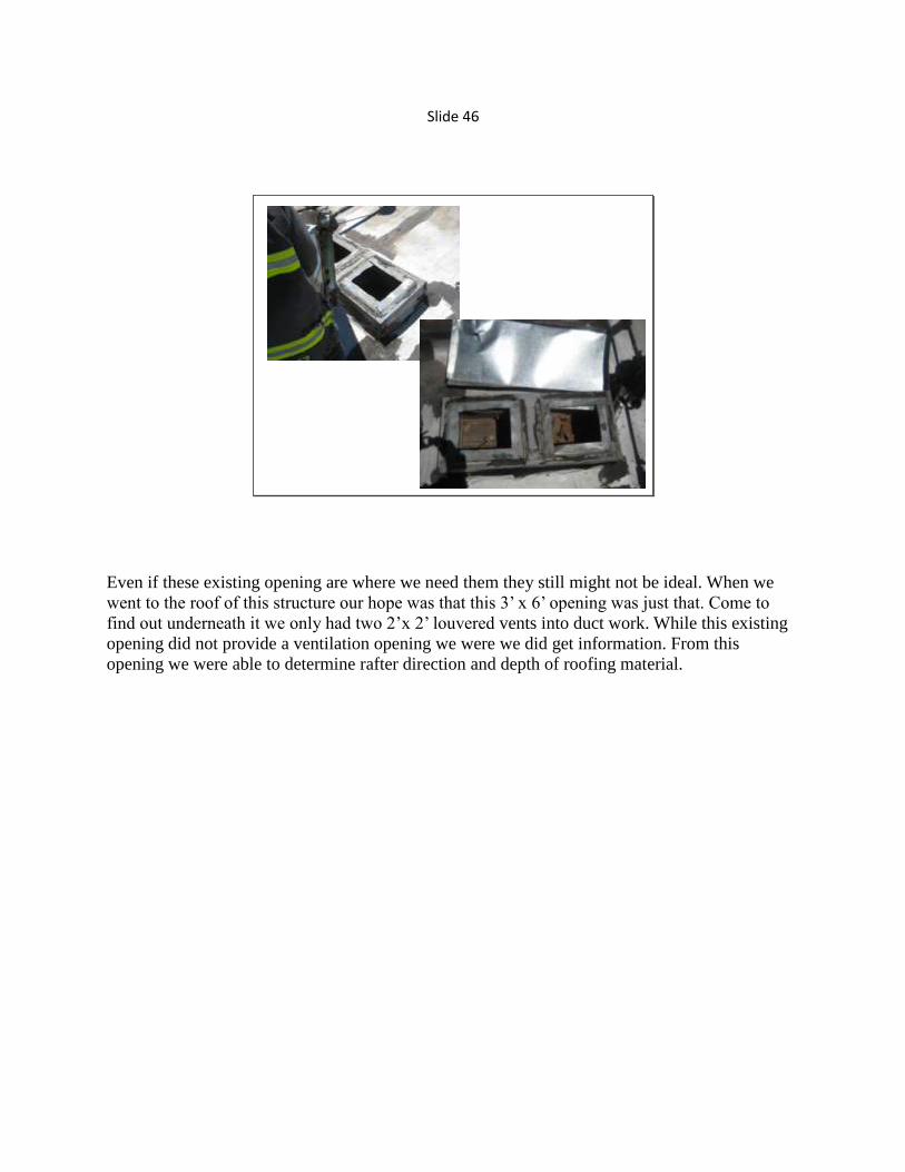
Even if these existing opening are where we need them they still might not be ideal. When we
went to the roof of this structure our hope was that this 3‟ x 6‟ opening was just that. Come to
find out underneath it we only had two 2‟x 2‟ louvered vents into duct work. While this existing
opening did not provide a ventilation opening we were we did get information. From this
opening we were able to determine rafter direction and depth of roofing material.

Slide 47
Concrete Roofs
As there are times when existing openings aren‟t enough, there are also times when that is all we
got. Twin tee concrete roofs like this one are a prime example. Remember that the lack of
vertical options doesn‟t mean that we are without options. We now need to move on to using
pressure and horizontal openings or when all else fails consider mechanical means.

Slide 48
Arched Roofs
Bowstring construction and arched roofs tend to be considered the worst roofs we will encounter.
This reputation is misplaced, from a time in the fire service where we placed blame on things
that were beyond our control in order to avoid responsibility. The driving force behind this
theory is the Hackensack Tragedy.
Height – Volume - Fire load
Height – The reason occupancies are constructed in the arch style is to provide height. This
added height must be one of the first things we consider in our evaluation of these occupancies.
A floor level investigation may not reveal anything, all the while conditions over head could be a
nightmare. Look Up.
Volume- Once again the wide open space that these structures provide is a desired construction
feature. It also means that lack of partitions allow for rapid fire spread.
Fire Load- The picture above is of a local indoor pool. It doesn‟t matter what type of roof you
put over a pool. We know the fire load in there is so low we should be able to operate for a while
before we have any concerns. The same is true for the auto dealership fire except on the other
side of the spectrum. Structural steel, bowstring or heavy timber, heavy fire conditions feed by
vehicles and auto repair materials will destroy any roof system or material in short order. In
closing, vertical ventilation evaluation and operations do not need to change for bowstring
construction as long as we pay attention to what we know about arched roofs and what the
incident is telling us.

Slide 49
Basements
• Earlier consideration
– Bad environments
– Bad access
– Bad place
• Flat roof ventilation
Causing damage for some reason makes the “customer” service; I mean the fire service really
nervous. The only thing that scares customer servers more than cutting holes in customers roof‟s
is cutting holes in customers floors. We must overcome this aversion and recognize the high risks
of a basement fire. Basements are poorly ventilated, poorly accessed and the roof of the
basement (the first floor) typically bears the greatest load. If we plan this operation early, select a
good location like along an exterior wall below a bay window, vertically venting basements can
be done quickly and safely by following flat roof procedures. Bottom line – If you would cut a
hole in the floor to support a RIT operation why wouldn‟t you cut a hole in the floor to prevent
RIT activation.
We love to brag about out the beating we take on basement fires. Funny thing is we only get the
chance to brag about taking a beating when we make it. Don‟t make your kids orphans for
bragging rights-

Slide 50
Horizontal Vent
• Opening Doors
• Taking windows
• Gable Vents?
Horizontal ventilation is considered the quickest and easiest way to relieve structures and
provide ventilation. This combined with the fact that we operate horizontally in structures means
that we must coordinate and communicate all our actions and not let independent actions in the
heat of the moment compromise safety.

Slide 51
Horizontal VentilationSometimes it‟s all you need
It just simply takes more to horizontally ventilate a structure. This video is Houston Fire
Department arriving at a room and contents fire in a small single family dwelling. Upon arrival
there is about a 10 x 10 room well involved with fire out 3 windows. You can see that fire is very
active and it is clean burning indicating it is well vented. The engine crew advances in and makes
quick work of the room.
Two things to note on this fire in particular. The first is that this small room has 3 windows. This
is fairly uncommon for a room of this size however we see that this is necessary to properly open
this room up. If you were to vertically ventilate this room a hole the size of only one of these
windows would be more than adequate. The second point to note is that although the room is
well ventilated for smoke and steam conversion the room is holding a ton of heat. Shortly after
the initial knockdown the fire flares back up. As long as windows are below the ceiling level heat
will remain trapped in the lid.
This fire is about as straight forward as we could ask. Well ventilated ahead of the attack upon
arrival. The small fire area and 3 windows is all we need.

Slide 52
Horizontal VentilationSometimes it‟s just the first step
Row houses, townhomes, strip malls or apartments, any adjoining structures present us with
limited ventilation opportunities. For this occupancy and fire location we have, front, rear and
top as our options. Based on initial smoke conditions this place needs to be opened up right now!
Time sensitivity forces our hand; we need to provide initial ventilation as soon as possible
opposite the entry point to reduce the potential for a significant event in the direction of the entry
crews. Two firefighters ladder the porch roof and take second story windows on the A side.
This is quick, well placed and extremely effective. As good of an example as this is, it is just the
first step. The initial horizontal ventilation improved conditions dramatically however these two
windows aren‟t going to be enough to release the heat of a well involved top floor. A follow up
vertical ventilation hole over the fire rooms would be ideal.
Before I move on there is always a question of “how is this opposite of the attack?” Inside the
front door of nearly all 2 story row houses, condos or town homes you find the stairs. 1st floor
stairs on the a-side bring you up to the 2nd
floor on the c-side. Therefore the 2nd
floor fire attack
at this occupancy will be from the rear out the front.

Slide 53
Taking Windows
• Window Size Up– Location, Location, Location!
• Fire room
• Opposite attack
• Living space
• Exposures
– Conditions
• Fire
• Wind
– Window Type
• Operable versus Non-operable
• Size
• Mechanics
Windows are the most common opening in structures. The quick access, good location and
typical ease of removal make them an extremely tempting choice. As professionals we must
exercise good discipline here. Take into consideration the location and extent of the fire, current
and future operations then size up your window choices. With a good thought process and
informed plan the ventilation operation is then communicated and coordinated.

Slide 54
Taking Windows
Location - This picture is the rear of a strip mall. The 1950‟s era strip mall is constructed around
this 1890‟s era single family. You could fill a day just discussing this one occupancy. For right
now the focus is location. When a location is given “Take the windows in the Bravo Charlie
corner second floor” we have to consider the source and make sure we are targeting the same
area. If command is giving this order a quick face to face or request for him to point out or light
up the location may be a quick and easy way to clear this up. If an interior crew is giving this
order finding out which “Bravo Charlie corner” they are talking about is going to take some
work.
Slide 55
Taking Windows
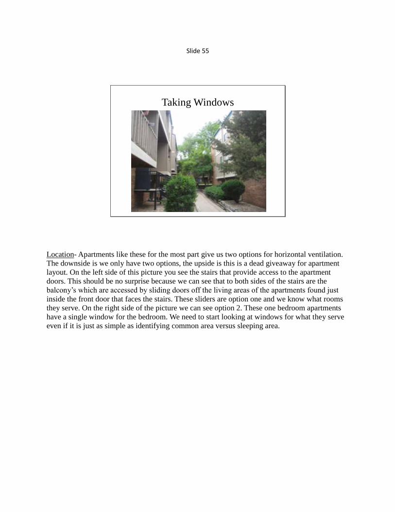
Location- Apartments like these for the most part give us two options for horizontal ventilation.
The downside is we only have two options, the upside is this is a dead giveaway for apartment
layout. On the left side of this picture you see the stairs that provide access to the apartment
doors. This should be no surprise because we can see that to both sides of the stairs are the
balcony‟s which are accessed by sliding doors off the living areas of the apartments found just
inside the front door that faces the stairs. These sliders are option one and we know what rooms
they serve. On the right side of the picture we can see option 2. These one bedroom apartments
have a single window for the bedroom. We need to start looking at windows for what they serve
even if it is just as simple as identifying common area versus sleeping area.

Slide 56
Taking Windows
Because of the cheap construction methods in modern buildings window types give us even more
clues. As a disclaimer these are just clues to layout they are not guarantees. The home on the left
shows us two windows on the Charlie Side. Without the distraction of fire and our minds tuned
to windows and building layout we should be able to quickly identify clues offered by both. The
first floor window sill is at counter height (bathroom or kitchen) the window size is consistent
with a larger room (kitchen). The second floor window is large (bigger room), has screens
(operable) and on the second story (master bedroom). The home on the right gives us a good
example of clues provided by cost saving contractors. On the first floor we see a large window
with standard height sill. Directly above it, on the second floor (where we would expect the
sleeping areas) there is a single, smaller non-operable window. This first and second floor set up
is the same to the right just outside of the picture. What does this tell us about layout?
Contractors don‟t want to spend the extra money on operable windows for an area that occupants
can‟t access. If we believe that the area represented by the first floor windows is a living room
then we can start to think that this living room is open to the second story. This is important for
us to recognize because it provides a high point to ventilate horizontally. This could be the best
point to initially vent a first floor fire.

Slide 57
Taking Windows
Another new construction residence that helps to clears up the non-operable window clue. Just
over the front door and first floor window we see 3 non-operable windows. If we take a quick
look down the Bravo side and see more non-operable windows in this AB corner or no windows
we know with almost complete certainty that this is a vaulted space and not a living area.

Slide 58
Commercial Occupancies
What are we
walking
into?
Earlier in the class we looked at commercial occupancies with store fronts and discussed
ventilation tactics using pressure gradients. Unfortunately if we look at all our commercial
occupancies the ones with store fronts only make up a small percentage.

Slide 59
Taking Windows
For the majority of commercial occupancies, windows are typically undersized for the area they
serve.

Slide 60
Taking Windows
The window on the left is a modern sliding vinyl window. These windows are a firefighter‟s
dream. Putting a Haligan to work on the frame we can remove full panes faster than we can
break and clear out the window. The window on the right is a firefighter‟s nightmare and it has
nothing to do with the bars on the outside. These windows are the “old school” steel frame
casement windows. The glass in these windows is out quick but, the frame is a beast. Clearing
these windows requires a sledge or a saw. A row of these windows like we see on this wall is
going to take a considerable amount of time and resources to clear. The point of this slide is
recognize and plan. An outside vent team on a building with the vinyl windows can be two guys
with hand tools. If you start your 360 and find these steel frame windows with bars, assign a full
company with tools and a saw.

Slide 61
Gable Vents
• Horizontal vent of an attic?
• Typically inadequate opening based on volume of attic
• Must be coordinated to prevent rapid spread.
• Use gables for access not ventilation
Gable vents are designed and installed in attics to allow natural air movement consistent with
natural heating and cooling of the space. The use of gable vents to vent an attic space under fire
conditions is counterproductive. Gable vents are poorly placed and undersized for fire
ventilation.
The picture on the left is a prime example and can be compared to the video of the firefighters
opening the door we watched earlier. If we arrive at an attic fire and take a gable vent for
ventilation this is what we will get; a massive push out that opening as we just provided a low
pressure magnet. Consider how quickly conditions are being compounded in that enclosed space.
If we also think of the heat built up along the ridge the last thing we want to do is pull everything
horizontally. When possible, attic spaces need to be vertically ventilated. Use gable vents or
rooms underneath as access for your hoselines.
Slide 62
Wind
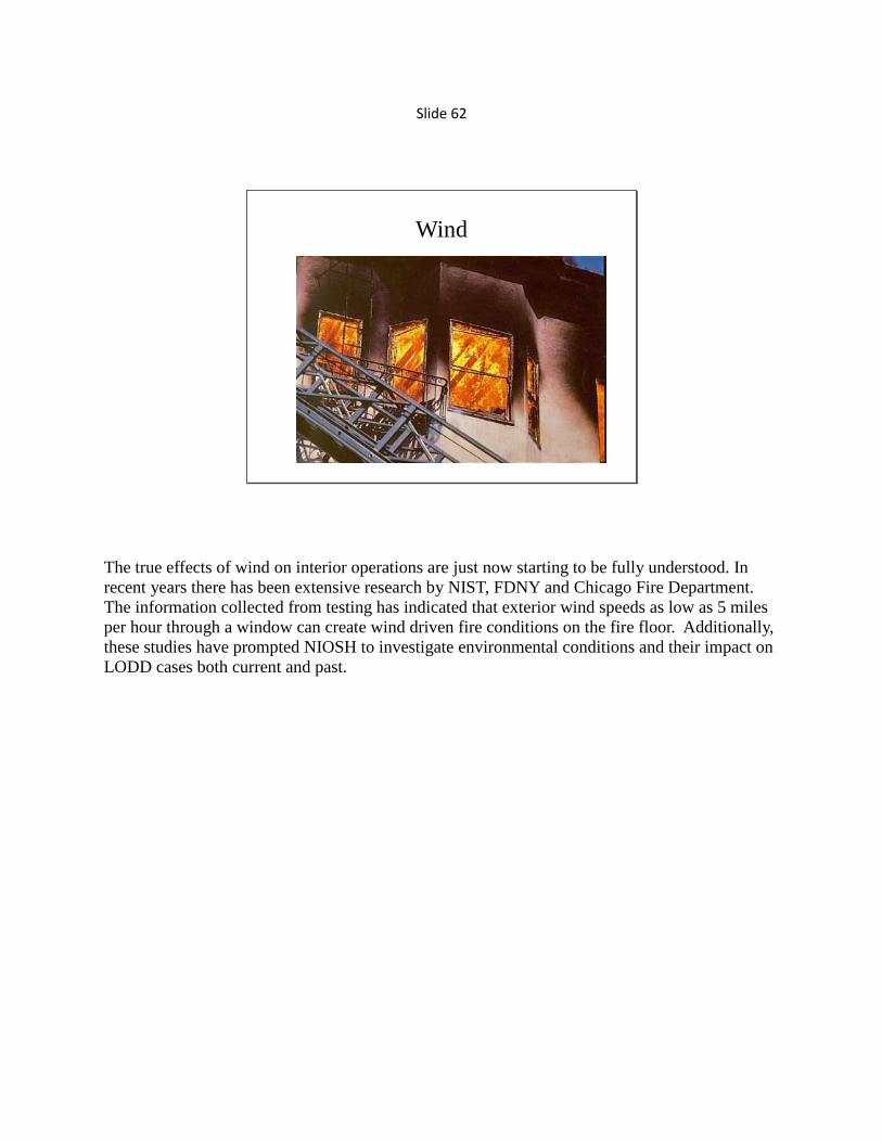
The true effects of wind on interior operations are just now starting to be fully understood. In
recent years there has been extensive research by NIST, FDNY and Chicago Fire Department.
The information collected from testing has indicated that exterior wind speeds as low as 5 miles
per hour through a window can create wind driven fire conditions on the fire floor. Additionally,
these studies have prompted NIOSH to investigate environmental conditions and their impact on
LODD cases both current and past.

Slide 63
6th and Simms
• The wind at ground level was negligible. The window with fire showing is about
25 feet. With negligible winds at ground level, the winds 25 feet off the ground
were significant enough to overcome the pressure of the fire inside this room.
Our department certainly doesn‟t need a new study to show us that wind conditions outside the
fire room can make operations more challenging. These photos are from the live burns we
conducted in 2005. This window is the only opening for a well involved hotel room. Wind was
reported as very light at ground level however at the third floor it was holding the fire to the wall
and even with the steam expansion very little made it exterior.

Slide 64
FDNY Wind Tests
If a picture is worth a thousand words this video is priceless. This apartment building in New
York was used over a month by FDNY and NIST to study wind driven fires. Here we have a well
involved bedroom fire, door closed in a 3rd
floor apartment. The video was used in a class at
FDIC given by one of the NIST scientists on the project. He described the puffing action as
“over pressurization” of the fire compartment. Imagine where all that energy would be going if
the door to that bedroom opened.

Slide 65
NIST Wind Video
Here is a video complete with thermal imaging of what happens when the door to the fire room is
open with a 20 mile an hour wind. Let‟s see if this is the wind driven fire you pictured.
The scenario prepared by NIST is a fire that starts on a mattress in a one bedroom apartment. The
occupant discovers the fire and evacuates leaving the doors open on the way out. As the fire
builds in the room, the window for that room fails and the exterior wind at 20 miles per hour is
introduced.
The footage is of the four simultaneously running cameras. The upper left view is of the fire
room from the bedroom door. The upper right view is of the common area of the apartment from
the apartment door. The lower left camera is looking at the open apartment door from the public
hallway and the lower right view is a thermal imaging camera at that same angle. The thermal
imaging camera also provides us a surface temperature reading of the masonry wall 3 feet off the
ground at the apartment door.
For the first two minutes we observe fire growth and can see smoke and heat move through the
apartment and out into the hallway. At 2:21 the window fails and the wind impacts the fire. At
2:30 the wall temperature is 80 degrees over the next minute that wall temperature reaches over
900 degrees at 3 feet off the ground. At just over 3 minutes all the protected conventional
cameras have failed due to high temperatures. Additionally all of the thermocouples they placed
were destroyed after maxing out at 2500 degrees including the one at the ceiling in the public
hallway.
When possible wind conditions must be evaluated at the window prior to taking it.

Slide 66
Operations
This firefighter is going to work. Carrying two ladders he is a very determined man. Sure there
are easier and more organized ways to move equipment. Yes, the top floor of that building is well
involved, and certainly the guy holding the camera could help him out. The point is this is a cool
picture of a guy carrying two ladders.

Slide 67
Getting it Done
Study – Practice – Drill – Preplan
The last picture was a guy going to work in stereo typical “Truckie” fashion. This picture is a
professional crew, working with purpose in an organized fashion just as they have trained. They
accessed the roof to a structurally sound point at the ridge. They brought appropriate tools
including a roof ladder at the ready. The sounding firefighter is leading the operation and
popping vents as he goes, while the saw man is keeping an eye on his partner and awaiting cut
direction.
My chief looked at this picture and saw a firefighter not wearing gloves. I look at this picture and
see two firefighters working as a team. Both confident and efficient in their assigned tasks,
functioning with discipline in a safe well coordinated manner. In today‟s fire service with fire
incidents declining every year this level of proficiency can only come from practice.

Slide 68
Professional Work
Another video from San Bernardino City Fire. This one provides us with real time footage of
operations. The key point of focus will be the first arriving 4 person truck company that is sent to
the roof to ventilate. We will see the truck officer and two firefighters at the base of ladder on the
Alpha Bravo corner. What we can‟t see is the fourth firefighter from the truck throwing an egress
ladder on the Charlie side.
First up the ladder is the sounding firefighter with the hook. It is difficult to see but when he gets
on the roof he immediately begins sounding over to the fire occupancy to determine cut location.
Next up the ladder is the saw firefighter. By the time he gets to his partner it is time to cut. The
saw man is 100% task oriented with the running saw in his hands so the sounding man becomes
his back up. Just as the officer starts up the ladder he is joined by his fourth firefighter. When the
officer gets on the roof he keeps a slight distance to keep an eye on both the operation and fire
conditions.
The first hole is a success and provides good ventilation but the officer determines more is
needed and calls for a second hole. The two person team drops back, the sounding man selects
cut location and the process repeats itself. The second hole complete and the officer calls it good.
You can see that smoke conditions at the windows have improved. The crew reassembles, heads
up and over the ridge sounding as they go to the egress ladder. Why doesn‟t the crew leave the
roof the way they came? One simple wind change and that ladder could have been a nasty place.
With the primary ladder providing the quickest access to the cut it is the most vulnerable after the
cut. The added safety and protection of the long way off may be quicker in the end. Furthermore
the repetition of using egress ladders for egress sets up best practices.

Slide 69
Be safe by thinking ahead
Steam conversion is a good thing to see at a fire and it means we are making progress. It also
may obscure places that were clear earlier, just the same as a wind shift. Plan ahead and call for
more ladders, two is not enough for this situation.

Slide 70
How many firefighters does it take?
There are places where you can have too much of a good thing, even staffing. Under certain
conditions it can be argued that we need more people to improve safety. For the most part I agree
as long as roles and responsibilities are clear. In the San Bernardino City video we just watched
in that occupancy with those fire conditions sending a full crew to the roof is a good call. The
tactic of the actual cut only requires two people. The safety of the operation is improved when
the additional show good discipline and stay in a position to evaluate the bigger picture.
This video from Houston show us that no matter how many people are involved if the tunnel
vision is on, no one is maintaining situational awareness.
The access ladder is thrown to a corner which is common practice because it is easily
landmarked and it s a structurally sound point. The downside to laddering a corner is that it is a
point where two walls come together and on the roof walls are edges. The firefighter who fell
should have been well aware of his proximity to the edge when he stepped on to the roof
however the tunnel vision of the task cost him his situational awareness.

Slide 71
The Cuts
The first thing we tend to think of when we hear “ventilation” is cutting roofs. So why is it the
last thing we are going to talk about? Because, as soon as you get your hand on that saw, your
world becomes small and loud. This is the worst time to start and stop, or try to communicate
plans. The goal is that the training you have done combined with the information you take in and
process up to that point you can comfortably and confidently put your head down and go to work
without interruption.

Slide 72
4 x 4 Vent Holes
• History of 4x4 holes– From the pre-saw fire service
– Rafter and plank roof construction
– Single family homes were more typically about 1000 Sq ft
– Contents of homes were mainly Class A combustibles
• Today‟s use of 4x4 holes– Field cuts for smaller single room
vertical ventilation
– Considered the minimum • Modern construction has larger more open
floor plans
• Fuels burn hotter and less completely
• Structural members are lighter weight
The old standard 4x4 hole for vertical ventilation is just that, an old standard. Today most of our
vertical ventilation operations will require more square footage. That said, a 4x4 hole may be
more than adequate on the next fire you go on. The point is that we think of it as a minimum and
not the goal. Training should be focused on cutting 4x4 holes and planning for the potential that
more may be required. This helps us develop a good visual gauge of size and time as well as
keeping a thought process that is towards planning ahead.

Slide 73
Hand Tools
• Roof Pitch
• Access
• Saw failure
With a steep pitch and tight valley a the roof ladder or chainsaw may just crowd the situation.
Going to work with hand tools at times may be the best route. The final and obvious situation for
hand tools is saw failure. Make a back up cutting tool part of your package.

Slide 74
Why A Specific Cut Order?
• Simple - Consistent – Safe
– The cut order is designed to keep members out of
the cut areas and working towards their means of
egress or windward side. During the loud
operational period it also decreases the need for
communication between crew members as to what
will need to be done next.
From this point forward we will focus on one cut order. This cut order can be expanded as
needed from a simple peaked roof field cut, to a large scale flat roof operation. With a common
cut order for all our operations we help reduce communication, keep operations consistent and
improve overall safety. With that being said this is not a requirement as much as it is an option
and recommended practice. Our experience shapes our practices and if you have a sound method
that keeps you safe, out of cut material and working towards your egress you do not have to
change. We do ask that you preplan your cuts with your partner so needs can be anticipated and
the operation is not delayed.
Slide 75
Single Rafter Louver
1
2
3
4
5
EGRESS
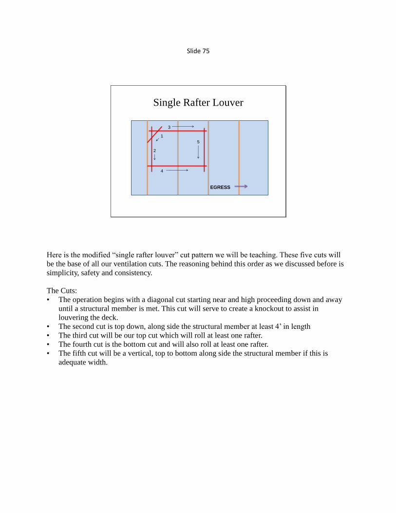
Here is the modified “single rafter louver” cut pattern we will be teaching. These five cuts will
be the base of all our ventilation cuts. The reasoning behind this order as we discussed before is
simplicity, safety and consistency.
The Cuts:
• The operation begins with a diagonal cut starting near and high proceeding down and away
until a structural member is met. This cut will serve to create a knockout to assist in
louvering the deck.
• The second cut is top down, along side the structural member at least 4‟ in length
• The third cut will be our top cut which will roll at least one rafter.
• The fourth cut is the bottom cut and will also roll at least one rafter.
• The fifth cut will be a vertical, top to bottom along side the structural member if this is
adequate width.

Slide 76
An example of the “single rafter louver” at a garage fire. This roof is of truss construction with
structural members on 24” centers. A single rafter louver in this roof provides us with almost the
full 48” width.

Slide 77
Field Cut
• Over the fire room
• Create the “Chimney Effect”
When it comes to peaked roof ventilation we are going to talk about field cuts and ridge cuts.
The field cut refers to the cut location being in the field of the roof. Since most rooms are located
along exterior walls the holes we cut to vent them will fall in the field. As we showed in earlier
slides field cuts will be a two step process. Cutting the decking of the roof then punching the lid
of the room to release the heat and create the chimney effect.

Slide 78
This video demonstrates the expanded cut and a few other points can be discussed.
• The diagonal cut and first vertical are made with the same hand position. The hand position
is changed for the next two horizontal cuts. This process repeats itself for as cuts change
from vertical to horizontal this limits the need for the firefighter to change body position and
prevents work over the cuts.
• With both crew members understanding the cut order no verbal communication is required
during the operation. The sounding firefighter determines cut location and indicates with the
tool where he wants the hole with the angled motion. He then moves into a position to back
up the saw man until he sees that the saw man is about to make the 5th
cut. As the saw man
makes the 5th
cut the sounding firefighter gets his hook into place to prevent drop in and
awaits the saw firefighter to complete the cut before opening up. Once the saw man starts on
the second louver the sounding firefighter opens up and initiates ventilation.

Slide 79
Ridge Cut
• Peaked roof
construction
• Attic fires require
larger holes
• Hallway vent
• Increased obstruction
potential
• Use construction
features to your
advantage
The second peaked roof cut is the ridge cut. The ridge is the location to vent attic fires, larger
rooms that may take up more than half the occupancy or fires that involve center hallways.
If you are venting a room or hallway from the ridge there are two major considerations. First is
to have a hook of appropriate length to reach the lid of the room. The second is to be prepared to
encounter stored belongings which may completely negate this ventilation option.

Slide 80
Single Rafter Louver Expanded
3
1
2
Repeat as necessary
EGRESS
5
4
As mentioned earlier a 4‟ by 4‟ hole is the minimum not the goal. By running the third cut long,
rolling two rafters and moving the fifth cut between the two rafters you can double the size of the
hole with just two more cuts.

Slide 81
Ridge Cut
Here is a perfect example of the funnel effect of peaked roofs. This vehicle fire in Castle Rock
extended to the attic of this structure through the eaves. The truck company quickly accesses the
ridge via the aerial and with a well placed hole relieves a significant amount of heat and pressure.
This is a reminder that regardless of the point which the extension is introduced to the attic space
the ridge must be addressed. Many times I have heard concerns that venting at the ridge will
draw the fire to that location. The simple fact is that heat and peaked roof construction is what
draws the fire to the ridge. Cutting a hole early is the only way to prevent lateral spread once it
gets there.

Slide 82
With about a 2500 Sq Ft. footprint this attic needs a significant hole to properly
ventilate the volume it holds. At least a 4 x 8 to 4 x 12 depending on fire extent
remembering when expanding your hole do so along the ridgeline in a rectangle.
Large Area Peaked Roof
Plan ahead, then plan ahead and when you‟re done, plan ahead. With good saw techniques hole
can quickly be expanded. When we are venting attics at the ridge the hole does not need to be
continuous. If the initial hole appears to be insufficient you can drop back to a safer location and
make additional holes as long as they remain at the ridge

Slide 83
Single Rafter Louver Expanded
1
2
3
Repeat as necessary
EGRESS
ROOF PEAK
Soffit
One more look at an option for expanding our ventilation opening.

Slide 84
Here is an excellent example. The first hole is well placed but the hole appears to be
overwhelmed. The crew drops back a few feet and starts another hole still working towards their
egress as a team of two with the officer providing eyes over the whole operation.

Slide 85
Boise Fire 2 Story MFDArrival Alpha Side
Boise Engine 4 arrived to find this working fire in a second story apartment. On the A-side is the
open stairwell to a short open hall which access the two second floor apartments.

Slide 86
Charlie Side
From the Charlie side we have a well involved bedroom fire out the window in the Bravo Charlie
corner. If a crew was on the roof at this moment a good sized field cut over the room would be
perfect. Looking at this from the dashboard of the truck company pulling up, I would plan on
getting to the ridge and venting for an attic fire. The auto exposure of the eaves will be into that
attic space in short order.

Slide 87
Flat Roofs
• Property conservation venting?
• Vertical ventilation need is greater yet window
of opportunity is smaller
Recently I was told that putting firefighters on flat roofs was ridiculous since it is just “property
conservation venting”. I believe he was speaking about unoccupied commercial structures. If
that was the case and he was speaking about risk versus benefit considerations, I guess I agree
with him. That said, there are a lot of assumptions and I hope that what he said was not what he
meant.
While the majority of flat roof occupancies are commercial, a fair amount of multi-family and
extended care facilities with flat roofs. We are also going to see fires in commercial occupancies
that we can safely operate in with ventilation. We should be safe and constantly perform risk
benefit analysis. This does not mean we take defensive positions as soon as we hear everyone is
out of a structure.

Slide 88
Inspection Cuts
• Construction materials
• Rafter direction
• Depth of cut
• Initial indication of
conditions
• Early and often on
questionable roofs
Inspection cuts are great opportunities for us to slow down and pick up a little more info before
we fully commit to the ventilation operation. A simple 3 sided cut that is large enough to fit your
arm through. Cutting an inspection cut at our roof to wall transition will keep us in a structurally
sound position, tell us the depth of roofing material and may even reveal rafter direction. Once
we are out over the field, if the inspection cut shows good smoke we just expand our cuts from
there and it becomes the knock out for opening up.

Slide 89
Don‟t fear the saw
Respect and Understanding•Know the tool
•Know the task
•Know the situation
There is a direct coloration between risk of injury and comfort level. We are the most dangerous
when we fear an operation (uncomfortable) and when we are complacent in an operation (too
comfortable). Aim for the middle by respecting the tools and tactics
Know the tool:
•Our circular saws with a warthog blade are an impressive machine and for most operations the
saw requires very little help other than direction and drag.
•With the inboard mounting the blade is inline with the handle, as our hand goes the cut goes.
Keep body weight off the saw and positioned behind the handle so that as structural members
are encountered the difference is easily sensed.
• Know the task:
•Having the cut order and length planned will limit starts and stops.
• Know the situation:
•Fire conditions and location
•Your location on the roof
•Egress direction- Obstructions – Edges
•Roof construction
•Depth of material – Type of structural members
•In built-up roofs burying the saw may not be enough to reach the decking, requiring
more cuts
CIRCULAR SAWS WITH RUNNING BLADES DO NOT COME OFF THE DECK
Lack of a break, the saw power and blade mass exaggerate movement in free space make them
very dangerous when operated outside of material

Slide 90
7 9 8 cut / Coffin Cut
Single Rafter Louver Expanded
EGRESS
The most common flat roof cuts are the 7 9 8 cut and the Coffin cut. Both these cut processes
are essentially just an expanded version of the single rafter louver. Once again if you are trained
and consistent in these other cut methods please continue. The single rafter louver base and
common cut order for all roofs will continue to be our teaching method for the afore mentioned
reasons.

Slide 91
Let‟s walk through the cut process:
Up to this point the sounding man has determined cut location and indicated to the saw man
where he wants it by marking the diagonal. The saw man dropped in a diagonal cut until he felt
the resistance of the structural member an stopped. His next cut is along the structural member to
a length he feels appropriate then he stops and moves to the full length top cut where we pick
him up in this picture. Note the firefighter has good positioning with the saw. His body weight is
entirely behind the saw and in line with the blade. With the power of the saw and aggressive cut
of the Warthog blade we as operators simply mind the saw as we drag it through the material.
This “light” touch will prevent binding and help us detect structural members.

Slide 92
With the full length top cut complete we can see the knock out cut has dropped in and the overall
cut looks like a 7. The next series of cuts will be done two at a time alternating from horizontal to
vertical.

Slide 93
The horizontal cut rolls one rafter and runs up to the next structural member then stops. The saw
man then repositions and drops his vertical cut in between the two rafters to facilitate the first
louver.

Slide 94
The next cut follows suit and may be continued for several more if necessary.
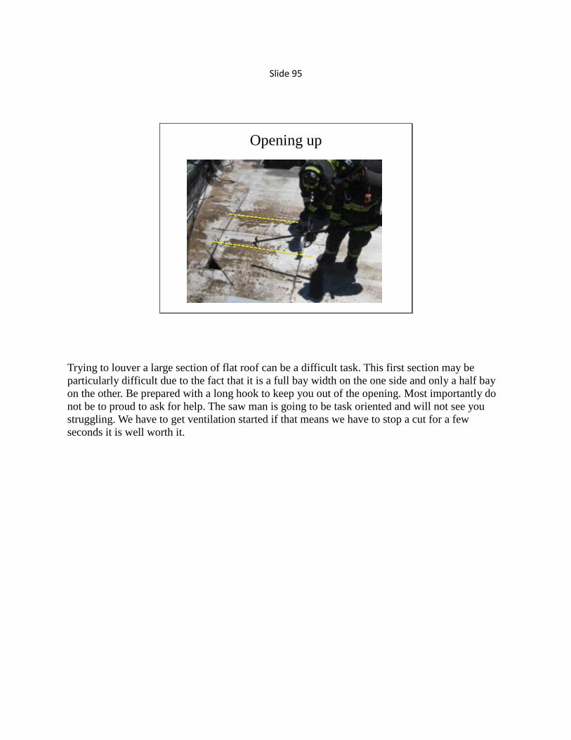
Slide 95
Opening up
Trying to louver a large section of flat roof can be a difficult task. This first section may be
particularly difficult due to the fact that it is a full bay width on the one side and only a half bay
on the other. Be prepared with a long hook to keep you out of the opening. Most importantly do
not be to proud to ask for help. The saw man is going to be task oriented and will not see you
struggling. We have to get ventilation started if that means we have to stop a cut for a few
seconds it is well worth it.

Slide 96
Here we have the saw man finishing his cutting operation. He is showing good body positioning
and simply minding the saw through the material. The sounding man has opened up as they‟ve
gone and with the completion of this cut and final louver they will be done and off.
We can see to his right that the vent hole has run out of real estate due to the location of the roof
top unit. Fortunately the hole he has cut is of good size and his operation is done.

Slide 97
The Trench Cut
Defensive tactic to create a fire break in the roof.
The trench cut is very misunderstood. The trench component of the trench cut is to create a fire
break and provide access for fire streams not ventilate the cockloft.

Slide 98
• Order of operation:
• Large vent hole over fire area
• Observation cuts
• Cut trench at narrow point and pull ceiling but do not pull the trench
• Position hose lines underneath and above
• When fire shows from the observation cuts pull the trench and operate hose lines into the trench
The trench cut was developed during the 1960‟s in New York city during an exceptionally busy
fire era. The tactic was brought outside the city when the first edition of John Norman‟s Fire
Officers Handbook was published. This slide outlines the requirements for a trench cut operation.
Note that the first order of business is a large vent hole over the fire area. The key points seem
simple, clearly explained in his text and logical given certain situations, so why the confusion.
At about the same time John Norman published his book, John Mittendorf also published a book
on truck company operations which describes “strip ventilation”. Strip ventilation is essentially
what we described earlier as expanding the louvered cuts or adjusting your louvered cuts to the
roof layout. Strip ventilation is a ventilation opening for the purpose of venting. An expanded
single rafter louver cut that runs 8 to 10 feet along the ridge of the roof could be considered
“strip” ventilation.

Slide 99
Trench Cut in a Strip-mall
More labor intensive due to the fact it requires two trenches and the absence of a narrow point to aid in
you cut.
MAIN
VENT
Observation cuts
T
R
E
N
C
H
T
R
E
N
C
H
EXPOSURE D EXPOSURE B
Some may ask since we don‟t have H or E type tenement buildings when we would use trench
cuts. Any type of flat roof on a “winged” building will work however the most common
application in most suburban departments is limiting extension in strip-malls. This would be an
example of set-up for a center unit.

Slide 100
Trench Cut in a Strip-mall
Here we have the side view of a trench operation. The main vent over the fire area may be burn
through or a hole cut by firefighters. Observation cuts are placed between the main hole and the
trench to provide indication of fire travel . Then lastly we have the trench cut which is that fire
break in an area which hoselines can be safely staffed and operated. The trench cut is not to be
opened until the observation cuts are indicating the fire is moving towards the trench. With the
common cockloft early opening of the trench will potentially draw fire.
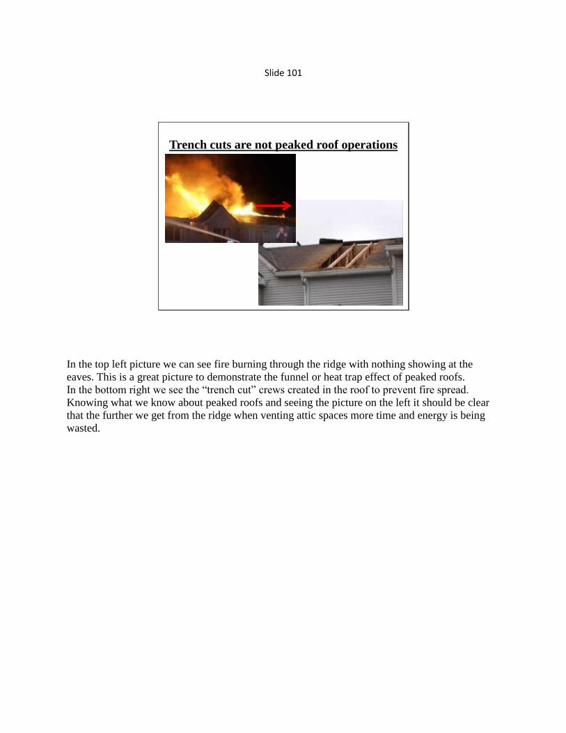
Slide 101
Trench cuts are not peaked roof operations
In the top left picture we can see fire burning through the ridge with nothing showing at the
eaves. This is a great picture to demonstrate the funnel or heat trap effect of peaked roofs.
In the bottom right we see the “trench cut” crews created in the roof to prevent fire spread.
Knowing what we know about peaked roofs and seeing the picture on the left it should be clear
that the further we get from the ridge when venting attic spaces more time and energy is being
wasted.

Slide 102
For attic fires, heat and pressure build at the highest point. In a peaked roof it is the
ridge in a flat roof it is the deck. For this reason time and efforts are completely
wasted the further from the ridge we work. To prevent horizontal fire spread in a
common peaked roof attic space vent along the ridge.
“Strip Ventilation”
Here we have a graphic to show a good “Strip Vent” location along the ridge. Due to the high
and narrow point of the ridge this is where fire will be moving horizontally first. It will take a
very long time for fire to show at the eaves. In flat roofs a strip vent can go in any orientation
simply because in flat roof constriction the roof decking is the lid of the cock loft.

Slide 103
Strip Vent
Single Rafter Louver
1
2
Repeat as necessary
EGRESS
ROOF PEAK
Soffit
As we mentioned before, plan ahead. By running the top cut long the hole is easily expanded one
rafter at a time with the horizontal then vertical cuts.

Slide 104
Final Notes
Trench Cut and Strip Vent
• Strip Ventilation
– Used for Venting fire and smoke
– At the ridge in peaked roofs
– Any orientation on flat roofs
• Trench Cut
– Associate Trench with Fire Break
– Used for hoseline access
– Last stand location

Slide 105
Getting it Done
• Ventilation size up
– Building Construction
– Fire Behavior
• Ventilation safety considerations
• Plan your exit before you need it
• Always have two ways off
• Delegate more ladders if needed
Time to start wrapping this up. Hopefully at this point with the principles and examples we have
presented you have developed a ventilation size up that works for you. Do not forget the risks
associated with these operations. Support each other. The saw man is the extra eyes for the
sounding firefighter as he works his way across the roof. The sounding firefighter becomes the
back up for the saw man when the saw is running and his blinders are up. Plan your exit, plan
ahead and for everything have a plan B.

Slide 106
Getting on the Same PageThe pre-game starts with common terminology
– Construction
• Ridge, Hip, Valley, Gable, Eaves
• Slider, Double Hung, Casement
– Equipment
• Saws
• Tools
• Primary Ladder, Secondary Ladder
– Operation
• Inside Team, Outside Team
• Saw man, Sounding man, OVM
Start by ensuring you are speaking the same language. Acronyms and slang may be our curse. I
tend to just refer to the roof saw as the Warthog and when I think of a hook I immediately think
of a 6 foot steel Halligan hook. Most of my crew understands this but a newer firefighter or even
a very senior firefighter who hasn‟t worked with me may not know what I am asking for.
Something as simple as rounding the truck, tower or ladder, whatever you call it may help to
clear some things up.

Slide 107
Company Level Expectations
Tower X Fire Ground Responsibilities
Inside Team
Gain primary access
Conduct search
Fire – Victims – Extension
Pre and post-control overhaul
Salvage of property
Outside Team
Provide for secondary access/egress
Perform 360‟ and topside size-up if
necessary
Laddering
Fire Floor – Floor Above - Roof -
Opposites
Most company officers discuss expectations with their crews. Adding a fire ground
responsibilities component to it can help crews anticipate what should be done next. Something
as simple as a priorities list can go along way in reducing communication and the delay in
moving from task to task.

Slide 108
Tactical Action Plans / Job Sheet
Ventilation-
– Horizontal
» Must have direct communication
» Confirmed and Coordinated
» Considerations
• Size up
• Fire conditions
• Wind
• Exposures
– Vertical
» FF1
• Primary ladder, Sounding tool
• Leads to and directs cuts
» FF2
• Secondary ladder
• Saw and Secondary cutting tool
• Performs cut
» Additional members
• Operational oversight/safety
• Labor assistance
Tactical action plans or job sheets are the key to doing as we drill. Take what we have covered
today to your crew and develop drills that become your system for operation. This is a simple
example it can easily be expanded or reduced to fit crew specifics.

Slide 109
Tool Assignment Example:2 Person Vertical Vent (Typical Single Family)
FF #1 – Primary ladder and sounding tool/hook
Putting it on paper means nothing until we do it. Take the time practice your plan and see what
works. Officers, take the time to show your expectations not just speak them.

Slide 110
Tool Assignment Example:2 Person Vertical Vent (Typical Single Family)
FF #2 – Secondary ladder, saw and back up cutting tool

Slide 111
Questions?
Compiling this information into one program has been a lot of work however, the work is not
done and I look to you for help to improve it. Please be honest and constructive in your feedback
so we can provide better programs in the future. In closing the information presented in this class
is 99.9% collected and .1% created. Recognizing that this class would not exist without others
sharing information with me, I will make this entire class, videos, pictures and resources fully
available for you to pass on as you see fit.


![PRINCIPLES, PRACTICES, AND SOCIAL MOVEMENTS · 2006] PRINCIPLES, PRACTICES, AND SOCIAL MOVEMENTS 931 practices. Yet, even though principles like the anticlassification prin-ciple](https://static.fdocuments.in/doc/165x107/5ebe1b38c94693584f0b4160/principles-practices-and-social-movements-2006-principles-practices-and-social.jpg)