TRIBOLOGY LETTERS 1 Adhesion-RelatedFailure...
13
TRIBOLOGY LETTERS 1 Adhesion-Related Failure Mechanisms in Micromechanical Devices C. H. Mastrangelo Abstract— Adhesion-related failures occurs in microelectromechanical systems (MEMS) when suspended elastic members unexpectedly stick to their substrates. This type of device failure is one of the dominant sources of yield loss in MEMS. This paper reviews the physical mechanisms respon- sible for the failure from both the theoretical and practical stand point. In general, the failure requires two different phenomena. First (a) the device must be subject to a force sufficiently strong to collapse the elastic member thus bringing it in contact with the substrate. (b) After contact is estab- lished and the force removed, the intersolid adhesion must exceed the elastic member restoring force hence keeping the device permanently pinned to the substrate. Both of these problems develop during the device fabrication as well as during the device operation. Normalized elastic member dimension bounds for prevention of collapse and pinning are presented. The failure rate can also be reduced using a wide variety of processing, surface treat- ment, and physical schemes. These are discussed in regard to their practical applicability. Keywords— Adhesion in MEMS I. I NTRODUCTION Microlectromechanical systems are micrometer-size systems capable of interfacing electrical world to mechanical signals. These devices have a wide variety of applications performing basic signal transduction operations as sensors and actuators. MEMS are usually constructed using lithographic processes de- rived from VLSI technology. Because these devices must react to mechanical signals, many of these use construction topologies that require physical mo- tion. For example, an accelerometer-type device translates the motion of a suspended proof mass into capacitance which is later converted to a voltage output. Similarly, micromechanical mir- rors must be able to deflect a light beam in a particular direction. Suspended micromachined structures such as plates and beams are commonly used in the manufacturing of pressure [1–4] and acceleration sensors [5, 6]. These structures are typically made by forming a layer of the plate or beam material on top of a sac- rificial layer of another material and etching the sacrificial layer [7, 3]. These microstructures have relatively large areas, but a very small stiffness. At the same time these elements are fabricated a few microns from their supporting substrate. The combination of these three characteristics makes MEMS devices highly sus- ceptible to surface forces which can cause the suspended mem- bers to deflect toward the substrate. Under certain conditions, the elastic member can collapse and permanently adhere to their underlying substrates causing a device failure. Namely, this can happen both during the device fabrication and normal use. During processing, adhesion can occur when the suspended member is exposed to an aqueous rinse and dry cycle. Since the device-to-substrate gap is so small, strong attractive capillary forces can develop during the dehydration causing its collapse Department of Electrical Engineering and Computer Science, University of Michigan, Ann Arbor, MI 48109-2122, USA and subsequent pinning to the substrate. [7–11]. Nathanson and Guldberg [12] recognized that small mechanical structures are influenced by surface tension forces. Guckel and Burns [7] ob- served that when microscopic elastic plates are rinsed and dried, the capillary forces acting on these are large enough to bring them in contact with their underlying substrate. They also ob- served that, after complete drying, some of them remain pinned to the substrate held by attractive forces rendering them unus- able. A number of researchers have proposed different mecha- nisms to explain these forces. Scheeper et al. [9] proposed that the adhesion is caused by water molecules adsorbed on the ad- hering surfaces [13]. Alley et al. [14] proposed that the adhesive bond is formed by silica residues that remain on the substrate af- ter the water has evaporated. The same collapse can develop when the device is under nor- mal operation if it is exposed to high humidity conditions lead- ing to capillary condensation [15] (hence the formation of a wa- ter droplet in the gap). A third yet possible adhesion failure mode develops if the suspended member is placed in contact with its substrate by external forces. This may be done by the de- liberate placement of a collapsing force or by accidental shock. The pinning process is hence divided into two stages of (a) mechanical collapse and (b) adhesion to the substrate. If any two of these is eliminated, the adhesion failure does not occur. In practice, either mechanism can be prevented provided the stiff- ness of the microstructure is high enough. Therefore there ex- ists a characteristic physical parameter that determines the onset of the failure. The presence of the failure threshold is readily observed experimentally by constructing an array of progres- sively weaker suspended elements followed by examination of the sticking condition. Figure 1 shows a photograph of an array of micromachined polysilicon cantilever beams showing clearly the onset of the pinning condition at a particular beam detach- ment length. The same phenomena happens for other suspended micromachined structures such as doubly supported beams and plates as shown in Figure 2. This paper discusses a general review of the causes for these phenomena and several common techniques used to alleviate the problem. In Sections II and III we discuss theoretical models for both stages, and provide two bounds on the physical dimen- sions of the suspended member that eliminate the failure. In Sections IV and V various techniques used to eliminate the ad- hesion failure are discussed. These are divided onto physical schemes that attempt to minimize the contact area and chemical schemes that minimize the intersolid adhesion. The paper con- cludes with some general comments about the practicality of the methods at hand.
Transcript of TRIBOLOGY LETTERS 1 Adhesion-RelatedFailure...

TRIBOLOGY LETTERS 1
Adhesion-RelatedFailureMechanismsinMicromechanicalDevices
C. H. Mastrangelo
Abstract— Adhesion-related failur es occurs in microelectromechanicalsystems(MEMS) when suspendedelastic members unexpectedlystick totheir substrates.This type of device failur e is oneof the dominant sourcesof yield lossin MEMS. This paper reviewsthe physicalmechanismsrespon-sible for the failur e fr om both the theoretical and practical stand point. Ingeneral, the failur e requirestwo different phenomena.First (a) the devicemust be subject to a forcesufficiently strong to collapsethe elasticmemberthus bringing it in contact with the substrate. (b) After contact is estab-lishedand the forceremoved,the intersolid adhesionmustexceedthe elasticmemberrestoringforcehencekeepingthe devicepermanently pinned to thesubstrate. Both of theseproblemsdevelop during the device fabrication aswell asduring the device operation. Normalized elasticmember dimensionbounds for prevention of collapseand pinning are presented.The failur erate can alsobe reducedusing a wide variety of processing,surface tr eat-ment,andphysicalschemes.Thesearediscussedin regardto their practicalapplicability.
Keywords—Adhesionin MEMS
I . INTRODUCTION
Microlectromechanicalsystemsaremicrometer-sizesystemscapableof interfacing electricalworld to mechanicalsignals.Thesedeviceshave a wide variety of applicationsperformingbasicsignal transductionoperationsas sensorsand actuators.MEMS areusuallyconstructedusinglithographicprocessesde-rivedfrom VLSI technology.
Becausethesedevicesmustreactto mechanicalsignals,manyof theseuseconstructiontopologiesthat requirephysicalmo-tion. For example,an accelerometer-typedevice translatesthemotionof asuspendedproofmassintocapacitancewhichis laterconvertedto a voltageoutput. Similarly, micromechanicalmir-rorsmustbeableto deflecta light beamin aparticulardirection.Suspendedmicromachinedstructuressuchasplatesandbeamsarecommonlyusedin themanufacturingof pressure[1–4] andaccelerationsensors[5, 6]. Thesestructuresaretypically madeby forminga layerof theplateor beammaterialon topof asac-rificial layerof anothermaterialandetchingthesacrificiallayer[7,3].
Thesemicrostructureshave relatively large areas,but a verysmall stiffness.At thesametime theseelementsarefabricatedafew micronsfrom theirsupportingsubstrate.Thecombinationof thesethreecharacteristicsmakesMEMS deviceshighly sus-ceptibleto surfaceforceswhich cancausethesuspendedmem-bersto deflecttoward the substrate.Undercertainconditions,theelasticmembercancollapseandpermanentlyadhereto theirunderlyingsubstratescausinga device failure.Namely, this canhappenbothduringthedevice fabricationandnormaluse.
During processing,adhesioncanoccurwhenthe suspendedmemberis exposedto anaqueousrinseanddry cycle. Sincethedevice-to-substrategap is so small, strongattractive capillaryforcescandevelop during the dehydrationcausingits collapse
Departmentof ElectricalEngineeringandComputerScience,University ofMichigan,Ann Arbor, MI 48109-2122,USA
andsubsequentpinningto thesubstrate.[7–11]. NathansonandGuldberg [12] recognizedthat small mechanicalstructuresareinfluencedby surfacetensionforces.Guckel andBurns[7] ob-servedthatwhenmicroscopicelasticplatesarerinsedanddried,the capillary forcesacting on theseare large enoughto bringthemin contactwith their underlyingsubstrate.They alsoob-servedthat,aftercompletedrying,someof themremainpinnedto the substrateheld by attractive forcesrenderingthemunus-able. A numberof researchershave proposeddifferentmecha-nismsto explain theseforces.Scheeperet al. [9] proposedthattheadhesionis causedby watermoleculesadsorbedon thead-heringsurfaces[13]. Alley etal. [14] proposedthattheadhesivebondis formedby silicaresiduesthatremainonthesubstrateaf-ter thewaterhasevaporated.
Thesamecollapsecandevelopwhenthedevice is undernor-mal operationif it is exposedto high humidity conditionslead-ing to capillarycondensation[15] (hencetheformationof awa-ter droplet in the gap). A third yet possibleadhesionfailuremodedevelopsif the suspendedmemberis placedin contactwith its substratebyexternalforces.Thismaybedoneby thede-liberateplacementof acollapsingforceor by accidentalshock.
The pinning processis hencedivided into two stagesof (a)mechanicalcollapseand(b)adhesionto thesubstrate.If any twoof theseis eliminated,the adhesionfailure doesnot occur. Inpractice,eithermechanismcanbepreventedprovidedthestiff-nessof the microstructureis high enough.Thereforethereex-istsacharacteristicphysicalparameterthatdeterminestheonsetof the failure. The presenceof the failure thresholdis readilyobserved experimentallyby constructingan array of progres-sively weaker suspendedelementsfollowedby examinationofthestickingcondition.Figure1 showsa photographof anarrayof micromachinedpolysiliconcantileverbeamsshowing clearlytheonsetof thepinningconditionat a particularbeam detach-mentlength. Thesamephenomenahappensfor othersuspendedmicromachinedstructuressuchasdoublysupportedbeamsandplatesasshown in Figure2.
This paperdiscussesa generalreview of thecausesfor thesephenomenaandseveralcommontechniquesusedto alleviatetheproblem. In SectionsII and III we discusstheoreticalmodelsfor bothstages,andprovide two boundson thephysicaldimen-sionsof the suspendedmemberthat eliminatethe failure. InSectionsIV andV varioustechniquesusedto eliminatethead-hesionfailure are discussed.Theseare divided onto physicalschemesthatattemptto minimizethecontactareaandchemicalschemesthatminimize the intersolidadhesion.Thepapercon-cludeswith somegeneralcommentsaboutthepracticalityof themethodsat hand.

TRIBOLOGY LETTERS 2
Fig. 1. SEM of micromachinedpolysilicon cantilever beamsof increasinglength. The photographshows clearly the onsetof the pinning stateforbeamslargerthan34µm.
Fig. 2. Interferometricmicrophotographof anarrayof micromachinedpolysil-icon circular plates. The structureswith circular interferencepatternsarepinnedto thesubstrate.
I I . MECHANICAL COLLAPSE BY CAPILLARY FORCE
Suspendedelementsin MEMS aretypically fabricatedbyfirstforming a layerof theplateor beammaterialon top of a sacri-ficial layer of anothermaterialandetchingthe sacrificial layer[7, 3]. If the etch is performedin a liquid environment,astheliquid is removedduringa dehydrationcycle,a liquid bridgeisformedbetweenthesuspendedmemberandthesubstrateyield-ing anattractivecapillaryforcewhichmaybesufficiently strongto collapseit. The capillary force is essentiallydeterminedbythe changein the wetting areaof the liquid bridge. The elas-tic forceis linearly proportionalto thedeflection.Theunifyingquantity is the liquid bridgevolumewhich at a given time re-mainsconstant.
The behavior of elasticstructuresundercapillary forceshasbeenstudiedin [16]. Here,asan illustrative example,we ana-lyze thesimplifiedlumpedelasticstructureof Figure3 in whichtheplaterepresentsthesuspendedmembersurface,thespringitsstiffness,andthegapthedistancebetweenthememberandthe
substrate.Thissimplifiedstructureprovesusefulin understand-ing themechanicalstabilityof thesuspendedmemberaswell asthegeneralbehavior of elasticmicrostructuresundera capillarypull. In Figure3, a rigid circularplateof radiusro is suspended
0rl
spring
substrate
lV (t) 0
lz(V ) liquid l V (t)
or = r
Fig. 3. Deflectionof a rigid plateattachedto aspringby capillaryforces
above a substrate.The substrateis fixed, and the top plate isattachedto a springof constantκ. If the weightof the plateisnegligible, theoriginalplateseparationis z � h whenthespringis relaxed. A liquid bridgeof volumeVl is trappedbetweentheplateandsubstrate.In orderto simulatethedrying process,theequilibriumpositionsassumedby theplateastheliquid is grad-ually removedareconsidered.Initially, the liquid spreadsto aradiusr l with a volumeVl
� π r2l z. Themaximumvolumethat
the liquid assumeswithout overflowing is Vo� π r2
o h. Thesur-faceenergyUS of thespring-plate-liquidsystemis
US� � USo � 2πγl cosθc � r2
o � Vl � πz � z � z�USo � πγl � cosθc � 1� � r2
o � Vl � πz � z z��(1)
whereUSo is a constant,θc is the contactangle,γl is the liq-uid surfacetension,andz� � Vl � πr2
o is the plateseparationas-sumedwhenthe liquid completelywets the surfaceof the topplate. This equationneglects the complicatednatureof thesmall liquid-air meniscusarea[17–21] sincethe liquid-air areais small,or 2πr lz � 2πr2
l . At z � z� , US hasa breakpoint,andfor z z� , theliquid overflows. Initially, thetotal energy is
UT� US � UE (2)� USo � 2πγl cosθc � r2
o � Vl
πz� � 1
2κ � h � z � 2
The equilibrium platespacingminimizesUT . Figure4 showsplots of UT for differentliquid volumes.Thecurve hasoneortwo minima. Oneof thesedevelopsat thebreakpointof US im-plying that theequilibriumliquid radiusis ro. TheotherresultswhendUT � dz � 0 or from Eq.(2) alongthecurve
z2 � z � h� � 2γl cosθc Vl
κ� 0 (3)
Thepathtracedby thereachableminimumof UT astheliquidvolumedecreasesfromVl
� Vo toVl� 0 determinestheequilib-
rium positionandfinal stateof theplate.This pathis known astheequilibriumtrajectory, andareachableminimumof apoten-tial systemis thatat which thesystemrestsfrom a known start-ing state.Conceptually, this minimumis determinedby placing

TRIBOLOGY LETTERS 3
1.0 V o
0.5�0.25�
V o
0.1 V o
z / h
(a)
B C
∆�
UB C
∆�
UC B
z / h
�����
decreasing Vl
UT
Tot
al E
nerg
y
0.0 0.5 1.0 1.5 2.0
Fig. 4. (a) Total energy of thetwo-platesystem.(b) Activationenergy separat-ing theminima
animaginarygolf ball on theenergy curve at any startingposi-tion andletting it roll to themostfavorableenergy well. As in-ternalcontrolparameterschange,theshapeof thecurveanditsminimashift makingtheball slide towardonesideor theother(seeFigure5). Suddenchangesor catastrophesmay occur intheequilibriumfor thosevaluesof theparametersatwhicha lo-cal minimumdisappearswhenit mergeswith a local maximum[22–25].
Thebehavior of thespring-plate-liquidsystemduringthedry-ing cycle is evident whenthe branchesof the local extremaofUT are plotted as a function of the control parameterVl in abranchingdiagram.Letting ξ � Vl � Vo, λ � z� h andVo
� πr2oh,
thefirst branch� ∞ associatedwith anextremumin US is� ∞ : Vl� πr2
oz or ξ � λ (4)
Thesecondbranch��� is foundfrom Eq.(3)
��� : ξ � � κ h2
2πγl cosθc r2o� � 1 � λ � λ2 � NC � 1 � λ � λ2 (5)
where the non-dimensionalnumberNC� κ h2 � 2πγl cosθc r2
o Branch � � is a minimum of UT for λ � 2� 3 anda maximumfor λ 2� 3. Figure6 shows threebranchingdiagramsfor fixedNC. Thearrows show thedirectionof theequilibrium trajecto-ries.
In Figure 6(a), the equilibrium trajectory begins at A with� ξ λ � � � 1 1� . If NC is low, branches� ∞ and � � do not in-tersect.As Vl decreases,thetrajectoryfollows branch� ∞ from
START
END
START�
END
A�
B
Generalized Coordinate
A�
B
START
END
(a) (b)
JUMP
Generalized Coordinate
Sys
tem
En
erg
y
Sys
tem
En
erg
y
Fig. 5. (a)Reachableminimaof apotentialsystem.(b) Catastrophe.
completely wetted minimum
B C
NC
< 2
Bε
B
D C
Bε
NC
> 9/2
B
z = h
D
BεB
E
CN > 29/2 >
jump
(a)
(b)
(c)
A
D
A
B C
F
A
B
E
z = 0 z = h λ 1
λ 2
λ �
2 λ �
1
λ
ξ
ξ
ξ
Fig. 6. Branchingdiagramsfor thespring-plate-liquidsystem

TRIBOLOGY LETTERS 4
pointsA to B. At ξ � B� a secondminimumC from � � emergesin theenergy curve. This new minimumis not reachablesinceanenergy barrier∆UB� C is presentbetweenthetwo minimaasshown in Figure4(b). In thelimit asVl � 0, thetrajectoryendsat D with � ξ λ � � � 0 0� . Thefinal plateseparationis z � 0, andtheplateremainspinnedto thesubstrate.
NC canbeadjustedsuchthat � ∞ and��� intersectin asegmentasin Figure6(b). Setting� ∞ � λ � � � � � λ � onefinds
ξ � � λ1 λ2 � � 12 � � 1
4 � 1NC ! 1" 2 (6)
Whenλ1 andλ2 arereal, the segmentsof � ∞ and �#� in λ1 $λ $ λ2 combinethusdisappearingfrom theextremumset. Theequilibriumtrajectorystartsat A following branch� ∞ to B. Atξ � B� , thetrajectoryjumpsabruptlyto thenow globalminimumat point C andcontinuesalong ��� to point D wherethe mini-mumE from � � reappears.PointE is is not reachablebecauseof thebarrier∆UD � E; thus,for lowerVl , the trajectoryfollows��� endingatF with � ξ λ � � � 0 1� . Thefinal plateseparationisz � h, andtheplateis free.
There is a thresholdvalue in NC, definedas NT , that de-terminesthe final state. Trajectorieswith NC 4 follow � ∞throughoutthe cycle, yielding pinnedplates.TrajectorieswithNC slightly larger than4 areroutedto branch��� aftera catas-tropheyielding free plates. For NC � 9� 2 and λ2 � 2� 3, thetrajectoryis a smoothcurve (Figure6(c)) yielding free plates;thusNT
� 4.It is convenient to define an elastocapillarynumber, NEC,
suchthat theplateis free for NEC � 1 andpinnedfor NEC 1.Thus
NEC� NC
NT
� � κ h2
8π γl cosθc r2o�% (7)
In practice, the free/pinnedtransition definedby NEC is notsharp.If theplatesacquiresufficient kinetic energy throughag-itation to overcometheenergy barriers,theplatehasa nonzeroprobabilityof transitionbetweenthevariousequilibriumstates;thusa few platesmaybefreewhenNEC 1 andothersmaybepinnedwhenNEC � 1.
The analysisof the simplespring-plate-liquidsystemshows(a) a bifurcation of the equilibrium trajectory, and (b) a nondimensionalparameterwhich determinesits final free/pinnedstate.Thesecharacteristicsarealsopresentin continuouselas-tic structures.In [16], expressionsfor the elastocapillarynum-bersfor continuouselasticbeamsandplateshave beencalcu-latedusinga variationalenergy approachthatincludestheelas-tic, potential,andsurfaceenergies.Theresultsfor differentmi-crostructuresareshown in TableI. whereE is theYoungmod-ulus,t thememberthickness,h thegap,ν is Poisson’s ratio,σR
the memberresidualtensilestress,and l w ro arethe memberlength,width, andradius.
I I I . PINNING BY CONTACT ADHESION
The secondphenomenarequiredto producethe failure is anintersolidadhesionthatcanovercometherestoringforceof theelasticmember. The adhesionforce is a consequenceof thechangein the energy storedat the contactareawith respecttothememberdeformation.In realsurfaces,themagnitudeof the
adhesionenergy is highly dependenton thenatureof the inter-face. Typically, in strongcrystallinesolids this energy is veryhigh (500-2000mJm& 2), andin soft solids,suchaspolymers,itis very low (5-100mJm& 2).
In thissectionweconsidertheequilibriumbetweenthesetwoopposingforcesusingan energy function formulation that in-cludestheadhesionandelasticenergy of thedeformedmemberanddeterminephysicalboundson the elasticmemberdimen-sionssufficient for thepreventionof failure.
As an illustrative example,considerthe peelingof an elas-tic cantilever beamfrom an adhesive surface. This problemisrelatedto the peelingof sticky tapes[26] and the cleavageofcrystals[27–29]. Figure7 shows a crosssectionof a cantilever
u (x )
ds
l
x=0 x=l
h
tadhesion area
silicon substrate
polysilicon beam
anchor
Fig. 7. Schematicof cantilever beamadheringto thesubstrate
beamof length l , width w, thicknesst, heighth, andYoung’smodulusE. The beamis adheringto its substratea distanced � � l � s� from its tip. The storedelasticenergy of the beamin thesegment0 $ x $ s inducesa restoringforcethat tendstopeelthebeamfrom theadheringsubstrate.Theenergy of adhe-sionstoredin thesegments $ x $ l inducesanotherforce thatholdsthe beamin contactwith the substrate.The equilibriumpeeldistances� is determinedby the balanceof thesetwo en-ergies. At equilibrium,s� minimizesthethetotal energy of thesystem(bendingplusadhesionenergies) [26].
Sincethereareno externalforcesactingon thebeamfor 0 $x $ s, its deflectionu � x� is thesolutionof
EId4udx4� 0 I � wt3
12 (8)
whereI is the momentof inertia of the beamrespectto the zaxis.Equation(8) is solvedsubjectto theboundaryconditions
dudx '''' 0
� dudx '''' s
� 0 u � 0� � 0 u � s� � h (9)
which ignoresthe effects of finite complianceat the step-upposts[30,31].Equation(8) hasthesolution
u � h f � η � � hη2 � 3 � 2η � η � xs (10)
Thebendingenergy storedin thebeamis
UE� EI
2 ( l
0 � d2udx2 ! 2
dx � 6EIh2
s3 (11)

TRIBOLOGY LETTERS 5
TABLE I
APPROXIMATE ELASTOCAPILLARY NUMBERS FOR DIFFERENT MICROSTRUCTURES
Structure ApproximateElastocapillaryNumberscantileverbeam
2Eh2t3
9γl cosθc l4 � 1 � t � w�doublysupportedbeam 128Eh2t3
15γl cosθc l4 � 1 � t � w�*) 1 � 2σR l2
7Et2 � 108h2
245t2 +circularplate
109 � 52 � 2" 3 � Eh2t3
γl cosθc � 1 � ν2 � r4o� ) 1 � 3 � 1 � ν2 �
4σRr2
o
Et2 � 21872560 � 25 � 2" 3 � h2
t2 � +squareplate � 25Eh2t3
γl cosθc � 1 � ν2 � w4 � ) 1 � 2 � 1 � ν2 �9
σRw2
Et2 � 512
h2
t2 +The interfacial adhesionenergy storedin s $ x $ l is simplythesurfaceenergy perunit areaof thebondγs timestheareaofcontact
US� � γsw � l � s �, (12)
The parameterγs hasunits of Jm& 2 or Nm & 1. The sign of US
is negative becauseit is a bindingenergy. The total energy (orfreeenergy) of thesystemis thesumof theelasticplussurfaceenergies
UT� UE � US
� 6EIh2
s3 � γsw � l � s �- (13)
Figure8 showsatypicalcurveof UT � s� . Thiscurvehasasingleminimumcorrespondingto theequilibriums� . This is foundby
0
s = l
s
UE
US
UE USUT = +
UTmin
s*
Tot
al E
nerg
y (
− )
Fig. 8. Typical totalenergy curve for cantilever beamadheringto thesubstrate.
θ > 0
θ = 0
(a)
(b)
(c)
Fig. 9. Pivoting of cantilever tip neardetachment.
settingdUT � ds � 0 to obtain
s� � � 32
Et3h2
γs ! 1" 4 (14)
The energy curve hasa singleequilibrium point if s�. l andno equilibrium point if s��� l . Thusthe beamis pinnedto thesubstrateif s�/ l , andit is freeif s�%� l .
The slopeboundaryconditiondu� dx � 0 at x � s doesnotallow for sheardeformationsof the tip of the beam. Sheardeformationsare particularly important for s � l sincewhend � � l � s� is verysmall,thetip of thecantilever“pivots” chang-ing its elastic energy substantiallyjust before detachmentasshown in Figure 9. This effect is taken into considerationbydividing thebeaminto two regions.Theregion of thebeamfor
TRIBOLOGY LETTERS 6
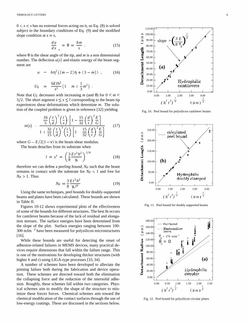
0 x shasnoexternalforcesactingon it, soEq. (8) is solvedsubjectto theboundaryconditionsof Eq. (9) andthemodifiedslopeconditionatx � s,
dudx '''' s
� θ � hms (15)
whereθ is theshearangleof thetip, andm is anondimensionalnumber. Thedeflectionu � x� andelasticenergy of thebeamseg-mentare
u � hη2 �0� m � 2 � η � � 3 � m �0� (16)
UE� 6EIh2
s3 � 1 � m � 13
m2 �- Note thatUE decreaseswith increasingm (andθ) for 0 $ m $3� 2. Theshortsegments $ x $ l correspondingto thebeamtipexperiencessheardeformationswhich determinem. The solu-tion of thecoupledproblemis givenin reference[32] yielding
m� s� � 165 � t
d ! 3 � ts ! 1 1 � 15
32 � dt ! 2 EG 2
1 � 3215 � t
d ! 3 � ts !31 1 � 1532 � dt ! 2 E
G 2 (17)
whereG � E � 2 � 1 � ν � is thebeamshearmodulus.Thebeamdetachesfrom its substratewhen
l � s� � � 38
Et3h2
γs ! 1" 4(18)
thereforewe candefinea peelingbound, NP suchthatthebeamremainsin contactwith the substratefor NP 1 and free forNP � 1. Thus
NP� 3
8Et3h2
γs l4(19)
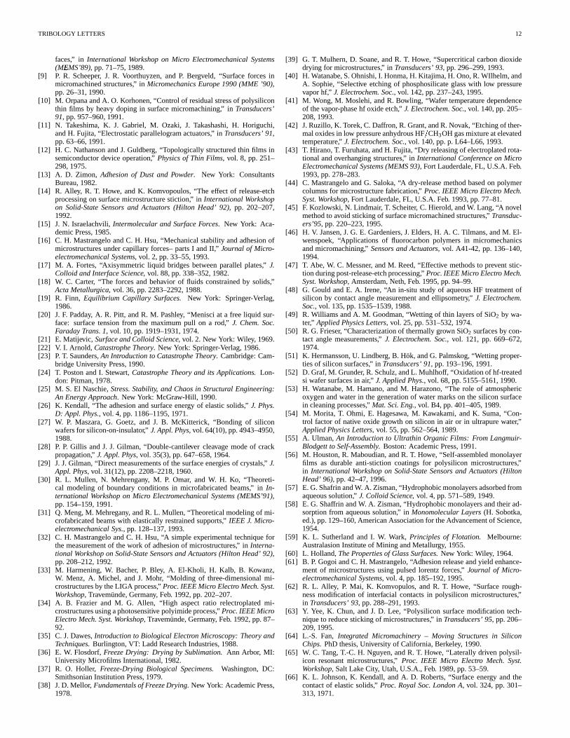
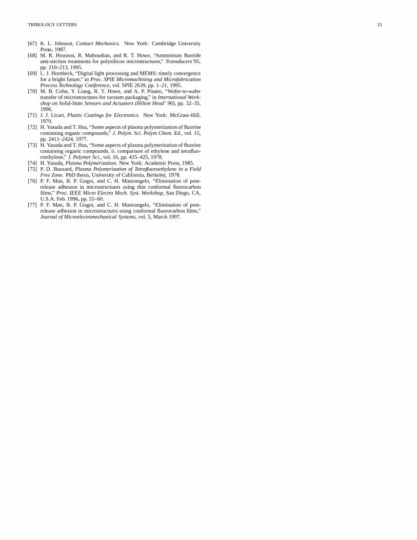
Usingthesametechniques,peelboundsfor doubly-supportedbeamsandplateshavebeencalculated.Theseboundsareshownin TableII.
Figures10-12shows experimentalplots of the effectivenessof someof theboundsfor differentstructures.Thebestfit occursfor cantileverbeamsbecauseof thelackof residualandelonga-tion stresses.The surfaceenergieshave beendeterminedfromthe slopeof the plot. Surfaceenergies rangingbetween100-300mJm& 2 havebeenmeasuredfor polysiliconmicrostructures[16].
While theseboundsare useful for detectingthe onset ofadhesion-relatedfailuresin MEMS devices,many practicalde-vicesrequiredimensionsthat fall within thefailurerange.Thisis oneof themotivationsfor developingthickerstructures(withhigherh andt) usingLIGA-type processes[33,34].
A numberof schemeshave beendevelopedto alleviate thepinning failure both during the fabricationand device opera-tion. Theseschemesaredirectedtoward both the eliminationthe collapsingforce and the reductionof the intersolid adhe-sion. Roughly, theseschemesfall within two categories.Phys-ical schemesaim to modify the shapeof the structureto min-imize theseforcesforces. Chemicalschemesaim toward thechemicalmodificationof thecontactsurfacesthroughtheuseoflow-energy coatings.Thesearediscussedin thesectionsbelow.
4 56 789 :5;6<5;=69 µ
m> ?
@�ACBEDGFIHKJMLONOLQPPGRTSMUVLONOWYXZWIDG[0.00
10.00
20.00
30.00
40.00
50.00
60.00
70.00
80.00
90.00
100.00
110.00
0.00 1.00 2.00 3.00 4.00
µ m\ ] 5
4h t2 3( )
1
4
(a)
1
4slope = (3
8Eγ )s
Fig. 10. Peelboundfor polysiliconcantilever beams
^`_a bcd`e_fag _fhad µ
mi j
k.lnmporq0s0t%uwvwuwxmpq0yIzMv l{x|vw}�~�sZ��mµ m� � 5
4h t2 3( )
1
4
0.00
50.00
100.00
150.00
200.00
250.00
0.00 1.00 2.00 3.00 4.00
x|}�vwxryKvw}�����msZ�0��v�zMq0yn�Km
(b)
Fig. 11. Peelboundfor doublysupportedbeams
µ m� � 5
4h t2 3( )
1
4
0.00
20.00
40.00
60.00
80.00
100.00
120.00
140.00
160.00
180.00
0.00 0.50 1.00 1.50 2.00 2.50
�*���p�����T���w�Q�Q����w�����n�Q�Z�(a)
γs = 270 mJm− 2
� �� ���`���� �¡¢`£¤
µm¥ ¦ §r¨©¨OªV«¬©®°¯°±²
ª ³´wµ¶¬©·¸³¹»º ª ª ³¼ ½«�¬O®°¯°±θ = 0c
Fig. 12. Peelboundfor polysiliconcircularplates

TRIBOLOGY LETTERS 7
TABLE II
APPROXIMATE PEEL NUMBERS FOR DIFFERENT MICROSTRUCTURES
Structure ApproximatePeelNumberscantileverbeam
38
Et3h2
γs l4
doublysupportedbeam � 128Eh2t3
5γsl4 !31 1 � 4σR l2
21Et2 � 2562205 � ht � 2 2
circularplate
403
Eh2 t3� 1 � ν2 � γsr4o ) 1 � 51� 1 � ν2 �
160σRr2
o
Et2 � 63200
h2
t2 +squareplate
186Eh2 t3� 1 � ν2 � γsw4 ) 1 � 27� 1 � ν2 �310
σRw2
Et2 � 1231
h2
t2 +IV. ELIMINATION OF COLLAPSING FORCE
A largenumberof adhesionfailuresoccurduringthefabrica-tion of thedevicesthemselves.Thesefailuresarerelatedto thecapillaryforcethatdevelopswhenthestructuresarereleasedbywet chemicaletches.Thecapillarypull forcecanbeeliminatedif the liquid phaseis not present.Several techniqueshave beenbaseduponthis idea.
It is worth noting thatbiologists[35] have struggledthroughthesameproblemsmuchearlier. It is well known thatcapillaryforcesare responsiblefor the collapseof fragile microscopicbiological specimens.Many methodshave beendevelopedtosolvethisproblem.Almostall of thesemethodshavebeenredis-coveredandappliedto MEMS structureswith variousdegreesof success.
A. Freeze-DryingMethods:
The rinsesolutioncanbe removed by freezingthe solutionandsublimation. This freeze-drying[36–38] techniquecanbeusedto eliminatethe capillarypull by freezingthe sampleandthenexposingit to aheatedvacuumenvironment.Thiswasfirstappliedto the releaseof MEMS devicesby Guckel andBurns[7]. A well known disadvantageof thefreeze-dryingmethodisthefact thattherinsesolutioncanundergoa significantvolumechange. This volume changecan createa stresssufficient todestroy the sample. The above authorsuseda cryoprotectantrinsesolutionconsistingof amixtureof methanolandwaterthatminimizedthevolumechange.A similarprocesswasdevelopedby Takeshimaet al. [11] by replacingtherinsesolutionthrougha gradualseriesof dilutionswith t-butyl alcoholwhich freezesat 25.6C¾ . Thefreeze-dryingtechniqueis now rarelyusedandhasbeenreplacedby the more successfulsupercriticaldryingtechniquedescribedbelow.
B. Supercritical Drying:
Anothermethodof eliminatingthecapillarypull is by theuseof supercriticaldrying techniques.In this technique,the rinsesolution is graduallyreplacedby liquid CO2 at elevatedpres-suresinsidea high-pressurechamber. Thesampleis thentakento thecritical point of CO2 wheretheinterfacebetweentheliq-uid andgasdoesnot exists. Thetechniqueis highly successfulwith nearly100%yields [39]. Commercialsupercriticaldryingequipmenthasbeenavailable for more than20 years[35] forsmallsamples,andlargescaleequipmentconstructionhasbeenplanned.The main difficulty with the techniqueresidesin thesafetyconsiderationsbecauseof theveryhigh( ¿ 72Atm) pres-suresrequiredto take thesamplesto thecritical point.
C. Dry Etching:
A numberof schemeshave beenproposedwhich arebasedon dry etchingof the sacrificial layer. This operationis oftendifficult if the sacrificial layer is silicon based(suchassilicondioxide) becauseit requiresstrongetchantsthat do not havegoodselectivities with respectto the suspendedelementmate-rial. Vapor-phaseHF etching[40] at elevatedtemperatures[41,42] hasbeenoftenusedfor this purposewith a high rateof at-tack of silicon nitride films. The structurecan also be easilyreleasedby plasmaetchingif thesacrificiallayeris silicon [43].
A moresuccessfulseriesof techniquesarebaseduponthere-placementof thesacrificiallayerwith aweakersolid thatcanbelaterremovedby aharmlessdry etching.Theseschemesinvolveprimarily thereplacementof sacrificiallayerswith plasticsthatcanbethenbeetchedusingO2 plasmaor ozonewhichareharm-lessto silicon-basedmaterials.Techniquesbasedupontheuseof p-xylylenesupports(Figure13-14)[44] havebeensuccessfulin releasingpolysiliconplatesthataslargeas3000 À 3000 À 1µm3. A techniquethat is baseduponthe replacementof the

TRIBOLOGY LETTERS 8
unreleasedpolysiliconmicrostructure
holes silicon dioxide
substrate
photoresist oxide undercut
substrate
aluminumparylene
substrate
oxygen plasma column removal
substrate
freepolysiliconmicrostructure
polymer columnssilicon dioxide
substrate
sacrificial oxide etchetch holes
substrate
Fig. 13. Constructionof polymersupportfeet that canbedry etchedthusre-leasingthesample.
Fig. 14. SEM of undersideof sacrificialp-xylylenesupports.Theplasticsup-portsareetchedusingoxygenplasma.
rinsesolutionwith resistthroughaseriesof dilutionswasdevel-opedby OrpanaandKorhonen[10]. Othertechniquesincludethereplacementof therinsesolutionwith monomersthatpoly-merizein ashorttimeaswell asplasma-polymerizedfluorinatedplastics[45,46].
D. Liquid BridgeCleavage:
The strongcapillary pull causesthe microstructurecollapsebecauseastherinsesolutionis removed,theliquid volumecon-centratesneartheweakestcentralpartof thesuspendedmember.Theimpactof thecapillarypull maythusbereducedif the liq-uid dropletis concentratednearthe anchorsinstead.Recently,Abe et al. [47] exploitedthis ideain a very ingeniousway. The
techniquemakesuseof a sharpcornerpatternedneartheweak-estpoint in the structure.As the liquid is removed,this cornerbreaksthe liquid bridgeinto two separatedropletsthat tendtoresidenearthe suspendedstructureanchors,wherethe impactof the capillary pull is minimal. Using theseidea, very longdouble-supportedbeamscanbefreelyreleasedwithout theneedof thetechniquesdescribedabove.
E. HydrophobicCoatings:
The capillary pull canbecomea pushif the contactangleismadelarger than90 ¾ . Thecontactangleof aqueoussolutionsonSiO2 andSi surfaceswasstudiedby severalresearchers[48–51]. Oxidizedsurfacesarehydrophilicwith contactanglesrang-ing from 0 � 39¾ dependingon the type of oxide andsurfacetreatment.Baresilicon surfacesobtainedby theremoval of na-tive oxide usingHF arehydrophobic.The hydrophobicityhasbeenattributedto possiblehydrogengroups[52] attachedto thesilicon. Contactangles[48] ashigh as78¾ have beenreported;however, thenativeoxideis known to regrow in bothwaterandwhenexposedto air [53,54]; thuscompletehydrophobicityisdifficult to achieve. In orderto accomplisha highercontactan-gle,a chemicalchangein thesurfaceof thesuspendedmemberis required.Recently, a numberof well-known [55] hydropho-bic self-assembledmonolayers(SAM) have beengrown on sil-icon surfaceswith successfulresults[14,56]. Theselayersarebasedon thesilanizationof siliconsurfaceswith organicgroupsby treatingthesurfacewith octadecyltrichlorosilane(OTS)pre-cursormolecule(C18H37SiCl3). Theprocedurefirst involvesthereplacementof theaqueousrinsewith anorganicsolventthougha seriesof dilution steps.TheSAM is next grown, andthenthesolvent is replacedby waterthroughthe reverseseriesof dilu-tions. Becausethe silanizedsurfaceshave a very high contactangle( ¿ 114¾ ), at thisstagethewaterrecedesfrom thesurfacesresultingin asamplethatemergesdry from therinse.Cantileverbeamsat leastas long as1000µm long weresuccessfullyre-leasedusingthis techniquewith beamsaslong as400µm pass-ing the“in-use” stictioncontacttest(Figure15).
Fig. 15. Sticking probability for cantilever beamsthat were given differenttreatments.
It may be possibleto eliminatethe complex seriesof dilu-tions if the hydrophobicfilm is formeddirectly in the aqueous

TRIBOLOGY LETTERS 9
solution. Autophobic films [57, 58] can be grown in silicondioxide substrateswhich areimmersedin aqueoussolutionsinthe presenceof a surfactant. Thesefilms canbe formedwhenweakly polar moleculeslike octadecylamine(C18H37NH3) aredissolved in water. Thesemoleculesattachto thesolid surfaceleaving the long hydrophobictail pointing toward the solution.Thesetypeof surfactantsarecommonlyusedfor theseparationof mineralpowdersby flotationtechniques[59,60].
F. ExternalReleaseForce:
This techniqueusesan external force to free a pinnedsus-pendedmember. Sampleswhich arepinnedto thesubstratecanoftenbefreedby theapplicationof asmallshearforce(oftenbyusinga probetip). A practicalimplementationof this schemehasbeendeveloped[61]. The techniqueinvolvestheconstruc-tion of awire ontopof thesuspendedmember. An upwardforcecanthenbegeneratedduringelectricaltestingby dischargingacapacitorthroughthe wire in the presenceof a magneticfieldasshown in Figure16. Thetechniquehasbeensuccessfullyap-
Nd−Fe−B permanent magnet
N
S
sample Vin
Rc
Rpot
Rb
Rin
C
Fig. 16. Releaseof pinnedmicrostructureby Lorentz force. The suspendedmemberis placedbetweenthepolesof apermanentmagnetandacapacitoris dischargedacrossit.
plied to the releaseof beamsandplatesasshown in Figure17with 100%yieldswith typical dischargesof 0.5µC.
Themaindifficulty with thetechniqueresidesin theconstruc-tion of the wire which may causeunnecessarywarpingof thesuspendedmember. Thetechniqueis alsousefulto electricallydeterminewhetheramicrostructureis pinnedor freedby exam-inationof thewire IV curve.
Mostof thesetechniques(with theexceptionof coatings)canonly eliminatethecapillarypull or its effectsduringits fabrica-tion process.After thesampleis packaged,if it is exposedto ahigh-humidityenvironmentor a shock,the pinningmay returnhencebecominga reliability issue.Thereforethesetechniquesareinsufficient to effectively eliminatethe adhesionfailurebutratherdelay it. A permanentsolution to the problemalso re-quiresadditionaltreatmentsthatattemptto reducetheintersolidadhesion.Thesearediscussedbelow.
V. REDUCTION OF INTERSOLID ADHESION
A permanenteliminationof theadhesionfailurerequiresthereductionof theintersolidsurfaceadhesion.Severaltechniqueshave beendevelopedtowardthis goal. Themainonesarelistedbelow.
Fig. 17. Array of doubly-supportedbeams(a) beforeand(b) after the appli-cationof thedischarge. The last two beamswerereleasedby theLorentzforce.
A. Useof TexturedSurfacesandPosts:
Theadhesionforcecanbereadilyreducedif thecontactareabetweenthe elasticmemberand the substrateis reduced. Inpractice,this canbeaccomplishedby texturing thecontactsur-face.Thismaybedonethroughthegenerationof a roughinter-face[62,63]. Yee[63] reportedan increasein the detachmentlengthof approximatelytwo by theoxidationanddry etchingofa polysiliconsupportingsurface.
The texturing can also be deliberatelyintroducedby con-structinga periodicarrayof small supportingpost,commonlyknown as“dimples”. Thesesupportsareconstructedby etchingsmallindentationsinto thesacrificiallayerbeforethedepositionof thesuspendedmemberasshown in Figure18causingthefor-mationof a protrusionin thestructurallayer(Figure19). Thismethodwasfirst usedby L. S. Fan [64] for theconstructionofa micromotor, andlaterappliedto combdrives[65]. Theforcerequiredto detacha semisphericaldimpleof radiusR is easilyshown to be[66,67]
F � � 3� 2� πγsR (20)
thus it becomeszero as R � 0. Furthermore,the dimple ap-proachbenefitsfrom thefactthatin generalthesuspendedmem-ber will be supportedby only threeposts(in much the same

TRIBOLOGY LETTERS 10
photoresist sacrificial layer
polysilicon
substrate
substrate
released plate
access hole
substrate
Fig. 18. Constructionof dimpleposts.
Fig. 19. SEMphotographof a typical dimpleonapolysiliconplate.
way that a tablewith irregular legs is only supportedby threeof them). This techniqueis very simplebut it suffers from twodrawbacks.
First, the dimple methodcannotbe appliedfor microstruc-tureswith flat surfacesasrequiredin many transducerdesigns.Second,theadhesionof thedimple is often larger thanthatan-ticipatedby Eq. (20) whendrying out the sample.This is be-lieved to be associatedwith the formation of an often visiblesolidbridgeof SiO2 asthewaterevaporates[53].
B. Low-EnergyMonolayerCoatings:
Thesecoatingsare the samehydrogenatedand OTS-typemonolayersdiscussedabove. If their intersolidadhesionenergyis sufficiently low, this option is very attractive sinceit elim-inatesboth failure originatingmechanisms.Recently, Houstonetal. [56] performedcontacttestsin siliconmicrostructureswithsurfacesthatwereterminatedwith hydrogenbonds,andcoatedwith OTS self-assembledmonolayers. Preliminary testssug-gestedthatcantileverbeamsaslong as1000µm-longexhibitedabout50 % sticking probability on OTS-coatedsamplesafterthey arebroughtin contactwith thesubstrate( Figure15). Thesefilms havebeenreportedto show anextremelylow effectivead-
hesionenergy (3 µJm& 2).The main difficulty associatedwith many of thesefilms is
their extremefragility. Becausethe SAM films areextremelythin ( ¿ 2.5 nm), they have a high tendency to degradeat ele-vatedtemperatures,asshown in Figure21. [56]. Theagingbe-havior of hydrogenterminatedsurfaceshasalsobeenobservedby Houstonet al. [68] as shown in Figure 20 indicating thatthesesurfaceschemicallyreactwith contaminantsover time.
Fig. 20. Degradationof low-energy coatingformedby NH4F treatment.Theplot indicatesthepassivatingmonolayerdegradesafter100hoursof expo-sureto atmosphericconditions.
Fig. 21. Degradationof thecontactanglein self-assembledOTS coatingsex-posed5 minutesto variousenvironments.
Thesefilms however remaineffective insidesealed,controlledenvironmentsat thermalequilibriumwheredegradingreactionscannottake place,andany vaporizationis henceforthfollowedby aredeposition.
Similar monolayerfilms are currently used in sealedde-formablemirror displaysunderthis strictly controlledenviron-ment[69]. This inherentneedfor a suitablepackagingtechnol-ogy hasbecomea driver for thedevelopmentof micropackagesin MEMS devices[70].
C. FluorinatedCoatings:
Fluorinatedhydrocarboncoatingsconsistingof CFx chainshavevery low surfaceenergies;hencethey arelikely candidatescoatingsfor thereductionof intersolidadhesion.TFE-like lay-erscanbegrown in many differentways[71]. A commonway

TRIBOLOGY LETTERS 11
to grow thesefilms is by plasmapolymerization[72–74]. Oftenthegrowth of thesefilms is highly directionalwith mostof thegrowth occurringin thesurfacesexposedto theplasma[46]. Inorderfor thesefilms to beeffective,thefilm mustbecapableofgrowth underacoveredsurface.
Fluorinatedfilms canalsobegrown atamuchreducedrateinzoneswhich arenot directlyexposedto theplasma[75]. In thisregime,thedepositionrateis a diffusion-limitedprocesswhichis not subjectto therapiddecayof theplasmadensityresultingin amuchmoreuniformdeposition.This ideahasbeenrecentlyexploitedby Manetal. [76,77] to depositnearconformalTFE-like films in silicon microstructures.Using this technique,thedepositiontakesplaceinsidea Faradaycagethat preventstheplasmafrom reachingthesampleasshown in Figure22. These
PlasmaSample
Spacer
Wire mesh C4F10
Fig. 22. Setupusedfor depositionof TFE-like films
40Á
60Â
80Ã
1000.5Ä0.6Ä0.7Ä0.8Ä0.9Ä1.0Å1.1Å
x (um)
NO
RM
AL
IZE
D T
EF
LO
N D
EP
OS
ITIO
N
50 100 150
1.1
1.0
0.9Æ0.8Æ0.7Æ0.6Æ0.5Æ X
x (um)
X
Fig.23. Uniformity of TFE-likefilms ontheundersideof suspendedplates.Thefront of theplatehasapproximatelytwice thethicknessastheunderside.
fluorinatedfilms canbequitethick ( � 20nm)hencedurableandhaveacontactangleof about108 ¾ .
Periodicwearandtemperaturetestshave beenperformedinthesefilms asshown in Figure24.Theresultspredictaprojectedmeantime to failure(determinedby a lossin thehydrophobic-ity) greaterthan10 yearsat 150 ¾ C in atmosphericconditions.The films remainhydrophobiceven at very high temperaturesanddisplaylittle wearevenafter107 contactcycles.
Of all theaboveadhesionpreventionmethods,thelow-energycoatingsare the most effective and reliable. The monolayertechniqueis especiallyattractive in thesensethat it solvesbothcapillarypull andadhesionproblemswith only oneapplication,but it requiresasealedpackageto maintainthelongtermmono-layerintegrity. Thickerfilms aremorerobustandcansurviveat-mosphericconditionsfor many yearsbut theserequiretheuseofa complementarytechniqueto eliminatethe capillary pull dur-
Time to failure (hours)3 310 110 210
1.2
1.4
1.6
1.8
2.0
2.2Film thickness ( nm )
12 28 41
1000
/ Tem
pera
ture
( K
)
0
Fig. 24. Degradationof TFE-like plasmapolymerizedcoatingsunderatmo-sphericconditionsat different temperatures.Thesefilms remainon thesamplefor many years.
ing thedevice fabrication.Perhapsthebestsolutionis a combi-nationof bothtechniques.
Thethicknessof thefilm is not only determinedby thedura-bility desiredbut alsoby how it affectsthedevice structure.Incaseswherethe structuremusthave high quality factor, a thinlayer is desired;while otherstructuresmay be moresuitedtothicker, strongerfilms.
VI . SUMMARY
This paperreviews thesourcescausingadhesion-relatedfail-ures in microelectromechanicalsystems. Thesefailures arecausedby thefactthatMEMS devicesareextremelysusceptibleto surfaceforcesbecausethey arevery fragile andin verycloseproximity to their substrateshencecausingsuspendedelasticmembersto stick to theirsubstrates.Thefailureoriginatesfromthepresenceof acollapsingforcewhichmaybeexternalor orig-inatedby capillaryforceswhenthesuspendedpartis exposedtoa liquid. this is then followed by a strongintersolidadhesioncapableof overcomingtheelasticmemberrestoringforce. Thebehavior of themicrostructureunderthesetwo phenomenahasbeenexamined.Severalpracticaltechniquesfor theeliminationof thecollapsingforceandtheintersolidadhesionarediscussed.
REFERENCES
[1] K. Chau,C. Fung,P. R. Harris,andG. Dahrooge,“A verstilepolysilicondiaphragmpressuresensorchip,” in Int. ElectronDevicesMeeting, (IEDM91), pp.695–697,1991.
[2] D. W. Burns,Micromechanicsof IntegratedSensors andthePlanar Pro-cessedPressureTransducer. PhDthesis,Universityof Winsconsin,Madi-son,1988.
[3] J. M. Lysko, E. Stolarski,andR. S. Jachowicz, “Capacitive silicon pres-suresensorbasedon theone-sidewaferprocessing,” in Transducers’ 91,pp.685–688,1991.
[4] J. T. Kung and H.-S. Lee, “An integratedair-gap capacitorprocessforsensorapplications,” in Transducers’ 91, pp.312–314,1991.
[5] W. Yun, R. T. Howe, andP. R. Gray, “Surfacemicromachined,digitallyforce-balancedaccelerometerwith integratedCMOSdetectioncircuitry,”in InternationalWorkshopon Solid-StateSensors and Actuators (HiltonHead’ 92), pp.126–131,1992.
[6] L. Ristic, R. Gutteridge,B. Dunn, D. Mietus, andP. Bennett,“Surfacemicromachinedpolysiliconaccelerometer,” in InternationalWorkshoponSolid-StateSensors andActuators (Hilton Head’92), pp.118–121,1992.
[7] H. Guckel and D. W. Burns, “Fabricationof micromechanicaldevicesfrom polysilicon films with smoothsurfaces,” Sensors and Actuators,vol. 20,pp.117–122,1989.
[8] H. Guckel, J. J. Sniegoeski, and T. R. Christenson,“Advancesin pro-cessingtechniquesfor silicon micromechanicaldeviceswith smoothsur-
TRIBOLOGY LETTERS 12
faces,” in International Workshopon Micro Electromechanical Systems(MEMS’89)Ç , pp.71–75,1989.
[9] P. R. Scheeper, J. R. Voorthuyzen,and P. Bergveld, “Surfaceforcesinmicromachinedstructures,” in MicromechanicsEurope1990(MME ’90),pp.26–31,1990.
[10] M. OrpanaandA. O. Korhonen,“Control of residualstressof polysiliconthin films by heavy dopingin surfacemicromachining,” in Transducers’91, pp.957–960,1991.
[11] N. Takeshima,K. J. Gabriel, M. Ozaki, J. Takashashi,H. Horiguchi,andH. Fujita, “Electrostaticparallelogramactuators,” in Transducers’ 91,pp.63–66,1991.
[12] H. C. NathansonandJ. Guldberg, “Topologicallystructuredthin films insemiconductordevice operation,” Physicsof Thin Films, vol. 8, pp. 251–298,1975.
[13] A. D. Zimon, Adhesionof Dust and Powder. New York: ConsultantsBureau,1982.
[14] R. Alley, R. T. Howe, andK. Komvopoulos,“The effect of release-etchprocessingon surfacemicrostructurestiction,” in InternationalWorkshopon Solid-StateSensors and Actuators (Hilton Head’ 92), pp. 202–207,1992.
[15] J. N. Israelachvili,Intermolecularand SurfaceForces. New York: Aca-demicPress,1985.
[16] C. H. MastrangeloandC. H. Hsu, “Mechanicalstability andadhesionofmicrostructuresundercapillary forces–partsI andII,” Journal of Micro-electromechanical Systems, vol. 2, pp.33–55,1993.
[17] M. A. Fortes,“Axisymmetric liquid bridgesbetweenparallel plates,” J.Colloid andInterfaceScience, vol. 88,pp.338–352,1982.
[18] W. C. Carter, “The forcesandbehavior of fluids constrainedby solids,”ActaMetallurgica, vol. 36,pp.2283–2292,1988.
[19] R. Finn, Equilibrium Capillary Surfaces. New York: Springer-Verlag,1986.
[20] J. F. Padday, A. R. Pitt, andR. M. Pashley, “Menisci at a free liquid sur-face: surfacetensionfrom the maximumpull on a rod,” J. Chem.Soc.FaradayTrans.1, vol. 10,pp.1919–1931,1974.
[21] E. Matijevic, SurfaceandColloid Science, vol. 2. New York: Wiley, 1969.[22] V. I. Arnold, CatastropheTheory. New York: Springer-Verlag,1986.[23] P. T. Saunders,AnIntroductionto CatastropheTheory. Cambridge:Cam-
bridgeUniversityPress,1990.[24] T. PostonandI. Stewart, CatastropheTheoryand its Applications. Lon-
don: Pitman,1978.[25] M. S. El Naschie,Stress.Stability, andChaosin Structural Engineering:
An EnergyApproach. New York: McGraw-Hill, 1990.[26] K. Kendall,“The adhesionandsurfaceenergy of elasticsolids,” J. Phys.
D: Appl.Phys., vol. 4, pp.1186–1195,1971.[27] W. P. Maszara,G. Goetz, and J. B. McKitterick, “Bonding of silicon
wafersfor silicon-on-insulator,” J. Appl.Phys, vol. 64(10),pp.4943–4950,1988.
[28] P. P. Gillis andJ. J. Gilman, “Double-cantilever cleavagemodeof crackpropagation,” J. Appl.Phys, vol. 35(3),pp.647–658,1964.
[29] J.J.Gilman,“Direct measurementsof thesurfaceenergiesof crystals,” J.Appl.Phys, vol. 31(12),pp.2208–2218,1960.
[30] R. L. Mullen, N. Mehrengany, M. P. Omar, and W. H. Ko, “Theoreti-cal modelingof boundaryconditionsin microfabricatedbeams,” in In-ternationalWorkshopon Micro Electromechanical Systems(MEMS’91),pp.154–159,1991.
[31] Q. Meng,M. Mehregany, andR. L. Mullen, “Theoreticalmodelingof mi-crofabricatedbeamswith elasticallyrestrainedsupports,” IEEE J. Micro-electromechanical Sys., pp.128–137,1993.
[32] C. H. MastrangeloandC. H. Hsu, “A simpleexperimentaltechniqueforthemeasurementof thework of adhesionof microstructures,” in Interna-tional Workshopon Solid-StateSensors andActuators (Hilton Head’ 92),pp.208–212,1992.
[33] M. Harmening,W. Bacher, P. Bley, A. El-Kholi, H. Kalb, B. Kowanz,W. Menz, A. Michel, and J. Mohr, “Molding of three-dimensionalmi-crostructuresby theLIGA process,” Proc.IEEEMicro Electro Mech. Syst.Workshop,Travemunde,Germany, Feb. 1992,pp.202–207.
[34] A. B. Frazier and M. G. Allen, “High aspectratio relectroplatedmi-crostructuresusingaphotosensitivepolyimideprocess,” Proc.IEEEMicroElectro Mech. Syst.Workshop,Travemunde,Germany, Feb. 1992,pp.87–92.
[35] C. J.Dawes,Introductionto Biological Electron Microscopy:TheoryandTechniques. Burlington,VT: LaddResearchIndustries,1988.
[36] E. W. Flosdorf,FreezeDrying: Drying by Sublimation. Ann Arbor, MI:UniversityMicrofilms International,1982.
[37] R. O. Holler, Freeze-DryingBiological Specimens. Washington,DC:SmithsonianInstitutionPress,1979.
[38] J.D. Mellor, Fundamentalsof FreezeDrying. New York: AcademicPress,1978.
[39] G. T. Mulhern,D. Soane,andR. T. Howe, “Supercriticalcarbondioxidedrying for microstructures,” in Transducers’ 93, pp.296–299,1993.
[40] H. Watanabe,S.Ohnishi,I. Honma,H. Kitajima,H. Ono,R.WIlhelm,andA. Sophie,“Selective etchingof phosphosilicateglasswith low pressurevaporhf,” J. Electrochem.Soc., vol. 142,pp.237–243,1995.
[41] M. Wong,M. Moslehi,andR. Bowling, “Wafer temperaturedependenceof thevapor-phasehf oxideetch,” J. Electrochem.Soc., vol. 140,pp.205–208,1993.
[42] J.Ruzillo, K. Torek,C. Daffron, R. Grant,andR. Novak,“Etchingof ther-maloxidesin low pressureanhydrousHF È CH3OH gasmixtureatelevatedtemperature,” J. Electrochem.Soc., vol. 140,pp.p. L64–L66,1993.
[43] T. Hirano,T. Furuhata,andH. Fujita, “Dry releasingof electroplatedrota-tional andoverhangingstructures,” in InternationalConferenceon MicroElectromechanicalSystems(MEMS93),Fort Lauderdale,FL, U.S.A.Feb.1993,pp.278–283.
[44] C. MastrangeloandG. Saloka,“A dry-releasemethodbasedon polymercolumnsfor microstructurefabrication,” Proc. IEEE Micro Electro Mech.Syst.Workshop,Fort Lauderdale,FL, U.S.A.Feb. 1993,pp.77–81.
[45] F. Kozlowski, N. Lindmair, T. Scheiter, C. Hierold,andW. Lang,“A novelmethodto avoid stickingof surfacemicromachinedstructures,” Transduc-ers’95, pp.220–223,1995.
[46] H. V. Jansen,J.G. E. Gardeniers,J.Elders,H. A. C. Tilmans,andM. El-wenspoek,“Applications of fluorocarbonpolymers in micromechanicsandmicromachining,” Sensors andActuators, vol. A41-42,pp. 136–140,1994.
[47] T. Abe, W. C. Messner, andM. Reed,“Effective methodsto prevent stic-tion duringpost-release-etchprocessing,” Proc.IEEEMicro Electro Mech.Syst.Workshop,Amsterdam,Neth,Feb. 1995,pp.94–99.
[48] G. Gould andE. A. Irene,“An in-situ studyof aqueousHF treatmentofsilicon by contactanglemeasurementandellipsometry,” J. Electrochem.Soc., vol. 135,pp.1535–1539,1988.
[49] R. Williams andA. M. Goodman,“Wettingof thin layersof SiO2 by wa-ter,” AppliedPhysicsLetters, vol. 25,pp.531–532,1974.
[50] R. G. Frieser, “Characterizationof thermallygrown SiO2 surfacesby con-tact anglemeasurements,” J. Electrochem.Soc., vol. 121, pp. 669–672,1974.
[51] K. Hermansson,U. Lindberg, B. Hok, andG. Palmskog, “Wettingproper-tiesof silicon surfaces,” in Transducers’ 91, pp.193–196,1991.
[52] D. Graf,M. Grunder, R. Schulz,andL. Muhlhoff, “Oxidationof hf-treatedsi wafersurfacesin air,” J. AppliedPhys., vol. 68,pp.5155–5161,1990.
[53] H. Watanabe,M. Hamano,andM. Harazono,“The role of atmosphericoxygenandwaterin thegenerationof watermarkson thesilicon surfacein cleaningprocesses,” Mat. Sci.Eng., vol. B4, pp.401–405,1989.
[54] M. Morita, T. Ohmi, E. Hagesawa, M. Kawakami,andK. Suma,“Con-trol factorof native oxidegrowth on silicon in air or in ultrapurewater,”AppliedPhysicsLetters, vol. 55,pp.562–564,1989.
[55] A. Ulman,An Introductionto Ultrathin OrganicFilms: FromLangmuir-Blodgett to Self-Assembly. Boston:AcademicPress,1991.
[56] M. Houston,R. Maboudian,andR. T. Howe, “Self-assembledmonolayerfilms as durableanti-stiction coatingsfor polysilicon microstructures,”in InternationalWorkshopon Solid-StateSensors and Actuators (HiltonHead’ 96), pp.42–47,1996.
[57] E.G.ShafrinandW. A. Zisman,“Hydrophobicmonolayersadsorbedfromaqueoussolution,” J. Colloid Science, vol. 4, pp.571–589,1949.
[58] E. G. Shaffrin andW. A. Zisman,“Hydrophobicmonolayersandtheirad-sorptionfrom aqueoussolution,” in MonomolecularLayers (H. Sobotka,ed.),pp.129–160,AmericanAssociationfor theAdvancementof Science,1954.
[59] K. L. Sutherlandand I. W. Wark, Principles of Flotation. Melbourne:AustralasionInstituteof Mining andMetallurgy, 1955.
[60] L. Holland,ThePropertiesof GlassSurfaces. New York: Wiley, 1964.[61] B. P. GogoiandC. H. Mastrangelo,“Adhesionreleaseandyield enhance-
ment of microstructuresusingpulsedlorentz forces,” Journal of Micro-electromechanicalSystems, vol. 4, pp.185–192,1995.
[62] R. L. Alley, P. Mai, K. Komvopulos,and R. T. Howe, “Surfacerough-nessmodificationof interfacial contactsin polysilicon microstructures,”in Transducers’ 93, pp.288–291,1993.
[63] Y. Yee,K. Chun,andJ. D. Lee, “Polysilicon surfacemodificationtech-niqueto reducestickingof microstructures,” in Transducers’ 95, pp.206–209,1995.
[64] L.-S. Fan, Integrated Micromachinery – Moving Structures in SiliconChips. PhDthesis,Universityof California,Berkeley, 1990.
[65] W. C. Tang,T.-C. H. Nguyen,andR. T. Howe, “Laterally drivenpolysil-icon resonantmicrostructures,” Proc. IEEE Micro Electro Mech. Syst.Workshop,SaltLakeCity, Utah,U.S.A.,Feb. 1989,pp.53–59.
[66] K. L. Johnson,K. Kendall,andA. D. Roberts,“Surfaceenergy andthecontactof elasticsolids,” Proc. RoyalSoc.LondonA, vol. 324,pp. 301–313,1971.
TRIBOLOGY LETTERS 13
[67] K. L. Johnson,ContactMechanics. New York: CambridgeUniversityPress,É 1987.
[68] M. R. Houston,R. Maboudian,and R. T. Howe, “Ammonium fluorideanti-stictiontreatmentsfor polysilicon microstructures,” Transducers’95,pp.210–213,1995.
[69] L. J.Hornbeck,“Digital light processingandMEMS: timely convergencefor a bright future,” in Proc. SPIEMicromachining andMicrofabricationProcessTechnology Conference, vol. SPIE2639,pp.1–21,1995.
[70] M. B. Cohn, Y. Liang, R. T. Howe, and A. P. Pisano,“Wafer-to-wafertransferof microstructuresfor vacuumpackaging,” in InternationalWork-shopon Solid-StateSensors andActuators (Hilton Head’ 96), pp. 32–35,1996.
[71] J. J. Licari, Plastic Coatingsfor Electronics. New York: McGraw-Hill,1970.
[72] H. YasudaandT. Hsu,“Someaspectsof plasmapolymerizationof fluorinecontainingorganiccompounds,” J. Polym.Sci.PolymChem.Ed., vol. 15,pp.2411–2424,1977.
[73] H. YasudaandT. Hsu,“Someaspectsof plasmapolymerizationof fluorinecontainingorganiccompounds.ii. comparisonof ethyleneandtetrafluo-roethylene,” J. PolymerSci., vol. 16,pp.415–425,1978.
[74] H. Yasuda,PlasmaPolymerization. New York: AcademicPress,1985.[75] P. D. Buzzard,PlasmaPolymerizationof Tetrafluoroethylenein a Field
FreeZone. PhDthesis,Universityof California,Berkeley, 1978.[76] P. F. Man, B. P. Gogoi, and C. H. Mastrangelo,“Elimination of post-
releaseadhesionin microstructuresusing thin conformal fluorocarbonfilms,” Proc. IEEE Micro Electro Mech. Syst.Workshop,SanDiego, CA,U.S.A.Feb. 1996,pp.55–60.
[77] P. F. Man, B. P. Gogoi, and C. H. Mastrangelo,“Elimination of post-releaseadhesionin microstructuresusingconformalfluorocarbonfilms,”Journal of Microelectromechanical Systems, vol. 5, March1997.