The Canoe Ridge Natural Gas Storage Project - pnnl.gov stream systems, ... (situated between the...
34
PNNL-14298 The Canoe Ridge Natural Gas Storage Project S. P. Reidel F. A. Spane V. G. Johnson May 2003 Prepared for the U.S. Department of Energy under Contract DE-AC06-76RL01830
Transcript of The Canoe Ridge Natural Gas Storage Project - pnnl.gov stream systems, ... (situated between the...
PNNL-14298
The Canoe Ridge Natural Gas Storage Project S. P. Reidel F. A. Spane V. G. Johnson May 2003 Prepared for the U.S. Department of Energy under Contract DE-AC06-76RL01830
DISCLAIMER This report was prepared as an account of work sponsored by an agency of the United States Government. Neither the United States Government nor any agency thereof, nor Battelle Memorial Institute, nor any of their employees, makes any warranty, express or implied, or assumes any legal liability or responsibility for the accuracy, completeness, or usefulness of any information, apparatus, product, or process disclosed, or represents that its use would not infringe privately owned rights. Reference herein to any specific commercial product, process, or service by trade name, trademark, manufacturer, or otherwise does not necessarily constitute or imply its endorsement, recommendation, or favoring by the United States Government or any agency thereof, or Battelle Memorial Institute. The views and opinions of authors expressed herein do not necessarily state or reflect those of the United States Government or any agency thereof.
PACIFIC NORTHWEST NATIONAL LABORATORY operated by BATTELLE
for the UNITED STATES DEPARTMENT OF ENERGY
under Contract DE-AC06-76RL01830
Printed in the United States of America
Available to DOE and DOE contractors from the Office of Scientific and Technical Information,
P.O. Box 62, Oak Ridge, TN 37831-0062; ph: (865) 576-8401 fax: (865) 576-5728
email: [email protected]
Available to the public from the National Technical Information Service, U.S. Department of Commerce, 5285 Port Royal Rd., Springfield, VA 22161
ph: (800) 553-6847 fax: (703) 605-6900
email: [email protected] online ordering: http://www.ntis.gov/ordering.htm
This document was printed on recycled paper. (8/00)
PNNL-14298
The Canoe Ridge Natural Gas Storage Project S. P. Reidel F. A. Spane V. G. Johnson May 2003 Prepared for the U.S. Department of Energy National Energy Technology Laboratory 626 Cochran Mill Road Pittsburgh, Pennsylvania 15236 under Contract DE-AC06-76RL01830 Pacific Northwest National Laboratory Richland, Washington 99352
iii
Summary
In 1999, the Pacific Gas and Electric Gas Transmission Northwest (GTN) drilled a borehole to investigate the feasibility of developing a natural gas-storage facility in a structural dome formed in Columbia River basalts in the Columbia Basin of south-central Washington State. The proposed aquifer storage facility will be an unconventional one where natural gas will be initially injected (and later retrieved) in one or multiple pervious horizons (interflow zones) that are confined between deep (>700 meters) basalt flows of the Columbia River Basalt Group. This report summarizes the results of joint investigations on that feasibility study by GTN and the U.S. Department of Energy.
v
Contents
Summary ................................................................................................................................................ iii
1.0 Introduction ................................................................................................................................... 1
2.0 Site Location.................................................................................................................................. 1
2.1 Surface Geology.................................................................................................................... 2
2.2 Surface Structure ................................................................................................................... 6
2.3 Hydrogeologic Conditions and Issues................................................................................... 6
3.0 Exploratory Borehole #1 ............................................................................................................... 8
3.1 Borehole History ................................................................................................................... 8
3.2 Borehole Geology ................................................................................................................. 9
3.2.1 Subsurface Stratigraphy ............................................................................................. 9 3.2.2 Faulting and Fracture Zones....................................................................................... 10
4.0 Hydrologic Characterization.......................................................................................................... 10
4.1 General Testing Strategy....................................................................................................... 11
4.2 Regional Hydrologic Information ......................................................................................... 12
4.2.1 Regional Hydraulic Properties ................................................................................... 13 4.2.2 Regional Vertical Hydraulic Head Conditions........................................................... 14 4.2.3 Regional Hydrochemistry .......................................................................................... 15
4.3 Canoe Ridge Characterization Test Results .......................................................................... 16
4.3.1 Hydraulic Properties................................................................................................... 16 4.3.2 Hydraulic Head .......................................................................................................... 19 4.3.3 Hydrochemistry.......................................................................................................... 21
5.0 Summary and Conclusions ............................................................................................................ 24
6.0 Hydrologic Test Recommendations .............................................................................................. 25
7.0 References ..................................................................................................................................... 26
vi
Figures 1 Natural Gas Supply Lines Serving Eastern Washington and Eastern Oregon ................................ 2 2 Location Map Showing Canoe Ridge and Natural Gas Transmission Lines .................................. 3 3 Anticlinal Ridges of the Yakima Fold Belt ..................................................................................... 4 4 Stratigraphic Nomenclature of the Columbia River Basalt Group.................................................. 5 5 Typical Internal Features of a Columbia River Basalt Group Flow................................................ 7 6 Hydraulic Conductivity for CRBG Formation Flow Tops.............................................................. 14 7 Air-Lift Pumping Test Constant-Drawdown Analysis for Grande Ronde, Zone 1 ......................... 17 8 Air-Lift Pumping Test Pressure Recovery Analysis for Grande Ronde Zone #1 ........................... 18
Tables 1 Constant-Drawdown Air-Lift Test Analysis Summary, Canoe Ridge Borehole #1........................ 17 2 Comparison of Analysis Results for Various Analytical Methods, for Hydrologic Tests
Conducted Within Canoe Ridge Borehole #1 ................................................................................. 19 3 Observed Hydraulic Measurements for Canoe Ridge Borehole #1 Test Intervals.......................... 20 4 Field Hydrochemical Measurement Results.................................................................................... 22
1
1.0 Introduction
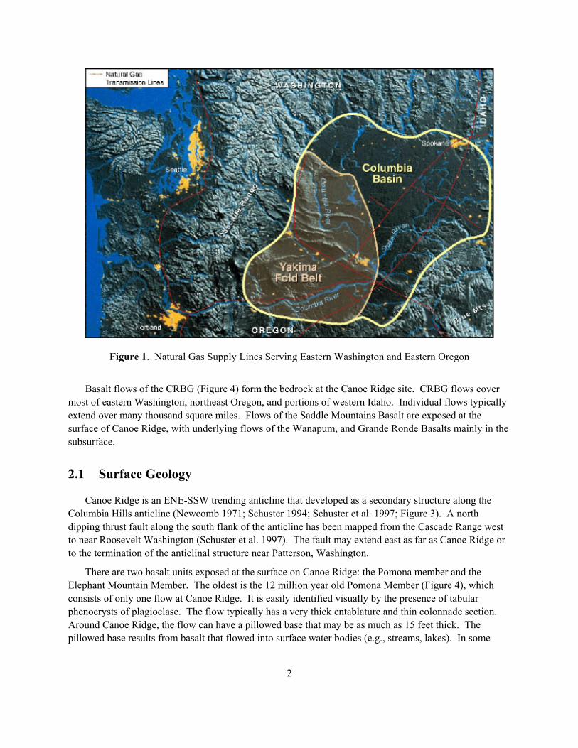
The current power generation capacity within the Pacific Northwest region is primarily supplied by hydroelectric projects (67%), with lesser capacity provided by various thermal (23%), and nuclear plants (10%), as reported in BPA (2000). Given the maximum state of hydroelectric project development on major stream systems, increases to the region�s future power generating capacity will have to examine non-hydroelectric sources. A viable, non-nuclear alternative solution to meet future power needs in the Pacific Northwest is the construction of natural gas fired power plants. A major requirement for utili-zation of the natural gas option, however, is the availability of sufficient natural gas storage capacity during non-power peaking and low heating demand periods. While a number of regional natural gas supply lines transverse the northwest (Figure 1), no significant storage capacity has been developed within the region. The occurrence of thick sequences of Columbia River basalts within the Columbia Basin (situated between the Cascade Range and the Rocky Mountains), however, offers a high potential for developing new, unconventional subsurface natural gas storage.
Pacific Gas and Electric Gas Transmission Northwest (GTN) is investigating the feasibility of developing a natural gas-storage facility in Columbia River basalts that form a structural dome in the Columbia Basin of south-central Washington State. The proposed aquifer storage facility will be an unconventional one where natural gas will be initially injected (and later retrieved) in one or multiple pervious horizons (interflow zones) that are confined between deep (>700 meters) basalt flows of the Columbia River Basalt Group (CRBG). Methodologies and techniques for characterizing and evaluating the Columbia River basalt for natural gas storage have been previously reported by the Pacific Northwest National Laboratory (Reidel et al. 2002), as part of the National Energy Technology Laboratories� ongoing research into unconventional natural gas storage facilities. This report summarizes the first phase of site characterization activity at the Canoe Ridge site. Details of the methodologies and testing techniques used at Canoe Ridge are described in Reidel et al. (2002).
2.0 Site Location
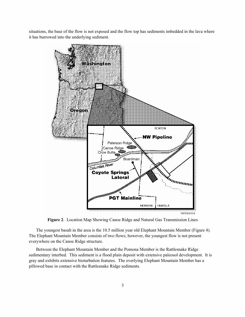
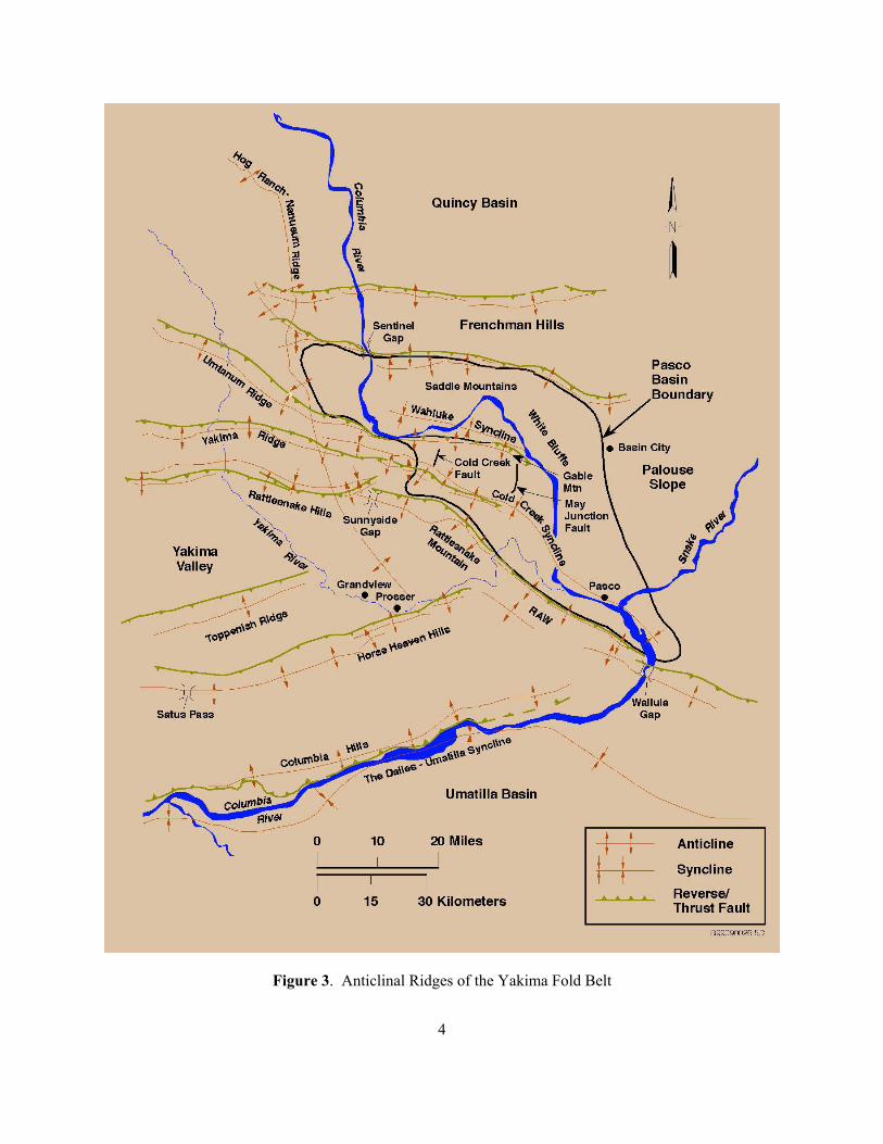
The proposed Canoe Ridge natural gas storage site is located along the Columbia Hills anticline (Figures 2 and 3) in south-central Washington, just north of the Oregon border. The Columbia Hills anticline is typical of other similar structures within the Yakima Fold Belt, in that it is a narrow, asymmetrical anticline with a south vergence that extends about 100 kilometers along the Washington-Oregon border.
Canoe Ridge occurs along the eastern portion of the Columbia Hills anticline, which terminates about 20 kilometers to the east. Canoe Ridge it is a topographic and structural dome that trends ENE-WSW and covers approximately 7 square miles. Structure relief increases on the Columbia Hills to the west and decreases to the east. The favorable potential for fluid storage within deep basalts in this structural location has been recognized in a number of earlier investigations and was considered by the U.S. Geological Survey as a potential pumped-storage reservoir for groundwater (Newcomb 1971).
2
Figure 1. Natural Gas Supply Lines Serving Eastern Washington and Eastern Oregon
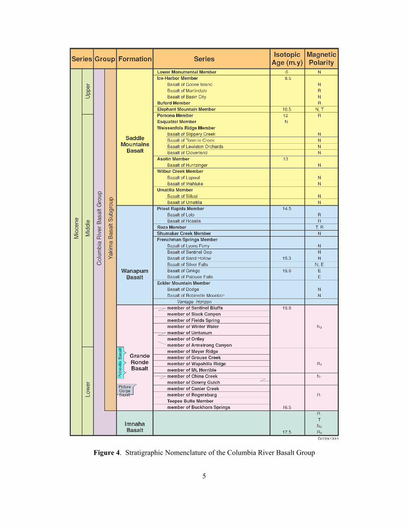
Basalt flows of the CRBG (Figure 4) form the bedrock at the Canoe Ridge site. CRBG flows cover most of eastern Washington, northeast Oregon, and portions of western Idaho. Individual flows typically extend over many thousand square miles. Flows of the Saddle Mountains Basalt are exposed at the surface of Canoe Ridge, with underlying flows of the Wanapum, and Grande Ronde Basalts mainly in the subsurface.
2.1 Surface Geology
Canoe Ridge is an ENE-SSW trending anticline that developed as a secondary structure along the Columbia Hills anticline (Newcomb 1971; Schuster 1994; Schuster et al. 1997; Figure 3). A north dipping thrust fault along the south flank of the anticline has been mapped from the Cascade Range west to near Roosevelt Washington (Schuster et al. 1997). The fault may extend east as far as Canoe Ridge or to the termination of the anticlinal structure near Patterson, Washington.
There are two basalt units exposed at the surface on Canoe Ridge: the Pomona member and the Elephant Mountain Member. The oldest is the 12 million year old Pomona Member (Figure 4), which consists of only one flow at Canoe Ridge. It is easily identified visually by the presence of tabular phenocrysts of plagioclase. The flow typically has a very thick entablature and thin colonnade section. Around Canoe Ridge, the flow can have a pillowed base that may be as much as 15 feet thick. The pillowed base results from basalt that flowed into surface water bodies (e.g., streams, lakes). In some
3
situations, the base of the flow is not exposed and the flow top has sediments imbedded in the lava where it has burrowed into the underlying sediment.
Figure 2. Location Map Showing Canoe Ridge and Natural Gas Transmission Lines
The youngest basalt in the area is the 10.5 million year old Elephant Mountain Member (Figure 4). The Elephant Mountain Member consists of two flows; however, the youngest flow is not present everywhere on the Canoe Ridge structure.
Between the Elephant Mountain Member and the Pomona Member is the Rattlesnake Ridge sedimentary interbed. This sediment is a flood plain deposit with extensive paleosol development. It is gray and exhibits extensive bioturbation features. The overlying Elephant Mountain Member has a pillowed base in contact with the Rattlesnake Ridge sediments.
4
Figure 3. Anticlinal Ridges of the Yakima Fold Belt
5
Figure 4. Stratigraphic Nomenclature of the Columbia River Basalt Group
6
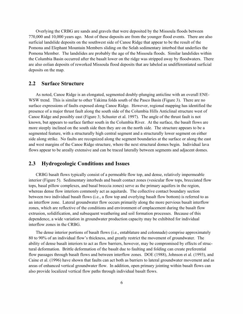
Overlying the CRBG are sands and gravels that were deposited by the Missoula floods between 770,000 and 10,000 years ago. Most of these deposits are from the younger flood events. There are also surficial landslide deposits on the southwest side of Canoe Ridge that appear to be the result of the Pomona and Elephant Mountain Members sliding on the Selah sedimentary interbed that underlies the Pomona Member. The landslides are probably the age of the Missoula floods. Similar landslides within the Columbia Basin occurred after the basalt lower on the ridge was stripped away by floodwaters. There are also eolian deposits of reworked Missoula flood deposits that are labeled as undifferentiated surficial deposits on the map.
2.2 Surface Structure
As noted, Canoe Ridge is an elongated, segmented doubly-plunging anticline with an overall ENE-WSW trend. This is similar to other Yakima folds south of the Pasco Basin (Figure 3). There are no surface expressions of faults exposed along Canoe Ridge. However, regional mapping has identified the presence of a major thrust fault along the south side of the Columbia Hills Anticlinal structure west of Canoe Ridge and possibly east (Figure 3; Schuster et al. 1997). The angle of the thrust fault is not known, but appears to surface farther south in the Columbia River. At the surface, the basalt flows are more steeply inclined on the south side then they are on the north side. The structure appears to be a segmented feature, with a structurally high central segment and a structurally lower segment on either side along strike. No faults are recognized along the segment boundaries at the surface or along the east and west margins of the Canoe Ridge structure, where the next structural domes begin. Individual lava flows appear to be areally extensive and can be traced laterally between segments and adjacent domes.
2.3 Hydrogeologic Conditions and Issues
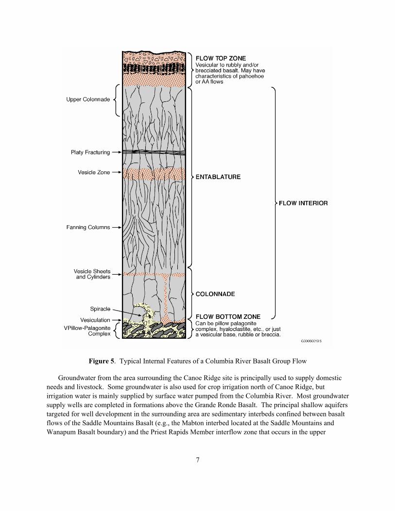
CRBG basalt flows typically consist of a permeable flow top, and dense, relatively impermeable interior (Figure 5). Sedimentary interbeds and basalt contact zones (vesicular flow tops, brecciated flow tops, basal pillow complexes, and basal breccia zones) serve as the primary aquifers in the region, whereas dense flow interiors commonly act as aquitards. The collective contact boundary section between two individual basalt flows (i.e., a flow top and overlying basalt flow bottom) is referred to as an interflow zone. Lateral groundwater flow occurs primarily along the more pervious basalt interflow zones, which are reflective of the conditions and environment of emplacement during the basalt flow extrusion, solidification, and subsequent weathering and soil formation processes. Because of this dependence, a wide variation in groundwater production capacity may be exhibited for individual interflow zones in the CRBG.
The dense interior portions of basalt flows (i.e., entablature and colonnade) comprise approximately 80 to 90% of an individual flow�s thickness, and greatly restrict the movement of groundwater. The ability of dense basalt interiors to act as flow barriers, however, may be compromised by effects of struc-tural deformation. Brittle deformation of the basalt due to faulting and folding can create preferential flow passages through basalt flows and between interflow zones. DOE (1988), Johnson et al. (1993), and Caine et al. (1996) have shown that faults can act both as barriers to lateral groundwater movement and as areas of enhanced vertical groundwater flow. In addition, open primary jointing within basalt flows can also provide localized vertical flow paths through individual basalt flows.
7
Figure 5. Typical Internal Features of a Columbia River Basalt Group Flow
Groundwater from the area surrounding the Canoe Ridge site is principally used to supply domestic needs and livestock. Some groundwater is also used for crop irrigation north of Canoe Ridge, but irrigation water is mainly supplied by surface water pumped from the Columbia River. Most groundwater supply wells are completed in formations above the Grande Ronde Basalt. The principal shallow aquifers targeted for well development in the surrounding area are sedimentary interbeds confined between basalt flows of the Saddle Mountains Basalt (e.g., the Mabton interbed located at the Saddle Mountains and Wanapum Basalt boundary) and the Priest Rapids Member interflow zone that occurs in the upper
8
Wanapum Basalt (Figure 4). The deepest groundwater supply wells are completed in the Frenchman Springs Member, within the lower Wanapum Basalt.
The primary hydrogeologic issues that need to be addressed to determine whether CRBG lavas can function as a natural gas storage facility are grouped into the following topics (Reidel et al. 2002):
• Are there zones within the basalt flows that have sufficient size (lateral extent, thickness, continuity) to store natural gas?
• Do the storage zone(s) have favorable properties (i.e., sufficient porosity and permeability) for efficient natural gas storage and retrievability?
• Is there sufficient structural closure at depth to keep the gas from migrating away from the storage site?
• Are there low-permeability caprocks that will prevent the stored natural gas from leaking from the storage horizon?
• Is the existing groundwater quality favorable (i.e., non-potable and absence of H2S)?
Of the hydrogeologic characterization considerations listed above, structural closure is one of the major natural gas containment issues that must be addressed at this potential storage site. There are over 700 feet of structural closure exhibited at the surface, which decreases to nearly 0 along the peripheral flanks of the dome. In summary, Canoe Ridge appears to be a typical structural dome that has developed along a Yakima Fold anticline.
From field mapping, it is evident that the Elephant Mountain Member thickens away from the crest of the Canoe Ridge, and provides additional closure (at least for the Elephant Mountain Member). That is, thinner lava flows along the crest of the structure suggest that deeper lava flows are structurally higher along the crest than the flows would be if they had a uniform thickness. Unfortunately, the surrounding well data does not provide any information on deeper flows. If Canoe Ridge is like other anticlines where basalts flows are known to thin across the anticlines (Reidel and Hooper 1989), then added closure might be expected from additional flows thinning over Canoe Ridge and thickening off the structure.
3.0 Exploratory Borehole #1
The following discussion presents pertinent information pertaining to the construction history and subsurface geologic conditions encountered within the initial exploratory borehole at Canoe Ridge.
3.1 Borehole History
GTN started exploratory drilling for site characterization on July 2, 1999 using Lang Exploratory Drilling (Salt Lake City, Utah) as the drilling contractor. Drilling continued to a final total depth was
9
reached on July 29, 1999. Lang Exploratory Drilling used a �flooded reverse� drilling technique for drilling of the borehole. Detailed hydrologic testing of selected zones was conducted between July 29 and August 6, 1999, following termination of drilling activities. Total depth of the borehole was in excess of 3,000 feet.
3.2 Borehole Geology
Detailed geologic characterization of an exploratory borehole is imperative to evaluate the potential of basalt horizons for natural gas storage and to determine reservoir structural closure. The stratigraphy is fundamental to addressing the lateral and structural continuity of potential horizons. Identification of stratigraphic intervals was based on basalt chip lithology, x-ray fluorescence (XRF) chemical analysis of selected samples, geophysical log results, and knowledge of basalt stratigraphy of the surrounding area (Reidel et al. 2002). The geologic units penetrated by the Canoe Ridge exploratory borehole are typical of the Columbia River Basalt Group that is exposed in the surrounding region (Figures 3 and 4).
3.2.1 Subsurface Stratigraphy
The youngest basalt flows are part of the Saddle Mountains Basalt (Figure 4). Underlying the Saddle Mountains Basalt is the Wanapum Basalt. The Vantage Horizon, a sedimentary layer, represents a regional hiatus that separates the Grande Ronde Basalt from the overlying Wanapum Basalt. The deepest unit penetrated is the Grande Ronde Basalt, which probably exceeds several kilometers in this area (Reidel and Hooper 1989).
3.2.1.1 Saddle Mountains Basalt
The Saddle Mountains Basalt at Canoe Ridge consists of the Elephant Mountain Member, the Pomona Member, and the Umatilla Member, in descending stratigraphic order (Figure 4). The basalt flows are separated by interbedded sediments of the Ellensburg Formation. The Mabton sediments mark the bottom of the Saddle Mountains Basalt and the top of the Wanapum Basalt.
3.2.1.2 Wanapum Basalt
At the site, the Wanapum Basalt consists of the Priest Rapids Member and the underlying Frenchman Springs Member (Figure 4). The Roza Member, Schumaker Creek Member, and the Eckler Mountain Member are absent in the area of the borehole and the surrounding area. The Priest Rapids Member and Frenchman Springs Member are regionally extensive and cover much of the Columbia Basin. The Roza, Schumaker Creek, and Eckler Mountain Members are more restricted in areal extent and are not expected at Canoe Ridge (Reidel et al. 2002).
3.2.1.3 Grande Ronde Basalt
The Grande Ronde Basalt is the deepest formation of the Columbia River Basalt Group penetrated and, because of its great depth, thickness and continuity of flows (Reidel and Hooper 1989), is an
10
attractive candidate for natural gas storage reservoir exploration. Some individual Grande Ronde flows exceed over 5000 cubic kilometers in volume and cover tens of thousands of square kilometers (Reidel and Hooper 1989; Reidel et al. 2002). Grande Ronde Basalt flows are divided into four units based on magnetostratigraphy/polarity. The formation can also be subdivided into 17 informal members based on lithology and chemical composition (Reidel and Hooper 1989). The second normal polarity (N2 magnetostratigraphic unit) is the youngest of these and was the deepest unit penetrated during drilling.
Individual lava flows are difficult to distinguish from each other in the field, because they are all very similar in appearance. Because of the need to be able to recognize the target horizons in any borehole drilled within the Canoe Ridge site (or for that matter any other site), the flows were examined, sampled and geologically characterized to develop a detailed stratigraphy for the borehole. The Grande Ronde Basalt subdivisions in the borehole are consistent with the regional stratigraphy obtained from other deep boreholes within the Columbia Plateau region. Based on this consistency, a high level of reliability can be assigned to the Grande Ronde Basalt stratigraphic characterization obtained within this borehole. This stratigraphy can be used for detailed stratigraphic identification across the immediate site in future boreholes and recognition of gas storage horizons.
3.2.2 Faulting and Fracture Zones
Fault zones can repeat stratigraphy and, therefore, adversely reduce the amount of closure at depth. Faults are expected in Yakima folds based on detailed mapping of the folded structures in the past within this region (e.g., Reidel 1987). A small fault zone was identified during drilling within the Wanapum Basalt, but the main Columbia Hills fault zone was not encountered in the entire borehole section. A repeat in stratigraphy was confirmed by chemistry of the basalt, however, the repeat was found to be minor compared to the overall amount of closure at the surface. Data from only one borehole does not provide a precise control on the orientation and dip of the fault, nor does it provide sufficient control on closure reduction. Additional boreholes would be required to place constraints on faults encountered in the subsurface.
One other fracture zone was encountered during drilling within the Grande Ronde Basalt. However careful analysis of the stratigraphy using chemistry of basalts as control indicates little vertical movement associated with this feature; and, therefore, appears to have little impact on closure.
4.0 Hydrologic Characterization
Most of the previously identified technical issues to be considered when evaluating the suitability of basalt formations for natural gas storage (Section 2.3) can be evaluated best by conducting a detailed hydrologic site characterization program. This type of characterization involves a series of character-ization test activities that are performed in and between multiple borehole locations.
The principal objectives of a borehole testing program focus on the determination of hydraulic properties and storage properties, and hydrochemical characteristics of groundwater within selected basalt interflow zones. The information derived from individual boreholes and between multiple borehole locations (e.g., multi-well hydraulic tests) is then integrated to address issues concerning the adequacy of
11
natural gas storage within candidate basalt interflow zone horizons. For the Canoe Ridge site, the characterization investigation centered on testing selected basalt interflow zones within the Wanapum and Grande Ronde Basalts. A detailed description of various hydrologic characterization tests and their use in addressing the feasibility of natural gas storage in basalts is presented in Reidel et al. (2002).
4.1 General Testing Strategy
In a comprehensive testing strategy for evaluating the suitability of basalts for natural gas storage, the primary characterization objectives would include: determining hydraulic/storage properties of candidate gas storage reservoir intervals, i.e., basalt interflow zones (flow tops/flow bottoms) and the sealing properties of associated overlying caprock formations, i.e., basalt flow interiors, and paleosol/clay soil zones. Specific hydrogeologic information to be derived from the borehole-testing program for assessing the suitability of basalt flows for natural gas storage includes:
• Interflow Zone Characterization: − Transmissivity, hydraulic conductivity, storativity − Lateral continuity (or presence of lateral barriers) − Degree of vertical hydraulic communication between interflow zones − Operative hydrogeologic aquifer system (e.g., double-porosity1 versus leaky/non-leaky confined)
• Caprock/Aquitard Characterization − Leakage/sealing characteristics, vertical hydraulic diffusivity (vertical hydraulic conductivity/
specific storage) − Lateral continuity and heterogeneity of caprock layers
In addition to the hydraulic property objectives identified above, important information concerning the existing groundwater flow system conditions is obtained through collection of representative groundwater samples for hydrochemical/isotopic characterization; and determination of �undisturbed� hydraulic head conditions for selected higher permeability interflow intervals.
Water sampling and measurement of static hydraulic head are usually not practical for low perme-ability caprock/aquitard intervals. Caprock/aquitard intervals also require longer periods for pressure stabilization prior to initiating hydraulic characterization. Therefore, it is often more economical to characterize low permeability intervals after borehole drilling is completed. Intervals tested as the borehole is progressively advanced can be isolated using commercially available single- or straddle packer test systems. For testing of lower permeability caprock/aquitard formations, however, more sophisticated downhole systems that take into account test system compliance (i.e., imposed pressure transients caused by elastic test equipment response). Any downhole hydrologic test system used for hydrologic characterization should include sensitive pressure transducer systems that will allow hydraulic
1 Double porosity is a rock or formation that has two, distinctively different porosity/permeability structures, e.g., granite or basalt. For fractured rock, the formation responds initially (during hydrologic tests) to the permeability and storage aspects of the fracture system and then later to the matrix conditions.

12
test monitoring on a real-time basis (i.e., no downhole, pressure-bomb recorder-based systems), and use of downhole shut-in tool to minimize borehole storage effects.
Because only one reconnaissance-level borehole was utilized in the initial phase of the site invest-tigation at Canoe Ridge, the level of characterizing the aforementioned interflow and caprock properties required for assessing natural gas feasibility is limited. In addition, due to schedule and cost constraints associated with the initial characterization borehole, no caprock characterization tests were performed. The hydrologic characterization program adopted for the initial exploratory borehole at Canoe Ridge included the determination of hydraulic properties, hydraulic head and general hydrochemical charac-teristics of selected Grande Ronde Basalt interflow zones. In addition, a lower Wanapum Basalt interflow zone was tested to provide comparative results with the underlying Grande Ronde zones tested. The comparison of lower Wanapum Basalt and the underlying Grande Ronde Basalt test results provided information for assessing the distinctive hydrologic break that has been identified regionally for ground-water systems occurring within these two separate CRBG formations (e.g., DOE 1988; Reidel et al. 2002). Grande Ronde Basalt interflow zones selected for detailed testing were identified based on results obtained from dynamic flowmeter testing while pumping the entire open Grande Ronde Basalt borehole section, after reaching the final completion depth of the borehole.
The following discussion provides information obtained from the initial Canoe Ridge characterization borehole and how it relates to known regional background hydrogeologic information.
4.2 Regional Hydrologic Information
An understanding of the regional hydrologic conditions and relationships between principal hydro-geologic units within the CRBG is fundamental for considering natural gas storage and containment in deep basalt aquifers at Canoe Ridge. The summary discussion presented in this chapter is taken primarily from Reidel et al. (2002), which relies largely on material presented in Gephart et al. (1979), Spane (1982), DOE (1988), Drost et al. (1990), and Whiteman et al. (1994).
As discussed in Section 2.0, basalt flows typically consist of a permeable flow top, and a dense, relatively impermeable interior (Figure 5). Sedimentary interbeds and basalt contact zones (vesicular flow tops, brecciated flow tops, basal pillow complexes, and basal breccia zones) serve as the primary aquifers in the region, whereas dense flow interiors commonly act as aquitards. The collective contact boundary section between two individual basalt flows (i.e., a flow top and overlying basalt flow bottom) is referred to as an interflow zone. Lateral groundwater flow occurs primarily along the more pervious basalt interflow zones, which are reflective of the conditions and environment of emplacement during the basalt flow extrusion and solidification, and subsequent weathering and soil formation processes. Because of this dependence, a wide variation in groundwater production capacity may be exhibited for individual interflow zones in the CRBG.
The dense interior portions of basalt flows (i.e., entablature and colonnade) comprise approximately 80% to 90% of an individual flow�s thickness, and greatly restrict the movement of groundwater. The preferential direction of groundwater flow within basalt interiors, however, is vertical. This is attributable to the preferential vertical fracture/joint attitude within flow interiors, and the permeability contrast exhibited between interflow/interior sections.
13
4.2.1 Regional Hydraulic Properties
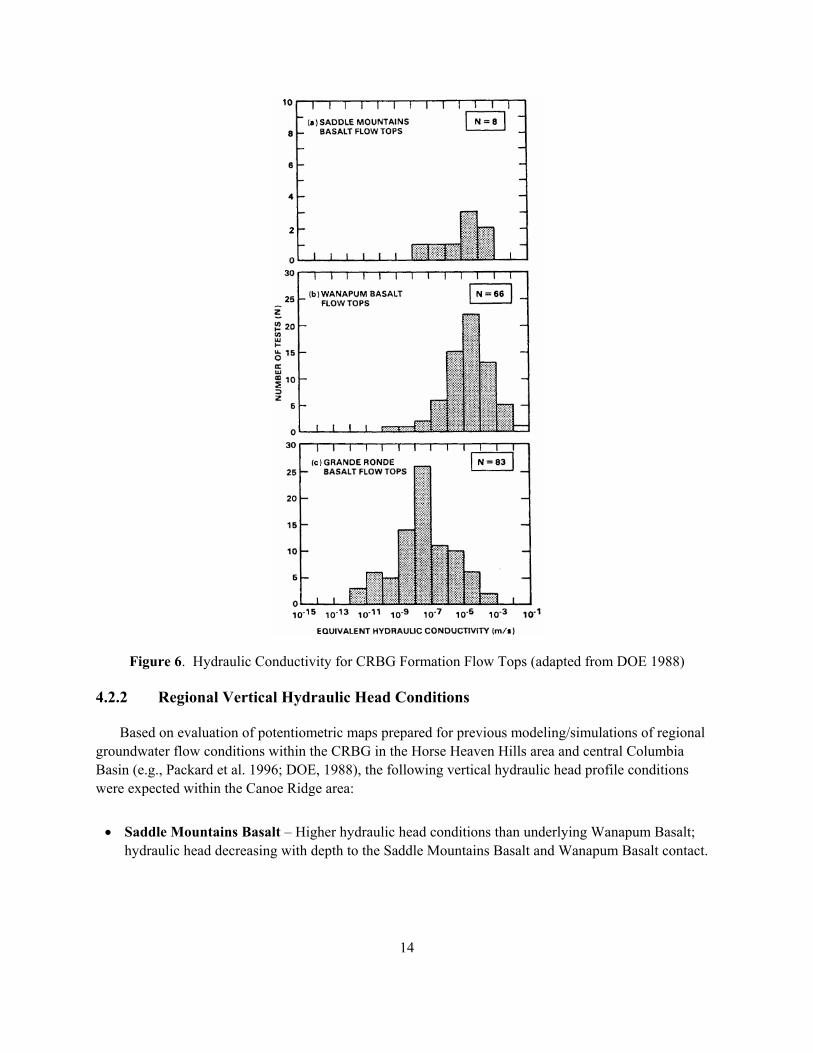
Interflow zones of the CRBG flows typically exhibit a wide range for hydraulic conductivity, ranging over 10 orders of magnitude from 10-2 to 10-12 m/sec (DOE 1988). The collective results of hydraulic tests conducted on the Hanford Site indicate a general pattern of decreasing interflow hydraulic conduc-tivity with depth with Grande Ronde Basalt interflow zones having a geometric mean value two orders of magnitude lower than overlying Saddle Mountains Basalt and Wanapum Basalt counterparts, i.e., 10-7 versus 10-5 m/sec, as shown in Figure 6 (Spane 1982; DOE 1988). Detailed hydraulic testing results of individual basalt interflow zones at individual borehole sites in the Pasco Basin also commonly exhibit a depth dependence, particularly in comparing Grande Ronde Basalt versus Wanapum Basalt interflow zones. As noted in Spane (1982) and DOE (1988), this observed depth-permeability pattern is attributed to compaction (i.e., increasing effective stress) and secondary mineral formation. It should be noted that this is a general observation of depth dependence and exceptions (i.e., deep, high-permeability interflow zones) do occur.
The range and mean for hydraulic conductivity values for Saddle Mountains Basalt and Wanapum Basalt interflow zones within the Pasco Basin compare reasonably well with cited values for these formations in the surrounding region. For example, Hansen et al. (1994) and Whiteman et al. (1994) reported median hydraulic conductivity values of 8.5 x 10⁻⁶ m/sec (2.4 ft/day) and 1.8 x 10⁻⁵ m/sec (5.1 ft/day) for the Saddle Mountains Basalt and Wanapum Basalt, respectively. These values were determined primarily from less precise specific capacity information (i.e., reported drawdown versus pumping rate) that was reported for boreholes within the region, and that included an assumed interflow production zone thickness for all sites of 17 meters. Based on the limitations of the method, it is interesting that there is a reasonable level of correlation (i.e., between Pasco Basin hydrologic test results and regional estimates based on specific capacity relationships) for the Saddle Mountains Basalt and Wanapum Basalt. This is somewhat surprising given the criticism reported in the literature on the use of specific capacity to accurately predict actual hydraulic property conditions (e.g., Razak and Huntley 1991; Huntley et al. 1992; Meier et al. 1999). The reported regional, specific capacity-based median value for Grande Ronde Basalt interflow zones (1.7 x 10⁻⁵ m/sec), however, does not reflect the reduced values reported within Pasco Basin (10-7 m/sec). This discrepancy may be explained by the simple fact that the regional values are primarily for open basalt wells completed at much shallower depths (i.e., <600 meters), whereas Pasco Basin tests are for individual Grande Ronde Basalt interflow zones at depths of between 600 and 1,500 meters. Such a wide difference in reported Grande Ronde Basalt hydraulic conductivity estimates might be expected, if the previously discussed depth dependent mechanism is the cause.
In contrast to interflow zones, basalt flow interiors (caprocks) exhibit considerably lower hydraulic conductivities with values ranging between 10-9 to 10-15 m/sec, and a geometric mean between 10-12 to 10-13 m/sec. A similar decreasing hydraulic conductivity versus depth relationship is also exhibited for flow interior (caprock) tests, suggesting a similar model for its cause. No other test-derived hydraulic conductivity values are reported for flow interiors outside the Pasco Basin.
14
Figure 6. Hydraulic Conductivity for CRBG Formation Flow Tops (adapted from DOE 1988)
4.2.2 Regional Vertical Hydraulic Head Conditions
Based on evaluation of potentiometric maps prepared for previous modeling/simulations of regional groundwater flow conditions within the CRBG in the Horse Heaven Hills area and central Columbia Basin (e.g., Packard et al. 1996; DOE, 1988), the following vertical hydraulic head profile conditions were expected within the Canoe Ridge area:
• Saddle Mountains Basalt � Higher hydraulic head conditions than underlying Wanapum Basalt; hydraulic head decreasing with depth to the Saddle Mountains Basalt and Wanapum Basalt contact.
15
• Wanapum Basalt � Lower hydraulic head conditions than overlying Saddle Mountains Basalt or underlying Grande Ronde Basalt; hydraulic head conditions relatively uniform in the upper Wanapum Basalt and slightly increasing with depth.
• Grande Ronde Basalt � Higher hydraulic head conditions than overlying Wanapum Basalt; hydraulic head conditions increasing with depth.
Similar hydraulic head conditions have been observed in deep boreholes at the U.S. Department of Energy�s (DOE�s) Hanford Site (DOE 1988). In those boreholes, the hydraulic heads are greatest in the Saddle Mountains Basalt and decrease with depth to the underlying Wanapum Basalt. Below the Wanapum Basalt, there is a slight but consistent increase in hydraulic head with depth in the Grande Ronde Basalt.
It is important to note that regionally more abrupt hydraulic head changes may occur near the two major CRBG formational contacts. Where these changes occur, a number of explanations have been proposed. In most cases, the abrupt change in hydraulic head across the formational contacts is attributed to a locally pervasive low-permeability layer. For the Saddle Mountains/Wanapum contact, low perme-ability clay/tuff layers within the intervening Mabton interbed are commonly cited. For the deeper Wanapum/Grande Ronde contact, either: low permeability units within the intervening Vantage interbed; a deeply developed soil on the uppermost Grande Ronde flow (saprolite layer), or a combination of interbed and soil horizon are reported.
The importance of a potential abrupt head change at the major CRBG formational contacts was considered in the designed well sealing/cement applications, for casing strings that encompass these formational contacts. This was to maintain the isolation and integrity of individual aquifers within the CRBG, which is an important regulatory consideration.
4.2.3 Regional Hydrochemistry
Several reports are available that describe the detailed hydrochemical evolution and characteristics of formational groundwaters of the CRBG (e.g., DOE 1988; Steinkampf and Hearn, Jr. 1996). Based on these reports, the expected hydrochemical groundwater conditions for the major CRBG formations within the Canoe Ridge region are summarized below:
• Saddle Mountains Basalt � Relatively low total dissolved solids content (200 to 350 mg/L), primarily a (Ca, Mg)HCO3 chemical/water-type. In areas associated with intensive irrigation, elevated nitrate and higher total dissolved solids concentrations may occur.
• Wanapum Basalt � Relatively low total dissolved solids content (250 to 450 mg/L), primarily a mixed cation - NaHCO3 chemical/water-type.
• Grande Ronde Basalt � Relatively low to moderate total dissolved solids content (350 to >1,000 mg/L), primarily ranging from a NaHCO3 chemical/water-type to a NaCl chemical/water type (for deeper interflow zones). Fluoride concentrations may be elevated (i.e., >2 mg/L and >10 mg/L in some areas, particularly with greater depth within the formation).
16
4.3 Canoe Ridge Characterization Test Results
The objective of the exploratory borehole hydrologic characterization activities focused on deter-mining the hydraulic properties, hydraulic head, and hydrochemical characteristics of groundwater within selected basalt interflow zones of the Wanapum Basalt and Grande Ronde Basalt. The test program included the characterization of one lower Wanapum Basalt interflow zone (for comparison with Grande Ronde results), a composite Grande Ronde test (for selecting individual Grande Ronde zones for detailed characterization), and three Grande Ronde interflow zone tests. It should be noted that because of the proprietary nature of the hydrologic test information, no precise test interval depths or stratigraphic basalt flow identification are provided in the test result discussion. Only relative test zone identification information is provided, with Zone 1 being the deepest, and Zone 3 being the shallowest Grande Ronde basalt interflow zone tested.
4.3.1 Hydraulic Properties
Hydraulic properties were determined from the analysis of monitored well responses associated with air-lift pumping tests. The observed flow-rate variation during the air-lift pumping (drawdown) phase and the pressure recovery following termination of the individual air-lift pumping tests provide two independent analysis means for characterizing the hydraulic properties of the test zones. Downhole pressure readings were recorded at formation depth with a sensitive quartz transducer system for all Grande Ronde Basalt tests (Note: because a downhole pressure transducer system was not available at the time of testing, an electric water-level sensor was used for the initial lower Wanapum Basalt test). Surface flow rates were determined periodically during air-lifting, based on observed surface holding-tank volumetric readings.
The two test characterization methods employed provide a means of demonstrating a level of confidence for the hydraulic property estimates derived for individual test intervals. That is, the two methods should provide similar results if the test assumptions and inherent conceptual model (e.g., non-leaky aquifer) are valid. A brief discussion of the methods is presented below. Because testing was limited to only single-well tests for the exploratory phase, transmissivity was the principal hydrologic parameter determined.
4.3.1.1 Constant-Drawdown (Pressure) Analysis
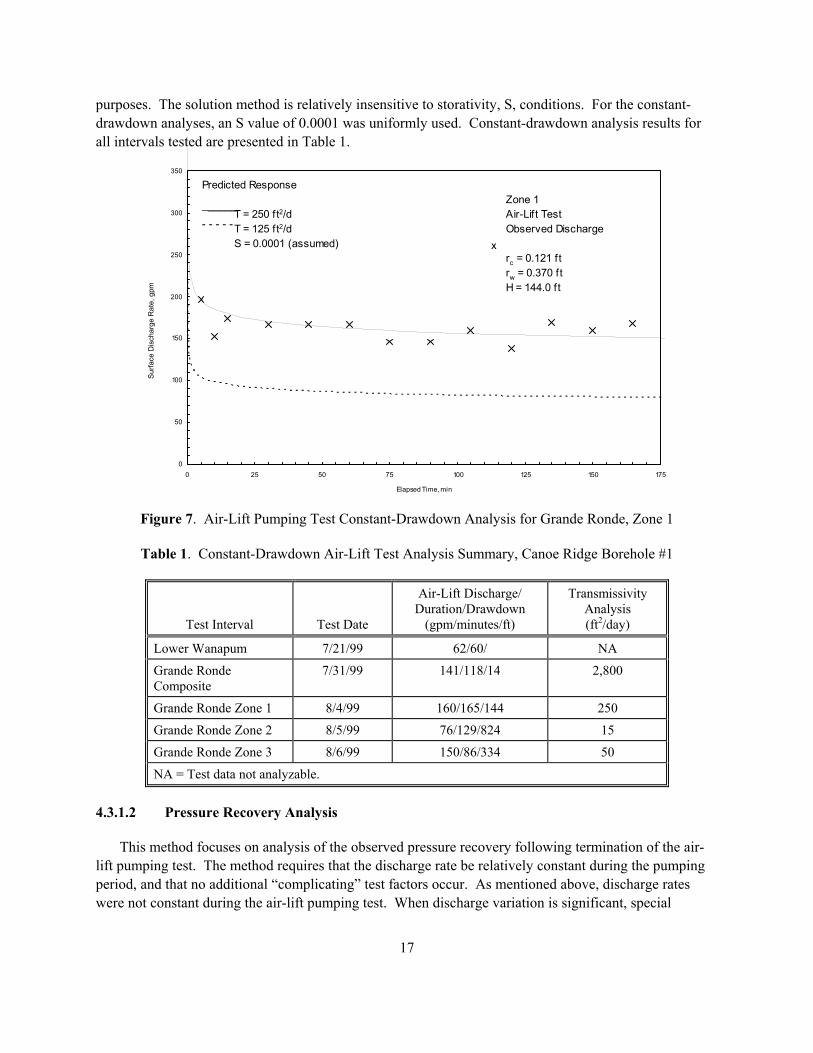
The air-lift testing procedure closely matches conditions of a constant-drawdown (pressure) test. For this test, the water-level within the well was lowered and maintained at a relatively uniform depth. The magnitude of the observed discharge for the given drawdown, and its decline with time provide a means of determining the transmissivity, T, of the interval. The method used for analyzing these tests is based on the solution presented originally by Jacob and Lohman (1952). A constant-drawdown analysis example for one of the Grande Ronde test intervals (Zone 1) is presented in Figure 7. As shown, the predicted response using a T value of 23 m2/day (250 ft2/day) provides a reasonable match to the observed flow rate pattern. As a measure of demonstrating the robustness of the flow-rate match, the best match value (solid line) and one-half the best-match value (dashed line) are shown for comparison
17
purposes. The solution method is relatively insensitive to storativity, S, conditions. For the constant-drawdown analyses, an S value of 0.0001 was uniformly used. Constant-drawdown analysis results for all intervals tested are presented in Table 1.
0
50
100
150
200
250
300
350
0 25 50 75 100 125 150 175
Elapsed Time, min
Predicted Response
T = 250 ft2/d T = 125 ft2/d S = 0.0001 (assumed)
- - - - -
______ Zone 1Air-Lift TestObserved Discharge
rc = 0.121 ftrw = 0.370 ftH = 144.0 ft
x
Figure 7. Air-Lift Pumping Test Constant-Drawdown Analysis for Grande Ronde, Zone 1
Table 1. Constant-Drawdown Air-Lift Test Analysis Summary, Canoe Ridge Borehole #1
Test Interval Test Date
Air-Lift Discharge/ Duration/Drawdown
(gpm/minutes/ft)
Transmissivity Analysis (ft2/day)
Lower Wanapum 7/21/99 62/60/ NA
Grande Ronde Composite
7/31/99 141/118/14 2,800
Grande Ronde Zone 1 8/4/99 160/165/144 250
Grande Ronde Zone 2 8/5/99 76/129/824 15
Grande Ronde Zone 3 8/6/99 150/86/334 50
NA = Test data not analyzable.
4.3.1.2 Pressure Recovery Analysis
This method focuses on analysis of the observed pressure recovery following termination of the air-lift pumping test. The method requires that the discharge rate be relatively constant during the pumping period, and that no additional �complicating� test factors occur. As mentioned above, discharge rates were not constant during the air-lift pumping test. When discharge variation is significant, special
Surfa
ce D
isch
arge
Rat
e, g
pm
18
procedures, e.g., superposition/multi-rate analysis methods (see Earlougher 1977), must be used to obtain reliable analytical results. In addition, a number of �complicating� factors occurred or were imposed by the air-lift process (e.g., pre-test trends, additional well volume imposed by the annular air-line, etc.). Most of these complicating factors were of significance only for test intervals having lower transmis-sivities, and should be accounted for in the recovery analyses.
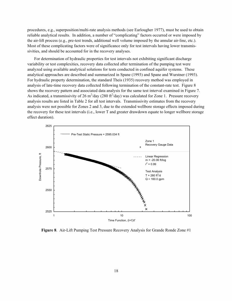
For determination of hydraulic properties for test intervals not exhibiting significant discharge variability or test complexities, recovery data collected after termination of the pumping test were analyzed using available analytical solutions for tests conducted in confined aquifer systems. These analytical approaches are described and summarized in Spane (1993) and Spane and Wurstner (1993). For hydraulic property determination, the standard Theis (1935) recovery method was employed in analysis of late-time recovery data collected following termination of the constant-rate test. Figure 8 shows the recovery pattern and associated data analysis for the same test interval examined in Figure 7. As indicated, a transmissivity of 26 m2/day (280 ft2/day) was calculated for Zone 1. Pressure recovery analysis results are listed in Table 2 for all test intervals. Transmissivity estimates from the recovery analysis were not possible for Zones 2 and 3, due to the extended wellbore storage effects imposed during the recovery for these test intervals (i.e., lower T and greater drawdown equate to longer wellbore storage effect duration).
2525
2550
2575
2600
2625
1 10 100
Time Function, (t+t')/t'
Dow
nhol
e P
ress
ure,
ft
Pre-Test Static Pressure = 2595.034 ft
- - - - -
______
Zone 1Recovery Gauge Data
x
Linear Regressionm = -20.06 ft/logr2 = 0.99
Test AnalysisT = 280 ft2/dQ = 160.0 gpm
Figure 8. Air-Lift Pumping Test Pressure Recovery Analysis for Grande Ronde Zone #1
19
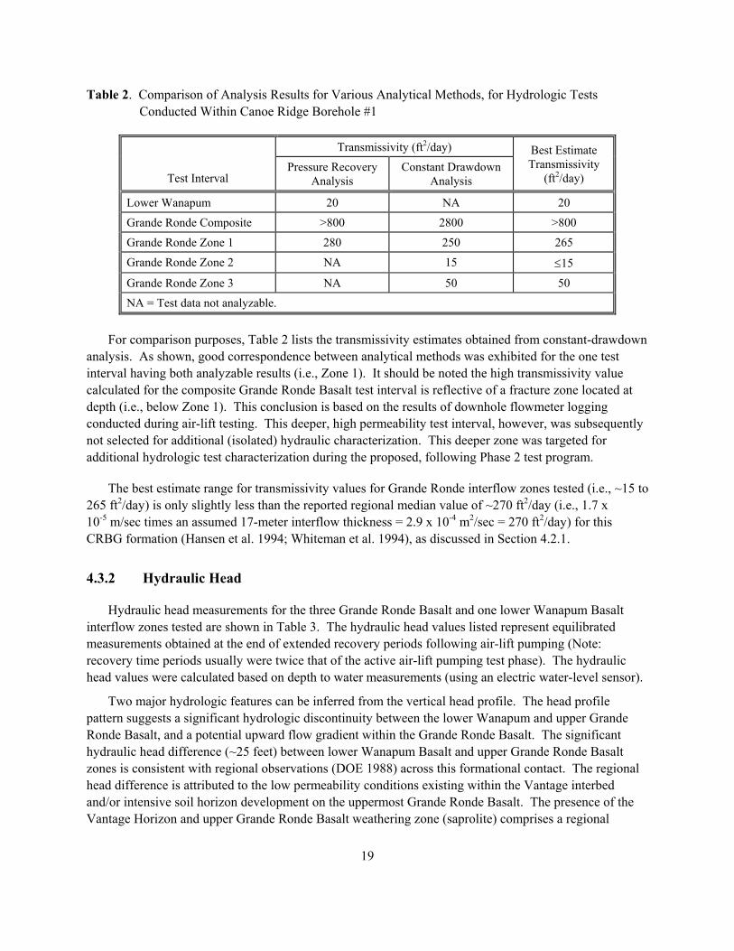
Table 2. Comparison of Analysis Results for Various Analytical Methods, for Hydrologic Tests Conducted Within Canoe Ridge Borehole #1
Transmissivity (ft2/day)
Test Interval Pressure Recovery
Analysis Constant Drawdown
Analysis
Best Estimate Transmissivity
(ft2/day)
Lower Wanapum 20 NA 20
Grande Ronde Composite >800 2800 >800
Grande Ronde Zone 1 280 250 265
Grande Ronde Zone 2 NA 15 ≤15
Grande Ronde Zone 3 NA 50 50
NA = Test data not analyzable.
For comparison purposes, Table 2 lists the transmissivity estimates obtained from constant-drawdown analysis. As shown, good correspondence between analytical methods was exhibited for the one test interval having both analyzable results (i.e., Zone 1). It should be noted the high transmissivity value calculated for the composite Grande Ronde Basalt test interval is reflective of a fracture zone located at depth (i.e., below Zone 1). This conclusion is based on the results of downhole flowmeter logging conducted during air-lift testing. This deeper, high permeability test interval, however, was subsequently not selected for additional (isolated) hydraulic characterization. This deeper zone was targeted for additional hydrologic test characterization during the proposed, following Phase 2 test program.
The best estimate range for transmissivity values for Grande Ronde interflow zones tested (i.e., ~15 to 265 ft2/day) is only slightly less than the reported regional median value of ~270 ft2/day (i.e., 1.7 x 10⁻⁵ m/sec times an assumed 17-meter interflow thickness = 2.9 x 10⁻⁴ m2/sec = 270 ft2/day) for this CRBG formation (Hansen et al. 1994; Whiteman et al. 1994), as discussed in Section 4.2.1.
4.3.2 Hydraulic Head
Hydraulic head measurements for the three Grande Ronde Basalt and one lower Wanapum Basalt interflow zones tested are shown in Table 3. The hydraulic head values listed represent equilibrated measurements obtained at the end of extended recovery periods following air-lift pumping (Note: recovery time periods usually were twice that of the active air-lift pumping test phase). The hydraulic head values were calculated based on depth to water measurements (using an electric water-level sensor).
Two major hydrologic features can be inferred from the vertical head profile. The head profile pattern suggests a significant hydrologic discontinuity between the lower Wanapum and upper Grande Ronde Basalt, and a potential upward flow gradient within the Grande Ronde Basalt. The significant hydraulic head difference (~25 feet) between lower Wanapum Basalt and upper Grande Ronde Basalt zones is consistent with regional observations (DOE 1988) across this formational contact. The regional head difference is attributed to the low permeability conditions existing within the Vantage interbed and/or intensive soil horizon development on the uppermost Grande Ronde Basalt. The presence of the Vantage Horizon and upper Grande Ronde Basalt weathering zone (saprolite) comprises a regional
20
aquitard of low permeability, which tends to separate groundwater flow systems within the two Columbia River Basalt Group formations. This is reflected also by the major hydrochemical differences that exist between Wanapum Basalt and Grande Ronde Basalt groundwaters. These hydrochemical differences are discussed in Section 4.3.3.
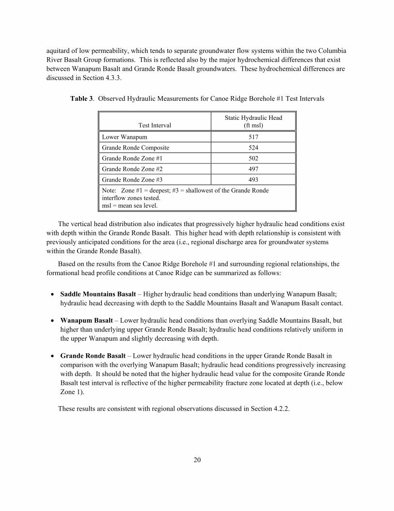
Table 3. Observed Hydraulic Measurements for Canoe Ridge Borehole #1 Test Intervals
Test Interval Static Hydraulic Head
(ft msl)
Lower Wanapum 517
Grande Ronde Composite 524
Grande Ronde Zone #1 502
Grande Ronde Zone #2 497
Grande Ronde Zone #3 493
Note: Zone #1 = deepest; #3 = shallowest of the Grande Ronde interflow zones tested. msl = mean sea level.
The vertical head distribution also indicates that progressively higher hydraulic head conditions exist with depth within the Grande Ronde Basalt. This higher head with depth relationship is consistent with previously anticipated conditions for the area (i.e., regional discharge area for groundwater systems within the Grande Ronde Basalt).
Based on the results from the Canoe Ridge Borehole #1 and surrounding regional relationships, the formational head profile conditions at Canoe Ridge can be summarized as follows:
• Saddle Mountains Basalt � Higher hydraulic head conditions than underlying Wanapum Basalt; hydraulic head decreasing with depth to the Saddle Mountains Basalt and Wanapum Basalt contact.
• Wanapum Basalt � Lower hydraulic head conditions than overlying Saddle Mountains Basalt, but higher than underlying upper Grande Ronde Basalt; hydraulic head conditions relatively uniform in the upper Wanapum and slightly decreasing with depth.
• Grande Ronde Basalt � Lower hydraulic head conditions in the upper Grande Ronde Basalt in comparison with the overlying Wanapum Basalt; hydraulic head conditions progressively increasing with depth. It should be noted that the higher hydraulic head value for the composite Grande Ronde Basalt test interval is reflective of the higher permeability fracture zone located at depth (i.e., below Zone 1).
These results are consistent with regional observations discussed in Section 4.2.2.
21
4.3.3 Hydrochemistry
This section describes the sample and measurement procedures used for hydrochemical character-ization of groundwater samples taken from selected test zones in Canoe Ridge Borehole #1. One sample was collected from the lower Wanapum Basalt before the Grande Ronde Basalt was penetrated to help evaluate groundwater isolation that is reported to occur regionally at this CRBG formational contact. The remaining samples were obtained from selected Grande Ronde Basalt test intervals. Generally, the hydrochemical characteristics determined are consistent with expected conditions, based on regional information available for Wanapum Basalt and Grande Ronde Basalt groundwaters, as discussed in Section 4.2.3. Pertinent sampling information and selected hydrochemical results for the sampled intervals are discussed below.
4.3.3.1 Field Measurement Methods and Conditions
Permit-related parameters were measured with portable field equipment on groundwater samples as they were collected. The HACH Co. DR/2010 spectrophotometer was used for the fluoride measure-ments (SPADNS, method 8029) and for dissolved sulfide (HACH method 8131). Specific conductance was measured with a temperature compensated HACH Co. CO150 conductivity meter (Model 50150) and pH with an Orion meter and probe. Chloride was determined using a HACH Co. digital titrator (Model 16900) with 2.22 M mercuric nitrate as the titrant.
The fluoride method was checked in the field using a secondary standard consisting of a well-water sample with an established fluoride concentration. The field fluoride concentration analysis of this standard sample was within 3% of the expected value (2.9 mg/L). It should also be noted that it was necessary to dilute the Grande Ronde samples by a factor of 10 to be within the operating range of the fluoride method (0 to 2 mg/L).
Conductivity meter was checked with an Oakton test solution (447 µS/cm at 25°C) and found to be within 5% of the expected value. Nearly all the samples were turbid and required filtration prior to analysis. Filtration through a 0.45-micron membrane filter was necessary to remove all the visible particulates for the spectrophotometric analyses. A portable hand operated vacuum/Nalgene filter flask was used for this purpose. Except for the lower Wanapum Basalt sample, all samples analyzed were filtered through a 0.45-micron filter. The Wanapum sample was filtered through a Whatman filter, which did not remove all particulate material.
Purgewater Handling. Purgewater collected during hydrologic testing/sampling that was within regulatory permit limits (e.g., for the lower Wanapum Basalt test interval) was disposed of directly to the ground surface. Purgewater collected during testing/sampling of the Grande Ronde Basalt test intervals, however, exceeded hydrochemical discharge permit limits (Table 4). Subsequently, after consultation with the Washington State Department of Ecology, the decision was made to contain all subsequently produced water from the Grande Ronde Basalt.
Laboratory Measurements. One (1)-liter grab samples were collected during the end of air-lift pumping phases of hydraulic testing and were analyzed at the Pacific Northwest National Laboratory in Richland, Washington for detailed hydrochemical characterization. Analyses were performed on
22
unfiltered (settled) samples that were kept in cold storage until analyzed. Major anions were analyzed by ion chromatography. All other analyses were made by inductively coupled plasma (ICP) emission spectroscopy. Carbonate alkalinity was computed from the elemental carbon ICP results. The latter was used for computing major ion charge balance.
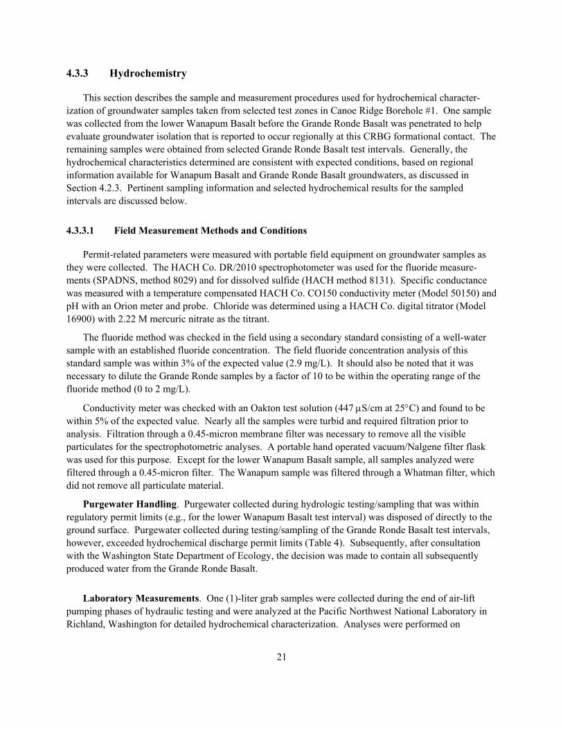
Table 4. Field Hydrochemical Measurement Results
Test Interval Conductivity
µS/cm Fluoride (mg/L)
Chloride (mg/L) pH
Sulfide (mg/L) Comment
Wanapum Basalt
Lower Wanapum Basalt 585 1.3 8.9 10.1 0.2 (turbid)
No odor
Grande Ronde Basalt
Composite Zone(a) (entire Grande Ronde section)
2800 15 730 9.1 0.05 Slight H2S odor
Zone 1 2100 15 650 8.9 -- No odor
Zone 2 2220 11 620 8.7 -- No odor
Zone 3 1700 6.7 500 8.5 0.001 No odor
Note: Zone #1 = deepest; #3 = shallowest of the Grande Ronde interflow zones sampled. (a) Composite Zone results largely reflective of a fracture zone interval located below Zone 1.
Charge balance, or the percent difference in milliequivalents of cations and anions analyzed, was within acceptable ranges (i.e., ≤5%) for all Grande Ronde Basalt test intervals. For the lower Wanapum Basalt test interval, there was an excess of approximately 20% negative charge. This suggests there was an unidentified anionic component. The elevated pH (due to residual effects of recirculated drill cuttings slurry from cementing the permanent casing) most likely accounted for the excess anionic charge not identified with laboratory analyses requested. For example, alkalinity, which was computed from the elemental carbon result, would not account for excess hydroxide present from the cement. Since titration alkalinity (total alkalinity) was not determined, the hydroxide contribution would not be included in the charge balance computation. The lack of a good charge balance in this case, however, should not impact interpretive use of the relative composition of the major anions and cations, as discussed in the following section. Since the same analytical methods yielded good charge balance for the other (i.e., Grande Ronde) test zones, the methods used for the results reported here are judged to be adequate. For the Wanapum sample results, it simply suggests that there is an excess of an unidentified anion (probably OH-). It does illustrate, however, the importance of pumping a larger volume of water from the test zone for those cases where drill-cuttings slurries containing cement are recirculated during the drilling process, as was done during the Wanapum test zone.
In summary, the residual cement-slurry can apparently be carried down into zones at greater depth. The effect of recirculated cuttings slurry must be considered, if optimum conditions for obtaining repre-sentative groundwater samples for hydrochemical characterization is a primary objective. For the initial or exploratory drilling campaign for Canoe Ridge described in this report, water-quality measurements
23
focused primarily on meeting discharge permit purposes, with formation hydrochemistry characterization as a secondary objective. Thus, optimum conditions for obtaining good water samples during the initial drilling campaign did not always exist. It was decided during the planning phase that if favorable formation conditions for subsurface gas storage were found (adequate porosity and structural closure), additional testing would be added if and when new characterization boreholes are drilled.
The following section describes and compares hydrochemical results obtained for the selected CRBG test intervals. As noted previously, because of the proprietary nature of the hydrologic test information, no complete hydrochemical characterization results are provided for precise test interval depths or identified stratigraphic basalt flow horizons. Only selected characteristic hydrochemical parameter information associated with the relative basalt test zones is listed.
4.3.3.2 Wanapum Basalt Results
On July 21, 1999, drilling was temporarily stopped and a short-duration, air-lift pumping test of an interflow zone within the lower Wanapum Basalt was initiated after setting casing. Flow rates for this lower Wanapum Basalt interflow zone during the 60-minute airlift test, steadily declined from an initial 106 to 53 gal/min at test termination. Specific conductance (SC), measured as specific conductance (µS/cm), was checked from discrete samples at 5-minute intervals. SC declined rapidly from an initial ~8,000 µS/cm and appeared to stabilize at about 600 µS/cm after 40 minutes of airlift pumping. The initial high SC values are believed attributable to well casing cementing activities that immediately occurred prior to encountering the lower Wanapum basalt test interval. One-liter grab samples for detailed laboratory analyses and final field determinations were collected at the end of the 60-minute pump test. Selected analytical results are provided in Table 4.
4.3.3.3 Grande Ronde Basalt Results
Three individual Grande Ronde Basalt interflow zones and one composite Grande Ronde Basalt zone were sampled during airlift pumping for hydrologic testing that was conducted between July 31 and August 6, 1999. Groundwater samples were collected near the end of the airlift pumping period for: (1) immediate analysis to assess compliance with regulatory wastewater discharge permit conditions, and (2) for detailed laboratory analysis of major cations and anions. Specific conductance monitored during the course of testing, usually stabilized within 15 to 45 minutes from the start of pumping, depending on flow rate and the interval tested.
The initial specific conductance of the first water sample from the Grande Ronde composite zone (i.e., representing the entire open Grande Ronde Basalt borehole section) was 1,250 µS/cm and stabilized in the range of 2,700 to 2,800 µS/cm after 15 minutes. The specific conductance was 2,720 µS/cm at termination of the airlift pumping (approximately 70 minutes in duration). The surface temperature of the water, based on the HACH conductivity meter, was 38°C to 40°C. There was also a slight odor of hydrogen sulfide.
Replicate 1-liter grab samples for the three discrete depth interval test zones in the Grande Ronde Basalt were collected midway in the pumping period and at the end. The three test zones in the Grande Ronde Basalt produced water that was pale yellow to light brown in color. In contrast, the composite
24
Grande Ronde water was clear with no visible evidence of suspended solids. The apparent discoloration was later shown to be due to iron (total iron concentration declined by nearly a factor of 10 for filtered versus unfiltered samples). The slight cloudiness of the discolored (unfiltered) samples suggested a colloidal iron phase had formed, probably as result of contact with air during airlift pumping. The Grande Ronde composite samples were clear from the initial sampling and never showed any evidence of formation of a precipitate after even several weeks.
A comparison of the selected hydrochemical results presented in Table 4 indicates two significant hydrochemical patterns:
• A distinct hydrochemical difference between groundwaters occurring within the Grande Ronde Basalt and Wanapum Basalt.
• An apparent trend of increasing dissolved solids concentration with depth within the Grande Ronde Basalt.
The distinct difference in hydrochemistry between the major CRBG formations is evident in the chloride and fluoride concentration levels and SC values (Table 4). Grande Ronde Basalt groundwater exhibits chloride concentrations that are a factor of ≥50 greater and fluoride concentrations that are ≥5 greater than exhibited for groundwater occurring within the lower Wanapum Basalt. This distinct hydrochemical separation of groundwaters is consistent with that reported regionally for these two major CRBG formations, and is attributed to the presence of a regional, isolating horizon that is developed on the upper Grande Ronde Basalt (Gephart et al. 1979; DOE 1988; Reidel et al., 2002).
The apparent trend of increasing dissolved solid concentration with depth is supported by the chloride and fluoride values listed in Table 4 (Note: Zone 1 = deepest; Zone 3 = shallowest of the basalt interflow zones sampled). The gradual increase with depth may be attributed to higher temperatures with depth (mineral equilibria controls), and to increased groundwater-rock matrix reaction time (i.e., due to longer groundwater flow paths with depth). Nothing definitive can be derived concerning local interflow isolation and caprock integrity from such gradual hydrochemical patterns. The elevated concentration levels, however, indicate that the Grande Ronde Basalt groundwaters are non-potable and non-suitable for agricultural purposes. This makes Grande Ronde Basalt interflow zones attractive (from a perspective of water quality) for natural gas storage consideration.
5.0 Summary and Conclusions
The geology of the Canoe Ridge test site on the Columbia Hills anticline is typical of similar, moderate-sized structures within the Yakima Fold Belt. The stratigraphy encountered at the surface and in the first exploratory borehole at the site is consistent with geologic conditions exhibited in the surrounding region. The stratigraphic, hydraulic, and hydrochemical information obtained from the initial exploratory borehole at Canoe Ridge all suggest vertical isolation between groundwater occurring within
25
the lower Wanapum Basalt and upper Grande Ronde Basalt. The vertical separation exhibited between groundwater systems within these two major basalt formations, is consistent with what is displayed regionally for CRBG.
Field hydrologic test results indicate the presence of a number of candidate basalt interflow zones in the upper Grande Ronde Basalt that have sufficient permeability and thickness for consideration as candidate horizons for subsurface natural gas storage. However, additional characterization is needed to resolve more complex hydrologic issues concerning the overall suitability of the site that cannot be addressed based on the results obtained from only one exploratory borehole. The distinct differences in hydrochemical composition and hydraulic head data for zones tested in Canoe Ridge Borehole #1 are consistent with a lack of vertical mixing between groundwaters of the upper Grande Ronde Basalt and overlying Wanapum Basalt (i.e., regional caprock provided by the Vantage interbed and saprolite unit developed on the upper Grande Ronde Basalt). Additional testing is needed, however, to confirm the inferred vertical isolation and to assess the lateral extent and continuity of aquifer properties.
Based on the analysis of existing regional and site-specific Canoe Ridge data, it can be generally concluded that subsurface conditions are favorable for the existence of a regional formational caprock(s) and individual flow interior caprocks for the local containment of subsurface natural gas storage. The interpretations of the preliminary structural and stratigraphic data also suggest sufficient closure (lateral containment) at depth within the central portion of the Canoe Ridge area.
6.0 Hydrologic Test Recommendations
The favorable results obtained from the initial exploratory phase of the Canoe Ridge natural gas storage program indicate that additional testing is warranted. It is recommended that additional boreholes be drilled and hydrologically characterized to fully evaluate the potential of Canoe Ridge as a site for natural gas storage. Of highest priority, would be a second borehole to be drilled within proximity to the first for the next phase of detailed, multi-well hydrologic testing. In addition, it is recommended that a seismic survey be conducted across Canoe Ridge to better define the subsurface geologic structure relationships.
The following are recommended hydrologic tests characterizations to further the assessment of the suitability of natural gas storage at Canoe Ridge. The primary focus would be on additional detailed testing of potential storage interflow zones and the overlying caprock characterization using multi-well hydrologic tests. A detailed discussion of these hydrologic characterization methods is presented in Reidel et al. (2002).
1. Fluid flowmeter logging (i.e., production logging) should be performed as a screening tool to identify and to provide initial hydraulic property estimates of permeable interflow zones in all new boreholes. Flowmeter systems used should be of sufficient sensitivity for characterization applications under static and dynamic flow conditions. Ideally, the flowmeter system would include downhole pressure measurement capabilities.
2. Definitive caprock leakage tests will require test durations likely within a 1- to 3-month timeframe, and are best determined analyzing test responses (using a multi-level monitoring system, e.g.,
26
Westbay Instruments, Inc.) over smaller observation well distances, e.g., <300 feet. Composite analysis of more distant test responses (e.g., 1,800 feet) will provide information concerning the lateral uniformity of the leakage values determined.
3. Hydrologic barrier detection for radial distances of 1,500 to 3,000 feet may take test durations of 1 to 4 days to fully resolve.
4. Direct determination of the effective porosity (interconnected pore volume) is best determined using tracer tests. The best tracer test for this objective is a multi-well, forced-gradient tracer test conducted between two boreholes (one injection and one extraction borehole site). Test times required to conduct this type test are highly variable for the various interflow and test site conditions; however, for planning purposes test durations between 2 to 5 days may be required to characterize expected test site conditions (i.e., <300 feet borehole separations).
5. If effective porosity is to be determined indirectly from estimates of interflow storativity, hydrologic tests should be conducted of sufficient length to insure that infinite-acting, radial flow conditions are established at the points of observation. For the test conditions expected at Canoe Ridge, this may require test durations approaching 10 days (i.e., for observation radial distances up to 1,800 feet).
6. As an alternative to long-duration injection tests, pulse-testing (i.e., repeated, short-duration injection and/or extraction tests) offers some interesting possibilities for large-scale hydrologic property characterization, and boundary detection. For best characterization of storativity, injection/extraction periods should be of relatively long duration (e.g., 1,000 minutes). The optimum design of the pulse duration can be determined by evaluating the observed pulse response characteristics at the distant point of observation during the initial pulse period.
7.0 References
BPA. 2000. 2000 Pacific Northwest Loads and Resources Study. Bonneville Power Administration.
Caine, J. S., J. P. Evans, and C. B. Foster. 1996. �Fault Zone Architecture and Permeability Structure.� GEOLOGY 24(11):1025-1028.
DOE (U.S. Department of Energy). 1988. Consultant Draft, Site Characterization Plan, Reference Repository Location, Hanford Site, Washington. DOE/RW-0164, Vols. 1 and 2, U.S. Department of Energy, Washington, D.C.
Drost, B. W., K. J. Whiteman, and J. B. Gonthier. 1990. Geologic Framework of the Columbia Plateau Aquifer System, Washington, Oregon, and Idaho. U.S. Geological Survey, Water-Resources Investigations Report 87-4238, Washington, D.C.
Earlougher, R. C., Jr. 1977. Advances in Well Test Analysis. Soc. of Petroleum Engineers, Monograph Vol. 5, Henry L. Doherty Series.
Gephart, R. E., R. C. Arnet, R. G. Baca, L. S. Leonhart, and F. A. Spane, Jr. 1979. Hydrologic Studies Within the Columbia Plateau, Washington: An Integration of Current Knowledge. RHO-BWI-ST-5, Rockwell Hanford Operations, Richland, Washington.
27
Hansen, A. J., Jr., J. J. Vacaro, and H. H. Bauer. 1994. Ground-Water Flow Simulation of the Columbia Plateau Regional Aquifer System, Washington, Oregon, and Idaho. U.S. Geological Survey, Water-Resources Investigation Report, 91-4187.
Huntley, D., R. Nommensen, and D. Steffey. 1992. �The Use of Specific Capacity to Assess Transmissivity in Fractured-Rock Aquifers.� Ground Water 30(3):396-402.
Jacob and Lohman. 1952. �Nonsteady Flow to a Well of Constant Drawdown in an Extensive Aquifer.� American Geophysical Union, Transaction 33:1192-1207.
Johnson, V. G, D. L. Graham, and S. P. Reidel. 1993. �Methane in Columbia River basalt aquifers: Isotopic and geohydrologic evidence for a deep coal-bed gas source in the Columbia Basin, Washington.� American Association of Petroleum Geologists Bulletin 77(7):1192-1207.
Meier, P. M., J. Carrera, and X. Sanchez-Vila. 1999. �A Numerical Study on the Relationship Between Transmissivity and Specific Capacity in Heterogeneous Aquifers.� Ground Water 37(4):611-617.
Newcomb, R. C. 1971. Geologic Map of the Proposed Paterson Ridge Pumped-storage Reservoir, South-Central Washington. U.S. Geological Survey Miscellaneous Geologic Investigation I-653.
Packard, F. A., A. J. Hansen, and H. H. Bauer. 1996. Hydrology and Simulation of Flow and the Effects of Development Alternatives on the Basalt Aquifers of the Horse Heaven Hills, South-central Washington. U.S. Geological Survey Water-Resources Investigations Report 94-4068.
Razak, M. and D. Huntley. 1991. �Assessing Transmissivity From Specific Capacity in a Large and Heterogeneous Alluvial Aquifer.� Ground Water 29(6):856-861.
Reidel, S. P. 1987. Geologic Map of Saddle Mountains, Central Washington. RHO-BW-SA-463 (5 plates), Westinghouse Hanford Company, Richland, Washington.
Reidel, S. P. and P. R. Hooper (eds.). 1989. Volcanism and Tectonism in the Columbia River Flood Basalt Province. Geological Society of America Special Paper 239, p. 21-53.
Reidel, S. P., V. G. Johnson, and F. A. Spane. 2002. Natural Gas Storage in Basalt Aquifers of the Columbia Basin, Pacific Northwest USA: A Guide to Site Characterization. PNL-13962, Pacific Northwest Laboratory, Richland, Washington.
Schuster, J. E., C. W. Gulick, S. P. Reidel, K. R. Fecht, and S. Zurenko. 1997, Geologic Map of Washington � Southeast Quadrant. Washington Division of Geology and Earth Resources Geologic Map GM-45.
Schuster, J. E. (compiler). 1994. Geologic Maps of the east half of the Washington portion Goldendale 1:100,000 quadrangle and the Washington portion of the Hermiston 1:100,000 quadrangle. Washington Division of Geology and Earth Resources Open-file Ma 94-9, 17 p., 1 plate.
Spane, F. A., Jr. 1982. �Hydrologic Studies Within the Pasco Basin.� In Proceedings of the 1982 National Waste Terminal Storage Program Information Meeting, pp. 23-28. U.S. Department of Energy, DOE/NWTS-30, Richland, Washington.
Spane, F. A., Jr. 1993. Selected Hydraulic Test Analysis Techniques for Constant-Rate Discharge Tests. PNL-8539, Pacific Northwest Laboratory, Richland, Washington.
28
Spane, F. A., Jr. and S. K. Wurstner. 1993. �DERIV: A Program for Calculating Pressure Derivatives for Use in Hydraulic Test Analysis.� Ground Water 31(5):814-822.
Steinkampf, W. C. and P .P. Hearn, Jr. 1996. Ground-Water Geochemistry of the Columbia Plateau Aquifer System, Washington, Oregon, and Idaho. U.S. Geological Survey, Open-File Report 95-467.
Theis. 1935. �The Relationship between the Lowering of the Piezometric Surface and the Rate and Duration of Discharge of a Well using Groundwater Storage.� Transactions, American Geophysical Union 16:519-524.
Whiteman, K. J., J. J. Vaccaro, J. B. Gonthier, and H. H. Bauer. 1994. The Hydrogeologic Framework and Geochemistry of the Columbia Plateau Aquifer System, Washington, Oregon, and Idaho. U.S. Geological Survey, Professional Paper 1413-B.