Technical Bulletin TE-2006-03 Traffic Signal ... accordance with the requirements of CSA Standard...
23
! "#! $ !"#$ %&&’ ( ! %&’($ )**+ )" ! , * $#!"$ +( --,.,’ & &&’& ’’/’.,/,’,# #’.00,’ .. &’ ’,# #’. 00 ,’.. &’ ,"& &/, ,#/ #’&’’, 1)**+1*$ ##,0 #0’&,&2’,3,&’ 4"5’ # /, /,6,. /, " . " #2,- ,’.. ,’,# #&,# #,. ,7& ,- , !"$ ,,0/,’,# #’.00,’.. 8’&-,) /,’’30/, , ,6,. . ,’#,. 2/, #/,.9 /, $$*( ,&2’, "3, &’2,#:3 .30$$*(*$ ; $$*(*) /, $($< ,&2’,"3,&’, ,,/,’’30’=,,,#,/,’,# #’.00,’..9 /!::333/062##:&2’ #:,0>&2’ #:,’,# #’:,’,# #’>.> #>,0:)**( >-,’>..:)**(>-,’>../- !"& ’’"&&’?,. #0’/’’2,.&##&,’’,./, ,#0?,.".&#= ,,/,’’30’=9 /!::333/062##:&2’ #:,0>&2’ #:0,,#/: 2/- &’,/’’’’3 /,#,.&,&’,./,26,3,2,..#&-,,./, ,,,#/,’,# #’. 00 ,’..3/, ’0 .&# ,6’
Transcript of Technical Bulletin TE-2006-03 Traffic Signal ... accordance with the requirements of CSA Standard...

�������������������������������� ��������
������������������������������������������ �������������
�����������������������������
� �������� ����!����� ��������
�
�
�"�� #!� �
$�
�������� ���������������������� �����!"#���� �$
%�����������&��&'
(���!� %&'��($��)**+� ���)"�!��������,��
���������*���� ��� ������
��������$ ����#!"���$� �������+�(���� �--,.���,'��
��&����� ����&��&'�������&�
�''�/'.,�����/,��',#���#�'���.���0���0����,���'��
����.��.�����&�'��',#���#�'���.���0���0����,���'������.��.�����&�'�
�
�
��,��"��&���&��/,�����,#/��#�'��&'',������1)**+1*$�#�#,����0�����#���0��'�&����,��& ��2',� 3,���& '��4 "�5� '�#����/,����������/����,6��,.��/,� "����.� "��#�2��,��-��,���'������.��.�����,',#��#&��,��� ��#��#,����.��,7&��,-,������
!"���$���,,����0����/,��',#���#�'���.���0���0����,���'������.��.���8'&-,�)���/,�''3��0��/� �,�����,��,6��,.���.��, '�#,.�2���/,�����#/,.9���/� �,��$$*(� ����,��& ��2',�"3,���& '����2��,��#:3�.��3��0����$$*(�*$��;�
��$$*(�*)���/� �,��$($<� ����,��& ��2',�"3,���& '�,����,,��/,�''3��0�'��=����,,�,�#,��/,��',#���#�'���.���0���0����,���'������.��.�9��/�� !::333��/�06�2#�#�: &2'�#�����:,�0> &2'�#�����:,',#���#�':,',#���#�'>��.>����#>,�0:)**(
>-��,���'>����.��.�:)**(>-��,���'>����.��.��/�-�
!�"��&������''� "��&�����&��'�?,.����������������#���0��'���/�''�2,� �.&#���#&��,��'��'���,.�����/,�����������,#0��?,.�"�.&#���=����,,��/,�''3��0�'��=9���/�� !::333��/�06�2#�#�: &2'�#�����:,�0> &2'�#�����:0,�,#/:� 2�/�-���& '�,����/�''�''3��/,� �#,.&�,��&�'��,.����/,��26,�3,2���,���.����.#&-,��,.�����/,�� ,����,����,#�������/,��',#���#�'���.���0���0����,���'������.��.��3/,��� '���0��� �.&#�������� �,� �6�'����

�������������������������������� ��������
������������������������������������������ �������������
�����������������������������
� �������� ����!����� ��������
�
�
�"�� #!� �
)�
�-�����!��������,����,�����',#���#�'�����.��.���,#/�'0��������#���',#���#�'����0/3�����,�����.��,-,���#��,��0���,#�������0��,,���0�����#/�"/�,!��4)@*5�(ABCB+AA��-��'!�����#��,�D 06�2#�#��

Engineering Branch 1100 TRAFFIC CONTROLLER CABINETS December 2003
Electrical and Signing Material Standards Page 1
Volume 2
1103 UNINTERRUPTIBLE POWER SUPPLYCABINET
1103.1 SCOPE OF WORK
.1 This specification shall apply to the supply of Uninterruptible Power Supplycabinets including all materials as noted in Materials Standard drawingsMS1103.01 and MS1103.02.
.2 All items listed above and shown on the Material Standards drawings will bereferred to as “product” in this specification.
1103.2 PRODUCT APPROVAL
.1 Only products listed on the Recognized Products List shall be accepted forMinistry of Transportation Projects. The supplier shall reference Chapter102 for the product approval process.
.2 Current approved products can be found at the following link:http://www.th.gov.bc.ca/publications/eng_publications/geotech/Recognized_Products Book.pdf
1103.3 MATERIAL STANDARD DRAWINGS
.1 All products shall be supplied in accordance with the Material Standarddrawings listed in Table 7. Minor variations will be permitted and must beidentified on the shop drawings.
DRAWING NO. DRAWING TITLE
MS1103.01 Cabinet Details and General LayoutMS1103.02 Cabinet Mounting Details
Table 7: Material Standard Drawings for UPS Cabinets
UNINTERRUPTIBLE POWER SUPPLY CABINET
Highway Engineering Branch 1100 TRAFFIC CONTROLLER CABINETS December 2003
Electrical and Signing Material Standards Page 2
Volume 2
.2 The supplier shall verify product hardware and all dimensions and sizes forproper fit prior to fabrication. The supplier shall report any drawing errors tothe Ministry prior to fabrication. Errors or omissions on the drawings shallnot relieve the supplier of its responsibility of delivering a complete workingproduct.
1103.4 MANUFACTURER SHOP DRAWINGS
.1 The supplier shall provide detailed shop drawings of the cabinet for reviewby the Ministry Representative. The supplier shall submit four copies ofdetailed dimensioned layout shop drawings including plans, elevations,sections and details, prior to production.
.2 The Ministry will review the shop drawings to confirm compliance with thegeneral design concept. The review by the Ministry does not relieve thesupplier of their responsibility for errors or omissions in the shop drawingsor of meeting all requirements of this specification.
.3 Fabrication of product shall not commence until the supplier has receivedfinal approved shop drawings and written consent to begin fabrication fromthe Ministry.
1103.5 PRODUCT OPERATING CONDITIONS
.1 The product will be mounted on Ministry Traffic Controller Assemblies(Sections 1201 and 1202).
.2 The product will be exposed to all prevailing climatic conditions throughoutthe province of British Columbia. The cabinet may be exposed totemperatures ranging from -40ºC to +74ºC.
1103.6 GENERAL REQUIREMENTS
.1 The UPS cabinet shall be capable of being mounted on a Ministry Type-S orType-M traffic controller assembly (Sections 1201 and 1202 respectively).
.2 The UPS cabinet shall be capable of being attached to a concrete pad withanchor bolts.
UNINTERRUPTIBLE POWER SUPPLY CABINET
Highway Engineering Branch 1100 TRAFFIC CONTROLLER CABINETS December 2003
Electrical and Signing Material Standards Page 3
Volume 2
.3 The cabinet and door shall be constructed to meet the NEMA 3Rclassification standards.
.4 The panel shall meet CSA Standards and shall bear approval from anorganization accredited by the Standards Council of Canada.
1103.7 PRODUCT MATERIALS AND FINISH
.1 The cabinet shall be constructed using 5052-H32 3.2mm (0.125”) sheetaluminium unless otherwise specified.
.2 All materials shall be new and corrosion resistant for maximum life.
.3 The final product shall be free of dents, scratches, weld burns and abrasionsdetrimental to its strength and general appearance.
.4 All exterior corners shall be rounded to a minimum radius of 6.4mm.
.5 All sharp edges shall be de-burred to a minimum radius of 0.40mm in orderto reduce hazards to service personnel.
.6 The cabinet and all assemblies shall be properly prepared prior topowdercoating. Proper preparation includes:
.1 Cleaning of all surfaces with an alkaline cleaner followed by rinsing.
.2 Brush blasting of all surfaces to 1.5-2.0mil profile.
.7 The cabinet and all painted components shall have a factory appliedpolyester powder coating (see Table 8).
.8 Coatings shall be applied to all cabinet surfaces, including inside walls,doors and ceiling.
.9 All coatings shall be smooth, substantially free of flow lines, paint washout,streaks, orange peel, sagging, runs, blisters and other defects that would inany way impair serviceability or detract from the general appearance.
.10 The finish shall have a minimum pencil lead hardness of HB, using an EagleTurquoise pencil and conform to all test procedures listed in clause1201.13.2.
.11 All exterior connecting hardware (screws, bolts, washers, nuts, etc.) shall bestainless steel. All bolts that are ¼”-20 or larger shall be of the hexagonalhead type.

UNINTERRUPTIBLE POWER SUPPLY CABINET
Highway Engineering Branch 1100 TRAFFIC CONTROLLER CABINETS December 2003
Electrical and Signing Material Standards Page 4
Volume 2
.12 All interior screws shall be of the plated steel pan-head machine type. Nosheet metal or self-tapping screws shall be used.
1103.8 WELDING
.1 All welds shall be in accordance with CAN/CSA W59.
.2 All aluminium welds shall be done by the Gas Metal Arc Welding processor the Gas Tungsten Arc Welding process.
.3 All exterior seams shall be continuously welded and shall be dressed smoothwithout compromising the integrity of the weld.
.4 Welds shall not exhibit cracks, inadequate penetration, lack of fusion, slagor spatter.
.5 Welds shall be free from defects exceeding the limits in size and frequencyof occurrence specified in CAN/CSA W59, Clause 12.
.6 Consumables shall be approved by the Canadian Welding Bureau andconform to the requirements of the American Welding Society (AWS)A5.10 for ER5356 aluminium alloy bare welding electrodes.
.7 All welding electrodes shall conform to CAN/CSA W48. The depositedweld metal shall provide strength, ductility, impact toughness and corrosionresistance equivalent to the base metal.
.8 Procedures and welding operators for welding aluminium shall be qualifiedin accordance with the requirements of CSA Standard WeldingQualifications Code W47.2-1987 as administered by the Canadian WeldingBureau.
1103.9 CABINET DIMENSIONS
.1 The cabinet dimensions shall be as specified in Material Standard drawingMS1103.01.
.2 The cabinet is composed of a main body, roof section and inner wall whichare welded together to fit the door. The cabinet is completely sealed with theexception of the ventilation system.

UNINTERRUPTIBLE POWER SUPPLY CABINET
Highway Engineering Branch 1100 TRAFFIC CONTROLLER CABINETS December 2003
Electrical and Signing Material Standards Page 5
Volume 2
1103.10 CABINET EXTERNAL FEATURES
.1 The cabinet shall have a passive ventilation system as specified in 1103.13.The system may have an air intake and exhaust in the cabinet and/or door.
.2 The door and door locking mechanism shall conform to 1103.12.
.3 The roof of the cabinet shall slope down towards the front of the cabinet.Once the UPS cabinet is installed the slope will drain water away from thetraffic controller cabinet face it is mounted on.
1103.11 CABINET INTERNAL FEATURES
.1 The cabinet shall have three shelves as shown in Material Standard drawingMS1103.01.
.2 The shelves shall be constructed of 3.2 mm aluminium.
.3 The shelves shall be capable of supporting 120kg each.
.4 The shelves shall be supported at a minimum of four points. The shelfsupports shall utilize connecting hardware rather than welding the shelves tothe enclosure.
.5 The bottom shelf shall be designed to be easily removed and installed in theenclosure.
.6 The shelving shall be finished with powder coating as per 1103.7.
.7 The shelves shall be designed to maintain at least a 25mm gap between theirfront face and the cabinet door when it is closed. All wiring between theUPS on the upper shelf and the batteries on the lower shelves will passthrough the gap.
1103.12 CABINET DOOR CONSTRUCTION
1103.12.1 Door Features
.1 The cabinet door shall be constructed in accordance with Material Standarddrawing MS1103.01.

UNINTERRUPTIBLE POWER SUPPLY CABINET
Highway Engineering Branch 1100 TRAFFIC CONTROLLER CABINETS December 2003
Electrical and Signing Material Standards Page 6
Volume 2
.2 The cabinet door shall be constructed in such a way as to prevent anynoticeable twisting and flexing in any position. Reinforcement may be usedif required.
.3 The door shall utilize a three point draw roller latching mechanism andhandle. The rollers shall be a commercially available roller with ballbearings. The centre catch and pushrods shall be zinc plated. A Teflon padshall be installed on the inside of the door opening to ensure gasketcompression and to reduce wear. The pad shall be located in the path of thecentre locking latch.
.4 The latching handle shall be of zinc-plated steel construction with a187.5mm handle and an 82mm steel shank. The handle assembly shall notbe painted.
.5 The handle shank shall not protrude more than 10mm past the lock assemblyinto the cabinet.
.6 The handle shall have provision for padlocking in the closed position.
.7 All mounting hardware joining the door to the cabinet shall be plated steelmachine screws. All door mounting hardware shall be installed to facilitateremoval and re-attachment by service personnel.
.8 Hinges shall be installed to facilitate removal and re-attachment by servicepersonnel. The hinge mounting shall not be accessible from the outsidewhen the door is closed. Refer to Table 8 for approved hinge materials.
.9 The door hinges shall be attached to the cabinet so that the door opens to theright as per Material Standard drawing MS1103.01.
.10 The door shall be provided with a door stop assembly capable of holding thedoor open at 90 degrees. Caution must be exercised to ensure that the area issufficiently reinforced.
.11 The door may include an air intake as part of the ventilation systemspecified in 1103.13.
.12 The door shall be provided with closed cell, neoprene gasket material asspecified in 1103.12.2.
.13 The door shall be electrically bonded to the cabinet. The bonding conductorshall be connected to the door using a crimp-on connector affixed directly tobare metal (remove coating material).

UNINTERRUPTIBLE POWER SUPPLY CABINET
Highway Engineering Branch 1100 TRAFFIC CONTROLLER CABINETS December 2003
Electrical and Signing Material Standards Page 7
Volume 2
1103.12.2 Door Gasket
.1 Closed cell neoprene gasket material shall be installed around the insideperimeter of the door. Refer to Table 8 for approved gasket materials.
.2 Gaskets shall be applied in such a manner as to maintain a dust and watertight seal and to allow for proper door operation.
.3 The gasket shall be installed in one continuous piece per side (i.e. fourpieces total) and shall be permanently bonded to the metal. The top andbottom pieces of the gasket shall be applied such that the seams with theside pieces are horizontal. This will prevent any water that enters the top ofthe door from dripping down through a vertical gasket seam.
.4 The gasket shall be appropriately sized to eliminate gaps at all jointsincluding any potential shrinkage. The outside surface of the gasket shall becovered with a silicon lubricant to prevent the gasket sticking to the matingsurface of the cabinet.
1103.13 VENTILATION
1103.13.1 General
.1 The cabinet shall be provided with a passive convection ventilation systemwith an air intake vent at the bottom of the cabinet and an air exhaust vent atthe top. The intake may be part of the cabinet or the door while the exhaustshall be in the uppermost part of the cabinet only.
.2 The vents shall be constructed to prevent rain, snow or slush driven by windor passing vehicles into the cabinet interior. Vent holes shall be no largerthan 3.2mm in diameter to reduce the entry of foreign particles.
.3 The bottom of the vent assemblies shall be formed into a waterproof sumpwith drain holes to the outside. The drain holes shall be de-burred such thatwater exiting the vents shall flow unimpeded.
.4 The exhaust hole openings shall exit near the cabinet ceiling.
.5 The purpose of the vent holes is to ensure adequate air flow through thecabinet. Vents shall be designed such that service personnel can easily clearthe holes of obstructions.

UNINTERRUPTIBLE POWER SUPPLY CABINET
Highway Engineering Branch 1100 TRAFFIC CONTROLLER CABINETS December 2003
Electrical and Signing Material Standards Page 8
Volume 2
1103.14 CABINET MOUNTING
.1 The UPS cabinet shall be supplied with all hardware necessary to mount andconnect it to a Ministry of Transportation M or S type traffic controllercabinet as described in 1103.14.2 and Materials Standard drawingMS1103.02. All acceptable cabinet mounting equipment is listed in Table 8.
.2 When installed external to an existing Ministry Traffic Controller Assembly,the following requirements shall apply:
.1 The UPS cabinet shall be seated on angle aluminium attached to theside (S-type) or rear (M-type) of the traffic controller cabinet.
.2 The aluminium seat shall be attached to the traffic controller cabinetwith four 1/4" flat head bolts, nuts and washers. The seat shall becapable of supporting the full load of the cabinet and the potential loadof each shelf as specified in 1103.11.3.
.3 When seated the UPS cabinet will be attached to the traffic controllercabinet with six 5/16" bolts, nuts, washers and sealing washers asshown in MS1103.02.
.4 All electrical wiring between the two cabinets will pass through a 1”short nipple, installed with a locknut and a sealing washer as shown inMS1103.02.
.5 All mounting hardware shall be installed so as not to conflict with anyequipment internal to the traffic controller cabinet during installation.

UNINTERRUPTIBLE POWER SUPPLY CABINET
Highway Engineering Branch 1100 TRAFFIC CONTROLLER CABINETS December 2003
Electrical and Signing Material Standards Page 9
Volume 2
1103.15 APPROVED PRODUCTS FOR UPS CABINETCONSTRUCTION
.1 The approved mounting, environmental and miscellaneous hardware, as wellas finishing products for UPS cabinet construction are listed in Table 8.
LABEL (ID) FUNCTION APPROVED PRODUCT
DoorHardware
Door Hinges SOUTHCO In-line Hinges Screw size 10-32Part # 96-10-500-50 (appropriate screw lengths)
Door Handle Padlockable “L” Handle FAUCHER #671-5051
Or EBERHARD #8055
Door Mechanism FAUCHER Zinc Plated 3-point ball bearing drawroller latching mechanism with the centre case#700-5463 , roller bearings and zinc platedpushrods (see MS1213.03)
EBERHARD # 5647-2XX & EBERHARD #5559 latching point
MiscellaneousHardware
Filler / Sealant “DAP” brand (Alex Plus) latex sealant. (Grey)THERMOBOND 3 Dura Chem Inc
Gasket Material SPAE-NAUR #892-485 or FAUCHER 623-2110neoprene
Oxide Inhibitor PENETROX A BURNDY Cat # P8A
LABEL (ID) FUNCTION APPROVED PRODUCT TABLE 2 CONT’D
Cabinet Finish Powder Coating PROTECH Powder # PS221A40
LABEL (ID) FUNCTION APPROVED PRODUCT
CabinetMountingHardware
Cabinet seatingbracket
1/4” x 1.75” x 1.75” aluminum angle 30” long
Bracket mountinghardware
Four 1/4”-20 x 1” flat head machine screws
Four 1/4” plated flat washers
Four 1/4”-20 plated nyloc nuts
Inter-cabinetelectrical raceway
1” Short Nipple with locknut and sealing washer

UNINTERRUPTIBLE POWER SUPPLY CABINET
Highway Engineering Branch 1100 TRAFFIC CONTROLLER CABINETS December 2003
Electrical and Signing Material Standards Page 10
Volume 2
and gasket 2.5” OD x 1.5” ID x 1/4" neoprene gasket withPSA backing
Cabinet-to-cabinetmounting hardware
Six 5/16”-18 x 1 1/2" hex head capscrews
Twelve 5/16” plated flat washers
Twelve 1.5” OD x 3/8” ID x 1/8” fender washers
Six 1.5” OD x 1/2" ID x 1/4" neoprene gaskets withPSA backing
Six 5/16”-18 plated nyloc nutsTable 8: Approved Materials for UPS Cabinet Construction


Engineering Branch 1300 GENERAL EQUIPMENT FOR December 2003
Electrical and Signing Material Standards TRAFFIC CONTROLLER ASSEMBLIES Page 1
Volume 2
1314 UNINTERRUPTIBLE POWER SUPPLIES
1314.1 SCOPE OF WORK
.1 This specification shall apply to the supply of Uninterruptible Power Supply(UPS) equipment. UPS equipment shall refer to the following:
.1 Uninterruptible Power Supply units.
.2 UPS bypass and transfer equipment.
.3 UPS batteries.
.4 UPS system cabinets.
.2 All items listed above and shown on the Material Standard drawings will bereferred to as “product” in this specification.
.3 All electrical equipment that the UPS provides battery backup power to shallbe referred to as the “load” in this specification.
.4 The 120VAC line input to the UPS and its load shall be referred to as “utilitypower” in this specification.
.5 “Qualified” utility power refers to electrical power considered acceptable fordirect application to the load. The parameters of qualified utility power andtheir accepted tolerances are detailed in 1314.5.4.
1314.2 PRODUCT APPROVAL
.1 Only products listed on the Recognized Products List shall be accepted forMinistry of Transportation Projects. The supplier shall reference Chapter102 for the product approval process.
.2 Current approved products can be found at the following link:http://www.th.gov.bc.ca/publications/eng_publications/geotech/Recognized_Products_Book.pdf
UNINTERRUPTIBLE POWER SUPPLIES
Highway Engineering Branch 1300 GENERAL EQUIPMENT FOR December 2003
Electrical and Signing Material Standards TRAFFIC CONTROLLER ASSEMBLIES Page 2
Volume 2
1314.3 PRODUCT OPERATING CONDITIONS
.1 All UPS equipment, batteries and enclosures will be installed throughoutBritish Columbia and are subject to a wide range of climates. All equipmentshall operate in an ambient temperature range of -37 oC to +74oC.
.2 The UPS equipment, batteries and enclosures will be installed on theroadside where they are constantly exposed to dust, dirt and vehicleemissions.
1314.4 PRODUCT GENERAL REQUIREMENTS
.1 All product shall be fully enclosed and suitable for use in enclosed outdoorenvironments.
.2 All product must be CSA or ULC approved.
1314.5 UNINTERRUPTIBLE POWER SUPPLY UNITS
1314.5.1 General Requirements
.1 The UPS unit must accept 120VAC utility power at its input and provide120VAC at its output.
.2 The UPS unit shall be capable of continuous in-line operation with the load.
.3 The UPS unit must have internal dry-contact Form C ‘alarm relays’ forexternal equipment control during UPS events.
.4 The UPS may have an output to control an external transfer switch whichallows the UPS to operate in a standby configuration.
1314.5.2 UPS Unit Dimensions
.1 The UPS unit dimensions shall not exceed 381 x 508 x 191mm. The UPSwill sit in a cabinet such that the visible dimensions shall be 381mm verticaland 508mm horizontal when viewed from the front.
.2 The UPS control panel shall be located such that it is accessible from thefront of the unit when in installed in a cabinet.

UNINTERRUPTIBLE POWER SUPPLIES
Highway Engineering Branch 1300 GENERAL EQUIPMENT FOR December 2003
Electrical and Signing Material Standards TRAFFIC CONTROLLER ASSEMBLIES Page 3
Volume 2
1314.5.3 UPS General Operating Specifications
.1 When qualified utility power is present at the UPS Line Input the UPS shalloperate in its ’Online’ mode. In the Online mode the load is powered by theAC utility power and the UPS charges its backup batteries.
.2 When unqualified utility power is present at the UPS Line Input the UPSshall operate in its ‘Backup’ mode. In Backup mode the battery bank shallpower the load via the UPS inverter.
.3 The total transfer time between the loss of qualified utility power at the UPSLine Input and the switching of the UPS to Backup mode shall not exceed150ms.
.4 If utility power is restored while the UPS is in Backup mode, the UPS shalldelay for a minimum of 15 seconds of continuous qualified utility powerbefore switching to Online mode.
.5 When the UPS batteries are fully discharged due to a prolonged Backupperiod the UPS shall turn itself off. When qualified utility power is restoredthe UPS shall automatically restart, power its load, and begin recharging thebatteries.
.6 The UPS shall have a thermostat regulated internal fan to cool the inverter inBackup mode.
.7 The UPS shall utilize a temperature-compensated battery charger. The UPSshall have an external temperature probe to measure the battery temperature.The external probe shall be removable and be supplied with a minimum 1mcable. For safety reasons, the battery charger shall stop charging the batteriesif ambient temperature exceeds 50 oC.
.8 A summary of the UPS general operating specifications is shown in Table23.
PARAMETER SPECIFICATION
UPS Online to Backup Mode Transfer Time < 150ms
UPS Backup to Online Mode Transfer Time > 15s of continuous qualified utilitypower
Table 23: UPS General Operating Specifications
UNINTERRUPTIBLE POWER SUPPLIES
Highway Engineering Branch 1300 GENERAL EQUIPMENT FOR December 2003
Electrical and Signing Material Standards TRAFFIC CONTROLLER ASSEMBLIES Page 4
Volume 2
1314.5.4 UPS Electrical Input Specifications
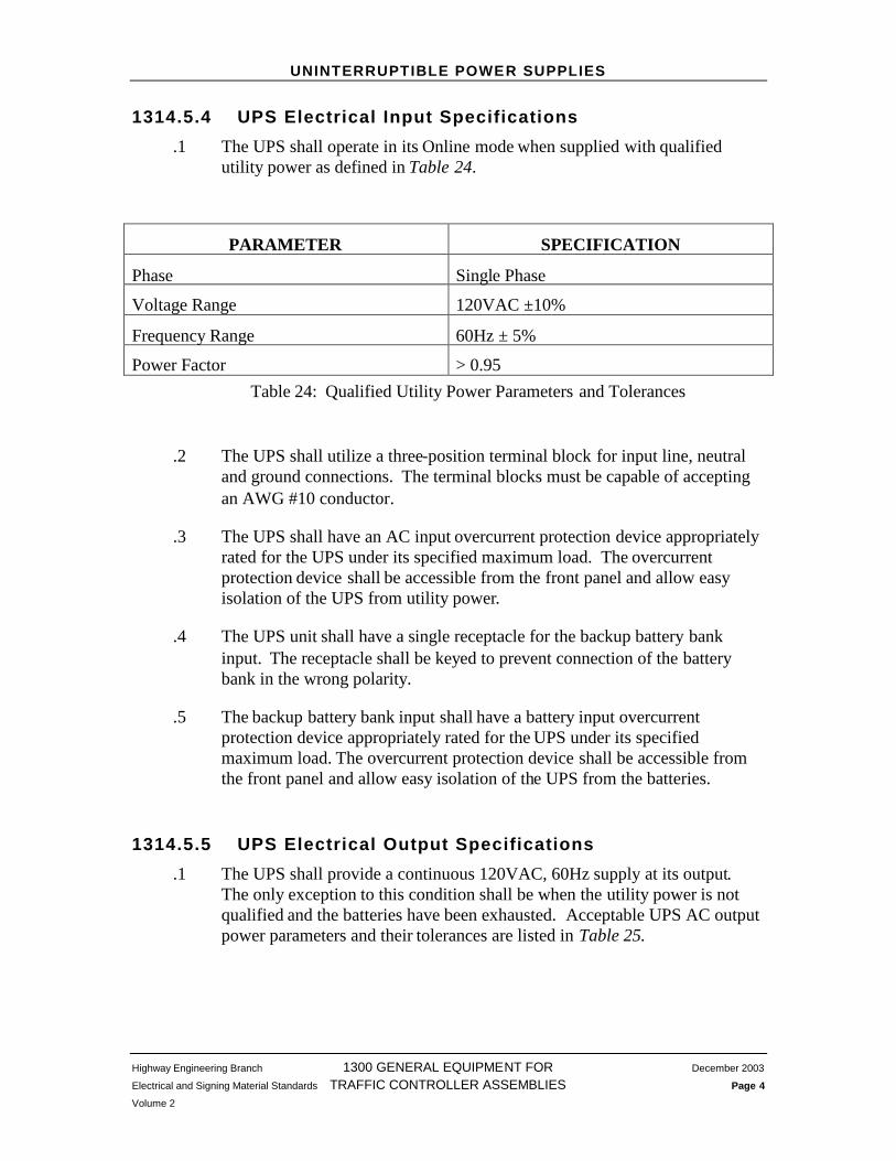
.1 The UPS shall operate in its Online mode when supplied with qualifiedutility power as defined in Table 24.
PARAMETER SPECIFICATION
Phase Single Phase
Voltage Range 120VAC ±10%
Frequency Range 60Hz ± 5%
Power Factor > 0.95Table 24: Qualified Utility Power Parameters and Tolerances
.2 The UPS shall utilize a three-position terminal block for input line, neutraland ground connections. The terminal blocks must be capable of acceptingan AWG #10 conductor.
.3 The UPS shall have an AC input overcurrent protection device appropriatelyrated for the UPS under its specified maximum load. The overcurrentprotection device shall be accessible from the front panel and allow easyisolation of the UPS from utility power.
.4 The UPS unit shall have a single receptacle for the backup battery bankinput. The receptacle shall be keyed to prevent connection of the batterybank in the wrong polarity.
.5 The backup battery bank input shall have a battery input overcurrentprotection device appropriately rated for the UPS under its specifiedmaximum load. The overcurrent protection device shall be accessible fromthe front panel and allow easy isolation of the UPS from the batteries.
1314.5.5 UPS Electrical Output Specifications
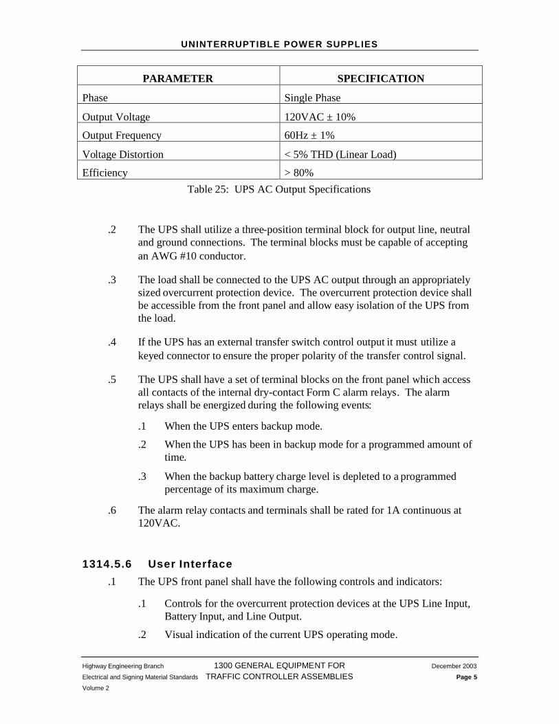
.1 The UPS shall provide a continuous 120VAC, 60Hz supply at its output.The only exception to this condition shall be when the utility power is notqualified and the batteries have been exhausted. Acceptable UPS AC outputpower parameters and their tolerances are listed in Table 25.
UNINTERRUPTIBLE POWER SUPPLIES
Highway Engineering Branch 1300 GENERAL EQUIPMENT FOR December 2003
Electrical and Signing Material Standards TRAFFIC CONTROLLER ASSEMBLIES Page 5
Volume 2
PARAMETER SPECIFICATION
Phase Single Phase
Output Voltage 120VAC ± 10%
Output Frequency 60Hz ± 1%
Voltage Distortion < 5% THD (Linear Load)
Efficiency > 80%Table 25: UPS AC Output Specifications
.2 The UPS shall utilize a three-position terminal block for output line, neutraland ground connections. The terminal blocks must be capable of acceptingan AWG #10 conductor.
.3 The load shall be connected to the UPS AC output through an appropriatelysized overcurrent protection device. The overcurrent protection device shallbe accessible from the front panel and allow easy isolation of the UPS fromthe load.
.4 If the UPS has an external transfer switch control output it must utilize akeyed connector to ensure the proper polarity of the transfer control signal.
.5 The UPS shall have a set of terminal blocks on the front panel which accessall contacts of the internal dry-contact Form C alarm relays. The alarmrelays shall be energized during the following events:
.1 When the UPS enters backup mode.
.2 When the UPS has been in backup mode for a programmed amount oftime.
.3 When the backup battery charge level is depleted to a programmedpercentage of its maximum charge.
.6 The alarm relay contacts and terminals shall be rated for 1A continuous at120VAC.
1314.5.6 User Interface
.1 The UPS front panel shall have the following controls and indicators:
.1 Controls for the overcurrent protection devices at the UPS Line Input,Battery Input, and Line Output.
.2 Visual indication of the current UPS operating mode.

UNINTERRUPTIBLE POWER SUPPLIES
Highway Engineering Branch 1300 GENERAL EQUIPMENT FOR December 2003
Electrical and Signing Material Standards TRAFFIC CONTROLLER ASSEMBLIES Page 6
Volume 2
.3 Visual indication of the current UPS output load.
.4 Visual indication of the current backup battery charge level.
.5 A fault indicator.
.2 The UPS shall utilize a computer-industry standard interface to facilitatedirect communication between the UPS and a computer. Examples ofstandard interfaces include RS-232 serial ports, USB ports and RJ-45network ports.
.3 Each UPS unit shall be capable of communicating with a PC runningMicrosoft Windows 2000 or Windows XP. The user shall be able to changethe following UPS operating parameters through the communications link:
.1 Monitor and reset a count of how many times the UPS has enteredbackup mode.
.2 Program the amount of time that the delay-on relay will energize afterthe UPS has entered backup mode.
.3 Program the backup battery charge level at which the low-battery relaywill energize.
1314.5.7 Product Warranty
.1 The manufacturer shall warranty the UPS equipment for any material andlabour manufacturing defects for a period of 2 years after the date of supply.
1314.6 UPS BYPASS AND TRANSFER EQUIPMENT
.1 The UPS system may use an external bypass switch for the isolation of theUPS from utility power during maintenance.
.2 The UPS system may use an external automatic transfer switch, placing theUPS in a ‘standby’ configuration. When utility power is qualified thetransfer switch:
.1 Connects utility power to the load.
.2 Connects utility power to the UPS for battery charging and monitoring.
.3 Isolates the UPS output from the load.
When utility power becomes unqualified the transfer switch:
.1 Disconnects the utility power from the load.
UNINTERRUPTIBLE POWER SUPPLIES
Highway Engineering Branch 1300 GENERAL EQUIPMENT FOR December 2003
Electrical and Signing Material Standards TRAFFIC CONTROLLER ASSEMBLIES Page 7
Volume 2
.2 Connects the UPS output to the load.
.3 A bypass switch may be combined with a transfer switch to form a singledevice.
1314.6.3 Bypass Switch Requirements
.1 The external bypass switch shall provide separate Line, Neutral and Groundterminal blocks for connection to utility power and the load. The terminalblocks must be capable of accepting an AWG #10 conductor.
.2 The bypass switch shall provide connection to the UPS AC inputs andoutputs. The connection may be through terminal blocks or terminatedcabling.
.3 In its non-bypass state the switch shall connect utility power to the UPSinput, and the UPS output to the load.
.4 In its bypass state the switch shall connect utility power direct to the load andisolate all UPS connections from utility power. The bypass state is intendedto allow maintenance personnel to service the UPS unit safely.
.5 The bypass switch shall be a “make-before-break” type or similar switch thatensures power to the load is not interrupted during switching.
.6 The bypass switch shall at a minimum be rated for currents equal to therating of the UPS AC Input overcurrent protection device.
.7 The bypass switch shall be capable of being mounted to the interior wall ofan enclosure.
1314.6.4 Transfer Switch Requirements
.1 The transfer switch shall provide separate Line, Neutral and Ground terminalblocks for connection to utility power and the load. The terminal blocksmust be capable of accepting an AWG #10 conductor.
.2 The transfer switch shall provide connection to the UPS AC inputs andoutputs. The connection may be through terminal blocks or terminatedcabling.
.3 The transfer switch state may be controlled internally or through aconnection to the UPS unit.
UNINTERRUPTIBLE POWER SUPPLIES
Highway Engineering Branch 1300 GENERAL EQUIPMENT FOR December 2003
Electrical and Signing Material Standards TRAFFIC CONTROLLER ASSEMBLIES Page 8
Volume 2
.4 The default state of the transfer switch shall keep utility power connected tothe load. Therefore if there is a malfunction with the UPS or the transferswitch control wiring the utility power will be connected to the load.
.5 A UPS system utilizing an external transfer switch shall meet the UPStransfer time specifications in Table 23. Therefore the transfer switch mustswitch the UPS output to the load within 150ms of detecting unqualifiedutility power.
1314.7 UPS BATTERIES
1314.7.1 General Battery Requirements
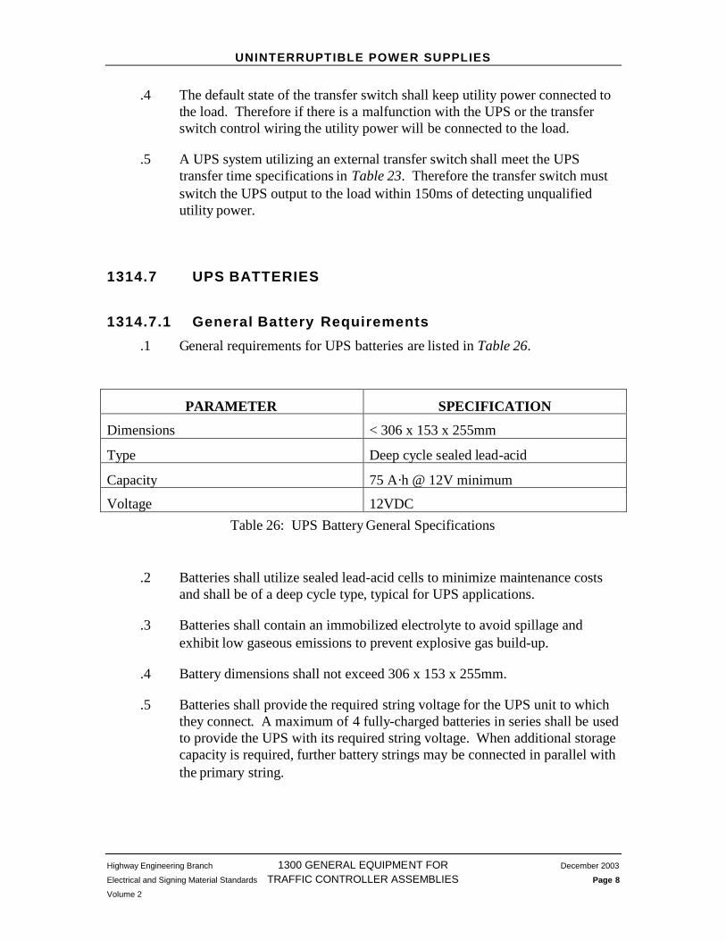
.1 General requirements for UPS batteries are listed in Table 26.
PARAMETER SPECIFICATION
Dimensions < 306 x 153 x 255mm
Type Deep cycle sealed lead-acid
Capacity 75 A·h @ 12V minimum
Voltage 12VDCTable 26: UPS Battery General Specifications
.2 Batteries shall utilize sealed lead-acid cells to minimize maintenance costsand shall be of a deep cycle type, typical for UPS applications.
.3 Batteries shall contain an immobilized electrolyte to avoid spillage andexhibit low gaseous emissions to prevent explosive gas build-up.
.4 Battery dimensions shall not exceed 306 x 153 x 255mm.
.5 Batteries shall provide the required string voltage for the UPS unit to whichthey connect. A maximum of 4 fully-charged batteries in series shall be usedto provide the UPS with its required string voltage. When additional storagecapacity is required, further battery strings may be connected in parallel withthe primary string.

UNINTERRUPTIBLE POWER SUPPLIES
Highway Engineering Branch 1300 GENERAL EQUIPMENT FOR December 2003
Electrical and Signing Material Standards TRAFFIC CONTROLLER ASSEMBLIES Page 9
Volume 2
.6 Batteries shall be supplied with all necessary wiring and connectors to createthe battery string and connect it to the UPS. The wiring and connectors shallbe colour coded for ease of installation. Battery post connectors shall besupplied with insulated colour-coded covers for safety.
.7 The battery connection to the UPS shall have the following characteristics:
.1 A single receptacle on the UPS shall be utilized for connection of allexternal batteries.
.2 The receptacle shall be keyed to prevent the accidental connection ofthe batteries in the wrong polarity.
.3 The corresponding battery connector shall be designed such that thereis no risk of short circuit or danger to service personnel whendisconnecting the batteries from the UPS.
1314.7.2 Battery Warranty
.1 The manufacturer shall replace at their own cost any batteries which do notoperate at a minimum of 80% of their stated capacity during their first 5years of normal usage. Normal usage is defined as continuous use within thespecified operating conditions as advertised by the manufacturer at the timeof purchase.
1314.8 UNINTERRUPTIBLE POWER SUPPLY CABINET
.1 Refer to Chapter 1103 Uninterruptible Power Supply Cabinet for all details.