RC3000E Configuration Guide 201001davantel.com/user/image/rc3000e-configuration-guide...RC3000E...
45
www.raisecom.com RC3000E Configuration Guide
Transcript of RC3000E Configuration Guide 201001davantel.com/user/image/rc3000e-configuration-guide...RC3000E...
www.raisecom.com
RC3000E Configuration Guide
Legal Notices
Raisecom Technology Co., Ltd makes no warranty of any kind with regard to this manual, including, but not limited to, the implied warranties of merchantability and fitness for a particular purpose. Raisecom Technology Co., Ltd shall not be held liable for errors contained herein or direct, indirect, special, incidental or consequential damages in connection with the furnishing, performance, or use of this material.
Warranty.
A copy of the specific warranty terms applicable to your Raisecom product and replacement parts can be obtained from Service Office.
Restricted Rights Legend.
All rights are reserved. No part of this document may be photocopied, reproduced, or translated to another language without the prior written consent of Raisecom Technology Co., Ltd. The information contained in this document is subject to change without notice.
Copyright Notices.
Copyright ©2010 Raisecom. All rights reserved. No part of this publication may be excerpted, reproduced, translated or utilized in any form or by any means, electronic or mechanical, including photocopying and microfilm, without permission in Writing from Raisecom Technology Co., Ltd.
Trademark Notices
is the trademark of Raisecom Technology Co., Ltd.
Java™ is a U.S. trademark of Sun Microsystems, Inc.
Microsoft® is a U.S. registered trademark of Microsoft Corporation.
Windows NT® is a U.S. registered trademark of Microsoft Corporation.
Windows® 2000 is a U.S. registered trademark of Microsoft Corporation.
Windows® XP is a U.S. registered trademark of Microsoft Corporation.
Windows® and MS Windows® are U.S. registered trademarks of
Microsoft Corporation.
Contact Information
Technical Assistance Center
The Raisecom TAC is available to all customers who need technical assistance with a Raisecom product, technology, or, solution. You can communicate with us through the following methods:
Address: Building 2, No. 28 of the Shangdi 6th Street, Haidian District, Beijing 100085
Tel: +86-10-82883305
Fax: +86-10-82883056
World Wide Web
You can access the most current Raisecom product information on the World Wide Web at the following URL:
http://www.raisecom.com
Feedback
Comments and questions about how the RC3000E system software works are welcomed. Please review the FAQ in the related manual, and if your question is not covered, send email by using the following web page:
http://www.raisecom.com/en/xcontactus/contactus.htm.
If you have comments on the RC3000E specification, instead of the web page above, please send comments to:
We hope to hear from you!

CONTENTS Chapter 1 System Overview -------------------------------------------------------------------------- 1
1.1 Procedure of device startup --------------------------------------------------------------------------------------1 Chapter 2 How to Use The Commands Line ---------------------------------------------------- 3
2.1 Software and hardware environment --------------------------------------------------------------------------3 2.2 Getting helps -----------------------------------------------------------------------------------------------------------3 2.3 How to use history command ------------------------------------------------------------------------------------3 2.4 How to use edit properties ----------------------------------------------------------------------------------------3 2.5 Commands line modes ---------------------------------------------------------------------------------------------4
Chapter 3 System Configuration-------------------------------------------------------------------- 5 3.1 Basic system commands and configuration----------------------------------------------------------------5
3.1.1 Basic operation -------------------------------------------------------------------------------------------------------------------------- 5 3.1.2 Showing and configuring of basic system information------------------------------------------------------------------------- 5
3.2 Management of configuring file and startup file -----------------------------------------------------------7 3.2.1 Configure startup file ------------------------------------------------------------------------------------------------------------------- 7 3.2.2 Host file ------------------------------------------------------------------------------------------------------------------------------------ 7 3.2.3 Update host software from bootrom------------------------------------------------------------------------------------------------ 7 3.2.4 Update host software in Privileged EXEC mode ------------------------------------------------------------------------------ 10 3.2.5 Update software of service card from network management card --------------------------------------------------------11
3.3 User management --------------------------------------------------------------------------------------------------12 Chapter 4 Clock Source Configuration ----------------------------------------------------------13
4.1 Overview ---------------------------------------------------------------------------------------------------------------13 4.2 Configure application ---------------------------------------------------------------------------------------------13
Chapter 5 Network Protocol Configuration-----------------------------------------------------17 5.1 Mappings from IP address to physical address----------------------------------------------------------17 5.2 Configure IP address of SNMP interface -------------------------------------------------------------------17 5.3 Configure SNMP COMMUNITY table -------------------------------------------------------------------------18 5.4 Configure SNMP trap-server host-----------------------------------------------------------------------------19
Chapter 6 Cross Connection Configuration----------------------------------------------------20 6.1 Overview ---------------------------------------------------------------------------------------------------------------20 6.2 Slot cross configuration -----------------------------------------------------------------------------------------20
Chapter 7 Uplink Card Protection Switch Configuration ----------------------------------22 7.1 Overview ---------------------------------------------------------------------------------------------------------------22 7.2 Configure application ---------------------------------------------------------------------------------------------22
Chapter 8 Typical Application of Network Management Configuration---------------26 8.1 Overview ---------------------------------------------------------------------------------------------------------------26 8.2 Local management configuration application ------------------------------------------------------------26 8.3 Point-to-Point remote network management application---------------------------------------------27 8.4 Remote device cascade network management application------------------------------------------30 8.5 SA data transparent transmission management application ----------------------------------------32
Appendix A Acronyms ------------------------------------------------------------------------------------35
Preface
About This Manual
This manual introduces primary functions of the configuration management software for RC series products. This manual is applicable for configuring software of RC3000E.
Who Should Read This Manual
This manual is a valuable reference for sales and marketing staff, after service staff and telecommunication network designers. For those who want to have an overview of the features, applications, structure and specifications of RC3000E devices, this is also a recommended document.
Relevant Manuals
RC3000E Commands Notebook
Organization
Chapter 1 System Overview
Introducing function features of RC3000E device systematically.
Chapter 2 How to Use the Command Line
This chapter introduces the using features and basic methods of configuring RC3000E device by command line.
Chapter 3 System Configuration
This chapter introduces the basic function and configuration of system commands of RC3000E device.
Chapter 4 Clock Source Configuration
This chapter introduces the configuration of RC3000E clock source.
Chapter 5 Network Protocol Configuration
This chapter introduces the network protocol function and its configuration methods.
Chapter 6 Cross Connect Configuration
Introduces cross connection configuration in RC3000E.
Chapter 7 Uplink Card Protection Switch Configuration
Introduces uplink card protection switch configuration in RC3000E.
Chapter 8 Typical Application of Network Management Configuration
This chapter introduces typical application of RC3000E network management configuration.

Compliance
The RC series products developed by Raisecom are strictly complied with the following standards as well as ITU-T, IEEE, IETF and related standards from other international telecommunication standard organizations:
YD/T900-1997 SDH Equipment Technical Requirements - Clock
YD/T973-1998 SDH 155Mb/s and 622Mb/s Technical conditions of optical transmitter module and receiver module
YD/T1017-1999 Network node interface for the Synchronous Digital Hierarchy (SDH)
YD/T1022-1999 Requirement of synchronous digital hierarchy (SDH) equipment function
YD/T1078-2000 SDH Transmission Network Technique Requirements-Interworking of Network Protection Architectures
YD/T1111.1-2001 Technical Requirements of SDH Optical Transmitter/Optical Receiver Modules——2.488320 Gb/s Optical Receiver Modules
YD/T1111.2- 2001 Technical Requirements of SHD Optical Transmitter/Optical Receiver Modules——2.488320 Gb/s Optical Transmitter Modules
YD/T1179- 2002 Technical Specification of Ethernet over SDH
G.703 Physical/electrical characteristics of hierarchical digital interfaces
G.704 Synchronous frame structures used at 1544, 6312, 2048, 8448 and 44 736 kbit/s hierarchical levels
G.707 Network node interface for the synchronous digital hierarchy (SDH)
G.774 Synchronous digital hierarchy (SDH) - Management information model for the network element view
G.781 Synchronization layer functions
G.783 Characteristics of synchronous digital hierarchy (SDH) equipment functional blocks
G.784 Synchronous digital hierarchy (SDH) management
G.803 Architecture of transport networks based on the synchronous digital hierarchy (SDH)
G.813 Timing characteristics of SDH equipment slave clocks (SEC)
G.823 The control of jitter and wander within digital networks which are based on the 2048 kbit/s hierarchy
G.825 The control of jitter and wander within digital networks which are based on the synchronous digital hierarchy (SDH)
G.826 End-to-end error performance parameters and objectives for international, constant bit-rate digital paths and connections
G.828 Error performance parameters and objectives for international, constant bit-rate synchronous digital paths
G.829 Error performance events for SDH multiplex and regenerator sections
G.831 Management capabilities of transport networks based on the synchronous digital hierarchy

(SDH)
G.841 Types and characteristics of SDH network protection architectures
G.842 Interworking of SDH network protection architectures
G.957 Optical interfaces for equipments and systems relating to the synchronous digital hierarchy
G.691 Optical interfaces for single channel STM-64 and other SDH systems with optical amplifiers
G.664 Optical safety procedures and requirements for optical transport systems
I.731 ATM Types and general characteristics of ATM equipment
I.732 ATM Functional characteristics of ATM equipment
IEEE 802.1Q Virtual Local Area Networks (LANs)
IEEE 802.1p Traffic Class Expediting and Dynamic Multicast Filtering
IEEE 802.3 CSMA/CD Access Method and Physical Layer Instruction
www.raisecom.com User Manual
1
Chapter 1 System Overview
RC3000 is a multi-service multiplexing device that in support of cross connecting 16 lines of E1 at random. TDM signal of different service cards realizes DXC matrix switchover via main board. Meanwhile, RC3000E is in support of access multi-service to transmission line, including Ethernet data, V5 card, V24 data, asynchronous serial communication data, voice FXO, voice FXS, voice E&M, etc.
Decentralization management is been adopted by RC3000E. The main cards including network management function, cross-connect function and clock function, etc. shorted as DXC card. Slot 4 is for uplink card, providing E1 protection switch. According to the different single card type, the DXC card and other service card exchange switch information with remote modules via backboard. The DXC card provides CONSOLE, TELNET, SNMP network management interfaces which provide unified network management and comprehensive deployment to nodes, remote and ring network devices.
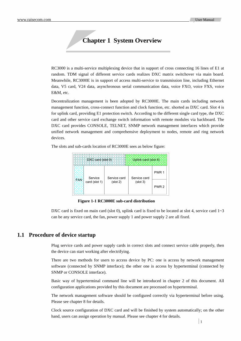
The slots and sub-cards location of RC3000E sees as below figure:
DXC card (slot 0) Uplink card (slot 4)
Service card (slot 1)
Service card (slot 2)
Service card (slot 3)
PWR 1
PWR 2
FAN
Figure 1-1 RC3000E sub-card distribution
DXC card is fixed on main card (slot 0), uplink card is fixed to be located at slot 4, service card 1~3 can be any service card, the fan, power supply 1 and power supply 2 are all fixed.
1.1 Procedure of device startup
Plug service cards and power supply cards in correct slots and connect service cable properly, then the device can start working after electrifying.
There are two methods for users to access device by PC: one is access by network management software (connected by SNMP interface); the other one is access by hyperterminal (connected by SNMP or CONSOLE interface).
Basic way of hyperterminal command line will be introduced in chapter 2 of this document. All configuration applications provided by this document are processed on hyperterminal.
The network management software should be configured correctly via hyperterminal before using. Please see chapter 8 for details.
Clock source configuration of DXC card and will be finished by system automatically; on the other hand, users can assign operation by manual. Please see chapter 4 for details.

www.raisecom.com User Manual
2
The chapter 8 brings users forth to manage remote device. To finish e1 protection switch by RC3000E uplink card please refer to chapter 7.
Note: Configuration of service card can be stored in cross card. So when plugging single card into a slot of the same type service card, the DXC card will restore its configuration by automation.
www.raisecom.com User Manual
3
Chapter 2 How to Use The Commands Line
2.1 Software and hardware environment
Hardware environment: RC3000E device platform
PC serial interface
Software environment: WIN98/WIN2000/WINDOWS XP
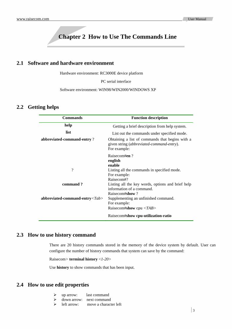
2.2 Getting helps
Commands Function description
help Getting a brief description from help system. list List out the commands under specified mode.
abbreviated-command-entry ? Obtaining a list of commands that begins with a given string (abbreviated-command-entry). For example:
Raisecom#en ? english enable
? Listing all the commands in specified mode. For example: Raisecom#?
command ? Listing all the key words, options and brief help information of a command. Raisecom#show ?
abbreviated-command-entry<Tab> Supplementing an unfinished command. For example: Raisecom#show cpu <TAB>
Raisecom#show cpu-utilization-ratio
2.3 How to use history command
There are 20 history commands stored in the memory of the device system by default. User can configure the number of history commands that system can save by the command:
Raisecom> terminal history <1-20>
Use history to show commands that has been input.
2.4 How to use edit properties
up arrow: last command down arrow: next command left arrow: move a character left

www.raisecom.com User Manual
4
right arrow: move a character right <Backspace>: delete a character in front of the cursor <Ctrl>+y: show historical commands <Ctrl>+l: clear the screen <Ctrl>+u: show the using condition of the memory <Ctrl>+z: return to the privileged EXEC mode from any other modes
2.5 Commands line modes
Mode Mode description Access Identifier
User EXEC Users are authorized to configurebasic information and display parameters, etc. of terminal.
Log onto the device and input user name and
password.
Raisecom>
Privileged EXEC
Users are authorized to configurebasic information, such as system time, and display
parameters. Unauthorized to configure running information.
Using command enable under user EXEC mode.
Raisecom#
Global configuration
Users are authorized to configureall running parameters.
Using command config under Privileged EXEC
mode.
Raisecom (config)#
Slot configuration
Users are authorized to configureall running parameters of service
card in slot.
Using command slot under global configuration mode.
Raisecom (config-slot/PATH)# PATH: slot path
Remote configuration
Users are authorized to configure all running
parameters of remote devices.
Using command remote under global configuration
mode.
Raisecom (config-remote/PATH)#PATH: remote device path
Interface configuration
Users are authorized to configureparameters of local Ethernet
network management interface, SDH interface, local and remote E1 interface, and PDH interface.
Using command interface under global configuration mode, slot configuration
mode or remote configuration mode.
Raisecom (config-TYPE/PATH)# TYPE: interface type like pdh, stm,e1, etc. PATH: interface path
Note: Device Path Definition:
Slot path: “/n”, where n indicates slot number; Remote device path: “/n/a/b…”, where n indicates slot number, a indicates first layer remote
device number; b indicates second layer remote device number. RC3000E is able to bear four layers of remote devices at most.
Interface path: local interface path is denoted as “slot path/ interface number”; remote interface path is denoted as “remote device path/ interface number”.

www.raisecom.com User Manual
5
Chapter 3 System Configuration
3.1 Basic system commands and configuration
3.1.1 Basic operation chinese show command help information in Chinese
english show command help information in English
clear clear showing information on the screen
list show all command list under specified mode
quit quit from logon
exit return to previous mode
end return to privileged mode, same as <Ctrl+z>
3.1.2 Showing and configuring of basic system information Common operations under user EXEC mode:
terminal line set terminal line, no format can restore default value; terminal time-out set terminal time-out maximal value; terminal history set recorded history commands.
Common operations under privileged EXEC mode: reboot reboot device; logout logout from current logging, the command quit and exit can also logout; hostname change system name, no format command can restore default name; show cpu-utilization-ratio show utilization ratio of CPU; show general alarm show general alarm information.
Basic information configuration under global configuration mode:
show device-info show information of device shelf; device assetid set device asset ID; device description set description information of device; device shelf assetid set asset ID of device shelf.
Common operations under global configuration mode and privileged EXEC mode: device lock lock out device, not allowed to enter global configuration mode (only global configuration mode); device unlock unlock device, allowed to enter global configuration mode (only global configuration mode); show clock show system time; clock set change system time; show slot show list of local cards; show device show list of remote device.
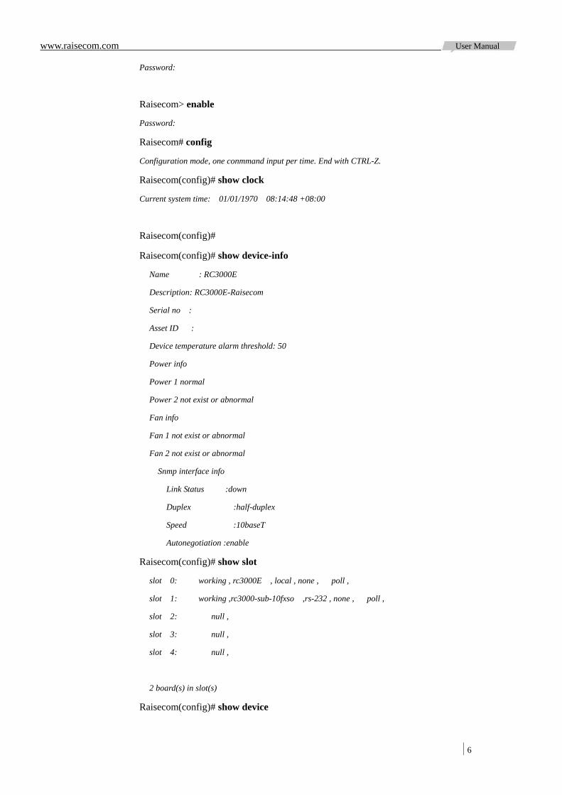
Example: Logon system (use username raisecom), show time and basic information of device, logout:
Login: raisecom
www.raisecom.com User Manual
6
Password:
Raisecom> enable
Password:
Raisecom# config
Configuration mode, one conmmand input per time. End with CTRL-Z.
Raisecom(config)# show clock
Current system time: 01/01/1970 08:14:48 +08:00
Raisecom(config)#
Raisecom(config)# show device-info
Name : RC3000E
Description: RC3000E-Raisecom
Serial no :
Asset ID :
Device temperature alarm threshold: 50
Power info
Power 1 normal
Power 2 not exist or abnormal
Fan info
Fan 1 not exist or abnormal
Fan 2 not exist or abnormal
Snmp interface info
Link Status :down
Duplex :half-duplex
Speed :10baseT
Autonegotiation :enable
Raisecom(config)# show slot
slot 0: working , rc3000E , local , none , poll ,
slot 1: working ,rc3000-sub-10fxso ,rs-232 , none , poll ,
slot 2: null ,
slot 3: null ,
slot 4: null ,
2 board(s) in slot(s)
Raisecom(config)# show device
www.raisecom.com User Manual
7
0 device(s) found
Raisecom(config)#
Raisecom(config)# exit
Raisecom# logout
Login:
Note: The logon password won’t show in the screen.
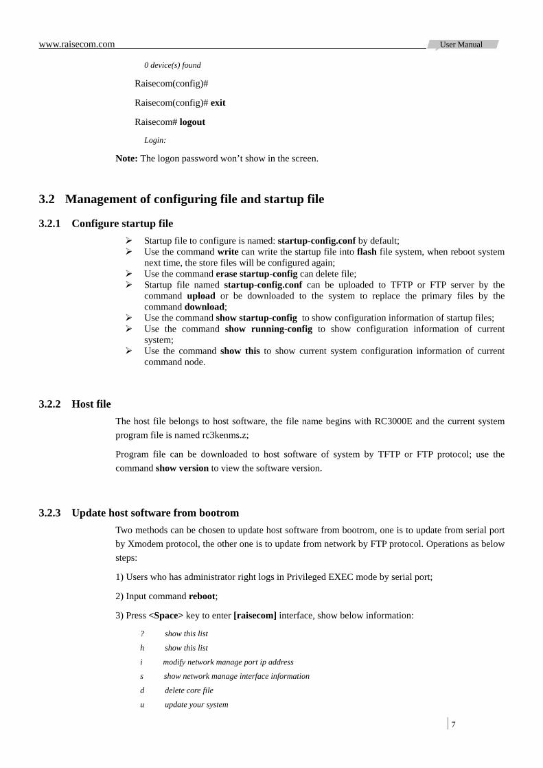
3.2 Management of configuring file and startup file
3.2.1 Configure startup file Startup file to configure is named: startup-config.conf by default; Use the command write can write the startup file into flash file system, when reboot system
next time, the store files will be configured again; Use the command erase startup-config can delete file; Startup file named startup-config.conf can be uploaded to TFTP or FTP server by the
command upload or be downloaded to the system to replace the primary files by the command download;
Use the command show startup-config to show configuration information of startup files; Use the command show running-config to show configuration information of current
system; Use the command show this to show current system configuration information of current
command node.
3.2.2 Host file The host file belongs to host software, the file name begins with RC3000E and the current system program file is named rc3kenms.z;
Program file can be downloaded to host software of system by TFTP or FTP protocol; use the command show version to view the software version.
3.2.3 Update host software from bootrom Two methods can be chosen to update host software from bootrom, one is to update from serial port by Xmodem protocol, the other one is to update from network by FTP protocol. Operations as below steps:
1) Users who has administrator right logs in Privileged EXEC mode by serial port;
2) Input command reboot;
3) Press <Space> key to enter [raisecom] interface, show below information:
? show this list
h show this list
i modify network manage port ip address
s show network manage interface information
d delete core file
u update your system
www.raisecom.com User Manual
8
m update microcode
r reboot system
test test the hardware
4) Input u to update system, the interface shows as below:
choose mode for updating core file.
-----------------------------------
- 1. | serial -
-----------------------------------
- 2. | network -
-----------------------------------
please input choose the mode...
5) Input 1 to choose serial interface for downloading:
choose serial baud rate for updating core file.
-----------------------------------
- 1. | 9600 -
-----------------------------------
- 2. | 14400 -
-----------------------------------
- 3. | 19200 -
-----------------------------------
- 4. | 38400 -
-----------------------------------
please input choose the baud rate...
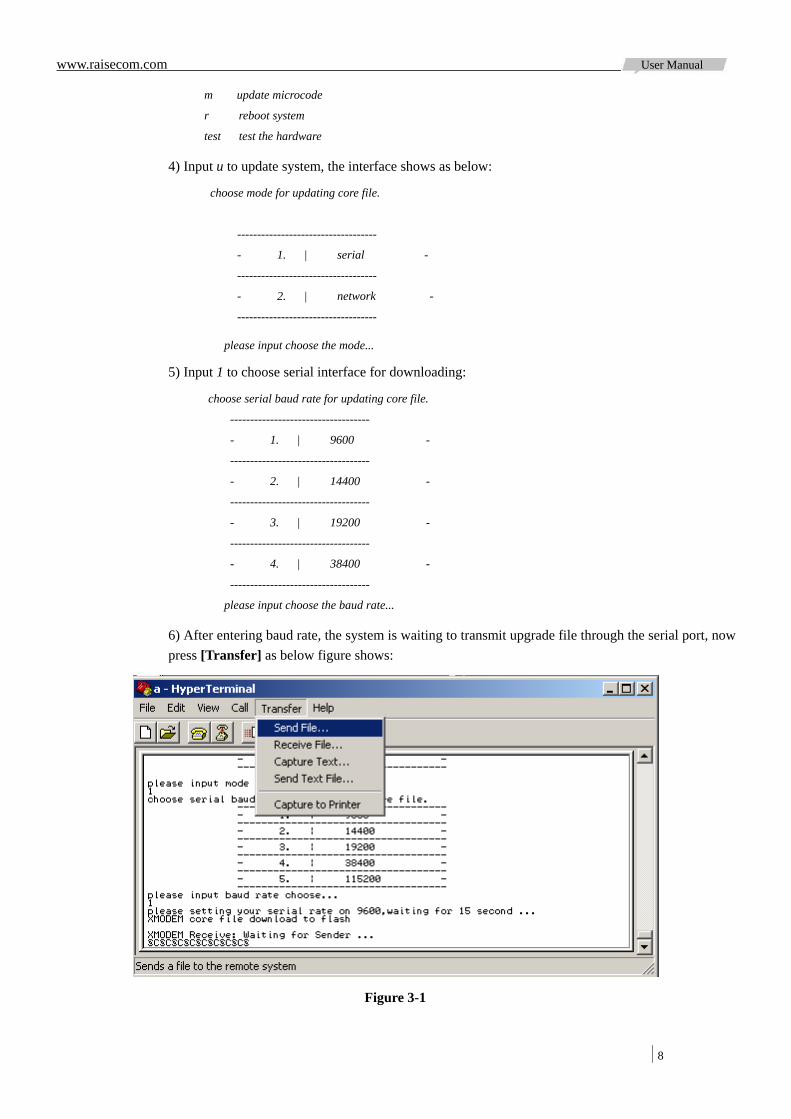
6) After entering baud rate, the system is waiting to transmit upgrade file through the serial port, now press [Transfer] as below figure shows:
Figure 3-1
www.raisecom.com User Manual
9
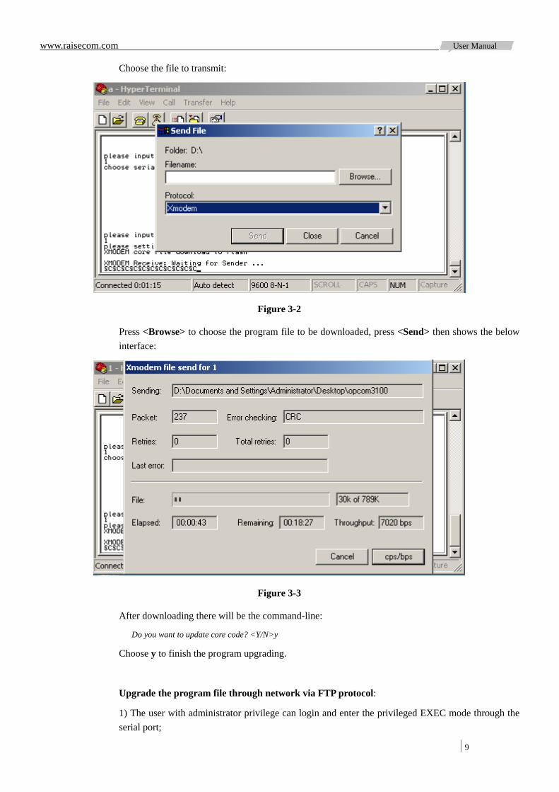
Choose the file to transmit:
Figure 3-2
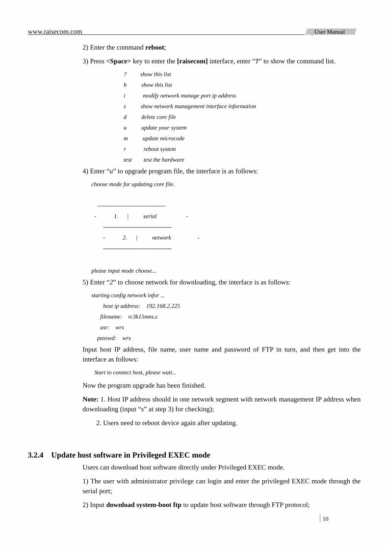
Press <Browse> to choose the program file to be downloaded, press <Send> then shows the below interface:
Figure 3-3
After downloading there will be the command-line:
Do you want to update core code? <Y/N>y
Choose y to finish the program upgrading.
Upgrade the program file through network via FTP protocol:
1) The user with administrator privilege can login and enter the privileged EXEC mode through the serial port;
www.raisecom.com User Manual
10
2) Enter the command reboot;
3) Press <Space> key to enter the [raisecom] interface, enter “?” to show the command list.
? show this list
h show this list
i modify network manage port ip address
s show network management interface information
d delete core file
u update your system
m update microcode
r reboot system
test test the hardware
4) Enter “u” to upgrade program file, the interface is as follows:
choose mode for updating core file.
-----------------------------------
- 1. | serial -
-----------------------------------
- 2. | network -
-----------------------------------
please input mode choose...
5) Enter “2” to choose network for downloading, the interface is as follows:
starting config network infor ...
host ip address: 192.168.2.225
filename: rc3k15nms.z
usr: wrs
passwd: wrs
Input host IP address, file name, user name and password of FTP in turn, and then get into the interface as follows:
Start to connect host, please wait...
Now the program upgrade has been finished.
Note: 1. Host IP address should in one network segment with network management IP address when downloading (input “s” at step 3) for checking);
2. Users need to reboot device again after updating.
3.2.4 Update host software in Privileged EXEC mode Users can download host software directly under Privileged EXEC mode.
1) The user with administrator privilege can login and enter the privileged EXEC mode through the serial port;
2) Input download system-boot ftp to update host software through FTP protocol;
www.raisecom.com User Manual
11
3) Below interface shows after executing the command:
Please input server IP Address : 192.168.4.28
Please input FTP User name : wrs
Please input FTP Password : wrs
Please input FTP Server File Name : rc3kenms.z
Input host IP address, file name, user name and password of FTP in turn, and then get into the interface as follows:
Are you sure[Y/N]:y
Input y to confirm the operation is correct, then shows the below interface:
Loading, please wait...file length = 1884532
Please select the disk for saving image
1. core: 2. exit
Please input the number: 1
Input 1 to choose updating program:
Writing to core disk, please wait...
Copy file successfully!
Please reboot device!
Now the program upgrade from FTP has finished.
Note:
Host IP address should in one network segment with SNMP interface IP address when downloading;
Users need to reboot device again after updating.
3.2.5 Update software of service card from network management card At present, only optical interface uplink card is in support of this function.
1) The user with administrator privilege can login and enter the privileged EXEC mode through the serial port;
2) Input download svcfile system-boot ftp to update host software through FTP protocol;
3) Below interface shows after executing the command:
Please input location of service board : slot 4
Please input server IP Address : 192.168.4.34
Please input FTP User name : wrs
Please input FTP Password : wrs
Please input FTP Server File Name : xxxx.z
Input service card slot ID, host IP address, file name, user name and password of FTP in turn, and then get into the interface as follows:
Are you sure[Y/N]:y
Input y to confirm the operation is correct, then shows the below interface:
Loading file from server to ram, please wait...
www.raisecom.com User Manual
12
File length = 708777
Transmitting file to service board, transmitted 100%
Writing file to flash of service board, please wait...
Write flash about 60s, current waiting 22s
Finished.
Copy file successfully!
Now the single card program upgrade from FTP via network management card has finished.
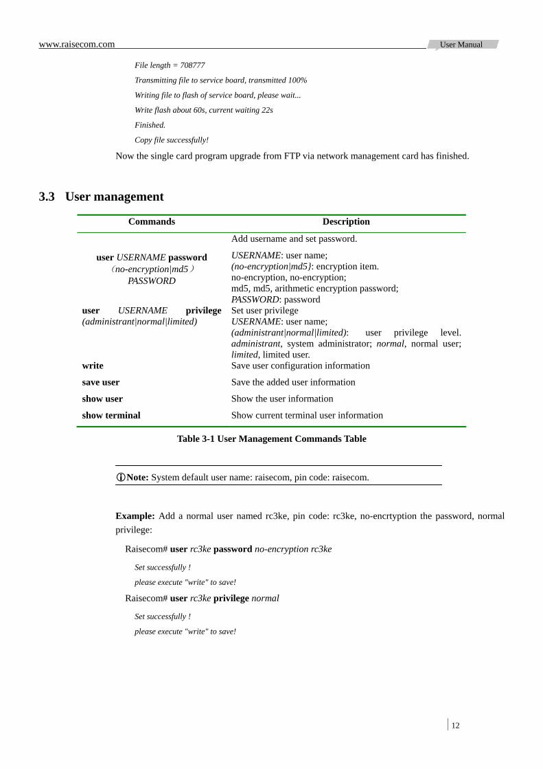
3.3 User management
Commands Description
user USERNAME password (no-encryption|md5)
PASSWORD
Add username and set password.
USERNAME: user name; (no-encryption|md5}: encryption item. no-encryption, no-encryption; md5, md5, arithmetic encryption password; PASSWORD: password
user USERNAME privilege (administrant|normal|limited)
Set user privilege USERNAME: user name; (administrant|normal|limited): user privilege level. administrant, system administrator; normal, normal user; limited, limited user.
write Save user configuration information
save user Save the added user information
show user Show the user information
show terminal Show current terminal user information
Table 3-1 User Management Commands Table
Note: System default user name: raisecom, pin code: raisecom.
Example: Add a normal user named rc3ke, pin code: rc3ke, no-encrtyption the password, normal privilege:
Raisecom# user rc3ke password no-encryption rc3ke
Set successfully !
please execute "write" to save!
Raisecom# user rc3ke privilege normal
Set successfully !
please execute "write" to save!

www.raisecom.com User Manual
13
Chapter 4 Clock Source Configuration
4.1 Overview
RC3000E system clock includes master mode and slave mode. Master mode clock source is internal crystal run; slave mode clock can choose uplink card E1 line sample clock. Default is slave mode uplink E1-1 line sample clock.
Subscriber can assign at most 4 clock sources for selection and set their priority. Selection of clock source has auto-switch mode and manual-switch mode, default to be auto-switch.
Under auto-switch mode, clock module can set as return or non-return mode. In return mode, it always switches to the highest available clock source of current priority, the clock restore time can be set; in non-return mode, only if the current clock source is not local clock and loss of source, it can switch to highest priority available clock source.
Under auto-switch mode, clock module judges whether switch back to highest available source of current priority according to clock source status and setting priority as well as clock return mode; the clock switches to internal crystal running if there is no available clock source currently.
Under manual switch mode, clock module switches clock to assigned clock source and don’t make auto-switch action. If the user assigned source is invalid, clock will be switched to auto mode and choose clock source by auto-switch mode.
4.2 Configure application
Commands Description
config Enter global configuration mode
device clock mode (master|slave) Configure clock mode. Default to be master mode. master: master clock mode; slave: slave clock mode.
device clock e1 <1-8> priority <1-4>
Configure clock priority under master mode; no format command can cancel priority. 1-8: uplink card E1 interface ID; 1-4: priority
device clock restore (enable|disable) Set clock restore mode under auto-mode. enable: restore clock to high priority; disable: the clock works at current clock.
device clock wait-to-restore-time <0-12>
Wait to restore time under clock auto-mode. <0-12>: clock restore time, unit: minute.
device clock manual-switch e1 <1-8>
Force switch clock source under slave mode. 1-8: uplink card E1 interface ID.
no device clock manual-switch Cancel force switch and restore auto-switch mode.
show device clock Show device clock information.
Note: E1 link sample clock may have alarm; users can view configuration priority by the command of show device clock. Some certain single card is not provided with backboard line sample clock, users can view if setting is valid by command show device clock after configuring priority.
www.raisecom.com User Manual
14
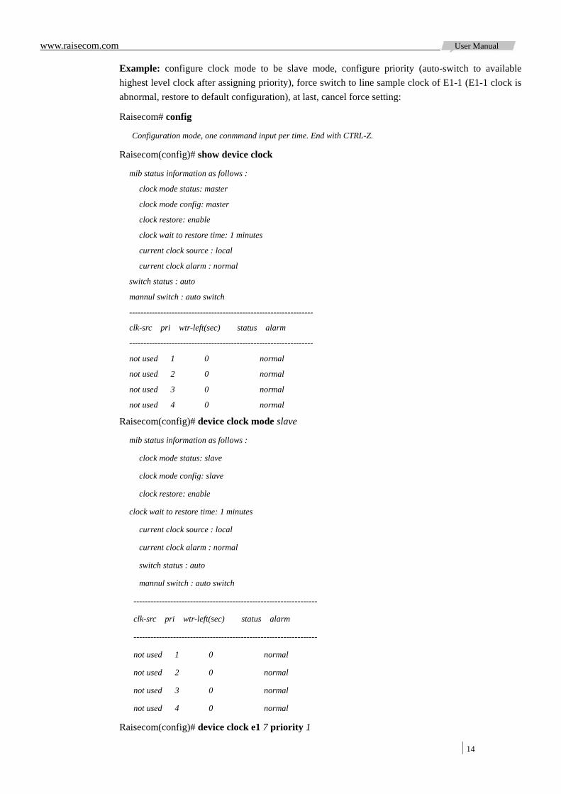
Example: configure clock mode to be slave mode, configure priority (auto-switch to available highest level clock after assigning priority), force switch to line sample clock of E1-1 (E1-1 clock is abnormal, restore to default configuration), at last, cancel force setting:
Raisecom# config
Configuration mode, one conmmand input per time. End with CTRL-Z.
Raisecom(config)# show device clock
mib status information as follows :
clock mode status: master
clock mode config: master
clock restore: enable
clock wait to restore time: 1 minutes
current clock source : local
current clock alarm : normal
switch status : auto
mannul switch : auto switch
-----------------------------------------------------------------
clk-src pri wtr-left(sec) status alarm
-----------------------------------------------------------------
not used 1 0 normal
not used 2 0 normal
not used 3 0 normal
not used 4 0 normal
Raisecom(config)# device clock mode slave
mib status information as follows :
clock mode status: slave
clock mode config: slave
clock restore: enable
clock wait to restore time: 1 minutes
current clock source : local
current clock alarm : normal
switch status : auto
mannul switch : auto switch
-----------------------------------------------------------------
clk-src pri wtr-left(sec) status alarm
-----------------------------------------------------------------
not used 1 0 normal
not used 2 0 normal
not used 3 0 normal
not used 4 0 normal
Raisecom(config)# device clock e1 7 priority 1

www.raisecom.com User Manual
15
Set successfully
Raisecom(config)# device clock e1 6 priority 2
Set successfully
Raisecom(config)# device clock e1 1 priority 4
Set successfully
Raisecom(config)# show device clock
mib status information as follows :
clock mode status: slave
clock mode config: slave
clock restore: enable
clock wait to restore time: 1 minutes
current clock source : line e1 7
current clock alarm : normal
switch status : auto
mannul switch : auto switch
-----------------------------------------------------------------
clk-src pri wtr-left(sec) status alarm
-----------------------------------------------------------------
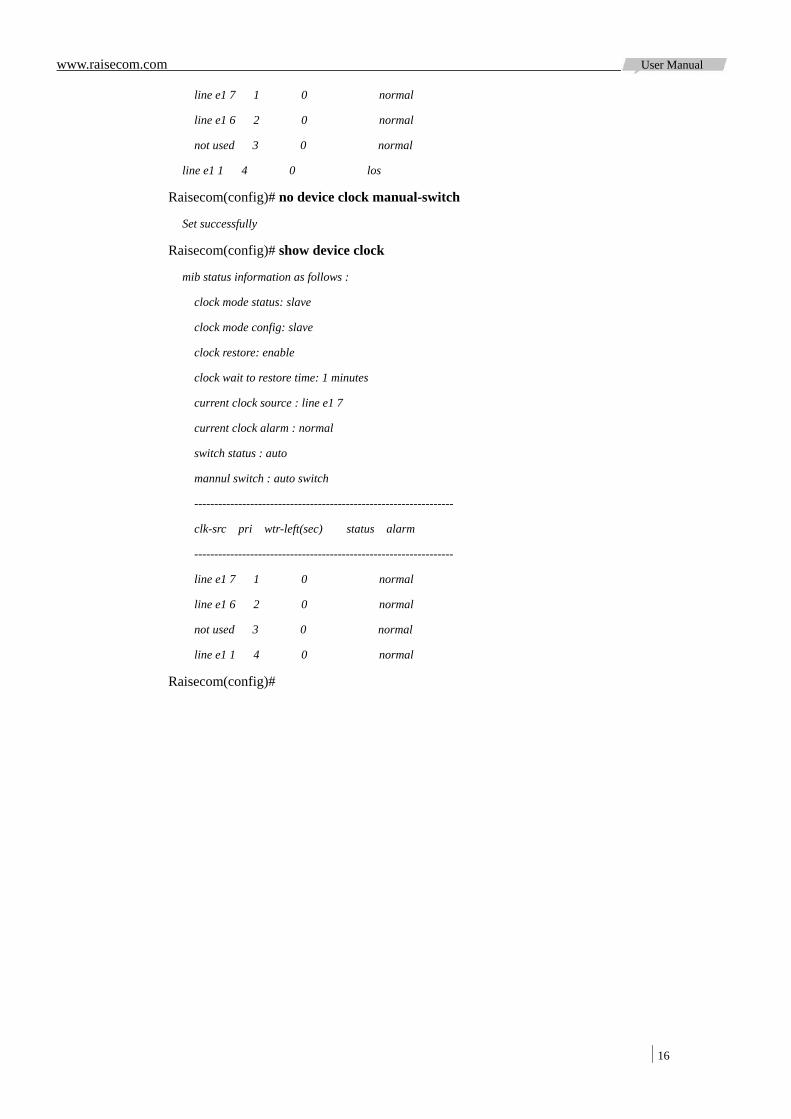
line e1 7 1 0 normal
line e1 6 2 0 normal
not used 3 0 normal
line e1 1 4 0 los
Raisecom(config)# device clock manual-switch e1 1
Set successfully
Raisecom(config)# show de clo
mib status information as follows :
clock mode status: slave
clock mode config: slave
clock restore: enable
clock wait to restore time: 1 minutes
current clock source : line e1 7
current clock alarm : normal
switch status : auto
mannul switch : line e1 1
-----------------------------------------------------------------
clk-src pri wtr-left(sec) status alarm
-----------------------------------------------------------------
www.raisecom.com User Manual
16
line e1 7 1 0 normal
line e1 6 2 0 normal
not used 3 0 normal
line e1 1 4 0 los
Raisecom(config)# no device clock manual-switch
Set successfully
Raisecom(config)# show device clock
mib status information as follows :
clock mode status: slave
clock mode config: slave
clock restore: enable
clock wait to restore time: 1 minutes
current clock source : line e1 7
current clock alarm : normal
switch status : auto
mannul switch : auto switch
-----------------------------------------------------------------
clk-src pri wtr-left(sec) status alarm
-----------------------------------------------------------------
line e1 7 1 0 normal
line e1 6 2 0 normal
not used 3 0 normal
line e1 1 4 0 normal
Raisecom(config)#
www.raisecom.com User Manual
17
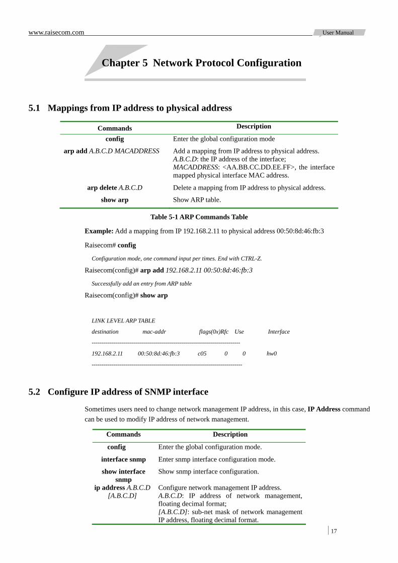
Chapter 5 Network Protocol Configuration
5.1 Mappings from IP address to physical address
Commands Description
config Enter the global configuration mode
arp add A.B.C.D MACADDRESS Add a mapping from IP address to physical address. A.B.C.D: the IP address of the interface; MACADDRESS: <AA.BB.CC.DD.EE.FF>, the interface mapped physical interface MAC address.
arp delete A.B.C.D Delete a mapping from IP address to physical address.
show arp Show ARP table.
Table 5-1 ARP Commands Table
Example: Add a mapping from IP 192.168.2.11 to physical address 00:50:8d:46:fb:3
Raisecom# config
Configuration mode, one command input per times. End with CTRL-Z.
Raisecom(config)# arp add 192.168.2.11 00:50:8d:46:fb:3
Successfully add an entry from ARP table
Raisecom(config)# show arp
LINK LEVEL ARP TABLE
destination mac-addr flags(0x)Rfc Use Interface
--------------------------------------------------------------------------
192.168.2.11 00:50:8d:46:fb:3 c05 0 0 hw0
---------------------------------------------------------------------------
5.2 Configure IP address of SNMP interface
Sometimes users need to change network management IP address, in this case, IP Address command can be used to modify IP address of network management.
Commands Description
config Enter the global configuration mode.
interface snmp Enter snmp interface configuration mode.
show interface snmp
Show snmp interface configuration.
ip address A.B.C.D [A.B.C.D]
Configure network management IP address. A.B.C.D: IP address of network management, floating decimal format; [A.B.C.D]: sub-net mask of network management IP address, floating decimal format.
www.raisecom.com User Manual
18
Table 5-2 SNMP Network Management IP Commands Table
Example: Configure IP of network management to be 192.168.2.20 and sub-net mask to be 255.255.255.0
Raisecom# config
Configuration mode, one command input per times. End with CTRL-Z.
Raisecom (config)#interface snmp
Raisecom (config-snmp)#ip address 192.168.2.20 255.255.255.0
Raisecom (config-snmp)# show interface snmp
Interface:snmp Operation Status :up
Note: IP of network management should be in one network segment with host IP, that is to say, host IP in this example is also in network segment 2.
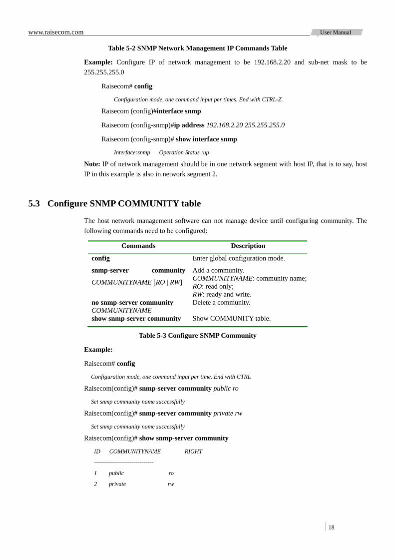
5.3 Configure SNMP COMMUNITY table
The host network management software can not manage device until configuring community. The following commands need to be configured:
Commands Description
config Enter global configuration mode.
snmp-server community
COMMUNITYNAME [RO | RW]
Add a community. COMMUNITYNAME: community name; RO: read only; RW: ready and write.
no snmp-server community COMMUNITYNAME
Delete a community.
show snmp-server community Show COMMUNITY table.
Table 5-3 Configure SNMP Community
Example:
Raisecom# config
Configuration mode, one command input per time. End with CTRL
Raisecom(config)# snmp-server community public ro
Set snmp community name successfully
Raisecom(config)# snmp-server community private rw
Set snmp community name successfully
Raisecom(config)# show snmp-server community
ID COMMUNITYNAME RIGHT
------------------------------
1 public ro
2 private rw
www.raisecom.com User Manual
19
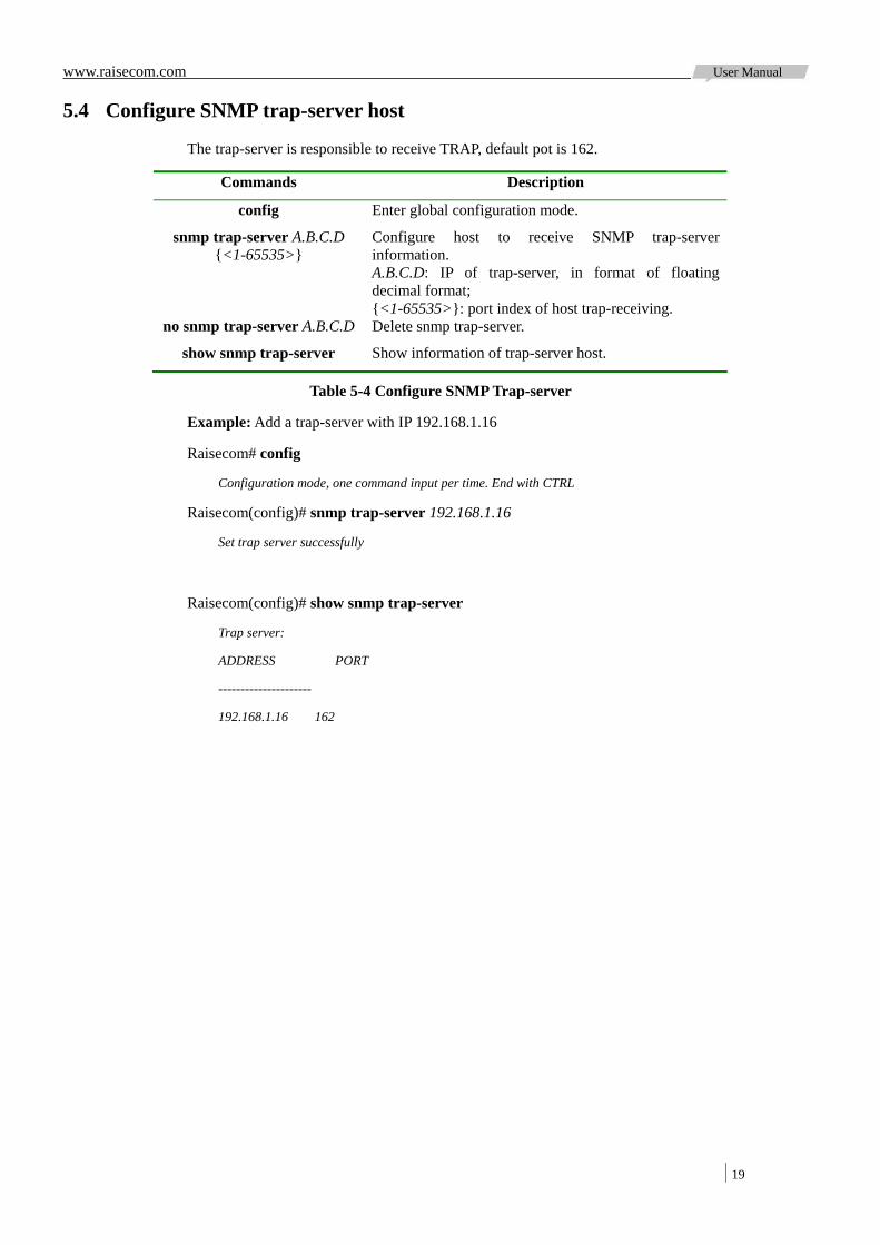
5.4 Configure SNMP trap-server host
The trap-server is responsible to receive TRAP, default pot is 162.
Commands Description
config Enter global configuration mode.
snmp trap-server A.B.C.D {<1-65535>}
Configure host to receive SNMP trap-server information. A.B.C.D: IP of trap-server, in format of floating decimal format; {<1-65535>}: port index of host trap-receiving.
no snmp trap-server A.B.C.D Delete snmp trap-server.
show snmp trap-server Show information of trap-server host.
Table 5-4 Configure SNMP Trap-server
Example: Add a trap-server with IP 192.168.1.16
Raisecom# config
Configuration mode, one command input per time. End with CTRL
Raisecom(config)# snmp trap-server 192.168.1.16
Set trap server successfully
Raisecom(config)# show snmp trap-server
Trap server:
ADDRESS PORT
---------------------
192.168.1.16 162
www.raisecom.com User Manual
20
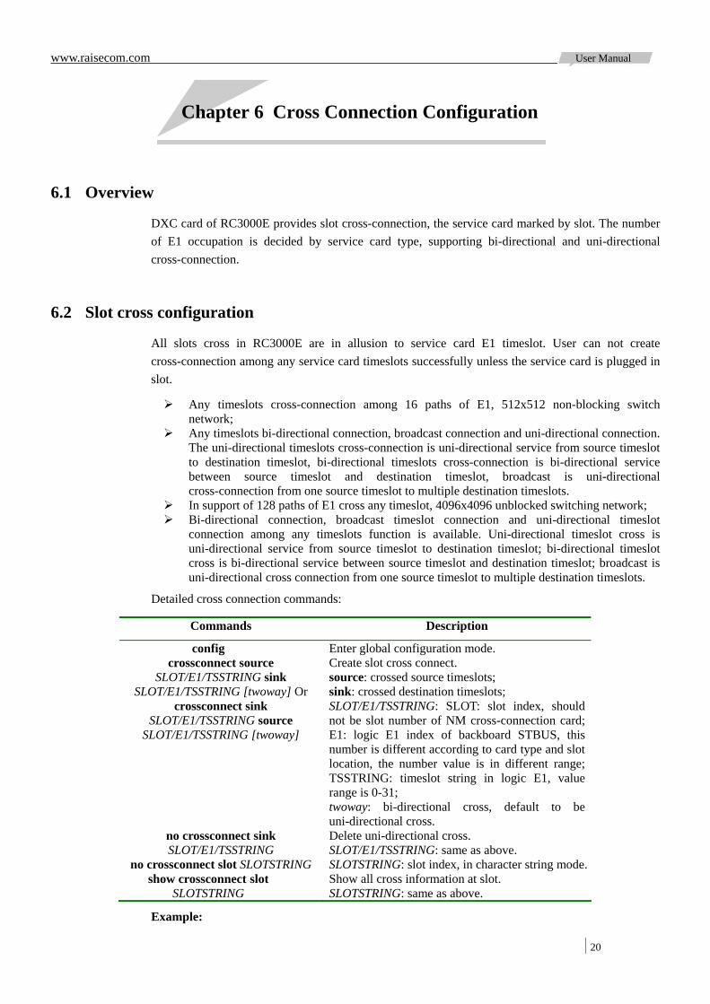
Chapter 6 Cross Connection Configuration
6.1 Overview
DXC card of RC3000E provides slot cross-connection, the service card marked by slot. The number of E1 occupation is decided by service card type, supporting bi-directional and uni-directional cross-connection.
6.2 Slot cross configuration
All slots cross in RC3000E are in allusion to service card E1 timeslot. User can not create cross-connection among any service card timeslots successfully unless the service card is plugged in slot.
Any timeslots cross-connection among 16 paths of E1, 512x512 non-blocking switch network;
Any timeslots bi-directional connection, broadcast connection and uni-directional connection. The uni-directional timeslots cross-connection is uni-directional service from source timeslot to destination timeslot, bi-directional timeslots cross-connection is bi-directional service between source timeslot and destination timeslot, broadcast is uni-directional cross-connection from one source timeslot to multiple destination timeslots.
In support of 128 paths of E1 cross any timeslot, 4096x4096 unblocked switching network; Bi-directional connection, broadcast timeslot connection and uni-directional timeslot
connection among any timeslots function is available. Uni-directional timeslot cross is uni-directional service from source timeslot to destination timeslot; bi-directional timeslot cross is bi-directional service between source timeslot and destination timeslot; broadcast is uni-directional cross connection from one source timeslot to multiple destination timeslots.
Detailed cross connection commands:
Commands Description
config Enter global configuration mode. crossconnect source
SLOT/E1/TSSTRING sink SLOT/E1/TSSTRING [twoway] Or
crossconnect sink SLOT/E1/TSSTRING source
SLOT/E1/TSSTRING [twoway]
Create slot cross connect. source: crossed source timeslots; sink: crossed destination timeslots; SLOT/E1/TSSTRING: SLOT: slot index, should not be slot number of NM cross-connection card; E1: logic E1 index of backboard STBUS, this number is different according to card type and slot location, the number value is in different range; TSSTRING: timeslot string in logic E1, value range is 0-31; twoway: bi-directional cross, default to be uni-directional cross.
no crossconnect sink SLOT/E1/TSSTRING
Delete uni-directional cross. SLOT/E1/TSSTRING: same as above.
no crossconnect slot SLOTSTRING SLOTSTRING: slot index, in character string mode.show crossconnect slot
SLOTSTRING Show all cross information at slot. SLOTSTRING: same as above.
Example:
www.raisecom.com User Manual
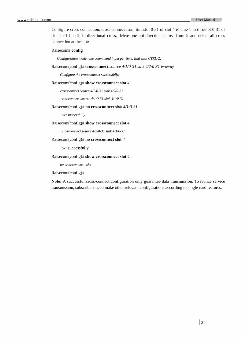
21
Configure cross connection, cross connect from timeslot 0-31 of slot 4 e1 line 1 to timeslot 0-31 of slot 4 e1 line 2, bi-directional cross, delete one uni-directional cross from it and delete all cross connection at the slot:
Raisecom# config
Configuration mode, one conmmand input per time. End with CTRL-Z.
Raisecom(config)# crossconnect source 4/1/0-31 sink 4/2/0-31 twoway
Configure the crossconnect successfully.
Raisecom(config)# show crossconnect slot 4
crossconnect source 4/2/0-31 sink 4/2/0-31
crossconnect source 4/1/0-31 sink 4/1/0-31
Raisecom(config)# no crossconnect sink 4/1/0-31
Set successfully
Raisecom(config)# show crossconnect slot 4
crossconnect source 4/2/0-31 sink 4/1/0-31
Raisecom(config)# no crossconnect slot 4
Set successfully
Raisecom(config)# show crossconnect slot 4
no crossconnect exist
Raisecom(config)#
Note: A successful cross-connect configuration only guarantee data transmission. To realize service transmission, subscribers need make other relevant configurations according to single card features.
www.raisecom.com User Manual
22
Chapter 7 Uplink Card Protection Switch Configuration
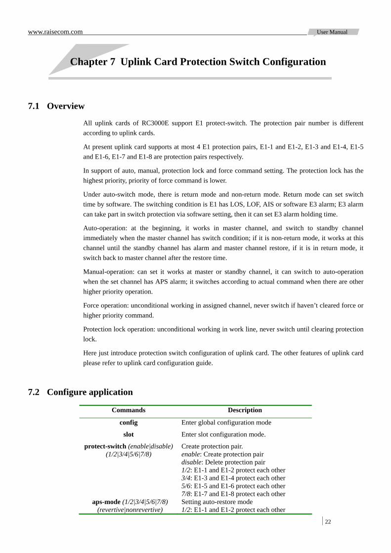
7.1 Overview
All uplink cards of RC3000E support E1 protect-switch. The protection pair number is different according to uplink cards.
At present uplink card supports at most 4 E1 protection pairs, E1-1 and E1-2, E1-3 and E1-4, E1-5 and E1-6, E1-7 and E1-8 are protection pairs respectively.
In support of auto, manual, protection lock and force command setting. The protection lock has the highest priority, priority of force command is lower.
Under auto-switch mode, there is return mode and non-return mode. Return mode can set switch time by software. The switching condition is E1 has LOS, LOF, AIS or software E3 alarm; E3 alarm can take part in switch protection via software setting, then it can set E3 alarm holding time.
Auto-operation: at the beginning, it works in master channel, and switch to standby channel immediately when the master channel has switch condition; if it is non-return mode, it works at this channel until the standby channel has alarm and master channel restore, if it is in return mode, it switch back to master channel after the restore time.
Manual-operation: can set it works at master or standby channel, it can switch to auto-operation when the set channel has APS alarm; it switches according to actual command when there are other higher priority operation.
Force operation: unconditional working in assigned channel, never switch if haven’t cleared force or higher priority command.
Protection lock operation: unconditional working in work line, never switch until clearing protection lock.
Here just introduce protection switch configuration of uplink card. The other features of uplink card please refer to uplink card configuration guide.
7.2 Configure application
Commands Description
config Enter global configuration mode
slot Enter slot configuration mode.
protect-switch (enable|disable) (1/2|3/4|5/6|7/8)
Create protection pair. enable: Create protection pair disable: Delete protection pair 1/2: E1-1 and E1-2 protect each other 3/4: E1-3 and E1-4 protect each other 5/6: E1-5 and E1-6 protect each other 7/8: E1-7 and E1-8 protect each other
aps-mode (1/2|3/4|5/6|7/8) (revertive|nonrevertive)
Setting auto-restore mode 1/2: E1-1 and E1-2 protect each other

www.raisecom.com User Manual
23
3/4: E1-3 and E1-4 protect each other 5/6: E1-5 and E1-6 protect each other 7/8: E1-7 and E1-8 protect each other revertive: restore to work line mode nonrevertive: don’t restore to work line
aps-restore-time (1/2|3/4|5/6|7/8) <0-12>
Setting auto-restore time. 1/2: E1-1 and E1-2 protect each other 3/4: E1-3 and E1-4 protect each other 5/6: E1-5 and E1-6 protect each other 7/8: E1-7 and E1-8 protect each other <0-12>: auto-restore time, unit: minute
force-switch (1/2|3/4|5/6|7/8) (work-line|protection-line|clear)
Setting force switch command 1/2: E1-1 and E1-2 protect each other 3/4: E1-3 and E1-4 protect each other 5/6: E1-5 and E1-6 protect each other 7/8: E1-7 and E1-8 protect each other work-line: force to work line protection-line: force to protection line clear: clear force switch
show aps Show protect-switch configuration and status.
Example: Create protection pair E1-3 and E1-4, auto-switch mode is return mode, restore time is 5 minutes; force protection pair works on protection channel, clear force command and delete protection pair:
Raisecom# config
Configuration mode, one conmmand input per time. End with CTRL-Z.
Raisecom(config)# slot 4
Raisecom(config-slot/4)# protect-switch enable 3/4
Set successfully
Raisecom(config-slot/4)# show aps
-------------------------------------------------------------
psId exist workLine protectLine activeLine swStatus
1 no 1 2 working aps-switch
Aps-revertive-mode revertive-time-left Aps-e3-sf
12(m) 0(s) disable
-------------------------------------------------------------
psId exist workLine protectLine activeLine swStatus
2 yes 3 4 working aps-switch
Aps-revertive-mode revertive-time-left Aps-e3-sf
12(m) 0(s) disable
Raisecom(config-slot/4)# aps-mode 3/4 revertive
Set successfully
Raisecom(config-slot/4)# aps-restore-time 3/4 5
Set successfully
Raisecom(config-slot/4)# show aps
www.raisecom.com User Manual
24
-------------------------------------------------------------
psId exist workLine protectLine activeLine swStatus
1 no 1 2 working aps-switch
Aps-revertive-mode revertive-time-left Aps-e3-sf
12(m) 0(s) disable
-------------------------------------------------------------
psId exist workLine protectLine activeLine swStatus
2 yes 3 4 working aps-switch
Aps-revertive-mode revertive-time-left Aps-e3-sf
5(m) 0(s) 6(s)
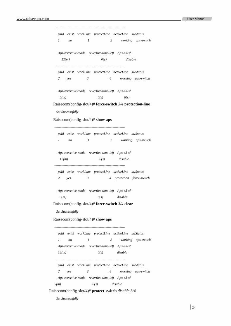
Raisecom(config-slot/4)# force-switch 3/4 protection-line
Set Successfully
Raisecom(config-slot/4)# show aps
-------------------------------------------------------------
psId exist workLine protectLine activeLine swStatus
1 no 1 2 working aps-switch
Aps-revertive-mode revertive-time-left Aps-e3-sf
12(m) 0(s) disable
-------------------------------------------------------------
psId exist workLine protectLine activeLine swStatus
2 yes 3 4 protection force-switch
Aps-revertive-mode revertive-time-left Aps-e3-sf
5(m) 0(s) disable
Raisecom(config-slot/4)# force-switch 3/4 clear
Set Successfully
Raisecom(config-slot/4)# show aps
-------------------------------------------------------------
psId exist workLine protectLine activeLine swStatus
1 no 1 2 working aps-switch
Aps-revertive-mode revertive-time-left Aps-e3-sf
12(m) 0(s) disable
-------------------------------------------------------------
psId exist workLine protectLine activeLine swStatus
2 yes 3 4 working aps-switch
Aps-revertive-mode revertive-time-left Aps-e3-sf
5(m) 0(s) disable
Raisecom(config-slot/4)# protect-switch disable 3/4
Set Successfully
www.raisecom.com User Manual
25
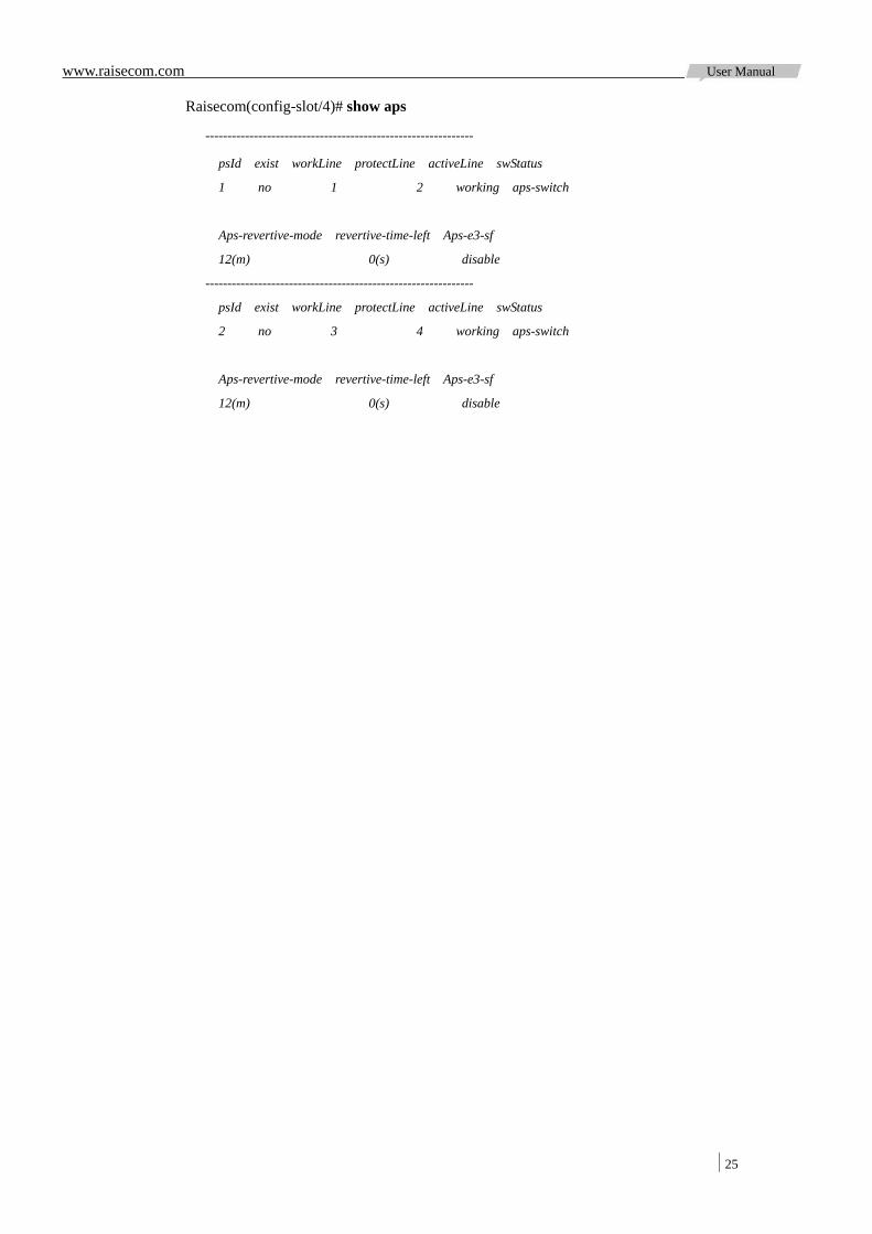
Raisecom(config-slot/4)# show aps
-------------------------------------------------------------
psId exist workLine protectLine activeLine swStatus
1 no 1 2 working aps-switch
Aps-revertive-mode revertive-time-left Aps-e3-sf
12(m) 0(s) disable
-------------------------------------------------------------
psId exist workLine protectLine activeLine swStatus
2 no 3 4 working aps-switch
Aps-revertive-mode revertive-time-left Aps-e3-sf
12(m) 0(s) disable
www.raisecom.com User Manual
26
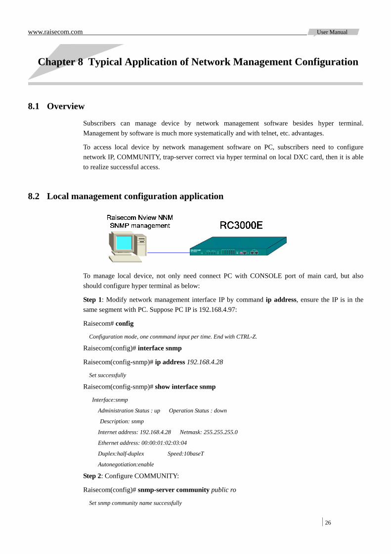
Chapter 8 Typical Application of Network Management Configuration
8.1 Overview
Subscribers can manage device by network management software besides hyper terminal. Management by software is much more systematically and with telnet, etc. advantages.
To access local device by network management software on PC, subscribers need to configure network IP, COMMUNITY, trap-server correct via hyper terminal on local DXC card, then it is able to realize successful access.
8.2 Local management configuration application
To manage local device, not only need connect PC with CONSOLE port of main card, but also should configure hyper terminal as below:
Step 1: Modify network management interface IP by command ip address, ensure the IP is in the same segment with PC. Suppose PC IP is 192.168.4.97:
Raisecom# config
Configuration mode, one conmmand input per time. End with CTRL-Z.
Raisecom(config)# interface snmp
Raisecom(config-snmp)# ip address 192.168.4.28
Set successfully
Raisecom(config-snmp)# show interface snmp
Interface:snmp
Administration Status : up Operation Status : down
Description: snmp
Internet address: 192.168.4.28 Netmask: 255.255.255.0
Ethernet address: 00:00:01:02:03:04
Duplex:half-duplex Speed:10baseT
Autonegotiation:enable
Step 2: Configure COMMUNITY:
Raisecom(config)# snmp-server community public ro
Set snmp community name successfully
www.raisecom.com User Manual
27
Raisecom(config)# snmp-server community private rw
Set snmp community name successfully
Raisecom(config)# show snmp-server community
ID COMMUNITYNAME RIGHT
------------------------------
1 public ro
2 private rw
Step 3: Set trap-server host:
Raisecom(config)# snmp trap-server 192.168.4.97
Set trap server successfully
Raisecom(config)# show snmp trap-server
Trap server:
ADDRESS PORT
----------------------------------------
192.168.4.97 162
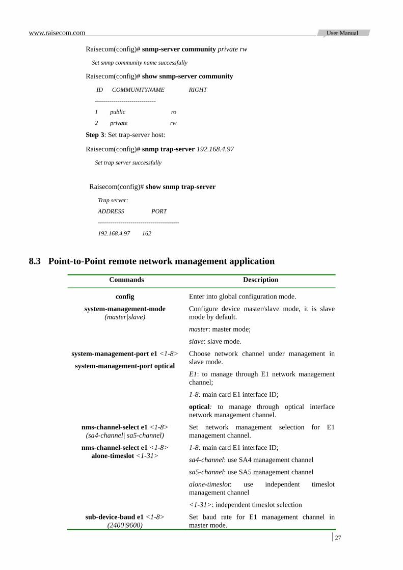
8.3 Point-to-Point remote network management application
Commands Description
config Enter into global configuration mode.
system-management-mode (master|slave)
Configure device master/slave mode, it is slave mode by default.
master: master mode;
slave: slave mode.
system-management-port e1 <1-8>
system-management-port optical
Choose network channel under management in slave mode.
E1: to manage through E1 network management channel;
1-8: main card E1 interface ID;
optical: to manage through optical interface network management channel.
nms-channel-select e1 <1-8> (sa4-channel| sa5-channel)
nms-channel-select e1 <1-8> alone-timeslot <1-31>
Set network management selection for E1 management channel.
1-8: main card E1 interface ID;
sa4-channel: use SA4 management channel
sa5-channel: use SA5 management channel
alone-timeslot: use independent timeslot management channel
<1-31>: independent timeslot selection
sub-device-baud e1 <1-8> (2400|9600)
Set baud rate for E1 management channel in master mode.
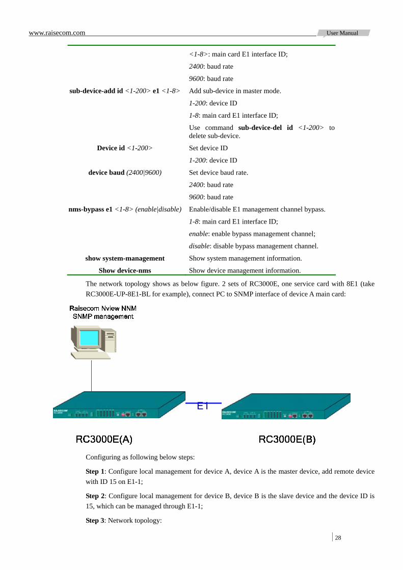
www.raisecom.com User Manual
28
<1-8>: main card E1 interface ID;
2400: baud rate
9600: baud rate
sub-device-add id <1-200> e1 <1-8> Add sub-device in master mode.
1-200: device ID
1-8: main card E1 interface ID;
Use command sub-device-del id <1-200> to delete sub-device.
Device id <1-200> Set device ID
1-200: device ID
device baud (2400|9600) Set device baud rate.
2400: baud rate
9600: baud rate
nms-bypass e1 <1-8> (enable|disable) Enable/disable E1 management channel bypass.
1-8: main card E1 interface ID;
enable: enable bypass management channel;
disable: disable bypass management channel.
show system-management Show system management information.
Show device-nms Show device management information.
The network topology shows as below figure. 2 sets of RC3000E, one service card with 8E1 (take RC3000E-UP-8E1-BL for example), connect PC to SNMP interface of device A main card:
E1
Configuring as following below steps:
Step 1: Configure local management for device A, device A is the master device, add remote device with ID 15 on E1-1;
Step 2: Configure local management for device B, device B is the slave device and the device ID is 15, which can be managed through E1-1;
Step 3: Network topology:
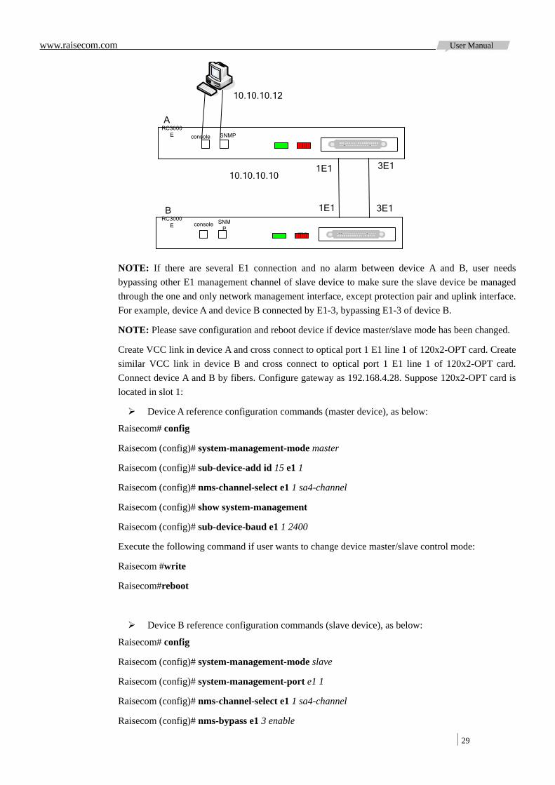
www.raisecom.com User Manual
29
Bconsole SNM
P
RC3000E
console SNMPRC3000
E
A
10.10.10.12
10.10.10.101E1
1E1 3E1
3E1
NOTE: If there are several E1 connection and no alarm between device A and B, user needs bypassing other E1 management channel of slave device to make sure the slave device be managed through the one and only network management interface, except protection pair and uplink interface. For example, device A and device B connected by E1-3, bypassing E1-3 of device B.
NOTE: Please save configuration and reboot device if device master/slave mode has been changed.
Create VCC link in device A and cross connect to optical port 1 E1 line 1 of 120x2-OPT card. Create similar VCC link in device B and cross connect to optical port 1 E1 line 1 of 120x2-OPT card. Connect device A and B by fibers. Configure gateway as 192.168.4.28. Suppose 120x2-OPT card is located in slot 1:
Device A reference configuration commands (master device), as below:
Raisecom# config
Raisecom (config)# system-management-mode master
Raisecom (config)# sub-device-add id 15 e1 1
Raisecom (config)# nms-channel-select e1 1 sa4-channel
Raisecom (config)# show system-management
Raisecom (config)# sub-device-baud e1 1 2400
Execute the following command if user wants to change device master/slave control mode:
Raisecom #write
Raisecom#reboot
Device B reference configuration commands (slave device), as below:
Raisecom# config
Raisecom (config)# system-management-mode slave
Raisecom (config)# system-management-port e1 1
Raisecom (config)# nms-channel-select e1 1 sa4-channel
Raisecom (config)# nms-bypass e1 3 enable
www.raisecom.com User Manual
30
Raisecom (config)# show system-management
Raisecom (config)#device id 15
Raisecom (config)# device baud 2400
Raisecom (config)#show device-nms
Execute the following command if user wants to change device master/slave control mode:
Raisecom # write
Raisecom# reboot
After successful configuration, device A can manage device.
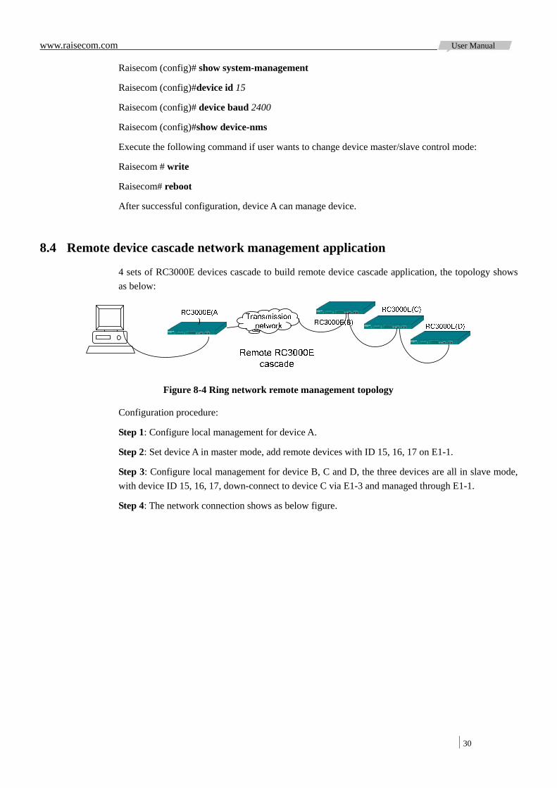
8.4 Remote device cascade network management application
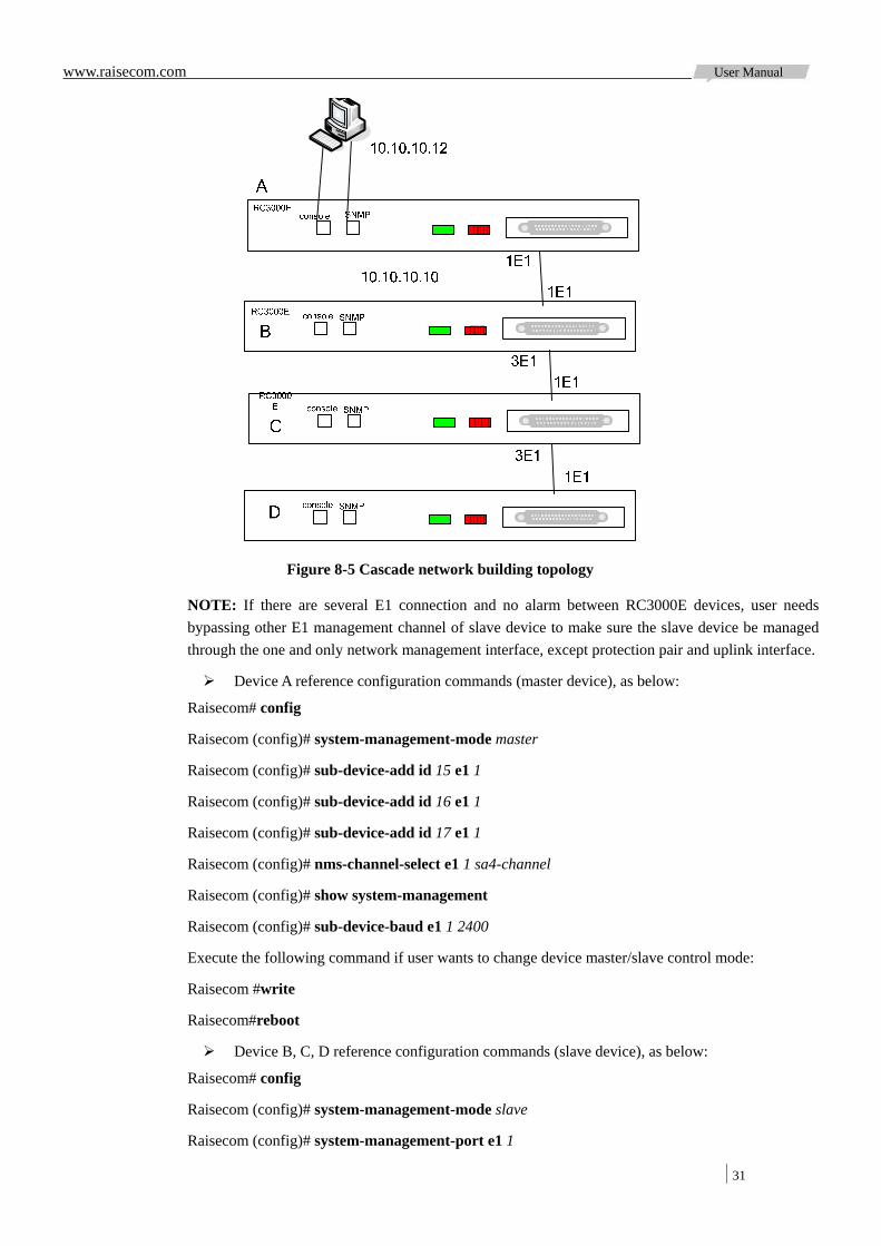
4 sets of RC3000E devices cascade to build remote device cascade application, the topology shows as below:
Figure 8-4 Ring network remote management topology
Configuration procedure:
Step 1: Configure local management for device A.
Step 2: Set device A in master mode, add remote devices with ID 15, 16, 17 on E1-1.
Step 3: Configure local management for device B, C and D, the three devices are all in slave mode, with device ID 15, 16, 17, down-connect to device C via E1-3 and managed through E1-1.
Step 4: The network connection shows as below figure.
www.raisecom.com User Manual
31
Figure 8-5 Cascade network building topology
NOTE: If there are several E1 connection and no alarm between RC3000E devices, user needs bypassing other E1 management channel of slave device to make sure the slave device be managed through the one and only network management interface, except protection pair and uplink interface.
Device A reference configuration commands (master device), as below:
Raisecom# config
Raisecom (config)# system-management-mode master
Raisecom (config)# sub-device-add id 15 e1 1
Raisecom (config)# sub-device-add id 16 e1 1
Raisecom (config)# sub-device-add id 17 e1 1
Raisecom (config)# nms-channel-select e1 1 sa4-channel
Raisecom (config)# show system-management
Raisecom (config)# sub-device-baud e1 1 2400
Execute the following command if user wants to change device master/slave control mode:
Raisecom #write
Raisecom#reboot
Device B, C, D reference configuration commands (slave device), as below:
Raisecom# config
Raisecom (config)# system-management-mode slave
Raisecom (config)# system-management-port e1 1
www.raisecom.com User Manual
32
Raisecom (config)# nms-channel-select e1 1 sa4-channel
Raisecom (config)# nms-channel-select e1 3 sa4-channel
Raisecom (config)# nms-bypass e1 2 enable
Raisecom (config)# nms-bypass e1 4 enable
Raisecom (config)# nms-bypass e1 5 enable
Raisecom (config)# nms-bypass e1 6 enable
Raisecom (config)# nms-bypass e1 7 enable
Raisecom (config)# nms-bypass e1 8 enable
Raisecom (config)# show system-management
Raisecom (config)#device id 15 (set device C as 16, device D as 17)
Raisecom (config)# device baud 2400
Raisecom (config)#show device-nms
Execute the following command if user wants to change device master/slave control mode:
Raisecom # write
Raisecom# reboot
After successful configuration, device A can manage device B, C and D.
8.5 SA data transparent transmission management application
Device A can manage device C via RC3000E-B, which building RC3000E SA data transparent transmission. Device A can be RC3000-15+8E1, RC3000E or device from other vendors, device C can be RC3000E, RC3000, RC3101 or device from other vendors.
Example: Device A is RC3000E-A, device B is RC3000E-B, device C is RC3000E-C, the topology of devices shows as below:

www.raisecom.com User Manual
33
Figure 8-6 Ring network remote management topology
The configuration procedure:
Step 1: Configure local management for device A.
Step 2: Set device A in master mode, add remote device with ID 15 on E1-1.
Step 3: Set device B in slave mode, with device ID 10, down-connect to device C via E1-3.
Step 4: Set device C in slave mode, with device ID 15.
Device A reference configuration commands (slave device), as below:
Raisecom# config
Raisecom (config)# system-management-mode master
Raisecom (config)# sub-device-add id 15 e1 1
Raisecom (config)# nms-channel-select e1 1 sa4-channel
Raisecom (config)# show system-management
Raisecom (config)# sub-device-baud e1 1 2400
Execute the following command if user wants to change device master/slave control mode:
Raisecom #write
Raisecom#reboot
Device B reference configuration commands (slave device), as below:
Raisecom# config
Raisecom (config)# system-management-mode slave
Raisecom (config)# nms-channel-select e1 1 sa4-channel
Raisecom (config)# nms-channel-select e1 3 sa4-channel

www.raisecom.com User Manual
34
Raisecom (config)# nms-bypass e1 1 enable
Raisecom (config)# nms-bypass e1 3 enable
Raisecom (config)# show system-management
Raisecom (config)#device id 10
Raisecom (config)# device baud 2400
Raisecom (config)#show device-nms
Raisecom (config)# crossconnect source 4/1/0 sink 4/3/0 twoway
Execute the following command if user wants to change device master/slave control mode:
Raisecom # write
Raisecom# reboot
Device C reference configuration commands (slave device), as below:
Raisecom# config
Raisecom (config)# system-management-mode slave
Raisecom (config)# nms-channel-select e1 1 sa4-channel
Raisecom (config)# show system-management
Raisecom (config)#device id 15
Raisecom (config)# device baud 2400
Raisecom (config)#show device-nms
Execute the following command if user wants to change device master/slave control mode:
Raisecom # write
Raisecom# reboot
After successful configuration, device A can manage device C but can not manage device B.

www.raisecom.com User Manual
35
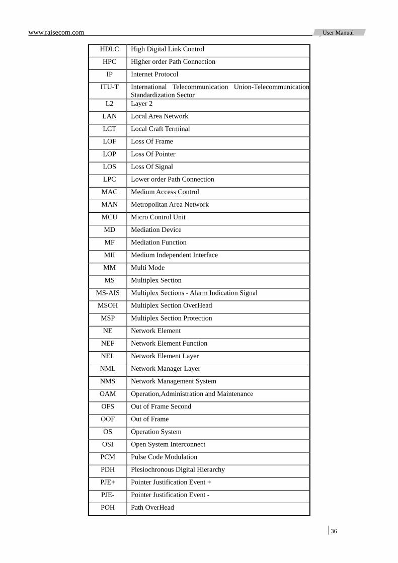
Appendix A Acronyms
Acronyms Full-spelling
ADM Add-Drop Multiplexer
AIS Alarm Indication Signal
APS Automatic Protection Switching
AU Administrative Unit
AU-n Administration Unit,level n
AUG Administration Unit Group
AU-PTR Administration Unit Pointer
BBE Background Block Error
BBER Background Block Error Ratio
BER Bit Error Ratio
CMI Coded Mark Inversion
C-n Container- n
CORBA Common Object Request Broker Architecture
CV Code Violation
DCC Data Communications Channel
DCE Data Circuit-terminating Equipment
DCF Data Communications Function
DCN Data Communications Network
DDN Digital Data Network
DTE Data Terminal Equipment
DXC Digital Cross Connect
ECC Embedded Control Channel
EM Element Management
EML Element Management Layer
EMS Element Management System
EOS Ethernet Over SDH
ES Error Second
ESR Error Second Ratio
ETSI European Telecommunication Standards Institute
FEBBE Far End Background Block Error
FEES Far End Error Second
FESES Far End Severely Error Second
GUI Graphical User Interface
www.raisecom.com User Manual
36
HDLC High Digital Link Control
HPC Higher order Path Connection
IP Internet Protocol
ITU-T International Telecommunication Union-TelecommunicationStandardization Sector
L2 Layer 2
LAN Local Area Network
LCT Local Craft Terminal
LOF Loss Of Frame
LOP Loss Of Pointer
LOS Loss Of Signal
LPC Lower order Path Connection
MAC Medium Access Control
MAN Metropolitan Area Network
MCU Micro Control Unit
MD Mediation Device
MF Mediation Function
MII Medium Independent Interface
MM Multi Mode
MS Multiplex Section
MS-AIS Multiplex Sections - Alarm Indication Signal
MSOH Multiplex Section OverHead
MSP Multiplex Section Protection
NE Network Element
NEF Network Element Function
NEL Network Element Layer
NML Network Manager Layer
NMS Network Management System
OAM Operation,Administration and Maintenance
OFS Out of Frame Second
OOF Out of Frame
OS Operation System
OSI Open System Interconnect
PCM Pulse Code Modulation
PDH Plesiochronous Digital Hierarchy
PJE+ Pointer Justification Event +
PJE- Pointer Justification Event -
POH Path OverHead

www.raisecom.com User Manual
37
PPP Point to Point Protocol
PRC Primary Reference Clock
RAM Random Access Memory
RDI Remote Defect Indication
REI Remote Error Indication
REG Regenerator
RFI Remote Failure Indication
RIP Router Information Protocol
RMII Reduced Medium Independent Interface
RS Regenerator Section
RSOH Regenerator Section OverHead
SDH Synchronous Digital Hierarchy
SEC SDH Equipment Clock
SES Severely Error Second
SESR Severely Error Second Ratio
SETS Synchronous Equipment Timing Source
SM Single Mode
SNCP Sub network Connection Protection
SOH Section Overhead
SPRING Shared Protection Ring
SSM Synchronous State Message
STM-N Synchronous Transport Module Level-N
TCP Transport Control Protocol
TDEV Time Deviation
TDM Time Division Multiplex
TM Terminal Multiplexer
TMN Telecommunications Management Network
TU Tributary Unit
TU-m Tributary Unit,level m
TUG-m Tributary Unit Group, level m
UAS Unavailable Second
VC Virtual Container
VC-n Virtual Container, level n
VLAN Virtual Local Area Network
WAN Wide Area Network

Address: Building 2, No. 28 of the Shangdi 6th Street, Haidian District, Beijing. Postcode: 100085 Tel: +86-10-82883305 Fax: +86-10-82883056 Email: [email protected] http://www.raisecom.com