
PCI BIOS SPECIFICATION - O3ONE PCI devices in a host computer without any knowledge of how the...
28
PCI BIOS SPECIFICATION Revision 2.1 August 26, 1994
Transcript of PCI BIOS SPECIFICATION - O3ONE PCI devices in a host computer without any knowledge of how the...

PCI BIOS SPECIFICATION
Revision 2.1
August 26, 1994
ii PCI BIOS Specification Revision 2.1
Copyright PCI Special Interest Group
REVISION REVISION HISTORY DATE
1.0 Original issue distributed by Intel 9/28/92
2.0 Updated to be in synch with PCI Bus Specification Rev2.0
7/20/93
2.1 Added functions for PCI IRQ routing; Clarifications. 8/26/94
The PCI Special Interest Group disclaims all warranties and liability for the use of thisdocument and the information contained herein and assumes no responsibility for anyerrors that may appear in this document, nor does the PCI Special Interest Group make acommitment to update the information contained herein.
Contact the PCI Special Interest Group office to obtain the latest revision of thespecification.
Questions regarding the PCI BIOS specification or membership in the PCI SpecialInterest Group may be forwarded to:
PCI Special Interest Group2575 NE Kathryn St #17
Hillsboro, OR 97124(800) 433-5177 - Domestic
(503) 693-6232 - International(503) 693-8344 - [email protected]
Revision 2.1 PCI BIOS Specification iii
Copyright PCI Special Interest Group
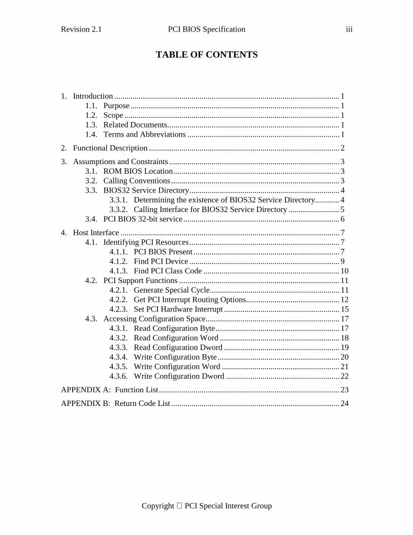
TABLE OF CONTENTS
1. Introduction ............................................................................................................... 11.1. Purpose ....................................................................................................... 11.2. Scope .......................................................................................................... 11.3. Related Documents..................................................................................... 11.4. Terms and Abbreviations ........................................................................... 1
2. Functional Description .............................................................................................. 2
3. Assumptions and Constraints .................................................................................... 33.1. ROM BIOS Location.................................................................................. 33.2. Calling Conventions ................................................................................... 33.3. BIOS32 Service Directory.......................................................................... 4
3.3.1. Determining the existence of BIOS32 Service Directory............ 43.3.2. Calling Interface for BIOS32 Service Directory ......................... 5
3.4. PCI BIOS 32-bit service............................................................................. 6
4. Host Interface ............................................................................................................ 74.1. Identifying PCI Resources.......................................................................... 7
4.1.1. PCI BIOS Present ........................................................................ 74.1.2. Find PCI Device .......................................................................... 94.1.3. Find PCI Class Code ................................................................... 10
4.2. PCI Support Functions ............................................................................... 114.2.1. Generate Special Cycle................................................................ 114.2.2. Get PCI Interrupt Routing Options.............................................. 124.2.3. Set PCI Hardware Interrupt ......................................................... 15
4.3. Accessing Configuration Space.................................................................. 174.3.1. Read Configuration Byte............................................................. 174.3.2. Read Configuration Word ........................................................... 184.3.3. Read Configuration Dword ......................................................... 194.3.4. Write Configuration Byte ............................................................ 204.3.5. Write Configuration Word .......................................................... 214.3.6. Write Configuration Dword ........................................................ 22
APPENDIX A: Function List ......................................................................................... 23
APPENDIX B: Return Code List ................................................................................... 24

Revision 2.1 PCI BIOS Specification 1
Copyright PCI Special Interest Group
1. Introduction
1.1. Purpose
This document describes the software interface presented by the PCI BIOS functions.This interface provides a hardware independent method of managing PCI devices in ahost computer.
1.2. Scope
This document is intended to provide enough information to software developers toutilize PCI devices in a host computer without any knowledge of how the actual hardwareperforms the desired functions. It is also intended to provide enough information for animplementor to create these BIOS functions for a particular system design.
1.3. Related Documents
PCI Local Bus Specification, Revision 2.0 April 30, 1993
Standard BIOS 32-bit Service Directory Proposal, Revision 0.4 May 24, 1993(available from Phoenix Technologies Ltd., Norwood, MA)
1.4. Terms and Abbreviations
Bus Number A number in the range 0 .. 255 that uniquely selects a PCIbus.
Configuration Space A separate address space on PCI buses. Used for deviceidentification and configuring devices into Memory and IOspaces.
Device ID A predefined field in configuration space that (along withVendor ID) uniquely identifies the device.
Device Number A number in the range 0..31 that uniquely selects a deviceon a PCI bus.
Function Number A number in the range 0..7 that uniquely selects a functionwithin a multi-function PCI device.
Multi-function PCIdevice
A PCI device that contains multiple functions. For instance,a single device that provides both LAN and SCSI functions,and has a separate configuration space for each function is amulti-function device.
PCI Acronym for Peripheral Component Interconnect bus.
Special Cycle A specific PCI bus command used for broadcasting to allPCI devices on a bus.
Vendor ID A predefined field in configuration space that (along withDevice ID) uniquely identifies the device.
2 PCI BIOS Specification Revision 2.1
Copyright PCI Special Interest Group
2. Functional Description
PCI BIOS functions provide a software interface to the hardware used to implement a PCIbased system. Its primary usage is for generating operations in PCI specific addressspaces (configuration space, and Special Cycles).
PCI BIOS functions are specified, and should be built, to operate in all modes of the X86architecture. This includes real-mode, 16:16 protected mode (also known as 286 protect-mode), 16:32 protected mode (introduced with the 386), and 0:32 protected mode (alsoknown as "flat" mode, wherein all segments start at linear address 0 and span the entire 4Gbyte address space).
Access to the PCI BIOS functions for 16-bit callers is provided through Interrupt 1Ah.32-bit (ie. protect mode) access is provided by calling through a 32-bit protect mode entrypoint. The PCI BIOS function code is B1h. Specific BIOS functions are invoked using asubfunction code. A user simply sets the host processors registers for the function andsubfunction desired and calls the PCI BIOS software. Status is returned using the Carryflag ([CF]) and registers specific to the function invoked.

Revision 2.1 PCI BIOS Specification 3
Copyright PCI Special Interest Group
3. Assumptions and Constraints
3.1. ROM BIOS Location
The PCI BIOS functions are intended to be located within an IBM-PC compatible ROMBIOS.
3.2. Calling Conventions
The PCI BIOS functions use the X86 CPU’s registers to pass arguments and return status.The caller must use the appropriate subfunction code.
These routines preserve all registers and flags except those used for return parameters.The CARRY FLAG [CF] will be altered as shown to indicate completion status. Thecalling routine will be returned to with the interrupt flag unmodified and interrupts willnot be enabled during function execution. These routines are re-entrant. These routinesrequire 1024 bytes of stack space and the stack segment must have the same size (ie. 16-bit or 32-bit) as the code segment.
The PCI BIOS provides a 16-bit real and protect mode interface and a 32-bit protectmode interface. The 16-bit interface is provided through PC/AT Int 1Ah softwareinterrupt. The PCI BIOS Int 1Ah interface operates in either real mode, virtual-86 mode,or 16:16 protect mode. The BIOS functions may also be accessed through the industrystandard entry point for INT 1Ah (physical address 000FFE6Eh) by simulating an INTinstruction1. The INT 1Ah entry point supports 16-bit code only. Protect mode callers ofthis interface must set the CS selector base to 0F000h.
The protected mode interface supports 32-bit protect mode callers. The protected modePCI BIOS interface is accessed by calling (not a simulated INT) through a protected modeentry point in the PCI BIOS. The entry point and information needed for building thesegment descriptors are provided by the BIOS32 Service Directory (see section 3.3). 32-bit callers invoke the PCI BIOS routines using CALL FAR.
The PCI BIOS routines (for both 16-bit and 32-bit callers) must be invoked withappropriate privilege so that interrupts can be enabled/disabled and the routines canaccess IO space. Implementors of the PCI BIOS must assume that CS is execute-onlyand DS is read-only.
1Note that accessing the BIOS functions through the industry standard entry point will bypass any code thatmay have ’hooked’ the INT 1Ah interrupt vector.
4 PCI BIOS Specification Revision 2.1
Copyright PCI Special Interest Group
3.3. BIOS32 Service Directory2
Detecting the absence or presence of 32-bit BIOS services with 32-bit code can beproblematic. Standard BIOS entry points cannot be called in 32-bit mode on all machinesbecause the platform BIOS may not support 32-bit callers. This section describes amechanism for detecting the presence of 32-bit BIOS services. While the mechanismsupports the detection of the PCI BIOS, it is intended to be broader in scope to allowdetection of any/all 32-bit BIOS services. The description of this mechanism, known asBIOS32 Service Directory, is provided in three parts; the first part specifies an algorithmfor determining if the BIOS32 Service Directory exists on a platform, the second partspecifies the calling interface to the BIOS32 Service Directory, and the third partdescribes how the BIOS32 Service Directory supports PCI BIOS detection.
3.3.1. Determining the existence of BIOS32 Service Directory
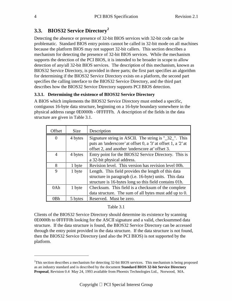
A BIOS which implements the BIOS32 Service Directory must embed a specific,contiguous 16-byte data structure, beginning on a 16-byte boundary somewhere in thephysical address range 0E0000h - 0FFFFFh. A description of the fields in the datastructure are given in Table 3.1.
Offset Size Description
0 4 bytes Signature string in ASCII. The string is "_32_". Thisputs an ’underscore’ at offset 0, a ’3’ at offset 1, a ’2’ atoffset 2, and another ’underscore at’ offset 3.
4 4 bytes Entry point for the BIOS32 Service Directory. This isa 32-bit physical address.
8 1 byte Revision level. This version has revision level 00h.9 1 byte Length. This field provides the length of this data
structure in paragraph (i.e. 16-byte) units. This datastructure is 16-bytes long so this field contains 01h.
0Ah 1 byte Checksum. This field is a checksum of the completedata structure. The sum of all bytes must add up to 0.
0Bh 5 bytes Reserved. Must be zero.
Table 3.1
Clients of the BIOS32 Service Directory should determine its existence by scanning0E0000h to 0FFFF0h looking for the ASCII signature and a valid, checksummed datastructure. If the data structure is found, the BIOS32 Service Directory can be accessedthrough the entry point provided in the data structure. If the data structure is not found,then the BIOS32 Service Directory (and also the PCI BIOS) is not supported by theplatform.
2This section describes a mechanism for detecting 32-bit BIOS services. This mechanism is being proposedas an industry standard and is described by the document Standard BIOS 32-bit Service DirectoryProposal, Revision 0.4 May 24, 1993 available from Phoenix Technologies Ltd., Norwood, MA.
Revision 2.1 PCI BIOS Specification 5
Copyright PCI Special Interest Group
3.3.2. Calling Interface for BIOS32 Service Directory
The BIOS32 Service Directory is accessed by doing a CALL FAR to the entry pointprovided in the Service data structure (see previous section). There are severalrequirements about the calling environment that must be met. The CS code segmentselector and the DS data segment selector must be set up to encompass the physical pageholding the entry point as well as the immediately following physical page. They mustalso have the same base. Platform BIOS writers must assume that CS is execute-only andDS is read-only. The SS stack segment selector must provide at least 1K of stack space.The calling environment must also allow access to IO space.
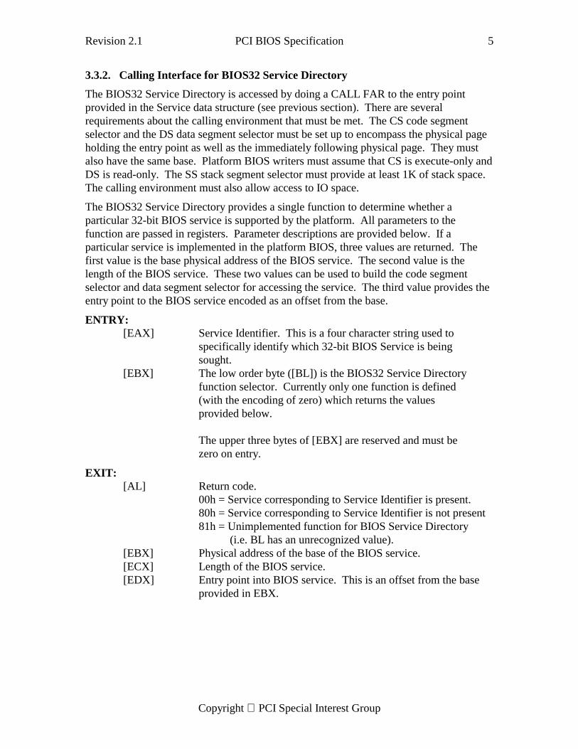
The BIOS32 Service Directory provides a single function to determine whether aparticular 32-bit BIOS service is supported by the platform. All parameters to thefunction are passed in registers. Parameter descriptions are provided below. If aparticular service is implemented in the platform BIOS, three values are returned. Thefirst value is the base physical address of the BIOS service. The second value is thelength of the BIOS service. These two values can be used to build the code segmentselector and data segment selector for accessing the service. The third value provides theentry point to the BIOS service encoded as an offset from the base.
ENTRY:[EAX] Service Identifier. This is a four character string used to
specifically identify which 32-bit BIOS Service is beingsought.
[EBX] The low order byte ([BL]) is the BIOS32 Service Directoryfunction selector. Currently only one function is defined(with the encoding of zero) which returns the valuesprovided below.
The upper three bytes of [EBX] are reserved and must bezero on entry.
EXIT:[AL] Return code.
00h = Service corresponding to Service Identifier is present.80h = Service corresponding to Service Identifier is not present81h = Unimplemented function for BIOS Service Directory (i.e. BL has an unrecognized value).
[EBX] Physical address of the base of the BIOS service.[ECX] Length of the BIOS service.[EDX] Entry point into BIOS service. This is an offset from the base
provided in EBX.
6 PCI BIOS Specification Revision 2.1
Copyright PCI Special Interest Group
3.4. PCI BIOS 32-bit service
The BIOS32 Service Directory may be used to detect the presence of the PCI BIOS. TheService Identifier for the PCI BIOS is "$PCI" (049435024h).
The 32-bit PCI BIOS functions must be accessed using CALL FAR. The CS and DSdescriptors must be setup to encompass the physical addresses specified by the Base andLength parameters returned by the BIOS32 Service Directory. The CS and DSdescriptors must have the same base. The calling environment must allow access to IOspace and provide at least 1K of stack space. Platform BIOS writers must assume that CSis execute-only and DS is read-only.
Revision 2.1 PCI BIOS Specification 7
Copyright PCI Special Interest Group
4. Host Interface
4.1. Identifying PCI Resources
The following group of functions allow the caller to determine first, if the PCI BIOSsupport is installed, and second, if specific PCI devices are present in the system.
4.1.1. PCI BIOS Present
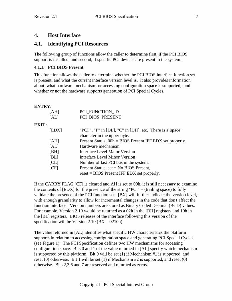
This function allows the caller to determine whether the PCI BIOS interface function setis present, and what the current interface version level is. It also provides informationabout what hardware mechanism for accessing configuration space is supported, andwhether or not the hardware supports generation of PCI Special Cycles.
ENTRY:[AH] PCI_FUNCTION_ID[AL] PCI_BIOS_PRESENT
EXIT:[EDX] "PCI ", "P" in [DL], "C" in [DH], etc. There is a ’space’
character in the upper byte.[AH] Present Status, 00h = BIOS Present IFF EDX set properly.[AL] Hardware mechanism[BH] Interface Level Major Version[BL] Interface Level Minor Version[CL] Number of last PCI bus in the system.[CF] Present Status, set = No BIOS Present,
reset = BIOS Present IFF EDX set properly.
If the CARRY FLAG [CF] is cleared and AH is set to 00h, it is still necessary to examinethe contents of [EDX] for the presence of the string "PCI" + (trailing space) to fullyvalidate the presence of the PCI function set. [BX] will further indicate the version level,with enough granularity to allow for incremental changes in the code that don’t affect thefunction interface. Version numbers are stored as Binary Coded Decimal (BCD) values.For example, Version 2.10 would be returned as a 02h in the [BH] registers and 10h inthe [BL] registers. BIOS releases of the interface following this version of thespecification will be Version 2.10 (BX = 0210h).
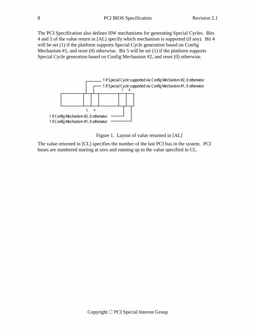
The value returned in [AL] identifies what specific HW characteristics the platformsupports in relation to accessing configuration space and generating PCI Special Cycles(see Figure 1). The PCI Specification defines two HW mechanisms for accessingconfiguration space. Bits 0 and 1 of the value returned in [AL] specify which mechanismis supported by this platform. Bit 0 will be set (1) if Mechanism #1 is supported, andreset (0) otherwise. Bit 1 will be set (1) if Mechanism #2 is supported, and reset (0)otherwise. Bits 2,3,6 and 7 are reserved and returned as zeros.
8 PCI BIOS Specification Revision 2.1
Copyright PCI Special Interest Group
The PCI Specification also defines HW mechanisms for generating Special Cycles. Bits4 and 5 of the value return in [AL] specify which mechanism is supported (if any). Bit 4will be set (1) if the platform supports Special Cycle generation based on ConfigMechanism #1, and reset (0) otherwise. Bit 5 will be set (1) if the platform supportsSpecial Cycle generation based on Config Mechanism #2, and reset (0) otherwise.
The value returned in [CL] specifies the number of the last PCI bus in the system. PCIbuses are numbered starting at zero and running up to the value specified in CL.
01
45
1 if Config Mechanism #1, 0 otherwise1 if Config Mechanism #2, 0 otherwise
1 if Special Cycle supported via Config Mechanism #1, 0 otherwise
1 if Special Cycle supported via Config Mechanism #2, 0 otherwise
Figure 1. Layout of value returned in [AL]
Revision 2.1 PCI BIOS Specification 9
Copyright PCI Special Interest Group
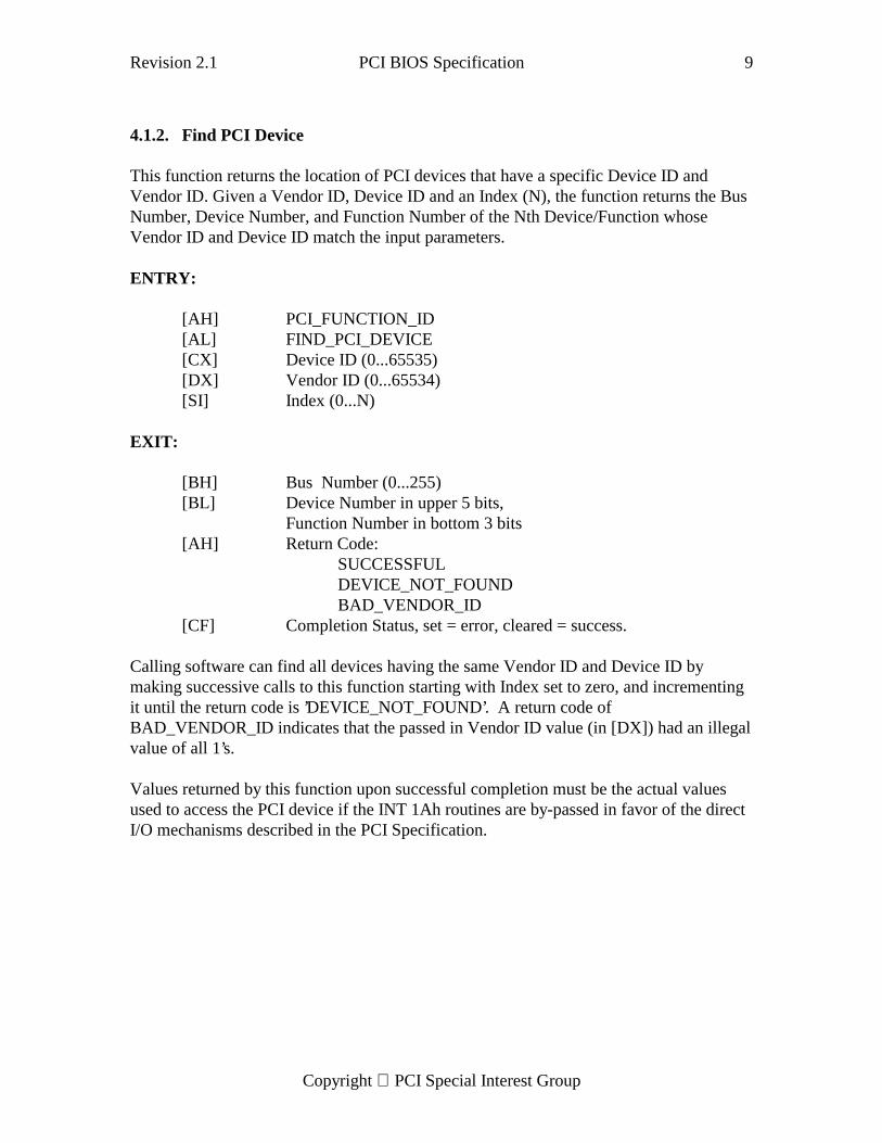
4.1.2. Find PCI Device
This function returns the location of PCI devices that have a specific Device ID andVendor ID. Given a Vendor ID, Device ID and an Index (N), the function returns the BusNumber, Device Number, and Function Number of the Nth Device/Function whoseVendor ID and Device ID match the input parameters.
ENTRY:
[AH] PCI_FUNCTION_ID[AL] FIND_PCI_DEVICE[CX] Device ID (0...65535)[DX] Vendor ID (0...65534)[SI] Index (0...N)
EXIT:
[BH] Bus Number (0...255)[BL] Device Number in upper 5 bits,
Function Number in bottom 3 bits[AH] Return Code:
SUCCESSFULDEVICE_NOT_FOUNDBAD_VENDOR_ID
[CF] Completion Status, set = error, cleared = success.
Calling software can find all devices having the same Vendor ID and Device ID bymaking successive calls to this function starting with Index set to zero, and incrementingit until the return code is ’DEVICE_NOT_FOUND’. A return code ofBAD_VENDOR_ID indicates that the passed in Vendor ID value (in [DX]) had an illegalvalue of all 1’s.
Values returned by this function upon successful completion must be the actual valuesused to access the PCI device if the INT 1Ah routines are by-passed in favor of the directI/O mechanisms described in the PCI Specification.
10 PCI BIOS Specification Revision 2.1
Copyright PCI Special Interest Group
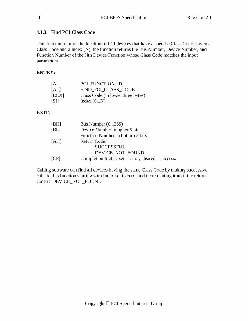
4.1.3. Find PCI Class Code
This function returns the location of PCI devices that have a specific Class Code. Given aClass Code and a Index (N), the function returns the Bus Number, Device Number, andFunction Number of the Nth Device/Function whose Class Code matches the inputparameters.
ENTRY:
[AH] PCI_FUNCTION_ID[AL] FIND_PCI_CLASS_CODE[ECX] Class Code (in lower three bytes)[SI] Index (0...N)
EXIT:
[BH] Bus Number (0...255)[BL] Device Number in upper 5 bits,
Function Number in bottom 3 bits[AH] Return Code:
SUCCESSFULDEVICE_NOT_FOUND
[CF] Completion Status, set = error, cleared = success.
Calling software can find all devices having the same Class Code by making successivecalls to this function starting with Index set to zero, and incrementing it until the returncode is ’DEVICE_NOT_FOUND’.
Revision 2.1 PCI BIOS Specification 11
Copyright PCI Special Interest Group
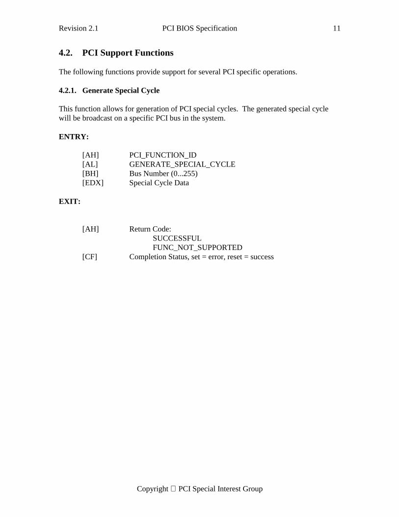
4.2. PCI Support Functions
The following functions provide support for several PCI specific operations.
4.2.1. Generate Special Cycle
This function allows for generation of PCI special cycles. The generated special cyclewill be broadcast on a specific PCI bus in the system.
ENTRY:
[AH] PCI_FUNCTION_ID[AL] GENERATE_SPECIAL_CYCLE[BH] Bus Number (0...255)[EDX] Special Cycle Data
EXIT:
[AH] Return Code:SUCCESSFULFUNC_NOT_SUPPORTED
[CF] Completion Status, set = error, reset = success
12 PCI BIOS Specification Revision 2.1
Copyright PCI Special Interest Group
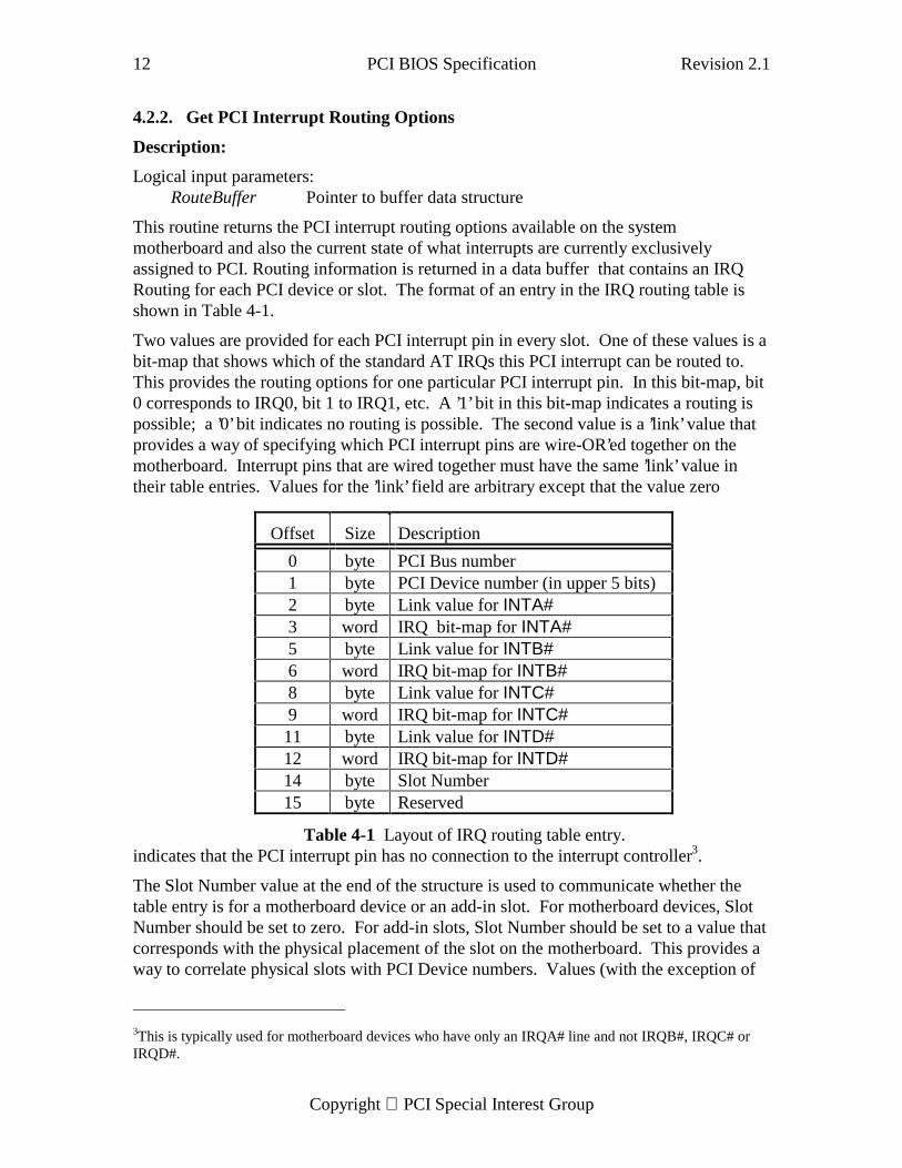
4.2.2. Get PCI Interrupt Routing Options
Description:
Logical input parameters:RouteBuffer Pointer to buffer data structure
This routine returns the PCI interrupt routing options available on the systemmotherboard and also the current state of what interrupts are currently exclusivelyassigned to PCI. Routing information is returned in a data buffer that contains an IRQRouting for each PCI device or slot. The format of an entry in the IRQ routing table isshown in Table 4-1.
Two values are provided for each PCI interrupt pin in every slot. One of these values is abit-map that shows which of the standard AT IRQs this PCI interrupt can be routed to.This provides the routing options for one particular PCI interrupt pin. In this bit-map, bit0 corresponds to IRQ0, bit 1 to IRQ1, etc. A ’1’ bit in this bit-map indicates a routing ispossible; a ’0’ bit indicates no routing is possible. The second value is a ’link’ value thatprovides a way of specifying which PCI interrupt pins are wire-OR’ed together on themotherboard. Interrupt pins that are wired together must have the same ’link’ value intheir table entries. Values for the ’link’ field are arbitrary except that the value zero
indicates that the PCI interrupt pin has no connection to the interrupt controller3.
The Slot Number value at the end of the structure is used to communicate whether thetable entry is for a motherboard device or an add-in slot. For motherboard devices, SlotNumber should be set to zero. For add-in slots, Slot Number should be set to a value thatcorresponds with the physical placement of the slot on the motherboard. This provides away to correlate physical slots with PCI Device numbers. Values (with the exception of
3This is typically used for motherboard devices who have only an IRQA# line and not IRQB#, IRQC# orIRQD#.
Offset Size Description
0 byte PCI Bus number1 byte PCI Device number (in upper 5 bits)2 byte Link value for INTA#3 word IRQ bit-map for INTA#5 byte Link value for INTB#6 word IRQ bit-map for INTB#8 byte Link value for INTC#9 word IRQ bit-map for INTC#11 byte Link value for INTD#12 word IRQ bit-map for INTD#14 byte Slot Number15 byte Reserved
Table 4-1 Layout of IRQ routing table entry.
Revision 2.1 PCI BIOS Specification 13
Copyright PCI Special Interest Group
00h) are OEM specific.4 For end user ease-of-use, slots in the system should be clearlylabeled (e.g. solder mask, back-panel, etc.).
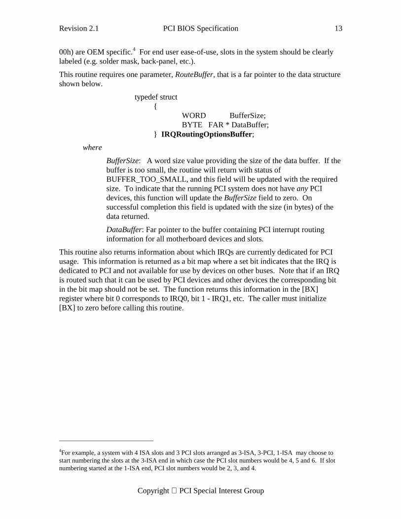
This routine requires one parameter, RouteBuffer, that is a far pointer to the data structureshown below.
typedef struct{
WORD BufferSize;BYTE FAR * DataBuffer;
} IRQRoutingOptionsBuffer;
where
BufferSize: A word size value providing the size of the data buffer. If thebuffer is too small, the routine will return with status ofBUFFER_TOO_SMALL, and this field will be updated with the requiredsize. To indicate that the running PCI system does not have any PCIdevices, this function will update the BufferSize field to zero. Onsuccessful completion this field is updated with the size (in bytes) of thedata returned.
DataBuffer: Far pointer to the buffer containing PCI interrupt routinginformation for all motherboard devices and slots.
This routine also returns information about which IRQs are currently dedicated for PCIusage. This information is returned as a bit map where a set bit indicates that the IRQ isdedicated to PCI and not available for use by devices on other buses. Note that if an IRQis routed such that it can be used by PCI devices and other devices the corresponding bitin the bit map should not be set. The function returns this information in the [BX]register where bit 0 corresponds to IRQ0, bit 1 - IRQ1, etc. The caller must initialize[BX] to zero before calling this routine.
4For example, a system with 4 ISA slots and 3 PCI slots arranged as 3-ISA, 3-PCI, 1-ISA may choose tostart numbering the slots at the 3-ISA end in which case the PCI slot numbers would be 4, 5 and 6. If slotnumbering started at the 1-ISA end, PCI slot numbers would be 2, 3, and 4.
14 PCI BIOS Specification Revision 2.1
Copyright PCI Special Interest Group
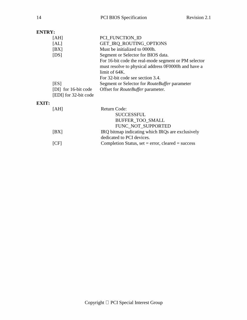
ENTRY:[AH] PCI_FUNCTION_ID[AL] GET_IRQ_ROUTING_OPTIONS[BX] Must be initialized to 0000h.[DS] Segment or Selector for BIOS data.
For 16-bit code the real-mode segment or PM selectormust resolve to physical address 0F0000h and have alimit of 64K.For 32-bit code see section 3.4.
[ES] Segment or Selector for RouteBuffer parameter[DI] for 16-bit code[EDI] for 32-bit code
Offset for RouteBuffer parameter.
EXIT:[AH] Return Code:
SUCCESSFULBUFFER_TOO_SMALLFUNC_NOT_SUPPORTED
[BX] IRQ bitmap indicating which IRQs are exclusivelydedicated to PCI devices.
[CF] Completion Status, set = error, cleared = success
Revision 2.1 PCI BIOS Specification 15
Copyright PCI Special Interest Group
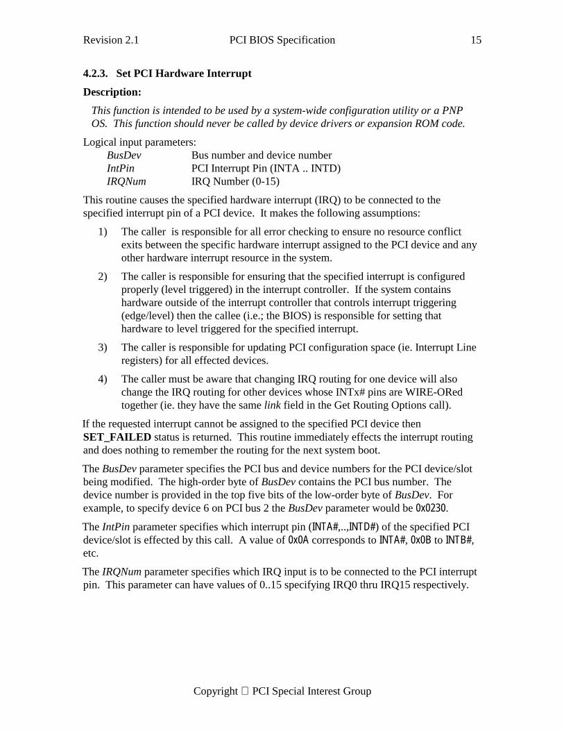
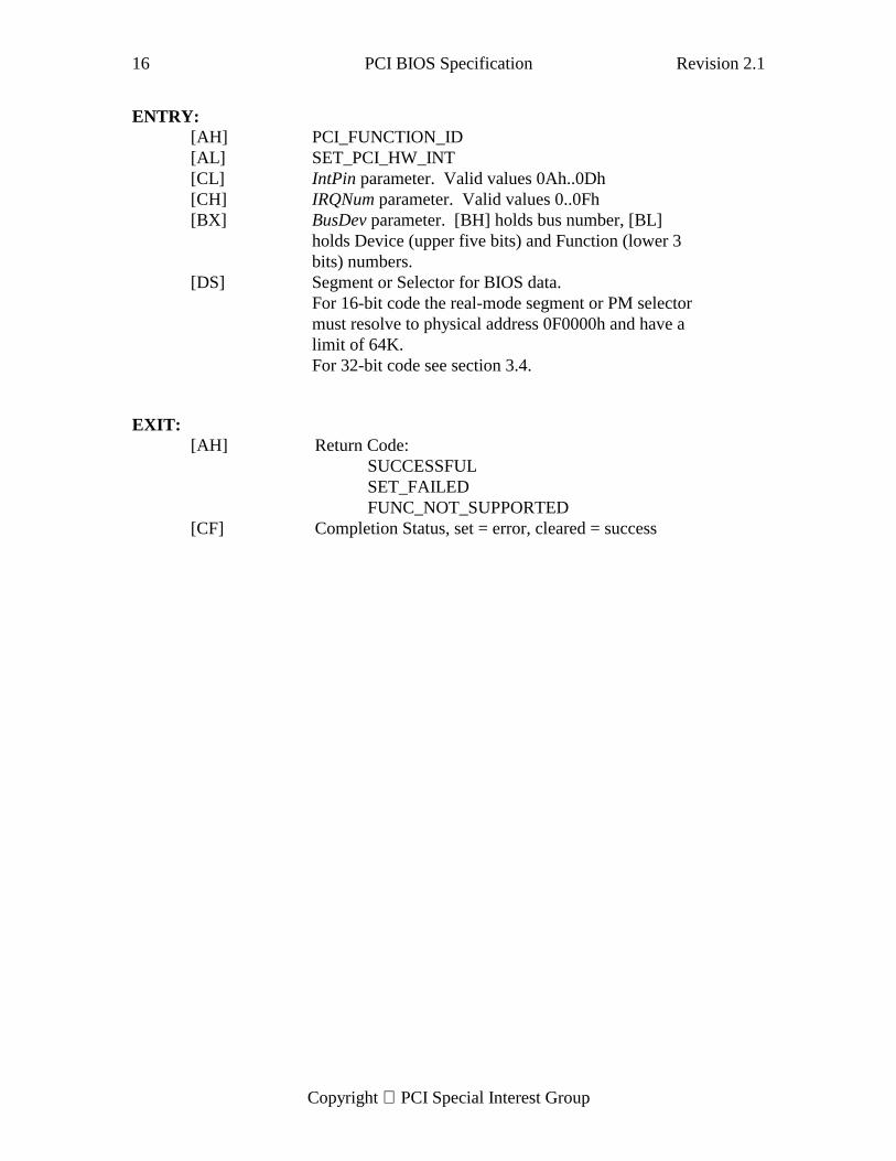
4.2.3. Set PCI Hardware Interrupt
Description:
This function is intended to be used by a system-wide configuration utility or a PNPOS. This function should never be called by device drivers or expansion ROM code.
Logical input parameters:BusDev Bus number and device numberIntPin PCI Interrupt Pin (INTA .. INTD)IRQNum IRQ Number (0-15)
This routine causes the specified hardware interrupt (IRQ) to be connected to thespecified interrupt pin of a PCI device. It makes the following assumptions:
1) The caller is responsible for all error checking to ensure no resource conflictexits between the specific hardware interrupt assigned to the PCI device and anyother hardware interrupt resource in the system.
2) The caller is responsible for ensuring that the specified interrupt is configuredproperly (level triggered) in the interrupt controller. If the system containshardware outside of the interrupt controller that controls interrupt triggering(edge/level) then the callee (i.e.; the BIOS) is responsible for setting thathardware to level triggered for the specified interrupt.
3) The caller is responsible for updating PCI configuration space (ie. Interrupt Lineregisters) for all effected devices.
4) The caller must be aware that changing IRQ routing for one device will alsochange the IRQ routing for other devices whose INTx# pins are WIRE-ORedtogether (ie. they have the same link field in the Get Routing Options call).
If the requested interrupt cannot be assigned to the specified PCI device thenSET_FAILED status is returned. This routine immediately effects the interrupt routingand does nothing to remember the routing for the next system boot.
The BusDev parameter specifies the PCI bus and device numbers for the PCI device/slotbeing modified. The high-order byte of BusDev contains the PCI bus number. Thedevice number is provided in the top five bits of the low-order byte of BusDev. Forexample, to specify device 6 on PCI bus 2 the BusDev parameter would be 0x0230.
The IntPin parameter specifies which interrupt pin (INTA#,..,INTD#) of the specified PCIdevice/slot is effected by this call. A value of 0x0A corresponds to INTA#, 0x0B to INTB#,etc.
The IRQNum parameter specifies which IRQ input is to be connected to the PCI interruptpin. This parameter can have values of 0..15 specifying IRQ0 thru IRQ15 respectively.
16 PCI BIOS Specification Revision 2.1
Copyright PCI Special Interest Group
ENTRY:[AH] PCI_FUNCTION_ID[AL] SET_PCI_HW_INT[CL] IntPin parameter. Valid values 0Ah..0Dh[CH] IRQNum parameter. Valid values 0..0Fh[BX] BusDev parameter. [BH] holds bus number, [BL]
holds Device (upper five bits) and Function (lower 3bits) numbers.
[DS] Segment or Selector for BIOS data.For 16-bit code the real-mode segment or PM selectormust resolve to physical address 0F0000h and have alimit of 64K.For 32-bit code see section 3.4.
EXIT:[AH] Return Code:
SUCCESSFULSET_FAILEDFUNC_NOT_SUPPORTED
[CF] Completion Status, set = error, cleared = success
Revision 2.1 PCI BIOS Specification 17
Copyright PCI Special Interest Group
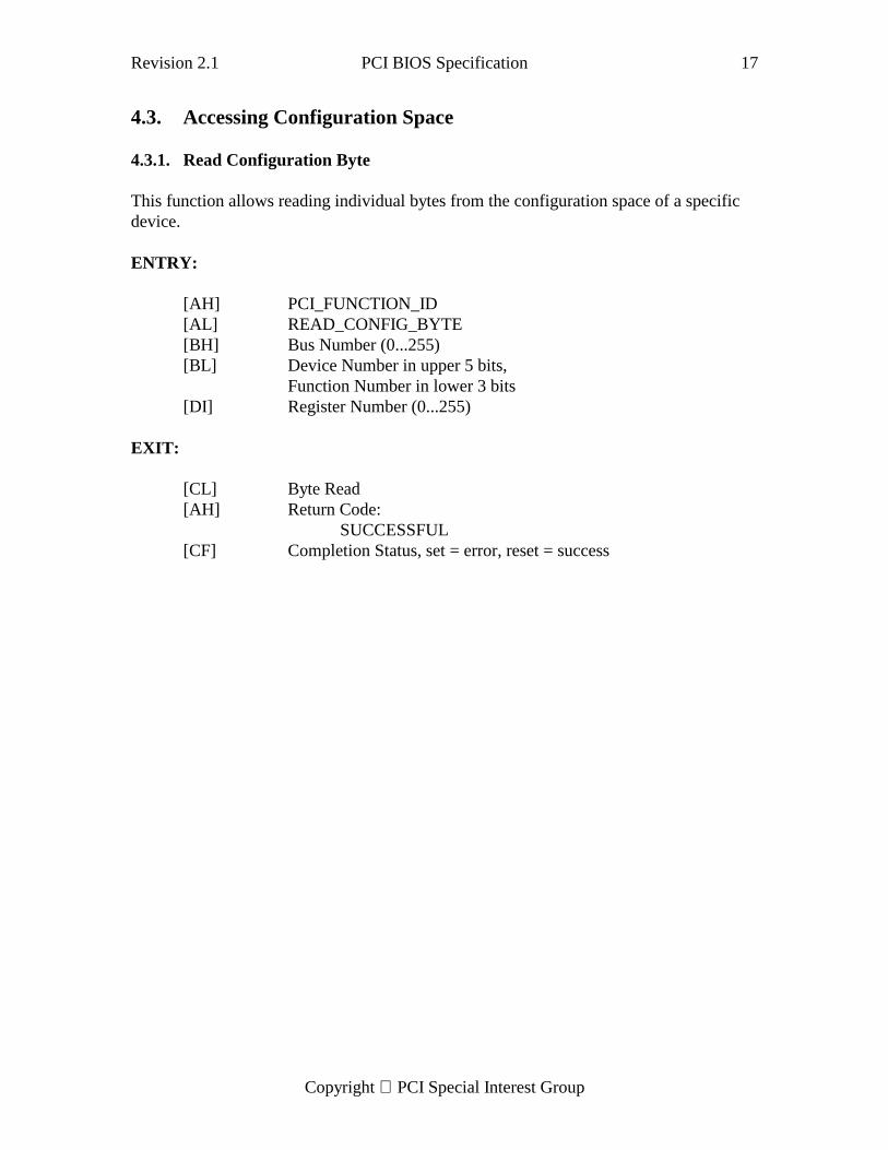
4.3. Accessing Configuration Space
4.3.1. Read Configuration Byte
This function allows reading individual bytes from the configuration space of a specificdevice.
ENTRY:
[AH] PCI_FUNCTION_ID[AL] READ_CONFIG_BYTE[BH] Bus Number (0...255)[BL] Device Number in upper 5 bits,
Function Number in lower 3 bits[DI] Register Number (0...255)
EXIT:
[CL] Byte Read[AH] Return Code:
SUCCESSFUL[CF] Completion Status, set = error, reset = success
18 PCI BIOS Specification Revision 2.1
Copyright PCI Special Interest Group
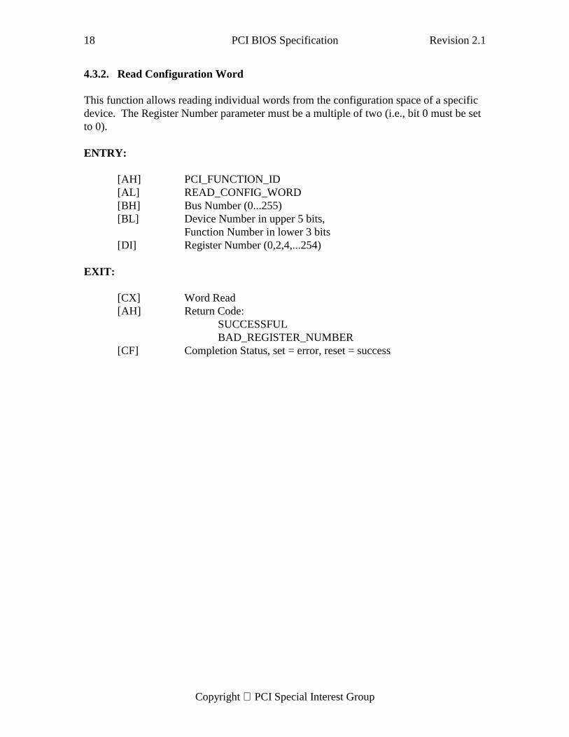
4.3.2. Read Configuration Word
This function allows reading individual words from the configuration space of a specificdevice. The Register Number parameter must be a multiple of two (i.e., bit 0 must be setto 0).
ENTRY:
[AH] PCI_FUNCTION_ID[AL] READ_CONFIG_WORD[BH] Bus Number (0...255)[BL] Device Number in upper 5 bits,
Function Number in lower 3 bits[DI] Register Number (0,2,4,...254)
EXIT:
[CX] Word Read[AH] Return Code:
SUCCESSFULBAD_REGISTER_NUMBER
[CF] Completion Status, set = error, reset = success
Revision 2.1 PCI BIOS Specification 19
Copyright PCI Special Interest Group
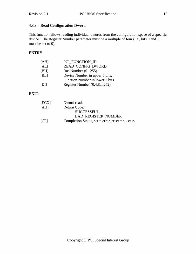
4.3.3. Read Configuration Dword
This function allows reading individual dwords from the configuration space of a specificdevice. The Register Number parameter must be a multiple of four (i.e., bits 0 and 1must be set to 0).
ENTRY:
[AH] PCI_FUNCTION_ID[AL] READ_CONFIG_DWORD[BH] Bus Number (0...255)[BL] Device Number in upper 5 bits,
Function Number in lower 3 bits[DI] Register Number (0,4,8,...252)
EXIT:
[ECX] Dword read.[AH] Return Code:
SUCCESSFULBAD_REGISTER_NUMBER
[CF] Completion Status, set = error, reset = success
20 PCI BIOS Specification Revision 2.1
Copyright PCI Special Interest Group
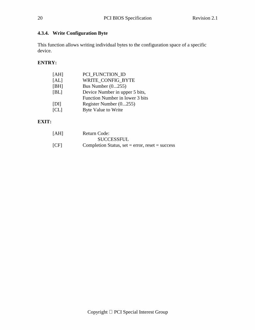
4.3.4. Write Configuration Byte
This function allows writing individual bytes to the configuration space of a specificdevice.
ENTRY:
[AH] PCI_FUNCTION_ID[AL] WRITE_CONFIG_BYTE[BH] Bus Number (0...255)[BL] Device Number in upper 5 bits,
Function Number in lower 3 bits[DI] Register Number (0...255)[CL] Byte Value to Write
EXIT:
[AH] Return Code:SUCCESSFUL
[CF] Completion Status, set = error, reset = success
Revision 2.1 PCI BIOS Specification 21
Copyright PCI Special Interest Group
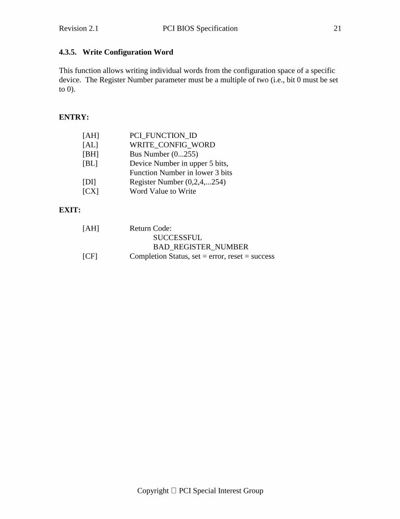
4.3.5. Write Configuration Word
This function allows writing individual words from the configuration space of a specificdevice. The Register Number parameter must be a multiple of two (i.e., bit 0 must be setto 0).
ENTRY:
[AH] PCI_FUNCTION_ID[AL] WRITE_CONFIG_WORD[BH] Bus Number (0...255)[BL] Device Number in upper 5 bits,
Function Number in lower 3 bits[DI] Register Number (0,2,4,...254)[CX] Word Value to Write
EXIT:
[AH] Return Code:SUCCESSFULBAD_REGISTER_NUMBER
[CF] Completion Status, set = error, reset = success
22 PCI BIOS Specification Revision 2.1
Copyright PCI Special Interest Group
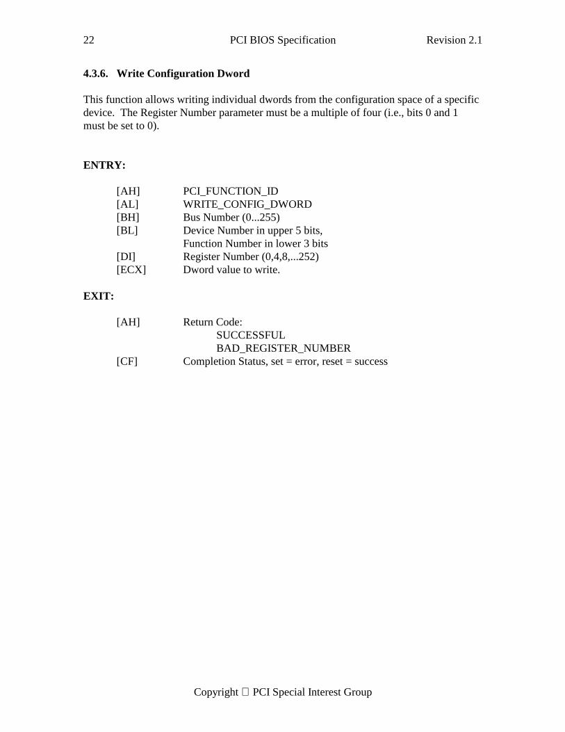
4.3.6. Write Configuration Dword
This function allows writing individual dwords from the configuration space of a specificdevice. The Register Number parameter must be a multiple of four (i.e., bits 0 and 1must be set to 0).
ENTRY:
[AH] PCI_FUNCTION_ID[AL] WRITE_CONFIG_DWORD[BH] Bus Number (0...255)[BL] Device Number in upper 5 bits,
Function Number in lower 3 bits[DI] Register Number (0,4,8,...252)[ECX] Dword value to write.
EXIT:
[AH] Return Code:SUCCESSFULBAD_REGISTER_NUMBER
[CF] Completion Status, set = error, reset = success
Revision 2.1 PCI BIOS Specification 23
Copyright PCI Special Interest Group
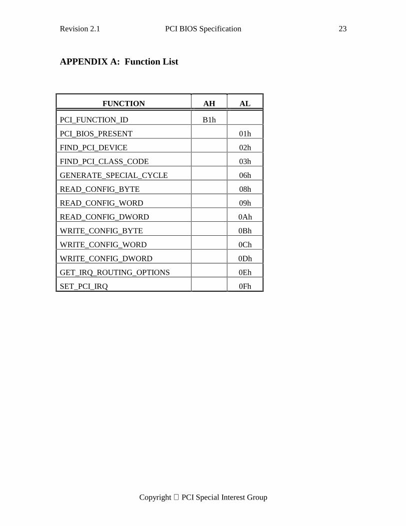
APPENDIX A: Function List
FUNCTION AH AL
PCI_FUNCTION_ID B1h
PCI_BIOS_PRESENT 01h
FIND_PCI_DEVICE 02h
FIND_PCI_CLASS_CODE 03h
GENERATE_SPECIAL_CYCLE 06h
READ_CONFIG_BYTE 08h
READ_CONFIG_WORD 09h
READ_CONFIG_DWORD 0Ah
WRITE_CONFIG_BYTE 0Bh
WRITE_CONFIG_WORD 0Ch
WRITE_CONFIG_DWORD 0Dh
GET_IRQ_ROUTING_OPTIONS 0Eh
SET_PCI_IRQ 0Fh
24 PCI BIOS Specification Revision 2.1
Copyright PCI Special Interest Group
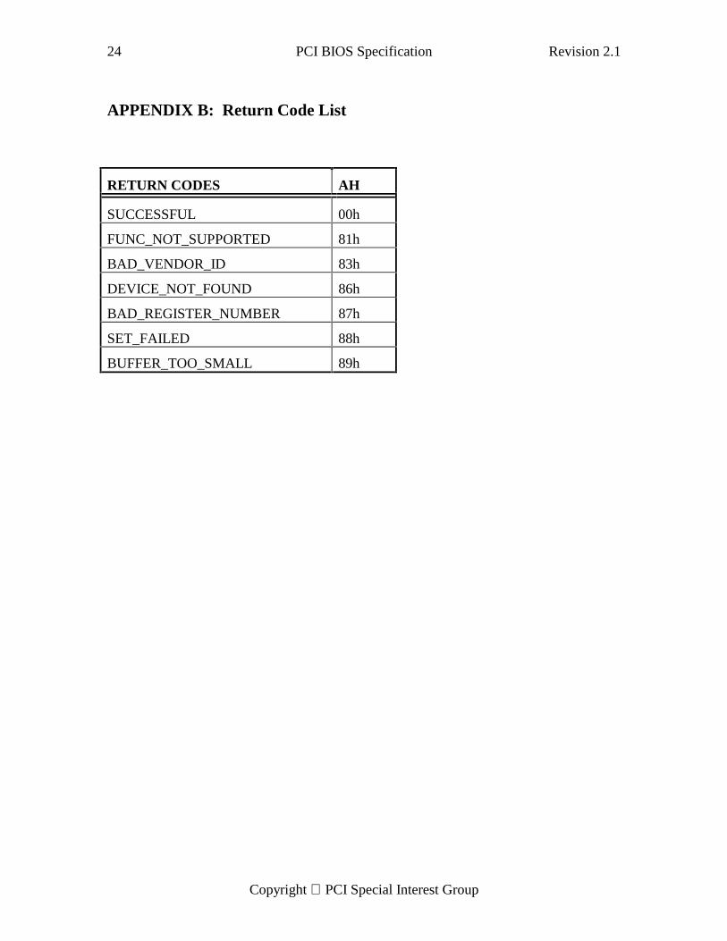
APPENDIX B: Return Code List
RETURN CODES AH
SUCCESSFUL 00h
FUNC_NOT_SUPPORTED 81h
BAD_VENDOR_ID 83h
DEVICE_NOT_FOUND 86h
BAD_REGISTER_NUMBER 87h
SET_FAILED 88h
BUFFER_TOO_SMALL 89h