Part VIII: Requirements and Test Methods for Digital ... VIII: Requirements and Test Methods for...
70
Aussi disponible en français – SC-03 Partie VIII CS-03 Part VIII Issue 9, Amendment 5 March 2016 Spectrum Management and Telecommunications Compliance Specification for Terminal Equipment, Terminal Systems, Network Protection Devices, Connection Arrangements and Hearing Aids Compatibility Part VIII: Requirements and Test Methods for Digital Subscriber Line (xDSL) Terminal Equipment
Transcript of Part VIII: Requirements and Test Methods for Digital ... VIII: Requirements and Test Methods for...

Aussi disponible en français – SC-03 Partie VIII
CS-03 Part VIII
Issue 9, Amendment 5 March 2016
Spectrum Management and Telecommunications
Compliance Specification for Terminal Equipment, Terminal Systems, Network Protection Devices, Connection Arrangements and Hearing Aids Compatibility
Part VIII: Requirements and Test Methods for Digital Subscriber Line (xDSL) Terminal Equipment

Part VIII: Requirements and Test Methods for Digital Subscriber Line (xDSL) Terminal Equipment CS-03 Part VIII
i
Contents
1. Introduction ........................................................................................................................1
1.1 Scope ........................................................................................................................1 1.2 Technical Requirements...........................................................................................4 1.3 Sequence of Equipment Testing ..............................................................................5 1.4 Connecting Arrangements .......................................................................................6 1.5 Operational Check ...................................................................................................6
2. Electrical and Mechanical Stresses ..................................................................................6
3. Network Protection Requirements and Test Methods ...................................................6 3.1 Laboratory Environment ..........................................................................................7 3.2 Transmitted Spectral Response ................................................................................7 3.3 Total Signal Power .................................................................................................52 3.4 Transverse Balance ................................................................................................55 3.5 Longitudinal Output Voltage .................................................................................59
Annex A — Deployment Guidelines ...........................................................................................64
Annex B — Informative References ...........................................................................................68

Part VIII: Requirements and Test Methods for Digital Subscriber Line (xDSL) Terminal Equipment CS-03 Part VIII
1
1. Introduction 1.1 Scope This part sets forth the minimum network protection requirements for:
• asymmetrical digital subscriber line (ADSL) terminal equipment (TE) using either carrierless amplitude/phase (CAP) modulation or discrete multi-tone (DMT) technology;
• asymmetrical digital subscriber line 2 (ADSL2) transceivers; • asymmetrical digital subscriber line 2 plus (ADSL2+) transceivers with extended
bandwidth; • reach extended asymmetrical digital subscriber line (READSL) transceivers; • high bit rate digital subscriber line 2 (HDSL2) TE using trellis coded pulse amplitude
modulation (TC-PAM); • symmetrical digital subscriber line (SDSL) TE using two binary one quaternary line code
(2B1Q); • single pair high-speed digital subscriber line (SHDSL) TE using TC-PAM; • 4-wire high bit rate digital subscriber line 2 (HDSL4) TE using TC-PAM; • very high bit rate digital subscriber line (VDSL) TE using either a single-carrier
modulation (QAM) or a multi-carrier modulation (DMT); and • very high bit rate digital subscriber line 2 (VDSL2) TE using DMT modulation.
ADSL equipment uses one cable pair where transmission of voice band signals and data can occur simultaneously. Asymmetric transmission of data provides a high bit rate downstream (towards the subscriber) and a lower bit rate upstream (towards the central office). Refer to Figure 1.1(a) for the ADSL functional reference model.
ADSL2 equipment uses one cable pair and allows high-speed data transmission between the network operator end (ATU-C) and the customer end (ATU-R). Refer to Figure 1.1(a) for the ADSL2 functional reference model.
HDSL2 is a second generation HDSL loop transmission system that is standardized. The system is designed to transport a 1.544 Mbps payload on a single non-loaded twisted pair at carrier serving area distances. Refer to Figure 1.1(b) for the HDSL2 functional reference model.
2B1Q SDSL has the same symbol rate, baud rate and power spectral density at both the network operator end (STU-C) and the customer end (STU-R). A 2B1Q SDSL system may vary its data rate from 64 kbps to 2320 kbps. Refer to Figure 1.1(b) for the 2B1Q SDSL functional reference model. Typically, 2B1Q SDSL equipment transmits a symmetric signal on a single copper pair.
SHDSL uses TC-PAM on a single copper pair to transmit a symmetric signal with data rates from 192 kbps to 2.312 Mbps. Refer to Figure 1.1(b) for the SHDSL functional reference model.
HDSL4 is a variant of SHDSL, using TC-PAM on two copper pairs (four wires) to transmit an asymmetric signal with a data rate of 768/776 kbps. Refer to Figure 1.1(b) for the HDSL4 functional reference model.

Part VIII: Requirements and Test Methods for Digital Subscriber Line (xDSL) Terminal Equipment CS-03 Part VIII
2
VDSL is a DSL technology designed to support very high-speed data transmission over relatively short twisted-pair loops, which simultaneously support plain old telephone service (POTS). The system supports both symmetric and asymmetric data transmission with payload rates as described in Table 1.1.
VDSL2 is an enhancement to VDSL that supports asymmetric and symmetric transmission at a bidirectional net data rate up to 200 Mbit/s on twisted pairs using a bandwidth of up to 30 MHz.
Table 1.1: VDSL Service Types and Data Rates
Service Type Downstream Data Rate (Mbps)
Upstream Data Rate (Mbps)
Asymmetric 22 3 Symmetric
6 6
13 13
Note: Table 1.1 represents the minimum payload rates for VDSL transmission. The actual equipment may support other rates.
The term xDSL is used in this document to refer generically to any of the digital subscriber line variants.

Part VIII: Requirements and Test Methods for Digital Subscriber Line (xDSL) Terminal Equipment CS-03 Part VIII
3
Figure 1.1(a): TE Functional Reference Model for ADSL, ADSL2, ADSL2+, READSL, VDSL and VDSL2
Notes: TU-C = ADSL/ADSL2/ADSL2+/READSL/VDSL/VDSL2 transceiver unit, central office end TU-R = ADSL/ADSL2/ADSL2+/READSL/VDSL/VDSL2 transceiver unit, remote terminal end PSTN = public switched telephone network POTS = plain old telephone service
OTHER DIGITAL
NETWORK DATA TERMINAL
TU-C T.E.
TU-R T.E.
METALLIC CHANNEL
U-C U-R
POTS SPLITTER
POTS SPLITTER
TELEPHONE SET
PSTN

Part VIII: Requirements and Test Methods for Digital Subscriber Line (xDSL) Terminal Equipment CS-03 Part VIII
4
Figure 1.1(b): TE Functional Reference Model for HDSL2, SDSL, SHDSL and HDSL4
Note: TU-C = HDSL2/SDSL/SHDSL/HDSL4 transceiver unit, central office end
TU-R = HDSL2/SDSL/SHDSL/HDSL4 transceiver unit, remote terminal end
1.2 Technical Requirements
Any xDSL terminal equipment connected to the U-R interface shall comply with the technical requirements detailed in tables 1.2(a) and 1.2(b).
Table 1.2(a): Technical Requirements (CS-03, Issue 9, Part I)
Section Technical Requirements HDSL2/ SDSL/ SHDSL/HDSL4
ADSL/ADSL2/ADSL2+/ READSL/VDSL/VDSL2
2.1 Mechanical Shock * *
2.2 Dielectric Strength * *
2.3.1 Hazardous Voltage Limitations Requirements
* *
DIGITAL NETWORK DATA
TERMINAL
TU-C
T.E. TU-R T.E.
METALLIC CHANNEL
U-C U-R

Part VIII: Requirements and Test Methods for Digital Subscriber Line (xDSL) Terminal Equipment CS-03 Part VIII
5
Section Technical Requirements HDSL2/ SDSL/ SHDSL/HDSL4
ADSL/ADSL2/ADSL2+/ READSL/VDSL/VDSL2
2.3.7 Connection of Non-registered Equipment to Registered TE or Registered Protective Circuitry
* *
2.3.10 Hazards Due to Intentional Paths to Ground
* *
2.4.1 Telephone Line Surge - Type A * *
2.4.2 Telephone Line Surge - Type B * *
2.5.1 Power Line Surge *
3.3.2.1 Longitudinal AC Signals (0.1 -4 KHz)
*
3.3.2.2 Longitudinal AC Signals (4- 12 KHz)
*
3.6 Transverse Balance * 3.7.1 Metallic and Longitudinal DC
Resistance (Loop-start Interface) *
3.7.2 DC Current during Ringing (Loop-start and Ground-start Interface)
*
3.7.3 Metallic and Longitudinal Impedance during Ringing (Loop-start and Ground-start Interfaces)
*
Note: The asterisk (*) indicates that the TE must comply with the listed technical requirements.
Table 1.2(b): Technical Requirements (CS-03, Issue 9, Part VIII)
Section Technical Requirements 3.2 Transmitted Spectral Response 3.3 Total Signal Power 3.4 Transverse Balance 3.5 Longitudinal Output Voltage
1.3 Sequence of Equipment Testing
The tests related to the technical requirements listed in Section 1.2 shall be performed in the following order:

Part VIII: Requirements and Test Methods for Digital Subscriber Line (xDSL) Terminal Equipment CS-03 Part VIII
6
1. Part VIII, Section 1.4 Connecting Arrangements 2. Part VIII, Section 1.5 Operational Check 3. Part I, Section 2.2 Dielectric Strength 4. Part I, Section 2.3 Hazardous Voltage Limitations (as applicable) 5. Part I, Section 3. Network Protection Requirements and Tests 6. Part VIII, Section 3. Network Protection Requirements and Test Methods 7. Part I, Section 2.1 Mechanical Shock 8. Part I, Section 2.4.2 Surge Voltage - Type B 9. Part I, Section 1.5 Operational Check 10. Part I, Section 2.2 Dielectric Strength 11. Part I, Section 3. Network Protection Requirements and Tests 12. Part VIII, Section 3. Network Protection Requirements and Test Methods 13. Part I, Section 2.3 Hazardous Voltage Limitations (as applicable) 14. Part I, Section 2.4.1 Surge Voltage - Type A 15. Part I, Section 2.5 Power Line Surge 16. Part I, Section 1.5 Operational Check 17. Part I, Section 2.2 Dielectric Strength 18. Part I, Section 3. Network Protection Requirements and Tests 19. Part VIII, Section 3. Network Protection Requirements and Test Methods 20. Part I, Section 2.3 Hazardous Voltage Limitations (as applicable)
1.4 Connecting Arrangements
Cords and plugs of xDSL TE intended for direct electrical connection to the public switched telephone network shall comply with CS-03, Part III, Acceptable Methods of Connection for Single Line and Multi-Line Terminal Equipment.
1.5 Operational Check
When the operational checks are performed before the application of electrical stress, the TE shall be fully operational, in accordance with the manufacturer’s operating instructions, for those features necessary to allow demonstration of compliance with all applicable requirements of Part I, Section 3. When the operational checks are repeated after the electrical stress of Part I, Section 2, it is permissible that the TE be partially or fully inoperable. 2. Electrical and Mechanical Stresses The technical requirements and methods of application for electrical and mechanical stresses are given in Part I, Section 2. 3. Network Protection Requirements and Test Methods Applicable network protection requirements of Section 3 of Part I must be met for any terminal equipment under the scope of this document. The technical requirements for xDSL terminal equipment are specified in Table 1.2(a).

Part VIII: Requirements and Test Methods for Digital Subscriber Line (xDSL) Terminal Equipment CS-03 Part VIII
7
3.1 Laboratory Environment
All tests used to determine compliance of TE with these requirements shall be conducted in a laboratory environment at normal room temperature and humidity. 3.2 Transmitted Spectral Response
3.2.1 Requirements
3.2.1.1 Power Spectral Density at the U-R Interface for ADSL
The power spectral density (PSD) of the signal transmitted over the ADSL upstream channel (ATU-R output) shall not exceed the PSD mask in Figure 3.2.1.1. The numerical values for the mask are provided in Table 3.2.1.1.
Table 3.2.1.1: ATU-R PSD Mask Definition for ADSL
Frequency Band (kHz)
PSD (dBm/Hz) Across 100 Ω
0.2 < ƒ ≤ 4 -97.5
4 < ƒ ≤ 25.875 -92.5 + 21.5 x log2(ƒ/4)
25.875 < ƒ ≤ 138 -34.5
138 <ƒ≤ 307 -34.5 - 48 x log2(ƒ/138)
307 <IJ 1221 -90
1221 <ƒ≤ 1630 -90 peak, with max power in the [ƒ, ƒ+ 1 MHz] window of (-90 - 48 x log2(ƒ/1221) + 60) dBm
1630 <ƒ≤ 30000 -90 peak, with max power in the [ƒ, ƒ+ 1 MHz] window of -50 dBm
Note 1: The breakpoint frequencies and PSD values are exact. Note 2: Above 25.875 kHz, the peak PSD shall be measured with a 10 kHz resolution bandwidth.
Below 25.875 kHz, the peak PSD shall be measured with a 100 Hz resolution bandwidth. Note 3: The power in a 1 MHz sliding window is measured in a 1 MHz bandwidth, starting at
the measurement frequency.

Part VIII: Requirements and Test Methods for Digital Subscriber Line (xDSL) Terminal Equipment CS-03 Part VIII
8
Figure 3.2.1.1: ATU-R Upstream Transmission PSD Mask for ADSL
3.2.1.2 Power Spectral Density at the U-R Interface for ADSL2
Table 3.2.1.2: ATU-R PSD Mask Definition for ADSL2
Frequency Band (kHz) PSD (dBm/Hz) Across 100 Ω
0.2 < ƒ ≤ 1.5 -46.5
1.5 < ƒ ≤ 3 -34.5 + 12 x log2(ƒ/3)
3 < ƒ ≤ 138 -34.5
138 < ƒ ≤ 307 -34.5 - 48 x log2(ƒ/138)
307 < ƒ ≤ 1221 -90 peak, with max power in the [ƒ , ƒ+ 100 kHz] window of -42.5 dBm
1221 < ƒ ≤ 1630 -90 peak, with max power in the [ƒ , ƒ+ 1 MHz] window of (-90 - 48 x log2(ƒ/1221) + 60) dBm
1630 < ƒ ≤ 30000 -90 peak, with max power in the [ƒ, ƒ+ 1 MHz] window of -50 dBm

Part VIII: Requirements and Test Methods for Digital Subscriber Line (xDSL) Terminal Equipment CS-03 Part VIII
9
Note 1: The breakpoint frequencies and PSD values are exact. Note 2: Above 3 kHz, the peak PSD shall be measured with a 10 kHz resolution bandwidth.
Below 3 kHz, the peak PSD shall be measured with a 100 Hz resolution bandwidth. Note 3: The power in a 1 MHz sliding window is measured in a 1 MHz bandwidth, starting at the measurement frequency.
Figure 3.2.1.2: ATU-R Upstream Transmission PSD Mask for ADSL2 All-Digital Mode
Frequency (kHz)
3.2.1.3 Power Spectral Density at the U-R Interface for ADSL2 All-Digital Mode Spectral Compatibility with ISDN
Table 3.2.1.3(a): ATU-R PSD Mask Definition for ADSL2
Frequency Band (kHz) PSD (dBm/Hz) Across 100 Ω

Part VIII: Requirements and Test Methods for Digital Subscriber Line (xDSL) Terminal Equipment CS-03 Part VIII
10
0.2 < ƒ ≤ 1.5 -46.5
1.5 < ƒ ≤ 3 -46.5 + (inband peak PSD + 46.5) x log2(f/1.5)
3 < ƒ ≤ f1 inband peak PSD
f1 < ƒ ≤ f2 inband peak PSD - 48 log2(f/f1)
f2 < ƒ ≤ 1221 -90
1221 < ƒ ≤ 1630 -90 peak, with max power in the [f,ƒ+ 1 MHz] window of (-30 - 48 x log2(f/1221)) dBm
1630 < ƒ ≤ 30000 -90 peak, with max power in the [f,ƒ+ 1 MHz] window of -50 dBm
Note 1: The breakpoint frequencies and PSD values are exact. Note 2: Above 3 kHz, the peak PSD shall be measured with a 10 kHz resolution bandwidth. Note 3: The power in a 1 MHz sliding window is measured in a 1 MHz bandwidth, starting at the
measurement frequency.
Table 3.2.1.3(b): ATU-R Inband Peak PSD Mask Designator for ADSL2
Designator Inband Peak PSD (dBm/Hz)
Frequency f1 (kHz)
Frequency f2 (kHz)
ADLU - 32 -34.5 138 307
ADLU - 36 -35 155.25 343
ADLU - 40 -35.5 172.5 379
ADLU - 44 -35.9 189.75 415
ADLU - 48 -36.3 207 450
ADLU - 52 -36.6 224.25 485
ADLU - 56 -36.9 241.5 520
ADLU - 60 -37.2 258.75 554
ADLU - 64 -37.5 276 589

Part VIII: Requirements and Test Methods for Digital Subscriber Line (xDSL) Terminal Equipment CS-03 Part VIII
11
Figure 3.2.1.3(a): ATU-R Upstream Transmission PSD Mask for ADSL2 All-Digital Mode

Part VIII: Requirements and Test Methods for Digital Subscriber Line (xDSL) Terminal Equipment CS-03 Part VIII
12
Figure 3.2.1.3(b): ATU-R Upstream Transmission PSD Mask for ADSL2 All-Digital Mode
3.2.1.4 Power Spectral Density at the U-R Interface for ADSL2 READSL
The PSD of the signal transmitted over the ADSL2 READSL upstream channel (ATU-R output) shall comply with either of the following PSD masks: Mask 1 given in Figure 3.2.1.4(a) or Mask 2 given in Figure 3.2.1.4(b). Table 3.2.1.4(a) provides the numerical values for Mask 1, and Table 3.2.1.4(b) provides the numerical values for Mask 2.
Table 3.2.1.4(a): ATU-R PSD Mask 1 Definition
Frequency Band (kHz)
PSD (dBm/Hz) Across 100 Ω
0.2 < ƒ ≤ 4 -97.5, with max power in the 0-4 kHz band of +15 dBm
4 < ƒ ≤ 25.875 -92.5 + 22.13 x log2(f/4)
25.875 < ƒ ≤ 103.5 -32.9
103.5 < ƒ ≤ 686 Max -32.9 - 72 x log2 (f/103.5), 10 x log10[0.05683 x (fx103)-1.5]
686 < ƒ ≤ 1411 -100
1411 < ƒ ≤ 1630 -100 peak, with max power in the [f,ƒ+ 1 MHz] window of (-110 - 48 x log2(f/1411) + 60) dBm
1630 < ƒ ≤ 5275 -100 peak, with max power in the [f,ƒ+ 1 MHz] window of (-110 - 1.18 x log2(f/1630) + 60) dBm

Part VIII: Requirements and Test Methods for Digital Subscriber Line (xDSL) Terminal Equipment CS-03 Part VIII
13
5275 < ƒ ≤ 30000 -100 peak, with max power in the [f,ƒ+ 1 MHz] window of -52 dBm
Table 3.2.1.4(b): ATU-R PSD Mask 2 Definition
Frequency Band (kHz)
PSD (dBm/Hz) Across 100 Ω
0.2 < ƒ ≤ 4 -97.5, with max power in the 0-4 kHz band of +15 dBm
4 < ƒ ≤ 25.875 -92.5 + 23.43 x log2(f/4)
25.875 < ƒ ≤ 60.375 -29.4
60.375 < ƒ ≤ 686 Max -29.4 - 72 x log2 (f/60.375), 10 x log10[0.05683 x (fx103)-1.5]
686 < ƒ ≤ 1411 -100
1411 < ƒ ≤ 1630 -100 peak, with max power in the [f,ƒ+ 1 MHz] window of (-110 - 48 x log2(f/1411) + 60) dBm
1630 < ƒ ≤ 5275 -100 peak, with max power in the [f,ƒ+ 1 MHz] window of (-110 - 1.18 x log2(f/1630) + 60) dBm
5275 < ƒ ≤ 30000 -100 peak, with max power in the [f,ƒ+ 1 MHz] window of -52 dBm

Part VIII: Requirements and Test Methods for Digital Subscriber Line (xDSL) Terminal Equipment CS-03 Part VIII
14
Figure 3.2.1.4(a): ATU-R Upstream Transmission PSD Mask 1 for ADSL2 READSL
Note 1: The breakpoint frequencies and PSD values are exact. Note 2: Above 25.875 kHz, the peak PSD shall be measured with a 10 kHz resolution
bandwidth. Below 25.875 kHz, the peak PSD shall be measured with a 100 Hz resolution bandwidth.
Note 3: The power in a 1 MHz sliding window is measured in a 1 MHz bandwidth, starting at the measurement frequency.

Part VIII: Requirements and Test Methods for Digital Subscriber Line (xDSL) Terminal Equipment CS-03 Part VIII
15
Figure.3.2.1.4 (b): ATU-R Upstream Transmission PSD Mask 2 for ADSL2 READSL
Note 1: The breakpoint frequencies and PSD values are exact. Note 2: Above 25.875 kHz, the peak PSD shall be measured with a 10 kHz resolution
bandwidth. Below 25.875 kHz, the peak PSD shall be measured with a 100 Hz resolution bandwidth.
Note 3: The power in a 1 MHz sliding window is measured in a 1 MHz bandwidth, starting at the measurement frequency.
3.2.1.5 Power Spectral Density at the U-R Interface for ADSL2 With Extended Upstream Over POTS
Table 3.2.1.5(a): ATU-R PSD Mask Definition (ADSL2 With Extended Upstream Over POTS)
Frequency (kHz) PSD (dBm/Hz) Across 100 Ω
0.2 -97.5
4 -97.5
4 -92.5

Part VIII: Requirements and Test Methods for Digital Subscriber Line (xDSL) Terminal Equipment CS-03 Part VIII
16
25.875 inband peak PSD
f1 inband peak PSD
fint PSD int
686 -100
1411 -100 with a 1 MHz measurement bandwidth
1630 -110 with a 1 MHz measurement bandwidth
5275 -100 with a 10 kHz measurement bandwidth and -112 with a 1 MHz measurement bandwidth
30000 -100 with a 10 kHz measurement bandwidth and -112 with a 1 MHz measurement bandwidth
Note 1: The breakpoint frequencies and PSD values are exact. Note 2: Above 25.875 kHz, the peak PSD shall be measured with a 10 kHz resolution bandwidth. Note 3: The power in a 1 MHz sliding window is measured in a 1 MHz bandwidth, starting at
the measurement frequency.
Table 3.2.1.5(b): ATU-R Inband Peak PSD Mask Designator (ADSL2 With Extended Upstream Over POTS)
Designator
Inband Peak PSD (dBm/Hz)
Frequency f1 (kHz)
Frequency fint(kHz)
Intercept PSD (dBm/Hz)
ADLU - 32 -34.5 138 242.92 -93.2
ADLU - 36 -35 155.25 274 -94
ADLU - 40 -35.5 172.5 305.16 -94.7
ADLU - 44 -35.9 189.75 336.4 -95.4
ADLU - 48 -36.3 207 367.69 -95.9
ADLU - 52 -36.6 224.25 399.04 -96.5
ADLU - 56 -36.9 241.5 430.45 -97
ADLU - 60 -37.2 258.75 461.9 -97.4
ADLU - 64 -37.5 276 493.41 -97.9

Part VIII: Requirements and Test Methods for Digital Subscriber Line (xDSL) Terminal Equipment CS-03 Part VIII
17
Figure 3.2.1.5(a): ATU-R Upstream Transmission PSD Mask Designator for ADSL2 With Extended Upstream Over POTS
Part VIII: Requirements and Test Methods for Digital Subscriber Line (xDSL) Terminal Equipment CS-03 Part VIII
18
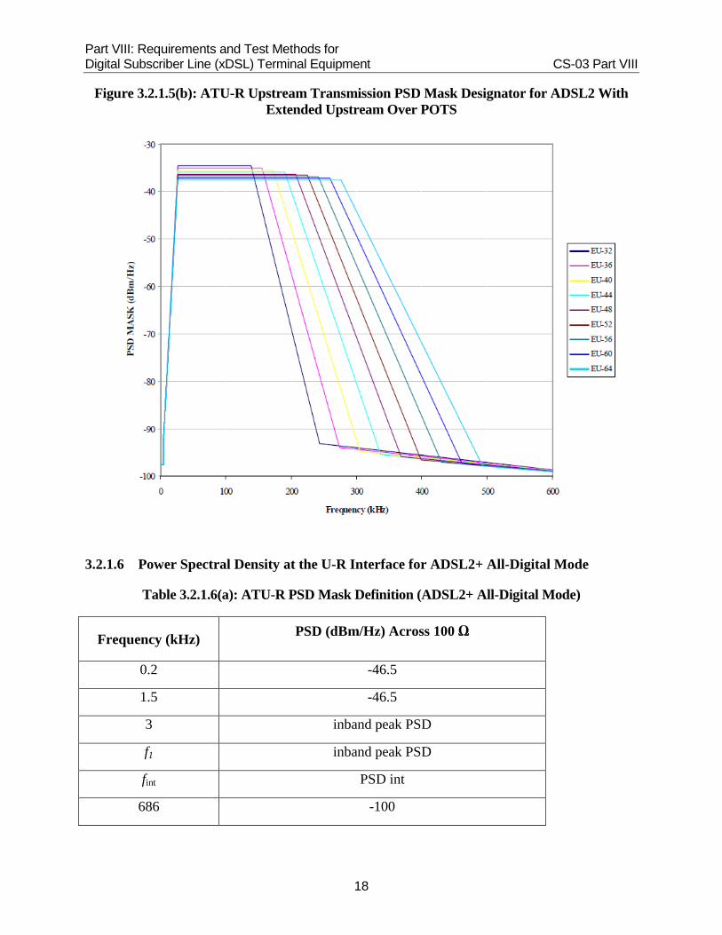
Figure 3.2.1.5(b): ATU-R Upstream Transmission PSD Mask Designator for ADSL2 With Extended Upstream Over POTS
3.2.1.6 Power Spectral Density at the U-R Interface for ADSL2+ All-Digital Mode
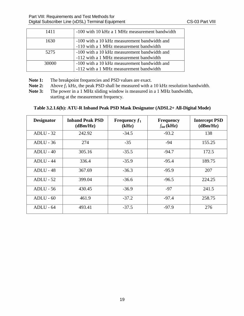
Table 3.2.1.6(a): ATU-R PSD Mask Definition (ADSL2+ All-Digital Mode)
Frequency (kHz) PSD (dBm/Hz) Across 100 Ω
0.2 -46.5
1.5 -46.5
3 inband peak PSD
f1 inband peak PSD
fint PSD int
686 -100
Part VIII: Requirements and Test Methods for Digital Subscriber Line (xDSL) Terminal Equipment CS-03 Part VIII
19
1411 -100 with 10 kHz a 1 MHz measurement bandwidth
1630 -100 with a 10 kHz measurement bandwidth and -110 with a 1 MHz measurement bandwidth
5275 -100 with a 10 kHz measurement bandwidth and -112 with a 1 MHz measurement bandwidth
30000 -100 with a 10 kHz measurement bandwidth and -112 with a 1 MHz measurement bandwidth
Note 1: The breakpoint frequencies and PSD values are exact. Note 2: Above f1 kHz, the peak PSD shall be measured with a 10 kHz resolution bandwidth. Note 3: The power in a 1 MHz sliding window is measured in a 1 MHz bandwidth,
starting at the measurement frequency.
Table 3.2.1.6(b): ATU-R Inband Peak PSD Mask Designator (ADSL2+ All-Digital Mode)
Designator
Inband Peak PSD (dBm/Hz)
Frequency ƒ1 (kHz)
Frequency fint (kHz)
Intercept PSD (dBm/Hz)
ADLU - 32 242.92 -34.5 -93.2 138
ADLU - 36 274 -35 -94 155.25
ADLU - 40 305.16 -35.5 -94.7 172.5
ADLU - 44 336.4 -35.9 -95.4 189.75
ADLU - 48 367.69 -36.3 -95.9 207
ADLU - 52 399.04 -36.6 -96.5 224.25
ADLU - 56 430.45 -36.9 -97 241.5
ADLU - 60 461.9 -37.2 -97.4 258.75
ADLU - 64 493.41 -37.5 -97.9 276

Part VIII: Requirements and Test Methods for Digital Subscriber Line (xDSL) Terminal Equipment CS-03 Part VIII
20
Figure 3.2.1.6(a): ATU-R Upstream Transmission PSD Mask for ADSL2+ All-Digital Mode

Part VIII: Requirements and Test Methods for Digital Subscriber Line (xDSL) Terminal Equipment CS-03 Part VIII
21
Figure 3.2.1.6(b): ATU-R Upstream Transmission PSD Mask Designator for ADSL2+ All-Digital Mode

Part VIII: Requirements and Test Methods for Digital Subscriber Line (xDSL) Terminal Equipment CS-03 Part VIII
22
3.2.1.7 Power Spectral Density at the U-R Interface for ADSL2+ Extended Upstream
Table 3.2.1.7(a): ATU-R PSD Mask Definition ADSL2+ Extended Upstream
Frequency (kHz) PSD (dBm/Hz) Across 100 Ω
0.2 -97.5
4 -97.5
4 -92.5
25.875 inband peak PSD
f1 inband peak PSD
fint PSDint
686 -100
1411 -100 with a 1 kHz measurement bandwidths
1630 -100 with a 10 MHz measurement bandwidth and -110 with a 1 MHz measurement bandwidth
5275 -100 with a 10 kHz measurement bandwidth and -112 with a 1 MHz measurement bandwidth
30000 -100 with a 10 kHz measurement bandwidth and -112 with a 1 MHz measurement bandwidth
Note 1: The breakpoint frequencies and PSD values are exact. Note 2: Above 25.875 kHz, the peak PSD shall be measured with a 10 kHz resolution
bandwidth. Note 3: The power in a 1 MHz sliding window is measured in a 1 MHz bandwidth, starting at
the measurement frequency.
Table 3.2.1.7(b): ATU-R Inband Peak PSD Mask Designator ADSL2+ Extended Upstream
Designator
Inband Peak PSD (dBm/Hz)
Frequency f1 (kHz)
Frequency fint (kHz)
Intercept PSD (dBm/Hz)
ADLU - 32 -34.5 138 242.92 -93.2
ADLU - 36 -35 155.25 274 -94
ADLU - 40 -35.5 172.5 305.16 -94.7
ADLU - 44 -35.9 189.75 336.4 -95.4
ADLU - 48 -36.3 207 367.69 -95.9

Part VIII: Requirements and Test Methods for Digital Subscriber Line (xDSL) Terminal Equipment CS-03 Part VIII
23
ADLU - 52 -36.6 224.25 399.04 -96.5
ADLU - 56 -36.9 241.5 430.45 -97
ADLU - 60 -37.2 258.75 461.9 -97.4
ADLU - 64 -37.5 276 493.41 -97.9
Figure 3.2.1.7(a): ATU-R Upstream Transmission PSD Mask for ADSL2+ Extended Upstream

Part VIII: Requirements and Test Methods for Digital Subscriber Line (xDSL) Terminal Equipment CS-03 Part VIII
24
Figure 3.2.1.7(b): ATU-R Upstream Transmission PSD Mask Designator for ADSL2+ Extended Upstream
Part VIII: Requirements and Test Methods for Digital Subscriber Line (xDSL) Terminal Equipment CS-03 Part VIII
25
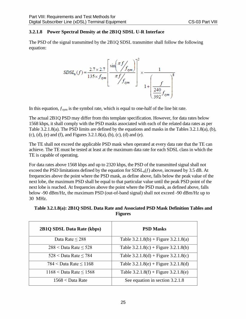
3.2.1.8 Power Spectral Density at the 2B1Q SDSL U-R Interface
The PSD of the signal transmitted by the 2B1Q SDSL transmitter shall follow the following equation:
In this equation, ƒsym is the symbol rate, which is equal to one-half of the line bit rate.
The actual 2B1Q PSD may differ from this template specification. However, for data rates below 1568 kbps, it shall comply with the PSD masks associated with each of the related data rates as per Table 3.2.1.8(a). The PSD limits are defined by the equations and masks in the Tables 3.2.1.8(a), (b), (c), (d), (e) and (f), and Figures 3.2.1.8(a), (b), (c), (d) and (e).
The TE shall not exceed the applicable PSD mask when operated at every data rate that the TE can achieve. The TE must be tested at least at the maximum data rate for each SDSL class in which the TE is capable of operating.
For data rates above 1568 kbps and up to 2320 kbps, the PSD of the transmitted signal shall not exceed the PSD limitations defined by the equation for SDSLu(ƒ) above, increased by 3.5 dB. At frequencies above the point where the PSD mask, as define above, falls below the peak value of the next lobe, the maximum PSD shall be equal to that particular value until the peak PSD point of the next lobe is reached. At frequencies above the point where the PSD mask, as defined above, falls below -90 dBm/Hz, the maximum PSD (out-of-band signal) shall not exceed -90 dBm/Hz up to 30 MHz.
Table 3.2.1.8(a): 2B1Q SDSL Data Rate and Associated PSD Mask Definition Tables and Figures
2B1Q SDSL Data Rate (kbps) PSD Masks
Data Rate ≤ 288 Table 3.2.1.8(b) + Figure 3.2.1.8(a)
288 < Data Rate ≤ 528 Table 3.2.1.8(c) + Figure 3.2.1.8(b)
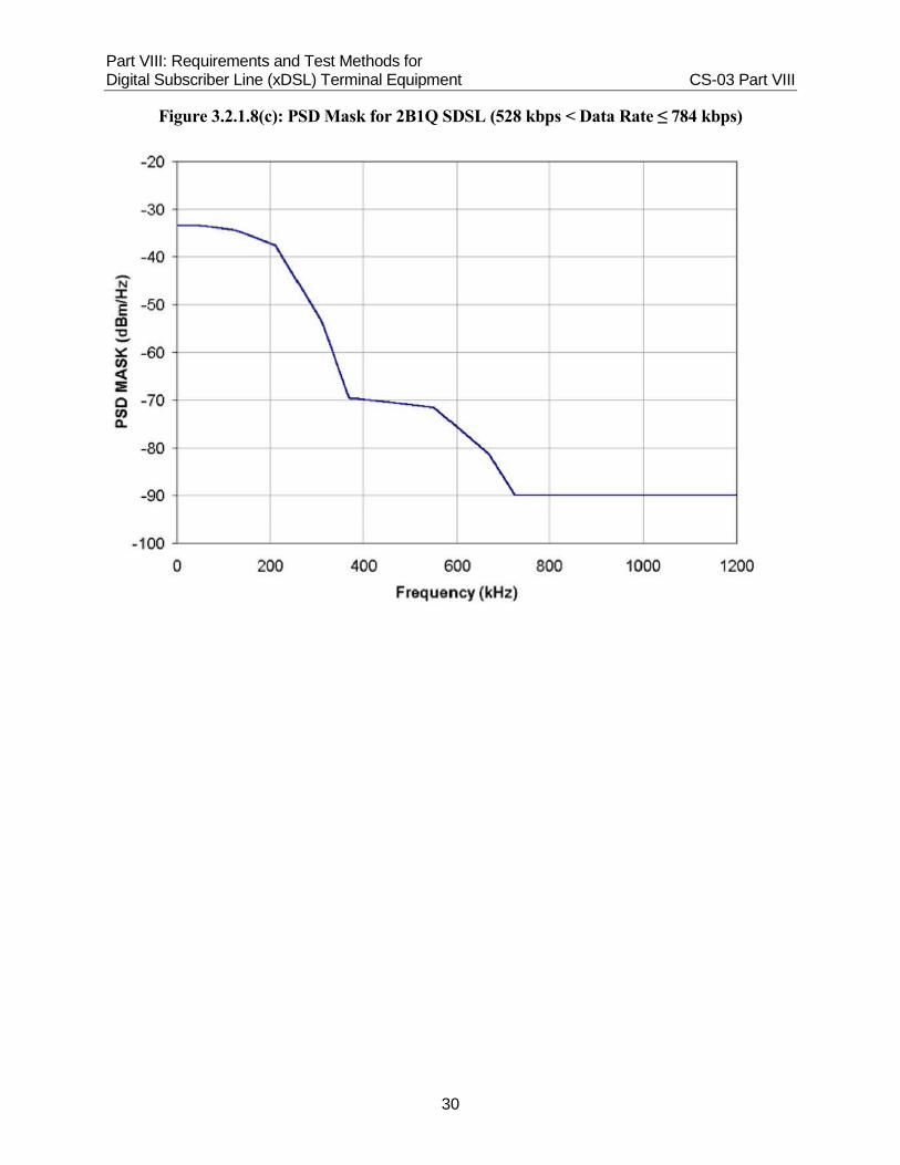
528 < Data Rate ≤ 784 Table 3.2.1.8(d) + Figure 3.2.1.8(c)
784 < Data Rate ≤ 1168 Table 3.2.1.8(e) + Figure 3.2.1.8(d)
1168 < Data Rate ≤ 1568 Table 3.2.1.8(f) + Figure 3.2.1.8(e)
1568 < Data Rate See equation in section 3.2.1.8

Part VIII: Requirements and Test Methods for Digital Subscriber Line (xDSL) Terminal Equipment CS-03 Part VIII
26
Table 3.2.1.8(b): 2B1Q SDSL (Data Rate ≤ 288 kbps) PSD Mask Definition
Frequency Band (kHz) PSD (dBm/Hz)
0.2 < ƒ ≤ 25 -29
25 < ƒ ≤ 76 -29 - 10.35 x log10(f/25)
76 < ƒ ≤ 79 -34 - 0.5 x ((f-76)/3)
79 < ƒ ≤ 85 -34.5 - 19.6 x log10((f-69)/10)
85 < ƒ ≤ 100 -38.5 - 4 x ((f-85)/15)
100 < ƒ ≤ 115 -42.5 - 7 x ((f-100)/15)
115 < ƒ ≤ 120 -49.5
120 < ƒ ≤ 225 -49.5 - 55 x log10(f/120)
225 < ƒ ≤ 520 -64.5 - 70 x log10(f/225)
520 < ƒ ≤ 30000 -90
Table 3.2.1.8(c): 2B1Q SDSL (288 kbps < Data Rate ≤ 528 kbps) PSD Mask Definition
Frequency (kHz) PSD (dBm/Hz)
0.2 -32.5
25 -32.5
75 -33
100 -35.5
150 -41.5
200 -50.5
230 -60.5
245 -67.5
335 -68.5
390 -72.5
440 -79.5
485 < ƒ ≤ 30000 -90

Part VIII: Requirements and Test Methods for Digital Subscriber Line (xDSL) Terminal Equipment CS-03 Part VIII
27
Table 3.2.1.8(d): 2B1Q SDSL (528 kbps < Data Rate ≤ 784 kbps) PSD Mask Definition
Frequency (kHz) PSD (dBm/Hz)
0.2 -33.5
50 -33.5
125 -34.5
210 -37.5
310 -53.5
370 -69.5
550 -71.5
670 -81.5
725 < ƒ ≤ 30000 -90
Table 3.2.1.8(e): 2B1Q SDSL (784 kbps < Data Rate ≤ 1168 kbps) PSD Mask Definition
Frequency (kHz) PSD (dBm/Hz)
0.2 -35.5
60 -35.5
200 -36.5
250 -37
315 -37.5
400 -49.5
500 -62.5
550 -71.5
750 -72.5
950 -80.5
1095 < ƒ ≤ 30000 -90

Part VIII: Requirements and Test Methods for Digital Subscriber Line (xDSL) Terminal Equipment CS-03 Part VIII
28
Table 3.2.1.8(f): 2B1Q SDSL (1168 kbps < Data Rate ≤ 1568 kbps) PSD Mask Definition
Frequency (kHz) PSD (dBm/Hz)
0.2 -36.5
100 -36.5
150 -37
200 -38
300 -38.5
390 -38.5
420 -39.5
500 -47.5
775 -73.5
1000 -73.5
1100 -76.5
1300 -82.5
1395 < ƒ ≤ 30000 -90
Part VIII: Requirements and Test Methods for Digital Subscriber Line (xDSL) Terminal Equipment CS-03 Part VIII
29
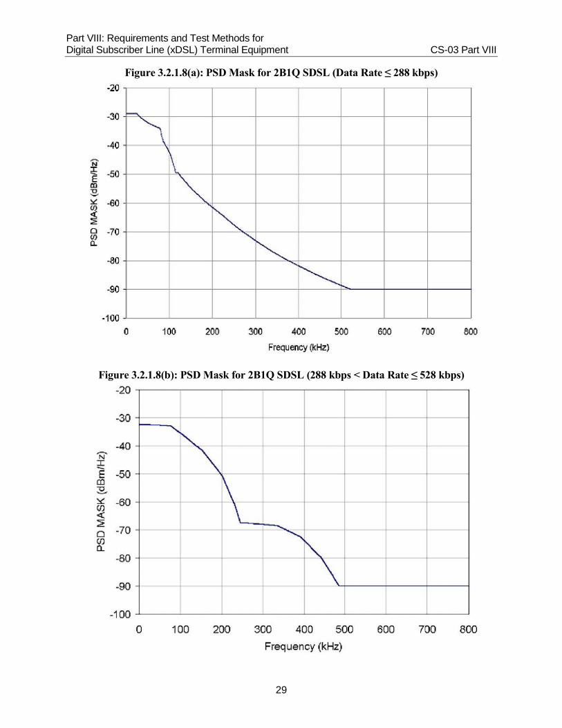
Figure 3.2.1.8(a): PSD Mask for 2B1Q SDSL (Data Rate ≤ 288 kbps)
Figure 3.2.1.8(b): PSD Mask for 2B1Q SDSL (288 kbps < Data Rate ≤ 528 kbps)
Part VIII: Requirements and Test Methods for Digital Subscriber Line (xDSL) Terminal Equipment CS-03 Part VIII
30
Figure 3.2.1.8(c): PSD Mask for 2B1Q SDSL (528 kbps < Data Rate ≤ 784 kbps)

Part VIII: Requirements and Test Methods for Digital Subscriber Line (xDSL) Terminal Equipment CS-03 Part VIII
31
Figure 3.2.1.8(d): PSD Mask for 2B1Q SDSL (784 kbps < Data Rate ≤ 1168 kbps)

Part VIII: Requirements and Test Methods for Digital Subscriber Line (xDSL) Terminal Equipment CS-03 Part VIII
32
Figure 3.2.1.8(e): PSD Mask for 2B1Q SDSL (1168 kbps < Data Rate ≤ 1568 kbps)
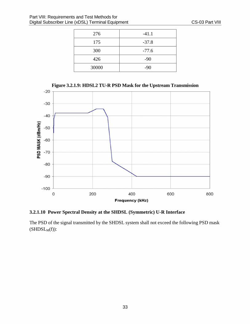
3.2.1.9 Power Spectral Density at the HDSL2 U-R Interface
The PSD of the HDSL2 transmit signal measured at the U-R interface shall not exceed the PSD mask defined in Table 3.2.1.9 and Figure 3.2.1.9.
Table 3.2.1.9: HDSL2 Mask Values for Spectral Shaper at the U-R Interface
Frequency (kHz) PSD (dBm/Hz)
≤1 -54.2
2 -42.1
10 -37.8
220 -34.4
255 -34.4
Part VIII: Requirements and Test Methods for Digital Subscriber Line (xDSL) Terminal Equipment CS-03 Part VIII
33
276 -41.1
175 -37.8
300 -77.6
426 -90
30000 -90
Figure 3.2.1.9: HDSL2 TU-R PSD Mask for the Upstream Transmission
3.2.1.10 Power Spectral Density at the SHDSL (Symmetric) U-R Interface
The PSD of the signal transmitted by the SHDSL system shall not exceed the following PSD mask (SHDSLM(f)):

Part VIII: Requirements and Test Methods for Digital Subscriber Line (xDSL) Terminal Equipment CS-03 Part VIII
34
ƒint is the frequency at which the two functions governing SHDSLM (ƒ) intersect in the range 0 to ƒsym. KSHDSL, ƒsym, ƒ3dB and the payload data rate R are defined in Table 3.2.1.10. At frequencies above the point where the PSD mask, as defined above, falls below the peak value of the next lobe, the maximum PSD shall be equal to that particular value until the peak PSD point of the next lobe is reached.
At frequencies above the point where the PSD mask, as defined above, falls below -90 dBm/Hz, the maximum PSD (out-of-band signal) shall not exceed -90 dBm/Hz up to 30 MHz.
The transmitted spectrum shall not exceed the applicable mask when the equipment is operated at any of the data rates specified in Annex A, Table A1(d). The TE must be tested at least at the maximum data rate for each designation shown in Annex A, Table A1(d), in which the TE is capable of operating.
Table 3.2.1.10: SHDSL Symmetric PSD Parameters
Line Bit Rate (LBR) (kbps)
KSHDSL
fsym (ksymbols/s)
f3dB
≠ 1544 or 1552
7.86 LBR / 3 1.0 xƒsym /2
= 1544 or 1552
8.32 LBR / 3 0.9 xƒsym /2
3.2.1.11 Power Spectral Density at the Extended SHDSL U-R Interface
The PSD of the signal transmitted by the extended SHDSL system shall not exceed the following PSD masks (SHDSLM(ƒ)):

Part VIII: Requirements and Test Methods for Digital Subscriber Line (xDSL) Terminal Equipment CS-03 Part VIII
35
The measured total power into 135 Ω shall not exceed +14 dBm. MaskOffsetdB(f) is defined as:
where: fint is the frequency at which the two functions governing SHDSLM(f) intersect in the range 0 to fsym; the variables KSHDSL, Order, N, fsym, and f3dB are as defined in tables 3.2.1.11(a) and 3.2.1.11(b); and R is the payload bit rate. The variables f, fsym, fint and f3dB in the equations are in units of hertz (Hz).
Table 3.2.1.11(a): Symmetric PSD Parameters, 16-TC-PAM
Payload Bit Rate (R) (kbit/s) KSHDSL Order N fsym
(ksymbol/s) f3dB (Hz)
2320 ≤ R ≤ 3840 7.86 6 1 (R+8)/3 1.0 x fsym/2

Part VIII: Requirements and Test Methods for Digital Subscriber Line (xDSL) Terminal Equipment CS-03 Part VIII
36
Table 3.2.1.11(b): Symmetric PSD Parameters, 32-TC-PAM
Payload Bit Rate(R) (kbit/s) KSHDSL Order N fsym
(ksymbol/s) f3dB (Hz)
768 ≤ R ≤ 5696 7.86 6 1 (R+8)/4 1.0 x fsym/2
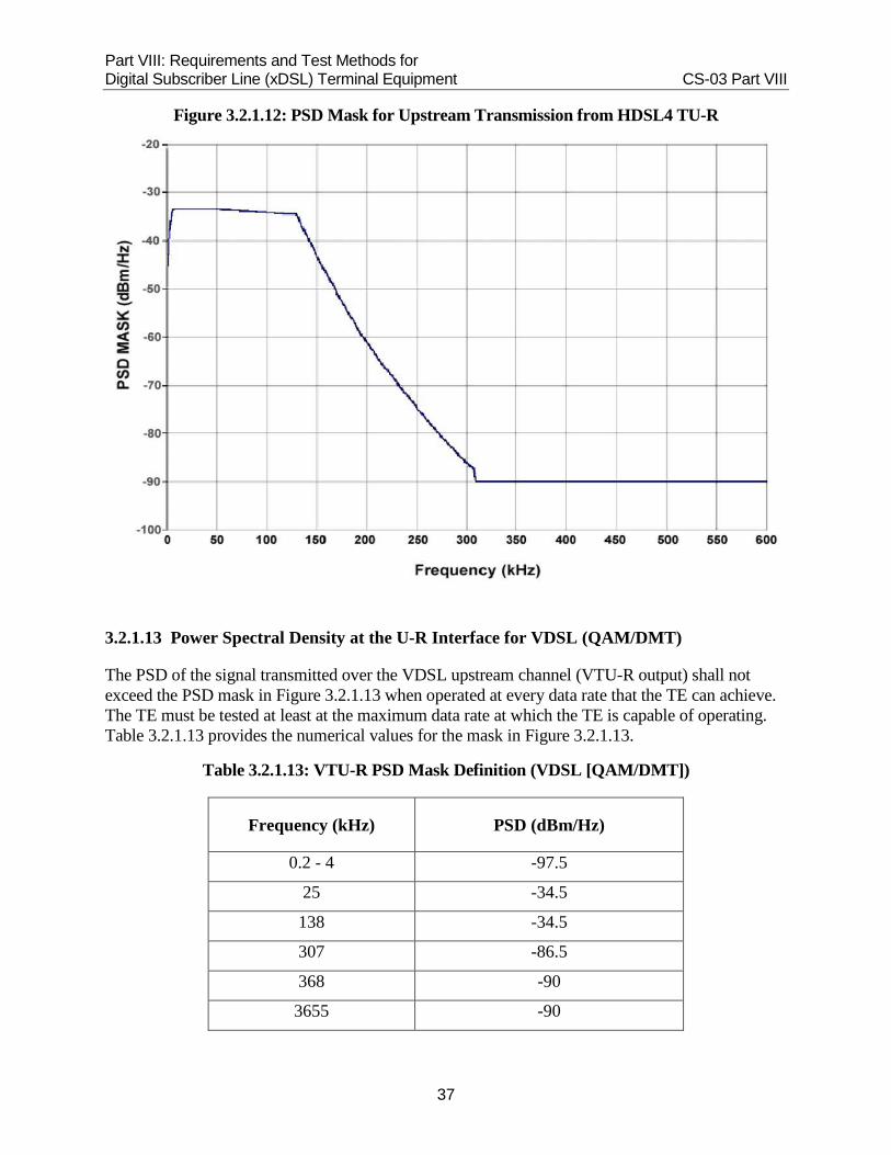
3.2.1.12 Power Spectral Density at the HDSL4 U-R Interface
The PSD of the HDSL4 transmit signal measured at the U-R interface shall not exceed the PSD mask defined in Table 3.2.1.12 and Figure 3.2.1.12.
Table 3.2.1.12: PSD Mask Definition for Upstream Transmission from HDSL4 TU
Frequency Band (kHz) PSD (dBm/Hz)
0 < ƒ ≤ 0.2 -47.5
0.2 < ƒ ≤ 2 -37.5 + 10(f-2)/1.8
2 < ƒ ≤ 5 -33.5 + 4(f-5)/3
5 < ƒ ≤ 50 -33.5
50 < ƒ ≤ 125 -33.5 - ((f-50)75)
125 < ƒ ≤ 130 -34.5
130 < ƒ ≤ 307 -34.5 - 142 x log10(f/130)
307 < ƒ ≤ 30000 -90
Part VIII: Requirements and Test Methods for Digital Subscriber Line (xDSL) Terminal Equipment CS-03 Part VIII
37
Figure 3.2.1.12: PSD Mask for Upstream Transmission from HDSL4 TU-R
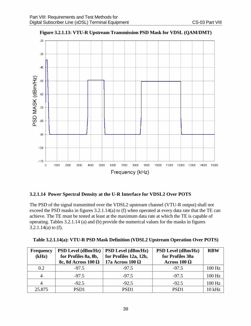
3.2.1.13 Power Spectral Density at the U-R Interface for VDSL (QAM/DMT)
The PSD of the signal transmitted over the VDSL upstream channel (VTU-R output) shall not exceed the PSD mask in Figure 3.2.1.13 when operated at every data rate that the TE can achieve. The TE must be tested at least at the maximum data rate at which the TE is capable of operating. Table 3.2.1.13 provides the numerical values for the mask in Figure 3.2.1.13.
Table 3.2.1.13: VTU-R PSD Mask Definition (VDSL [QAM/DMT])
Frequency (kHz) PSD (dBm/Hz)
0.2 - 4 -97.5
25 -34.5
138 -34.5
307 -86.5
368 -90
3655 -90

Part VIII: Requirements and Test Methods for Digital Subscriber Line (xDSL) Terminal Equipment CS-03 Part VIII
38
3750 -76.5
3751 -49.5
5199 -49.5
5200 -76.5
5287 -90
8412 -90
8500 -76.5
8501 -50.5
11999 -50.5
12000 -76.5
12087 -90
30000 -90
Part VIII: Requirements and Test Methods for Digital Subscriber Line (xDSL) Terminal Equipment CS-03 Part VIII
39
Figure 3.2.1.13: VTU-R Upstream Transmission PSD Mask for VDSL (QAM/DMT)
3.2.1.14 Power Spectral Density at the U-R Interface for VDSL2 Over POTS
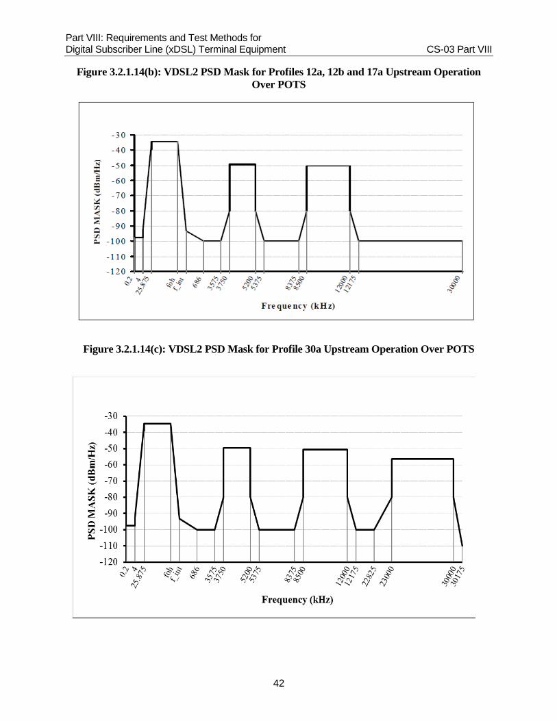
The PSD of the signal transmitted over the VDSL2 upstream channel (VTU-R output) shall not exceed the PSD masks in figures 3.2.1.14(a) to (f) when operated at every data rate that the TE can achieve. The TE must be tested at least at the maximum data rate at which the TE is capable of operating. Tables 3.2.1.14 (a) and (b) provide the numerical values for the masks in figures 3.2.1.14(a) to (f).
Table 3.2.1.14(a): VTU-R PSD Mask Definition (VDSL2 Upstream Operation Over POTS)
Frequency (kHz)
PSD Level (dBm/Hz) for Profiles 8a, 8b,
8c, 8d Across 100 Ω
PSD Level (dBm/Hz) for Profiles 12a, 12b, 17a Across 100 Ω
PSD Level (dBm/Hz) for Profiles 30a Across 100 Ω
RBW
0.2 -97.5 -97.5 -97.5 100 Hz 4 -97.5 -97.5 -97.5 100 Hz 4 -92.5 -92.5 -92.5 100 Hz
25.875 PSD1 PSD1 PSD1 10 kHz

Part VIII: Requirements and Test Methods for Digital Subscriber Line (xDSL) Terminal Equipment CS-03 Part VIII
40
fOH PSD1 PSD1 PSD1 10 kHz fint PSDint PSDint PSDint 10 kHz 686 -100 -100 -100 10 kHz 3575 -100 -100 -100 10 kHz 3750 -80 -80 -80 10 kHz 3750 -49.5 -49.5 -49.5 10 kHz 5200 -49.5 -49.5 -49.5 10 kHz 5200 -80 -80 -80 10 kHz 5375 -100 -100 -100 10 kHz 8375 -100 -100 -100 10 kHz 8500 -100 -80 -80 10 kHz 8500 -100 -50.5 -50.5 10 kHz 12000 -100 -50.5 -50.5 10 kHz 12000 -100 -80 -80 10 kHz 12175 -100 -100 -100 10 kHz 22825 -100 -100 -100 10 kHz 23000 -100 -100 -80 10 kHz 23000 -100 -100 -56.5 10 kHz 30000 -100 -100 -56.5 10 kHz 30000 - - -80 10 kHz 30175 - - -110 10 kHz
Table 3.2.1.14(b): VTU-R Inband Peak PSD1, PSDint and the Frequencies fOH and fint (VDSL2 Upstream Operation Over POTS)
Upstream Mask-
Number Designator
PSD1 (dBm/Hz)
Frequency fOH
(kHz)
Intercept Frequency
fint (kHz)
Intercept PSD Level PSDint
(dBm/Hz)
1 ADLU - 32 -34.5 138 242.92 -93.2 2 ADLU - 36 -35 155.25 274 -94 3 ADLU - 40 -35.5 172.5 305.16 -94.7 4 ADLU - 44 -35.9 189.75 336.4 -95.4 5 ADLU - 48 -36.3 207 367.69 -95.9 6 ADLU - 52 -36.6 224.25 399.04 -96.5 7 ADLU - 56 -36.9 241.5 430.45 -97

Part VIII: Requirements and Test Methods for Digital Subscriber Line (xDSL) Terminal Equipment CS-03 Part VIII
41
8 ADLU - 60 -37.2 258.75 461.9 -97.4 9 ADLU - 64 -37.5 276 493.41 -97.9
Note: EU-32 through EU-64 shall not be used in conjunction with EU-128.
Figure 3.2.1.14(a): VDSL2 PSD Mask for Profiles 8a, 8b, 8c and 8d Upstream Operation Over POTS
Part VIII: Requirements and Test Methods for Digital Subscriber Line (xDSL) Terminal Equipment CS-03 Part VIII
42
Figure 3.2.1.14(b): VDSL2 PSD Mask for Profiles 12a, 12b and 17a Upstream Operation Over POTS
Figure 3.2.1.14(c): VDSL2 PSD Mask for Profile 30a Upstream Operation Over POTS

Part VIII: Requirements and Test Methods for Digital Subscriber Line (xDSL) Terminal Equipment CS-03 Part VIII
43
Table 3.2.1.14(c) - VDSL2 EU-128 PSD Mask Limits for Profiles 8a, 8b, 8c, 8d, 12a, 12b, 17a and 30a Upstream Operation Over POTS
Frequency (kHz)
PSD Level (dBm/Hz) for
Profiles 8a, 8b, 8c, 8d Across
100 Ω
PSD Level (dBm/Hz) for
Profiles 12a, 12b, 17a Across 100 Ω
PSD Level (dBm/Hz) for Profiles 30a
Across 100 Ω
RBW
0.2 -97.5 -97.5 -97.5 100 Hz
4 -97.5 -97.5 -97.5 100 Hz 4 -92.5 -92.5 -92.5 100 Hz
25.875 -34.5 -34.5 -34.5 10 kHz
138 -34.5 -34.5 -34.5 10 kHz 552 -40.6 -40.6 -40.6 10 kHz 989 -100 -100 -100 10 kHz 3575 -100 -100 -100 10 kHz 3750 -80 -80 -80 10 kHz 3750 -49.5 -49.5 -49.5 10 kHz 5200 -49.5 -49.5 -49.5 10 kHz 5200 -80 -80 -80 10 kHz 5375 -100 -100 -100 10 kHz
8375 -100 -100 -100 10 kHz 8500 -100 -80 -80 10 kHz 8500 -100 -50.5 -50.5 10 kHz 12000 -100 -50.5 -50.5 10 kHz 12000 -100 -80 -80 10 kHz 12175 -100 -100 -100 10 kHz 22825 -100 -100 -100 10 kHz 23000 -100 -100 -80 10 kHz 23000 -100 -100 -56.5 10 kHz 30000 -100 -100 -56.5 10 kHz 30000 - - -80 10 kHz 30175 -110 -110 -110 10 kHz

Part VIII: Requirements and Test Methods for Digital Subscriber Line (xDSL) Terminal Equipment CS-03 Part VIII
44
Figure 3.2.1.14(d): VDSL2 EU-128 PSD Mask for Profiles 8a, 8b, 8c and 8d Upstream Operation Over POTS
Figure 3.2.1.14(e): VDSL2 EU-128 PSD Mask for Profiles 12a, 12b and 17a Upstream Operation Over POTS

Part VIII: Requirements and Test Methods for Digital Subscriber Line (xDSL) Terminal Equipment CS-03 Part VIII
45
Figure 3.2.1.14(f): VDSL2 EU-128 PSD Mask for Profile 30a Upstream Operation Over POTS
3.2.1.15 Power Spectral Density at the U-R Interface for VDSL2 All-Digital Mode
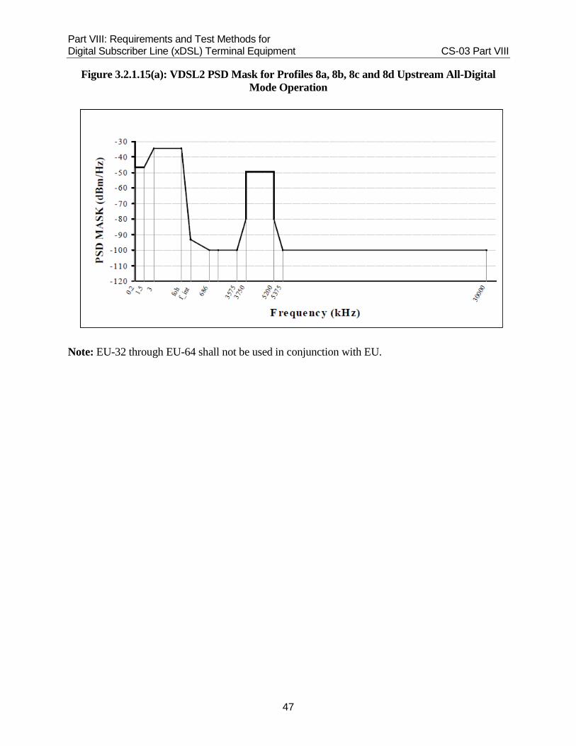
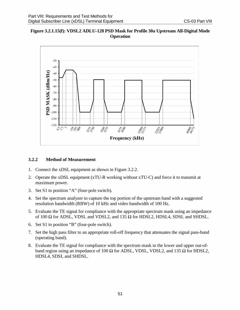
The PSD of the signal transmitted over the VDSL2 upstream channel (VTU-R output) shall not exceed the PSD masks in figures 3.2.1.15(a) to (f) when operated at every data rate that the TE can achieve. The TE must be tested at least at the maximum data rate at which the TE is capable of operating. Tables 3.2.1.15 (a) and (b) provide the numerical values for the masks in figures 3.2.1.15(a) to (f).
Table 3.2.1.15(a): VTU-R PSD Mask Definition (VDSL2 Upstream Operation All-Digital Mode)
Frequency (kHz)
PSD Level (dBm/Hz) for Profiles 8a, 8b, 8c,
8d Across 100 Ω
PSD Level (dBm/Hz) for Profiles 12a, 12b,
17a Across 100 Ω
PSD Level (dBm/Hz) for Profiles 30a Across 100 Ω
RBW
0.2 -46.5 -46.5 -46.5 100 Hz 1.5 -46.5 -46.5 -46.5 100 Hz 3 PSD1 PSD1 PSD1 100 Hz
fOH PSD1 PSD1 PSD1 10 kHz fint PSDint PSDint PSDint 10 kHz 686 -100 -100 -100 10 kHz
Part VIII: Requirements and Test Methods for Digital Subscriber Line (xDSL) Terminal Equipment CS-03 Part VIII
46
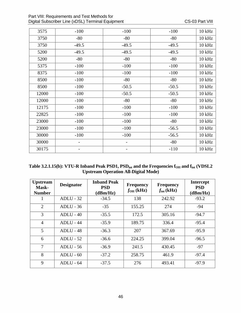
Table 3.2.1.15(b): VTU-R Inband Peak PSD1, PSDint and the Frequencies fOH and fint (VDSL2 Upstream Operation All-Digital Mode)
Upstream Mask-
Number
Designator
Inband Peak PSD
(dBm/Hz)
Frequency fOH (kHz)
Frequency fint (kHz)
Intercept PSD
(dBm/Hz) 1 ADLU - 32 -34.5 138 242.92 -93.2
2 ADLU - 36 -35 155.25 274 -94
3 ADLU - 40 -35.5 172.5 305.16 -94.7
4 ADLU - 44 -35.9 189.75 336.4 -95.4
5 ADLU - 48 -36.3 207 367.69 -95.9
6 ADLU - 52 -36.6 224.25 399.04 -96.5
7 ADLU - 56 -36.9 241.5 430.45 -97
8 ADLU - 60 -37.2 258.75 461.9 -97.4
9 ADLU - 64 -37.5 276 493.41 -97.9
3575 -100 -100 -100 10 kHz 3750 -80 -80 -80 10 kHz 3750 -49.5 -49.5 -49.5 10 kHz 5200 -49.5 -49.5 -49.5 10 kHz 5200 -80 -80 -80 10 kHz 5375 -100 -100 -100 10 kHz 8375 -100 -100 -100 10 kHz 8500 -100 -80 -80 10 kHz 8500 -100 -50.5 -50.5 10 kHz 12000 -100 -50.5 -50.5 10 kHz 12000 -100 -80 -80 10 kHz 12175 -100 -100 -100 10 kHz 22825 -100 -100 -100 10 kHz 23000 -100 -100 -80 10 kHz 23000 -100 -100 -56.5 10 kHz 30000 -100 -100 -56.5 10 kHz 30000 - - -80 10 kHz 30175 - - -110 10 kHz
Part VIII: Requirements and Test Methods for Digital Subscriber Line (xDSL) Terminal Equipment CS-03 Part VIII
47
Figure 3.2.1.15(a): VDSL2 PSD Mask for Profiles 8a, 8b, 8c and 8d Upstream All-Digital Mode Operation
Note: EU-32 through EU-64 shall not be used in conjunction with EU.

Part VIII: Requirements and Test Methods for Digital Subscriber Line (xDSL) Terminal Equipment CS-03 Part VIII
48
Figure 3.2.1.15(b): VDSL2 PSD Mask for Profiles 12a, 12b and 17a Upstream All-Digital Mode Operation
Figure 3.2.1.15(c): VDSL2 PSD Mask for Profile 30a Upstream All-Digital Mode Operation

Part VIII: Requirements and Test Methods for Digital Subscriber Line (xDSL) Terminal Equipment CS-03 Part VIII
49
Table 3.2.1.15(c): VDSL2 ADLU-128 PSD Mask Limits for Profiles 8a, 8b, 8c, 8d, 12a, 12b, 17a and 30a Upstream All-Digital Mode Operation
Frequency (kHz)
PSD Level (dBm/Hz) for
Profiles 8a, 8b, 8c, 8d Across
100 Ω
PSD Level (dBm/Hz) for
Profiles 12a, 12b, 17a Across 100 Ω
PSD Level (dBm/Hz) for Profiles 30a
Across 100 Ω
RBW
0.2 -46.5 -46.5 -46.5 100 Hz 1.5 -46.5 -46.5 -46.5 100 Hz 3 -34.5 -34.5 -34.5 100 Hz
138 -34.5 -34.5 -34.5 10 kHz 552 -40.6 -40.6 -40.6 10 kHz 989 -100 -100 -100 10 kHz 3575 -100 -100 -100 10 kHz 3750 -80 -80 -80 10 kHz 3750 -49.5 -49.5 -49.5 10 kHz 5200 -49.5 -49.5 -49.5 10 kHz 5200 -80 -80 -80 10 kHz 5375 -100 -100 -100 10 kHz 8375 -100 -100 -100 10 kHz 8500 -100 -80 -80 10 kHz 8500 -100 -50.5 -50.5 10 kHz 12000 -100 -50.5 -50.5 10 kHz 12000 -100 -80 -80 10 kHz 12175 -100 -100 -100 10 kHz 22825 -100 -100 -100 10 kHz 23000 -100 -100 -80 10 kHz 23000 -100 -100 -56.5 10 kHz 30000 -100 -100 -56.5 10 kHz 30000 - - -80 10 kHz 30175 - - -110 10 kHz

Part VIII: Requirements and Test Methods for Digital Subscriber Line (xDSL) Terminal Equipment CS-03 Part VIII
50
Figure 3.2.1.15(d): VDSL2 ADLU-128 PSD Mask for Profiles 8a, 8b, 8c and 8d Upstream All-Digital Mode Operation
Figure 3.2.1.15(e): VDSL2 ADLU-128 PSD Mask for Profiles 12a, 12b and 17a Upstream All-Digital Mode Operation
Part VIII: Requirements and Test Methods for Digital Subscriber Line (xDSL) Terminal Equipment CS-03 Part VIII
51
Figure 3.2.1.15(f): VDSL2 ADLU-128 PSD Mask for Profile 30a Upstream All-Digital Mode Operation
3.2.2 Method of Measurement
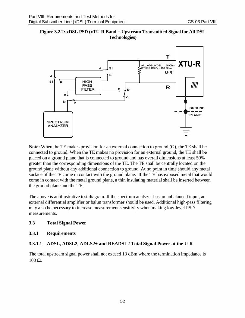
1. Connect the xDSL equipment as shown in Figure 3.2.2.
2. Operate the xDSL equipment (xTU-R working without xTU-C) and force it to transmit at maximum power.
3. Set S1 to position “A” (four-pole switch).
4. Set the spectrum analyzer to capture the top portion of the upstream band with a suggested resolution bandwidth (RBW) of 10 kHz and video bandwidth of 100 Hz.
5. Evaluate the TE signal for compliance with the appropriate spectrum mask using an impedance of 100 Ω for ADSL, VDSL and VDSL2, and 135 Ω for HDSL2, HDSL4, SDSL and SHDSL.
6. Set S1 to position “B” (four-pole switch).
7. Set the high pass filter to an appropriate roll-off frequency that attenuates the signal pass-band (operating band).
8. Evaluate the TE signal for compliance with the spectrum mask in the lower and upper out-of-band region using an impedance of 100 Ω for ADSL, VDSL, VDSL2, and 135 Ω for HDSL2, HDSL4, SDSL and SHDSL.
Part VIII: Requirements and Test Methods for Digital Subscriber Line (xDSL) Terminal Equipment CS-03 Part VIII
52
Figure 3.2.2: xDSL PSD (xTU-R Band = Upstream Transmitted Signal for All DSL Technologies)
Note: When the TE makes provision for an external connection to ground (G), the TE shall be connected to ground. When the TE makes no provision for an external ground, the TE shall be placed on a ground plane that is connected to ground and has overall dimensions at least 50% greater than the corresponding dimensions of the TE. The TE shall be centrally located on the ground plane without any additional connection to ground. At no point in time should any metal surface of the TE come in contact with the ground plane. If the TE has exposed metal that would come in contact with the metal ground plane, a thin insulating material shall be inserted between the ground plane and the TE. The above is an illustrative test diagram. If the spectrum analyzer has an unbalanced input, an external differential amplifier or balun transformer should be used. Additional high-pass filtering may also be necessary to increase measurement sensitivity when making low-level PSD measurements.
3.3 Total Signal Power
3.3.1 Requirements
3.3.1.1 ADSL, ADSL2, ADLS2+ and READSL2 Total Signal Power at the U-R
The total upstream signal power shall not exceed 13 dBm where the termination impedance is 100 Ω.

Part VIII: Requirements and Test Methods for Digital Subscriber Line (xDSL) Terminal Equipment CS-03 Part VIII
53
3.3.1.2 2B1Q SDSL Total Signal Power
The TE must be tested at least at the maximum data rate for each spectrum management class in which the TE is capable of operating.
The equipment must comply with the applicable power limit when operated at every data rate that the TE can achieve.
Excluding remote power feeding, the average power of a signal consisting of equiprobable symbols in all positions shall not exceed 14 dBm over the frequency band of 0 Hz to symbol frequency (which is equal to one-half of the line bit rate) into a termination of 135 Ω.
3.3.1.3 HDSL2 Total Signal Power
The total average transmit power may be tested while span powered or locally powered as required by the intended application of the TE. For span powered applications, if the TE is an HDSL2 TU-R, the test shall be performed with power (DC voltage) applied at the loop interface (tip/ring) by an external voltage source feeding through an AC blocking impedance. The test circuit must contain provisions for DC power feed and possibly transformer isolation for the measurement instrumentation. The DC current source/sink must present a high impedance (at signal frequencies) to common ground.
The total average transmit power of the HDSL2 TU-R (into 135 Ω) below 350 kHz shall not exceed 17.0 dBm.
3.3.1.4 SHDSL (Symmetric) and Extended SHDSL (ESHDSL) Total Signal Power
The total average signal power below fsym transmitted by the SHDSL and ESHDSL TU-R shall not exceed 14 dBm, where the termination impedance is 135 Ω.
3.3.1.5 HDSL4 Total Signal Power at the U-R Interface
The total signal power transmitted by HDSL4 TU-R below 307 kHz shall not exceed 14.6 dBm, where the termination impedance is 135 Ω.
3.3.1.6 VDSL (QAM/DMT) and VDSL2 Total Signal Power at the U-R Interface Points
The total upstream signal power transmitted by VDSL (QAM/DMT) and VDSL2 TU-R shall not exceed 14.5 dBm when operated at every data rate that the TE can achieve, where the termination impedance is 100 Ω. The TE must be tested at least at the maximum data rate at which the TE is capable of operating.
3.3.2 Method of Measurement of Total Signal Power for All DSL Technologies
The total average transmit power may be tested while the TE is span-powered or locally powered, as required by the intended application of the TE. For span-powered applications, if the TE is a TU-R, the test shall be performed with the DC power applied at the loop interface by an external voltage source feeding through an AC blocking impedance. The DC current source/sink must present a high impedance (at signal frequencies) to common ground.

Part VIII: Requirements and Test Methods for Digital Subscriber Line (xDSL) Terminal Equipment CS-03 Part VIII
54
1. Connect the xDSL equipment as shown in Figure 3.2.2.
2. Set the spectrum analyzer to capture the upstream band with a suggested resolution bandwidth of 1 kHz and video bandwidth of 100 Hz.
3. Measure and record the nominal 3 dB roll off points.
4. Connect the xDSL equipment as shown in Figure 3.3.2.
5. Operate the xDSL equipment (xTU-R working without xTU-C) and force it to transmit at maximum power.
6. Use the appropriate band pass filter for xTU-R (upstream lower and upper 3 dB points). Measure and record the total signal power in dBm with a termination impedance of 100 Ω for ADSL, VDSL and VDSL2, and 135 Ω for all other DSL types.
Figure 3.3.2: xDSL Total Signal Power (xTU-R Band = Upstream Transmitted Signal for All DSL Technologies)
Band pass filter: xTU-R band Attenuation slope = 24 dB/Octave Insertion loss 0 dB ±0.5 dB Input impedance = 100 kΩ minimum in parallel with 50 pF maximum Output impedance = 50 Ω Hum and noise = 100 uVrms maximum

Part VIII: Requirements and Test Methods for Digital Subscriber Line (xDSL) Terminal Equipment CS-03 Part VIII
55
Note: When the TE makes provision for an external connection to ground (G), the TE shall be connected to ground. When the TE makes no provision for an external ground, the TE shall be placed on a ground plane that is connected to ground and has overall dimensions at least 50% greater than the corresponding dimensions of the TE. The TE shall be centrally located on the ground plane without any additional connection to ground. At no point in time should any metal surface of the TE come in contact with the ground plane. If the TE has exposed metal that would come in contact with the metal ground plane, a thin insulating material shall be inserted between the ground plane and the TE.
The above is an illustrative test diagram. If the spectrum analyzer has an unbalanced input, an external differential amplifier or balun transformer should be used. Additional high-pass filtering may also be necessary to increase measurement sensitivity when making low-level PSD measurements.
3.4 Transverse Balance
3.4.1 Requirements
The transverse balance of the TU-R shall exceed the values in Table 3.4.2 over the voice band from 200 Hz to 4000 Hz and over the entire range of frequencies between the lower and upper -20 dB points (relative to peak PSD) of the signal pass band as determined from the appropriate DSL PSD mask, with the ZL, ZM and VM set to the values defined in tables 3.4.3(a) to 3.4.3(e). Note 1: When using the actual -20 dB points from the transmitted signal to define the frequency
range, the TE shall be transmitting at maximum power. Note 2: Table 3.4.2 specifies the limits for the entire frequency range. The TE must only be
tested to the applicable frequency range, which in most cases is between 200 Hz and 4 kHz (voice band) and from 12 kHz to 30 MHz (-20 dB points). All other frequency ranges below or above the -20 dB points are not applicable even if shown in Table 3.4.2.
Transverse balance is a comparison of the voltage of a transmitted metallic signal to the voltage of any resulting longitudinal signal. It is defined in dB as: Transverse balance M - L = 20 log10[VM(ƒ)/VL(ƒ)] where: VM(ƒ) is the metallic voltage at frequency ƒ applied across tip and ring conductors of the port under test by a balanced source with metallic impedance ZM; and VL(ƒ) is the resultant longitudinal voltage appearing across a longitudinal impedance ZL. The greater the VM to VL ratio, the better the transverse balance of the transceiver unit and the less likely that it will contribute to a crosstalk interference problem. When calibrating the testing arrangement, the source metallic voltage should equal VM when a metallic termination of ZM is

Part VIII: Requirements and Test Methods for Digital Subscriber Line (xDSL) Terminal Equipment CS-03 Part VIII
56
substituted for the equipment under test. For all the different types of DSL, refer to tables 3.4.3(a) to 3.4.3(e) to find the correct values for metallic impedance ZM, longitudinal impedance ZL and metallic voltage VM.
3.4.2 Method of Measurement
1. Connect the TE as shown in Figure 3.4.3.
2. Set the spectrum analyzer / tracking generator to sweep the appropriate frequency range. Refer to Table 3.4.2 for the frequency bands. If the actual -20 dB points from the transmitted signal are used to define the frequency range, the TE shall be transmitting at maximum power.
3. Adjust the tracking generator voltage to the appropriate value for the type of DSL under test, across the calibration test resistor R3, using switch S1. Refer to tables 3.4.3(a) to 3.4.3(e) for the correct values.
4. Connect the detector across resistor R2.
5. Adjust the differential trimmer capacitor until a minimum voltage across resistor R2 is obtained. This represents the highest degree to which the bridge can be balanced, and this balance measurement must be at least 20 dB better than the requirement for the applicable frequency band. If this degree of balance cannot be attained, further attention should be given to the component selection and the construction of the test circuit.
6. Reverse the polarity using switch S3. If the longitudinal voltage (EL) changes by less than 1 dB, the calibration is acceptable. If the longitudinal voltage changes by more than 1 dB, it indicates the bridge needs further adjustment to be sufficiently balanced to accurately measure the TE. Repeat the calibration process until the measurements differ by less than 1 dB while maintaining the 20 dB minimum balance noted in step 5 above.
7. Replace the calibration resistor with the TE, using switches S1 and S2.
8. Measure the voltage across the tip and ring of the TE. This is the metallic reference voltage (EM).
9. Measure the voltage across resistor R2. This is the longitudinal voltage (EL).
10. Calculate the balance using the following formula: Balance M/L (dB) = 20 log10 (VM/VL)
Note 1: If the readings are taken in dBV, then the equation can be simplified to the following: Balance M/L (dB) = VM (dBV) - VL (dBV) Note 2: TE that is not normally grounded should be set in its normal at-rest position directly on
a grounded plane whose overall dimensions are at least 50% greater than the footprint of the TE. From a transverse balance standpoint, this represents a worst-case condition (i.e. the closest proximity to ground that is likely to be encountered by the TE).
Note 3: Transverse balance may be measured while the TE is line powered or locally powered.
If the TE is line powered then the test circuit shall contain a DC voltage source. The test shall be performed with the appropriate DC voltage source applied between the tip and ring conductors through an AC blocking impedance. The DC current source or sink

Part VIII: Requirements and Test Methods for Digital Subscriber Line (xDSL) Terminal Equipment CS-03 Part VIII
57
must present high impedance (at signal frequencies) to common ground. In line powered applications, the test circuit shall contain provisions for isolation of the measurement instrumentation from unintentional circuit paths through the common ground of the instrumentation and the TE power feed circuitry.
Table 3.4.2: Minimum Transverse Balance Requirements
Frequency Band (kHz) Minimum Transverse Balance
200 Hz <IJ 12 kHz 40 dB
12 kHz <IJ 1544 kHz 35 dB
1544 kHz <IJ 12 MHz 30 dB
12 MHz <IJ 30 MHz 25 dB
Note: Any range of frequency between the voice band (200 Hz to 4 kHz) and the lower -20 dB point, and any range of frequency above the upper -20 dB point are not applicable, even if shown in Table 3.4.2.
3.4.3 Transverse Balance Testing Criteria
Table 3.4.3(a): Frequency Range of Transverse Balance Requirements for ADLS Over POTS
Interface
Frequency Range (kHz)
Longitudinal Termination
(ZL) (Ω)
Metallic Termination
(ZM) (Ω)
Metallic Voltage (VM) (V)
ADSL 13.6 to 1625 90 100 0.316
ADSL2 13.6 to 1625 90 100 0.316
READSL 13.6 to 1625 90 100 0.316
ADSL2+ 13.6 to 2425 90 100 0.316
Table 3.4.3(b): Frequency Range of Transverse Balance Requirements for ADSL All-Digital Mode Equipment
Interface
Frequency Range (kHz)
Longitudinal Termination
(ZL) (Ω)
Metallic Termination
(ZM) (Ω)
Metallic Voltage (VM) (V)
ADSL2 0.2 to 2425 90 or 500 100 0.316
ADSL2+ 0.2 to 2425 90 or 500 100 0.316

Part VIII: Requirements and Test Methods for Digital Subscriber Line (xDSL) Terminal Equipment CS-03 Part VIII
58
Table 3.4.3(c): Frequency Range of Transverse Balance Requirements for SHDSL, ESHDSL, HDSL2 and HDSL4 Equipment
Interface
Frequency Range (kHz)
Longitudinal Termination
(ZL) (Ω)
Metallic Termination
(ZM) (Ω)
Metallic Voltage (VM) (V)
SHDSL 0.2 to 490 90 or 500 135 0.367 ESHDSL 0.2 to 761 90 or 500 135 0.367 HDSL2 0.2 to 422 90 or 500 135 0.367 HDSL4 0.2 to 494 90 or 500 135 0.367
Table 3.4.3(d): Frequency Range of Transverse Balance requirements for 2B1Q SDSL
Table 3.4.3(e): Frequency Range of Transverse Balance Requirements for VDSL and
VDSL2
Note: The longitudinal impedance (ZL) shall be 500 Ω for frequencies from 200 Hz to 12 kHz and 90 Ω for frequencies above 12 kHz.
Interface
Frequency Range (kHz)
Longitudinal Termination
(ZL) (Ω)
Metallic Termination
(ZM) (Ω)
Metallic Voltage (VM) (V)
2B1Q SDSL 0.2 to 575 90 or 500 135 0.367
Interface
Frequency Range (kHz)
Longitudinal Termination
(ZL) (Ω) (Note)
Metallic Termination
(ZM) (Ω)
Metallic Voltage (VM) (V)
VDSL over POTS 13.6 to 12000 90 100 0.316
VDSL2 over POTS profiles 8a, 8b, 8c, and 8d
13.6 to 8500 90 100 0.316
VDSL2 over POTS profiles 12a and 12b
13.6 to 12000 90 100 0.316
VDSL2 over POTS profiles 17a
13.6 to 20500 90 100 0.316
VDSL2 over POTS profile 30a
13.6 to 30000 90 100 0.316
VDSL2 all-digital mode profiles 8a, 8b, 8c, and 8d
0.2 to 8500 90/500 100 0.316
VDSL2 all-digital mode profiles 12a and 12b
0.2 to 12000 90/500 100 0.316
VDSL2 all-digital mode profile 17a
0.2 to 20500 90/500 100 0.316
VDSL2 all-digital mode profile 30a
0.2 to 30000 90/500 100 0.316

Part VIII: Requirements and Test Methods for Digital Subscriber Line (xDSL) Terminal Equipment CS-03 Part VIII
59
Figure 3.4.3: Illustrative Test Configuration for Transverse Balance Conformance Testing
Notes: 1. The combined resistance of R1 and the tracking generator output resistance shall equal the TE
impedance (100 or 135 Ω). 2. Use a center-tapped 1:1 transformer (e.g. Midcom 671-5767 or equivalent). 3. R2 provides the desired longitudinal impedance using 90- or 500 Ω metal film or other
non-inductive resistor. 4. High impedance spectrum analyzer or frequency selective voltmeter. It may be unbalanced. 5. Differential trimmer capacitor, 2.4 to 24.5 pF, Johnson 189-0759-005 or equivalent. 6. Any high impedance balanced or floating voltmeter with adequate frequency response. It need
not be frequency selective. 7. R3 provides the desired calibration impedance using a 100- or 135 Ω metal film or other non-
inductive resistor.
3.5 Longitudinal Output Voltage
Compliance with the limits for each DSL type is required with a longitudinal termination which has an impedance equal to or greater than a 100 Ω resistor in series with a 0.15-μF capacitor. The longitudinal output voltage in all 4-kHz frequency bands (averaged over a minimum period of 1 second) shall not exceed the values in tables 3.5(a) and 3.5(c) over the indicated range of frequencies between the lower and upper -30 dB points (relative to peak PSD) of the signal pass band as determined from the appropriate PSD mask for the DSL type. Use appropriate lower, upper and 4x upper -30 dB points for each DSL type. The actual -30 dB points from the transmitted signal may also be used to define the frequency range. The metallic test impedance ZM is defined in tables 3.4.3(a) to 3.4.3(e). Note: When using the actual - 30 dB points from the transmitted signal to define the frequency range, the TE shall be transmitting at maximum power.

Part VIII: Requirements and Test Methods for Digital Subscriber Line (xDSL) Terminal Equipment CS-03 Part VIII
60
3.5.1 Method of Measurement
1. Connect the TE as shown in Figure 3.5.
2. Set the spectrum analyzer to sweep the appropriate frequency range for the operating band of the DSL system being tested. If the actual -30 dB points from the transmitted signal are used to set the frequency bands, the TE shall be transmitting at maximum power.
3. Measure and record the true rms longitudinal voltage in all 4 kHz frequency bands, averaged over a minimum period of 1 second. An alternative resolution bandwidth of 3 kHz may be used provided that either the limits are reduced by 1.3 dB (to -51.3 dBV or -81.3 dBV) or the readings are corrected by adding 1.3 dB.
4. Compare the values obtained in step 3 with the limits of tables 3.5(a) and (c).
5. Set the spectrum analyzer to sweep the appropriate frequency range for the out-of-band region of the DSL system being tested. Refer to tables 3.5(a) and (c) for the frequency bands or use the actual -30 dB points from the transmitted signal to set the frequency bands. If the actual -30 dB points from the transmitted signal are used to set the frequency bands, the TE shall be transmitting at maximum power.
Table 3.5(a): Maximum Longitudinal Output Voltage Limit for VDSL2 Terminal Equipment
Frequency Band (kHz) (notes 1, 2)
Maximum Longitudinal Output Voltage (dBVrms) in All 4 kHz Bands Averaged Over a Minimum Period of
1 Second(note 3) Profiles 8a, 8b, 8c,
and 8d
Profiles 12a and
12b
Profile 17a
Profile 30a
fa
(note1) to fb(note 2) -50 -50 -50 -50
fb(note2) to 3750 -80 -80 -80 -80
3750 to 5200 -50 -50 -50 -50 5200 to 8500 -80 -80 -80 -80 8500 to 12000 -50 -50 -50 12000 to 21000 -80 -80 -80 21000 to 23000 -80 -80 23000 to 30000 -80 -50
Note 1: Frequency fa is 0.1 kHz for all-digital modes and 12 kHz for operating modes designed to work on the same loop as a voice band service such as POTS.
Note 2: Frequency fb is the frequency at which the PSD mask is approximately 30 dB below the peak mask value. The fb values for various VDSL2 upstream PSD masks are given in Table 3.5(b).

Part VIII: Requirements and Test Methods for Digital Subscriber Line (xDSL) Terminal Equipment CS-03 Part VIII
61
Note 3: If a 3 kHz measurement bandwidth is used rather than the 4 kHz bandwidth on which the requirements are based, a 1.3 dB correction factor for the smaller measurement bandwidth is applied to the maximum longitudinal output voltage limits, thus decreasing -50 dBV limits to -51.3 dBV and -80 dBV limits to -81.3 dBV respectively.
Table 3.5(b): Values of fb for Various VDSL2 Upstream PSD Masks
POTS Designator
All-Digital Mode Designator
fb (kHz )
EU-32 ADLU - 32 184
EU-36 ADLU - 36 207
EU-40 ADLU - 40 230
EU-44 ADLU - 44 253
EU-48 ADLU - 48 276
EU-52 ADLU - 52 299
EU-56 ADLU - 56 322
EU-60 ADLU - 60 345
EU-64 ADLU - 64 368
EU-128 ADLU-128 741
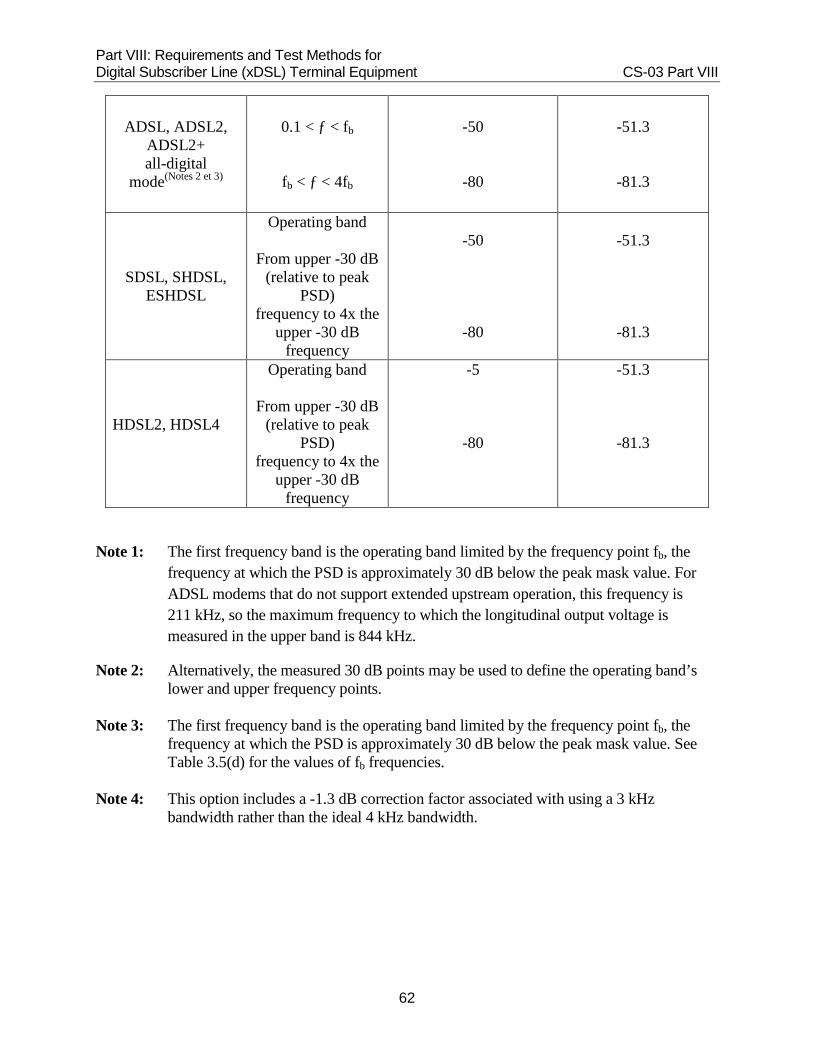
Table 3.5(c): Maximum Longitudinal Output Voltage (LOV) for Technologies Other Than VDSL2
Interface
Applicable Frequency
Range
Max. LOV (dBVrms) Averaged Over 1 s in All 4 kHz Frequency
Bands
Max. LOV (dBVrms)
Averaged Over 1 s in All 3 kHz
Frequency Bands4
ADSL, ADSL2, ADSL2+, RADSL2 over POTS(Notes 1 et 2
10 < ƒ < fb
fb < ƒ < 4fb
-50
-80
-51.3
-81.3
Part VIII: Requirements and Test Methods for Digital Subscriber Line (xDSL) Terminal Equipment CS-03 Part VIII
62
ADSL, ADSL2, ADSL2+ all-digital
mode(Notes 2 et 3)
0.1 < ƒ < fb
fb < ƒ < 4fb
-50
-80
-51.3
-81.3
SDSL, SHDSL, ESHDSL
Operating band
From upper -30 dB (relative to peak
PSD) frequency to 4x the
upper -30 dB frequency
-50
-80
-51.3
-81.3
HDSL2, HDSL4
Operating band
From upper -30 dB (relative to peak
PSD) frequency to 4x the
upper -30 dB frequency
-5
-80
-51.3
-81.3
Note 1: The first frequency band is the operating band limited by the frequency point fb, the frequency at which the PSD is approximately 30 dB below the peak mask value. For ADSL modems that do not support extended upstream operation, this frequency is 211 kHz, so the maximum frequency to which the longitudinal output voltage is measured in the upper band is 844 kHz.
Note 2: Alternatively, the measured 30 dB points may be used to define the operating band’s lower and upper frequency points.
Note 3: The first frequency band is the operating band limited by the frequency point fb, the
frequency at which the PSD is approximately 30 dB below the peak mask value. See Table 3.5(d) for the values of fb frequencies.
Note 4: This option includes a -1.3 dB correction factor associated with using a 3 kHz
bandwidth rather than the ideal 4 kHz bandwidth.

Part VIII: Requirements and Test Methods for Digital Subscriber Line (xDSL) Terminal Equipment CS-03 Part VIII
63
Table 3.5(d): Values of fb for Various All-Digital Mode Extended Upstream PSD Masks
Upstream Mask-Number
All-Digital Mode
Designator
fb (kHz )
fb (kHz) (With 48 dB/Octave Between f1 and f2)
1 ADLU - 32 184 213
2 ADLU - 36 207 239
3 ADLU - 40 230 266
4 ADLU - 44 253 293
5 ADLU - 48 276 319
6 ADLU - 52 299 346
7 ADLU - 56 322 372
8 ADLU - 60 345 399
9 ADLU - 64 368 426
Figure 3.5: Measurement Method for Longitudinal Voltage
Note 1: These resistors to be matched better than 0.1% tolerance.
Note 2: NT refers to network termination.

Part VIII: Requirements and Test Methods for Digital Subscriber Line (xDSL) Terminal Equipment CS-03 Part VIII
64
Annex A — Deployment Guidelines
To ensure spectral compatibility with other xDSL technologies deployed in the loop plant (i.e. to avoid third-party harm), ADSL, ADSL2, ADSL2+, HDSL2, SDSL, SHDSL, HDSL4, VDSL and VDSL2 systems should not be deployed on loops longer than the equivalent working length (EWL) identified below:
Table A1(a): Deployment Guidelines
xDSL Maximum EWL
ADSL All non-loaded loops
ADSL2, ADSL2+ See Table A1(b)
HDSL2 3200 m (10 500 ft)
2B1Q SDSL See Table A1(c)
SHDSL See Table A1(d)
HDSL4 All non-loaded loops
VDSL All non-loaded loops
VDSL2 All non-loaded loops
The EWL is defined as:
EWL = L26 + 0.75 (L24) + 0.60 (L22) + 0.40 (L19)
where:
L26 is the length of 26 AWG cable; L24 is the length of 24 AWG cable; L22 is the length of 22 AWG cable; and L19 is the length of 19 AWG or larger gauge cable in the assigned loop. Any xDSL transceiver using asymmetric spectra (ADSL, HDSL2, HDSL4) shall not be installed with a transceiver (TU-C) transmitting in the downstream frequency band (ADSL: 138-1,104 kHz; HSDL2: 0- 440 kHz; HDSL4: 0-600 kHz) located at the customer end of the loop (customer premises).
The administrative procedures to be used by local exchange carriers or other service providers to ensure that systems are installed on loops meeting these deployment guidelines are beyond the scope of this document.

Part VIII: Requirements and Test Methods for Digital Subscriber Line (xDSL) Terminal Equipment CS-03 Part VIII
65
Table A1(b): Deployment Guidelines for ADSL2 All-Digital Mode Range Extended Upstream
Mask Number
Upstream Mask Designator
ADSL Deployment Guideline, EWL
1 ADLU - 32 > 4725 m (15.5 kft)
2 ADLU - 36 3353 m (11.0 kft)
3 ADLU - 40 3201 m (10.5 kft)
4 ADLU - 44 3048 m (10.0 kft)
5 ADLU - 48 2896 m (9.5 kft)
6 ADLU - 52 2896 m (9.5 kft)
7 ADLU - 56 2744 m (9.0 kft)
8 ADLU - 60 2744 m (9.0 kft)
9 ADLU - 64 2744 m (9.0 kft)

Part VIII: Requirements and Test Methods for Digital Subscriber Line (xDSL) Terminal Equipment CS-03 Part VIII
66
Table A1(c): Deployment Guidelines for 2B1Q SDSL
PSD Maximum 2B1Q SDSL Line Bit Rate (kbps)
2B1Q SDSL Deployment Guideline,
EWL SM1 PSD mask 300 All non-loaded loops
SDSLu (f) with fsym = 160000 320 4725 m (15.5 kft)
SDSLu (f) with fsym = 168000 336 4420 m (14.5 kft)
SDSLu (f) with fsym = 192000 384 4115 m (13.5 kft)
SDSLu (f) with fsym = 200000 400 4115 m (13.5 kft)
SDSLu (f) with fsym = 208000 416 3965 m (13 kft)
SDSLu (f) with fsym = 232000 464 3810 m (12.5 kft)
SDSLu (f) with fsym = 264000 528 3660 m (12 kft)
SDSLu (f) with fsym = 296000 592 3505 m (11.5 kft)
SDSLu (f) with fsym = 328000 656 3355 m (11 kft)
SDSLu (f) with fsym = 360000 720 3200 m (10.5 kft)
SDSLu (f) with fsym = 392000 784 3050 m (10 kft)
SDSLu (f) with fsym = 456000 912 2895 m (9.5 kft)
SDSLu (f) with fsym = 488000 976 2745 m (9 kft)
SDSLu (f) with fsym = 552000 1104 2590 m (8.5 kft)
SDSLu (f) with fsym = 616000 1232 2440 m (8 kft)
SDSLu (f) with fsym = 712000 1424 2285 m (7.5 kft)
SDSLu (f) with fsym = 840000 1680 2135 m (7 kft)
SDSLu (f) with fsym = 936000 1872 1980 m (6.5 kft)
SDSLu (f) with fsym = 1064000 2128 1830 m (6 kft)
SDSLu (f) with fsym = 1128000 2256 1675 m (5.5 kft)
SDSLu (f) with fsym = 1160000 2320 1525 m (5 kft)

Part VIII: Requirements and Test Methods for Digital Subscriber Line (xDSL) Terminal Equipment CS-03 Part VIII
67
Table A1(d): Deployment Guidelines for SHDSL
SHDSL Line Bit Rate (LBR) (kbps)
SHDSL Deployment Guideline, EWL
LBR < 592 All non-loaded loops
600 < LBR < 616 4770 m (15.0 kft)
624 < LBR < 628 4420 m (14.5 kft)
656 < LBR < 688 4265 m (14.0 kft)
696 < LBR < 800 4115 m (13.5 kft)
808 < LBR < 832 3810 m (12.5 kft)
840 < LBR < 896 3660 m (12.0 kft)
904 < LBR < 952 3965 m (13.0 kft)
960 < LBR < 1000 3810 m (12.5 kft)
1008 < LBR < 1088 3660 m (12.0 kft)
1096 < LBR < 1160 3505 m (11.5 kft)
1168 < LBR < 1320 3355 m (11.0 kft)
1328 < LBR < 1472 3200 m (10.5 kft)
1480 < LBR < 1536 3050 m (10.0 kft)
1544 < LBR < 1552 3200 m (10.5 kft)
1560 < LBR < 1664 3050 m (10.0 kft)
1672 < LBR < 1880 2895 m (9.5 kft)
1888 < LBR < 2008 2745 m (9.0 kft)
2016 < LBR < 2320 2590 m (8.5 kft)
Part VIII: Requirements and Test Methods for Digital Subscriber Line (xDSL) Terminal Equipment CS-03 Part VIII
68
Annex B — Informative References
1. T1.417 - 2001: Spectrum Management for Loop Transmission Systems
2. ITU-T Recommendation K.50, G.992.3, G.992.5, G.993.2
3. T1 TRQ - XX: Technical Requirements for Maximum Voltage, Current and Power Levels for Network-Powered Transport Systems
4. CAN/CSA-C22.2 No. 60950-00: Safety of Information Technology Equipment 5. T1.424/Trial-Use - Interface Between Networks and Customer Installations—Very-high Speed
Digital Subscriber Lines (VDSL) Metallic Interface 6. T1E1.4/2002-002 - Draft proposed American National Standard, Spectrum Management for
Loop Transmission Systems, Issue 2