
Ontology-based Conceptual Design of ETL … Conceptual Design of ETL Processes for both Structured...
20
Ontology-based Conceptual Design of ETL Processes for both Structured and Semi-structured Data Dimitrios Skoutas National Technical University of Athens Athens, Hellas [email protected] Alkis Simitsis * National Technical University of Athens Athens, Hellas [email protected] ABSTRACT One of the main tasks in the early stages of a Data Warehouse project is the identification of the appropriate transformations and the specification of inter-schema mappings from the data sources to the Data Warehouse. In this paper, we propose an ontology-based approach to facilitate the conceptual design of the back stage of a Data Warehouse. A graph-based representation is used as a conceptual model for the datastores, so that both structured and semi-structured data are supported and handled in a uniform way. The proposed approach is based on the use of Semantic Web technologies to semantically annotate the data sources and the Data Ware- house, so that mappings between them can be inferred, thereby resolving the issue of heterogeneity. Specifi- cally, a suitable application ontology is created and used to annotate the datastores. The language used for de- scribing the ontology is OWL-DL. Based on the provided annotations, a DL reasoner is employed to infer se- mantic correspondences and conflicts among the datastores and propose a set of conceptual operations for transforming data from the source datastores to the Data Warehouse. 1. Introduction Successful planning and decision making in large enterprises requires the ability of efficiently processing and analyzing the organization’s informational assets, such as data regarding products, sales, customers, and so on. Such data is typically distributed in several heterogeneous sources and stored under different structures and formats. For this purpose, as well as performance issues, Data Warehouses are employed to integrate the data and provide an appropriate infrastructure for querying, reporting, mining and other advanced analysis tech- niques. One of the main challenges in the early phases of the design and deployment of a Data Warehouse is to identify the appropriate data sources and to specify the operations and transformations needed to overcome the arising structural and semantic conflicts. Specialized tools, commonly known as Extraction –Transformation – Loading (ETL) tools, have already been proposed to facilitate this procedure (Luján-Mora, Vassiliadis, & Trujillo, 2004; Trujillo & Lujan-Mora, 2003; Vassiliadis, Simitsis, & Skiadopoulos, 2002). Moreover, several commercial solutions already exist (IBM, 2005; Informatica, 2005; Microsoft, 2005; Oracle, 2005). However, the design part of these tools mainly focuses on the representation and modeling of the ETL proc- esses, whereas the identification of the required mappings and transformations needs to be done manually. The lack of precise metadata hinders the automation of this task. The required information regarding the semantics of the data sources, as well as the constraints and requirements of the Data Warehouse application, tends to be missing. Usually, such information is incomplete or even inconsistent, often being hard-coded within the sche- mata or metadata of the sources or even provided in natural language format after oral communication with the involved parties; e.g., business managers and administrators/designers of the Data Warehouse (Hüsemann, Lechtenbörger, & Vossen, 2000). As a result, designing ETL processes becomes a very tedious and error-prone task. Given the fact that typical ETL processes are quite complex and that significant operational problems can occur with improperly designed ETL systems, developing a formal, metadata-driven approach to allow a high degree of automation of the ETL design, is critical in employing a Data Warehouse solution. The schema of a datastore describes the way that data is structured when stored, but does not provide any in- formation for its intended semantics. Therefore, metadata are required to allow for the understanding, manage- * Work performed at Dept. of Electrical and Computer Engineering, NTUA. Current address: IBM Almaden Research Cen- ter, San Jose, CA 95120, USA – [email protected].
-
Upload
truongminh -
Category
Documents
-
view
219 -
download
0
Transcript of Ontology-based Conceptual Design of ETL … Conceptual Design of ETL Processes for both Structured...

Ontology-based Conceptual Design of ETL Processes for both Structured and Semi-structured Data
Dimitrios Skoutas
National Technical University of Athens Athens, Hellas
Alkis Simitsis* National Technical University of Athens
Athens, Hellas [email protected]
ABSTRACT
One of the main tasks in the early stages of a Data Warehouse project is the identification of the appropriate transformations and the specification of inter-schema mappings from the data sources to the Data Warehouse. In this paper, we propose an ontology-based approach to facilitate the conceptual design of the back stage of a Data Warehouse. A graph-based representation is used as a conceptual model for the datastores, so that both structured and semi-structured data are supported and handled in a uniform way. The proposed approach is based on the use of Semantic Web technologies to semantically annotate the data sources and the Data Ware-house, so that mappings between them can be inferred, thereby resolving the issue of heterogeneity. Specifi-cally, a suitable application ontology is created and used to annotate the datastores. The language used for de-scribing the ontology is OWL-DL. Based on the provided annotations, a DL reasoner is employed to infer se-mantic correspondences and conflicts among the datastores and propose a set of conceptual operations for transforming data from the source datastores to the Data Warehouse.
1. Introduction
Successful planning and decision making in large enterprises requires the ability of efficiently processing and analyzing the organization’s informational assets, such as data regarding products, sales, customers, and so on. Such data is typically distributed in several heterogeneous sources and stored under different structures and formats. For this purpose, as well as performance issues, Data Warehouses are employed to integrate the data and provide an appropriate infrastructure for querying, reporting, mining and other advanced analysis tech-niques. One of the main challenges in the early phases of the design and deployment of a Data Warehouse is to identify the appropriate data sources and to specify the operations and transformations needed to overcome the arising structural and semantic conflicts. Specialized tools, commonly known as Extraction –Transformation – Loading (ETL) tools, have already been proposed to facilitate this procedure (Luján-Mora, Vassiliadis, & Trujillo, 2004; Trujillo & Lujan-Mora, 2003; Vassiliadis, Simitsis, & Skiadopoulos, 2002). Moreover, several commercial solutions already exist (IBM, 2005; Informatica, 2005; Microsoft, 2005; Oracle, 2005).
However, the design part of these tools mainly focuses on the representation and modeling of the ETL proc-esses, whereas the identification of the required mappings and transformations needs to be done manually. The lack of precise metadata hinders the automation of this task. The required information regarding the semantics of the data sources, as well as the constraints and requirements of the Data Warehouse application, tends to be missing. Usually, such information is incomplete or even inconsistent, often being hard-coded within the sche-mata or metadata of the sources or even provided in natural language format after oral communication with the involved parties; e.g., business managers and administrators/designers of the Data Warehouse (Hüsemann, Lechtenbörger, & Vossen, 2000). As a result, designing ETL processes becomes a very tedious and error-prone task. Given the fact that typical ETL processes are quite complex and that significant operational problems can occur with improperly designed ETL systems, developing a formal, metadata-driven approach to allow a high degree of automation of the ETL design, is critical in employing a Data Warehouse solution.
The schema of a datastore describes the way that data is structured when stored, but does not provide any in-formation for its intended semantics. Therefore, metadata are required to allow for the understanding, manage-
* Work performed at Dept. of Electrical and Computer Engineering, NTUA. Current address: IBM Almaden Research Cen-ter, San Jose, CA 95120, USA – [email protected].

~ 2 ~
ment and processing of this data. Semantic Web technologies provide a means to formally specify the meta-data, so that automated reasoning techniques can be employed to facilitate further processing. The Semantic Web is an extension of the current Web, where information is described by formally defined, machine-processable metadata to further facilitate and automate tasks such as searching, sharing and combining informa-tion. Ontologies are a key enabling technology for the Semantic Web. Borst (1997) defines an ontology as a formal and explicit specification of a shared conceptualization. An ontology provides a way for describing the meaning and relationships of the terms in a domain. In the context of a Data Warehouse application, ontologies can be used as a conceptual model for describing the semantics of the data sources, allowing reasoning tech-niques to be applied for inferring correspondences or conflicts among these sources.
Earlier work argues that ontologies constitute a very suitable model for describing the semantics of the data sources in a Data Warehouse application and automatically identifying correspondences among these sources (Skoutas & Simitsis, 2006). Specifically, integration from relational sources is considered. The designer uses the application requirements, as well as implicit knowledge of the domain, to create a shared vocabulary, i.e. a set of terms, and applies this vocabulary to annotate the tables and attributes of each source, such as denoting whether null values are allowed for an attribute or what unit of measurement is used for the values of an attrib-ute. Given the vocabulary and the annotations, an ontology is constructed, based on which reasoning tasks may be performed to facilitate the ETL workflow construction.
On the other hand, even though the relational model has widespread adoption and an RDBMS constitutes the typical solution for storing an organization’s operational data, due to the increasingly important role of the Internet and the World Wide Web in e-commerce and business transactions in general, semi-structured data play also a progressively more important role in this context, significantly increasing the amount of heterogene-ity between the data sources, and thus, the complexity of the ETL design process. Semi-structured data refers to data that is neither raw data (e.g., images, sound) nor explicitly structured (e.g., data in a relational database) (Abiteboul, 1997; Buneman, 1997), and are typically handled by means of wrappers and mediators (Garcia-Molina et al., 1997; Papadakis et al., 2005). Moreover, the emergence of XML, as a standard for allowing in-teroperability, requires that data crossing the borders of the organization is structured in XML format, while Web Services enable enterprises to cooperate by forming dynamic coalitions, knows as Virtual Organizations. Such environments raise new challenges for the problem of data integration, since naming conventions or cus-tom-defined metadata which may be sufficient for integration within a single organization, are of little use when integrating inter-organization information sources.
In this paper, we further extend and elaborate on previous work. Specifically, we address two main issues. First, we extend the results of previous work that considers only relational datastores or datastores exposing a relational schema (Skoutas & Simitsis, 2006). With the increased importance of the Web as an information repository and the widespread adoption of XML, the need for incorporating semi-structured data in Data Ware-house can not be overlooked. Both structured and semi-structured data need to be addressed in a uniform way, facing a higher degree of heterogeneity. Second, the creation of the application ontology and the annotation of the datastores still constitute a time-consuming effort needed to be done by the designer. It is important to fa-cilitate this process so as to further lighten the burden of the designer.
Contributions. In particular, the following contributions of the current work are employed to address the above issues:
A graph-based representation, called datastore graph, is employed as a common model for the datas-tores. Graphs constitute a generic data model allowing the representation of several types of schemas, including relational and XML schemas, thereby allowing for both structured and semi-structured sources to be handled in a unified way.
A graph representation, termed ontology graph, is introduced for the application ontology. Providing a visual, graph-based representation, with different symbols for the different types of classes and proper-ties in the ontology, makes it easier for the designer to create, verify and maintain the ontology, as well as use it as a means of communication between different parties involved in the project.

~ 3 ~
Annotation of a datastore is accomplished by formally defining mappings between the nodes of the datastore graph and the ontology graph. These mappings can be represented as labels assigned to the nodes of the data store graph, i.e. the datastore is semantically described by the annotated datastore graph. The mappings may be specified visually – e.g., by implementing drag-and-drop functionality be-tween the visual representations of the corresponding graphs – significantly decreasing the time and ef-fort required for establishing and maintaining the mappings.
Based on the application ontology and the annotated datastore graphs, automated reasoning techniques are used to infer correspondences and conflicts among the datastores, thus identifying relevant sources and proposing conceptual operations for integrating data into the Data Warehouse.
Outline. The rest of the paper is organized as follows. Section 2 discusses the related work. Section 3 describes the graph-based representation of the datastores. Section 4 presents the construction of a suitable ontology to model the application domain and requirements, as well as its corresponding graph representation. Section 5 describes the semantic annotation of the datastores, by mapping the datastore graphs to the ontology graph. Section 6 discusses the use of the semantic annotation of the datastores to infer correspondences and conflicts among the datastores and propose a set of conceptual operations for transforming data from a source to a target store. Section 7 discusses implementation issues, while section 8 concludes the paper.
2. Related Work
This section presents the state of the art concerning the conceptual design of ETL process, as well as the prob-lem of data integration from heterogeneous sources in general.
Conceptual models for ETL and DW’s. Previous work concerning the automatic derivation of ETL transfor-mations and inter-attribute mappings in the early stages of a Data Warehouse project considers only relational datastores or datastores exposing a relational schema (Skoutas & Simitsis, 2006). Furthemore, there exist sev-eral approaches that deal with the conceptual part of the design of an ETL scenario (Kimball & Caserta, 2004; Kimball et al., 1998; Luján-Mora et al., 2004; Trujillo & Lujan-Mora, 2003; Vassiliadis et al., 2002). However, these approaches are only concerned with the graphical design and representation of ETL processes. Existing commercial tools facilitate the design of ETL workflows without providing any mechanism for the automatic identification of the appropriate transformations based on the semantics of the datastores involved (IBM, 2005; Informatica, 2005; Microsoft, 2005; Oracle, 2005).
On the other hand, there exist some approaches concerning the (semi-) automation of several tasks of logical Data Warehouse design from conceptual models, but they do not provide a formal method to specifically de-termine the flow of data from the source recordsets towards the Data Warehouse. A couple of approaches con-cern the development of dimensional models from traditional ER-models (Ballard, 1998; Moody & Kortink, 2000). In other approaches the Data Warehouse logical schema is generated from a conceptual schema. Peralta (2003) presents a framework for generating a Data Warehouse logical schema from a conceptual schema. Boehnlein and Ulbrich-vom Ende (1999) describe an approach to derive initial Data Warehouse structures from the conceptual schemes of operational sources. Hüsemann, Lechtenbörger, and Vossen (2000) propose an ap-proach for the derivation of a Data Warehouse schema from the conceptual schema of an operational database. Golfarelli and Rizzi (1998) propose a general methodological framework for Data Warehouse design, based on Dimensional Fact Model. Hahn, Sapia, and Blaschka (2000) present a modeling framework, BabelFish, con-cerning the automatic generation of OLAP schemata from conceptual graphical models and discuss the issues of this automatic generation process for both the OLAP database schema and the front-end configuration. Phipps and Davis (2002) propose algorithms for the automatic design of Data Warehouse conceptual schemata. An approach for Data Warehouse development based on the Model Driven Architecture is presented by Mazon et al. (2005). Finally, the conceptual design of a Data Warehouse from XML sources has been addressed by Golfarelli, Rizzi, and Vrdoljak (2001), which discuss the increased importance of XML data for modern or-ganizations, and consequently the need to incorporate XML data in Data Warehouses, as well as the main is-sues arising from the fact that XML is used to model semi-structured data. The Dimensional Fact Model is adopted as the conceptual model for the Data Warehouse and a semi-automatic approach for the conceptual
~ 4 ~
design from XML sources is presented, emphasizing on the different ways of representing relationships in DTDs and XML Schemas.
Data integration. In a different line of research, the problem of data integration from heterogeneous sources, defined as providing the user with a unified view of data residing at different sources, has been extensively investigated in the literature (Calì et al., 2004; Lenzerini, 2002; Halevy, 2001). The typical architecture of a data integration system comprises a set of data sources, containing the actual data, and a global schema, provid-ing an integrated view over these underlying sources. The main approaches for modeling the relation between the sources and the global schema are “global-as-view”, where the global schema is expressed in terms of the data sources, and “local-as-view”, where the global schema is defined independently and each source is de-scribed as a view over it. One of the main tasks in the design of a data integration system is to establish the mappings between the sources and the global schema.
The use of Description Logics in data integration systems has also been studied in the literature. The problem of rewriting queries using views in Description Logics has been investigated by Beeri, Halevy, and Rousset (1997), as well as Calvanese, De Giacomo, and Lenzerini (1999). The SIMS project addresses the issue of inte-grating heterogeneous sources, by using a shared ontology to establish a fixed vocabulary for describing the data sets in the domain (Arens, Knoblock, & Shen, 1996). Queries are expressed in domain terms and are re-formulated into queries to specific information sources. Catarci and Lenzerini (1993) have presented a formal framework for representing inter-schema knowledge in cooperative information systems. Another approach towards data integration and reconciliation in a Data Warehouse environment is based on a conceptual repre-sentation of the application domain (Calvanese, De Giacomo, & Rosati, 1999). The approach follows the local-as-view paradigm, relying on a declarative description of the data sources in terms of the enterprise conceptual model, which is expressed in an Entity-Relationship formalism.
A problem similar to data integration is that of data exchange, defined as the problem of transforming data structured under one schema into data structured under another schema. The fundamental theoretical issues concerning data exchange have been investigated in the literature (Fagin et al., 2005; Fagin, Kolaitis, & Popa, 2005; Kolaitis, Panttaja, & Tan, 2006; Libkin, 2006). Data exchange between XML schemas has also been studied (Arenas & Libkin, 2005; Popa et al., 2002).
Integration of XML data has also been studied. Rodríguez-Gianolli and Mylopoulos (2001) proposed a system that applies a set of heuristic rules to semi-automatically integrate XML documents into a common conceptual schema. Bianchini and De Antonellis (2004) described a methodology for semi-automatically constructing an ontology from a set of heterogeneous XML data sources allowing users to formulate queries at the conceptual level.
Our approach follows the “local-as-view” paradigm, where the application ontology, constructed as a concep-tual model of the domain, corresponds to the global schema, and the semantic descriptions of the datastores, in terms of classes and properties defined in the ontology, correspond to the views describing the local schemata. However, the use of an OWL ontology, instead of a global schema provides a formal model on which auto-mated reasoning mechanisms may be applied. Furthermore, in contrast to the approaches described above, we do not address the problem as a query rewriting problem, since the transformations taking place in a real-case ETL scenario usually include operations, such as the application of functions, that can not be captured by a query rewriting process.
3. Graph-Based Representation for the Datastores
In this section, we describe a method for the representation of datastores as graphs. Using graphs as a common model to represent the datastore schemata, possibly exposed by means of appropriate wrappers, allows for both structured and semi-structured datastores to be handled in a uniform way.
Preliminaries. A graph is a pair G=(V,E) of sets, with V∩E=Ø, where V is a finite, non-empty set of nodes and E⊆V×V is a set of edges. If the edges are ordered pairs of nodes, then G is called a directed graph. Two nodes

~ 5 ~
v1,v2∈V of G are called adjacent if (v1,v2)∈E. A node v is incident with an edge e if v∈e. The set of all edges with which v is incident, is denoted by E(v). The number of edges at v, i.e. |E(v)|, is called the degree of node v, denoted by d(v). In the case of directed graphs, d+(v) denotes the in-degree of node v, i.e. the number of incoming edges at v, while d-(v) denotes the out-degree of v, i.e. the number of outgoing edges at v. A node v will be called internal node if d-(v)>0, otherwise it will be called a leaf node. Moreover, it is possible to assign labels to the nodes and/or the edges of a graph. A labeled graph can be defined as follows:
G=(ΣV,ΣE,V,E,lV,lE)
where ΣV, ΣE, V, E, lV, lE are, respectively, finite alphabets of the available node and edge labels, the sets of nodes and edges, and two maps describing the labeling of the nodes and edges.
Datastore graph. The schema SD of a datastore can be viewed as consisting of a set of elements, which can be distinguished in two types: (a) elements that contain the actual data, and (b) elements that contain or refer to other elements, creating the structure of the schema. In this sense, the schema can be depicted by a directed graph, with nodes corresponding to the elements of the schema and edges representing containment or refer-ence of one element by another. Additionally, labels may be assigned to edges denoting the corresponding car-dinality. Therefore, we consider a graph, termed Datastore Graph, representing a datastore schema as an edge-labeled directed graph GD=(VD, ED, lE) such that:
Each element e defined in the schema SD is represented by a node ve∈VD.
Each containment relationship is represented by an edge (v1,v2), where v2 corresponds to the element being contained by the element represented by v1.
Each reference is represented by an edge (v1,v2), where v1 corresponds to the element containing the reference and v2 corresponds to the referenced element.
Each edge is assigned a label of the form [min,max], where min and max denote, respectively, the minimum and maximum cardinality of the reference or containment relationship represented by the edge.
Elements containing the actual data are represented by leaf nodes. A graph-based representation may be de-rived for any schema type, based on the above specification. In the cases that no schema is explicitly exposed by a datastore, an appropriate wrapper needs to be constructed first, to provide an interface for retrieving the relevant data based on the underlying structure.
Given that the relational schema and XML constitute the most typical models for structured and semi-structured data, respectively, in the following, we elaborate on the construction of the graph representation for these two cases.
Relational schema to graph. A relational schema SR consists of a set of relations R, each one comprising a set of attributes AR. The relational schema can be depicted by a directed graph GR=(VR,ER), where the nodes VR correspond to the set of relations and the (non foreign key) attributes of the schema, while the edges ER repre-sent the containment of attributes in relations, as well as references between relations, i.e. foreign keys. Addi-tionally, for representing cardinality constraints, labels of the form [min,max] may be assigned to the edges of the graph (with null denoting that no constraint is specified). Thus GR is essentially an edge-labeled graph GR=(VR,ER, lEr).
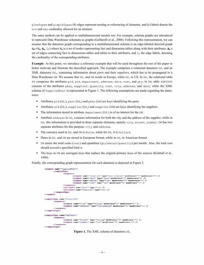
XML schema to graph. XML is the most commonly used format for the exchange of semi-structured data (Abiteboul, Suciu, & Buneman, 2000). An XML document consists of nested element structures, starting with a root element. Each element may contain other elements and/or attributes. Often a DTD or an XML Schema is associated to the XML document, defining a set of constraints to which the XML document should conform in order to be considered valid. An XML Schema consists of element declarations and type definitions. Relation-ships between entities are represented by nesting elements or by references. The constraints minOccurs and maxOccurs are provided to restrict the cardinality of an element. Thus, an XML Schema SX may be repre-sented by a directed edge-labeled graph GX=(VX,EX, lEx), where (a) nodes represent elements, attributes, com-
~ 6 ~
plexTypes and simpleTypes (b) edges represent nesting or referencing of elements, and (c) labels denote the min and max cardinality allowed for an element.
The same method can be applied to multidimensional models too. For example, schema graphs are introduced to represent Data Warehouse schemata as graphs (Golfarelli et al., 2006). Following this representation, we can assume that the datastore graph corresponding to a multidimensional schema is an edge-labeled directed graph GM=(VM, EM, lE) where VM is a set of nodes representing fact and dimension tables along with their attributes, EM a set of edges connecting fact to dimensions tables and tables to their attributes, and lE the edge labels, denoting the cardinality of the corresponding attributes.
Example. At this point, we introduce a reference example that will be used throughout the rest of the paper to better motivate and illustrate the described approach. The example comprises a relational datastore DS1 and an XML datastore DS2, containing information about parts and their suppliers, which has to be propagated to a Data Warehouse DW. We assume that DS1 and DW reside in Europe, while DS2 in US. In DS1 the relational table PS comprises the attributes pid, sid, department, address, date, cost, and qty; in DW, table PARTSUP consists of the attributes pkey, supplier, quantity, cost, city, address, and date; while the XML schema of SuppliedPart is represented in Figure 1. The following assumptions are made regarding the datas-tores:
Attributes pid (DS1), part (DS2) and pkey (DW) are keys identifying the parts.
Attributes sid (DS1), supplier (DS2) and supplier (DW) are keys identifying the suppliers.
The information stored in attribute department (DS1) is of no interest for the DW.
Attribute address in DS1 contains information for both the city and the address of the supplier, while in DS2 this information is provided in three separate elements, namely city, street, number. DW has two separate attributes for this purpose: city and address.
The currency used in DS1 and DW is Euros, while for DS2 it is Dollars.
Dates in DS1 and DW are stored in European format, while in DS2 in American format.
DW stores the total costs (cost) and quantities (qty/amount/quantity) per month. Also, the total cost should exceed a specified limit N.
The keys in DW are surrogate keys that replace the original primary keys of the sources (Kimball et al., 1998).
Finally, the corresponding graph representation for each datastore is depicted in Figure 2.
Figure 1. The XML schema of datastore DS2

~ 7 ~
(a)
(c)
(b) Figure 2. Datastore graphs for (a) DS1, (b) DS2, and (c) DW
Notation Name Description
C Class A class is a group of individuals sharing some properties. Classes represent the concepts of the domain being modeled, as well as types of values of their attributes.
C1 ≡ C2 equivalent Used to state that two classes are equivalent, i.e. each instance of the one class is also an in-stance of the other.
C1 ⊑ C2 subClassOf Used to create class hierarchies, by stating that a class C1 is a subclass of or is subsumed by another class C2.
C1 ⊓ C2 = ∅ disjointWith States that two classes C1 and C2 are disjoint, i.e. an individual may not belong to both C1 and C2. This feature is used to prevent the integration of data records from sources with conflicting constraints.
C1 ⊔ C2 unionOf Denotes the union of two classes.
C1 ⊓ C2 intersectionOf Denotes the intersection of two classes.
P Property Relates an instance of a class to an instance of another class (ObjectProperty). Properties areused in our model for representing attributes of concepts and relationships between concepts.
dom(P) domain Specifies the class(-es) to which the individuals the property applies to, belong. rang(P) range Specifies the class(-es) to which the individuals being the values of the property, belong.
∀P.C allValuesFrom Used to restrict the range of a property, when this property is applied to individuals of a spe-cific class.
≥nP, ≤nP min/max cardinality
Specifies the min/max cardinality of a property in respect to a specific class. We use this fea-ture to denote the cardinality of attributes and relationships.
Table 1. OWL features used in our approach
4. Ontology Construction
In this section, we describe the process for constructing a suitable application ontology to semantically annotate the datastores. This ontology should provide the ability to describe the semantics of the datastore schemas, so that data transformation and integration can be accomplished with a high degree of automation, based on the use of automated reasoning. The Web Ontology Language (OWL) is chosen as the language for representing the ontology (Smith, Welty, & McGuinness, 2004). OWL, and in particular OWL-DL, is based on Description Logics, a decidable fragment of First Order Logic, constituting the most important and commonly used knowl-edge representation formalism (Baader et al., 2003). Therefore, it provides a formal and explicit representation, allowing existing reasoners to be used for automating several tasks of the process, such as checking subsump-tion relationships between classes. In our approach, only a subset of the features provided by the language is required. These features are summarized in Table 1. Specifically, for the ontology creation process it is only needed to create a set of classes and properties, to specify the domain and range of each property, and to organ-ize the classes in an appropriate hierarchy. Therefore, given that several tools exist providing an intuitive and comprehensive Graphical User Interface for the development of ontologies, this task requires only a basic un-derstanding of ontologies and OWL. On the other hand, a precise understanding of the intended semantics of

~ 8 ~
the datastore schemata, and generally the application requirements, is critical in constructing an appropriate ontology and correctly annotating the datastores.
For our purpose, a suitable application ontology should provide the ability for modeling the following types of information: (a) the concepts of the domain, (b) the relationships between those concepts, (c) the attributes characterizing each concept, and (d) the different representation formats and (ranges of) values for each attrib-ute. The concepts of the domain are represented by classes, while the relationships between concepts, as well as the attributes of the concepts are represented by properties. The different types of values for each attribute are also represented by classes appropriately organized in a hierarchy. Due to the significance of aggregate opera-tions in a Data Warehouse setting, specific elements are included in the ontology, so as to explicitly specify such operations.
Formally, the constructed ontology can be modeled as O=(C,P,A) comprising the following:
C = CC ∪ CT ∪ CG
P = PP ∪ {convertsTo, aggregates, groups}
A, a set of axioms used to (a) assert subsumption relationships between classes, (b) specify domain and range constraints on properties, (c) specify cardinality constraints, (d) assert disjointness of classes, and (e) define a new class in terms of other classes and properties.
The above notations are explained in more detail in the following. CC is a set of classes representing the con-cepts of the domain. CG is a set of classes describing aggregate operations. Each class in CG denotes an aggre-gate function, e.g., AVG, SUM, COUNT, MAX. PP is a set of properties representing attributes of the concepts or relationships between them.
For each property p∈PP, an axiom exists in A specifying a class c∈CC as the domain of p, thus, associating the property with the concept it describes. If p relates a concept to another concept, represented by class c΄∈CC, then c΄ is specified as the range of p. CT is the union of a set of classes, CT=CTP∪CTF∪CTR∪CTG, used to represent different kinds of values for a property that corresponds to an attribute of a concept. For each such property p, a class in CTP is declared to be the range of this property. That is, this class represents all the possible (types of) values for this property. Every other class in CT denoting a specific type of values of p is a subclass of this class. CTF refers to the set of classes used to denote different representation formats, while CTR to the set of classes denoting different (ranges of) values for a property. Classes in CTG represent values that result from ag-gregate operations. The classes in CT are organized in an appropriate hierarchy according to the intended se-mantics. For instance, if a value interval, represented by class cr∈CTR, refers to a particular representation for-mat, represented by class cf∈CTF, then cr is asserted to be a subclass of cf. If two types of values are mutually exclusive, then an axiom exists in A stating that the corresponding classes are disjoint.
Property convertsTo is used to relate a class c1∈CTF to another class c2∈CTF, indicating that a function exists for transforming data from the representation format represented by c1 to the representation format represented by c2. Property aggregates is used to relate a class c1∈CG to another class c2∈CTG, indicating that the aggre-gate function represented by c1 is used to calculate the values represented by c2. Finally, property groups re-lates a class c1∈CTG to another class c2∈CT, indicating that the aggregate operation for calculating the values represented by c1 is applied over the values represented by c2.
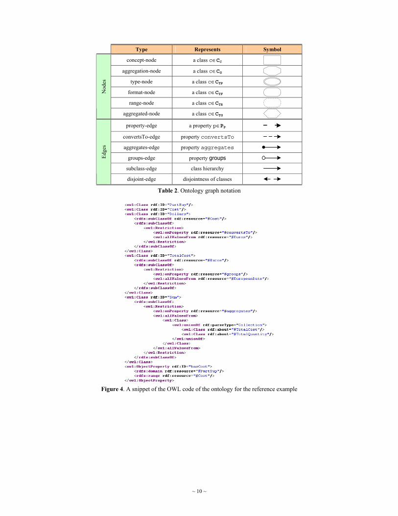
Ontology graph. After the ontology has been created by the designer, a corresponding graph representation, called Ontology Graph, is derived. The ontology graph is a directed edge-labeled graph GO=(VO,EO, lE), where nodes represent classes in the ontology, while edges represent properties. Table 2 depicts the different types of nodes and edges in the ontology graph and their corresponding visual notation.
Formally, the construction of the ontology graph is described by the algorithm O2G depicted in Figure 3. The algorithm iterates over the properties defined in the ontology, and creates: (a) one concept-node for each class appearing in the domain of a property, (b) one type-node for each class appearing in the range of a property, and (c) a property-edge connecting the concept-node with the type-node. For each convertsTo restriction, a

~ 9 ~
format-node is created and a convertsTo-edge is added between the node having the restriction and the format-node. Similarly, the same procedure is repeated for restrictions aggregates and groups. Finally, subclass-edges and disjoint-edges are created according to subsumption and disjointness of classes, respectively.
Algorithm Ontology to Graph (O2G)
Input: The application ontology O Output: The ontology graph GO=(VO,EO, lE) 1. Begin 2. Foreach property p in PP { 3. c1 the class being the domain of p; 4. c2 the class being the range of p; 5. If ( n(c1)∉VO ) { create concept-node n(c1); } 6. If ( n(c2)∉VO ) {
7. If ( ∃p΄:c2 ⊑ domain(p΄)) 8. { create concept-node n(c2); } 9. Else 10. { create type-node n(c2); } 11. } 12. create property-edge (n(c1),n(c2)) with label p; 13. } 14. Foreach range restriction on property convertsTo { 15. c1 the class having the restriction; 16. c2 the class being the filler of the restriction; 17. If ( n(c1)∉VO ) { create format-node n(c1); } 18. If ( n(c2)∉VO ) { create format-node n(c2); } 19. create convertsTo-edge (n(c1),n(c2)); 20. } 21. Foreach range restriction on property aggregates { 22. c1 the class having the restriction; 23. c2 the class being the filler of the restriction; 24. If ( n(c1)∉VO ) { create aggregation-node n(c1); } 25. create aggregated-node n(c2); 26. create aggregates-edge (n(c1),n(c2)); 27. } 28. Foreach range restriction on property groups { 29. c1 the class having the restriction; 30. c2 the class being the filler of the restriction; 31. create groups-edge (n(c1),n(c2)); 32. } 33. Foreach subclass relation: c1 ⊑ c2 { 34. If ( n(c1)∉VO ) { create range-node n(c1); } 35. If ( n(c1)∉VO ) { create range-node n(c2); } 36. create subclass-edge (n(c2),n(c1)); 37. } 38. Foreach disjointness axiom: c1 ⊓ c2 = Ø { 39. create disjoint-edge (n(c1),n(c2)); 40. create disjoint-edge (n(c2),n(c1)); 41. } 42. End.
Figure 3. Algorithm for graph representation of the ontology
~ 10 ~
Type Represents Symbol
concept-node a class c∈CC aggregation-node a class c∈CG
type-node a class c∈CTP format-node a class c∈CTF range-node a class c∈CTR
Nod
es
aggregated-node a class c∈CTG property-edge a property p∈PP
convertsTo-edge property convertsTo aggregates-edge property aggregates
groups-edge property groups subclass-edge class hierarchy
Edge
s
disjoint-edge disjointness of classes Table 2. Ontology graph notation
Figure 4. A snippet of the OWL code of the ontology for the reference example

~ 11 ~
Figure 5. Graph representation of the created ontology
Example. Consider the reference example presented before. The application domain comprises the concept PartSup, with properties part, supplier, city, address, date, quantity and cost. For each of these properties, a corresponding property is created in the ontology, as well as a generic class to denote its values. The following may be derived from the assumptions made in the example. There is a need to distinguish be-tween keys used in the data sources and surrogate keys used in the Data Warehouse. For this reason, e.g., for part id’s, two different classes SourcePid and SurrogatePid are introduced in the ontology, related via the property convertsTo. In the case of cost, the classes Dollars and Euros are used to represent values refer-ring to these two different currencies. Similarly, for the property date, the classes AmericanDate and Euro-peanDate are introduced to represent different date formats. Again, the property convertsTo is used to indi-cate the ability to convert from one currency or date format to the other. The classes TotalCost and Total-Quantity are introduced to represent aggregated costs and quantities. Notice that these classes are associated to the classes Sum and EuropeanDate to explicitly denote, respectively, the aggregation function and attribute. Finally class AboveN denotes total costs exceeding the specified limit of N euros. Figure 4 presents a snippet of the OWL code of this ontology. The ontology graph, generated by applying algorithm O2G, is illustrated in Figure 5.

DS1 mappings DS2 mappings DW mappings
(PS, PartSup) (pid, SourcePid) (sid, SourceSid) (department, -) (address, City)
(address, Address) (date, EuropeanDate)
(cost, Euros) (qty, Quantity)
(SuppliedPart, PartSup) (part, SourcePid)
(supplier, SourceSid) (location, -) (city, City) (address, -)
(street, Address) (number, Address)
(date, AmericanDate) (amount, Quantity) (cost, Dollars)
(PARTSUP, PartSup) (pkey, SurrogatePid)
(supplier, SurrogateSid) (quantity, TotalQuantity)
(cost, AboveN) (city, City)
(address, Address) (date, EuropeanDate)
Table 3. Mappings for the datastores DS1, DS2 and DW
5. Mapping and Annotation
In this section, we introduce a method for the semantic annotation of the datastores, by mapping the datastore schemata involved in an ETL scenario to the application ontology. Based on these mappings, a set of defined classes representing the datastores is generated and added to the ontology. This procedure reveals the semantics of the elements contained in the datastore schemata, allowing a reasoning process to be applied for identifying necessary operations towards the population of the Data Warehouse.
The annotation of each datastore is accomplished by defining mappings between the datastore graph GS and the ontology graph GO. These mappings are specified by the designer and are pairs of the form (vS,vO), where vS and vO denote nodes of GS and GO, respectively. Specifically, each internal node of GS may be mapped to one concept-node of GO. It is not required for all internal nodes to be mapped, since some of these nodes exist for structural purposes and do not represent a concept of the domain being modeled. A leaf node of GS may be mapped to one or more nodes of GO of the following types: type-node, format-node, range-node or aggregated-node. In this way, the elements of the datastore schema containing the actual data are semantically annotated, e.g., specifying the representation format or value ranges, for the underlying data. It is possible to specify more than one mappings for a leaf node, e.g., in the case that the datastore allows for more than one representation format to be used for the values of the corresponding property. If no mapping is specified for a leaf node, it means that the corresponding attribute is of no interest for the specific application and does not participate in the integration process, i.e. the node is ignored from any further process.
Note that an additional advantage of using a graph-based representation for both the datastores and ontology is the fact that graphical tools can be developed to allow for a visual representation and specification of these mappings, e.g., by using a “drag-and-drop” technique between graph nodes to create a mapping, thus facilitat-ing and speeding up the mapping process. Furthermore, it is possible to incorporate schema matching tech-niques to automatically detect candidate mappings (Rahm & Bernstein, 2001). The specified mappings can be represented as labels assigned to the nodes of the source graph for which a mapping is specified.
Example. The appropriate mappings for the datastores of the reference example are presented in Table 3.
After the appropriate mappings between the datastore graphs and the ontology graph have been considered, a set of definitions are created to semantically describe each datastore. In particular, for each labeled internal node n of the datastore graph, a defined class c(n) is created and added to the ontology. The label of node n is then updated to indicate this defined class. The class c(n) is a subclass of the class indicated by the label of node n, containing also a set of restrictions derived from the specified mappings of the neighbor labeled nodes of n. A neighbor labeled node of n is each node n΄ for which the following conditions hold:
n΄ is labeled; i.e. it is mapped to one or more nodes of the ontology graph,
there is a path p in the source graph from mode n to node n΄, and
p contains no other labeled nodes, except n and n΄.

~ 13 ~
Algorithm Create the Definition for an Internal labeled node (CDI)
Input: An internal labeled node n of the datastore graph GS and the applica-tion ontology O
Output: A defined class c(n) representing node n 1. Begin 2. If ( c(n)∉O ) { create class c(n); } 3. nO(cO) the ontology graph node indicated by the label of n; 4. set c(n) subclass of cO: c(n)⊑ cO; 5. Foreach neighbor labeled node n΄ of n { 6. min, max cardinalities for path(n,n΄); 7. Foreach label of n΄ { 8. c΄ the class indicated by the label; 9. p the property relating class cO to c΄ or to any superclass of c΄; 10. If ( min≠null ) 11. { c(n) add min cardinality restriction: ≥min p; } 12. If ( max≠null ) 13. { c(n) add max cardinality restriction: ≤max p; } 14. If ( n΄ is internal node ) { 15. If ( c(n΄)∉O ) { create class c(n΄); }
16. c(n) add restriction: ∀p.c(n΄); 17. } 18. Else 19. { c(n) add restriction: ∀p.c΄; } 20. } 21. } 22. End.
Figure 6. Algorithm for creating the definition for an internal labeled node of the datastore graph
The intuition for using the notion of neighbor labeled nodes lies in the fact that nodes without associated map-pings are of no interest, and therefore need to be ignored. Thus, each labeled internal node is linked to a set of other, internal or leaf, labeled nodes. The cardinality for each one of these links is computed by multiplying the corresponding cardinalities along the path connecting the two nodes. Note that if the min (max) cardinality of an edge in the path equals to null, then the final min (max) cardinality is also null. The process for deriving the defined class c(n) for an internal labeled node n is formally specified by the algorithm CDI shown in Figure 6.
Example. The defined classes derived by the application of the algorithm CDI to the reference example are depicted in Figure 7.
Figure 7. Defined classes for the reference example

~ 14 ~
Operation Description RETRIEVE(n) Retrieves recordsets from the underlying provider node n EXTRACT(c) Extracts, from incoming recordsets, the part denoted by c
MERGE Merges recordsets from two or more provider nodes
FILTER(c) Filters incoming recordsets, allowing only records with values of the template type specified by c
CONVERT(c1,c2) Converts incoming recordsets from the template type denoted by c1 to the tem-plate type denoted by c2
AGGREGATE(fg,g1,…,gn) Aggregates incoming recordsets over the attributes g1,…,gn, applying the ag-gregate function denoted by fg.
MINCARD(p,min) Filters out incoming recordsets having cardinality less than min on property p MAXCARD(p,max) Filters out incoming recordsets having cardinality more than max on property p
UNION Unites recordsets from two or more sources DD Detects duplicate values on the incoming recordsets
JOIN Joins incoming recordsets STORE Stores incoming recordsets to a target datastore
Table 4. Generic types of conceptual transformations frequently used in an ETL process
6. Identifying required ETL operations
In this section, we introduce a method that uses the semantic annotation of the datastores, in conjunction with the application ontology, to infer correspondences and conflicts among them and propose a set of conceptual operations for transforming recordsets from a source datastore to a target datastore, so that the target con-straints, requirements and formats are satisfied.
Table 4 presents generic types of conceptual operations that are typically encountered in an ETL scenario. Note that these abstract operations are core operators in practically every frequently used ETL transformation. For example, a RETRIEVE operation may vary from an SQL query to an XPath query or even a Web Service call, a FILTER operation may range from a simple comparison of values to a complex regular expression, and a CON-VERT operation resembles a generic function application operation which may be implemented as e.g., a simple conversion between different units of measurements or be carried out by a composite business process. Our work does not anticipate the formal determination of the functionality of each individual ETL transformation; rather, we aim at the identification of a generic conceptual transformation, whose functionality will be deter-mined later by the designer through a template library similar to the one proposed by Vassiliadis et al. (2005).
Given the constructed application ontology and the set of defined classes that semantically describe the datas-tores, a reasoning process is applied to identify and propose a set of generic transformations for designing the respective conceptual ETL scenario. The whole procedure may be broken down to two main objectives: (a) identifying the relevant data sources, and more precisely the relevant elements of these data sources, for popu-lating a specific element of the Data Warehouse; and (b) proposing appropriate generic conceptual transforma-tions of data stemming from the identified source elements, so that the constraints and requirements of the Data Warehouse are satisfied.
Selecting relevant sources. Given a source datastore and an element of the target datastore, the goal is to iden-tify the relevant element(s) of the source schema from which data should be extracted in order to populate the target element. That is, given a labeled node nT of the target graph GT, we aim to identify which labeled nodes from the source graph GS can be used as providers for nT. This is achieved by reasoning on the mappings of the graph nodes to the common application ontology. Specifically, for a source node nS to be identified as provider for a target node nT, the following conditions must hold for their respective classes c(nS), c(nT):
c(nS) and c(nT) have a common superclass and
c(nS) and c(nT) are not disjoint

~ 15 ~
Algorithm Provider Node Selection (PNS)
Input: A labeled node nT of a target datastore graph GT, a source datastore graph GS, and the application ontology O
Output: A list L containing the provider nodes for nT 1. Begin 2. Foreach label of nT { 3. cT the class indicated by the label; 4. Foreach labeled node nS∈GS { 5. Foreach label of nS { 6. cS the class indicated by the label;
7. If ( (∃c0∈O: cS ⊑ c0 && cT ⊑ c0) && (cS ⊓ cT ≠ Ø) ) 8. { L add nS; } 9. } 10. } 11. } 12. End.
Figure 8. Algorithm for provider node selection
The first condition ensures that the two nodes are semantically related, i.e. the contained data records refer to the same concept of the domain. The second condition ensures that the constraints of one node do not contra-dict the constraints of the other.
The algorithm PNS that formally describes a method for the identification of the provider nodes is shown in Figure 8. Based on the semantic annotation of the source and target nodes, the reasoner parses the ontology and infers whether the two above specified conditions are met or not.
In the case that no provider node is identified, two cases are distinguished: (a) a source node with a common superclass was found, but the corresponding classes were disjoint; this means that the constraints of the source contradict those of the target, or (b) no node was found having a common superclass with the target node; this means that the source does not contain information regarding the concept in question. In such cases, an appro-priate log entry is generated and it is up to the designer to decide whether this particular source should be dis-carded or to provide by an extra operation the missing information; e.g., by means of default values.
After the provider nodes are identified, for each provider node n, a RETRIEVE(n)operation is required to re-trieve the corresponding data records. If more than one provider nodes are identified, then the data records of these nodes need to be merged, by means of a MERGE operation. If a provider node has more than one labels, meaning that the data records contain information regarding more that one entities or attributes, then the data records from this node need to be split appropriately, using an EXTRACT(c) operation, so that the appropriate portion of the data record is selected.
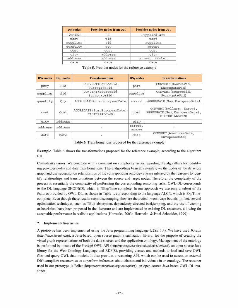
Example. The provider nodes for the target datastore of the reference example are shown in Table 5.
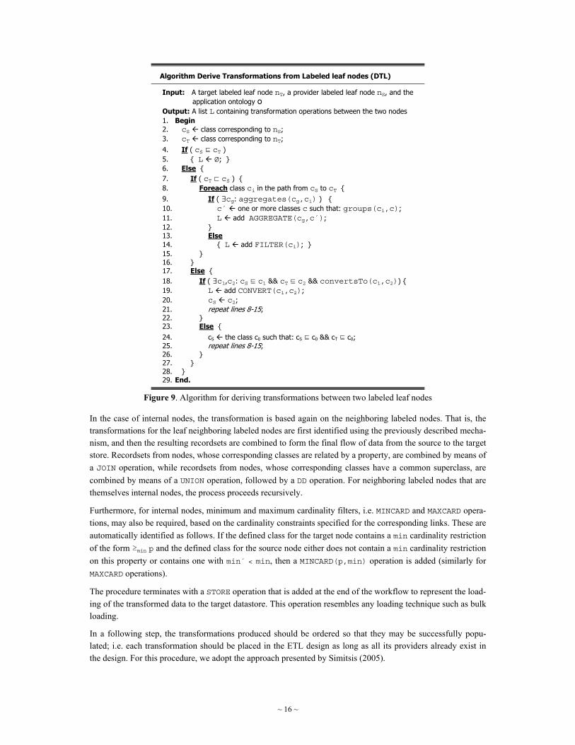
Data transformation. At this stage, the data records extracted from the source need to be appropriately fil-tered, transformed and/or aggregated, so as to satisfy the target constraints and requirements. In the case of two labeled leaf nodes, a source nS and a target nT, the required transformations are identified based on the relative position of their corresponding classes, cS and cT, in the class hierarchy defined in the ontology. Formally, this process is described by the algorithm DTL in Figure 9. The algorithm works as described in the following. Given a source class cS and a target class cT, if cS ⊑ cT holds, then no transformations are required. Otherwise, if cT ⊏ cS holds, only a subset of the source records are compatible with the target constraints. Therefore, an appropriate filtering of the source records is required. In the particular case that the target class represents an aggregated type, then an aggregate operation is required instead of filtering. In different case, the reasoner searches for a superclass of cS that can be converted to a superclass of cT or for a common superclass of cS and cT, and then, it repeats the previous step.
~ 16 ~
Algorithm Derive Transformations from Labeled leaf nodes (DTL)
Input: A target labeled leaf node nT, a provider labeled leaf node nS, and the application ontology O
Output: A list L containing transformation operations between the two nodes 1. Begin 2. cS class corresponding to nS; 3. cT class corresponding to nT; 4. If ( cS ⊑ cT ) 5. { L Ø; } 6. Else { 7. If ( cT ⊏ cS ) { 8. Foreach class ci in the path from cS to cT { 9. If ( ∃cg: aggregates(cg,ci) ) { 10. c΄ one or more classes c such that: groups(ci,c); 11. L add AGGREGATE(cg,c΄); 12. } 13. Else 14. { L add FILTER(ci); } 15. } 16. } 17. Else { 18. If ( ∃c1,c2: cS ⊑ c1 && cT ⊑ c2 && convertsTo(c1,c2)) { 19. L add CONVERT(c1,c2); 20. cS c2; 21. repeat lines 8-15; 22. } 23. Else { 24. cS the class c0 such that: cS ⊑ c0 && cT ⊑ c0; 25. repeat lines 8-15; 26. } 27. } 28. } 29. End.
Figure 9. Algorithm for deriving transformations between two labeled leaf nodes
In the case of internal nodes, the transformation is based again on the neighboring labeled nodes. That is, the transformations for the leaf neighboring labeled nodes are first identified using the previously described mecha-nism, and then the resulting recordsets are combined to form the final flow of data from the source to the target store. Recordsets from nodes, whose corresponding classes are related by a property, are combined by means of a JOIN operation, while recordsets from nodes, whose corresponding classes have a common superclass, are combined by means of a UNION operation, followed by a DD operation. For neighboring labeled nodes that are themselves internal nodes, the process proceeds recursively.
Furthermore, for internal nodes, minimum and maximum cardinality filters, i.e. MINCARD and MAXCARD opera-tions, may also be required, based on the cardinality constraints specified for the corresponding links. These are automatically identified as follows. If the defined class for the target node contains a min cardinality restriction of the form ≥min p and the defined class for the source node either does not contain a min cardinality restriction on this property or contains one with min΄ < min, then a MINCARD(p,min) operation is added (similarly for MAXCARD operations).
The procedure terminates with a STORE operation that is added at the end of the workflow to represent the load-ing of the transformed data to the target datastore. This operation resembles any loading technique such as bulk loading.
In a following step, the transformations produced should be ordered so that they may be successfully popu-lated; i.e. each transformation should be placed in the ETL design as long as all its providers already exist in the design. For this procedure, we adopt the approach presented by Simitsis (2005).
~ 17 ~
DW nodes Provider nodes from DS1 Provider nodes from DS2 PARTSUP PS SuppliedPart pkey pid part
supplier sid supplier quantity qty amount cost cost cost city address city
address address street, number date date date
Table 5. Provider nodes for the reference example
DW nodes DS1 nodes Transformations DS2 nodes Transformations
pkey Pid CONVERT(SourcePid, SurrogatePid) part CONVERT(SourcePid,
SurrogatePid)
supplier Sid CONVERT(SourceSid, SurrogateSid) supplier
CONVERT(SourceSid, SurrogateSid)
quantity Qty AGGREGATE(Sum,EuropeanDate) amount AGGREGATE(Sum,EuropeanDate)
cost Cost AGGREGATE(Sum,EuropeanDate),FILTER(AboveN) cost
CONVERT(Dollars, Euros), AGGREGATE(Sum,EuropeanDate),
FILTER(AboveN)
city address - city -
address address - street,number -
date Date - date CONVERT(AmericanDate, EuropeanDate)
Table 6. Transformations proposed for the reference example
Example. Table 6 shows the transformations proposed for the reference example, according to the algorithm DTL.
Complexity issues. We conclude with a comment on complexity issues regarding the algorithms for identify-ing provider nodes and data transformations. These algorithms basically iterate over the nodes of the datastore graph and use subsumption relationships of the corresponding ontology classes inferred by the reasoner to iden-tify relationships and transformations between the source and target nodes. Therefore, the complexity of the process is essentially the complexity of performing the corresponding reasoning tasks. OWL-DL corresponds to the DL language SHOIN(D), which is NExpTime-complete. In our approach we use only a subset of the features provided by OWL-DL, as shown in Table 1, corresponding to the language ALCN, which is ExpTime-complete. Even though these results seem discouraging, they are theoretical, worst-case bounds. In fact, several optimization techniques, such as TBox absorption, dependency-directed backjumping, and the use of caching or heuristics, have been proposed in the literature and are implemented in existing DL reasoners, allowing for acceptable performance in realistic applications (Horrocks, 2003; Horrocks & Patel-Schneider, 1999).
7. Implementation issues
A prototype has been implemented using the Java programming language (J2SE 1.4). We have used JGraph (http://www.jgraph.com), a Java-based, open source graph visualization library, for the purpose of creating the visual graph representations of both the data sources and the application ontology. Management of the ontology is performed by means of the Protégé-OWL API (http://protege.stanford.edu/plugins/owl/api), an open-source Java library for the Web Ontology Language and RDF(S), providing classes and methods to load and save OWL files and query OWL data models. It also provides a reasoning API, which can be used to access an external DIG compliant reasoner, so as to perform inferences about classes and individuals in an ontology. The reasoner used in our prototype is Pellet (http://www.mindswap.org/2003/pellet), an open-source Java-based OWL-DL rea-soner.

~ 18 ~
(a) (b)
Figure 10. Results of (a) PNS and (b) DTL algorithms for our reference example
An example result concerning the population of the DW from the source DS2 is depicted in Figure 10. Figure 10(a) represents the provider nodes of DS2 resulting from the algorithm PNS, and Figure 10(b) lists the trans-formations proposed according to the algorithm DTL.
8. Conclusions
In this paper, we dealt with a crucial issue that arises in the early stages of a Data Warehouse project: the prob-lem of identifying the appropriate transformations and specification of inter-schema mappings that should drive the flow of data from the data sources to the target Data Warehouse. We proposed an ontology-based approach to facilitate the conceptual design of an ETL process. Both structured and semi-structured datastores are con-ceptually represented by a graph, termed datastore graph. Heterogeneity is resolved using Semantic Web tech-nologies. Datastores are semantically annotated by a suitable ontology described in OWL-DL, and the map-pings between them can be subsequently inferred. Based on the application ontology and the annotated datas-tore graphs, automated reasoning techniques are used to infer correspondences and conflicts among the datas-tores; thus, identifying relevant sources and proposing conceptual operations for integrating data into the Data Warehouse.
As future work is concerned, we investigate the possibility to use the aforementioned techniques to automati-cally design an appropriate schema for a Data Warehouse based on a given set of source, structured or semi-structured, datastores. Also, we already have some preliminary results on the study of the impact of changes to an ETL scenario using an ontology based approach. Finally, we plan to evaluate the theoretical properties of our method via the reverse engineering of real-world ETL scenarios, originated from an application of the Greek public sector.
Acknowledgements. This work is co-funded by the European Social Fund (75%) and National Resources (25%) - Operational Program for Educational and Vocational Training II (EPEAEK II) and particularly the Program PYTHAGORAS.
References
Abiteboul, S. (1997). Querying semi-structured data. In Proc. of the International Conference on Database Theory, 1-18.
Abiteboul, S., Suciu, D., & Buneman, P. (2000). Data on the Web: From Relations to Semi-structured Data and XML. San Francisco, CA: Morgan Kaufmann.
Arens, Y., Knoblock, C. A., & Shen, W.-M. (1996). Query reformulation for dynamic information integration. International Journal on Intelligent and Cooperative Information Systems, 6(2/3), 99-130.
Arenas, M., & Libkin, L. (2005). XML data exchange: consistency and query answering. In Proceedings of the 24th ACM SIGMOD-SIGACT-SIGART Symposium on Principles of Database Systems, 13-24.
Ballard, C. (1998). Data Modeling Techniques for Data Warehousing. IBM Red Book.
Beeri, C., Levy, A. Y., & Rousset, M.-C. (1997). Rewriting queries using views in description logics. In Proc. of the 16th ACM SIGACT-SIGMOD-SIGART Symposium on Principles of Database Systems, 99-108.
~ 19 ~
Baader, F., Calvanese, D., McGuiness, D. L., Nardi, D., & Patel-Schneider, P. F. (2003). The Description Logic Handbook: Theory, Implementation, Applications. Cambridge, UK: Cambridge University Press.
Bianchini, D., & De Antonellis, V. (2004). Ontology-based integration for Sharing Knowledge over the Web. CAiSE International Workshop on Data Integration over the Web, 82-89.
Borst, W. N. (1997). Construction of Engineering Ontologies. PhD thesis, University of Twente, Enschede.
Boehnlein, M., & Ulbrich-vom Ende, A. (1999). Deriving the Initial Data Warehouse Structures from the Conceptual Data Models of the Underlying Operational Information Systems. In Proc. of the ACM 2nd International Workshop on Data Warehousing and OLAP, 15-21.
Buneman, P. (1997). Semistructured data. In Proc. of the ACM SIGACT-SIGMOD-SIGART Symposium on Principles of Database Systems, 117-121.
Calvanese, D., De Giacomo, G., & Lenzerini, M. (1999). Answering queries using views in description logics. In Working notes of the Knowledge Representation Meets Databases Workshop, 6-10.
Calvanese, D., De Giacomo, G., & Rosati, R. (1999). Data Integration and Reconciliation in data Warehousing: Conceptual Modeling and Reasoning Support. Networking and Information Systems, 2(4), 413-432.
Catarci, T., & Lenzerini, M. (1993). Representing and using interschema knowledge in cooperative information systems. Journal of Intelligent and Cooperative Information Systems, 2(4), 375-398.
Calì, A., Calvanese, D., De Giacomo, G., & Lenzerini, M. (2004). Data integration under integrity constraints. Information Systems, 29(2), 147-163.
Fagin, R., Kolaitis, P. G., & Popa, L. (2005). Data Exchange: Getting to the Core. ACM Transactions on Database Systems, 30(1), 174–210.
Fagin, R., Kolaitis, P. G., Miller, R. J., & Popa, L. (2005). Data exchange: semantics and query answering. Theoretical Computer Science, 336(1), 89-124.
Garcia-Molina, H., Papakonstantinou, Y., Quass, D., Rajaraman, A., Sagiv, Y., Ullman, J. D., Vassalos, V., & Widom, J. (1997). The TSIMMIS Approach to Mediation: Data Models and Languages. Journal of Intelligent Information Systems, 8(2), 117-132.
Golfarelli, M., Lechtenbörger, J., Rizzi, S., & Vossen, G. (2006). Schema versioning in data warehouses: enabling cross-version querying via schema augmentation. Data & Knowledge Engineering, 59(2), 435-459.
Golfarelli, M., & Rizzi, S. (1998). Methodological Framework for Data Warehouse Design. In Proc. of the ACM 1st International Workshop on Data Warehousing and OLAP, 3-9.
Golfarelli, M., Rizzi, S., & Vrdoljak, B. (2001). Data warehouse design from XML sources. In Proc. of the ACM 4th International Workshop on Data Warehousing and OLAP, 40-47.
Halevy, A. Y. (2001). Answering queries using views: A survey. The VLDB Journal, 10(4), 270-294.
Hahn, K., Sapia, C., & Blaschka, M. (2000). Automatically Generating OLAP Schemata from Conceptual Graphical Models. In Proc. of the ACM 3rd International Workshop on Data Warehousing and OLAP, 9-16.
Horrocks, I. (2003). Implementation and optimisation techniques. In F. Baader, D. Calvanese, D. McGuinness, D. Nardi, P. F. Patel-Schneider (Eds.), The Description Logic Handbook: Theory, Implementation, and Applications. Cambridge University Press, 306–346.
Horrocks, I., & Patel-Schneider, P. F. (1999). Optimizing description logic subsumption. Logic and Computation, 9(3), 267-293.
Hüsemann, B., Lechtenbörger, J., & Vossen, G. (2000). Conceptual data warehouse modeling. In Proc. of the 2nd International Workshop on Design and Management of Data Warehouses, 6.1-6.11.
IBM. IBM Data Warehouse Manager. URL http://www-3.ibm.com/software/data/db2/datawarehouse/
Informatica. PowerCenter. URL http://www.informatica.com/products/powercenter/
Kimball, R., & Caserta, J. (2004). The Data Warehouse ETL Toolkit. John Wiley & Sons.

~ 20 ~
Kimball, R., et al. (1998). The Data Warehouse Lifecycle Toolkit. John Wiley & Sons.
Kolaitis, P. G., Panttaja, J., & Tan, W. C. (2006). The complexity of data exchange. In Proc. of the 25th ACM SIGMOD-SIGACT-SIGART Symposium on Principles of Database Systems, 30-39.
Lenzerini, M. (2002). Data Integration: A Theoretical Perspective. In Proc. of the 21st ACM SIGMOD-SIGACT-SIGART Symposium on Principles of Database Systems, 233-246.
Libkin, L. (2006). Data exchange and incomplete information. In Proc. of the 25th ACM SIGMOD-SIGACT-SIGART Symposium on Principles of Database Systems, 60-69.
Luján-Mora, S., Vassiliadis, P., & Trujillo, J. (2004). Data Mapping Diagrams for Data Warehouse Design with UML. In Proc. of the 23rd International Conference on Conceptual Modeling, 191-204.
Microsoft. Data Transformation Services. URL http://www.microsoft.com/sql/prodinfo/features/
Moody, D.L., & Kortink, M.A.R. (2000). From Enterprise Models to Dimensional Models: a Methodology for Data Warehouse and Data Mart Design. In Proc. of the 3rd International Workshop on Design and Management of Data Warehouses, 5.1-5.12.
Mazon, J-N., Trujillo, J., Serrano, M., & Piattini, M. (2005). Applying MDA to the development of data warehouses. In Proc. of 8th ACM International Workshop on Data Warehousing and OLAP, 57-66.
Oracle. Oracle Warehouse Builder Product Page.URL http://otn.oracle.com/products/warehouse/content.html
Peralta, V. (2003). Data Warehouse Logical Design from Multi-dimensional Conceptual Schemas. CLEI.
Phipps, C., & Davis, K. (2002). Automating Data Warehouse Conceptual Schema Design and Evaluation. In Proc. of the International Workshop on Design and Management of Data Warehouses, 23-32.
Popa, L., Velegrakis, Y., Miller, R. J., Hernandez, M. A., & Fagin, R. (2002). Translating Web Data. In Proc. of the International Conference on Very Large Data Bases, 598-609.
Papadakis, N., Skoutas, D., Raftopoulos, K., & Varvarigou, T. (2005). STAVIES: A System for Information Extraction from Unknown Web Data Sources through Automatic Web Wrapper Generation Using Clustering Techniques. IEEE Transactions on Knowledge and Data Engineering, 17(12), 1638-1652.
Rahm, E., & Bernstein, P. (2001). A survey of approaches to automatic schema matching. The VLDB Journal, 10(4), 334-350.
Rodríguez-Gianolli, P., & Mylopoulos, J. (2001). A Semantic Approach to XML-based Data Integration. In Proc. of the 20th International Conference on Conceptual Modeling, 117-132.
Simitsis, A. (2005). Mapping Conceptual to Logical Models for ETL Processes. In Proc. of the 8th ACM International Workshop on Data Warehousing and OLAP, 67 - 76.
Skoutas, D., & Simitsis, A. (2006). Designing ETL Processes Using Semantic Web Technologies. In Proc. of the 9th ACM International Workshop on Data Warehousing and OLAP.
Smith, M. K., Welty, C., & McGuinness, D. L. (2004). OWL Web Ontology Language Guide. W3C Recommendation. URL http://www.w3.org/TR/owl-guide/
Trujillo, J., & Lujan-Mora, S. (2003). A UML Based Approach for Modeling ETL Processes in Data Warehouses. In Proc. of the 22nd International Conference on Conceptual Modeling, 307-320.
Vassiliadis, P., Simitsis, A., Georgantas, P., Terrovitis, M., & Skiadopoulos, S. (2005). A Generic and Customizable Framework for the Design of ETL Scenarios. In Information Systems, 30(7), 492 - 525.
Vassiliadis, P., Simitsis, A., & Skiadopoulos, S. (2002). Conceptual Modeling for ETL Processes. In Proc. of the 5th ACM International Workshop on Data Warehousing and OLAP, 14-21.