OILLESS SCROLL AIR COMPRESSORS - coaire.com manuals/new/CSOF-M3~5,S3~10...5 2.0 Safety and Warning...
54
For proper and safe use of the compressor, please follow all instructions and safety precautions as identified in this manual, along with general safety regulations and practices. April, 2015 OILLESS SCROLL AIR COMPRESSORS MAINTENANCE MANUAL AND PARTS LIST All rights reserved Printed in U.S.A. CSOF-S5PL/H22 CSOF-S5PL/H32 CSOF-S5PL/H42 CSOF-S5PL/H52 CSOF-S8PL/H22 CSOF-S8PL/H32 CSOF-S8PL/H42 CSOF-S8PL/H42 CSOF-S10PL/H22 CSOF-S10PL/H32 CSOF-S10PL/H42 CSOF-S10PL/H52 CSOF-M3PL/H12 CSOF-M3PL/H22 CSOF-M3PL/H32 CSOF-M3PL/H42 CSOF-M3PL/H52 CSOF-M5PL/H22 CSOF-M5PL/H32 CSOF-M5PL/H42 CSOF-M5PL/H52 CSOF-S3PL/H12 CSOF-S3PL/H22 CSOF-S3PL/H32 CSOF-S3PL/H42 CSOF-S3PL/H52
Transcript of OILLESS SCROLL AIR COMPRESSORS - coaire.com manuals/new/CSOF-M3~5,S3~10...5 2.0 Safety and Warning...

For proper and safe use of the compressor please follow all instructions and safety precautions as identified in
this manual along with general safety regulations and practices
April 2015
OILLESS SCROLL AIR COMPRESSORS MAINTENANCE MANUAL AND PARTS LIST
All rights reserved Printed in USA
CSOF-S5PLH22 CSOF-S5PLH32 CSOF-S5PLH42 CSOF-S5PLH52
CSOF-S8PLH22 CSOF-S8PLH32 CSOF-S8PLH42 CSOF-S8PLH42
CSOF-S10PLH22 CSOF-S10PLH32 CSOF-S10PLH42 CSOF-S10PLH52
CSOF-M3PLH12 CSOF-M3PLH22 CSOF-M3PLH32 CSOF-M3PLH42 CSOF-M3PLH52
CSOF-M5PLH22 CSOF-M5PLH32 CSOF-M5PLH42 CSOF-M5PLH52
CSOF-S3PLH12 CSOF-S3PLH22 CSOF-S3PLH32 CSOF-S3PLH42 CSOF-S3PLH52
3
STATEMENT OF WARRANTY TERMS amp CONDITIONS
8750 Pioneer Blvd Santa Fe Springs CA 90670
All freight damage claims should be filed within 15 working days and should be directed to the carrier
General Provisions a) Coaire warrants our air compressors and scroll systems (henceforth called ldquoproductsrdquo) to be free from material defects and
workmanship under proper use operating conditions installation and application based on the terms and conditions set forth below Coaire offers no other warranty whether expressed or implied including any warranty of merchantability or fitness for a particular purpose
b) Any air compressor part or material found to be defective will be repaired replaced or refunded at the sellers option free of charge provided that Coaire is notified with the stated warranty period
c) All claims shall be made in writing using our warranty claim report located within each service manual d) All claims must have the start-up report sheet included The start-up report sheet is located within each service manual e) All returns of allegedly defective equipment must have prior written authorization Said authorization shall be obtained through our
service department Any compressors parts or materials must be returned freight prepaid to the manufacturers factory within (30) days of the return authorization date Any shipment returned to the factory collect will be refused
f) If an item is found to be warrantable the repaired or replacement item will be returned normal ground freight prepaid Expedited return freight costs are the responsibility of the requestor
g) Any replacement part or material is warranted to the extent of the remaining warranty period Standard Period of Warranty
h) Coaire warrants our system(s) for a period of (15) months from shipment (12) months from the documented start-up or 5000 hours of use whichever occurs first During such period Coaire will be liable for all product or material defects and will assume the costs of repair or replacement so long as the product(s) are located within the continental United States or Canada In addition the product(s) must be easily accessible by service personnel for removal
i) In addition to item ldquogrdquo above Coaire warrants the air compressor air end (compressor only) parts only (no labor) for a period of (27) months from shipment (24) months from the documented start-up or 7500 hours of use whichever occurs first
j) Coaire product(s) located outside of the continental United States or Canada shall include a parts only warranty for a period of (15) months from shipment (12) months from the documented start-up or 5000 hours of use whichever occurs first
Exclusions ndash Coaire shall have no warranty obligation for
k) Products not installed in accordance with our written instructions and specifications l) Operated in an unsuitable environment in excess of stated product parameters modified in any way or used in an improper
manner m) That have not been properly maintained per Coairersquos written instructions n) Use of corrosive materials or insoluble lubricants o) Normal wear and tear items are not included under this warranty p) Any OEM (original equipment manufacturer) component that may be used within our products will carry the original manufacturerrsquos
warranty q) Product is properly stored prior to installation r) Product not installed by a competent qualified installer s) Product which may have been damaged during shipment
Liability Limitation
t) Coaire shall not be liable for any damages (incidental consequential punitive et al) that may arise from the use of our product Coairersquos liability in all events is limited to and shall not exceed the original purchase price
Suitability of the Product
u) Jurisdictions has various codes Coaire makes no claim as to the suitability for all jurisdictions It is the buyerrsquos responsibility to ensure the product installation and use comply with local jurisdictions
Identification plate
v) Coaire products have identification plates on the air compressors as well as on the enclosures These data plates show the primary information for the product This data should always be referred to when calling the manufacturer or distributor The removal or alteration of the identification plate(s) shall immediately void all warranty
Who to contact for warranty claims Web wwwcoairecom
Phone (562) 496-3935 Fax (562) 463-4928
WARRANTY
4
10 Table of contents -------1 70 Control
7-1 Controller ------24
20 Safety and warnings 7-2 Major functions ------24
2-1 General -------2 7-3 Configuration of functions ------25
2-2 Safety caution -------2 7-4 Error messages ------30
2-3 Safety and warnings -------4
80 Maintenance
30 General 8-1 Scheduled Maintenance (L) ------32
3-1 Specification -------7 8-2 Scheduled Maintenance (H) ------33
3-2 Major component -------8 8-3 Maintenance ------34
3-3 System diagram ------11
90 Trouble Shooting
40 Installation 9-1 Overview ------37
4-1 Inspection ------13 92 Flow diagram for trouble shooting ------37
4-2 Handling ------13 93 Other trouble shooting ------40
4-3 Installation ------14
4-4 Requirements for the piping ------16 100 Outline drawings
4-5 Wiring ------16 10-1 CSOF-S3PL(H)P CSOF-S5PL(H)P ------41
10-2 CSOF-M3PL(H) CSOF-M5PL(H) ------42
50 Operation 10-3 CSOF-S8PL(H) CSOF-S10PL(H) ------43
5-1 Commissioning ------19
5-2 Routine operation ------20 110 Electrical wiring drawings
11-1 CSOF-S35PL(H)P CSOF-M35PL(H) ------44
60 Functional descriptions 11-2 CSOF-S8PL(H) CSOF-S10PL(H) ------45
6-1 Airend ------22 11-3 CSOF-S35PL(H)P M35PL(H) 1PH ------46
6-2 Motor ------22 11-4 CSOF-S8PL(H) CSOF-S10PL(H) 1PH ------47
6-3 Fan ------23
6-4 Cooler ------23 Operation record form
6-5 Suction filter ------23 Product guarantee
6-6 Check valve ------23 Installation report
CONTENTS
10 Table of contents
5
20 Safety and Warning
SAFETY AND WARNINGS
1) Air compressor should be manipulated by the person who had adequate safety and operation training
2) Be familiarize with userrsquos manual and safety instruction before using
3) This compressor can not be used for human breathing
4) Do not put flammable things near the air compressor
5) Please use genuine parts if not we can not guarantee the product quality
6) User should keep relevant safety laws and regulations
7) If user adds a control circuit to the product or attempt to modify or alter the product without permission
it may cause damages on the product due to the malfunction of the protective devices
which may not be covered by the warranty Then the product could be repaired by our pay service
All the problems occurs not following this manual is the responsibility of user
2-1 General
2-2 Symbol
bull Caution is used to indicate the presence of a hazard which will or can cause
minor personal injury or property damage if the warning is ignored
bull Warning is used to indicate the presence of a hazard which can cause severe
personal injury death or substantial property damage if the warning is ignored
bull Danger is used to indicate the presence of a hazard which will cause severe
personal injury death or substantial property damage if the warning is ignored
bull Cut off main power before air compressor check or maintenance
Can cause severe injury or death
bull Install in an area which is not exposed to moisture such as rain steam(indoor
only) If not it can cause electric shock
bull Connect the grounding to the grounding terminal inside the control box
Without grounding it may cause an electric shock or a fire
bull Please install the product in areas free of explosives
(acetylene propane gas etc)or flammable substances
bull Do not put flammable things near the air compressor Once flammable
materials come to the airend inside it may cause a fire or an explosion
bull Do not install the compressor in a place with 40 119848119851 higher ambient
temperature It may cause a fire or damages on the compressor
bull Do not try welding or any similar works around the compressor
Flames or spark may cause internal explosion when sucked into the airend
CAUTION
WARNING
DANGER
6
SAFETY AND WARNINGS
bull Do not operate without safety guard in place
bull Operation without safety guard can cause severe injury
bull When the circuit breaker is turned on during the operation do not touch
the circulation parts (fan pulley belt etc)
Your hand may get stuck to the product
bull When the compressor is operating the product will be operated or stopped
automatically based on the pressure Please be aware of the safety feature
bull High pressure air can cause severe injury or death
Relieve pressure before removing filter plugscaps fitting or covers
bull A special attention should be paid on a safe valve because it can be operated
during operation
bull When opening the door or disassembling the panel for inspection repair
or maintenance during or after operation do not touch the product directly
with the hand And do not insert flammable materials in hot areas such as
discharge pipe after-cooler basic compressor or etc These can be danger of
fire or burning
bull Never directly inhale the compressed air and never use for the food processing
industry It may cause major damage to the human body
bull Read and understand user manual before using air compressor
bull The installation operation repair and electric works of the product should be
executed by a qualified(licensed) person
bull Check the control box inside clean and bolt Joints regularly
bull Do not modify the machine and circuits without permission of the
manufacturer
7
SAFETY AND WARNINGS
WARNINGIn case of change setting pressure higher
than written pressure in name plate
Will cause malfuction injury or death
DANGERHigh pressure Safelydepressurize the air pressureFlying parts from compressedair can cause injury or death
DANGERCompressed air contains
harmful material Never use
air to supply breathing air
DANGERKeep hands foot and clothingaway from driven parts Willcause injury or death
WARNINGRead and understand user manual
before using air compressor
Connect the grounding to
the grounding terminal inside
the control box
DANGER
HAZARDOUS VOLTAGE ISIDE
SHUT OFF POWER WILL
SHOCK CAUSE INJURY OR
DEATH
DANGER
DO NOT TOUCH
HOT SURFACE
WILL CAUSE INJURY
WARNING
DANGERDo not weld or any
similar works around the
compressor
2-3 Safety and Warnings
2-3-1 CSOF-S3PL(H)P CSOF-S5PL(H)P
[ Fig 2-2 ] Rear Side
[ Fig 2-1 ] Front Side
8
2-3 Safety and Warnings
2-3-2 CSOF-M3PL(H) CSOF-M5PL(H)
WARNINGRead and understand user manual
before using air compressor
DANGERHigh pressure Safelydepressurize the air pressureFlying parts from compressedair can cause injury or death
DANGERDo not weld or any
similar works around the
compressor
WARNINGIn case of change setting pressure higher
than written pressure in name plate
Will cause malfuction injury or death
Connect the grounding to
the grounding terminal inside
the control box
DANGER
HAZARDOUS VOLTAGE ISIDE
SHUT OFF POWER WILL
SHOCK CAUSE INJURY OR
DEATH
DANGER
DO NOT TOUCH
HOT SURFACE
WILL CAUSE INJURY
WARNING
DANGERCompressed air contains
harmful material Never use
air to supply breathing air
DANGERKeep hands foot and clothingaway from driven parts Willcause injury or death
DO NOT TOUCH
HOT SURFACE
WILL CAUSE INJURY
WARNING
[ Fig 2-4 ] Rear Side
[ Fig 2-3 ] Front Side
SAFETY AND WARNINGS
9
WARNINGRead and understand user manual
before using air compressor
Check the control box inside for bolt
tightness and cleaning periodically
DANGERHigh pressure Safely depressurizethe air pressure Flying parts fromcompressed air can cause injury ordeath
DANGERDo not weld or any
similar works around the
compressor
WARNINGIn case of change setting pressure higher
than written pressure in name plate
Will cause malfuction injury or death
Connect the grounding to
the grounding terminal inside the
control box
DANGER
HAZARDOUS VOLTAGE ISIDE
SHUT OFF POWER WILL
SHOCK CAUSE INJURY OR
DEATH
DANGER
DO NOT TOUCH
HOT SURFACE
WILL CAUSE INJURY
WARNING
DANGERCompressed air contains
harmful material Never use
air to supply breathing air
DANGERKeep hands foot and clothingaway from driven parts Will causeinjury or death
DO NOT TOUCH
HOT SURFACE
WILL CAUSE INJURY
WARNING
DANGERKeep hands foot and clothingaway from driven parts Will causeinjury or death
Do not operate without safety
guard in place
[ Fig 2-6 ] Rear Side
[ Fig 2-5 Front Side ]
2-3-3 CSOF-S8PL(H) CSOF-S10PL(H)
SAFETY AND WARNINGS
10
3-1 Specification
Note 1 Noise level is the measurement from acoustic room 2 The size is the size of the external design of the package Protruding areas such as discharge ball valve have been excluded in the measurement
Model CSOF-M3PL(H)
[S3PL(H)P]
CSOF-M5PL(H)
[S5PL(H)P] CSOF-S8PL(H) CSOF-S10PL(H)
UNIT
Type Single Stage Oil Free Scroll Air Compressor
Air
Delivery
(LPMCFM)
08 Mpa
115 PSI 270 85 415 141 685 226 830 283
099 Mpa
140 PSI 220 72 350 120 570 192 700 24
Driving
Method Belt 3V-360x2EA 3V-380x2EA 3V-380x4EA 3V-405x4EA
High temp stop () 80 176
MOTOR
Output ( kWhp ) 223 375 223 x 1SET
375 x 1SET 375 x 2SET
Voltage ( V ) 115 208-230 460 575
Frequency ( Hz ) 60
Poles 4
Starting Method DIRECT ON LINE
GENERAL
Air Outlet A(B) 15 (12rdquo) 25(1rdquo)
Receiver Tank (Liter ) 38 [NA] NA
Cooling Type Air Cooled
Service air temp ()
Amb Temp
+2240
[ 2781]
Amb Temp
+2745
[ 2781]
Amb Temp+2545
Ambient temp () Max40
Noise Level (dB(A)) 49plusmn5 50plusmn5 52plusmn5 53plusmn5
DIMENSION
Length (mminch) 700 276 [550216] 640 252
Width (mminch) 740 291 [670263] 1150 465
Height (mminch) 1070 421 [780307] 1020 402
Weight (kglb) 123 271
[1102425]
150 330
[1152535] 233 536 256 587
30 General
GENERAL
11
3-2 Major Component
3-2-1 CSOF-S3PL(H)P CSOF-S5PL(H)P
[ Fig3-1 ] Rear View
[ Fig3-2 ] Front View
DESCRIPTION
1 COMMON BASE
2 COVER amp FRAME
3 AIREND
4 MOTOR
5 MOTOR PULLEY
6 AIREND PULLEY
7 SUCTION FILTER
8 AIR DELIVERY PIPE
9 AIR DISCHARGE PIPE
10 AIR COOLER
11 COOLING FAN
12 CONTROLLER
13 CONTROL BOX
14 V-BELT
15 CHECK VALVE
16 SAFETY VALVE
17 DRAIN VALVE
18 PRESSURE TRANSMITER
111
2
7
8
12
13
15
3
4
5
6
9
10
14
16
17
18
GENERAL
12
12
13
1
10
11
5
14
6
2
3
7 4
8
18
17
15
16
9
19
3-2-2 CSOF-M3PL(H) CSOF-M5PL(H)
DESCRIPTION
1 COMMON BASE
2 COVER amp FRAME
3 AIREND
4 MOTOR
5 MOTOR PULLEY
6 AIREND PULLEY
7 SUCTION FILTER
8 AIR RECEIVER TANK
9 AIR DELIVERY PIPE
10 AIR COOLER
11 COOLING FAN
12 CONTROLLER
13 CONTROL BOX
14 V-BELT
15 CHECK VALVE
16 SAFETY VALVE
17 DRAIN VALVE
18 PRESSURE TRANSMITTER
19 EMERGENCY SWITCH [ Fig3-3 ] Outline View
[ Fig3-5 ] Rear View [ Fig3-4 ] Front View
GENERAL
13
1
13
2
2
3
4
5
6
7
89
10
11
12 19
14
15
16
17
18
3-2-3 CSOF-S8PL(H) CSOF-S10PL(H)
[ Fig3-8 ] Rear View [ Fig3-7 ] Right View
DESCRIPTION
1 COMMON BASE
2 COVER amp FRAME
3 AIREND
4 MOTOR
5 MOTOR PULLEY
6 AIREND PULLEY
7 SUCTION FILTER
8 AIR DELIVERY SOCKET
9 AIR DELIVERY PIPE
10 AIR COOLER
11 COOLING FAN
12 CONTROLLER
13 CONTROL BOX
14 V-BELT
15 CHECK VALVE
16 SAFETY VALVE
17 DRAIN VALVE
18 PRESSURE TRANSMITTER
19 EMERGENCY SWITCH [ Fig3-6] Left View
GENERAL
14
3-3 System Diagram
3-3-1 CSOF-M(S)3PL(H)(P) CSOF-M(S)5PL(H)(P)
The CSOF Series are an oil-free scroll air compressor In an operation a main motor is run to
initiate the compression at an airend The external air is filtered through a suction filter before
entering into the airend The compressed air is stored into an air tank via a check valve (non-return
valve) The temperature of the compressed air discharged from the airend is at least 200degC(392)
The air is primarily cooled in an air tank and secondarily via an air cooler before being discharged
The saturated vapor phase compressed air condenses into a water that can manually be discharged
via a drain valve in the air tank
There are following four safeguards in CSOF-M(S)3PL(H) and CSOF-M(S)5PL(H) models
1) Over Current Relay (OCR) for Motor ndash Detects the over current of the motor to stop the
compressor
2) Mechanical Safety Valve ndash Mechanically discharges the compressed air in the air tank to the
air if the air pressure exceeds the set value The compressor shall manually be stopped
3) Temperature Sensor (Temperature Transmitter ) ndash Detects the temperature exceeding the set
value (80degC176) at the bottom of the airend to stop the compressor
4) Pressure Sensor (Pressure Transmitter ) ndash Detects the pressure in the air tank and sends the
value to the controller to stop the compressor if the air pressure exceeds the set value
[ Fig3-9 ] System Diagram
GENERAL
CSOF-S35PL(H)P
CSOF-M35PL(H)
15
3-3-2 CSOF-S8PL(H) CSOF-S10PL(H)
[ Fig3-10 ] System Diagram
The basic principle of the CSOF-S8PL(H) and CSOF-S10PL(H) is equal to that of CSOF-M3PL(H)
and CSOF-M5PL(H) However the CSOF-S8PL(H) and CSOF-S10PL(H) have two airend to
sequentially be started up depending on the load to be used As there is no air tank in the
compressor a drain valve is used on the discharge end to drain the condensate water generated
during the compression For the CSOF-S8PL(H) or above an air receiver tank shall separately be
ordered and installed by the amount of air used The tank capacity varies depending on the load
to be used for example minimum capacity is 60 liters for the CSOF-S8PL(H) and 80 liters for the
CSOF-S10PL(H)
There are following four safeguards in CSOF-S8PL(H) and CSOF-S10PL(H) models
1) Over Current Relay (OCR) for Motor ndash Detects the over current of each motor to stop only the
motor failed
2) Mechanical Safety Valve ndash Mechanically discharges the compressed air in the air tank to the
air if the air pressure exceeds the set value The compressor shall manually be stopped
3) Temperature Sensor (Temperature Transmitter ) ndash Detects the temperature exceeding the set
value at the bottom of each airend to stop only the motor failed
4) Pressure Sensor (Pressure Transmitter ) ndash Detects the pressure in the air tank and sends the
value to the controller to stop the compressor if the air pressure exceeds the set value
GENERAL
16
40 Installation
[ Fig4-1 ] Name plate
4-2 Handling
4-2-1 Handling by a forklift
When handling by a forklift make sure that forks completely extend through the width of the unit (Fig4-2)
4-2-2 Handling by a shop crane
When handling by a shop crane use the openings provided on common base where slings or steel wire
ropes can be use for lifting (Fig 4-3)
[ Fig4-2 ] [ Fig4-3 ]
4-1 Inspection
When you receive the compressor please inspect it close
Upon received check the compressor damage carefully
during the transportation
If goods are received in damaged condition it is important
that you notify the carrier and insist on a notation of loss or
damage across the freight bill
INSTALLATION
17
4-3-2 Ventilation
4-3-1 Where to Install
Poor ventilation in the compressor room may raise the temperature of the air discharged
If the room temperature exceeds 10degC(18) more than the outside temperature sufficiently
Ventilate the air in the room(see Table 4-1) and install the exhaust duct if necessary
COAIRE air compressor is designed for the indoor use The ventilation facility and piping affect
the performance and the service life of the compressor Please follow the instructions in the userrsquos
manual
[ Fig4-4 ] Installation of the Air Compressor
MIN
1ft
MIN
32
8ft
MIN 492ft MIN 656ft
V=984fts below
V=164fts below
EMERGENCY
STOP
[ Fig4-5 ] Installation of the Exhaust Duct
FLEXIBLEHOSE
BALLVALVE
4-3 Installation
INSTALLATION
18
4-3-3 Selection of Where to Install
Item Description
Place - Do not install the compressor unit on the outside
- Please keep warm during the winter season if you have to install on the outside
Space
- Keep the space of more than 08m(263ft) from the wall to facilitate the repair
and maintenance of the compressor
- Do not place any object in front of the door
Floor and
Foundation
- The floor shall sufficiently holds the weight of the compressor
- The floor surface shall be flat with a gradient less than 1 degree to minimize
the vibration
- It is recommended to install the compressor 10cm(394rdquo) above the floor though
COAIRE air compressor generates an insignificant amount of vibration
Room
Temperature
- Optimal ambient temperature is 0-40degC(32~104) during the operation
- Install the compressor at low temperature and moisture if possible
Each 10degC(18) increase of the inlet temperature reduces the efficiency of the
compressor by 3-4
Hazardous
Substances
- Install the compressor at the place where there is the least noxious gas
hazardous substance and dust Those foreign substances may cause the damage
of the air compressor
Electricity - The electric power shall have at least 150 of the reference margin
- The range of fluctuation in voltage shall be within plusmn10
Ventilation
- A ventilation fan shall be installed to forcedly ventilate the room if the room
temperature exceeds 10degC(18) more than the outside temperature in the
summer
- For an exhaust duct set the velocity at 5 ms(164fts) and the static pressure at
less than 5 mmAq
- Install a protective net on the exhaust outlet to prevent birds rodents and
foreign substances from entering
- Place the inlet as low as possible
[table 4-2] Requirements for Where to Install
Model Air Volume
[CMM CFM ]
Hood Size
[ mm x mm ft x ft ]
CSOF-M3PL(H) CSOF-M5PL(H)
CSOF-S3PL(H)P CSOF-S5PL(H)P 30 1059 300 x 600 1 x 197
CSOF-S8PL(H) CSOF-S10PL(H) 60 2118 400 x 800 131 x 263
[ Table 4-1 ] Ventilation Fan Capacity
INSTALLATION
19
4-5 Wiring
1) Extremely low or high voltage power supply may cause the failure of the compressor Low power
capacity also causes significant voltage drop when starting up the compressor The compressor
requires at least 85 of the rated voltage for a start-up which shall be maintained within plusmn10 of
the rated voltage during the operation The inter-phase voltage imbalance shall be within 2 not
exceeding 3 even in a special case
2) Features and Capacity
See Table 4-4 Electrical Specification for an appropriate electric power an operating current and a
starting current Considering that the discharge air pressure abnormally exceeding the rated
operating pressure increases the operating current wiring shall allow about 120 of the rated
capacity of a main transformer
3) See Table 4-4 Electrical Specification for the electric power [kW] and the power factor []
4) Minimum Capacity of Transformer [kVA] = Electric Power [kW] Power Factor [] x 100 x 12
5) Longer lead-in wiring of the main power may cause the compressor failed or tripped during the
start-up due to the voltage drop in the line Select the thickness of the cable so that it maintains at
least minimum starting voltage
6) The calculation of the voltage drop based on the line length is as follows 3-Phase 3-Line Type Connection Where I = Current [A] A = Cross Section of Cable [mm2] e = Voltage Drop [V] L = Length of Cable [M]
4-4 Requirements for the Piping
1) Use a larger diameter and install the pipe without an excessive bending to reduce the pressure
drop
2) Always place a branch pipe on the top of a main pipe to reduce the discharge of oil or water
3) For the compressed air pipes reduce the number of sections bending and connecting and the
number of valves installed to reduce the pressure loss
4) The increased pressure loss requires a high discharge pressure of the air compressor
Consequently it causes the power loss The water stays wherever the pipe is sagging to increase
the pipe resistance which may cause winter-sowing Thus consider the pipe straightness when
installing the pipes
5) Install a bypass piping on each equipment for a maintenance
6) A scroll air compressor has a check valve in the system Installing more check valves between the
compressor and the air receiver tank may cause a malfunction of the compressor
7) Always install a drain valve on the bottom of a vertical pipe for the prevention of a winter-sowing
e = 308 x L x I
1000 x A
INSTALLATION
20
INSTALLATION
7) It is recommended that the thickness of the cable shall allow more than the minimum requirement
specified for a power condenser and the length of the cable shall be within 15m(492ft) No wiring is
necessary if there is a power condenser with a sufficient capacity in the bus conductor
8) Leave intact the factory specification of the overcurrent protection device If the change is unavoidable
keep the set values within the range specified in the userrsquos manual The cable shall allow more than the
minimum requirement specified
9) As the operating current varies depending on a given condition it is recommended to allow about 20
extra
10) Install a circuit breaker in the main power to protect the motor The circuit breaker shall have a built-in
electric leak breaker
11) Use the ground terminal on a motor or a control box to earth the equipment
[ Table4-3 ] MINIMUM COPPER EARTHING CONDUCTOR SIZE
Nominal size of active conductor(mm2)
Nominal size of copper earthing conductor
mm2
With copper active conductors
With Aluminum active conductors
1 1 -
15 15 -
25 25 -
4 25 -
6 25 -
10 4 -
16 6 4
25 6 6
35 10 6
50 16 10
70 25 10
95 25 16
120 35 25
150 50 25
185 70 35
240 95 50
300 ge120dagger 70
400 ge120dagger ge95dagger
500 ge120dagger ge95dagger
630 ge120dagger ge120dagger
These earthing conductors may be used only where incoporated in a multi-core cable of flexible cord other than a lift travelling cable in accordance with Clause 5334 (b) and (c) dagger A larger earthing conductor may be required to satisfy Clause 53311
21
[ Table 4-4 ] Electrical Specification
INSTALLATION
Caution
1) As the grounding on a steel structure of the building may cause the failure of the operation
always earth on the ground The maximum allowable length of the grounding conductor is
20m(655ft)
2) If there is a risk of inductive interference on an electronic calculator or a telecommunication
equipment install a surge killer on the magnetic switch used
3) The compressor has a complete wiring inside and no separate wiring or maintenance is necessary
If any maintenance is needed see the circuit diagram in the userrsquos manual provided with the
compressor
Model
Output Voltage Driving
MCCB OCR Main Power
Earth wire Current Cable
[kW] [V] [A] AF TRIP SET
AWG AWG [A] [A]
CSOF-M(S)3PL(H) (1PH)
22
115 32 50 50 384 8 10
230 16 30 30 192 12 12
CSOF-M(S)5PL(H) (1PH)
37 230 23 50 40 276 10 10
CSOF-M(S)3PL(H) (3PH)
22
208-230 87 8 30 15 104 96 16 12
460 4 30 10 48 18 12
575 33 30 10 40 18 12
CSOF-M(S)5PL(H) (3PH)
37
208-230 14 132 30 30 20 168 158 14 12
460 66 30 10 79 18 12
575 52 30 10 62 18 12
CSOF-S8PL(H) (3PH)
22 + 37
208-230 227 212 50 40 104 168 96 158
10 10
460 106 30 20 48 79 14 12
575 85 30 15 40 62 16 12
CSOF-S10PL(H) (3PH)
37x2EA
208-230 28 264 50 50 40 168 158 10 10
460 132 30 20 79 14 12
575 104 30 20 62 14 12
22
5-1 Commissioning ( Initial Operation )
50 Operation
5-1-1 Structure of the Controller
1) Check if the voltage of the main power is within a normal range specified
2) Cut the main power to connect the power line to the control panel
3) Check the connection of pipes a power supply and a grounding
4) Fully open a stop valve on the discharge pipe of the compressed air
5-1-2 Checklists before the Commissioning
5-1-3 Commissioning
1) Push the ldquoSTARTrdquo button on the controller to check the direction of rotation If it is operated in a
negative phase immediately push the emergency stop button turn the main power off and then
convert ldquoRrdquo into ldquoTrdquo before restarting When the compressor starts the pressure is increased in the
airend to start the compression
2) With the discharge valve closed on the discharge side of the air tank check if the compressor is
automatically stopped when the pressure reaches the set value
3) Check if there is any abnormal vibration noise and leakage
4) Push the ldquoSTOPrdquo button on the controller
OPERATION
[ Fig 5-1 ] Control Button
Reset Cancel Down Enter Up Menu
monitor
Start
Stop
23
[ Table 5-1 ] Operation Parameters
Section Model
CSOF-M3PL(H) CSOF-M5PL(H)
CSOF-S3PL(H) CSOF-S5PL(H)
CSOF-S8PL(H) CSOF-S10PL(H)
Setting Pressure MPa psi 08 115 099 140
Difference
Pressure MPa psi
Stop 08 115 099 140
Re-start 06 92 079 117
High temp stop 80 176 ( Airend )
Starting Method DOL
5-2 Routine Operation
5-2-1 Checklists before the Operation
1) Connect the main power to check the display on the monitor
2) Push the ldquoSTARTrdquo button on the controller to check if the compressor is well started up and the
indicator lamps are normally on
3) Check if there is any abnormal vibration noise and leakage
4) Check if the operation is in good condition at the maximum load
Check the following conditions before starting the operation
Discharge Pressure
Comp Temp
Alarm Message
Lock Symbol
Operate Status
Target Pressure
OPERATION
[ Fig 5-2 ] Controller Display
24
5-2-2 Start-Up
1) Check if the tank pressure is 0 Mpa(0 psi)
2) Check if the monitor indicates a normal condition for the operation and then push the ldquoRUNrdquo button
3) Fully open the valve on the discharge side before starting the compressor
4) Check if there is any abnormal noise and the operation is in good condition
5-2-3 During the Operation
1) With a full load check the values indicated by the instruments Also check if the indicator lamps are
normally on in the control panel
2) Pull the ring on the safety valve every 500 hours to check if the operation is normal
[ Table 5-2 ] Checklists During the Operation
1) Push the ldquoSTOPrdquo button
2) Turn the main power off
3) Check if the internal pressure is completely discharged from the compressor
5-2-4 Stop
Regularly record the information about the operation events in the operation log to early find the failure
of the compressor and to prevent the accident before happens The information includes the discharge
pressure operating time maintenance items and the time to replace the parts There is a sample
operation log attached in the userrsquos manual
5-2-5 Operation Log
1) It is extremely hazardous to disassemble the valves or pipes from the compressor system during
the operation
2) Always check if the pressure is 0 Mpa(psi) in the tank before disconnecting the valves or pipes
3) Since the tank is still hot for a certain time even after the operation is stopped there is a danger
of burns if you are not careful
4) The rotating parts in the compressor is extremely dangerous during the operation
Do not come near the parts until the compressor is stopped and the main power is turned off
Warning
OPERATION
Section Regulation Re-mark
Airend Temp Max80 176(Airend)
Amb Temp 0~40 32~104 Inhibit under -10 (14)
Lamp on during the operation RUN
Input voltage plusmn10 of rated voltage
Pressure gap of unit and discharge Max 005 Mpa 0725 psi
Condensate water must be removed from receiver tank everyday If the condensate water is not
drained off then compressed air contains moisture which will cause damage to the equipment or
parts breakdown COAIRE will not compensate loss incurred by consumers fault
25
6-1 Airend
60 Functional Descriptions
[ Fig6-2 ] Motor
Sirocco Fan
Fixed Scroll
Orbiting Scroll
Fan Cover
Housing
Tip Seal
[ Fig6-1 ] Airend parts
6-2 Motor
An oil free scroll airend is the most important part in the compressor In any case the oil is not
entered into the compression chamber As the inside of the compression chamber is delicate entering
the dusts or foreign substances results in a serious damage to the compressor The airend consists of
precision parts and needs a special jig for a repair and maintenance It shall only be disassembled by
our qualified engineer or a comparable person
Some models of the scroll air compressor are equipped with
several motors for an automatic operation based on the amount
of air used The motor is a 3-phase induction motor that has
a service factor higher than a general motor and is designed to
generate a high efficiency suitable for an air compressor
The motor plays an important role for the operation of the air
compressor and needs maintenance on a regular basis
FUNCTIONAL DESCRIPTIONS
26
[ Fig 6-6 ] CHECK VALVE
6-3 Fan
[ Fig6-5 ] SUCTION FILTER
6-5 Suction Filter
6-6 Check Valve
Fan is key part to keep proper temperature of airend please
keep clean and periodically remove dust and foreign object not
to dysfunction
An airend consists of precision parts that need a clean air to be
used for an optimal service life COAIRE air compressor is
equipped with a paper suction filter that has 999 of the
dedusting efficiency The filer needs to be replaced every 2000-
3000 hrs If it is unavoidable circumstance the reuse is only
allowed once after cleaning
Make sure to use only the genuine COAIRE suction filter
A check valve plays an important role in the scroll air compressor
The valve prevents the backflow of the compressed air when the
compressor is stopped to protect the compressor from damaging
due to a back-lashing The valve also protects the wrap of the
compressor from damaging due to foreign substances back flown
from the pipe to the compressor The valve is designed to stand
against a repetitive pulse motion of scroll at a high temperature
200degC (392)or above
[ Fig6-4 ] COOLER
[ Fig6-3 ] FAN
A cooler element is an aluminum cooler that is designed to be used up to 15 Mpa(215psi) Dust may
increase the temperature in the cooler pin which needs to be cleaned with the compressed air or a
detergent on a regular basis When cleaning cover the electric parts to keep the water out
6-4 Cooler
FUNCTIONAL DESCRIPTIONS
CSOF-M3PL(H)P CSOF-M5PL(H)P CSOF-S35PL(H) CSOF-S810PL(H)
27
1) Power Supply AC24V plusmn15 5060Hz 40w
2) Transformer Capacity Min 50[VA]
3) Operating Temperature -10 ~ 60 ( 14 ~140 )
4) Operating Moisture 95 40(104)
5) Storage Temperataure -30 ~ 80 ( -22 ~176 )
7-2 Major Functions
[ Fig7-1 ] Display of the Controller
7-2-1 Display
70 Control
7-1 Controller
COAIRE air compressor uses a controller based on a microprocessor for an optimal operation of the
compressor The controller is a system that precisely determines the time to adjust the capacity to save the
energy gives an alarm to prevent the accident before happens and notifies the information necessary for
repair and maintenance The system ensures the best automatic operation optimized by the set conditions
and the machine conditions
7-1-1 Operating Conditions
Discharge Pressure
Comp Temp
Alarm Message
System Locked Symbol
Operate Status
Target Pressure
CONTROL
28
STRAT STOP
Enter started conditionExit started condition
RESET Reset and clear fault condition
MENU Enter to Menu table
ENTER Confirm selection of value adjustment
UP DOWN Scroll updown through menu menu item options or incrementdecrement value
CANCEL Step back one menu navigation level
7-3 Configuration of functions
[ Fig7-2 ] Keypad of Controller
[ Table 7-1 ] Description of Keypad
CONTROL
29
NOTE
1) ON illuminated continuously
2) SF slow flash onoff once per second
3) FF fast flash onoff five times per second
4) IF Intermittent Flash onoff every four seconds
5) OFF Extinguished continuously
STATUS LED Green Display working status along ON OFF
FAULT ALARM LED Red Display fault or alarm status along ON OFF
Machine
state Number Machine state Status( Green ) Fault ( Red )
00 Initialization OFF
Normal OFF
Trip FF
Alarm SF
Maintenance IF
Start Inhibit IF
01 Start Inhibit
Check OFF
02 Ready to Start OFF
03 Start Delay
IF
if load request FF
04 Standby IF
06 Start Motor in
star Delta
IF
if load request FF
07 Load Delay
IF
if load request FF
08 Load ON
09 Reload Delay
IF
if load request FF
10 Auto stop delay IF
11 Manual stop
delay SF
99 Shut down OFF
7-3-1 Status Display Ramp
CONTROL
30
7-3-3 Equipment Status Display
CONTROL
7-3-3 Equipment Status Display
SYSTEM LOCKED SYMBOL
7-3-4 System Locked
1 STARTSTOP REQUEST SOURCE DISPLAY
LOC Controller keyboard
NET Communication request
REM Digital inputs
2 LOAD REQUEST SOURCE DISPLAY
PRE Pressure sensor
NET Communication request (Option)
REM Digital inputs
3 STOP STATUS DISPLAY
Display while compressor stopped
LOC STP Stopped by controller keyboard
REM STP Stopped by digital inputs
NET STP Stopped by communication request (Option)
SD STP Stopped by fault condition
4 START STATUS DISPLAY
Display while compressor started
LOC RUN Started by controller keyboard
REM RUN Started by digital inputs
NET RUN Started by communication request (Option)
5 COMPRESSOR STATUS DISPLAY
GOOD Normal condition
MAINTEN Maintenance required
ALARM Alarm condition
S-DOWN Trip condition
INHIBIT Start inhibit condition
7-3-5 Digital Input Symbols
Symbol Description Remark
DI1 Over-load Main Motor 1 fault (open)
DI2 Over-load Main Motor 2 fault (open)
DI4 Emergency Switch fault (open)
DI5 Remote StartStop Control Run (closed)
DCM INPUT fault (open)
31
CONTROL
7-3-6 Digital Output Symbols
Symbol Description Description
N1 Compressor 1 Main Magnetic Contactor On
N2 Compressor 2 Main Magnetic Contactor On
NC1 N1 N2
N4 Run On
N5 Alram On
NC2 N4 N5
7-3-7 Menu structure and navigation
[Fig7-3 ] Menu structure and navigation
Main Menu Select
Sub Menu Select
Parameter Adjustment
32
CONTROL
7-3-8 Menu level
ACCESS LEVEL USER (CODE = 0000) SERVICE 1 (CODE = 0100)
ACCESS-ABLE MENU
00 STATUS MODE 01 PRESSURE MODE 02 SCHEDULE MODE 03 TRIP LOG MODE 04 TRIP SET 05 OPERATION SET 06 COMP SET 07 CONFIG MODE
00 STATUS MODE 01 PRESSURE MODE 02 SCHEDULE MODE 03 TRIP LOG MODE 04 TRIP SET 05 OPERATION SET 06 COMP SET 07 CONFIG MODE 08 FACTORY SET
TIMEOUT PERIOD 1 MINUTE 10 MINUTE
Press ldquoMENUrdquo button for a seconds in status mode an access code entry display (Fig 7-4) is shown
Use ldquoPLUSrdquo button to adjust value then press ldquoENTERldquo button If the access code have been entered to
authorized menu page will be displayed An invalid code will return the display to normal operation mode
[ Fig7-4 ] ACCESS CODE ENTRY DISPLAY
NOTE
1) When access level is ldquoSERVICE 1rdquo [Equipment Environment Setup] menu cannot be adjusted
2) Press ldquoCANCELrdquo button for three seconds at any time to return to the system locked condition
33
CONTROL
ACCESS CODE ( 0100 ) Editable
M
E
N
U
S
T
R
U
C
T
U
R
E
1 STATUS MODE times
2 PRESSURE MODE
- TARGET PRESSURE
- STEP1~STEP8 RUNPRESS
- STEP1~STEP8 STOPPRESS
- LCD LIGHT MODE
times
times
times
3 SCHEDULE MODE times
4 TRIP LOG MODE times
5 TRIP SET times
6 OPERATION SET times
7 COMP SET times
8 CONFIG MODE times
7-3-9 Digital output
7-4 Error messages
7-4-1 TRIP ALARM MESSAGE
Item Description Detect condition
1 System Error Parameter Error
2 Emergency stop Push the emergency stop switch
3 Press Sensor Fault Low Resistance Short Circuit Short Circuit to Earth
4 Delivery Pressure High Detection Pressure gt= [ DIS PRESS LIMIT] Reset Pressure lt [ DIS PRESS LIMIT ndash 05bar(-725psi)]
5 Comp 1 Fault Detection [Digital Input ID1 ] OPEN Reset [Digital Input ID1] CLOSE
6 Comp 2 Fault Detection [Digital Input ID2 ] OPEN Reset [Digital Input ID2] CLOSE
7 Comp 1 Temp Detection Comp1 Temp gt= [COMP TEMP LIMIT] Reset Comp1 Temp gt= [COMP TEMP LIMIT- 5(-9)]
8 Comp 2 Temp Detection Comp2 Temp gt= [COMP TEMP LIMIT] Reset Comp2 Temp gt= [COMP TEMP LIMIT- 5(-9)]
An trip message is displayed that must be manually reset to clear once the condition has been resolved or no longer exists
7-4-2 Alarm condition
Item Description Detect condition
1 RTC(Real Time Clock) Alarm Detection RTC Disable (When Schedule Mode Operation) Reset RTC Enable
An trip message is displayed that will be automatically reset to clear once the condition has been resolved
34
CONTROL
7-4-3 Event massage for operation information
Item Description Detect condition
1 1rsquoST POWER The time when Initial Power UP to Controller
2 POWER UP The time when power up to controller System restoration by watchdog timer
3 START The time when motor started
4 STOP The time when motor stopped
7-4-4 Maintenance Message
ITEM DETAIL
MAINTENANCE INTERVAL (Hour) Remark
80 bar 99 bar
IN FILTER CHG Occurred When maintenance interval is expired 2500 2500
Alarm Status
BELT TS CHECK Occurred When maintenance interval is expired 2500 2500
SEAL CHANGE Occurred When maintenance interval is expired 9000 4000
CHECK VV CHG Occurred When maintenance interval is expired 9000 9000
SEAL CHG TRIP Occurred When maintenance trip interval is expired 1000 1000 Trip Status VV CHANGE TRIP Occurred When maintenance trip interval is expired 1000 1000
1) When maintenance interval of alarm is expired ldquoSERVICE ALrdquo message is displayed on controller
and alarm or trip is occurred
2) When maintenance interval of trip is expired ldquoSERVICE TRIPrdquo message is displayed on controller and
alarm or trip is occurred
3) When CHANGE and CHECK interval are expired alarm is occurred
4) When SEAL CHG TRIP interval is expired after SEAL CHANGE alarm occurred trip is occurred
5) When VV CHANGE TRIP interval is expired after CHECK VV CHANGE alarm occurred trip is occurred
6) ldquo 00h AF TRIPrdquo is displayed on controller since 99 hours before each CHANGE TRIP interval expirer
7) When maintenance message occurs type of alarm or trip can be checked on TRIP LOG menu
8) When maintenance alarm or trip occurs alarm or trip must be released by changing the setting after
check or change of corresponding part
35
80 Maintenance
MAINTENANCE
Check repair Replace
8-1 Scheduled Maintenance ndashLOW PRESSURE 08 MPa(115psi) (Model CSOF- P L )
Maintenance should be followed below table
Section Action Taken
Times Interval Remarks
Every day
500hr 2500hr 5000hr 10000hr 20000hr
2 month 1 year 2 years 4 years 8 years
Water Drain Drain out
Suction Filter Clean Replace
exchange
in case of contamination
Airend fan Clean
Airend grease Re-grease
Use gunuine parts
Tip seal Replace
Dust seal Replace
Belt Check Replace
(first)
Loose tension causes noise
Temp sensor Check operation Replace in case
of abnormal operation
Pressure Sensor Check operation
Safety VV Check operation
Check VV Check Replace
Use gunuine
parts
Ventilation fan Check
Replace in case of abnormal operation
Magnetic contactor
Check Replace
Motor Check insulation
bearing
Suction hose Replace
After cooler Clean
exchange
in case of contamination
Control panel Check monitor
Piping Check leak
Airend Overhaul
Control box Clean
Check bolt
NOTE Maintenance schedule is instructed above The intervals are a guide based on normal operating conditions If operated in a severe environment necessary maintenance service should be performed on a more frequent basis User should carry out the maintenance work based on either the running hours or the calendar time whichever comes first
36
MAINTENANCE
NOTE Maintenance schedule is instructed as above The intervals are a guide based on normal operating conditions If operated in a severe environment necessary maintenance service should be performed on a more frequent basis User should carry out the maintenance work based on either the running hours or the calendar time whichever comes first
Check repair Replace
8-2 Scheduled Maintenance ndashHIGH PRESSURE 099 MPa(140psi) (Model CSOF- P H )
Maintenance should be followed below table
Section Action Taken
Times Interval Remarks
Every day
500hr 2500hr 5000hr 10000hr 20000hr
2 month 1 year 2 years 4 years 8 years
Water Drain Drain out
Suction Filter Clean Replace
exchange
in case of contamination
Airend fan Clean
Airend grease Re-grease
Use gunuine parts
Tip seal Replace
Dust seal Replace
Belt Check Replace
(first)
Loose tension causes noise
Temp sensor Check operation Replace in case
of abnormal operation
Pressure Sensor Check operation
Safety VV Check operation
Check VV Check Replace
Use gunuine
parts
Ventilation fan Check
Replace in case of abnormal operation
Magnetic contactor
Check Replace
Motor Check insulation
bearing
Suction hose Replace
After cooler Clean
exchange
in case of contamination
Control panel Check monitor
Piping Check leak
Airend Overhaul
Control box Clean
Check bolt
37
[ Fig8-1 ] Scroll Airend
[ Fig8-2 ] Vertical CSOF-M3PL(H)(P) CSOF-M5PL(H)(P)
[ Fig8-3 ] Horizontal CSOF-S8PL(H) CSOF-S10PL(H)
8-3 Maintenance
8-3-1 Regular Maintenance of the Airend
1) Check if there is any abnormal vibration or noise during a routine
operation and contact the nearest distributor if necessary
2) There are two types of the scroll airend Low Pressure (08 Mpa
115psi) and High Pressure (099MPa 140psi) The maintenance
period is different by type specified in the identification plate
attached on an airend The standard specification of COAIRE airend
is a low pressure type
3) Periodically lubricate an airend with grease See the maintenance
schedule for when the lubrication is needed
The airend consists of precision parts and needs special tool and jig for a repair and maintenance
It shall only be disassembled by our qualified engineer Contact the nearest distributor if necessary
Caution
8-3-2 Rotation of the Driving Part
If the motor is not started up or generates an abnormal noise stop the compressor turn the main
power off and then manually rotate the motor pulley If it does not rotate smoothly contact the
nearest distributor for a service It is mostly due to the damage on the motor bearing or when the
airend is stuck
Warning
An air compressor is automatically operated Do not come near the parts until the compressor is
stopped and the main power is turned off It may cause a serious personal injury if hair or clothes is
caught in the rotating parts
MAINTENANCE
38
[ Fig8-5 ] Belt align - CSOF-S8PL(H) CSOF-S10PL(H)
Adjust the belt tension in first 500 hrs after the purchase and every 3000 hrs (6 months) thereafter
in the following procedures
8-3-3 Adjustment of the Belt Tension
1) Use a tensiometer to measure the displacement of each belt
2) Loose the anchor bolt on the motor base and use the tension adjusting bolt to adjust the tension
with reference to the [Table 8-1]
3) Align the motor and tighten the anchor bolt on the motor base
Off-centered pulleys generate the noise and vibration and accelerate the process of wearing the belt
and pulley to cause the damage to the belt Align the center of the pulley during the replacement of a
belt and the adjustment of the belt tension With the compressor fixed loose the anchor bolt on the
motor and place an iron rule between the pulleys as shown in the following fig Gradually tighten the
anchor bolt on the motor and check the center is aligned between the pulleys Completely tighten the
bolt recheck the alignment and then rotate the pulley to check if the belt moves smoothly
8-3-4 Alignment of the Belt
MAINTENANCE
[ Table 8-1 ] Belt tension
[ Fig8-4 ] Belt tension check
Looseness = δ [mminch]
P [ kglbs] Model
New Displace
P (kglbs)
Δ (mminch)
P (kglbs)
Δ (mminch)
3HP HORIZON
1533 65 026rdquo 1329 64 025rdquo
5HP HORIZON
1738 6 023rdquo 1635 58 022rdquo
3HP VERTICAL
1533 5 019rdquo 1329 5 019rdquo
5HP VERTICAL
1738 5 019rdquo 1635 5 019rdquo
FIXED SIDEADJUSTED SIDE
AIRENDMOTOR
Belo
w 1
00
4(
mm
inch)
39
[ Fig8-8 ] Suction filter cleaning
[ Fig8-6 ] Belt Align ndash CSOF-M3PL(H)(P) CSOF-M5PL(H)(P)
[ Fig8-7 ] Belt Tension Settle-CSOF-M3PL(H)(P) CSOF-M5PL(H)(P)
1) An air compressor is automatically operated Do not check and replace the belt until the
compressor is stopped and the main power is turned off
2) Only use the belt specified by COAIRE for a replacement Do not use old and new belts mixed and
replace the entire set of belts all at once
3) The shaft is damaged and the service life of the bearing is shorten at a high tension of the belt
while the belt is slippery at a low tension of the belt Always keep the optimal tension value with
reference to the [Table 8-1]
Caution
8-3-5 Cleaning the Suction Filter
1) Check the contamination level every 500 hrs
2) Replace the heavily contaminated filter even before the
replacement period
3) Blow the element with the compressed air outward and
then by the side
4) Keep dust and foreign substances out of the compressor
during the assembly
Caution
A suction filter significantly affects the service life of an airend Make sure to use only the genuine
COAIRE suction filter COAIRE cannot be responsible for any damage caused by an improper
replacement
MAINTENANCE
Below 1mm(004)
FIXED SIDE
ADJUSTED SIDE
AIREND
MOTOR
40
9-1 Overview
90 Troubleshooting
The following flow diagrams show the procedures to repair the typical failures If the alarm is on and
the compressor is stopped do not restart the operation until the cause is clearly addressed and
eliminated Always turn the main power off and remove the pressure from the compressor prior to a
repair and maintenance
9-2 Flow Diagram for Troubleshooting
9-2-1 No Display
Negative-phase operation
Poor connection to power supply
Convert the phase for two of three main power lines
Abnormal noise
Start-Up Request a service
No Display
Poor connection to power supply
Yes
No
- Check the breaker switch
- Check the wiring
Yes
Failure of
controller
- Check the fuse
- Check the transformer
- The controller is defective
Yes
Start-Up Request a service
9-2- 2 Negative-Phase Operation
No
No
After eliminating the
cause
After eliminating the
cause
TROUBLESHOOTING
41
Unable to start motor
Lead-in wiring is disconnected
- Check the resistance of incoming line
- Test wiring and cable capacity and replace the cable if necessary
Yes
No
9-2-3 Unable to Start Motor
Failure of magnetic switch
- Test wiring
- Check the contact and operation
and replace the switch if necessary
Yes
Failure of motor
Check the error message on the controller
- Take necessary action to correct the error
- Check the tripping error No
Yes
- Test wiring and resistance
- Manually turn to check the bearing
- Replace the motor if necessary
Yes
No
Failure of compressor
No
- Manually turn to check the rotation
- Request a service if it is defective
Failure of controller
- Check the output signal of the magnetic switch
- Turn the main power off and then on
Yes
Yes
No
Start-Up Request a service
No
1) An air compressor is automatically operated Take necessary safety precaution to ensure that the
compressor is not unintentionally operated during the maintenance
2) Make sure to turn the main power off prior to the rotation test
3) Make sure to turn the main power off prior to the wiring test except for the measurement of the
voltage
Danger
After eliminating the cause
TROUBLESHOOTING
42
Low discharge pressure
- Clean the suction filter and replace if necessary
No
9-2-4 No Compression
Airend is damaged
- Check the rotation
- Check if there is any abnormal noise
Yes
Failure of controller
- Check the pipe for leakage
- Install an additional compressor if the capacity is insufficient
No
Yes
- Check the function of a multi-unit control
- Check the magnet and the output of the controller
Yes
No
Start-Up Request a service
No
9-2-5 Discharge Pressure Rise
Discharge Pressure Rise Error message ldquoHigh pressurerdquo appears
Check the operation of the pressure sensor
No
Yes
Failure of controller Check the output of the controller
No
Failure of pressure sensor
Safety valve is activated
Pressure sensor or safety valve is defective
Yes
No
Start-Up Request a service
Excessive amount of air used
Yes
Suction filter is clogged
Yes
After eliminating the cause
After eliminating the cause
TROUBLESHOOTING
43
9-2-6 Discharge Temperature Rise
Discharge temperature rise Error message ldquoHigh temprdquo appears
Start-Up Request a service
Check the controller
- Check the inputout of the temperature sensor
- Replace the temperature sensor if necessary
Yes
High ambient temperature
- Keep the internal temperature 40degC (104) or below
- Check the ventilation facility and duct
Yes
No
No
1) An appropriate temperature of an airend is 70degC(158 ) or below at the operating temperature
40degC(104) or below
2) Always take necessary action if the temperature of the airend is sharply increased with no
change in ambient temperature
Notes
9-3 Other Troubleshooting
Trouble Cause Action
1 Tripped due to
the over current
in motor
1) Compressor is tripped
- Foreign substance in the compressor
- Damage to the wrap of the compressor
- Low voltage
2) Open-phaseUnbalanced power supply
3) Deteriorated coil in the motor
4) Failure of EOCR
1) Contact the distributor
- Improve the power supply
2) Improve the power supply
3) Check the motor
4) Readjust or replace
2 Noise and
Vibration
1) Fixing bolts are loose
2) Noise from the compressor
- Bearing is worn out or damaged
- Foreign substance in the compressor
3) Improper belt tension and the damage
to the parts
4) Inadequate installation of the compressor
5) Failure of cooling fan (dust or damaged)
1) Readjust
2) Contact the distributor
3) Realign or replace the belt
4) Reinstall the compressor
5) Clean or replace the fan
After eliminating the cause
TROUBLESHOOTING
44
10-1 CSOF-S3PL(H)P CSOF-S5PL(H)P
100 Outline drawings
OUTLINE DRAWINGS
MAIN POWER30 HOLE
AIR OUTLET
PS 15A(PT 12)
정 기 점 검
25 [
09
843]
DRAIN HOLE12 HOLE
토 출 공 기 구
100 [
39
37]
50 [19685]
80 [31496]
217 [85433] 208 [8189]
92 [
36
22]
130 [
51
181]
550 [216535]
150 [59055]200 [7874]
150 [59055]25 [09843]
60 [
23
602]
720 [
283
484]
780 [
307
087]
550 [216535]
670 [
263
781]
115 [
45
276]
30 [11811]
45
10-2 CSOF-M3PL(H) CSOF-M5PL(H)
OUTLINE DRAWINGS
WATER DRAIN (14)
AIR DISCHARGE (12)
640 [252]
700 [2756]
POWER IN
CONTROLLER
EXHAUST AIR OUTLET(COOLING FAN)
EXHAUST AIR OUTLET(SIROCCO FAN)
166 [654] 118 [465]
57 [224] 28 [11]
153 [60
2]
301 [118
5]
213 [83
9]
25 [09
8]
1505
[59
3]
260 [102
4]
100 [394]
740 [2913]
1070 [421
3]
EMERGENCY
STOP
46
10-3 CSOF-S8PL(H) CSOF-S10PL(H)
OUTLINE DRAWINGS
EXHAUST AIR OUTLET
AIR OUTLETPS 25A(PS1)
215 [846]200 [787] 320 [126] 200 [787]
1150 [4528]
75 [295]
225 [88
6]
AIR INTLET118 [46
5]
40 [15
7]
122 [48]376 [148]
166 [65
4]
169 [665]221 [87]560 [220
5]
640 [252]
MAIN POWER INLET
160 [63
]
1020 [401
6]
EMERGENCY
STOP
47
110 Electrical wiring drawings
11-1 CSOF-M35PL(H) CSOF-S35PL(H)P 230V460V575V
ELECTRICAL WIRING DRAWINGS
1
PR
IMAR
Y
IN
PU
T V
OLTAG
E
SEC
ON
DAR
Y
110V (
100VA)
NO
TES
51C
OVER C
URREN
T R
ELAY F
OR M
C
MC
MO
TO
R F
OR C
OM
PRESSO
RTR
TRAN
SFO
RM
ER
ESP
EM
ERG
EN
CY S
TO
P P
USH
SW
ITC
HM
VM
OTO
R F
OR V
EN
TIL
ATIO
N F
AN
CP
CIR
CU
IT P
RO
TEC
TO
RN
FN
OIS
E F
ILTER
TH
TH
ERM
ISTO
RPT
PRESSU
RE T
RAN
SM
ITTER
DESC
RIP
TIO
N
52C
MAG
NETIC
CO
NTAC
TO
R F
OR M
C
SK
SU
RG
E K
ILLER
WIR
ING
NU
MB
ER
PR
IMAR
Y
IN
PU
T V
OLTAG
ESEC
ON
DAR
Y
110V
52C
51C
48
11-2 CSOF-S8PL(H) CSOF-S10PL(H) 230V460V575V
ELECTRICAL WIRING DRAWINGS
PRIM
ARY
IN
PU
T V
OLTAG
E
51C
OVER
CU
RR
EN
T R
ELAY F
OR
MC
MC
MO
TO
R F
OR
CO
MPR
ESSO
RTR
TR
AN
SFO
RM
ER
ESP
EM
ER
GEN
CY S
TO
P P
USH
SW
ITC
HM
VM
OTO
R F
OR
VEN
TIL
ATIO
N F
AN
CP
CIR
CU
IT P
RO
TEC
TO
RN
FN
OIS
E F
ILTER
TH
TH
ER
MIS
TO
RPT
PR
ESSU
RE T
RAN
SM
ITTER
DESC
RIP
TIO
N
52C
MAG
NETIC
CO
NTAC
TO
R F
OR
MC
SK
SU
RG
E K
ILLER
WIR
ING
NU
MB
ER
SEC
ON
DARY
110V
49
11-3 CSOF-M35PL(H) CSOF-S35PL(H)P 1PH 230V
1
PRIM
ARY
IN
PU
T V
OLTAG
E
SEC
ON
DARY
110V (
100VA)
NO
TES
51C
OVER C
URREN
T R
ELAY F
OR M
C
MC
MO
TO
R F
OR C
OM
PRESSO
RTR
TRAN
SFO
RM
ER
ESP
EM
ERG
EN
CY S
TO
P P
USH
SW
ITC
HM
VM
OTO
R F
OR V
EN
TIL
ATIO
N F
AN
CP
CIR
CU
IT P
RO
TEC
TO
RN
FN
OIS
E F
ILTER
TH
TH
ERM
ISTO
RPT
PRESSU
RE T
RAN
SM
ITTER
DESC
RIP
TIO
N
52C
MAG
NETIC
CO
NTAC
TO
R F
OR M
C
SK
SU
RG
E K
ILLER
WIR
ING
NU
MB
ER
PR
IMARY
IN
PU
T V
OLTAG
ESEC
ON
DAR
Y
110V
52C
51C
ELECTRICAL WIRING DRAWINGS
50
11-4 CSOF-S8PL(H) CSOF-S10PL(H) 1PH 230V
ELECTRICAL WIRING DRAWINGS
PRIM
ARY
IN
PU
T V
OLTAG
E
51C
OVER
CU
RR
EN
T R
ELAY F
OR
MC
MC
MO
TO
R F
OR
CO
MPR
ESSO
RTR
TR
AN
SFO
RM
ER
ESP
EM
ER
GEN
CY S
TO
P P
USH
SW
ITC
HM
VM
OTO
R F
OR
VEN
TIL
ATIO
N F
AN
CP
CIR
CU
IT P
RO
TEC
TO
RN
FN
OIS
E F
ILTER
TH
TH
ER
MIS
TO
RPT
PR
ESSU
RE T
RAN
SM
ITTER
DESC
RIP
TIO
N
52C
MAG
NETIC
CO
NTAC
TO
R F
OR M
C
SK
SU
RG
E K
ILLER
WIR
ING
NU
MB
ER
SEC
ON
DARY
110V
STARTUP REPORT Please fill out completely and return to the factory to validate warranty
CUSTOMER AND MACHINE INFORMATION
CUSTOMER FACTORY SHIP DATE
ADDRESS DATE STARTED UP
CITYSTATE MODEL NUMBER PHONE SERIAL NUMBER WRITTTEN BY HOURS ON MACHINE Hrs
MACHINE INFORMATIONS AND INITIAL STARTUP
Compressor Environment- excellent good fair poor
Machine Location ndash indoors outdoors
if outdoors protected from rain Yes No
Approx ambient temperature______ adequate ventilation - Yes No
Did you check for correct rotation Yes No
Nameplate amperage for voltage used ______
Incoming Voltages
L1-L2 L2-L3 L1-L3
Volts Volts Volts
Full load amperage at _________ PSIG
L1 L2 L3
Amp Amp Amp
Unload amperage at _________ PSIG
L1 L2 L3
Amp Amp Amp
Is the machine on a level and stable surface Yes No
Was a flexible connector used to connect piping ndash Yes No
Approx time spent during startup procedure ___________ Hrs
Did you advice customer on operation and maintenance of machine Yes No
Application and installation comments
___________________________________________________________________________________________________
Machine Sold By(Company) __________________ Sales Person ___________________________ Startup performed by _______________ Date _________________________________
THERE IS NO WARRANTY WITHOUT THIS REPORT
Warranty Claim Report Please complete the following claim form your claim will be confirmed by our sales representative
To Coaire Division of Quietside 8750 Pioneer Blvd Santa Fe Springs CA 90670 Tel(562)576-1330Fax(562)699-4351 email supportcoairecom
Distributor
Company Date
Address Model
Serial No
Customer
Company Run Hours Hrs
Address Setting Press PSIG
OPERATING CONDITIONS Percent() on load Ambient Temperature F No of days of operation weekly Days Discharge temperature F Hours per day Hours Compressor area temperature F Machine setting OLOL or Mod Environment 1)
1) 1 to 10 1 being clean 10 very dirty
Incoming Voltages Full load amperage at _______ PSIG Unload amperage at ______ PSIG
L1 - L2 L2 - L3 L1 - L3 L1 - L2 L2 - L3 L1 - L3 L1 - L2 L2 - L3 L1 - L3
Volts Volts Volts Amp Amp Amp Amp Amp Amp
Symptom
Fault Diagnosis
Resolution
Parts required Labor Cost No Item Number DescriptionMFGR Part Number Quantity Labor Time Hrs x $Hrs= $
01 Travel Time Hrs x $Hrs= $
02 Total Amount
03 04 Technicianrsquos name
WRITTEN BY
SIGNATURE
X
COAIRE reserves the right to make changes at any time without notice as a result of our commitment to continuous improvement

3
STATEMENT OF WARRANTY TERMS amp CONDITIONS
8750 Pioneer Blvd Santa Fe Springs CA 90670
All freight damage claims should be filed within 15 working days and should be directed to the carrier
General Provisions a) Coaire warrants our air compressors and scroll systems (henceforth called ldquoproductsrdquo) to be free from material defects and
workmanship under proper use operating conditions installation and application based on the terms and conditions set forth below Coaire offers no other warranty whether expressed or implied including any warranty of merchantability or fitness for a particular purpose
b) Any air compressor part or material found to be defective will be repaired replaced or refunded at the sellers option free of charge provided that Coaire is notified with the stated warranty period
c) All claims shall be made in writing using our warranty claim report located within each service manual d) All claims must have the start-up report sheet included The start-up report sheet is located within each service manual e) All returns of allegedly defective equipment must have prior written authorization Said authorization shall be obtained through our
service department Any compressors parts or materials must be returned freight prepaid to the manufacturers factory within (30) days of the return authorization date Any shipment returned to the factory collect will be refused
f) If an item is found to be warrantable the repaired or replacement item will be returned normal ground freight prepaid Expedited return freight costs are the responsibility of the requestor
g) Any replacement part or material is warranted to the extent of the remaining warranty period Standard Period of Warranty
h) Coaire warrants our system(s) for a period of (15) months from shipment (12) months from the documented start-up or 5000 hours of use whichever occurs first During such period Coaire will be liable for all product or material defects and will assume the costs of repair or replacement so long as the product(s) are located within the continental United States or Canada In addition the product(s) must be easily accessible by service personnel for removal
i) In addition to item ldquogrdquo above Coaire warrants the air compressor air end (compressor only) parts only (no labor) for a period of (27) months from shipment (24) months from the documented start-up or 7500 hours of use whichever occurs first
j) Coaire product(s) located outside of the continental United States or Canada shall include a parts only warranty for a period of (15) months from shipment (12) months from the documented start-up or 5000 hours of use whichever occurs first
Exclusions ndash Coaire shall have no warranty obligation for
k) Products not installed in accordance with our written instructions and specifications l) Operated in an unsuitable environment in excess of stated product parameters modified in any way or used in an improper
manner m) That have not been properly maintained per Coairersquos written instructions n) Use of corrosive materials or insoluble lubricants o) Normal wear and tear items are not included under this warranty p) Any OEM (original equipment manufacturer) component that may be used within our products will carry the original manufacturerrsquos
warranty q) Product is properly stored prior to installation r) Product not installed by a competent qualified installer s) Product which may have been damaged during shipment
Liability Limitation
t) Coaire shall not be liable for any damages (incidental consequential punitive et al) that may arise from the use of our product Coairersquos liability in all events is limited to and shall not exceed the original purchase price
Suitability of the Product
u) Jurisdictions has various codes Coaire makes no claim as to the suitability for all jurisdictions It is the buyerrsquos responsibility to ensure the product installation and use comply with local jurisdictions
Identification plate
v) Coaire products have identification plates on the air compressors as well as on the enclosures These data plates show the primary information for the product This data should always be referred to when calling the manufacturer or distributor The removal or alteration of the identification plate(s) shall immediately void all warranty
Who to contact for warranty claims Web wwwcoairecom
Phone (562) 496-3935 Fax (562) 463-4928
WARRANTY
4
10 Table of contents -------1 70 Control
7-1 Controller ------24
20 Safety and warnings 7-2 Major functions ------24
2-1 General -------2 7-3 Configuration of functions ------25
2-2 Safety caution -------2 7-4 Error messages ------30
2-3 Safety and warnings -------4
80 Maintenance
30 General 8-1 Scheduled Maintenance (L) ------32
3-1 Specification -------7 8-2 Scheduled Maintenance (H) ------33
3-2 Major component -------8 8-3 Maintenance ------34
3-3 System diagram ------11
90 Trouble Shooting
40 Installation 9-1 Overview ------37
4-1 Inspection ------13 92 Flow diagram for trouble shooting ------37
4-2 Handling ------13 93 Other trouble shooting ------40
4-3 Installation ------14
4-4 Requirements for the piping ------16 100 Outline drawings
4-5 Wiring ------16 10-1 CSOF-S3PL(H)P CSOF-S5PL(H)P ------41
10-2 CSOF-M3PL(H) CSOF-M5PL(H) ------42
50 Operation 10-3 CSOF-S8PL(H) CSOF-S10PL(H) ------43
5-1 Commissioning ------19
5-2 Routine operation ------20 110 Electrical wiring drawings
11-1 CSOF-S35PL(H)P CSOF-M35PL(H) ------44
60 Functional descriptions 11-2 CSOF-S8PL(H) CSOF-S10PL(H) ------45
6-1 Airend ------22 11-3 CSOF-S35PL(H)P M35PL(H) 1PH ------46
6-2 Motor ------22 11-4 CSOF-S8PL(H) CSOF-S10PL(H) 1PH ------47
6-3 Fan ------23
6-4 Cooler ------23 Operation record form
6-5 Suction filter ------23 Product guarantee
6-6 Check valve ------23 Installation report
CONTENTS
10 Table of contents
5
20 Safety and Warning
SAFETY AND WARNINGS
1) Air compressor should be manipulated by the person who had adequate safety and operation training
2) Be familiarize with userrsquos manual and safety instruction before using
3) This compressor can not be used for human breathing
4) Do not put flammable things near the air compressor
5) Please use genuine parts if not we can not guarantee the product quality
6) User should keep relevant safety laws and regulations
7) If user adds a control circuit to the product or attempt to modify or alter the product without permission
it may cause damages on the product due to the malfunction of the protective devices
which may not be covered by the warranty Then the product could be repaired by our pay service
All the problems occurs not following this manual is the responsibility of user
2-1 General
2-2 Symbol
bull Caution is used to indicate the presence of a hazard which will or can cause
minor personal injury or property damage if the warning is ignored
bull Warning is used to indicate the presence of a hazard which can cause severe
personal injury death or substantial property damage if the warning is ignored
bull Danger is used to indicate the presence of a hazard which will cause severe
personal injury death or substantial property damage if the warning is ignored
bull Cut off main power before air compressor check or maintenance
Can cause severe injury or death
bull Install in an area which is not exposed to moisture such as rain steam(indoor
only) If not it can cause electric shock
bull Connect the grounding to the grounding terminal inside the control box
Without grounding it may cause an electric shock or a fire
bull Please install the product in areas free of explosives
(acetylene propane gas etc)or flammable substances
bull Do not put flammable things near the air compressor Once flammable
materials come to the airend inside it may cause a fire or an explosion
bull Do not install the compressor in a place with 40 119848119851 higher ambient
temperature It may cause a fire or damages on the compressor
bull Do not try welding or any similar works around the compressor
Flames or spark may cause internal explosion when sucked into the airend
CAUTION
WARNING
DANGER
6
SAFETY AND WARNINGS
bull Do not operate without safety guard in place
bull Operation without safety guard can cause severe injury
bull When the circuit breaker is turned on during the operation do not touch
the circulation parts (fan pulley belt etc)
Your hand may get stuck to the product
bull When the compressor is operating the product will be operated or stopped
automatically based on the pressure Please be aware of the safety feature
bull High pressure air can cause severe injury or death
Relieve pressure before removing filter plugscaps fitting or covers
bull A special attention should be paid on a safe valve because it can be operated
during operation
bull When opening the door or disassembling the panel for inspection repair
or maintenance during or after operation do not touch the product directly
with the hand And do not insert flammable materials in hot areas such as
discharge pipe after-cooler basic compressor or etc These can be danger of
fire or burning
bull Never directly inhale the compressed air and never use for the food processing
industry It may cause major damage to the human body
bull Read and understand user manual before using air compressor
bull The installation operation repair and electric works of the product should be
executed by a qualified(licensed) person
bull Check the control box inside clean and bolt Joints regularly
bull Do not modify the machine and circuits without permission of the
manufacturer
7
SAFETY AND WARNINGS
WARNINGIn case of change setting pressure higher
than written pressure in name plate
Will cause malfuction injury or death
DANGERHigh pressure Safelydepressurize the air pressureFlying parts from compressedair can cause injury or death
DANGERCompressed air contains
harmful material Never use
air to supply breathing air
DANGERKeep hands foot and clothingaway from driven parts Willcause injury or death
WARNINGRead and understand user manual
before using air compressor
Connect the grounding to
the grounding terminal inside
the control box
DANGER
HAZARDOUS VOLTAGE ISIDE
SHUT OFF POWER WILL
SHOCK CAUSE INJURY OR
DEATH
DANGER
DO NOT TOUCH
HOT SURFACE
WILL CAUSE INJURY
WARNING
DANGERDo not weld or any
similar works around the
compressor
2-3 Safety and Warnings
2-3-1 CSOF-S3PL(H)P CSOF-S5PL(H)P
[ Fig 2-2 ] Rear Side
[ Fig 2-1 ] Front Side
8
2-3 Safety and Warnings
2-3-2 CSOF-M3PL(H) CSOF-M5PL(H)
WARNINGRead and understand user manual
before using air compressor
DANGERHigh pressure Safelydepressurize the air pressureFlying parts from compressedair can cause injury or death
DANGERDo not weld or any
similar works around the
compressor
WARNINGIn case of change setting pressure higher
than written pressure in name plate
Will cause malfuction injury or death
Connect the grounding to
the grounding terminal inside
the control box
DANGER
HAZARDOUS VOLTAGE ISIDE
SHUT OFF POWER WILL
SHOCK CAUSE INJURY OR
DEATH
DANGER
DO NOT TOUCH
HOT SURFACE
WILL CAUSE INJURY
WARNING
DANGERCompressed air contains
harmful material Never use
air to supply breathing air
DANGERKeep hands foot and clothingaway from driven parts Willcause injury or death
DO NOT TOUCH
HOT SURFACE
WILL CAUSE INJURY
WARNING
[ Fig 2-4 ] Rear Side
[ Fig 2-3 ] Front Side
SAFETY AND WARNINGS
9
WARNINGRead and understand user manual
before using air compressor
Check the control box inside for bolt
tightness and cleaning periodically
DANGERHigh pressure Safely depressurizethe air pressure Flying parts fromcompressed air can cause injury ordeath
DANGERDo not weld or any
similar works around the
compressor
WARNINGIn case of change setting pressure higher
than written pressure in name plate
Will cause malfuction injury or death
Connect the grounding to
the grounding terminal inside the
control box
DANGER
HAZARDOUS VOLTAGE ISIDE
SHUT OFF POWER WILL
SHOCK CAUSE INJURY OR
DEATH
DANGER
DO NOT TOUCH
HOT SURFACE
WILL CAUSE INJURY
WARNING
DANGERCompressed air contains
harmful material Never use
air to supply breathing air
DANGERKeep hands foot and clothingaway from driven parts Will causeinjury or death
DO NOT TOUCH
HOT SURFACE
WILL CAUSE INJURY
WARNING
DANGERKeep hands foot and clothingaway from driven parts Will causeinjury or death
Do not operate without safety
guard in place
[ Fig 2-6 ] Rear Side
[ Fig 2-5 Front Side ]
2-3-3 CSOF-S8PL(H) CSOF-S10PL(H)
SAFETY AND WARNINGS
10
3-1 Specification
Note 1 Noise level is the measurement from acoustic room 2 The size is the size of the external design of the package Protruding areas such as discharge ball valve have been excluded in the measurement
Model CSOF-M3PL(H)
[S3PL(H)P]
CSOF-M5PL(H)
[S5PL(H)P] CSOF-S8PL(H) CSOF-S10PL(H)
UNIT
Type Single Stage Oil Free Scroll Air Compressor
Air
Delivery
(LPMCFM)
08 Mpa
115 PSI 270 85 415 141 685 226 830 283
099 Mpa
140 PSI 220 72 350 120 570 192 700 24
Driving
Method Belt 3V-360x2EA 3V-380x2EA 3V-380x4EA 3V-405x4EA
High temp stop () 80 176
MOTOR
Output ( kWhp ) 223 375 223 x 1SET
375 x 1SET 375 x 2SET
Voltage ( V ) 115 208-230 460 575
Frequency ( Hz ) 60
Poles 4
Starting Method DIRECT ON LINE
GENERAL
Air Outlet A(B) 15 (12rdquo) 25(1rdquo)
Receiver Tank (Liter ) 38 [NA] NA
Cooling Type Air Cooled
Service air temp ()
Amb Temp
+2240
[ 2781]
Amb Temp
+2745
[ 2781]
Amb Temp+2545
Ambient temp () Max40
Noise Level (dB(A)) 49plusmn5 50plusmn5 52plusmn5 53plusmn5
DIMENSION
Length (mminch) 700 276 [550216] 640 252
Width (mminch) 740 291 [670263] 1150 465
Height (mminch) 1070 421 [780307] 1020 402
Weight (kglb) 123 271
[1102425]
150 330
[1152535] 233 536 256 587
30 General
GENERAL
11
3-2 Major Component
3-2-1 CSOF-S3PL(H)P CSOF-S5PL(H)P
[ Fig3-1 ] Rear View
[ Fig3-2 ] Front View
DESCRIPTION
1 COMMON BASE
2 COVER amp FRAME
3 AIREND
4 MOTOR
5 MOTOR PULLEY
6 AIREND PULLEY
7 SUCTION FILTER
8 AIR DELIVERY PIPE
9 AIR DISCHARGE PIPE
10 AIR COOLER
11 COOLING FAN
12 CONTROLLER
13 CONTROL BOX
14 V-BELT
15 CHECK VALVE
16 SAFETY VALVE
17 DRAIN VALVE
18 PRESSURE TRANSMITER
111
2
7
8
12
13
15
3
4
5
6
9
10
14
16
17
18
GENERAL
12
12
13
1
10
11
5
14
6
2
3
7 4
8
18
17
15
16
9
19
3-2-2 CSOF-M3PL(H) CSOF-M5PL(H)
DESCRIPTION
1 COMMON BASE
2 COVER amp FRAME
3 AIREND
4 MOTOR
5 MOTOR PULLEY
6 AIREND PULLEY
7 SUCTION FILTER
8 AIR RECEIVER TANK
9 AIR DELIVERY PIPE
10 AIR COOLER
11 COOLING FAN
12 CONTROLLER
13 CONTROL BOX
14 V-BELT
15 CHECK VALVE
16 SAFETY VALVE
17 DRAIN VALVE
18 PRESSURE TRANSMITTER
19 EMERGENCY SWITCH [ Fig3-3 ] Outline View
[ Fig3-5 ] Rear View [ Fig3-4 ] Front View
GENERAL
13
1
13
2
2
3
4
5
6
7
89
10
11
12 19
14
15
16
17
18
3-2-3 CSOF-S8PL(H) CSOF-S10PL(H)
[ Fig3-8 ] Rear View [ Fig3-7 ] Right View
DESCRIPTION
1 COMMON BASE
2 COVER amp FRAME
3 AIREND
4 MOTOR
5 MOTOR PULLEY
6 AIREND PULLEY
7 SUCTION FILTER
8 AIR DELIVERY SOCKET
9 AIR DELIVERY PIPE
10 AIR COOLER
11 COOLING FAN
12 CONTROLLER
13 CONTROL BOX
14 V-BELT
15 CHECK VALVE
16 SAFETY VALVE
17 DRAIN VALVE
18 PRESSURE TRANSMITTER
19 EMERGENCY SWITCH [ Fig3-6] Left View
GENERAL
14
3-3 System Diagram
3-3-1 CSOF-M(S)3PL(H)(P) CSOF-M(S)5PL(H)(P)
The CSOF Series are an oil-free scroll air compressor In an operation a main motor is run to
initiate the compression at an airend The external air is filtered through a suction filter before
entering into the airend The compressed air is stored into an air tank via a check valve (non-return
valve) The temperature of the compressed air discharged from the airend is at least 200degC(392)
The air is primarily cooled in an air tank and secondarily via an air cooler before being discharged
The saturated vapor phase compressed air condenses into a water that can manually be discharged
via a drain valve in the air tank
There are following four safeguards in CSOF-M(S)3PL(H) and CSOF-M(S)5PL(H) models
1) Over Current Relay (OCR) for Motor ndash Detects the over current of the motor to stop the
compressor
2) Mechanical Safety Valve ndash Mechanically discharges the compressed air in the air tank to the
air if the air pressure exceeds the set value The compressor shall manually be stopped
3) Temperature Sensor (Temperature Transmitter ) ndash Detects the temperature exceeding the set
value (80degC176) at the bottom of the airend to stop the compressor
4) Pressure Sensor (Pressure Transmitter ) ndash Detects the pressure in the air tank and sends the
value to the controller to stop the compressor if the air pressure exceeds the set value
[ Fig3-9 ] System Diagram
GENERAL
CSOF-S35PL(H)P
CSOF-M35PL(H)
15
3-3-2 CSOF-S8PL(H) CSOF-S10PL(H)
[ Fig3-10 ] System Diagram
The basic principle of the CSOF-S8PL(H) and CSOF-S10PL(H) is equal to that of CSOF-M3PL(H)
and CSOF-M5PL(H) However the CSOF-S8PL(H) and CSOF-S10PL(H) have two airend to
sequentially be started up depending on the load to be used As there is no air tank in the
compressor a drain valve is used on the discharge end to drain the condensate water generated
during the compression For the CSOF-S8PL(H) or above an air receiver tank shall separately be
ordered and installed by the amount of air used The tank capacity varies depending on the load
to be used for example minimum capacity is 60 liters for the CSOF-S8PL(H) and 80 liters for the
CSOF-S10PL(H)
There are following four safeguards in CSOF-S8PL(H) and CSOF-S10PL(H) models
1) Over Current Relay (OCR) for Motor ndash Detects the over current of each motor to stop only the
motor failed
2) Mechanical Safety Valve ndash Mechanically discharges the compressed air in the air tank to the
air if the air pressure exceeds the set value The compressor shall manually be stopped
3) Temperature Sensor (Temperature Transmitter ) ndash Detects the temperature exceeding the set
value at the bottom of each airend to stop only the motor failed
4) Pressure Sensor (Pressure Transmitter ) ndash Detects the pressure in the air tank and sends the
value to the controller to stop the compressor if the air pressure exceeds the set value
GENERAL
16
40 Installation
[ Fig4-1 ] Name plate
4-2 Handling
4-2-1 Handling by a forklift
When handling by a forklift make sure that forks completely extend through the width of the unit (Fig4-2)
4-2-2 Handling by a shop crane
When handling by a shop crane use the openings provided on common base where slings or steel wire
ropes can be use for lifting (Fig 4-3)
[ Fig4-2 ] [ Fig4-3 ]
4-1 Inspection
When you receive the compressor please inspect it close
Upon received check the compressor damage carefully
during the transportation
If goods are received in damaged condition it is important
that you notify the carrier and insist on a notation of loss or
damage across the freight bill
INSTALLATION
17
4-3-2 Ventilation
4-3-1 Where to Install
Poor ventilation in the compressor room may raise the temperature of the air discharged
If the room temperature exceeds 10degC(18) more than the outside temperature sufficiently
Ventilate the air in the room(see Table 4-1) and install the exhaust duct if necessary
COAIRE air compressor is designed for the indoor use The ventilation facility and piping affect
the performance and the service life of the compressor Please follow the instructions in the userrsquos
manual
[ Fig4-4 ] Installation of the Air Compressor
MIN
1ft
MIN
32
8ft
MIN 492ft MIN 656ft
V=984fts below
V=164fts below
EMERGENCY
STOP
[ Fig4-5 ] Installation of the Exhaust Duct
FLEXIBLEHOSE
BALLVALVE
4-3 Installation
INSTALLATION
18
4-3-3 Selection of Where to Install
Item Description
Place - Do not install the compressor unit on the outside
- Please keep warm during the winter season if you have to install on the outside
Space
- Keep the space of more than 08m(263ft) from the wall to facilitate the repair
and maintenance of the compressor
- Do not place any object in front of the door
Floor and
Foundation
- The floor shall sufficiently holds the weight of the compressor
- The floor surface shall be flat with a gradient less than 1 degree to minimize
the vibration
- It is recommended to install the compressor 10cm(394rdquo) above the floor though
COAIRE air compressor generates an insignificant amount of vibration
Room
Temperature
- Optimal ambient temperature is 0-40degC(32~104) during the operation
- Install the compressor at low temperature and moisture if possible
Each 10degC(18) increase of the inlet temperature reduces the efficiency of the
compressor by 3-4
Hazardous
Substances
- Install the compressor at the place where there is the least noxious gas
hazardous substance and dust Those foreign substances may cause the damage
of the air compressor
Electricity - The electric power shall have at least 150 of the reference margin
- The range of fluctuation in voltage shall be within plusmn10
Ventilation
- A ventilation fan shall be installed to forcedly ventilate the room if the room
temperature exceeds 10degC(18) more than the outside temperature in the
summer
- For an exhaust duct set the velocity at 5 ms(164fts) and the static pressure at
less than 5 mmAq
- Install a protective net on the exhaust outlet to prevent birds rodents and
foreign substances from entering
- Place the inlet as low as possible
[table 4-2] Requirements for Where to Install
Model Air Volume
[CMM CFM ]
Hood Size
[ mm x mm ft x ft ]
CSOF-M3PL(H) CSOF-M5PL(H)
CSOF-S3PL(H)P CSOF-S5PL(H)P 30 1059 300 x 600 1 x 197
CSOF-S8PL(H) CSOF-S10PL(H) 60 2118 400 x 800 131 x 263
[ Table 4-1 ] Ventilation Fan Capacity
INSTALLATION
19
4-5 Wiring
1) Extremely low or high voltage power supply may cause the failure of the compressor Low power
capacity also causes significant voltage drop when starting up the compressor The compressor
requires at least 85 of the rated voltage for a start-up which shall be maintained within plusmn10 of
the rated voltage during the operation The inter-phase voltage imbalance shall be within 2 not
exceeding 3 even in a special case
2) Features and Capacity
See Table 4-4 Electrical Specification for an appropriate electric power an operating current and a
starting current Considering that the discharge air pressure abnormally exceeding the rated
operating pressure increases the operating current wiring shall allow about 120 of the rated
capacity of a main transformer
3) See Table 4-4 Electrical Specification for the electric power [kW] and the power factor []
4) Minimum Capacity of Transformer [kVA] = Electric Power [kW] Power Factor [] x 100 x 12
5) Longer lead-in wiring of the main power may cause the compressor failed or tripped during the
start-up due to the voltage drop in the line Select the thickness of the cable so that it maintains at
least minimum starting voltage
6) The calculation of the voltage drop based on the line length is as follows 3-Phase 3-Line Type Connection Where I = Current [A] A = Cross Section of Cable [mm2] e = Voltage Drop [V] L = Length of Cable [M]
4-4 Requirements for the Piping
1) Use a larger diameter and install the pipe without an excessive bending to reduce the pressure
drop
2) Always place a branch pipe on the top of a main pipe to reduce the discharge of oil or water
3) For the compressed air pipes reduce the number of sections bending and connecting and the
number of valves installed to reduce the pressure loss
4) The increased pressure loss requires a high discharge pressure of the air compressor
Consequently it causes the power loss The water stays wherever the pipe is sagging to increase
the pipe resistance which may cause winter-sowing Thus consider the pipe straightness when
installing the pipes
5) Install a bypass piping on each equipment for a maintenance
6) A scroll air compressor has a check valve in the system Installing more check valves between the
compressor and the air receiver tank may cause a malfunction of the compressor
7) Always install a drain valve on the bottom of a vertical pipe for the prevention of a winter-sowing
e = 308 x L x I
1000 x A
INSTALLATION
20
INSTALLATION
7) It is recommended that the thickness of the cable shall allow more than the minimum requirement
specified for a power condenser and the length of the cable shall be within 15m(492ft) No wiring is
necessary if there is a power condenser with a sufficient capacity in the bus conductor
8) Leave intact the factory specification of the overcurrent protection device If the change is unavoidable
keep the set values within the range specified in the userrsquos manual The cable shall allow more than the
minimum requirement specified
9) As the operating current varies depending on a given condition it is recommended to allow about 20
extra
10) Install a circuit breaker in the main power to protect the motor The circuit breaker shall have a built-in
electric leak breaker
11) Use the ground terminal on a motor or a control box to earth the equipment
[ Table4-3 ] MINIMUM COPPER EARTHING CONDUCTOR SIZE
Nominal size of active conductor(mm2)
Nominal size of copper earthing conductor
mm2
With copper active conductors
With Aluminum active conductors
1 1 -
15 15 -
25 25 -
4 25 -
6 25 -
10 4 -
16 6 4
25 6 6
35 10 6
50 16 10
70 25 10
95 25 16
120 35 25
150 50 25
185 70 35
240 95 50
300 ge120dagger 70
400 ge120dagger ge95dagger
500 ge120dagger ge95dagger
630 ge120dagger ge120dagger
These earthing conductors may be used only where incoporated in a multi-core cable of flexible cord other than a lift travelling cable in accordance with Clause 5334 (b) and (c) dagger A larger earthing conductor may be required to satisfy Clause 53311
21
[ Table 4-4 ] Electrical Specification
INSTALLATION
Caution
1) As the grounding on a steel structure of the building may cause the failure of the operation
always earth on the ground The maximum allowable length of the grounding conductor is
20m(655ft)
2) If there is a risk of inductive interference on an electronic calculator or a telecommunication
equipment install a surge killer on the magnetic switch used
3) The compressor has a complete wiring inside and no separate wiring or maintenance is necessary
If any maintenance is needed see the circuit diagram in the userrsquos manual provided with the
compressor
Model
Output Voltage Driving
MCCB OCR Main Power
Earth wire Current Cable
[kW] [V] [A] AF TRIP SET
AWG AWG [A] [A]
CSOF-M(S)3PL(H) (1PH)
22
115 32 50 50 384 8 10
230 16 30 30 192 12 12
CSOF-M(S)5PL(H) (1PH)
37 230 23 50 40 276 10 10
CSOF-M(S)3PL(H) (3PH)
22
208-230 87 8 30 15 104 96 16 12
460 4 30 10 48 18 12
575 33 30 10 40 18 12
CSOF-M(S)5PL(H) (3PH)
37
208-230 14 132 30 30 20 168 158 14 12
460 66 30 10 79 18 12
575 52 30 10 62 18 12
CSOF-S8PL(H) (3PH)
22 + 37
208-230 227 212 50 40 104 168 96 158
10 10
460 106 30 20 48 79 14 12
575 85 30 15 40 62 16 12
CSOF-S10PL(H) (3PH)
37x2EA
208-230 28 264 50 50 40 168 158 10 10
460 132 30 20 79 14 12
575 104 30 20 62 14 12
22
5-1 Commissioning ( Initial Operation )
50 Operation
5-1-1 Structure of the Controller
1) Check if the voltage of the main power is within a normal range specified
2) Cut the main power to connect the power line to the control panel
3) Check the connection of pipes a power supply and a grounding
4) Fully open a stop valve on the discharge pipe of the compressed air
5-1-2 Checklists before the Commissioning
5-1-3 Commissioning
1) Push the ldquoSTARTrdquo button on the controller to check the direction of rotation If it is operated in a
negative phase immediately push the emergency stop button turn the main power off and then
convert ldquoRrdquo into ldquoTrdquo before restarting When the compressor starts the pressure is increased in the
airend to start the compression
2) With the discharge valve closed on the discharge side of the air tank check if the compressor is
automatically stopped when the pressure reaches the set value
3) Check if there is any abnormal vibration noise and leakage
4) Push the ldquoSTOPrdquo button on the controller
OPERATION
[ Fig 5-1 ] Control Button
Reset Cancel Down Enter Up Menu
monitor
Start
Stop
23
[ Table 5-1 ] Operation Parameters
Section Model
CSOF-M3PL(H) CSOF-M5PL(H)
CSOF-S3PL(H) CSOF-S5PL(H)
CSOF-S8PL(H) CSOF-S10PL(H)
Setting Pressure MPa psi 08 115 099 140
Difference
Pressure MPa psi
Stop 08 115 099 140
Re-start 06 92 079 117
High temp stop 80 176 ( Airend )
Starting Method DOL
5-2 Routine Operation
5-2-1 Checklists before the Operation
1) Connect the main power to check the display on the monitor
2) Push the ldquoSTARTrdquo button on the controller to check if the compressor is well started up and the
indicator lamps are normally on
3) Check if there is any abnormal vibration noise and leakage
4) Check if the operation is in good condition at the maximum load
Check the following conditions before starting the operation
Discharge Pressure
Comp Temp
Alarm Message
Lock Symbol
Operate Status
Target Pressure
OPERATION
[ Fig 5-2 ] Controller Display
24
5-2-2 Start-Up
1) Check if the tank pressure is 0 Mpa(0 psi)
2) Check if the monitor indicates a normal condition for the operation and then push the ldquoRUNrdquo button
3) Fully open the valve on the discharge side before starting the compressor
4) Check if there is any abnormal noise and the operation is in good condition
5-2-3 During the Operation
1) With a full load check the values indicated by the instruments Also check if the indicator lamps are
normally on in the control panel
2) Pull the ring on the safety valve every 500 hours to check if the operation is normal
[ Table 5-2 ] Checklists During the Operation
1) Push the ldquoSTOPrdquo button
2) Turn the main power off
3) Check if the internal pressure is completely discharged from the compressor
5-2-4 Stop
Regularly record the information about the operation events in the operation log to early find the failure
of the compressor and to prevent the accident before happens The information includes the discharge
pressure operating time maintenance items and the time to replace the parts There is a sample
operation log attached in the userrsquos manual
5-2-5 Operation Log
1) It is extremely hazardous to disassemble the valves or pipes from the compressor system during
the operation
2) Always check if the pressure is 0 Mpa(psi) in the tank before disconnecting the valves or pipes
3) Since the tank is still hot for a certain time even after the operation is stopped there is a danger
of burns if you are not careful
4) The rotating parts in the compressor is extremely dangerous during the operation
Do not come near the parts until the compressor is stopped and the main power is turned off
Warning
OPERATION
Section Regulation Re-mark
Airend Temp Max80 176(Airend)
Amb Temp 0~40 32~104 Inhibit under -10 (14)
Lamp on during the operation RUN
Input voltage plusmn10 of rated voltage
Pressure gap of unit and discharge Max 005 Mpa 0725 psi
Condensate water must be removed from receiver tank everyday If the condensate water is not
drained off then compressed air contains moisture which will cause damage to the equipment or
parts breakdown COAIRE will not compensate loss incurred by consumers fault
25
6-1 Airend
60 Functional Descriptions
[ Fig6-2 ] Motor
Sirocco Fan
Fixed Scroll
Orbiting Scroll
Fan Cover
Housing
Tip Seal
[ Fig6-1 ] Airend parts
6-2 Motor
An oil free scroll airend is the most important part in the compressor In any case the oil is not
entered into the compression chamber As the inside of the compression chamber is delicate entering
the dusts or foreign substances results in a serious damage to the compressor The airend consists of
precision parts and needs a special jig for a repair and maintenance It shall only be disassembled by
our qualified engineer or a comparable person
Some models of the scroll air compressor are equipped with
several motors for an automatic operation based on the amount
of air used The motor is a 3-phase induction motor that has
a service factor higher than a general motor and is designed to
generate a high efficiency suitable for an air compressor
The motor plays an important role for the operation of the air
compressor and needs maintenance on a regular basis
FUNCTIONAL DESCRIPTIONS
26
[ Fig 6-6 ] CHECK VALVE
6-3 Fan
[ Fig6-5 ] SUCTION FILTER
6-5 Suction Filter
6-6 Check Valve
Fan is key part to keep proper temperature of airend please
keep clean and periodically remove dust and foreign object not
to dysfunction
An airend consists of precision parts that need a clean air to be
used for an optimal service life COAIRE air compressor is
equipped with a paper suction filter that has 999 of the
dedusting efficiency The filer needs to be replaced every 2000-
3000 hrs If it is unavoidable circumstance the reuse is only
allowed once after cleaning
Make sure to use only the genuine COAIRE suction filter
A check valve plays an important role in the scroll air compressor
The valve prevents the backflow of the compressed air when the
compressor is stopped to protect the compressor from damaging
due to a back-lashing The valve also protects the wrap of the
compressor from damaging due to foreign substances back flown
from the pipe to the compressor The valve is designed to stand
against a repetitive pulse motion of scroll at a high temperature
200degC (392)or above
[ Fig6-4 ] COOLER
[ Fig6-3 ] FAN
A cooler element is an aluminum cooler that is designed to be used up to 15 Mpa(215psi) Dust may
increase the temperature in the cooler pin which needs to be cleaned with the compressed air or a
detergent on a regular basis When cleaning cover the electric parts to keep the water out
6-4 Cooler
FUNCTIONAL DESCRIPTIONS
CSOF-M3PL(H)P CSOF-M5PL(H)P CSOF-S35PL(H) CSOF-S810PL(H)
27
1) Power Supply AC24V plusmn15 5060Hz 40w
2) Transformer Capacity Min 50[VA]
3) Operating Temperature -10 ~ 60 ( 14 ~140 )
4) Operating Moisture 95 40(104)
5) Storage Temperataure -30 ~ 80 ( -22 ~176 )
7-2 Major Functions
[ Fig7-1 ] Display of the Controller
7-2-1 Display
70 Control
7-1 Controller
COAIRE air compressor uses a controller based on a microprocessor for an optimal operation of the
compressor The controller is a system that precisely determines the time to adjust the capacity to save the
energy gives an alarm to prevent the accident before happens and notifies the information necessary for
repair and maintenance The system ensures the best automatic operation optimized by the set conditions
and the machine conditions
7-1-1 Operating Conditions
Discharge Pressure
Comp Temp
Alarm Message
System Locked Symbol
Operate Status
Target Pressure
CONTROL
28
STRAT STOP
Enter started conditionExit started condition
RESET Reset and clear fault condition
MENU Enter to Menu table
ENTER Confirm selection of value adjustment
UP DOWN Scroll updown through menu menu item options or incrementdecrement value
CANCEL Step back one menu navigation level
7-3 Configuration of functions
[ Fig7-2 ] Keypad of Controller
[ Table 7-1 ] Description of Keypad
CONTROL
29
NOTE
1) ON illuminated continuously
2) SF slow flash onoff once per second
3) FF fast flash onoff five times per second
4) IF Intermittent Flash onoff every four seconds
5) OFF Extinguished continuously
STATUS LED Green Display working status along ON OFF
FAULT ALARM LED Red Display fault or alarm status along ON OFF
Machine
state Number Machine state Status( Green ) Fault ( Red )
00 Initialization OFF
Normal OFF
Trip FF
Alarm SF
Maintenance IF
Start Inhibit IF
01 Start Inhibit
Check OFF
02 Ready to Start OFF
03 Start Delay
IF
if load request FF
04 Standby IF
06 Start Motor in
star Delta
IF
if load request FF
07 Load Delay
IF
if load request FF
08 Load ON
09 Reload Delay
IF
if load request FF
10 Auto stop delay IF
11 Manual stop
delay SF
99 Shut down OFF
7-3-1 Status Display Ramp
CONTROL
30
7-3-3 Equipment Status Display
CONTROL
7-3-3 Equipment Status Display
SYSTEM LOCKED SYMBOL
7-3-4 System Locked
1 STARTSTOP REQUEST SOURCE DISPLAY
LOC Controller keyboard
NET Communication request
REM Digital inputs
2 LOAD REQUEST SOURCE DISPLAY
PRE Pressure sensor
NET Communication request (Option)
REM Digital inputs
3 STOP STATUS DISPLAY
Display while compressor stopped
LOC STP Stopped by controller keyboard
REM STP Stopped by digital inputs
NET STP Stopped by communication request (Option)
SD STP Stopped by fault condition
4 START STATUS DISPLAY
Display while compressor started
LOC RUN Started by controller keyboard
REM RUN Started by digital inputs
NET RUN Started by communication request (Option)
5 COMPRESSOR STATUS DISPLAY
GOOD Normal condition
MAINTEN Maintenance required
ALARM Alarm condition
S-DOWN Trip condition
INHIBIT Start inhibit condition
7-3-5 Digital Input Symbols
Symbol Description Remark
DI1 Over-load Main Motor 1 fault (open)
DI2 Over-load Main Motor 2 fault (open)
DI4 Emergency Switch fault (open)
DI5 Remote StartStop Control Run (closed)
DCM INPUT fault (open)
31
CONTROL
7-3-6 Digital Output Symbols
Symbol Description Description
N1 Compressor 1 Main Magnetic Contactor On
N2 Compressor 2 Main Magnetic Contactor On
NC1 N1 N2
N4 Run On
N5 Alram On
NC2 N4 N5
7-3-7 Menu structure and navigation
[Fig7-3 ] Menu structure and navigation
Main Menu Select
Sub Menu Select
Parameter Adjustment
32
CONTROL
7-3-8 Menu level
ACCESS LEVEL USER (CODE = 0000) SERVICE 1 (CODE = 0100)
ACCESS-ABLE MENU
00 STATUS MODE 01 PRESSURE MODE 02 SCHEDULE MODE 03 TRIP LOG MODE 04 TRIP SET 05 OPERATION SET 06 COMP SET 07 CONFIG MODE
00 STATUS MODE 01 PRESSURE MODE 02 SCHEDULE MODE 03 TRIP LOG MODE 04 TRIP SET 05 OPERATION SET 06 COMP SET 07 CONFIG MODE 08 FACTORY SET
TIMEOUT PERIOD 1 MINUTE 10 MINUTE
Press ldquoMENUrdquo button for a seconds in status mode an access code entry display (Fig 7-4) is shown
Use ldquoPLUSrdquo button to adjust value then press ldquoENTERldquo button If the access code have been entered to
authorized menu page will be displayed An invalid code will return the display to normal operation mode
[ Fig7-4 ] ACCESS CODE ENTRY DISPLAY
NOTE
1) When access level is ldquoSERVICE 1rdquo [Equipment Environment Setup] menu cannot be adjusted
2) Press ldquoCANCELrdquo button for three seconds at any time to return to the system locked condition
33
CONTROL
ACCESS CODE ( 0100 ) Editable
M
E
N
U
S
T
R
U
C
T
U
R
E
1 STATUS MODE times
2 PRESSURE MODE
- TARGET PRESSURE
- STEP1~STEP8 RUNPRESS
- STEP1~STEP8 STOPPRESS
- LCD LIGHT MODE
times
times
times
3 SCHEDULE MODE times
4 TRIP LOG MODE times
5 TRIP SET times
6 OPERATION SET times
7 COMP SET times
8 CONFIG MODE times
7-3-9 Digital output
7-4 Error messages
7-4-1 TRIP ALARM MESSAGE
Item Description Detect condition
1 System Error Parameter Error
2 Emergency stop Push the emergency stop switch
3 Press Sensor Fault Low Resistance Short Circuit Short Circuit to Earth
4 Delivery Pressure High Detection Pressure gt= [ DIS PRESS LIMIT] Reset Pressure lt [ DIS PRESS LIMIT ndash 05bar(-725psi)]
5 Comp 1 Fault Detection [Digital Input ID1 ] OPEN Reset [Digital Input ID1] CLOSE
6 Comp 2 Fault Detection [Digital Input ID2 ] OPEN Reset [Digital Input ID2] CLOSE
7 Comp 1 Temp Detection Comp1 Temp gt= [COMP TEMP LIMIT] Reset Comp1 Temp gt= [COMP TEMP LIMIT- 5(-9)]
8 Comp 2 Temp Detection Comp2 Temp gt= [COMP TEMP LIMIT] Reset Comp2 Temp gt= [COMP TEMP LIMIT- 5(-9)]
An trip message is displayed that must be manually reset to clear once the condition has been resolved or no longer exists
7-4-2 Alarm condition
Item Description Detect condition
1 RTC(Real Time Clock) Alarm Detection RTC Disable (When Schedule Mode Operation) Reset RTC Enable
An trip message is displayed that will be automatically reset to clear once the condition has been resolved
34
CONTROL
7-4-3 Event massage for operation information
Item Description Detect condition
1 1rsquoST POWER The time when Initial Power UP to Controller
2 POWER UP The time when power up to controller System restoration by watchdog timer
3 START The time when motor started
4 STOP The time when motor stopped
7-4-4 Maintenance Message
ITEM DETAIL
MAINTENANCE INTERVAL (Hour) Remark
80 bar 99 bar
IN FILTER CHG Occurred When maintenance interval is expired 2500 2500
Alarm Status
BELT TS CHECK Occurred When maintenance interval is expired 2500 2500
SEAL CHANGE Occurred When maintenance interval is expired 9000 4000
CHECK VV CHG Occurred When maintenance interval is expired 9000 9000
SEAL CHG TRIP Occurred When maintenance trip interval is expired 1000 1000 Trip Status VV CHANGE TRIP Occurred When maintenance trip interval is expired 1000 1000
1) When maintenance interval of alarm is expired ldquoSERVICE ALrdquo message is displayed on controller
and alarm or trip is occurred
2) When maintenance interval of trip is expired ldquoSERVICE TRIPrdquo message is displayed on controller and
alarm or trip is occurred
3) When CHANGE and CHECK interval are expired alarm is occurred
4) When SEAL CHG TRIP interval is expired after SEAL CHANGE alarm occurred trip is occurred
5) When VV CHANGE TRIP interval is expired after CHECK VV CHANGE alarm occurred trip is occurred
6) ldquo 00h AF TRIPrdquo is displayed on controller since 99 hours before each CHANGE TRIP interval expirer
7) When maintenance message occurs type of alarm or trip can be checked on TRIP LOG menu
8) When maintenance alarm or trip occurs alarm or trip must be released by changing the setting after
check or change of corresponding part
35
80 Maintenance
MAINTENANCE
Check repair Replace
8-1 Scheduled Maintenance ndashLOW PRESSURE 08 MPa(115psi) (Model CSOF- P L )
Maintenance should be followed below table
Section Action Taken
Times Interval Remarks
Every day
500hr 2500hr 5000hr 10000hr 20000hr
2 month 1 year 2 years 4 years 8 years
Water Drain Drain out
Suction Filter Clean Replace
exchange
in case of contamination
Airend fan Clean
Airend grease Re-grease
Use gunuine parts
Tip seal Replace
Dust seal Replace
Belt Check Replace
(first)
Loose tension causes noise
Temp sensor Check operation Replace in case
of abnormal operation
Pressure Sensor Check operation
Safety VV Check operation
Check VV Check Replace
Use gunuine
parts
Ventilation fan Check
Replace in case of abnormal operation
Magnetic contactor
Check Replace
Motor Check insulation
bearing
Suction hose Replace
After cooler Clean
exchange
in case of contamination
Control panel Check monitor
Piping Check leak
Airend Overhaul
Control box Clean
Check bolt
NOTE Maintenance schedule is instructed above The intervals are a guide based on normal operating conditions If operated in a severe environment necessary maintenance service should be performed on a more frequent basis User should carry out the maintenance work based on either the running hours or the calendar time whichever comes first
36
MAINTENANCE
NOTE Maintenance schedule is instructed as above The intervals are a guide based on normal operating conditions If operated in a severe environment necessary maintenance service should be performed on a more frequent basis User should carry out the maintenance work based on either the running hours or the calendar time whichever comes first
Check repair Replace
8-2 Scheduled Maintenance ndashHIGH PRESSURE 099 MPa(140psi) (Model CSOF- P H )
Maintenance should be followed below table
Section Action Taken
Times Interval Remarks
Every day
500hr 2500hr 5000hr 10000hr 20000hr
2 month 1 year 2 years 4 years 8 years
Water Drain Drain out
Suction Filter Clean Replace
exchange
in case of contamination
Airend fan Clean
Airend grease Re-grease
Use gunuine parts
Tip seal Replace
Dust seal Replace
Belt Check Replace
(first)
Loose tension causes noise
Temp sensor Check operation Replace in case
of abnormal operation
Pressure Sensor Check operation
Safety VV Check operation
Check VV Check Replace
Use gunuine
parts
Ventilation fan Check
Replace in case of abnormal operation
Magnetic contactor
Check Replace
Motor Check insulation
bearing
Suction hose Replace
After cooler Clean
exchange
in case of contamination
Control panel Check monitor
Piping Check leak
Airend Overhaul
Control box Clean
Check bolt
37
[ Fig8-1 ] Scroll Airend
[ Fig8-2 ] Vertical CSOF-M3PL(H)(P) CSOF-M5PL(H)(P)
[ Fig8-3 ] Horizontal CSOF-S8PL(H) CSOF-S10PL(H)
8-3 Maintenance
8-3-1 Regular Maintenance of the Airend
1) Check if there is any abnormal vibration or noise during a routine
operation and contact the nearest distributor if necessary
2) There are two types of the scroll airend Low Pressure (08 Mpa
115psi) and High Pressure (099MPa 140psi) The maintenance
period is different by type specified in the identification plate
attached on an airend The standard specification of COAIRE airend
is a low pressure type
3) Periodically lubricate an airend with grease See the maintenance
schedule for when the lubrication is needed
The airend consists of precision parts and needs special tool and jig for a repair and maintenance
It shall only be disassembled by our qualified engineer Contact the nearest distributor if necessary
Caution
8-3-2 Rotation of the Driving Part
If the motor is not started up or generates an abnormal noise stop the compressor turn the main
power off and then manually rotate the motor pulley If it does not rotate smoothly contact the
nearest distributor for a service It is mostly due to the damage on the motor bearing or when the
airend is stuck
Warning
An air compressor is automatically operated Do not come near the parts until the compressor is
stopped and the main power is turned off It may cause a serious personal injury if hair or clothes is
caught in the rotating parts
MAINTENANCE
38
[ Fig8-5 ] Belt align - CSOF-S8PL(H) CSOF-S10PL(H)
Adjust the belt tension in first 500 hrs after the purchase and every 3000 hrs (6 months) thereafter
in the following procedures
8-3-3 Adjustment of the Belt Tension
1) Use a tensiometer to measure the displacement of each belt
2) Loose the anchor bolt on the motor base and use the tension adjusting bolt to adjust the tension
with reference to the [Table 8-1]
3) Align the motor and tighten the anchor bolt on the motor base
Off-centered pulleys generate the noise and vibration and accelerate the process of wearing the belt
and pulley to cause the damage to the belt Align the center of the pulley during the replacement of a
belt and the adjustment of the belt tension With the compressor fixed loose the anchor bolt on the
motor and place an iron rule between the pulleys as shown in the following fig Gradually tighten the
anchor bolt on the motor and check the center is aligned between the pulleys Completely tighten the
bolt recheck the alignment and then rotate the pulley to check if the belt moves smoothly
8-3-4 Alignment of the Belt
MAINTENANCE
[ Table 8-1 ] Belt tension
[ Fig8-4 ] Belt tension check
Looseness = δ [mminch]
P [ kglbs] Model
New Displace
P (kglbs)
Δ (mminch)
P (kglbs)
Δ (mminch)
3HP HORIZON
1533 65 026rdquo 1329 64 025rdquo
5HP HORIZON
1738 6 023rdquo 1635 58 022rdquo
3HP VERTICAL
1533 5 019rdquo 1329 5 019rdquo
5HP VERTICAL
1738 5 019rdquo 1635 5 019rdquo
FIXED SIDEADJUSTED SIDE
AIRENDMOTOR
Belo
w 1
00
4(
mm
inch)
39
[ Fig8-8 ] Suction filter cleaning
[ Fig8-6 ] Belt Align ndash CSOF-M3PL(H)(P) CSOF-M5PL(H)(P)
[ Fig8-7 ] Belt Tension Settle-CSOF-M3PL(H)(P) CSOF-M5PL(H)(P)
1) An air compressor is automatically operated Do not check and replace the belt until the
compressor is stopped and the main power is turned off
2) Only use the belt specified by COAIRE for a replacement Do not use old and new belts mixed and
replace the entire set of belts all at once
3) The shaft is damaged and the service life of the bearing is shorten at a high tension of the belt
while the belt is slippery at a low tension of the belt Always keep the optimal tension value with
reference to the [Table 8-1]
Caution
8-3-5 Cleaning the Suction Filter
1) Check the contamination level every 500 hrs
2) Replace the heavily contaminated filter even before the
replacement period
3) Blow the element with the compressed air outward and
then by the side
4) Keep dust and foreign substances out of the compressor
during the assembly
Caution
A suction filter significantly affects the service life of an airend Make sure to use only the genuine
COAIRE suction filter COAIRE cannot be responsible for any damage caused by an improper
replacement
MAINTENANCE
Below 1mm(004)
FIXED SIDE
ADJUSTED SIDE
AIREND
MOTOR
40
9-1 Overview
90 Troubleshooting
The following flow diagrams show the procedures to repair the typical failures If the alarm is on and
the compressor is stopped do not restart the operation until the cause is clearly addressed and
eliminated Always turn the main power off and remove the pressure from the compressor prior to a
repair and maintenance
9-2 Flow Diagram for Troubleshooting
9-2-1 No Display
Negative-phase operation
Poor connection to power supply
Convert the phase for two of three main power lines
Abnormal noise
Start-Up Request a service
No Display
Poor connection to power supply
Yes
No
- Check the breaker switch
- Check the wiring
Yes
Failure of
controller
- Check the fuse
- Check the transformer
- The controller is defective
Yes
Start-Up Request a service
9-2- 2 Negative-Phase Operation
No
No
After eliminating the
cause
After eliminating the
cause
TROUBLESHOOTING
41
Unable to start motor
Lead-in wiring is disconnected
- Check the resistance of incoming line
- Test wiring and cable capacity and replace the cable if necessary
Yes
No
9-2-3 Unable to Start Motor
Failure of magnetic switch
- Test wiring
- Check the contact and operation
and replace the switch if necessary
Yes
Failure of motor
Check the error message on the controller
- Take necessary action to correct the error
- Check the tripping error No
Yes
- Test wiring and resistance
- Manually turn to check the bearing
- Replace the motor if necessary
Yes
No
Failure of compressor
No
- Manually turn to check the rotation
- Request a service if it is defective
Failure of controller
- Check the output signal of the magnetic switch
- Turn the main power off and then on
Yes
Yes
No
Start-Up Request a service
No
1) An air compressor is automatically operated Take necessary safety precaution to ensure that the
compressor is not unintentionally operated during the maintenance
2) Make sure to turn the main power off prior to the rotation test
3) Make sure to turn the main power off prior to the wiring test except for the measurement of the
voltage
Danger
After eliminating the cause
TROUBLESHOOTING
42
Low discharge pressure
- Clean the suction filter and replace if necessary
No
9-2-4 No Compression
Airend is damaged
- Check the rotation
- Check if there is any abnormal noise
Yes
Failure of controller
- Check the pipe for leakage
- Install an additional compressor if the capacity is insufficient
No
Yes
- Check the function of a multi-unit control
- Check the magnet and the output of the controller
Yes
No
Start-Up Request a service
No
9-2-5 Discharge Pressure Rise
Discharge Pressure Rise Error message ldquoHigh pressurerdquo appears
Check the operation of the pressure sensor
No
Yes
Failure of controller Check the output of the controller
No
Failure of pressure sensor
Safety valve is activated
Pressure sensor or safety valve is defective
Yes
No
Start-Up Request a service
Excessive amount of air used
Yes
Suction filter is clogged
Yes
After eliminating the cause
After eliminating the cause
TROUBLESHOOTING
43
9-2-6 Discharge Temperature Rise
Discharge temperature rise Error message ldquoHigh temprdquo appears
Start-Up Request a service
Check the controller
- Check the inputout of the temperature sensor
- Replace the temperature sensor if necessary
Yes
High ambient temperature
- Keep the internal temperature 40degC (104) or below
- Check the ventilation facility and duct
Yes
No
No
1) An appropriate temperature of an airend is 70degC(158 ) or below at the operating temperature
40degC(104) or below
2) Always take necessary action if the temperature of the airend is sharply increased with no
change in ambient temperature
Notes
9-3 Other Troubleshooting
Trouble Cause Action
1 Tripped due to
the over current
in motor
1) Compressor is tripped
- Foreign substance in the compressor
- Damage to the wrap of the compressor
- Low voltage
2) Open-phaseUnbalanced power supply
3) Deteriorated coil in the motor
4) Failure of EOCR
1) Contact the distributor
- Improve the power supply
2) Improve the power supply
3) Check the motor
4) Readjust or replace
2 Noise and
Vibration
1) Fixing bolts are loose
2) Noise from the compressor
- Bearing is worn out or damaged
- Foreign substance in the compressor
3) Improper belt tension and the damage
to the parts
4) Inadequate installation of the compressor
5) Failure of cooling fan (dust or damaged)
1) Readjust
2) Contact the distributor
3) Realign or replace the belt
4) Reinstall the compressor
5) Clean or replace the fan
After eliminating the cause
TROUBLESHOOTING
44
10-1 CSOF-S3PL(H)P CSOF-S5PL(H)P
100 Outline drawings
OUTLINE DRAWINGS
MAIN POWER30 HOLE
AIR OUTLET
PS 15A(PT 12)
정 기 점 검
25 [
09
843]
DRAIN HOLE12 HOLE
토 출 공 기 구
100 [
39
37]
50 [19685]
80 [31496]
217 [85433] 208 [8189]
92 [
36
22]
130 [
51
181]
550 [216535]
150 [59055]200 [7874]
150 [59055]25 [09843]
60 [
23
602]
720 [
283
484]
780 [
307
087]
550 [216535]
670 [
263
781]
115 [
45
276]
30 [11811]
45
10-2 CSOF-M3PL(H) CSOF-M5PL(H)
OUTLINE DRAWINGS
WATER DRAIN (14)
AIR DISCHARGE (12)
640 [252]
700 [2756]
POWER IN
CONTROLLER
EXHAUST AIR OUTLET(COOLING FAN)
EXHAUST AIR OUTLET(SIROCCO FAN)
166 [654] 118 [465]
57 [224] 28 [11]
153 [60
2]
301 [118
5]
213 [83
9]
25 [09
8]
1505
[59
3]
260 [102
4]
100 [394]
740 [2913]
1070 [421
3]
EMERGENCY
STOP
46
10-3 CSOF-S8PL(H) CSOF-S10PL(H)
OUTLINE DRAWINGS
EXHAUST AIR OUTLET
AIR OUTLETPS 25A(PS1)
215 [846]200 [787] 320 [126] 200 [787]
1150 [4528]
75 [295]
225 [88
6]
AIR INTLET118 [46
5]
40 [15
7]
122 [48]376 [148]
166 [65
4]
169 [665]221 [87]560 [220
5]
640 [252]
MAIN POWER INLET
160 [63
]
1020 [401
6]
EMERGENCY
STOP
47
110 Electrical wiring drawings
11-1 CSOF-M35PL(H) CSOF-S35PL(H)P 230V460V575V
ELECTRICAL WIRING DRAWINGS
1
PR
IMAR
Y
IN
PU
T V
OLTAG
E
SEC
ON
DAR
Y
110V (
100VA)
NO
TES
51C
OVER C
URREN
T R
ELAY F
OR M
C
MC
MO
TO
R F
OR C
OM
PRESSO
RTR
TRAN
SFO
RM
ER
ESP
EM
ERG
EN
CY S
TO
P P
USH
SW
ITC
HM
VM
OTO
R F
OR V
EN
TIL
ATIO
N F
AN
CP
CIR
CU
IT P
RO
TEC
TO
RN
FN
OIS
E F
ILTER
TH
TH
ERM
ISTO
RPT
PRESSU
RE T
RAN
SM
ITTER
DESC
RIP
TIO
N
52C
MAG
NETIC
CO
NTAC
TO
R F
OR M
C
SK
SU
RG
E K
ILLER
WIR
ING
NU
MB
ER
PR
IMAR
Y
IN
PU
T V
OLTAG
ESEC
ON
DAR
Y
110V
52C
51C
48
11-2 CSOF-S8PL(H) CSOF-S10PL(H) 230V460V575V
ELECTRICAL WIRING DRAWINGS
PRIM
ARY
IN
PU
T V
OLTAG
E
51C
OVER
CU
RR
EN
T R
ELAY F
OR
MC
MC
MO
TO
R F
OR
CO
MPR
ESSO
RTR
TR
AN
SFO
RM
ER
ESP
EM
ER
GEN
CY S
TO
P P
USH
SW
ITC
HM
VM
OTO
R F
OR
VEN
TIL
ATIO
N F
AN
CP
CIR
CU
IT P
RO
TEC
TO
RN
FN
OIS
E F
ILTER
TH
TH
ER
MIS
TO
RPT
PR
ESSU
RE T
RAN
SM
ITTER
DESC
RIP
TIO
N
52C
MAG
NETIC
CO
NTAC
TO
R F
OR
MC
SK
SU
RG
E K
ILLER
WIR
ING
NU
MB
ER
SEC
ON
DARY
110V
49
11-3 CSOF-M35PL(H) CSOF-S35PL(H)P 1PH 230V
1
PRIM
ARY
IN
PU
T V
OLTAG
E
SEC
ON
DARY
110V (
100VA)
NO
TES
51C
OVER C
URREN
T R
ELAY F
OR M
C
MC
MO
TO
R F
OR C
OM
PRESSO
RTR
TRAN
SFO
RM
ER
ESP
EM
ERG
EN
CY S
TO
P P
USH
SW
ITC
HM
VM
OTO
R F
OR V
EN
TIL
ATIO
N F
AN
CP
CIR
CU
IT P
RO
TEC
TO
RN
FN
OIS
E F
ILTER
TH
TH
ERM
ISTO
RPT
PRESSU
RE T
RAN
SM
ITTER
DESC
RIP
TIO
N
52C
MAG
NETIC
CO
NTAC
TO
R F
OR M
C
SK
SU
RG
E K
ILLER
WIR
ING
NU
MB
ER
PR
IMARY
IN
PU
T V
OLTAG
ESEC
ON
DAR
Y
110V
52C
51C
ELECTRICAL WIRING DRAWINGS
50
11-4 CSOF-S8PL(H) CSOF-S10PL(H) 1PH 230V
ELECTRICAL WIRING DRAWINGS
PRIM
ARY
IN
PU
T V
OLTAG
E
51C
OVER
CU
RR
EN
T R
ELAY F
OR
MC
MC
MO
TO
R F
OR
CO
MPR
ESSO
RTR
TR
AN
SFO
RM
ER
ESP
EM
ER
GEN
CY S
TO
P P
USH
SW
ITC
HM
VM
OTO
R F
OR
VEN
TIL
ATIO
N F
AN
CP
CIR
CU
IT P
RO
TEC
TO
RN
FN
OIS
E F
ILTER
TH
TH
ER
MIS
TO
RPT
PR
ESSU
RE T
RAN
SM
ITTER
DESC
RIP
TIO
N
52C
MAG
NETIC
CO
NTAC
TO
R F
OR M
C
SK
SU
RG
E K
ILLER
WIR
ING
NU
MB
ER
SEC
ON
DARY
110V
STARTUP REPORT Please fill out completely and return to the factory to validate warranty
CUSTOMER AND MACHINE INFORMATION
CUSTOMER FACTORY SHIP DATE
ADDRESS DATE STARTED UP
CITYSTATE MODEL NUMBER PHONE SERIAL NUMBER WRITTTEN BY HOURS ON MACHINE Hrs
MACHINE INFORMATIONS AND INITIAL STARTUP
Compressor Environment- excellent good fair poor
Machine Location ndash indoors outdoors
if outdoors protected from rain Yes No
Approx ambient temperature______ adequate ventilation - Yes No
Did you check for correct rotation Yes No
Nameplate amperage for voltage used ______
Incoming Voltages
L1-L2 L2-L3 L1-L3
Volts Volts Volts
Full load amperage at _________ PSIG
L1 L2 L3
Amp Amp Amp
Unload amperage at _________ PSIG
L1 L2 L3
Amp Amp Amp
Is the machine on a level and stable surface Yes No
Was a flexible connector used to connect piping ndash Yes No
Approx time spent during startup procedure ___________ Hrs
Did you advice customer on operation and maintenance of machine Yes No
Application and installation comments
___________________________________________________________________________________________________
Machine Sold By(Company) __________________ Sales Person ___________________________ Startup performed by _______________ Date _________________________________
THERE IS NO WARRANTY WITHOUT THIS REPORT
Warranty Claim Report Please complete the following claim form your claim will be confirmed by our sales representative
To Coaire Division of Quietside 8750 Pioneer Blvd Santa Fe Springs CA 90670 Tel(562)576-1330Fax(562)699-4351 email supportcoairecom
Distributor
Company Date
Address Model
Serial No
Customer
Company Run Hours Hrs
Address Setting Press PSIG
OPERATING CONDITIONS Percent() on load Ambient Temperature F No of days of operation weekly Days Discharge temperature F Hours per day Hours Compressor area temperature F Machine setting OLOL or Mod Environment 1)
1) 1 to 10 1 being clean 10 very dirty
Incoming Voltages Full load amperage at _______ PSIG Unload amperage at ______ PSIG
L1 - L2 L2 - L3 L1 - L3 L1 - L2 L2 - L3 L1 - L3 L1 - L2 L2 - L3 L1 - L3
Volts Volts Volts Amp Amp Amp Amp Amp Amp
Symptom
Fault Diagnosis
Resolution
Parts required Labor Cost No Item Number DescriptionMFGR Part Number Quantity Labor Time Hrs x $Hrs= $
01 Travel Time Hrs x $Hrs= $
02 Total Amount
03 04 Technicianrsquos name
WRITTEN BY
SIGNATURE
X
COAIRE reserves the right to make changes at any time without notice as a result of our commitment to continuous improvement

4
10 Table of contents -------1 70 Control
7-1 Controller ------24
20 Safety and warnings 7-2 Major functions ------24
2-1 General -------2 7-3 Configuration of functions ------25
2-2 Safety caution -------2 7-4 Error messages ------30
2-3 Safety and warnings -------4
80 Maintenance
30 General 8-1 Scheduled Maintenance (L) ------32
3-1 Specification -------7 8-2 Scheduled Maintenance (H) ------33
3-2 Major component -------8 8-3 Maintenance ------34
3-3 System diagram ------11
90 Trouble Shooting
40 Installation 9-1 Overview ------37
4-1 Inspection ------13 92 Flow diagram for trouble shooting ------37
4-2 Handling ------13 93 Other trouble shooting ------40
4-3 Installation ------14
4-4 Requirements for the piping ------16 100 Outline drawings
4-5 Wiring ------16 10-1 CSOF-S3PL(H)P CSOF-S5PL(H)P ------41
10-2 CSOF-M3PL(H) CSOF-M5PL(H) ------42
50 Operation 10-3 CSOF-S8PL(H) CSOF-S10PL(H) ------43
5-1 Commissioning ------19
5-2 Routine operation ------20 110 Electrical wiring drawings
11-1 CSOF-S35PL(H)P CSOF-M35PL(H) ------44
60 Functional descriptions 11-2 CSOF-S8PL(H) CSOF-S10PL(H) ------45
6-1 Airend ------22 11-3 CSOF-S35PL(H)P M35PL(H) 1PH ------46
6-2 Motor ------22 11-4 CSOF-S8PL(H) CSOF-S10PL(H) 1PH ------47
6-3 Fan ------23
6-4 Cooler ------23 Operation record form
6-5 Suction filter ------23 Product guarantee
6-6 Check valve ------23 Installation report
CONTENTS
10 Table of contents
5
20 Safety and Warning
SAFETY AND WARNINGS
1) Air compressor should be manipulated by the person who had adequate safety and operation training
2) Be familiarize with userrsquos manual and safety instruction before using
3) This compressor can not be used for human breathing
4) Do not put flammable things near the air compressor
5) Please use genuine parts if not we can not guarantee the product quality
6) User should keep relevant safety laws and regulations
7) If user adds a control circuit to the product or attempt to modify or alter the product without permission
it may cause damages on the product due to the malfunction of the protective devices
which may not be covered by the warranty Then the product could be repaired by our pay service
All the problems occurs not following this manual is the responsibility of user
2-1 General
2-2 Symbol
bull Caution is used to indicate the presence of a hazard which will or can cause
minor personal injury or property damage if the warning is ignored
bull Warning is used to indicate the presence of a hazard which can cause severe
personal injury death or substantial property damage if the warning is ignored
bull Danger is used to indicate the presence of a hazard which will cause severe
personal injury death or substantial property damage if the warning is ignored
bull Cut off main power before air compressor check or maintenance
Can cause severe injury or death
bull Install in an area which is not exposed to moisture such as rain steam(indoor
only) If not it can cause electric shock
bull Connect the grounding to the grounding terminal inside the control box
Without grounding it may cause an electric shock or a fire
bull Please install the product in areas free of explosives
(acetylene propane gas etc)or flammable substances
bull Do not put flammable things near the air compressor Once flammable
materials come to the airend inside it may cause a fire or an explosion
bull Do not install the compressor in a place with 40 119848119851 higher ambient
temperature It may cause a fire or damages on the compressor
bull Do not try welding or any similar works around the compressor
Flames or spark may cause internal explosion when sucked into the airend
CAUTION
WARNING
DANGER
6
SAFETY AND WARNINGS
bull Do not operate without safety guard in place
bull Operation without safety guard can cause severe injury
bull When the circuit breaker is turned on during the operation do not touch
the circulation parts (fan pulley belt etc)
Your hand may get stuck to the product
bull When the compressor is operating the product will be operated or stopped
automatically based on the pressure Please be aware of the safety feature
bull High pressure air can cause severe injury or death
Relieve pressure before removing filter plugscaps fitting or covers
bull A special attention should be paid on a safe valve because it can be operated
during operation
bull When opening the door or disassembling the panel for inspection repair
or maintenance during or after operation do not touch the product directly
with the hand And do not insert flammable materials in hot areas such as
discharge pipe after-cooler basic compressor or etc These can be danger of
fire or burning
bull Never directly inhale the compressed air and never use for the food processing
industry It may cause major damage to the human body
bull Read and understand user manual before using air compressor
bull The installation operation repair and electric works of the product should be
executed by a qualified(licensed) person
bull Check the control box inside clean and bolt Joints regularly
bull Do not modify the machine and circuits without permission of the
manufacturer
7
SAFETY AND WARNINGS
WARNINGIn case of change setting pressure higher
than written pressure in name plate
Will cause malfuction injury or death
DANGERHigh pressure Safelydepressurize the air pressureFlying parts from compressedair can cause injury or death
DANGERCompressed air contains
harmful material Never use
air to supply breathing air
DANGERKeep hands foot and clothingaway from driven parts Willcause injury or death
WARNINGRead and understand user manual
before using air compressor
Connect the grounding to
the grounding terminal inside
the control box
DANGER
HAZARDOUS VOLTAGE ISIDE
SHUT OFF POWER WILL
SHOCK CAUSE INJURY OR
DEATH
DANGER
DO NOT TOUCH
HOT SURFACE
WILL CAUSE INJURY
WARNING
DANGERDo not weld or any
similar works around the
compressor
2-3 Safety and Warnings
2-3-1 CSOF-S3PL(H)P CSOF-S5PL(H)P
[ Fig 2-2 ] Rear Side
[ Fig 2-1 ] Front Side
8
2-3 Safety and Warnings
2-3-2 CSOF-M3PL(H) CSOF-M5PL(H)
WARNINGRead and understand user manual
before using air compressor
DANGERHigh pressure Safelydepressurize the air pressureFlying parts from compressedair can cause injury or death
DANGERDo not weld or any
similar works around the
compressor
WARNINGIn case of change setting pressure higher
than written pressure in name plate
Will cause malfuction injury or death
Connect the grounding to
the grounding terminal inside
the control box
DANGER
HAZARDOUS VOLTAGE ISIDE
SHUT OFF POWER WILL
SHOCK CAUSE INJURY OR
DEATH
DANGER
DO NOT TOUCH
HOT SURFACE
WILL CAUSE INJURY
WARNING
DANGERCompressed air contains
harmful material Never use
air to supply breathing air
DANGERKeep hands foot and clothingaway from driven parts Willcause injury or death
DO NOT TOUCH
HOT SURFACE
WILL CAUSE INJURY
WARNING
[ Fig 2-4 ] Rear Side
[ Fig 2-3 ] Front Side
SAFETY AND WARNINGS
9
WARNINGRead and understand user manual
before using air compressor
Check the control box inside for bolt
tightness and cleaning periodically
DANGERHigh pressure Safely depressurizethe air pressure Flying parts fromcompressed air can cause injury ordeath
DANGERDo not weld or any
similar works around the
compressor
WARNINGIn case of change setting pressure higher
than written pressure in name plate
Will cause malfuction injury or death
Connect the grounding to
the grounding terminal inside the
control box
DANGER
HAZARDOUS VOLTAGE ISIDE
SHUT OFF POWER WILL
SHOCK CAUSE INJURY OR
DEATH
DANGER
DO NOT TOUCH
HOT SURFACE
WILL CAUSE INJURY
WARNING
DANGERCompressed air contains
harmful material Never use
air to supply breathing air
DANGERKeep hands foot and clothingaway from driven parts Will causeinjury or death
DO NOT TOUCH
HOT SURFACE
WILL CAUSE INJURY
WARNING
DANGERKeep hands foot and clothingaway from driven parts Will causeinjury or death
Do not operate without safety
guard in place
[ Fig 2-6 ] Rear Side
[ Fig 2-5 Front Side ]
2-3-3 CSOF-S8PL(H) CSOF-S10PL(H)
SAFETY AND WARNINGS
10
3-1 Specification
Note 1 Noise level is the measurement from acoustic room 2 The size is the size of the external design of the package Protruding areas such as discharge ball valve have been excluded in the measurement
Model CSOF-M3PL(H)
[S3PL(H)P]
CSOF-M5PL(H)
[S5PL(H)P] CSOF-S8PL(H) CSOF-S10PL(H)
UNIT
Type Single Stage Oil Free Scroll Air Compressor
Air
Delivery
(LPMCFM)
08 Mpa
115 PSI 270 85 415 141 685 226 830 283
099 Mpa
140 PSI 220 72 350 120 570 192 700 24
Driving
Method Belt 3V-360x2EA 3V-380x2EA 3V-380x4EA 3V-405x4EA
High temp stop () 80 176
MOTOR
Output ( kWhp ) 223 375 223 x 1SET
375 x 1SET 375 x 2SET
Voltage ( V ) 115 208-230 460 575
Frequency ( Hz ) 60
Poles 4
Starting Method DIRECT ON LINE
GENERAL
Air Outlet A(B) 15 (12rdquo) 25(1rdquo)
Receiver Tank (Liter ) 38 [NA] NA
Cooling Type Air Cooled
Service air temp ()
Amb Temp
+2240
[ 2781]
Amb Temp
+2745
[ 2781]
Amb Temp+2545
Ambient temp () Max40
Noise Level (dB(A)) 49plusmn5 50plusmn5 52plusmn5 53plusmn5
DIMENSION
Length (mminch) 700 276 [550216] 640 252
Width (mminch) 740 291 [670263] 1150 465
Height (mminch) 1070 421 [780307] 1020 402
Weight (kglb) 123 271
[1102425]
150 330
[1152535] 233 536 256 587
30 General
GENERAL
11
3-2 Major Component
3-2-1 CSOF-S3PL(H)P CSOF-S5PL(H)P
[ Fig3-1 ] Rear View
[ Fig3-2 ] Front View
DESCRIPTION
1 COMMON BASE
2 COVER amp FRAME
3 AIREND
4 MOTOR
5 MOTOR PULLEY
6 AIREND PULLEY
7 SUCTION FILTER
8 AIR DELIVERY PIPE
9 AIR DISCHARGE PIPE
10 AIR COOLER
11 COOLING FAN
12 CONTROLLER
13 CONTROL BOX
14 V-BELT
15 CHECK VALVE
16 SAFETY VALVE
17 DRAIN VALVE
18 PRESSURE TRANSMITER
111
2
7
8
12
13
15
3
4
5
6
9
10
14
16
17
18
GENERAL
12
12
13
1
10
11
5
14
6
2
3
7 4
8
18
17
15
16
9
19
3-2-2 CSOF-M3PL(H) CSOF-M5PL(H)
DESCRIPTION
1 COMMON BASE
2 COVER amp FRAME
3 AIREND
4 MOTOR
5 MOTOR PULLEY
6 AIREND PULLEY
7 SUCTION FILTER
8 AIR RECEIVER TANK
9 AIR DELIVERY PIPE
10 AIR COOLER
11 COOLING FAN
12 CONTROLLER
13 CONTROL BOX
14 V-BELT
15 CHECK VALVE
16 SAFETY VALVE
17 DRAIN VALVE
18 PRESSURE TRANSMITTER
19 EMERGENCY SWITCH [ Fig3-3 ] Outline View
[ Fig3-5 ] Rear View [ Fig3-4 ] Front View
GENERAL
13
1
13
2
2
3
4
5
6
7
89
10
11
12 19
14
15
16
17
18
3-2-3 CSOF-S8PL(H) CSOF-S10PL(H)
[ Fig3-8 ] Rear View [ Fig3-7 ] Right View
DESCRIPTION
1 COMMON BASE
2 COVER amp FRAME
3 AIREND
4 MOTOR
5 MOTOR PULLEY
6 AIREND PULLEY
7 SUCTION FILTER
8 AIR DELIVERY SOCKET
9 AIR DELIVERY PIPE
10 AIR COOLER
11 COOLING FAN
12 CONTROLLER
13 CONTROL BOX
14 V-BELT
15 CHECK VALVE
16 SAFETY VALVE
17 DRAIN VALVE
18 PRESSURE TRANSMITTER
19 EMERGENCY SWITCH [ Fig3-6] Left View
GENERAL
14
3-3 System Diagram
3-3-1 CSOF-M(S)3PL(H)(P) CSOF-M(S)5PL(H)(P)
The CSOF Series are an oil-free scroll air compressor In an operation a main motor is run to
initiate the compression at an airend The external air is filtered through a suction filter before
entering into the airend The compressed air is stored into an air tank via a check valve (non-return
valve) The temperature of the compressed air discharged from the airend is at least 200degC(392)
The air is primarily cooled in an air tank and secondarily via an air cooler before being discharged
The saturated vapor phase compressed air condenses into a water that can manually be discharged
via a drain valve in the air tank
There are following four safeguards in CSOF-M(S)3PL(H) and CSOF-M(S)5PL(H) models
1) Over Current Relay (OCR) for Motor ndash Detects the over current of the motor to stop the
compressor
2) Mechanical Safety Valve ndash Mechanically discharges the compressed air in the air tank to the
air if the air pressure exceeds the set value The compressor shall manually be stopped
3) Temperature Sensor (Temperature Transmitter ) ndash Detects the temperature exceeding the set
value (80degC176) at the bottom of the airend to stop the compressor
4) Pressure Sensor (Pressure Transmitter ) ndash Detects the pressure in the air tank and sends the
value to the controller to stop the compressor if the air pressure exceeds the set value
[ Fig3-9 ] System Diagram
GENERAL
CSOF-S35PL(H)P
CSOF-M35PL(H)
15
3-3-2 CSOF-S8PL(H) CSOF-S10PL(H)
[ Fig3-10 ] System Diagram
The basic principle of the CSOF-S8PL(H) and CSOF-S10PL(H) is equal to that of CSOF-M3PL(H)
and CSOF-M5PL(H) However the CSOF-S8PL(H) and CSOF-S10PL(H) have two airend to
sequentially be started up depending on the load to be used As there is no air tank in the
compressor a drain valve is used on the discharge end to drain the condensate water generated
during the compression For the CSOF-S8PL(H) or above an air receiver tank shall separately be
ordered and installed by the amount of air used The tank capacity varies depending on the load
to be used for example minimum capacity is 60 liters for the CSOF-S8PL(H) and 80 liters for the
CSOF-S10PL(H)
There are following four safeguards in CSOF-S8PL(H) and CSOF-S10PL(H) models
1) Over Current Relay (OCR) for Motor ndash Detects the over current of each motor to stop only the
motor failed
2) Mechanical Safety Valve ndash Mechanically discharges the compressed air in the air tank to the
air if the air pressure exceeds the set value The compressor shall manually be stopped
3) Temperature Sensor (Temperature Transmitter ) ndash Detects the temperature exceeding the set
value at the bottom of each airend to stop only the motor failed
4) Pressure Sensor (Pressure Transmitter ) ndash Detects the pressure in the air tank and sends the
value to the controller to stop the compressor if the air pressure exceeds the set value
GENERAL
16
40 Installation
[ Fig4-1 ] Name plate
4-2 Handling
4-2-1 Handling by a forklift
When handling by a forklift make sure that forks completely extend through the width of the unit (Fig4-2)
4-2-2 Handling by a shop crane
When handling by a shop crane use the openings provided on common base where slings or steel wire
ropes can be use for lifting (Fig 4-3)
[ Fig4-2 ] [ Fig4-3 ]
4-1 Inspection
When you receive the compressor please inspect it close
Upon received check the compressor damage carefully
during the transportation
If goods are received in damaged condition it is important
that you notify the carrier and insist on a notation of loss or
damage across the freight bill
INSTALLATION
17
4-3-2 Ventilation
4-3-1 Where to Install
Poor ventilation in the compressor room may raise the temperature of the air discharged
If the room temperature exceeds 10degC(18) more than the outside temperature sufficiently
Ventilate the air in the room(see Table 4-1) and install the exhaust duct if necessary
COAIRE air compressor is designed for the indoor use The ventilation facility and piping affect
the performance and the service life of the compressor Please follow the instructions in the userrsquos
manual
[ Fig4-4 ] Installation of the Air Compressor
MIN
1ft
MIN
32
8ft
MIN 492ft MIN 656ft
V=984fts below
V=164fts below
EMERGENCY
STOP
[ Fig4-5 ] Installation of the Exhaust Duct
FLEXIBLEHOSE
BALLVALVE
4-3 Installation
INSTALLATION
18
4-3-3 Selection of Where to Install
Item Description
Place - Do not install the compressor unit on the outside
- Please keep warm during the winter season if you have to install on the outside
Space
- Keep the space of more than 08m(263ft) from the wall to facilitate the repair
and maintenance of the compressor
- Do not place any object in front of the door
Floor and
Foundation
- The floor shall sufficiently holds the weight of the compressor
- The floor surface shall be flat with a gradient less than 1 degree to minimize
the vibration
- It is recommended to install the compressor 10cm(394rdquo) above the floor though
COAIRE air compressor generates an insignificant amount of vibration
Room
Temperature
- Optimal ambient temperature is 0-40degC(32~104) during the operation
- Install the compressor at low temperature and moisture if possible
Each 10degC(18) increase of the inlet temperature reduces the efficiency of the
compressor by 3-4
Hazardous
Substances
- Install the compressor at the place where there is the least noxious gas
hazardous substance and dust Those foreign substances may cause the damage
of the air compressor
Electricity - The electric power shall have at least 150 of the reference margin
- The range of fluctuation in voltage shall be within plusmn10
Ventilation
- A ventilation fan shall be installed to forcedly ventilate the room if the room
temperature exceeds 10degC(18) more than the outside temperature in the
summer
- For an exhaust duct set the velocity at 5 ms(164fts) and the static pressure at
less than 5 mmAq
- Install a protective net on the exhaust outlet to prevent birds rodents and
foreign substances from entering
- Place the inlet as low as possible
[table 4-2] Requirements for Where to Install
Model Air Volume
[CMM CFM ]
Hood Size
[ mm x mm ft x ft ]
CSOF-M3PL(H) CSOF-M5PL(H)
CSOF-S3PL(H)P CSOF-S5PL(H)P 30 1059 300 x 600 1 x 197
CSOF-S8PL(H) CSOF-S10PL(H) 60 2118 400 x 800 131 x 263
[ Table 4-1 ] Ventilation Fan Capacity
INSTALLATION
19
4-5 Wiring
1) Extremely low or high voltage power supply may cause the failure of the compressor Low power
capacity also causes significant voltage drop when starting up the compressor The compressor
requires at least 85 of the rated voltage for a start-up which shall be maintained within plusmn10 of
the rated voltage during the operation The inter-phase voltage imbalance shall be within 2 not
exceeding 3 even in a special case
2) Features and Capacity
See Table 4-4 Electrical Specification for an appropriate electric power an operating current and a
starting current Considering that the discharge air pressure abnormally exceeding the rated
operating pressure increases the operating current wiring shall allow about 120 of the rated
capacity of a main transformer
3) See Table 4-4 Electrical Specification for the electric power [kW] and the power factor []
4) Minimum Capacity of Transformer [kVA] = Electric Power [kW] Power Factor [] x 100 x 12
5) Longer lead-in wiring of the main power may cause the compressor failed or tripped during the
start-up due to the voltage drop in the line Select the thickness of the cable so that it maintains at
least minimum starting voltage
6) The calculation of the voltage drop based on the line length is as follows 3-Phase 3-Line Type Connection Where I = Current [A] A = Cross Section of Cable [mm2] e = Voltage Drop [V] L = Length of Cable [M]
4-4 Requirements for the Piping
1) Use a larger diameter and install the pipe without an excessive bending to reduce the pressure
drop
2) Always place a branch pipe on the top of a main pipe to reduce the discharge of oil or water
3) For the compressed air pipes reduce the number of sections bending and connecting and the
number of valves installed to reduce the pressure loss
4) The increased pressure loss requires a high discharge pressure of the air compressor
Consequently it causes the power loss The water stays wherever the pipe is sagging to increase
the pipe resistance which may cause winter-sowing Thus consider the pipe straightness when
installing the pipes
5) Install a bypass piping on each equipment for a maintenance
6) A scroll air compressor has a check valve in the system Installing more check valves between the
compressor and the air receiver tank may cause a malfunction of the compressor
7) Always install a drain valve on the bottom of a vertical pipe for the prevention of a winter-sowing
e = 308 x L x I
1000 x A
INSTALLATION
20
INSTALLATION
7) It is recommended that the thickness of the cable shall allow more than the minimum requirement
specified for a power condenser and the length of the cable shall be within 15m(492ft) No wiring is
necessary if there is a power condenser with a sufficient capacity in the bus conductor
8) Leave intact the factory specification of the overcurrent protection device If the change is unavoidable
keep the set values within the range specified in the userrsquos manual The cable shall allow more than the
minimum requirement specified
9) As the operating current varies depending on a given condition it is recommended to allow about 20
extra
10) Install a circuit breaker in the main power to protect the motor The circuit breaker shall have a built-in
electric leak breaker
11) Use the ground terminal on a motor or a control box to earth the equipment
[ Table4-3 ] MINIMUM COPPER EARTHING CONDUCTOR SIZE
Nominal size of active conductor(mm2)
Nominal size of copper earthing conductor
mm2
With copper active conductors
With Aluminum active conductors
1 1 -
15 15 -
25 25 -
4 25 -
6 25 -
10 4 -
16 6 4
25 6 6
35 10 6
50 16 10
70 25 10
95 25 16
120 35 25
150 50 25
185 70 35
240 95 50
300 ge120dagger 70
400 ge120dagger ge95dagger
500 ge120dagger ge95dagger
630 ge120dagger ge120dagger
These earthing conductors may be used only where incoporated in a multi-core cable of flexible cord other than a lift travelling cable in accordance with Clause 5334 (b) and (c) dagger A larger earthing conductor may be required to satisfy Clause 53311
21
[ Table 4-4 ] Electrical Specification
INSTALLATION
Caution
1) As the grounding on a steel structure of the building may cause the failure of the operation
always earth on the ground The maximum allowable length of the grounding conductor is
20m(655ft)
2) If there is a risk of inductive interference on an electronic calculator or a telecommunication
equipment install a surge killer on the magnetic switch used
3) The compressor has a complete wiring inside and no separate wiring or maintenance is necessary
If any maintenance is needed see the circuit diagram in the userrsquos manual provided with the
compressor
Model
Output Voltage Driving
MCCB OCR Main Power
Earth wire Current Cable
[kW] [V] [A] AF TRIP SET
AWG AWG [A] [A]
CSOF-M(S)3PL(H) (1PH)
22
115 32 50 50 384 8 10
230 16 30 30 192 12 12
CSOF-M(S)5PL(H) (1PH)
37 230 23 50 40 276 10 10
CSOF-M(S)3PL(H) (3PH)
22
208-230 87 8 30 15 104 96 16 12
460 4 30 10 48 18 12
575 33 30 10 40 18 12
CSOF-M(S)5PL(H) (3PH)
37
208-230 14 132 30 30 20 168 158 14 12
460 66 30 10 79 18 12
575 52 30 10 62 18 12
CSOF-S8PL(H) (3PH)
22 + 37
208-230 227 212 50 40 104 168 96 158
10 10
460 106 30 20 48 79 14 12
575 85 30 15 40 62 16 12
CSOF-S10PL(H) (3PH)
37x2EA
208-230 28 264 50 50 40 168 158 10 10
460 132 30 20 79 14 12
575 104 30 20 62 14 12
22
5-1 Commissioning ( Initial Operation )
50 Operation
5-1-1 Structure of the Controller
1) Check if the voltage of the main power is within a normal range specified
2) Cut the main power to connect the power line to the control panel
3) Check the connection of pipes a power supply and a grounding
4) Fully open a stop valve on the discharge pipe of the compressed air
5-1-2 Checklists before the Commissioning
5-1-3 Commissioning
1) Push the ldquoSTARTrdquo button on the controller to check the direction of rotation If it is operated in a
negative phase immediately push the emergency stop button turn the main power off and then
convert ldquoRrdquo into ldquoTrdquo before restarting When the compressor starts the pressure is increased in the
airend to start the compression
2) With the discharge valve closed on the discharge side of the air tank check if the compressor is
automatically stopped when the pressure reaches the set value
3) Check if there is any abnormal vibration noise and leakage
4) Push the ldquoSTOPrdquo button on the controller
OPERATION
[ Fig 5-1 ] Control Button
Reset Cancel Down Enter Up Menu
monitor
Start
Stop
23
[ Table 5-1 ] Operation Parameters
Section Model
CSOF-M3PL(H) CSOF-M5PL(H)
CSOF-S3PL(H) CSOF-S5PL(H)
CSOF-S8PL(H) CSOF-S10PL(H)
Setting Pressure MPa psi 08 115 099 140
Difference
Pressure MPa psi
Stop 08 115 099 140
Re-start 06 92 079 117
High temp stop 80 176 ( Airend )
Starting Method DOL
5-2 Routine Operation
5-2-1 Checklists before the Operation
1) Connect the main power to check the display on the monitor
2) Push the ldquoSTARTrdquo button on the controller to check if the compressor is well started up and the
indicator lamps are normally on
3) Check if there is any abnormal vibration noise and leakage
4) Check if the operation is in good condition at the maximum load
Check the following conditions before starting the operation
Discharge Pressure
Comp Temp
Alarm Message
Lock Symbol
Operate Status
Target Pressure
OPERATION
[ Fig 5-2 ] Controller Display
24
5-2-2 Start-Up
1) Check if the tank pressure is 0 Mpa(0 psi)
2) Check if the monitor indicates a normal condition for the operation and then push the ldquoRUNrdquo button
3) Fully open the valve on the discharge side before starting the compressor
4) Check if there is any abnormal noise and the operation is in good condition
5-2-3 During the Operation
1) With a full load check the values indicated by the instruments Also check if the indicator lamps are
normally on in the control panel
2) Pull the ring on the safety valve every 500 hours to check if the operation is normal
[ Table 5-2 ] Checklists During the Operation
1) Push the ldquoSTOPrdquo button
2) Turn the main power off
3) Check if the internal pressure is completely discharged from the compressor
5-2-4 Stop
Regularly record the information about the operation events in the operation log to early find the failure
of the compressor and to prevent the accident before happens The information includes the discharge
pressure operating time maintenance items and the time to replace the parts There is a sample
operation log attached in the userrsquos manual
5-2-5 Operation Log
1) It is extremely hazardous to disassemble the valves or pipes from the compressor system during
the operation
2) Always check if the pressure is 0 Mpa(psi) in the tank before disconnecting the valves or pipes
3) Since the tank is still hot for a certain time even after the operation is stopped there is a danger
of burns if you are not careful
4) The rotating parts in the compressor is extremely dangerous during the operation
Do not come near the parts until the compressor is stopped and the main power is turned off
Warning
OPERATION
Section Regulation Re-mark
Airend Temp Max80 176(Airend)
Amb Temp 0~40 32~104 Inhibit under -10 (14)
Lamp on during the operation RUN
Input voltage plusmn10 of rated voltage
Pressure gap of unit and discharge Max 005 Mpa 0725 psi
Condensate water must be removed from receiver tank everyday If the condensate water is not
drained off then compressed air contains moisture which will cause damage to the equipment or
parts breakdown COAIRE will not compensate loss incurred by consumers fault
25
6-1 Airend
60 Functional Descriptions
[ Fig6-2 ] Motor
Sirocco Fan
Fixed Scroll
Orbiting Scroll
Fan Cover
Housing
Tip Seal
[ Fig6-1 ] Airend parts
6-2 Motor
An oil free scroll airend is the most important part in the compressor In any case the oil is not
entered into the compression chamber As the inside of the compression chamber is delicate entering
the dusts or foreign substances results in a serious damage to the compressor The airend consists of
precision parts and needs a special jig for a repair and maintenance It shall only be disassembled by
our qualified engineer or a comparable person
Some models of the scroll air compressor are equipped with
several motors for an automatic operation based on the amount
of air used The motor is a 3-phase induction motor that has
a service factor higher than a general motor and is designed to
generate a high efficiency suitable for an air compressor
The motor plays an important role for the operation of the air
compressor and needs maintenance on a regular basis
FUNCTIONAL DESCRIPTIONS
26
[ Fig 6-6 ] CHECK VALVE
6-3 Fan
[ Fig6-5 ] SUCTION FILTER
6-5 Suction Filter
6-6 Check Valve
Fan is key part to keep proper temperature of airend please
keep clean and periodically remove dust and foreign object not
to dysfunction
An airend consists of precision parts that need a clean air to be
used for an optimal service life COAIRE air compressor is
equipped with a paper suction filter that has 999 of the
dedusting efficiency The filer needs to be replaced every 2000-
3000 hrs If it is unavoidable circumstance the reuse is only
allowed once after cleaning
Make sure to use only the genuine COAIRE suction filter
A check valve plays an important role in the scroll air compressor
The valve prevents the backflow of the compressed air when the
compressor is stopped to protect the compressor from damaging
due to a back-lashing The valve also protects the wrap of the
compressor from damaging due to foreign substances back flown
from the pipe to the compressor The valve is designed to stand
against a repetitive pulse motion of scroll at a high temperature
200degC (392)or above
[ Fig6-4 ] COOLER
[ Fig6-3 ] FAN
A cooler element is an aluminum cooler that is designed to be used up to 15 Mpa(215psi) Dust may
increase the temperature in the cooler pin which needs to be cleaned with the compressed air or a
detergent on a regular basis When cleaning cover the electric parts to keep the water out
6-4 Cooler
FUNCTIONAL DESCRIPTIONS
CSOF-M3PL(H)P CSOF-M5PL(H)P CSOF-S35PL(H) CSOF-S810PL(H)
27
1) Power Supply AC24V plusmn15 5060Hz 40w
2) Transformer Capacity Min 50[VA]
3) Operating Temperature -10 ~ 60 ( 14 ~140 )
4) Operating Moisture 95 40(104)
5) Storage Temperataure -30 ~ 80 ( -22 ~176 )
7-2 Major Functions
[ Fig7-1 ] Display of the Controller
7-2-1 Display
70 Control
7-1 Controller
COAIRE air compressor uses a controller based on a microprocessor for an optimal operation of the
compressor The controller is a system that precisely determines the time to adjust the capacity to save the
energy gives an alarm to prevent the accident before happens and notifies the information necessary for
repair and maintenance The system ensures the best automatic operation optimized by the set conditions
and the machine conditions
7-1-1 Operating Conditions
Discharge Pressure
Comp Temp
Alarm Message
System Locked Symbol
Operate Status
Target Pressure
CONTROL
28
STRAT STOP
Enter started conditionExit started condition
RESET Reset and clear fault condition
MENU Enter to Menu table
ENTER Confirm selection of value adjustment
UP DOWN Scroll updown through menu menu item options or incrementdecrement value
CANCEL Step back one menu navigation level
7-3 Configuration of functions
[ Fig7-2 ] Keypad of Controller
[ Table 7-1 ] Description of Keypad
CONTROL
29
NOTE
1) ON illuminated continuously
2) SF slow flash onoff once per second
3) FF fast flash onoff five times per second
4) IF Intermittent Flash onoff every four seconds
5) OFF Extinguished continuously
STATUS LED Green Display working status along ON OFF
FAULT ALARM LED Red Display fault or alarm status along ON OFF
Machine
state Number Machine state Status( Green ) Fault ( Red )
00 Initialization OFF
Normal OFF
Trip FF
Alarm SF
Maintenance IF
Start Inhibit IF
01 Start Inhibit
Check OFF
02 Ready to Start OFF
03 Start Delay
IF
if load request FF
04 Standby IF
06 Start Motor in
star Delta
IF
if load request FF
07 Load Delay
IF
if load request FF
08 Load ON
09 Reload Delay
IF
if load request FF
10 Auto stop delay IF
11 Manual stop
delay SF
99 Shut down OFF
7-3-1 Status Display Ramp
CONTROL
30
7-3-3 Equipment Status Display
CONTROL
7-3-3 Equipment Status Display
SYSTEM LOCKED SYMBOL
7-3-4 System Locked
1 STARTSTOP REQUEST SOURCE DISPLAY
LOC Controller keyboard
NET Communication request
REM Digital inputs
2 LOAD REQUEST SOURCE DISPLAY
PRE Pressure sensor
NET Communication request (Option)
REM Digital inputs
3 STOP STATUS DISPLAY
Display while compressor stopped
LOC STP Stopped by controller keyboard
REM STP Stopped by digital inputs
NET STP Stopped by communication request (Option)
SD STP Stopped by fault condition
4 START STATUS DISPLAY
Display while compressor started
LOC RUN Started by controller keyboard
REM RUN Started by digital inputs
NET RUN Started by communication request (Option)
5 COMPRESSOR STATUS DISPLAY
GOOD Normal condition
MAINTEN Maintenance required
ALARM Alarm condition
S-DOWN Trip condition
INHIBIT Start inhibit condition
7-3-5 Digital Input Symbols
Symbol Description Remark
DI1 Over-load Main Motor 1 fault (open)
DI2 Over-load Main Motor 2 fault (open)
DI4 Emergency Switch fault (open)
DI5 Remote StartStop Control Run (closed)
DCM INPUT fault (open)
31
CONTROL
7-3-6 Digital Output Symbols
Symbol Description Description
N1 Compressor 1 Main Magnetic Contactor On
N2 Compressor 2 Main Magnetic Contactor On
NC1 N1 N2
N4 Run On
N5 Alram On
NC2 N4 N5
7-3-7 Menu structure and navigation
[Fig7-3 ] Menu structure and navigation
Main Menu Select
Sub Menu Select
Parameter Adjustment
32
CONTROL
7-3-8 Menu level
ACCESS LEVEL USER (CODE = 0000) SERVICE 1 (CODE = 0100)
ACCESS-ABLE MENU
00 STATUS MODE 01 PRESSURE MODE 02 SCHEDULE MODE 03 TRIP LOG MODE 04 TRIP SET 05 OPERATION SET 06 COMP SET 07 CONFIG MODE
00 STATUS MODE 01 PRESSURE MODE 02 SCHEDULE MODE 03 TRIP LOG MODE 04 TRIP SET 05 OPERATION SET 06 COMP SET 07 CONFIG MODE 08 FACTORY SET
TIMEOUT PERIOD 1 MINUTE 10 MINUTE
Press ldquoMENUrdquo button for a seconds in status mode an access code entry display (Fig 7-4) is shown
Use ldquoPLUSrdquo button to adjust value then press ldquoENTERldquo button If the access code have been entered to
authorized menu page will be displayed An invalid code will return the display to normal operation mode
[ Fig7-4 ] ACCESS CODE ENTRY DISPLAY
NOTE
1) When access level is ldquoSERVICE 1rdquo [Equipment Environment Setup] menu cannot be adjusted
2) Press ldquoCANCELrdquo button for three seconds at any time to return to the system locked condition
33
CONTROL
ACCESS CODE ( 0100 ) Editable
M
E
N
U
S
T
R
U
C
T
U
R
E
1 STATUS MODE times
2 PRESSURE MODE
- TARGET PRESSURE
- STEP1~STEP8 RUNPRESS
- STEP1~STEP8 STOPPRESS
- LCD LIGHT MODE
times
times
times
3 SCHEDULE MODE times
4 TRIP LOG MODE times
5 TRIP SET times
6 OPERATION SET times
7 COMP SET times
8 CONFIG MODE times
7-3-9 Digital output
7-4 Error messages
7-4-1 TRIP ALARM MESSAGE
Item Description Detect condition
1 System Error Parameter Error
2 Emergency stop Push the emergency stop switch
3 Press Sensor Fault Low Resistance Short Circuit Short Circuit to Earth
4 Delivery Pressure High Detection Pressure gt= [ DIS PRESS LIMIT] Reset Pressure lt [ DIS PRESS LIMIT ndash 05bar(-725psi)]
5 Comp 1 Fault Detection [Digital Input ID1 ] OPEN Reset [Digital Input ID1] CLOSE
6 Comp 2 Fault Detection [Digital Input ID2 ] OPEN Reset [Digital Input ID2] CLOSE
7 Comp 1 Temp Detection Comp1 Temp gt= [COMP TEMP LIMIT] Reset Comp1 Temp gt= [COMP TEMP LIMIT- 5(-9)]
8 Comp 2 Temp Detection Comp2 Temp gt= [COMP TEMP LIMIT] Reset Comp2 Temp gt= [COMP TEMP LIMIT- 5(-9)]
An trip message is displayed that must be manually reset to clear once the condition has been resolved or no longer exists
7-4-2 Alarm condition
Item Description Detect condition
1 RTC(Real Time Clock) Alarm Detection RTC Disable (When Schedule Mode Operation) Reset RTC Enable
An trip message is displayed that will be automatically reset to clear once the condition has been resolved
34
CONTROL
7-4-3 Event massage for operation information
Item Description Detect condition
1 1rsquoST POWER The time when Initial Power UP to Controller
2 POWER UP The time when power up to controller System restoration by watchdog timer
3 START The time when motor started
4 STOP The time when motor stopped
7-4-4 Maintenance Message
ITEM DETAIL
MAINTENANCE INTERVAL (Hour) Remark
80 bar 99 bar
IN FILTER CHG Occurred When maintenance interval is expired 2500 2500
Alarm Status
BELT TS CHECK Occurred When maintenance interval is expired 2500 2500
SEAL CHANGE Occurred When maintenance interval is expired 9000 4000
CHECK VV CHG Occurred When maintenance interval is expired 9000 9000
SEAL CHG TRIP Occurred When maintenance trip interval is expired 1000 1000 Trip Status VV CHANGE TRIP Occurred When maintenance trip interval is expired 1000 1000
1) When maintenance interval of alarm is expired ldquoSERVICE ALrdquo message is displayed on controller
and alarm or trip is occurred
2) When maintenance interval of trip is expired ldquoSERVICE TRIPrdquo message is displayed on controller and
alarm or trip is occurred
3) When CHANGE and CHECK interval are expired alarm is occurred
4) When SEAL CHG TRIP interval is expired after SEAL CHANGE alarm occurred trip is occurred
5) When VV CHANGE TRIP interval is expired after CHECK VV CHANGE alarm occurred trip is occurred
6) ldquo 00h AF TRIPrdquo is displayed on controller since 99 hours before each CHANGE TRIP interval expirer
7) When maintenance message occurs type of alarm or trip can be checked on TRIP LOG menu
8) When maintenance alarm or trip occurs alarm or trip must be released by changing the setting after
check or change of corresponding part
35
80 Maintenance
MAINTENANCE
Check repair Replace
8-1 Scheduled Maintenance ndashLOW PRESSURE 08 MPa(115psi) (Model CSOF- P L )
Maintenance should be followed below table
Section Action Taken
Times Interval Remarks
Every day
500hr 2500hr 5000hr 10000hr 20000hr
2 month 1 year 2 years 4 years 8 years
Water Drain Drain out
Suction Filter Clean Replace
exchange
in case of contamination
Airend fan Clean
Airend grease Re-grease
Use gunuine parts
Tip seal Replace
Dust seal Replace
Belt Check Replace
(first)
Loose tension causes noise
Temp sensor Check operation Replace in case
of abnormal operation
Pressure Sensor Check operation
Safety VV Check operation
Check VV Check Replace
Use gunuine
parts
Ventilation fan Check
Replace in case of abnormal operation
Magnetic contactor
Check Replace
Motor Check insulation
bearing
Suction hose Replace
After cooler Clean
exchange
in case of contamination
Control panel Check monitor
Piping Check leak
Airend Overhaul
Control box Clean
Check bolt
NOTE Maintenance schedule is instructed above The intervals are a guide based on normal operating conditions If operated in a severe environment necessary maintenance service should be performed on a more frequent basis User should carry out the maintenance work based on either the running hours or the calendar time whichever comes first
36
MAINTENANCE
NOTE Maintenance schedule is instructed as above The intervals are a guide based on normal operating conditions If operated in a severe environment necessary maintenance service should be performed on a more frequent basis User should carry out the maintenance work based on either the running hours or the calendar time whichever comes first
Check repair Replace
8-2 Scheduled Maintenance ndashHIGH PRESSURE 099 MPa(140psi) (Model CSOF- P H )
Maintenance should be followed below table
Section Action Taken
Times Interval Remarks
Every day
500hr 2500hr 5000hr 10000hr 20000hr
2 month 1 year 2 years 4 years 8 years
Water Drain Drain out
Suction Filter Clean Replace
exchange
in case of contamination
Airend fan Clean
Airend grease Re-grease
Use gunuine parts
Tip seal Replace
Dust seal Replace
Belt Check Replace
(first)
Loose tension causes noise
Temp sensor Check operation Replace in case
of abnormal operation
Pressure Sensor Check operation
Safety VV Check operation
Check VV Check Replace
Use gunuine
parts
Ventilation fan Check
Replace in case of abnormal operation
Magnetic contactor
Check Replace
Motor Check insulation
bearing
Suction hose Replace
After cooler Clean
exchange
in case of contamination
Control panel Check monitor
Piping Check leak
Airend Overhaul
Control box Clean
Check bolt
37
[ Fig8-1 ] Scroll Airend
[ Fig8-2 ] Vertical CSOF-M3PL(H)(P) CSOF-M5PL(H)(P)
[ Fig8-3 ] Horizontal CSOF-S8PL(H) CSOF-S10PL(H)
8-3 Maintenance
8-3-1 Regular Maintenance of the Airend
1) Check if there is any abnormal vibration or noise during a routine
operation and contact the nearest distributor if necessary
2) There are two types of the scroll airend Low Pressure (08 Mpa
115psi) and High Pressure (099MPa 140psi) The maintenance
period is different by type specified in the identification plate
attached on an airend The standard specification of COAIRE airend
is a low pressure type
3) Periodically lubricate an airend with grease See the maintenance
schedule for when the lubrication is needed
The airend consists of precision parts and needs special tool and jig for a repair and maintenance
It shall only be disassembled by our qualified engineer Contact the nearest distributor if necessary
Caution
8-3-2 Rotation of the Driving Part
If the motor is not started up or generates an abnormal noise stop the compressor turn the main
power off and then manually rotate the motor pulley If it does not rotate smoothly contact the
nearest distributor for a service It is mostly due to the damage on the motor bearing or when the
airend is stuck
Warning
An air compressor is automatically operated Do not come near the parts until the compressor is
stopped and the main power is turned off It may cause a serious personal injury if hair or clothes is
caught in the rotating parts
MAINTENANCE
38
[ Fig8-5 ] Belt align - CSOF-S8PL(H) CSOF-S10PL(H)
Adjust the belt tension in first 500 hrs after the purchase and every 3000 hrs (6 months) thereafter
in the following procedures
8-3-3 Adjustment of the Belt Tension
1) Use a tensiometer to measure the displacement of each belt
2) Loose the anchor bolt on the motor base and use the tension adjusting bolt to adjust the tension
with reference to the [Table 8-1]
3) Align the motor and tighten the anchor bolt on the motor base
Off-centered pulleys generate the noise and vibration and accelerate the process of wearing the belt
and pulley to cause the damage to the belt Align the center of the pulley during the replacement of a
belt and the adjustment of the belt tension With the compressor fixed loose the anchor bolt on the
motor and place an iron rule between the pulleys as shown in the following fig Gradually tighten the
anchor bolt on the motor and check the center is aligned between the pulleys Completely tighten the
bolt recheck the alignment and then rotate the pulley to check if the belt moves smoothly
8-3-4 Alignment of the Belt
MAINTENANCE
[ Table 8-1 ] Belt tension
[ Fig8-4 ] Belt tension check
Looseness = δ [mminch]
P [ kglbs] Model
New Displace
P (kglbs)
Δ (mminch)
P (kglbs)
Δ (mminch)
3HP HORIZON
1533 65 026rdquo 1329 64 025rdquo
5HP HORIZON
1738 6 023rdquo 1635 58 022rdquo
3HP VERTICAL
1533 5 019rdquo 1329 5 019rdquo
5HP VERTICAL
1738 5 019rdquo 1635 5 019rdquo
FIXED SIDEADJUSTED SIDE
AIRENDMOTOR
Belo
w 1
00
4(
mm
inch)
39
[ Fig8-8 ] Suction filter cleaning
[ Fig8-6 ] Belt Align ndash CSOF-M3PL(H)(P) CSOF-M5PL(H)(P)
[ Fig8-7 ] Belt Tension Settle-CSOF-M3PL(H)(P) CSOF-M5PL(H)(P)
1) An air compressor is automatically operated Do not check and replace the belt until the
compressor is stopped and the main power is turned off
2) Only use the belt specified by COAIRE for a replacement Do not use old and new belts mixed and
replace the entire set of belts all at once
3) The shaft is damaged and the service life of the bearing is shorten at a high tension of the belt
while the belt is slippery at a low tension of the belt Always keep the optimal tension value with
reference to the [Table 8-1]
Caution
8-3-5 Cleaning the Suction Filter
1) Check the contamination level every 500 hrs
2) Replace the heavily contaminated filter even before the
replacement period
3) Blow the element with the compressed air outward and
then by the side
4) Keep dust and foreign substances out of the compressor
during the assembly
Caution
A suction filter significantly affects the service life of an airend Make sure to use only the genuine
COAIRE suction filter COAIRE cannot be responsible for any damage caused by an improper
replacement
MAINTENANCE
Below 1mm(004)
FIXED SIDE
ADJUSTED SIDE
AIREND
MOTOR
40
9-1 Overview
90 Troubleshooting
The following flow diagrams show the procedures to repair the typical failures If the alarm is on and
the compressor is stopped do not restart the operation until the cause is clearly addressed and
eliminated Always turn the main power off and remove the pressure from the compressor prior to a
repair and maintenance
9-2 Flow Diagram for Troubleshooting
9-2-1 No Display
Negative-phase operation
Poor connection to power supply
Convert the phase for two of three main power lines
Abnormal noise
Start-Up Request a service
No Display
Poor connection to power supply
Yes
No
- Check the breaker switch
- Check the wiring
Yes
Failure of
controller
- Check the fuse
- Check the transformer
- The controller is defective
Yes
Start-Up Request a service
9-2- 2 Negative-Phase Operation
No
No
After eliminating the
cause
After eliminating the
cause
TROUBLESHOOTING
41
Unable to start motor
Lead-in wiring is disconnected
- Check the resistance of incoming line
- Test wiring and cable capacity and replace the cable if necessary
Yes
No
9-2-3 Unable to Start Motor
Failure of magnetic switch
- Test wiring
- Check the contact and operation
and replace the switch if necessary
Yes
Failure of motor
Check the error message on the controller
- Take necessary action to correct the error
- Check the tripping error No
Yes
- Test wiring and resistance
- Manually turn to check the bearing
- Replace the motor if necessary
Yes
No
Failure of compressor
No
- Manually turn to check the rotation
- Request a service if it is defective
Failure of controller
- Check the output signal of the magnetic switch
- Turn the main power off and then on
Yes
Yes
No
Start-Up Request a service
No
1) An air compressor is automatically operated Take necessary safety precaution to ensure that the
compressor is not unintentionally operated during the maintenance
2) Make sure to turn the main power off prior to the rotation test
3) Make sure to turn the main power off prior to the wiring test except for the measurement of the
voltage
Danger
After eliminating the cause
TROUBLESHOOTING
42
Low discharge pressure
- Clean the suction filter and replace if necessary
No
9-2-4 No Compression
Airend is damaged
- Check the rotation
- Check if there is any abnormal noise
Yes
Failure of controller
- Check the pipe for leakage
- Install an additional compressor if the capacity is insufficient
No
Yes
- Check the function of a multi-unit control
- Check the magnet and the output of the controller
Yes
No
Start-Up Request a service
No
9-2-5 Discharge Pressure Rise
Discharge Pressure Rise Error message ldquoHigh pressurerdquo appears
Check the operation of the pressure sensor
No
Yes
Failure of controller Check the output of the controller
No
Failure of pressure sensor
Safety valve is activated
Pressure sensor or safety valve is defective
Yes
No
Start-Up Request a service
Excessive amount of air used
Yes
Suction filter is clogged
Yes
After eliminating the cause
After eliminating the cause
TROUBLESHOOTING
43
9-2-6 Discharge Temperature Rise
Discharge temperature rise Error message ldquoHigh temprdquo appears
Start-Up Request a service
Check the controller
- Check the inputout of the temperature sensor
- Replace the temperature sensor if necessary
Yes
High ambient temperature
- Keep the internal temperature 40degC (104) or below
- Check the ventilation facility and duct
Yes
No
No
1) An appropriate temperature of an airend is 70degC(158 ) or below at the operating temperature
40degC(104) or below
2) Always take necessary action if the temperature of the airend is sharply increased with no
change in ambient temperature
Notes
9-3 Other Troubleshooting
Trouble Cause Action
1 Tripped due to
the over current
in motor
1) Compressor is tripped
- Foreign substance in the compressor
- Damage to the wrap of the compressor
- Low voltage
2) Open-phaseUnbalanced power supply
3) Deteriorated coil in the motor
4) Failure of EOCR
1) Contact the distributor
- Improve the power supply
2) Improve the power supply
3) Check the motor
4) Readjust or replace
2 Noise and
Vibration
1) Fixing bolts are loose
2) Noise from the compressor
- Bearing is worn out or damaged
- Foreign substance in the compressor
3) Improper belt tension and the damage
to the parts
4) Inadequate installation of the compressor
5) Failure of cooling fan (dust or damaged)
1) Readjust
2) Contact the distributor
3) Realign or replace the belt
4) Reinstall the compressor
5) Clean or replace the fan
After eliminating the cause
TROUBLESHOOTING
44
10-1 CSOF-S3PL(H)P CSOF-S5PL(H)P
100 Outline drawings
OUTLINE DRAWINGS
MAIN POWER30 HOLE
AIR OUTLET
PS 15A(PT 12)
정 기 점 검
25 [
09
843]
DRAIN HOLE12 HOLE
토 출 공 기 구
100 [
39
37]
50 [19685]
80 [31496]
217 [85433] 208 [8189]
92 [
36
22]
130 [
51
181]
550 [216535]
150 [59055]200 [7874]
150 [59055]25 [09843]
60 [
23
602]
720 [
283
484]
780 [
307
087]
550 [216535]
670 [
263
781]
115 [
45
276]
30 [11811]
45
10-2 CSOF-M3PL(H) CSOF-M5PL(H)
OUTLINE DRAWINGS
WATER DRAIN (14)
AIR DISCHARGE (12)
640 [252]
700 [2756]
POWER IN
CONTROLLER
EXHAUST AIR OUTLET(COOLING FAN)
EXHAUST AIR OUTLET(SIROCCO FAN)
166 [654] 118 [465]
57 [224] 28 [11]
153 [60
2]
301 [118
5]
213 [83
9]
25 [09
8]
1505
[59
3]
260 [102
4]
100 [394]
740 [2913]
1070 [421
3]
EMERGENCY
STOP
46
10-3 CSOF-S8PL(H) CSOF-S10PL(H)
OUTLINE DRAWINGS
EXHAUST AIR OUTLET
AIR OUTLETPS 25A(PS1)
215 [846]200 [787] 320 [126] 200 [787]
1150 [4528]
75 [295]
225 [88
6]
AIR INTLET118 [46
5]
40 [15
7]
122 [48]376 [148]
166 [65
4]
169 [665]221 [87]560 [220
5]
640 [252]
MAIN POWER INLET
160 [63
]
1020 [401
6]
EMERGENCY
STOP
47
110 Electrical wiring drawings
11-1 CSOF-M35PL(H) CSOF-S35PL(H)P 230V460V575V
ELECTRICAL WIRING DRAWINGS
1
PR
IMAR
Y
IN
PU
T V
OLTAG
E
SEC
ON
DAR
Y
110V (
100VA)
NO
TES
51C
OVER C
URREN
T R
ELAY F
OR M
C
MC
MO
TO
R F
OR C
OM
PRESSO
RTR
TRAN
SFO
RM
ER
ESP
EM
ERG
EN
CY S
TO
P P
USH
SW
ITC
HM
VM
OTO
R F
OR V
EN
TIL
ATIO
N F
AN
CP
CIR
CU
IT P
RO
TEC
TO
RN
FN
OIS
E F
ILTER
TH
TH
ERM
ISTO
RPT
PRESSU
RE T
RAN
SM
ITTER
DESC
RIP
TIO
N
52C
MAG
NETIC
CO
NTAC
TO
R F
OR M
C
SK
SU
RG
E K
ILLER
WIR
ING
NU
MB
ER
PR
IMAR
Y
IN
PU
T V
OLTAG
ESEC
ON
DAR
Y
110V
52C
51C
48
11-2 CSOF-S8PL(H) CSOF-S10PL(H) 230V460V575V
ELECTRICAL WIRING DRAWINGS
PRIM
ARY
IN
PU
T V
OLTAG
E
51C
OVER
CU
RR
EN
T R
ELAY F
OR
MC
MC
MO
TO
R F
OR
CO
MPR
ESSO
RTR
TR
AN
SFO
RM
ER
ESP
EM
ER
GEN
CY S
TO
P P
USH
SW
ITC
HM
VM
OTO
R F
OR
VEN
TIL
ATIO
N F
AN
CP
CIR
CU
IT P
RO
TEC
TO
RN
FN
OIS
E F
ILTER
TH
TH
ER
MIS
TO
RPT
PR
ESSU
RE T
RAN
SM
ITTER
DESC
RIP
TIO
N
52C
MAG
NETIC
CO
NTAC
TO
R F
OR
MC
SK
SU
RG
E K
ILLER
WIR
ING
NU
MB
ER
SEC
ON
DARY
110V
49
11-3 CSOF-M35PL(H) CSOF-S35PL(H)P 1PH 230V
1
PRIM
ARY
IN
PU
T V
OLTAG
E
SEC
ON
DARY
110V (
100VA)
NO
TES
51C
OVER C
URREN
T R
ELAY F
OR M
C
MC
MO
TO
R F
OR C
OM
PRESSO
RTR
TRAN
SFO
RM
ER
ESP
EM
ERG
EN
CY S
TO
P P
USH
SW
ITC
HM
VM
OTO
R F
OR V
EN
TIL
ATIO
N F
AN
CP
CIR
CU
IT P
RO
TEC
TO
RN
FN
OIS
E F
ILTER
TH
TH
ERM
ISTO
RPT
PRESSU
RE T
RAN
SM
ITTER
DESC
RIP
TIO
N
52C
MAG
NETIC
CO
NTAC
TO
R F
OR M
C
SK
SU
RG
E K
ILLER
WIR
ING
NU
MB
ER
PR
IMARY
IN
PU
T V
OLTAG
ESEC
ON
DAR
Y
110V
52C
51C
ELECTRICAL WIRING DRAWINGS
50
11-4 CSOF-S8PL(H) CSOF-S10PL(H) 1PH 230V
ELECTRICAL WIRING DRAWINGS
PRIM
ARY
IN
PU
T V
OLTAG
E
51C
OVER
CU
RR
EN
T R
ELAY F
OR
MC
MC
MO
TO
R F
OR
CO
MPR
ESSO
RTR
TR
AN
SFO
RM
ER
ESP
EM
ER
GEN
CY S
TO
P P
USH
SW
ITC
HM
VM
OTO
R F
OR
VEN
TIL
ATIO
N F
AN
CP
CIR
CU
IT P
RO
TEC
TO
RN
FN
OIS
E F
ILTER
TH
TH
ER
MIS
TO
RPT
PR
ESSU
RE T
RAN
SM
ITTER
DESC
RIP
TIO
N
52C
MAG
NETIC
CO
NTAC
TO
R F
OR M
C
SK
SU
RG
E K
ILLER
WIR
ING
NU
MB
ER
SEC
ON
DARY
110V
STARTUP REPORT Please fill out completely and return to the factory to validate warranty
CUSTOMER AND MACHINE INFORMATION
CUSTOMER FACTORY SHIP DATE
ADDRESS DATE STARTED UP
CITYSTATE MODEL NUMBER PHONE SERIAL NUMBER WRITTTEN BY HOURS ON MACHINE Hrs
MACHINE INFORMATIONS AND INITIAL STARTUP
Compressor Environment- excellent good fair poor
Machine Location ndash indoors outdoors
if outdoors protected from rain Yes No
Approx ambient temperature______ adequate ventilation - Yes No
Did you check for correct rotation Yes No
Nameplate amperage for voltage used ______
Incoming Voltages
L1-L2 L2-L3 L1-L3
Volts Volts Volts
Full load amperage at _________ PSIG
L1 L2 L3
Amp Amp Amp
Unload amperage at _________ PSIG
L1 L2 L3
Amp Amp Amp
Is the machine on a level and stable surface Yes No
Was a flexible connector used to connect piping ndash Yes No
Approx time spent during startup procedure ___________ Hrs
Did you advice customer on operation and maintenance of machine Yes No
Application and installation comments
___________________________________________________________________________________________________
Machine Sold By(Company) __________________ Sales Person ___________________________ Startup performed by _______________ Date _________________________________
THERE IS NO WARRANTY WITHOUT THIS REPORT
Warranty Claim Report Please complete the following claim form your claim will be confirmed by our sales representative
To Coaire Division of Quietside 8750 Pioneer Blvd Santa Fe Springs CA 90670 Tel(562)576-1330Fax(562)699-4351 email supportcoairecom
Distributor
Company Date
Address Model
Serial No
Customer
Company Run Hours Hrs
Address Setting Press PSIG
OPERATING CONDITIONS Percent() on load Ambient Temperature F No of days of operation weekly Days Discharge temperature F Hours per day Hours Compressor area temperature F Machine setting OLOL or Mod Environment 1)
1) 1 to 10 1 being clean 10 very dirty
Incoming Voltages Full load amperage at _______ PSIG Unload amperage at ______ PSIG
L1 - L2 L2 - L3 L1 - L3 L1 - L2 L2 - L3 L1 - L3 L1 - L2 L2 - L3 L1 - L3
Volts Volts Volts Amp Amp Amp Amp Amp Amp
Symptom
Fault Diagnosis
Resolution
Parts required Labor Cost No Item Number DescriptionMFGR Part Number Quantity Labor Time Hrs x $Hrs= $
01 Travel Time Hrs x $Hrs= $
02 Total Amount
03 04 Technicianrsquos name
WRITTEN BY
SIGNATURE
X
COAIRE reserves the right to make changes at any time without notice as a result of our commitment to continuous improvement

5
20 Safety and Warning
SAFETY AND WARNINGS
1) Air compressor should be manipulated by the person who had adequate safety and operation training
2) Be familiarize with userrsquos manual and safety instruction before using
3) This compressor can not be used for human breathing
4) Do not put flammable things near the air compressor
5) Please use genuine parts if not we can not guarantee the product quality
6) User should keep relevant safety laws and regulations
7) If user adds a control circuit to the product or attempt to modify or alter the product without permission
it may cause damages on the product due to the malfunction of the protective devices
which may not be covered by the warranty Then the product could be repaired by our pay service
All the problems occurs not following this manual is the responsibility of user
2-1 General
2-2 Symbol
bull Caution is used to indicate the presence of a hazard which will or can cause
minor personal injury or property damage if the warning is ignored
bull Warning is used to indicate the presence of a hazard which can cause severe
personal injury death or substantial property damage if the warning is ignored
bull Danger is used to indicate the presence of a hazard which will cause severe
personal injury death or substantial property damage if the warning is ignored
bull Cut off main power before air compressor check or maintenance
Can cause severe injury or death
bull Install in an area which is not exposed to moisture such as rain steam(indoor
only) If not it can cause electric shock
bull Connect the grounding to the grounding terminal inside the control box
Without grounding it may cause an electric shock or a fire
bull Please install the product in areas free of explosives
(acetylene propane gas etc)or flammable substances
bull Do not put flammable things near the air compressor Once flammable
materials come to the airend inside it may cause a fire or an explosion
bull Do not install the compressor in a place with 40 119848119851 higher ambient
temperature It may cause a fire or damages on the compressor
bull Do not try welding or any similar works around the compressor
Flames or spark may cause internal explosion when sucked into the airend
CAUTION
WARNING
DANGER
6
SAFETY AND WARNINGS
bull Do not operate without safety guard in place
bull Operation without safety guard can cause severe injury
bull When the circuit breaker is turned on during the operation do not touch
the circulation parts (fan pulley belt etc)
Your hand may get stuck to the product
bull When the compressor is operating the product will be operated or stopped
automatically based on the pressure Please be aware of the safety feature
bull High pressure air can cause severe injury or death
Relieve pressure before removing filter plugscaps fitting or covers
bull A special attention should be paid on a safe valve because it can be operated
during operation
bull When opening the door or disassembling the panel for inspection repair
or maintenance during or after operation do not touch the product directly
with the hand And do not insert flammable materials in hot areas such as
discharge pipe after-cooler basic compressor or etc These can be danger of
fire or burning
bull Never directly inhale the compressed air and never use for the food processing
industry It may cause major damage to the human body
bull Read and understand user manual before using air compressor
bull The installation operation repair and electric works of the product should be
executed by a qualified(licensed) person
bull Check the control box inside clean and bolt Joints regularly
bull Do not modify the machine and circuits without permission of the
manufacturer
7
SAFETY AND WARNINGS
WARNINGIn case of change setting pressure higher
than written pressure in name plate
Will cause malfuction injury or death
DANGERHigh pressure Safelydepressurize the air pressureFlying parts from compressedair can cause injury or death
DANGERCompressed air contains
harmful material Never use
air to supply breathing air
DANGERKeep hands foot and clothingaway from driven parts Willcause injury or death
WARNINGRead and understand user manual
before using air compressor
Connect the grounding to
the grounding terminal inside
the control box
DANGER
HAZARDOUS VOLTAGE ISIDE
SHUT OFF POWER WILL
SHOCK CAUSE INJURY OR
DEATH
DANGER
DO NOT TOUCH
HOT SURFACE
WILL CAUSE INJURY
WARNING
DANGERDo not weld or any
similar works around the
compressor
2-3 Safety and Warnings
2-3-1 CSOF-S3PL(H)P CSOF-S5PL(H)P
[ Fig 2-2 ] Rear Side
[ Fig 2-1 ] Front Side
8
2-3 Safety and Warnings
2-3-2 CSOF-M3PL(H) CSOF-M5PL(H)
WARNINGRead and understand user manual
before using air compressor
DANGERHigh pressure Safelydepressurize the air pressureFlying parts from compressedair can cause injury or death
DANGERDo not weld or any
similar works around the
compressor
WARNINGIn case of change setting pressure higher
than written pressure in name plate
Will cause malfuction injury or death
Connect the grounding to
the grounding terminal inside
the control box
DANGER
HAZARDOUS VOLTAGE ISIDE
SHUT OFF POWER WILL
SHOCK CAUSE INJURY OR
DEATH
DANGER
DO NOT TOUCH
HOT SURFACE
WILL CAUSE INJURY
WARNING
DANGERCompressed air contains
harmful material Never use
air to supply breathing air
DANGERKeep hands foot and clothingaway from driven parts Willcause injury or death
DO NOT TOUCH
HOT SURFACE
WILL CAUSE INJURY
WARNING
[ Fig 2-4 ] Rear Side
[ Fig 2-3 ] Front Side
SAFETY AND WARNINGS
9
WARNINGRead and understand user manual
before using air compressor
Check the control box inside for bolt
tightness and cleaning periodically
DANGERHigh pressure Safely depressurizethe air pressure Flying parts fromcompressed air can cause injury ordeath
DANGERDo not weld or any
similar works around the
compressor
WARNINGIn case of change setting pressure higher
than written pressure in name plate
Will cause malfuction injury or death
Connect the grounding to
the grounding terminal inside the
control box
DANGER
HAZARDOUS VOLTAGE ISIDE
SHUT OFF POWER WILL
SHOCK CAUSE INJURY OR
DEATH
DANGER
DO NOT TOUCH
HOT SURFACE
WILL CAUSE INJURY
WARNING
DANGERCompressed air contains
harmful material Never use
air to supply breathing air
DANGERKeep hands foot and clothingaway from driven parts Will causeinjury or death
DO NOT TOUCH
HOT SURFACE
WILL CAUSE INJURY
WARNING
DANGERKeep hands foot and clothingaway from driven parts Will causeinjury or death
Do not operate without safety
guard in place
[ Fig 2-6 ] Rear Side
[ Fig 2-5 Front Side ]
2-3-3 CSOF-S8PL(H) CSOF-S10PL(H)
SAFETY AND WARNINGS
10
3-1 Specification
Note 1 Noise level is the measurement from acoustic room 2 The size is the size of the external design of the package Protruding areas such as discharge ball valve have been excluded in the measurement
Model CSOF-M3PL(H)
[S3PL(H)P]
CSOF-M5PL(H)
[S5PL(H)P] CSOF-S8PL(H) CSOF-S10PL(H)
UNIT
Type Single Stage Oil Free Scroll Air Compressor
Air
Delivery
(LPMCFM)
08 Mpa
115 PSI 270 85 415 141 685 226 830 283
099 Mpa
140 PSI 220 72 350 120 570 192 700 24
Driving
Method Belt 3V-360x2EA 3V-380x2EA 3V-380x4EA 3V-405x4EA
High temp stop () 80 176
MOTOR
Output ( kWhp ) 223 375 223 x 1SET
375 x 1SET 375 x 2SET
Voltage ( V ) 115 208-230 460 575
Frequency ( Hz ) 60
Poles 4
Starting Method DIRECT ON LINE
GENERAL
Air Outlet A(B) 15 (12rdquo) 25(1rdquo)
Receiver Tank (Liter ) 38 [NA] NA
Cooling Type Air Cooled
Service air temp ()
Amb Temp
+2240
[ 2781]
Amb Temp
+2745
[ 2781]
Amb Temp+2545
Ambient temp () Max40
Noise Level (dB(A)) 49plusmn5 50plusmn5 52plusmn5 53plusmn5
DIMENSION
Length (mminch) 700 276 [550216] 640 252
Width (mminch) 740 291 [670263] 1150 465
Height (mminch) 1070 421 [780307] 1020 402
Weight (kglb) 123 271
[1102425]
150 330
[1152535] 233 536 256 587
30 General
GENERAL
11
3-2 Major Component
3-2-1 CSOF-S3PL(H)P CSOF-S5PL(H)P
[ Fig3-1 ] Rear View
[ Fig3-2 ] Front View
DESCRIPTION
1 COMMON BASE
2 COVER amp FRAME
3 AIREND
4 MOTOR
5 MOTOR PULLEY
6 AIREND PULLEY
7 SUCTION FILTER
8 AIR DELIVERY PIPE
9 AIR DISCHARGE PIPE
10 AIR COOLER
11 COOLING FAN
12 CONTROLLER
13 CONTROL BOX
14 V-BELT
15 CHECK VALVE
16 SAFETY VALVE
17 DRAIN VALVE
18 PRESSURE TRANSMITER
111
2
7
8
12
13
15
3
4
5
6
9
10
14
16
17
18
GENERAL
12
12
13
1
10
11
5
14
6
2
3
7 4
8
18
17
15
16
9
19
3-2-2 CSOF-M3PL(H) CSOF-M5PL(H)
DESCRIPTION
1 COMMON BASE
2 COVER amp FRAME
3 AIREND
4 MOTOR
5 MOTOR PULLEY
6 AIREND PULLEY
7 SUCTION FILTER
8 AIR RECEIVER TANK
9 AIR DELIVERY PIPE
10 AIR COOLER
11 COOLING FAN
12 CONTROLLER
13 CONTROL BOX
14 V-BELT
15 CHECK VALVE
16 SAFETY VALVE
17 DRAIN VALVE
18 PRESSURE TRANSMITTER
19 EMERGENCY SWITCH [ Fig3-3 ] Outline View
[ Fig3-5 ] Rear View [ Fig3-4 ] Front View
GENERAL
13
1
13
2
2
3
4
5
6
7
89
10
11
12 19
14
15
16
17
18
3-2-3 CSOF-S8PL(H) CSOF-S10PL(H)
[ Fig3-8 ] Rear View [ Fig3-7 ] Right View
DESCRIPTION
1 COMMON BASE
2 COVER amp FRAME
3 AIREND
4 MOTOR
5 MOTOR PULLEY
6 AIREND PULLEY
7 SUCTION FILTER
8 AIR DELIVERY SOCKET
9 AIR DELIVERY PIPE
10 AIR COOLER
11 COOLING FAN
12 CONTROLLER
13 CONTROL BOX
14 V-BELT
15 CHECK VALVE
16 SAFETY VALVE
17 DRAIN VALVE
18 PRESSURE TRANSMITTER
19 EMERGENCY SWITCH [ Fig3-6] Left View
GENERAL
14
3-3 System Diagram
3-3-1 CSOF-M(S)3PL(H)(P) CSOF-M(S)5PL(H)(P)
The CSOF Series are an oil-free scroll air compressor In an operation a main motor is run to
initiate the compression at an airend The external air is filtered through a suction filter before
entering into the airend The compressed air is stored into an air tank via a check valve (non-return
valve) The temperature of the compressed air discharged from the airend is at least 200degC(392)
The air is primarily cooled in an air tank and secondarily via an air cooler before being discharged
The saturated vapor phase compressed air condenses into a water that can manually be discharged
via a drain valve in the air tank
There are following four safeguards in CSOF-M(S)3PL(H) and CSOF-M(S)5PL(H) models
1) Over Current Relay (OCR) for Motor ndash Detects the over current of the motor to stop the
compressor
2) Mechanical Safety Valve ndash Mechanically discharges the compressed air in the air tank to the
air if the air pressure exceeds the set value The compressor shall manually be stopped
3) Temperature Sensor (Temperature Transmitter ) ndash Detects the temperature exceeding the set
value (80degC176) at the bottom of the airend to stop the compressor
4) Pressure Sensor (Pressure Transmitter ) ndash Detects the pressure in the air tank and sends the
value to the controller to stop the compressor if the air pressure exceeds the set value
[ Fig3-9 ] System Diagram
GENERAL
CSOF-S35PL(H)P
CSOF-M35PL(H)
15
3-3-2 CSOF-S8PL(H) CSOF-S10PL(H)
[ Fig3-10 ] System Diagram
The basic principle of the CSOF-S8PL(H) and CSOF-S10PL(H) is equal to that of CSOF-M3PL(H)
and CSOF-M5PL(H) However the CSOF-S8PL(H) and CSOF-S10PL(H) have two airend to
sequentially be started up depending on the load to be used As there is no air tank in the
compressor a drain valve is used on the discharge end to drain the condensate water generated
during the compression For the CSOF-S8PL(H) or above an air receiver tank shall separately be
ordered and installed by the amount of air used The tank capacity varies depending on the load
to be used for example minimum capacity is 60 liters for the CSOF-S8PL(H) and 80 liters for the
CSOF-S10PL(H)
There are following four safeguards in CSOF-S8PL(H) and CSOF-S10PL(H) models
1) Over Current Relay (OCR) for Motor ndash Detects the over current of each motor to stop only the
motor failed
2) Mechanical Safety Valve ndash Mechanically discharges the compressed air in the air tank to the
air if the air pressure exceeds the set value The compressor shall manually be stopped
3) Temperature Sensor (Temperature Transmitter ) ndash Detects the temperature exceeding the set
value at the bottom of each airend to stop only the motor failed
4) Pressure Sensor (Pressure Transmitter ) ndash Detects the pressure in the air tank and sends the
value to the controller to stop the compressor if the air pressure exceeds the set value
GENERAL
16
40 Installation
[ Fig4-1 ] Name plate
4-2 Handling
4-2-1 Handling by a forklift
When handling by a forklift make sure that forks completely extend through the width of the unit (Fig4-2)
4-2-2 Handling by a shop crane
When handling by a shop crane use the openings provided on common base where slings or steel wire
ropes can be use for lifting (Fig 4-3)
[ Fig4-2 ] [ Fig4-3 ]
4-1 Inspection
When you receive the compressor please inspect it close
Upon received check the compressor damage carefully
during the transportation
If goods are received in damaged condition it is important
that you notify the carrier and insist on a notation of loss or
damage across the freight bill
INSTALLATION
17
4-3-2 Ventilation
4-3-1 Where to Install
Poor ventilation in the compressor room may raise the temperature of the air discharged
If the room temperature exceeds 10degC(18) more than the outside temperature sufficiently
Ventilate the air in the room(see Table 4-1) and install the exhaust duct if necessary
COAIRE air compressor is designed for the indoor use The ventilation facility and piping affect
the performance and the service life of the compressor Please follow the instructions in the userrsquos
manual
[ Fig4-4 ] Installation of the Air Compressor
MIN
1ft
MIN
32
8ft
MIN 492ft MIN 656ft
V=984fts below
V=164fts below
EMERGENCY
STOP
[ Fig4-5 ] Installation of the Exhaust Duct
FLEXIBLEHOSE
BALLVALVE
4-3 Installation
INSTALLATION
18
4-3-3 Selection of Where to Install
Item Description
Place - Do not install the compressor unit on the outside
- Please keep warm during the winter season if you have to install on the outside
Space
- Keep the space of more than 08m(263ft) from the wall to facilitate the repair
and maintenance of the compressor
- Do not place any object in front of the door
Floor and
Foundation
- The floor shall sufficiently holds the weight of the compressor
- The floor surface shall be flat with a gradient less than 1 degree to minimize
the vibration
- It is recommended to install the compressor 10cm(394rdquo) above the floor though
COAIRE air compressor generates an insignificant amount of vibration
Room
Temperature
- Optimal ambient temperature is 0-40degC(32~104) during the operation
- Install the compressor at low temperature and moisture if possible
Each 10degC(18) increase of the inlet temperature reduces the efficiency of the
compressor by 3-4
Hazardous
Substances
- Install the compressor at the place where there is the least noxious gas
hazardous substance and dust Those foreign substances may cause the damage
of the air compressor
Electricity - The electric power shall have at least 150 of the reference margin
- The range of fluctuation in voltage shall be within plusmn10
Ventilation
- A ventilation fan shall be installed to forcedly ventilate the room if the room
temperature exceeds 10degC(18) more than the outside temperature in the
summer
- For an exhaust duct set the velocity at 5 ms(164fts) and the static pressure at
less than 5 mmAq
- Install a protective net on the exhaust outlet to prevent birds rodents and
foreign substances from entering
- Place the inlet as low as possible
[table 4-2] Requirements for Where to Install
Model Air Volume
[CMM CFM ]
Hood Size
[ mm x mm ft x ft ]
CSOF-M3PL(H) CSOF-M5PL(H)
CSOF-S3PL(H)P CSOF-S5PL(H)P 30 1059 300 x 600 1 x 197
CSOF-S8PL(H) CSOF-S10PL(H) 60 2118 400 x 800 131 x 263
[ Table 4-1 ] Ventilation Fan Capacity
INSTALLATION
19
4-5 Wiring
1) Extremely low or high voltage power supply may cause the failure of the compressor Low power
capacity also causes significant voltage drop when starting up the compressor The compressor
requires at least 85 of the rated voltage for a start-up which shall be maintained within plusmn10 of
the rated voltage during the operation The inter-phase voltage imbalance shall be within 2 not
exceeding 3 even in a special case
2) Features and Capacity
See Table 4-4 Electrical Specification for an appropriate electric power an operating current and a
starting current Considering that the discharge air pressure abnormally exceeding the rated
operating pressure increases the operating current wiring shall allow about 120 of the rated
capacity of a main transformer
3) See Table 4-4 Electrical Specification for the electric power [kW] and the power factor []
4) Minimum Capacity of Transformer [kVA] = Electric Power [kW] Power Factor [] x 100 x 12
5) Longer lead-in wiring of the main power may cause the compressor failed or tripped during the
start-up due to the voltage drop in the line Select the thickness of the cable so that it maintains at
least minimum starting voltage
6) The calculation of the voltage drop based on the line length is as follows 3-Phase 3-Line Type Connection Where I = Current [A] A = Cross Section of Cable [mm2] e = Voltage Drop [V] L = Length of Cable [M]
4-4 Requirements for the Piping
1) Use a larger diameter and install the pipe without an excessive bending to reduce the pressure
drop
2) Always place a branch pipe on the top of a main pipe to reduce the discharge of oil or water
3) For the compressed air pipes reduce the number of sections bending and connecting and the
number of valves installed to reduce the pressure loss
4) The increased pressure loss requires a high discharge pressure of the air compressor
Consequently it causes the power loss The water stays wherever the pipe is sagging to increase
the pipe resistance which may cause winter-sowing Thus consider the pipe straightness when
installing the pipes
5) Install a bypass piping on each equipment for a maintenance
6) A scroll air compressor has a check valve in the system Installing more check valves between the
compressor and the air receiver tank may cause a malfunction of the compressor
7) Always install a drain valve on the bottom of a vertical pipe for the prevention of a winter-sowing
e = 308 x L x I
1000 x A
INSTALLATION
20
INSTALLATION
7) It is recommended that the thickness of the cable shall allow more than the minimum requirement
specified for a power condenser and the length of the cable shall be within 15m(492ft) No wiring is
necessary if there is a power condenser with a sufficient capacity in the bus conductor
8) Leave intact the factory specification of the overcurrent protection device If the change is unavoidable
keep the set values within the range specified in the userrsquos manual The cable shall allow more than the
minimum requirement specified
9) As the operating current varies depending on a given condition it is recommended to allow about 20
extra
10) Install a circuit breaker in the main power to protect the motor The circuit breaker shall have a built-in
electric leak breaker
11) Use the ground terminal on a motor or a control box to earth the equipment
[ Table4-3 ] MINIMUM COPPER EARTHING CONDUCTOR SIZE
Nominal size of active conductor(mm2)
Nominal size of copper earthing conductor
mm2
With copper active conductors
With Aluminum active conductors
1 1 -
15 15 -
25 25 -
4 25 -
6 25 -
10 4 -
16 6 4
25 6 6
35 10 6
50 16 10
70 25 10
95 25 16
120 35 25
150 50 25
185 70 35
240 95 50
300 ge120dagger 70
400 ge120dagger ge95dagger
500 ge120dagger ge95dagger
630 ge120dagger ge120dagger
These earthing conductors may be used only where incoporated in a multi-core cable of flexible cord other than a lift travelling cable in accordance with Clause 5334 (b) and (c) dagger A larger earthing conductor may be required to satisfy Clause 53311
21
[ Table 4-4 ] Electrical Specification
INSTALLATION
Caution
1) As the grounding on a steel structure of the building may cause the failure of the operation
always earth on the ground The maximum allowable length of the grounding conductor is
20m(655ft)
2) If there is a risk of inductive interference on an electronic calculator or a telecommunication
equipment install a surge killer on the magnetic switch used
3) The compressor has a complete wiring inside and no separate wiring or maintenance is necessary
If any maintenance is needed see the circuit diagram in the userrsquos manual provided with the
compressor
Model
Output Voltage Driving
MCCB OCR Main Power
Earth wire Current Cable
[kW] [V] [A] AF TRIP SET
AWG AWG [A] [A]
CSOF-M(S)3PL(H) (1PH)
22
115 32 50 50 384 8 10
230 16 30 30 192 12 12
CSOF-M(S)5PL(H) (1PH)
37 230 23 50 40 276 10 10
CSOF-M(S)3PL(H) (3PH)
22
208-230 87 8 30 15 104 96 16 12
460 4 30 10 48 18 12
575 33 30 10 40 18 12
CSOF-M(S)5PL(H) (3PH)
37
208-230 14 132 30 30 20 168 158 14 12
460 66 30 10 79 18 12
575 52 30 10 62 18 12
CSOF-S8PL(H) (3PH)
22 + 37
208-230 227 212 50 40 104 168 96 158
10 10
460 106 30 20 48 79 14 12
575 85 30 15 40 62 16 12
CSOF-S10PL(H) (3PH)
37x2EA
208-230 28 264 50 50 40 168 158 10 10
460 132 30 20 79 14 12
575 104 30 20 62 14 12
22
5-1 Commissioning ( Initial Operation )
50 Operation
5-1-1 Structure of the Controller
1) Check if the voltage of the main power is within a normal range specified
2) Cut the main power to connect the power line to the control panel
3) Check the connection of pipes a power supply and a grounding
4) Fully open a stop valve on the discharge pipe of the compressed air
5-1-2 Checklists before the Commissioning
5-1-3 Commissioning
1) Push the ldquoSTARTrdquo button on the controller to check the direction of rotation If it is operated in a
negative phase immediately push the emergency stop button turn the main power off and then
convert ldquoRrdquo into ldquoTrdquo before restarting When the compressor starts the pressure is increased in the
airend to start the compression
2) With the discharge valve closed on the discharge side of the air tank check if the compressor is
automatically stopped when the pressure reaches the set value
3) Check if there is any abnormal vibration noise and leakage
4) Push the ldquoSTOPrdquo button on the controller
OPERATION
[ Fig 5-1 ] Control Button
Reset Cancel Down Enter Up Menu
monitor
Start
Stop
23
[ Table 5-1 ] Operation Parameters
Section Model
CSOF-M3PL(H) CSOF-M5PL(H)
CSOF-S3PL(H) CSOF-S5PL(H)
CSOF-S8PL(H) CSOF-S10PL(H)
Setting Pressure MPa psi 08 115 099 140
Difference
Pressure MPa psi
Stop 08 115 099 140
Re-start 06 92 079 117
High temp stop 80 176 ( Airend )
Starting Method DOL
5-2 Routine Operation
5-2-1 Checklists before the Operation
1) Connect the main power to check the display on the monitor
2) Push the ldquoSTARTrdquo button on the controller to check if the compressor is well started up and the
indicator lamps are normally on
3) Check if there is any abnormal vibration noise and leakage
4) Check if the operation is in good condition at the maximum load
Check the following conditions before starting the operation
Discharge Pressure
Comp Temp
Alarm Message
Lock Symbol
Operate Status
Target Pressure
OPERATION
[ Fig 5-2 ] Controller Display
24
5-2-2 Start-Up
1) Check if the tank pressure is 0 Mpa(0 psi)
2) Check if the monitor indicates a normal condition for the operation and then push the ldquoRUNrdquo button
3) Fully open the valve on the discharge side before starting the compressor
4) Check if there is any abnormal noise and the operation is in good condition
5-2-3 During the Operation
1) With a full load check the values indicated by the instruments Also check if the indicator lamps are
normally on in the control panel
2) Pull the ring on the safety valve every 500 hours to check if the operation is normal
[ Table 5-2 ] Checklists During the Operation
1) Push the ldquoSTOPrdquo button
2) Turn the main power off
3) Check if the internal pressure is completely discharged from the compressor
5-2-4 Stop
Regularly record the information about the operation events in the operation log to early find the failure
of the compressor and to prevent the accident before happens The information includes the discharge
pressure operating time maintenance items and the time to replace the parts There is a sample
operation log attached in the userrsquos manual
5-2-5 Operation Log
1) It is extremely hazardous to disassemble the valves or pipes from the compressor system during
the operation
2) Always check if the pressure is 0 Mpa(psi) in the tank before disconnecting the valves or pipes
3) Since the tank is still hot for a certain time even after the operation is stopped there is a danger
of burns if you are not careful
4) The rotating parts in the compressor is extremely dangerous during the operation
Do not come near the parts until the compressor is stopped and the main power is turned off
Warning
OPERATION
Section Regulation Re-mark
Airend Temp Max80 176(Airend)
Amb Temp 0~40 32~104 Inhibit under -10 (14)
Lamp on during the operation RUN
Input voltage plusmn10 of rated voltage
Pressure gap of unit and discharge Max 005 Mpa 0725 psi
Condensate water must be removed from receiver tank everyday If the condensate water is not
drained off then compressed air contains moisture which will cause damage to the equipment or
parts breakdown COAIRE will not compensate loss incurred by consumers fault
25
6-1 Airend
60 Functional Descriptions
[ Fig6-2 ] Motor
Sirocco Fan
Fixed Scroll
Orbiting Scroll
Fan Cover
Housing
Tip Seal
[ Fig6-1 ] Airend parts
6-2 Motor
An oil free scroll airend is the most important part in the compressor In any case the oil is not
entered into the compression chamber As the inside of the compression chamber is delicate entering
the dusts or foreign substances results in a serious damage to the compressor The airend consists of
precision parts and needs a special jig for a repair and maintenance It shall only be disassembled by
our qualified engineer or a comparable person
Some models of the scroll air compressor are equipped with
several motors for an automatic operation based on the amount
of air used The motor is a 3-phase induction motor that has
a service factor higher than a general motor and is designed to
generate a high efficiency suitable for an air compressor
The motor plays an important role for the operation of the air
compressor and needs maintenance on a regular basis
FUNCTIONAL DESCRIPTIONS
26
[ Fig 6-6 ] CHECK VALVE
6-3 Fan
[ Fig6-5 ] SUCTION FILTER
6-5 Suction Filter
6-6 Check Valve
Fan is key part to keep proper temperature of airend please
keep clean and periodically remove dust and foreign object not
to dysfunction
An airend consists of precision parts that need a clean air to be
used for an optimal service life COAIRE air compressor is
equipped with a paper suction filter that has 999 of the
dedusting efficiency The filer needs to be replaced every 2000-
3000 hrs If it is unavoidable circumstance the reuse is only
allowed once after cleaning
Make sure to use only the genuine COAIRE suction filter
A check valve plays an important role in the scroll air compressor
The valve prevents the backflow of the compressed air when the
compressor is stopped to protect the compressor from damaging
due to a back-lashing The valve also protects the wrap of the
compressor from damaging due to foreign substances back flown
from the pipe to the compressor The valve is designed to stand
against a repetitive pulse motion of scroll at a high temperature
200degC (392)or above
[ Fig6-4 ] COOLER
[ Fig6-3 ] FAN
A cooler element is an aluminum cooler that is designed to be used up to 15 Mpa(215psi) Dust may
increase the temperature in the cooler pin which needs to be cleaned with the compressed air or a
detergent on a regular basis When cleaning cover the electric parts to keep the water out
6-4 Cooler
FUNCTIONAL DESCRIPTIONS
CSOF-M3PL(H)P CSOF-M5PL(H)P CSOF-S35PL(H) CSOF-S810PL(H)
27
1) Power Supply AC24V plusmn15 5060Hz 40w
2) Transformer Capacity Min 50[VA]
3) Operating Temperature -10 ~ 60 ( 14 ~140 )
4) Operating Moisture 95 40(104)
5) Storage Temperataure -30 ~ 80 ( -22 ~176 )
7-2 Major Functions
[ Fig7-1 ] Display of the Controller
7-2-1 Display
70 Control
7-1 Controller
COAIRE air compressor uses a controller based on a microprocessor for an optimal operation of the
compressor The controller is a system that precisely determines the time to adjust the capacity to save the
energy gives an alarm to prevent the accident before happens and notifies the information necessary for
repair and maintenance The system ensures the best automatic operation optimized by the set conditions
and the machine conditions
7-1-1 Operating Conditions
Discharge Pressure
Comp Temp
Alarm Message
System Locked Symbol
Operate Status
Target Pressure
CONTROL
28
STRAT STOP
Enter started conditionExit started condition
RESET Reset and clear fault condition
MENU Enter to Menu table
ENTER Confirm selection of value adjustment
UP DOWN Scroll updown through menu menu item options or incrementdecrement value
CANCEL Step back one menu navigation level
7-3 Configuration of functions
[ Fig7-2 ] Keypad of Controller
[ Table 7-1 ] Description of Keypad
CONTROL
29
NOTE
1) ON illuminated continuously
2) SF slow flash onoff once per second
3) FF fast flash onoff five times per second
4) IF Intermittent Flash onoff every four seconds
5) OFF Extinguished continuously
STATUS LED Green Display working status along ON OFF
FAULT ALARM LED Red Display fault or alarm status along ON OFF
Machine
state Number Machine state Status( Green ) Fault ( Red )
00 Initialization OFF
Normal OFF
Trip FF
Alarm SF
Maintenance IF
Start Inhibit IF
01 Start Inhibit
Check OFF
02 Ready to Start OFF
03 Start Delay
IF
if load request FF
04 Standby IF
06 Start Motor in
star Delta
IF
if load request FF
07 Load Delay
IF
if load request FF
08 Load ON
09 Reload Delay
IF
if load request FF
10 Auto stop delay IF
11 Manual stop
delay SF
99 Shut down OFF
7-3-1 Status Display Ramp
CONTROL
30
7-3-3 Equipment Status Display
CONTROL
7-3-3 Equipment Status Display
SYSTEM LOCKED SYMBOL
7-3-4 System Locked
1 STARTSTOP REQUEST SOURCE DISPLAY
LOC Controller keyboard
NET Communication request
REM Digital inputs
2 LOAD REQUEST SOURCE DISPLAY
PRE Pressure sensor
NET Communication request (Option)
REM Digital inputs
3 STOP STATUS DISPLAY
Display while compressor stopped
LOC STP Stopped by controller keyboard
REM STP Stopped by digital inputs
NET STP Stopped by communication request (Option)
SD STP Stopped by fault condition
4 START STATUS DISPLAY
Display while compressor started
LOC RUN Started by controller keyboard
REM RUN Started by digital inputs
NET RUN Started by communication request (Option)
5 COMPRESSOR STATUS DISPLAY
GOOD Normal condition
MAINTEN Maintenance required
ALARM Alarm condition
S-DOWN Trip condition
INHIBIT Start inhibit condition
7-3-5 Digital Input Symbols
Symbol Description Remark
DI1 Over-load Main Motor 1 fault (open)
DI2 Over-load Main Motor 2 fault (open)
DI4 Emergency Switch fault (open)
DI5 Remote StartStop Control Run (closed)
DCM INPUT fault (open)
31
CONTROL
7-3-6 Digital Output Symbols
Symbol Description Description
N1 Compressor 1 Main Magnetic Contactor On
N2 Compressor 2 Main Magnetic Contactor On
NC1 N1 N2
N4 Run On
N5 Alram On
NC2 N4 N5
7-3-7 Menu structure and navigation
[Fig7-3 ] Menu structure and navigation
Main Menu Select
Sub Menu Select
Parameter Adjustment
32
CONTROL
7-3-8 Menu level
ACCESS LEVEL USER (CODE = 0000) SERVICE 1 (CODE = 0100)
ACCESS-ABLE MENU
00 STATUS MODE 01 PRESSURE MODE 02 SCHEDULE MODE 03 TRIP LOG MODE 04 TRIP SET 05 OPERATION SET 06 COMP SET 07 CONFIG MODE
00 STATUS MODE 01 PRESSURE MODE 02 SCHEDULE MODE 03 TRIP LOG MODE 04 TRIP SET 05 OPERATION SET 06 COMP SET 07 CONFIG MODE 08 FACTORY SET
TIMEOUT PERIOD 1 MINUTE 10 MINUTE
Press ldquoMENUrdquo button for a seconds in status mode an access code entry display (Fig 7-4) is shown
Use ldquoPLUSrdquo button to adjust value then press ldquoENTERldquo button If the access code have been entered to
authorized menu page will be displayed An invalid code will return the display to normal operation mode
[ Fig7-4 ] ACCESS CODE ENTRY DISPLAY
NOTE
1) When access level is ldquoSERVICE 1rdquo [Equipment Environment Setup] menu cannot be adjusted
2) Press ldquoCANCELrdquo button for three seconds at any time to return to the system locked condition
33
CONTROL
ACCESS CODE ( 0100 ) Editable
M
E
N
U
S
T
R
U
C
T
U
R
E
1 STATUS MODE times
2 PRESSURE MODE
- TARGET PRESSURE
- STEP1~STEP8 RUNPRESS
- STEP1~STEP8 STOPPRESS
- LCD LIGHT MODE
times
times
times
3 SCHEDULE MODE times
4 TRIP LOG MODE times
5 TRIP SET times
6 OPERATION SET times
7 COMP SET times
8 CONFIG MODE times
7-3-9 Digital output
7-4 Error messages
7-4-1 TRIP ALARM MESSAGE
Item Description Detect condition
1 System Error Parameter Error
2 Emergency stop Push the emergency stop switch
3 Press Sensor Fault Low Resistance Short Circuit Short Circuit to Earth
4 Delivery Pressure High Detection Pressure gt= [ DIS PRESS LIMIT] Reset Pressure lt [ DIS PRESS LIMIT ndash 05bar(-725psi)]
5 Comp 1 Fault Detection [Digital Input ID1 ] OPEN Reset [Digital Input ID1] CLOSE
6 Comp 2 Fault Detection [Digital Input ID2 ] OPEN Reset [Digital Input ID2] CLOSE
7 Comp 1 Temp Detection Comp1 Temp gt= [COMP TEMP LIMIT] Reset Comp1 Temp gt= [COMP TEMP LIMIT- 5(-9)]
8 Comp 2 Temp Detection Comp2 Temp gt= [COMP TEMP LIMIT] Reset Comp2 Temp gt= [COMP TEMP LIMIT- 5(-9)]
An trip message is displayed that must be manually reset to clear once the condition has been resolved or no longer exists
7-4-2 Alarm condition
Item Description Detect condition
1 RTC(Real Time Clock) Alarm Detection RTC Disable (When Schedule Mode Operation) Reset RTC Enable
An trip message is displayed that will be automatically reset to clear once the condition has been resolved
34
CONTROL
7-4-3 Event massage for operation information
Item Description Detect condition
1 1rsquoST POWER The time when Initial Power UP to Controller
2 POWER UP The time when power up to controller System restoration by watchdog timer
3 START The time when motor started
4 STOP The time when motor stopped
7-4-4 Maintenance Message
ITEM DETAIL
MAINTENANCE INTERVAL (Hour) Remark
80 bar 99 bar
IN FILTER CHG Occurred When maintenance interval is expired 2500 2500
Alarm Status
BELT TS CHECK Occurred When maintenance interval is expired 2500 2500
SEAL CHANGE Occurred When maintenance interval is expired 9000 4000
CHECK VV CHG Occurred When maintenance interval is expired 9000 9000
SEAL CHG TRIP Occurred When maintenance trip interval is expired 1000 1000 Trip Status VV CHANGE TRIP Occurred When maintenance trip interval is expired 1000 1000
1) When maintenance interval of alarm is expired ldquoSERVICE ALrdquo message is displayed on controller
and alarm or trip is occurred
2) When maintenance interval of trip is expired ldquoSERVICE TRIPrdquo message is displayed on controller and
alarm or trip is occurred
3) When CHANGE and CHECK interval are expired alarm is occurred
4) When SEAL CHG TRIP interval is expired after SEAL CHANGE alarm occurred trip is occurred
5) When VV CHANGE TRIP interval is expired after CHECK VV CHANGE alarm occurred trip is occurred
6) ldquo 00h AF TRIPrdquo is displayed on controller since 99 hours before each CHANGE TRIP interval expirer
7) When maintenance message occurs type of alarm or trip can be checked on TRIP LOG menu
8) When maintenance alarm or trip occurs alarm or trip must be released by changing the setting after
check or change of corresponding part
35
80 Maintenance
MAINTENANCE
Check repair Replace
8-1 Scheduled Maintenance ndashLOW PRESSURE 08 MPa(115psi) (Model CSOF- P L )
Maintenance should be followed below table
Section Action Taken
Times Interval Remarks
Every day
500hr 2500hr 5000hr 10000hr 20000hr
2 month 1 year 2 years 4 years 8 years
Water Drain Drain out
Suction Filter Clean Replace
exchange
in case of contamination
Airend fan Clean
Airend grease Re-grease
Use gunuine parts
Tip seal Replace
Dust seal Replace
Belt Check Replace
(first)
Loose tension causes noise
Temp sensor Check operation Replace in case
of abnormal operation
Pressure Sensor Check operation
Safety VV Check operation
Check VV Check Replace
Use gunuine
parts
Ventilation fan Check
Replace in case of abnormal operation
Magnetic contactor
Check Replace
Motor Check insulation
bearing
Suction hose Replace
After cooler Clean
exchange
in case of contamination
Control panel Check monitor
Piping Check leak
Airend Overhaul
Control box Clean
Check bolt
NOTE Maintenance schedule is instructed above The intervals are a guide based on normal operating conditions If operated in a severe environment necessary maintenance service should be performed on a more frequent basis User should carry out the maintenance work based on either the running hours or the calendar time whichever comes first
36
MAINTENANCE
NOTE Maintenance schedule is instructed as above The intervals are a guide based on normal operating conditions If operated in a severe environment necessary maintenance service should be performed on a more frequent basis User should carry out the maintenance work based on either the running hours or the calendar time whichever comes first
Check repair Replace
8-2 Scheduled Maintenance ndashHIGH PRESSURE 099 MPa(140psi) (Model CSOF- P H )
Maintenance should be followed below table
Section Action Taken
Times Interval Remarks
Every day
500hr 2500hr 5000hr 10000hr 20000hr
2 month 1 year 2 years 4 years 8 years
Water Drain Drain out
Suction Filter Clean Replace
exchange
in case of contamination
Airend fan Clean
Airend grease Re-grease
Use gunuine parts
Tip seal Replace
Dust seal Replace
Belt Check Replace
(first)
Loose tension causes noise
Temp sensor Check operation Replace in case
of abnormal operation
Pressure Sensor Check operation
Safety VV Check operation
Check VV Check Replace
Use gunuine
parts
Ventilation fan Check
Replace in case of abnormal operation
Magnetic contactor
Check Replace
Motor Check insulation
bearing
Suction hose Replace
After cooler Clean
exchange
in case of contamination
Control panel Check monitor
Piping Check leak
Airend Overhaul
Control box Clean
Check bolt
37
[ Fig8-1 ] Scroll Airend
[ Fig8-2 ] Vertical CSOF-M3PL(H)(P) CSOF-M5PL(H)(P)
[ Fig8-3 ] Horizontal CSOF-S8PL(H) CSOF-S10PL(H)
8-3 Maintenance
8-3-1 Regular Maintenance of the Airend
1) Check if there is any abnormal vibration or noise during a routine
operation and contact the nearest distributor if necessary
2) There are two types of the scroll airend Low Pressure (08 Mpa
115psi) and High Pressure (099MPa 140psi) The maintenance
period is different by type specified in the identification plate
attached on an airend The standard specification of COAIRE airend
is a low pressure type
3) Periodically lubricate an airend with grease See the maintenance
schedule for when the lubrication is needed
The airend consists of precision parts and needs special tool and jig for a repair and maintenance
It shall only be disassembled by our qualified engineer Contact the nearest distributor if necessary
Caution
8-3-2 Rotation of the Driving Part
If the motor is not started up or generates an abnormal noise stop the compressor turn the main
power off and then manually rotate the motor pulley If it does not rotate smoothly contact the
nearest distributor for a service It is mostly due to the damage on the motor bearing or when the
airend is stuck
Warning
An air compressor is automatically operated Do not come near the parts until the compressor is
stopped and the main power is turned off It may cause a serious personal injury if hair or clothes is
caught in the rotating parts
MAINTENANCE
38
[ Fig8-5 ] Belt align - CSOF-S8PL(H) CSOF-S10PL(H)
Adjust the belt tension in first 500 hrs after the purchase and every 3000 hrs (6 months) thereafter
in the following procedures
8-3-3 Adjustment of the Belt Tension
1) Use a tensiometer to measure the displacement of each belt
2) Loose the anchor bolt on the motor base and use the tension adjusting bolt to adjust the tension
with reference to the [Table 8-1]
3) Align the motor and tighten the anchor bolt on the motor base
Off-centered pulleys generate the noise and vibration and accelerate the process of wearing the belt
and pulley to cause the damage to the belt Align the center of the pulley during the replacement of a
belt and the adjustment of the belt tension With the compressor fixed loose the anchor bolt on the
motor and place an iron rule between the pulleys as shown in the following fig Gradually tighten the
anchor bolt on the motor and check the center is aligned between the pulleys Completely tighten the
bolt recheck the alignment and then rotate the pulley to check if the belt moves smoothly
8-3-4 Alignment of the Belt
MAINTENANCE
[ Table 8-1 ] Belt tension
[ Fig8-4 ] Belt tension check
Looseness = δ [mminch]
P [ kglbs] Model
New Displace
P (kglbs)
Δ (mminch)
P (kglbs)
Δ (mminch)
3HP HORIZON
1533 65 026rdquo 1329 64 025rdquo
5HP HORIZON
1738 6 023rdquo 1635 58 022rdquo
3HP VERTICAL
1533 5 019rdquo 1329 5 019rdquo
5HP VERTICAL
1738 5 019rdquo 1635 5 019rdquo
FIXED SIDEADJUSTED SIDE
AIRENDMOTOR
Belo
w 1
00
4(
mm
inch)
39
[ Fig8-8 ] Suction filter cleaning
[ Fig8-6 ] Belt Align ndash CSOF-M3PL(H)(P) CSOF-M5PL(H)(P)
[ Fig8-7 ] Belt Tension Settle-CSOF-M3PL(H)(P) CSOF-M5PL(H)(P)
1) An air compressor is automatically operated Do not check and replace the belt until the
compressor is stopped and the main power is turned off
2) Only use the belt specified by COAIRE for a replacement Do not use old and new belts mixed and
replace the entire set of belts all at once
3) The shaft is damaged and the service life of the bearing is shorten at a high tension of the belt
while the belt is slippery at a low tension of the belt Always keep the optimal tension value with
reference to the [Table 8-1]
Caution
8-3-5 Cleaning the Suction Filter
1) Check the contamination level every 500 hrs
2) Replace the heavily contaminated filter even before the
replacement period
3) Blow the element with the compressed air outward and
then by the side
4) Keep dust and foreign substances out of the compressor
during the assembly
Caution
A suction filter significantly affects the service life of an airend Make sure to use only the genuine
COAIRE suction filter COAIRE cannot be responsible for any damage caused by an improper
replacement
MAINTENANCE
Below 1mm(004)
FIXED SIDE
ADJUSTED SIDE
AIREND
MOTOR
40
9-1 Overview
90 Troubleshooting
The following flow diagrams show the procedures to repair the typical failures If the alarm is on and
the compressor is stopped do not restart the operation until the cause is clearly addressed and
eliminated Always turn the main power off and remove the pressure from the compressor prior to a
repair and maintenance
9-2 Flow Diagram for Troubleshooting
9-2-1 No Display
Negative-phase operation
Poor connection to power supply
Convert the phase for two of three main power lines
Abnormal noise
Start-Up Request a service
No Display
Poor connection to power supply
Yes
No
- Check the breaker switch
- Check the wiring
Yes
Failure of
controller
- Check the fuse
- Check the transformer
- The controller is defective
Yes
Start-Up Request a service
9-2- 2 Negative-Phase Operation
No
No
After eliminating the
cause
After eliminating the
cause
TROUBLESHOOTING
41
Unable to start motor
Lead-in wiring is disconnected
- Check the resistance of incoming line
- Test wiring and cable capacity and replace the cable if necessary
Yes
No
9-2-3 Unable to Start Motor
Failure of magnetic switch
- Test wiring
- Check the contact and operation
and replace the switch if necessary
Yes
Failure of motor
Check the error message on the controller
- Take necessary action to correct the error
- Check the tripping error No
Yes
- Test wiring and resistance
- Manually turn to check the bearing
- Replace the motor if necessary
Yes
No
Failure of compressor
No
- Manually turn to check the rotation
- Request a service if it is defective
Failure of controller
- Check the output signal of the magnetic switch
- Turn the main power off and then on
Yes
Yes
No
Start-Up Request a service
No
1) An air compressor is automatically operated Take necessary safety precaution to ensure that the
compressor is not unintentionally operated during the maintenance
2) Make sure to turn the main power off prior to the rotation test
3) Make sure to turn the main power off prior to the wiring test except for the measurement of the
voltage
Danger
After eliminating the cause
TROUBLESHOOTING
42
Low discharge pressure
- Clean the suction filter and replace if necessary
No
9-2-4 No Compression
Airend is damaged
- Check the rotation
- Check if there is any abnormal noise
Yes
Failure of controller
- Check the pipe for leakage
- Install an additional compressor if the capacity is insufficient
No
Yes
- Check the function of a multi-unit control
- Check the magnet and the output of the controller
Yes
No
Start-Up Request a service
No
9-2-5 Discharge Pressure Rise
Discharge Pressure Rise Error message ldquoHigh pressurerdquo appears
Check the operation of the pressure sensor
No
Yes
Failure of controller Check the output of the controller
No
Failure of pressure sensor
Safety valve is activated
Pressure sensor or safety valve is defective
Yes
No
Start-Up Request a service
Excessive amount of air used
Yes
Suction filter is clogged
Yes
After eliminating the cause
After eliminating the cause
TROUBLESHOOTING
43
9-2-6 Discharge Temperature Rise
Discharge temperature rise Error message ldquoHigh temprdquo appears
Start-Up Request a service
Check the controller
- Check the inputout of the temperature sensor
- Replace the temperature sensor if necessary
Yes
High ambient temperature
- Keep the internal temperature 40degC (104) or below
- Check the ventilation facility and duct
Yes
No
No
1) An appropriate temperature of an airend is 70degC(158 ) or below at the operating temperature
40degC(104) or below
2) Always take necessary action if the temperature of the airend is sharply increased with no
change in ambient temperature
Notes
9-3 Other Troubleshooting
Trouble Cause Action
1 Tripped due to
the over current
in motor
1) Compressor is tripped
- Foreign substance in the compressor
- Damage to the wrap of the compressor
- Low voltage
2) Open-phaseUnbalanced power supply
3) Deteriorated coil in the motor
4) Failure of EOCR
1) Contact the distributor
- Improve the power supply
2) Improve the power supply
3) Check the motor
4) Readjust or replace
2 Noise and
Vibration
1) Fixing bolts are loose
2) Noise from the compressor
- Bearing is worn out or damaged
- Foreign substance in the compressor
3) Improper belt tension and the damage
to the parts
4) Inadequate installation of the compressor
5) Failure of cooling fan (dust or damaged)
1) Readjust
2) Contact the distributor
3) Realign or replace the belt
4) Reinstall the compressor
5) Clean or replace the fan
After eliminating the cause
TROUBLESHOOTING
44
10-1 CSOF-S3PL(H)P CSOF-S5PL(H)P
100 Outline drawings
OUTLINE DRAWINGS
MAIN POWER30 HOLE
AIR OUTLET
PS 15A(PT 12)
정 기 점 검
25 [
09
843]
DRAIN HOLE12 HOLE
토 출 공 기 구
100 [
39
37]
50 [19685]
80 [31496]
217 [85433] 208 [8189]
92 [
36
22]
130 [
51
181]
550 [216535]
150 [59055]200 [7874]
150 [59055]25 [09843]
60 [
23
602]
720 [
283
484]
780 [
307
087]
550 [216535]
670 [
263
781]
115 [
45
276]
30 [11811]
45
10-2 CSOF-M3PL(H) CSOF-M5PL(H)
OUTLINE DRAWINGS
WATER DRAIN (14)
AIR DISCHARGE (12)
640 [252]
700 [2756]
POWER IN
CONTROLLER
EXHAUST AIR OUTLET(COOLING FAN)
EXHAUST AIR OUTLET(SIROCCO FAN)
166 [654] 118 [465]
57 [224] 28 [11]
153 [60
2]
301 [118
5]
213 [83
9]
25 [09
8]
1505
[59
3]
260 [102
4]
100 [394]
740 [2913]
1070 [421
3]
EMERGENCY
STOP
46
10-3 CSOF-S8PL(H) CSOF-S10PL(H)
OUTLINE DRAWINGS
EXHAUST AIR OUTLET
AIR OUTLETPS 25A(PS1)
215 [846]200 [787] 320 [126] 200 [787]
1150 [4528]
75 [295]
225 [88
6]
AIR INTLET118 [46
5]
40 [15
7]
122 [48]376 [148]
166 [65
4]
169 [665]221 [87]560 [220
5]
640 [252]
MAIN POWER INLET
160 [63
]
1020 [401
6]
EMERGENCY
STOP
47
110 Electrical wiring drawings
11-1 CSOF-M35PL(H) CSOF-S35PL(H)P 230V460V575V
ELECTRICAL WIRING DRAWINGS
1
PR
IMAR
Y
IN
PU
T V
OLTAG
E
SEC
ON
DAR
Y
110V (
100VA)
NO
TES
51C
OVER C
URREN
T R
ELAY F
OR M
C
MC
MO
TO
R F
OR C
OM
PRESSO
RTR
TRAN
SFO
RM
ER
ESP
EM
ERG
EN
CY S
TO
P P
USH
SW
ITC
HM
VM
OTO
R F
OR V
EN
TIL
ATIO
N F
AN
CP
CIR
CU
IT P
RO
TEC
TO
RN
FN
OIS
E F
ILTER
TH
TH
ERM
ISTO
RPT
PRESSU
RE T
RAN
SM
ITTER
DESC
RIP
TIO
N
52C
MAG
NETIC
CO
NTAC
TO
R F
OR M
C
SK
SU
RG
E K
ILLER
WIR
ING
NU
MB
ER
PR
IMAR
Y
IN
PU
T V
OLTAG
ESEC
ON
DAR
Y
110V
52C
51C
48
11-2 CSOF-S8PL(H) CSOF-S10PL(H) 230V460V575V
ELECTRICAL WIRING DRAWINGS
PRIM
ARY
IN
PU
T V
OLTAG
E
51C
OVER
CU
RR
EN
T R
ELAY F
OR
MC
MC
MO
TO
R F
OR
CO
MPR
ESSO
RTR
TR
AN
SFO
RM
ER
ESP
EM
ER
GEN
CY S
TO
P P
USH
SW
ITC
HM
VM
OTO
R F
OR
VEN
TIL
ATIO
N F
AN
CP
CIR
CU
IT P
RO
TEC
TO
RN
FN
OIS
E F
ILTER
TH
TH
ER
MIS
TO
RPT
PR
ESSU
RE T
RAN
SM
ITTER
DESC
RIP
TIO
N
52C
MAG
NETIC
CO
NTAC
TO
R F
OR
MC
SK
SU
RG
E K
ILLER
WIR
ING
NU
MB
ER
SEC
ON
DARY
110V
49
11-3 CSOF-M35PL(H) CSOF-S35PL(H)P 1PH 230V
1
PRIM
ARY
IN
PU
T V
OLTAG
E
SEC
ON
DARY
110V (
100VA)
NO
TES
51C
OVER C
URREN
T R
ELAY F
OR M
C
MC
MO
TO
R F
OR C
OM
PRESSO
RTR
TRAN
SFO
RM
ER
ESP
EM
ERG
EN
CY S
TO
P P
USH
SW
ITC
HM
VM
OTO
R F
OR V
EN
TIL
ATIO
N F
AN
CP
CIR
CU
IT P
RO
TEC
TO
RN
FN
OIS
E F
ILTER
TH
TH
ERM
ISTO
RPT
PRESSU
RE T
RAN
SM
ITTER
DESC
RIP
TIO
N
52C
MAG
NETIC
CO
NTAC
TO
R F
OR M
C
SK
SU
RG
E K
ILLER
WIR
ING
NU
MB
ER
PR
IMARY
IN
PU
T V
OLTAG
ESEC
ON
DAR
Y
110V
52C
51C
ELECTRICAL WIRING DRAWINGS
50
11-4 CSOF-S8PL(H) CSOF-S10PL(H) 1PH 230V
ELECTRICAL WIRING DRAWINGS
PRIM
ARY
IN
PU
T V
OLTAG
E
51C
OVER
CU
RR
EN
T R
ELAY F
OR
MC
MC
MO
TO
R F
OR
CO
MPR
ESSO
RTR
TR
AN
SFO
RM
ER
ESP
EM
ER
GEN
CY S
TO
P P
USH
SW
ITC
HM
VM
OTO
R F
OR
VEN
TIL
ATIO
N F
AN
CP
CIR
CU
IT P
RO
TEC
TO
RN
FN
OIS
E F
ILTER
TH
TH
ER
MIS
TO
RPT
PR
ESSU
RE T
RAN
SM
ITTER
DESC
RIP
TIO
N
52C
MAG
NETIC
CO
NTAC
TO
R F
OR M
C
SK
SU
RG
E K
ILLER
WIR
ING
NU
MB
ER
SEC
ON
DARY
110V
STARTUP REPORT Please fill out completely and return to the factory to validate warranty
CUSTOMER AND MACHINE INFORMATION
CUSTOMER FACTORY SHIP DATE
ADDRESS DATE STARTED UP
CITYSTATE MODEL NUMBER PHONE SERIAL NUMBER WRITTTEN BY HOURS ON MACHINE Hrs
MACHINE INFORMATIONS AND INITIAL STARTUP
Compressor Environment- excellent good fair poor
Machine Location ndash indoors outdoors
if outdoors protected from rain Yes No
Approx ambient temperature______ adequate ventilation - Yes No
Did you check for correct rotation Yes No
Nameplate amperage for voltage used ______
Incoming Voltages
L1-L2 L2-L3 L1-L3
Volts Volts Volts
Full load amperage at _________ PSIG
L1 L2 L3
Amp Amp Amp
Unload amperage at _________ PSIG
L1 L2 L3
Amp Amp Amp
Is the machine on a level and stable surface Yes No
Was a flexible connector used to connect piping ndash Yes No
Approx time spent during startup procedure ___________ Hrs
Did you advice customer on operation and maintenance of machine Yes No
Application and installation comments
___________________________________________________________________________________________________
Machine Sold By(Company) __________________ Sales Person ___________________________ Startup performed by _______________ Date _________________________________
THERE IS NO WARRANTY WITHOUT THIS REPORT
Warranty Claim Report Please complete the following claim form your claim will be confirmed by our sales representative
To Coaire Division of Quietside 8750 Pioneer Blvd Santa Fe Springs CA 90670 Tel(562)576-1330Fax(562)699-4351 email supportcoairecom
Distributor
Company Date
Address Model
Serial No
Customer
Company Run Hours Hrs
Address Setting Press PSIG
OPERATING CONDITIONS Percent() on load Ambient Temperature F No of days of operation weekly Days Discharge temperature F Hours per day Hours Compressor area temperature F Machine setting OLOL or Mod Environment 1)
1) 1 to 10 1 being clean 10 very dirty
Incoming Voltages Full load amperage at _______ PSIG Unload amperage at ______ PSIG
L1 - L2 L2 - L3 L1 - L3 L1 - L2 L2 - L3 L1 - L3 L1 - L2 L2 - L3 L1 - L3
Volts Volts Volts Amp Amp Amp Amp Amp Amp
Symptom
Fault Diagnosis
Resolution
Parts required Labor Cost No Item Number DescriptionMFGR Part Number Quantity Labor Time Hrs x $Hrs= $
01 Travel Time Hrs x $Hrs= $
02 Total Amount
03 04 Technicianrsquos name
WRITTEN BY
SIGNATURE
X
COAIRE reserves the right to make changes at any time without notice as a result of our commitment to continuous improvement

6
SAFETY AND WARNINGS
bull Do not operate without safety guard in place
bull Operation without safety guard can cause severe injury
bull When the circuit breaker is turned on during the operation do not touch
the circulation parts (fan pulley belt etc)
Your hand may get stuck to the product
bull When the compressor is operating the product will be operated or stopped
automatically based on the pressure Please be aware of the safety feature
bull High pressure air can cause severe injury or death
Relieve pressure before removing filter plugscaps fitting or covers
bull A special attention should be paid on a safe valve because it can be operated
during operation
bull When opening the door or disassembling the panel for inspection repair
or maintenance during or after operation do not touch the product directly
with the hand And do not insert flammable materials in hot areas such as
discharge pipe after-cooler basic compressor or etc These can be danger of
fire or burning
bull Never directly inhale the compressed air and never use for the food processing
industry It may cause major damage to the human body
bull Read and understand user manual before using air compressor
bull The installation operation repair and electric works of the product should be
executed by a qualified(licensed) person
bull Check the control box inside clean and bolt Joints regularly
bull Do not modify the machine and circuits without permission of the
manufacturer
7
SAFETY AND WARNINGS
WARNINGIn case of change setting pressure higher
than written pressure in name plate
Will cause malfuction injury or death
DANGERHigh pressure Safelydepressurize the air pressureFlying parts from compressedair can cause injury or death
DANGERCompressed air contains
harmful material Never use
air to supply breathing air
DANGERKeep hands foot and clothingaway from driven parts Willcause injury or death
WARNINGRead and understand user manual
before using air compressor
Connect the grounding to
the grounding terminal inside
the control box
DANGER
HAZARDOUS VOLTAGE ISIDE
SHUT OFF POWER WILL
SHOCK CAUSE INJURY OR
DEATH
DANGER
DO NOT TOUCH
HOT SURFACE
WILL CAUSE INJURY
WARNING
DANGERDo not weld or any
similar works around the
compressor
2-3 Safety and Warnings
2-3-1 CSOF-S3PL(H)P CSOF-S5PL(H)P
[ Fig 2-2 ] Rear Side
[ Fig 2-1 ] Front Side
8
2-3 Safety and Warnings
2-3-2 CSOF-M3PL(H) CSOF-M5PL(H)
WARNINGRead and understand user manual
before using air compressor
DANGERHigh pressure Safelydepressurize the air pressureFlying parts from compressedair can cause injury or death
DANGERDo not weld or any
similar works around the
compressor
WARNINGIn case of change setting pressure higher
than written pressure in name plate
Will cause malfuction injury or death
Connect the grounding to
the grounding terminal inside
the control box
DANGER
HAZARDOUS VOLTAGE ISIDE
SHUT OFF POWER WILL
SHOCK CAUSE INJURY OR
DEATH
DANGER
DO NOT TOUCH
HOT SURFACE
WILL CAUSE INJURY
WARNING
DANGERCompressed air contains
harmful material Never use
air to supply breathing air
DANGERKeep hands foot and clothingaway from driven parts Willcause injury or death
DO NOT TOUCH
HOT SURFACE
WILL CAUSE INJURY
WARNING
[ Fig 2-4 ] Rear Side
[ Fig 2-3 ] Front Side
SAFETY AND WARNINGS
9
WARNINGRead and understand user manual
before using air compressor
Check the control box inside for bolt
tightness and cleaning periodically
DANGERHigh pressure Safely depressurizethe air pressure Flying parts fromcompressed air can cause injury ordeath
DANGERDo not weld or any
similar works around the
compressor
WARNINGIn case of change setting pressure higher
than written pressure in name plate
Will cause malfuction injury or death
Connect the grounding to
the grounding terminal inside the
control box
DANGER
HAZARDOUS VOLTAGE ISIDE
SHUT OFF POWER WILL
SHOCK CAUSE INJURY OR
DEATH
DANGER
DO NOT TOUCH
HOT SURFACE
WILL CAUSE INJURY
WARNING
DANGERCompressed air contains
harmful material Never use
air to supply breathing air
DANGERKeep hands foot and clothingaway from driven parts Will causeinjury or death
DO NOT TOUCH
HOT SURFACE
WILL CAUSE INJURY
WARNING
DANGERKeep hands foot and clothingaway from driven parts Will causeinjury or death
Do not operate without safety
guard in place
[ Fig 2-6 ] Rear Side
[ Fig 2-5 Front Side ]
2-3-3 CSOF-S8PL(H) CSOF-S10PL(H)
SAFETY AND WARNINGS
10
3-1 Specification
Note 1 Noise level is the measurement from acoustic room 2 The size is the size of the external design of the package Protruding areas such as discharge ball valve have been excluded in the measurement
Model CSOF-M3PL(H)
[S3PL(H)P]
CSOF-M5PL(H)
[S5PL(H)P] CSOF-S8PL(H) CSOF-S10PL(H)
UNIT
Type Single Stage Oil Free Scroll Air Compressor
Air
Delivery
(LPMCFM)
08 Mpa
115 PSI 270 85 415 141 685 226 830 283
099 Mpa
140 PSI 220 72 350 120 570 192 700 24
Driving
Method Belt 3V-360x2EA 3V-380x2EA 3V-380x4EA 3V-405x4EA
High temp stop () 80 176
MOTOR
Output ( kWhp ) 223 375 223 x 1SET
375 x 1SET 375 x 2SET
Voltage ( V ) 115 208-230 460 575
Frequency ( Hz ) 60
Poles 4
Starting Method DIRECT ON LINE
GENERAL
Air Outlet A(B) 15 (12rdquo) 25(1rdquo)
Receiver Tank (Liter ) 38 [NA] NA
Cooling Type Air Cooled
Service air temp ()
Amb Temp
+2240
[ 2781]
Amb Temp
+2745
[ 2781]
Amb Temp+2545
Ambient temp () Max40
Noise Level (dB(A)) 49plusmn5 50plusmn5 52plusmn5 53plusmn5
DIMENSION
Length (mminch) 700 276 [550216] 640 252
Width (mminch) 740 291 [670263] 1150 465
Height (mminch) 1070 421 [780307] 1020 402
Weight (kglb) 123 271
[1102425]
150 330
[1152535] 233 536 256 587
30 General
GENERAL
11
3-2 Major Component
3-2-1 CSOF-S3PL(H)P CSOF-S5PL(H)P
[ Fig3-1 ] Rear View
[ Fig3-2 ] Front View
DESCRIPTION
1 COMMON BASE
2 COVER amp FRAME
3 AIREND
4 MOTOR
5 MOTOR PULLEY
6 AIREND PULLEY
7 SUCTION FILTER
8 AIR DELIVERY PIPE
9 AIR DISCHARGE PIPE
10 AIR COOLER
11 COOLING FAN
12 CONTROLLER
13 CONTROL BOX
14 V-BELT
15 CHECK VALVE
16 SAFETY VALVE
17 DRAIN VALVE
18 PRESSURE TRANSMITER
111
2
7
8
12
13
15
3
4
5
6
9
10
14
16
17
18
GENERAL
12
12
13
1
10
11
5
14
6
2
3
7 4
8
18
17
15
16
9
19
3-2-2 CSOF-M3PL(H) CSOF-M5PL(H)
DESCRIPTION
1 COMMON BASE
2 COVER amp FRAME
3 AIREND
4 MOTOR
5 MOTOR PULLEY
6 AIREND PULLEY
7 SUCTION FILTER
8 AIR RECEIVER TANK
9 AIR DELIVERY PIPE
10 AIR COOLER
11 COOLING FAN
12 CONTROLLER
13 CONTROL BOX
14 V-BELT
15 CHECK VALVE
16 SAFETY VALVE
17 DRAIN VALVE
18 PRESSURE TRANSMITTER
19 EMERGENCY SWITCH [ Fig3-3 ] Outline View
[ Fig3-5 ] Rear View [ Fig3-4 ] Front View
GENERAL
13
1
13
2
2
3
4
5
6
7
89
10
11
12 19
14
15
16
17
18
3-2-3 CSOF-S8PL(H) CSOF-S10PL(H)
[ Fig3-8 ] Rear View [ Fig3-7 ] Right View
DESCRIPTION
1 COMMON BASE
2 COVER amp FRAME
3 AIREND
4 MOTOR
5 MOTOR PULLEY
6 AIREND PULLEY
7 SUCTION FILTER
8 AIR DELIVERY SOCKET
9 AIR DELIVERY PIPE
10 AIR COOLER
11 COOLING FAN
12 CONTROLLER
13 CONTROL BOX
14 V-BELT
15 CHECK VALVE
16 SAFETY VALVE
17 DRAIN VALVE
18 PRESSURE TRANSMITTER
19 EMERGENCY SWITCH [ Fig3-6] Left View
GENERAL
14
3-3 System Diagram
3-3-1 CSOF-M(S)3PL(H)(P) CSOF-M(S)5PL(H)(P)
The CSOF Series are an oil-free scroll air compressor In an operation a main motor is run to
initiate the compression at an airend The external air is filtered through a suction filter before
entering into the airend The compressed air is stored into an air tank via a check valve (non-return
valve) The temperature of the compressed air discharged from the airend is at least 200degC(392)
The air is primarily cooled in an air tank and secondarily via an air cooler before being discharged
The saturated vapor phase compressed air condenses into a water that can manually be discharged
via a drain valve in the air tank
There are following four safeguards in CSOF-M(S)3PL(H) and CSOF-M(S)5PL(H) models
1) Over Current Relay (OCR) for Motor ndash Detects the over current of the motor to stop the
compressor
2) Mechanical Safety Valve ndash Mechanically discharges the compressed air in the air tank to the
air if the air pressure exceeds the set value The compressor shall manually be stopped
3) Temperature Sensor (Temperature Transmitter ) ndash Detects the temperature exceeding the set
value (80degC176) at the bottom of the airend to stop the compressor
4) Pressure Sensor (Pressure Transmitter ) ndash Detects the pressure in the air tank and sends the
value to the controller to stop the compressor if the air pressure exceeds the set value
[ Fig3-9 ] System Diagram
GENERAL
CSOF-S35PL(H)P
CSOF-M35PL(H)
15
3-3-2 CSOF-S8PL(H) CSOF-S10PL(H)
[ Fig3-10 ] System Diagram
The basic principle of the CSOF-S8PL(H) and CSOF-S10PL(H) is equal to that of CSOF-M3PL(H)
and CSOF-M5PL(H) However the CSOF-S8PL(H) and CSOF-S10PL(H) have two airend to
sequentially be started up depending on the load to be used As there is no air tank in the
compressor a drain valve is used on the discharge end to drain the condensate water generated
during the compression For the CSOF-S8PL(H) or above an air receiver tank shall separately be
ordered and installed by the amount of air used The tank capacity varies depending on the load
to be used for example minimum capacity is 60 liters for the CSOF-S8PL(H) and 80 liters for the
CSOF-S10PL(H)
There are following four safeguards in CSOF-S8PL(H) and CSOF-S10PL(H) models
1) Over Current Relay (OCR) for Motor ndash Detects the over current of each motor to stop only the
motor failed
2) Mechanical Safety Valve ndash Mechanically discharges the compressed air in the air tank to the
air if the air pressure exceeds the set value The compressor shall manually be stopped
3) Temperature Sensor (Temperature Transmitter ) ndash Detects the temperature exceeding the set
value at the bottom of each airend to stop only the motor failed
4) Pressure Sensor (Pressure Transmitter ) ndash Detects the pressure in the air tank and sends the
value to the controller to stop the compressor if the air pressure exceeds the set value
GENERAL
16
40 Installation
[ Fig4-1 ] Name plate
4-2 Handling
4-2-1 Handling by a forklift
When handling by a forklift make sure that forks completely extend through the width of the unit (Fig4-2)
4-2-2 Handling by a shop crane
When handling by a shop crane use the openings provided on common base where slings or steel wire
ropes can be use for lifting (Fig 4-3)
[ Fig4-2 ] [ Fig4-3 ]
4-1 Inspection
When you receive the compressor please inspect it close
Upon received check the compressor damage carefully
during the transportation
If goods are received in damaged condition it is important
that you notify the carrier and insist on a notation of loss or
damage across the freight bill
INSTALLATION
17
4-3-2 Ventilation
4-3-1 Where to Install
Poor ventilation in the compressor room may raise the temperature of the air discharged
If the room temperature exceeds 10degC(18) more than the outside temperature sufficiently
Ventilate the air in the room(see Table 4-1) and install the exhaust duct if necessary
COAIRE air compressor is designed for the indoor use The ventilation facility and piping affect
the performance and the service life of the compressor Please follow the instructions in the userrsquos
manual
[ Fig4-4 ] Installation of the Air Compressor
MIN
1ft
MIN
32
8ft
MIN 492ft MIN 656ft
V=984fts below
V=164fts below
EMERGENCY
STOP
[ Fig4-5 ] Installation of the Exhaust Duct
FLEXIBLEHOSE
BALLVALVE
4-3 Installation
INSTALLATION
18
4-3-3 Selection of Where to Install
Item Description
Place - Do not install the compressor unit on the outside
- Please keep warm during the winter season if you have to install on the outside
Space
- Keep the space of more than 08m(263ft) from the wall to facilitate the repair
and maintenance of the compressor
- Do not place any object in front of the door
Floor and
Foundation
- The floor shall sufficiently holds the weight of the compressor
- The floor surface shall be flat with a gradient less than 1 degree to minimize
the vibration
- It is recommended to install the compressor 10cm(394rdquo) above the floor though
COAIRE air compressor generates an insignificant amount of vibration
Room
Temperature
- Optimal ambient temperature is 0-40degC(32~104) during the operation
- Install the compressor at low temperature and moisture if possible
Each 10degC(18) increase of the inlet temperature reduces the efficiency of the
compressor by 3-4
Hazardous
Substances
- Install the compressor at the place where there is the least noxious gas
hazardous substance and dust Those foreign substances may cause the damage
of the air compressor
Electricity - The electric power shall have at least 150 of the reference margin
- The range of fluctuation in voltage shall be within plusmn10
Ventilation
- A ventilation fan shall be installed to forcedly ventilate the room if the room
temperature exceeds 10degC(18) more than the outside temperature in the
summer
- For an exhaust duct set the velocity at 5 ms(164fts) and the static pressure at
less than 5 mmAq
- Install a protective net on the exhaust outlet to prevent birds rodents and
foreign substances from entering
- Place the inlet as low as possible
[table 4-2] Requirements for Where to Install
Model Air Volume
[CMM CFM ]
Hood Size
[ mm x mm ft x ft ]
CSOF-M3PL(H) CSOF-M5PL(H)
CSOF-S3PL(H)P CSOF-S5PL(H)P 30 1059 300 x 600 1 x 197
CSOF-S8PL(H) CSOF-S10PL(H) 60 2118 400 x 800 131 x 263
[ Table 4-1 ] Ventilation Fan Capacity
INSTALLATION
19
4-5 Wiring
1) Extremely low or high voltage power supply may cause the failure of the compressor Low power
capacity also causes significant voltage drop when starting up the compressor The compressor
requires at least 85 of the rated voltage for a start-up which shall be maintained within plusmn10 of
the rated voltage during the operation The inter-phase voltage imbalance shall be within 2 not
exceeding 3 even in a special case
2) Features and Capacity
See Table 4-4 Electrical Specification for an appropriate electric power an operating current and a
starting current Considering that the discharge air pressure abnormally exceeding the rated
operating pressure increases the operating current wiring shall allow about 120 of the rated
capacity of a main transformer
3) See Table 4-4 Electrical Specification for the electric power [kW] and the power factor []
4) Minimum Capacity of Transformer [kVA] = Electric Power [kW] Power Factor [] x 100 x 12
5) Longer lead-in wiring of the main power may cause the compressor failed or tripped during the
start-up due to the voltage drop in the line Select the thickness of the cable so that it maintains at
least minimum starting voltage
6) The calculation of the voltage drop based on the line length is as follows 3-Phase 3-Line Type Connection Where I = Current [A] A = Cross Section of Cable [mm2] e = Voltage Drop [V] L = Length of Cable [M]
4-4 Requirements for the Piping
1) Use a larger diameter and install the pipe without an excessive bending to reduce the pressure
drop
2) Always place a branch pipe on the top of a main pipe to reduce the discharge of oil or water
3) For the compressed air pipes reduce the number of sections bending and connecting and the
number of valves installed to reduce the pressure loss
4) The increased pressure loss requires a high discharge pressure of the air compressor
Consequently it causes the power loss The water stays wherever the pipe is sagging to increase
the pipe resistance which may cause winter-sowing Thus consider the pipe straightness when
installing the pipes
5) Install a bypass piping on each equipment for a maintenance
6) A scroll air compressor has a check valve in the system Installing more check valves between the
compressor and the air receiver tank may cause a malfunction of the compressor
7) Always install a drain valve on the bottom of a vertical pipe for the prevention of a winter-sowing
e = 308 x L x I
1000 x A
INSTALLATION
20
INSTALLATION
7) It is recommended that the thickness of the cable shall allow more than the minimum requirement
specified for a power condenser and the length of the cable shall be within 15m(492ft) No wiring is
necessary if there is a power condenser with a sufficient capacity in the bus conductor
8) Leave intact the factory specification of the overcurrent protection device If the change is unavoidable
keep the set values within the range specified in the userrsquos manual The cable shall allow more than the
minimum requirement specified
9) As the operating current varies depending on a given condition it is recommended to allow about 20
extra
10) Install a circuit breaker in the main power to protect the motor The circuit breaker shall have a built-in
electric leak breaker
11) Use the ground terminal on a motor or a control box to earth the equipment
[ Table4-3 ] MINIMUM COPPER EARTHING CONDUCTOR SIZE
Nominal size of active conductor(mm2)
Nominal size of copper earthing conductor
mm2
With copper active conductors
With Aluminum active conductors
1 1 -
15 15 -
25 25 -
4 25 -
6 25 -
10 4 -
16 6 4
25 6 6
35 10 6
50 16 10
70 25 10
95 25 16
120 35 25
150 50 25
185 70 35
240 95 50
300 ge120dagger 70
400 ge120dagger ge95dagger
500 ge120dagger ge95dagger
630 ge120dagger ge120dagger
These earthing conductors may be used only where incoporated in a multi-core cable of flexible cord other than a lift travelling cable in accordance with Clause 5334 (b) and (c) dagger A larger earthing conductor may be required to satisfy Clause 53311
21
[ Table 4-4 ] Electrical Specification
INSTALLATION
Caution
1) As the grounding on a steel structure of the building may cause the failure of the operation
always earth on the ground The maximum allowable length of the grounding conductor is
20m(655ft)
2) If there is a risk of inductive interference on an electronic calculator or a telecommunication
equipment install a surge killer on the magnetic switch used
3) The compressor has a complete wiring inside and no separate wiring or maintenance is necessary
If any maintenance is needed see the circuit diagram in the userrsquos manual provided with the
compressor
Model
Output Voltage Driving
MCCB OCR Main Power
Earth wire Current Cable
[kW] [V] [A] AF TRIP SET
AWG AWG [A] [A]
CSOF-M(S)3PL(H) (1PH)
22
115 32 50 50 384 8 10
230 16 30 30 192 12 12
CSOF-M(S)5PL(H) (1PH)
37 230 23 50 40 276 10 10
CSOF-M(S)3PL(H) (3PH)
22
208-230 87 8 30 15 104 96 16 12
460 4 30 10 48 18 12
575 33 30 10 40 18 12
CSOF-M(S)5PL(H) (3PH)
37
208-230 14 132 30 30 20 168 158 14 12
460 66 30 10 79 18 12
575 52 30 10 62 18 12
CSOF-S8PL(H) (3PH)
22 + 37
208-230 227 212 50 40 104 168 96 158
10 10
460 106 30 20 48 79 14 12
575 85 30 15 40 62 16 12
CSOF-S10PL(H) (3PH)
37x2EA
208-230 28 264 50 50 40 168 158 10 10
460 132 30 20 79 14 12
575 104 30 20 62 14 12
22
5-1 Commissioning ( Initial Operation )
50 Operation
5-1-1 Structure of the Controller
1) Check if the voltage of the main power is within a normal range specified
2) Cut the main power to connect the power line to the control panel
3) Check the connection of pipes a power supply and a grounding
4) Fully open a stop valve on the discharge pipe of the compressed air
5-1-2 Checklists before the Commissioning
5-1-3 Commissioning
1) Push the ldquoSTARTrdquo button on the controller to check the direction of rotation If it is operated in a
negative phase immediately push the emergency stop button turn the main power off and then
convert ldquoRrdquo into ldquoTrdquo before restarting When the compressor starts the pressure is increased in the
airend to start the compression
2) With the discharge valve closed on the discharge side of the air tank check if the compressor is
automatically stopped when the pressure reaches the set value
3) Check if there is any abnormal vibration noise and leakage
4) Push the ldquoSTOPrdquo button on the controller
OPERATION
[ Fig 5-1 ] Control Button
Reset Cancel Down Enter Up Menu
monitor
Start
Stop
23
[ Table 5-1 ] Operation Parameters
Section Model
CSOF-M3PL(H) CSOF-M5PL(H)
CSOF-S3PL(H) CSOF-S5PL(H)
CSOF-S8PL(H) CSOF-S10PL(H)
Setting Pressure MPa psi 08 115 099 140
Difference
Pressure MPa psi
Stop 08 115 099 140
Re-start 06 92 079 117
High temp stop 80 176 ( Airend )
Starting Method DOL
5-2 Routine Operation
5-2-1 Checklists before the Operation
1) Connect the main power to check the display on the monitor
2) Push the ldquoSTARTrdquo button on the controller to check if the compressor is well started up and the
indicator lamps are normally on
3) Check if there is any abnormal vibration noise and leakage
4) Check if the operation is in good condition at the maximum load
Check the following conditions before starting the operation
Discharge Pressure
Comp Temp
Alarm Message
Lock Symbol
Operate Status
Target Pressure
OPERATION
[ Fig 5-2 ] Controller Display
24
5-2-2 Start-Up
1) Check if the tank pressure is 0 Mpa(0 psi)
2) Check if the monitor indicates a normal condition for the operation and then push the ldquoRUNrdquo button
3) Fully open the valve on the discharge side before starting the compressor
4) Check if there is any abnormal noise and the operation is in good condition
5-2-3 During the Operation
1) With a full load check the values indicated by the instruments Also check if the indicator lamps are
normally on in the control panel
2) Pull the ring on the safety valve every 500 hours to check if the operation is normal
[ Table 5-2 ] Checklists During the Operation
1) Push the ldquoSTOPrdquo button
2) Turn the main power off
3) Check if the internal pressure is completely discharged from the compressor
5-2-4 Stop
Regularly record the information about the operation events in the operation log to early find the failure
of the compressor and to prevent the accident before happens The information includes the discharge
pressure operating time maintenance items and the time to replace the parts There is a sample
operation log attached in the userrsquos manual
5-2-5 Operation Log
1) It is extremely hazardous to disassemble the valves or pipes from the compressor system during
the operation
2) Always check if the pressure is 0 Mpa(psi) in the tank before disconnecting the valves or pipes
3) Since the tank is still hot for a certain time even after the operation is stopped there is a danger
of burns if you are not careful
4) The rotating parts in the compressor is extremely dangerous during the operation
Do not come near the parts until the compressor is stopped and the main power is turned off
Warning
OPERATION
Section Regulation Re-mark
Airend Temp Max80 176(Airend)
Amb Temp 0~40 32~104 Inhibit under -10 (14)
Lamp on during the operation RUN
Input voltage plusmn10 of rated voltage
Pressure gap of unit and discharge Max 005 Mpa 0725 psi
Condensate water must be removed from receiver tank everyday If the condensate water is not
drained off then compressed air contains moisture which will cause damage to the equipment or
parts breakdown COAIRE will not compensate loss incurred by consumers fault
25
6-1 Airend
60 Functional Descriptions
[ Fig6-2 ] Motor
Sirocco Fan
Fixed Scroll
Orbiting Scroll
Fan Cover
Housing
Tip Seal
[ Fig6-1 ] Airend parts
6-2 Motor
An oil free scroll airend is the most important part in the compressor In any case the oil is not
entered into the compression chamber As the inside of the compression chamber is delicate entering
the dusts or foreign substances results in a serious damage to the compressor The airend consists of
precision parts and needs a special jig for a repair and maintenance It shall only be disassembled by
our qualified engineer or a comparable person
Some models of the scroll air compressor are equipped with
several motors for an automatic operation based on the amount
of air used The motor is a 3-phase induction motor that has
a service factor higher than a general motor and is designed to
generate a high efficiency suitable for an air compressor
The motor plays an important role for the operation of the air
compressor and needs maintenance on a regular basis
FUNCTIONAL DESCRIPTIONS
26
[ Fig 6-6 ] CHECK VALVE
6-3 Fan
[ Fig6-5 ] SUCTION FILTER
6-5 Suction Filter
6-6 Check Valve
Fan is key part to keep proper temperature of airend please
keep clean and periodically remove dust and foreign object not
to dysfunction
An airend consists of precision parts that need a clean air to be
used for an optimal service life COAIRE air compressor is
equipped with a paper suction filter that has 999 of the
dedusting efficiency The filer needs to be replaced every 2000-
3000 hrs If it is unavoidable circumstance the reuse is only
allowed once after cleaning
Make sure to use only the genuine COAIRE suction filter
A check valve plays an important role in the scroll air compressor
The valve prevents the backflow of the compressed air when the
compressor is stopped to protect the compressor from damaging
due to a back-lashing The valve also protects the wrap of the
compressor from damaging due to foreign substances back flown
from the pipe to the compressor The valve is designed to stand
against a repetitive pulse motion of scroll at a high temperature
200degC (392)or above
[ Fig6-4 ] COOLER
[ Fig6-3 ] FAN
A cooler element is an aluminum cooler that is designed to be used up to 15 Mpa(215psi) Dust may
increase the temperature in the cooler pin which needs to be cleaned with the compressed air or a
detergent on a regular basis When cleaning cover the electric parts to keep the water out
6-4 Cooler
FUNCTIONAL DESCRIPTIONS
CSOF-M3PL(H)P CSOF-M5PL(H)P CSOF-S35PL(H) CSOF-S810PL(H)
27
1) Power Supply AC24V plusmn15 5060Hz 40w
2) Transformer Capacity Min 50[VA]
3) Operating Temperature -10 ~ 60 ( 14 ~140 )
4) Operating Moisture 95 40(104)
5) Storage Temperataure -30 ~ 80 ( -22 ~176 )
7-2 Major Functions
[ Fig7-1 ] Display of the Controller
7-2-1 Display
70 Control
7-1 Controller
COAIRE air compressor uses a controller based on a microprocessor for an optimal operation of the
compressor The controller is a system that precisely determines the time to adjust the capacity to save the
energy gives an alarm to prevent the accident before happens and notifies the information necessary for
repair and maintenance The system ensures the best automatic operation optimized by the set conditions
and the machine conditions
7-1-1 Operating Conditions
Discharge Pressure
Comp Temp
Alarm Message
System Locked Symbol
Operate Status
Target Pressure
CONTROL
28
STRAT STOP
Enter started conditionExit started condition
RESET Reset and clear fault condition
MENU Enter to Menu table
ENTER Confirm selection of value adjustment
UP DOWN Scroll updown through menu menu item options or incrementdecrement value
CANCEL Step back one menu navigation level
7-3 Configuration of functions
[ Fig7-2 ] Keypad of Controller
[ Table 7-1 ] Description of Keypad
CONTROL
29
NOTE
1) ON illuminated continuously
2) SF slow flash onoff once per second
3) FF fast flash onoff five times per second
4) IF Intermittent Flash onoff every four seconds
5) OFF Extinguished continuously
STATUS LED Green Display working status along ON OFF
FAULT ALARM LED Red Display fault or alarm status along ON OFF
Machine
state Number Machine state Status( Green ) Fault ( Red )
00 Initialization OFF
Normal OFF
Trip FF
Alarm SF
Maintenance IF
Start Inhibit IF
01 Start Inhibit
Check OFF
02 Ready to Start OFF
03 Start Delay
IF
if load request FF
04 Standby IF
06 Start Motor in
star Delta
IF
if load request FF
07 Load Delay
IF
if load request FF
08 Load ON
09 Reload Delay
IF
if load request FF
10 Auto stop delay IF
11 Manual stop
delay SF
99 Shut down OFF
7-3-1 Status Display Ramp
CONTROL
30
7-3-3 Equipment Status Display
CONTROL
7-3-3 Equipment Status Display
SYSTEM LOCKED SYMBOL
7-3-4 System Locked
1 STARTSTOP REQUEST SOURCE DISPLAY
LOC Controller keyboard
NET Communication request
REM Digital inputs
2 LOAD REQUEST SOURCE DISPLAY
PRE Pressure sensor
NET Communication request (Option)
REM Digital inputs
3 STOP STATUS DISPLAY
Display while compressor stopped
LOC STP Stopped by controller keyboard
REM STP Stopped by digital inputs
NET STP Stopped by communication request (Option)
SD STP Stopped by fault condition
4 START STATUS DISPLAY
Display while compressor started
LOC RUN Started by controller keyboard
REM RUN Started by digital inputs
NET RUN Started by communication request (Option)
5 COMPRESSOR STATUS DISPLAY
GOOD Normal condition
MAINTEN Maintenance required
ALARM Alarm condition
S-DOWN Trip condition
INHIBIT Start inhibit condition
7-3-5 Digital Input Symbols
Symbol Description Remark
DI1 Over-load Main Motor 1 fault (open)
DI2 Over-load Main Motor 2 fault (open)
DI4 Emergency Switch fault (open)
DI5 Remote StartStop Control Run (closed)
DCM INPUT fault (open)
31
CONTROL
7-3-6 Digital Output Symbols
Symbol Description Description
N1 Compressor 1 Main Magnetic Contactor On
N2 Compressor 2 Main Magnetic Contactor On
NC1 N1 N2
N4 Run On
N5 Alram On
NC2 N4 N5
7-3-7 Menu structure and navigation
[Fig7-3 ] Menu structure and navigation
Main Menu Select
Sub Menu Select
Parameter Adjustment
32
CONTROL
7-3-8 Menu level
ACCESS LEVEL USER (CODE = 0000) SERVICE 1 (CODE = 0100)
ACCESS-ABLE MENU
00 STATUS MODE 01 PRESSURE MODE 02 SCHEDULE MODE 03 TRIP LOG MODE 04 TRIP SET 05 OPERATION SET 06 COMP SET 07 CONFIG MODE
00 STATUS MODE 01 PRESSURE MODE 02 SCHEDULE MODE 03 TRIP LOG MODE 04 TRIP SET 05 OPERATION SET 06 COMP SET 07 CONFIG MODE 08 FACTORY SET
TIMEOUT PERIOD 1 MINUTE 10 MINUTE
Press ldquoMENUrdquo button for a seconds in status mode an access code entry display (Fig 7-4) is shown
Use ldquoPLUSrdquo button to adjust value then press ldquoENTERldquo button If the access code have been entered to
authorized menu page will be displayed An invalid code will return the display to normal operation mode
[ Fig7-4 ] ACCESS CODE ENTRY DISPLAY
NOTE
1) When access level is ldquoSERVICE 1rdquo [Equipment Environment Setup] menu cannot be adjusted
2) Press ldquoCANCELrdquo button for three seconds at any time to return to the system locked condition
33
CONTROL
ACCESS CODE ( 0100 ) Editable
M
E
N
U
S
T
R
U
C
T
U
R
E
1 STATUS MODE times
2 PRESSURE MODE
- TARGET PRESSURE
- STEP1~STEP8 RUNPRESS
- STEP1~STEP8 STOPPRESS
- LCD LIGHT MODE
times
times
times
3 SCHEDULE MODE times
4 TRIP LOG MODE times
5 TRIP SET times
6 OPERATION SET times
7 COMP SET times
8 CONFIG MODE times
7-3-9 Digital output
7-4 Error messages
7-4-1 TRIP ALARM MESSAGE
Item Description Detect condition
1 System Error Parameter Error
2 Emergency stop Push the emergency stop switch
3 Press Sensor Fault Low Resistance Short Circuit Short Circuit to Earth
4 Delivery Pressure High Detection Pressure gt= [ DIS PRESS LIMIT] Reset Pressure lt [ DIS PRESS LIMIT ndash 05bar(-725psi)]
5 Comp 1 Fault Detection [Digital Input ID1 ] OPEN Reset [Digital Input ID1] CLOSE
6 Comp 2 Fault Detection [Digital Input ID2 ] OPEN Reset [Digital Input ID2] CLOSE
7 Comp 1 Temp Detection Comp1 Temp gt= [COMP TEMP LIMIT] Reset Comp1 Temp gt= [COMP TEMP LIMIT- 5(-9)]
8 Comp 2 Temp Detection Comp2 Temp gt= [COMP TEMP LIMIT] Reset Comp2 Temp gt= [COMP TEMP LIMIT- 5(-9)]
An trip message is displayed that must be manually reset to clear once the condition has been resolved or no longer exists
7-4-2 Alarm condition
Item Description Detect condition
1 RTC(Real Time Clock) Alarm Detection RTC Disable (When Schedule Mode Operation) Reset RTC Enable
An trip message is displayed that will be automatically reset to clear once the condition has been resolved
34
CONTROL
7-4-3 Event massage for operation information
Item Description Detect condition
1 1rsquoST POWER The time when Initial Power UP to Controller
2 POWER UP The time when power up to controller System restoration by watchdog timer
3 START The time when motor started
4 STOP The time when motor stopped
7-4-4 Maintenance Message
ITEM DETAIL
MAINTENANCE INTERVAL (Hour) Remark
80 bar 99 bar
IN FILTER CHG Occurred When maintenance interval is expired 2500 2500
Alarm Status
BELT TS CHECK Occurred When maintenance interval is expired 2500 2500
SEAL CHANGE Occurred When maintenance interval is expired 9000 4000
CHECK VV CHG Occurred When maintenance interval is expired 9000 9000
SEAL CHG TRIP Occurred When maintenance trip interval is expired 1000 1000 Trip Status VV CHANGE TRIP Occurred When maintenance trip interval is expired 1000 1000
1) When maintenance interval of alarm is expired ldquoSERVICE ALrdquo message is displayed on controller
and alarm or trip is occurred
2) When maintenance interval of trip is expired ldquoSERVICE TRIPrdquo message is displayed on controller and
alarm or trip is occurred
3) When CHANGE and CHECK interval are expired alarm is occurred
4) When SEAL CHG TRIP interval is expired after SEAL CHANGE alarm occurred trip is occurred
5) When VV CHANGE TRIP interval is expired after CHECK VV CHANGE alarm occurred trip is occurred
6) ldquo 00h AF TRIPrdquo is displayed on controller since 99 hours before each CHANGE TRIP interval expirer
7) When maintenance message occurs type of alarm or trip can be checked on TRIP LOG menu
8) When maintenance alarm or trip occurs alarm or trip must be released by changing the setting after
check or change of corresponding part
35
80 Maintenance
MAINTENANCE
Check repair Replace
8-1 Scheduled Maintenance ndashLOW PRESSURE 08 MPa(115psi) (Model CSOF- P L )
Maintenance should be followed below table
Section Action Taken
Times Interval Remarks
Every day
500hr 2500hr 5000hr 10000hr 20000hr
2 month 1 year 2 years 4 years 8 years
Water Drain Drain out
Suction Filter Clean Replace
exchange
in case of contamination
Airend fan Clean
Airend grease Re-grease
Use gunuine parts
Tip seal Replace
Dust seal Replace
Belt Check Replace
(first)
Loose tension causes noise
Temp sensor Check operation Replace in case
of abnormal operation
Pressure Sensor Check operation
Safety VV Check operation
Check VV Check Replace
Use gunuine
parts
Ventilation fan Check
Replace in case of abnormal operation
Magnetic contactor
Check Replace
Motor Check insulation
bearing
Suction hose Replace
After cooler Clean
exchange
in case of contamination
Control panel Check monitor
Piping Check leak
Airend Overhaul
Control box Clean
Check bolt
NOTE Maintenance schedule is instructed above The intervals are a guide based on normal operating conditions If operated in a severe environment necessary maintenance service should be performed on a more frequent basis User should carry out the maintenance work based on either the running hours or the calendar time whichever comes first
36
MAINTENANCE
NOTE Maintenance schedule is instructed as above The intervals are a guide based on normal operating conditions If operated in a severe environment necessary maintenance service should be performed on a more frequent basis User should carry out the maintenance work based on either the running hours or the calendar time whichever comes first
Check repair Replace
8-2 Scheduled Maintenance ndashHIGH PRESSURE 099 MPa(140psi) (Model CSOF- P H )
Maintenance should be followed below table
Section Action Taken
Times Interval Remarks
Every day
500hr 2500hr 5000hr 10000hr 20000hr
2 month 1 year 2 years 4 years 8 years
Water Drain Drain out
Suction Filter Clean Replace
exchange
in case of contamination
Airend fan Clean
Airend grease Re-grease
Use gunuine parts
Tip seal Replace
Dust seal Replace
Belt Check Replace
(first)
Loose tension causes noise
Temp sensor Check operation Replace in case
of abnormal operation
Pressure Sensor Check operation
Safety VV Check operation
Check VV Check Replace
Use gunuine
parts
Ventilation fan Check
Replace in case of abnormal operation
Magnetic contactor
Check Replace
Motor Check insulation
bearing
Suction hose Replace
After cooler Clean
exchange
in case of contamination
Control panel Check monitor
Piping Check leak
Airend Overhaul
Control box Clean
Check bolt
37
[ Fig8-1 ] Scroll Airend
[ Fig8-2 ] Vertical CSOF-M3PL(H)(P) CSOF-M5PL(H)(P)
[ Fig8-3 ] Horizontal CSOF-S8PL(H) CSOF-S10PL(H)
8-3 Maintenance
8-3-1 Regular Maintenance of the Airend
1) Check if there is any abnormal vibration or noise during a routine
operation and contact the nearest distributor if necessary
2) There are two types of the scroll airend Low Pressure (08 Mpa
115psi) and High Pressure (099MPa 140psi) The maintenance
period is different by type specified in the identification plate
attached on an airend The standard specification of COAIRE airend
is a low pressure type
3) Periodically lubricate an airend with grease See the maintenance
schedule for when the lubrication is needed
The airend consists of precision parts and needs special tool and jig for a repair and maintenance
It shall only be disassembled by our qualified engineer Contact the nearest distributor if necessary
Caution
8-3-2 Rotation of the Driving Part
If the motor is not started up or generates an abnormal noise stop the compressor turn the main
power off and then manually rotate the motor pulley If it does not rotate smoothly contact the
nearest distributor for a service It is mostly due to the damage on the motor bearing or when the
airend is stuck
Warning
An air compressor is automatically operated Do not come near the parts until the compressor is
stopped and the main power is turned off It may cause a serious personal injury if hair or clothes is
caught in the rotating parts
MAINTENANCE
38
[ Fig8-5 ] Belt align - CSOF-S8PL(H) CSOF-S10PL(H)
Adjust the belt tension in first 500 hrs after the purchase and every 3000 hrs (6 months) thereafter
in the following procedures
8-3-3 Adjustment of the Belt Tension
1) Use a tensiometer to measure the displacement of each belt
2) Loose the anchor bolt on the motor base and use the tension adjusting bolt to adjust the tension
with reference to the [Table 8-1]
3) Align the motor and tighten the anchor bolt on the motor base
Off-centered pulleys generate the noise and vibration and accelerate the process of wearing the belt
and pulley to cause the damage to the belt Align the center of the pulley during the replacement of a
belt and the adjustment of the belt tension With the compressor fixed loose the anchor bolt on the
motor and place an iron rule between the pulleys as shown in the following fig Gradually tighten the
anchor bolt on the motor and check the center is aligned between the pulleys Completely tighten the
bolt recheck the alignment and then rotate the pulley to check if the belt moves smoothly
8-3-4 Alignment of the Belt
MAINTENANCE
[ Table 8-1 ] Belt tension
[ Fig8-4 ] Belt tension check
Looseness = δ [mminch]
P [ kglbs] Model
New Displace
P (kglbs)
Δ (mminch)
P (kglbs)
Δ (mminch)
3HP HORIZON
1533 65 026rdquo 1329 64 025rdquo
5HP HORIZON
1738 6 023rdquo 1635 58 022rdquo
3HP VERTICAL
1533 5 019rdquo 1329 5 019rdquo
5HP VERTICAL
1738 5 019rdquo 1635 5 019rdquo
FIXED SIDEADJUSTED SIDE
AIRENDMOTOR
Belo
w 1
00
4(
mm
inch)
39
[ Fig8-8 ] Suction filter cleaning
[ Fig8-6 ] Belt Align ndash CSOF-M3PL(H)(P) CSOF-M5PL(H)(P)
[ Fig8-7 ] Belt Tension Settle-CSOF-M3PL(H)(P) CSOF-M5PL(H)(P)
1) An air compressor is automatically operated Do not check and replace the belt until the
compressor is stopped and the main power is turned off
2) Only use the belt specified by COAIRE for a replacement Do not use old and new belts mixed and
replace the entire set of belts all at once
3) The shaft is damaged and the service life of the bearing is shorten at a high tension of the belt
while the belt is slippery at a low tension of the belt Always keep the optimal tension value with
reference to the [Table 8-1]
Caution
8-3-5 Cleaning the Suction Filter
1) Check the contamination level every 500 hrs
2) Replace the heavily contaminated filter even before the
replacement period
3) Blow the element with the compressed air outward and
then by the side
4) Keep dust and foreign substances out of the compressor
during the assembly
Caution
A suction filter significantly affects the service life of an airend Make sure to use only the genuine
COAIRE suction filter COAIRE cannot be responsible for any damage caused by an improper
replacement
MAINTENANCE
Below 1mm(004)
FIXED SIDE
ADJUSTED SIDE
AIREND
MOTOR
40
9-1 Overview
90 Troubleshooting
The following flow diagrams show the procedures to repair the typical failures If the alarm is on and
the compressor is stopped do not restart the operation until the cause is clearly addressed and
eliminated Always turn the main power off and remove the pressure from the compressor prior to a
repair and maintenance
9-2 Flow Diagram for Troubleshooting
9-2-1 No Display
Negative-phase operation
Poor connection to power supply
Convert the phase for two of three main power lines
Abnormal noise
Start-Up Request a service
No Display
Poor connection to power supply
Yes
No
- Check the breaker switch
- Check the wiring
Yes
Failure of
controller
- Check the fuse
- Check the transformer
- The controller is defective
Yes
Start-Up Request a service
9-2- 2 Negative-Phase Operation
No
No
After eliminating the
cause
After eliminating the
cause
TROUBLESHOOTING
41
Unable to start motor
Lead-in wiring is disconnected
- Check the resistance of incoming line
- Test wiring and cable capacity and replace the cable if necessary
Yes
No
9-2-3 Unable to Start Motor
Failure of magnetic switch
- Test wiring
- Check the contact and operation
and replace the switch if necessary
Yes
Failure of motor
Check the error message on the controller
- Take necessary action to correct the error
- Check the tripping error No
Yes
- Test wiring and resistance
- Manually turn to check the bearing
- Replace the motor if necessary
Yes
No
Failure of compressor
No
- Manually turn to check the rotation
- Request a service if it is defective
Failure of controller
- Check the output signal of the magnetic switch
- Turn the main power off and then on
Yes
Yes
No
Start-Up Request a service
No
1) An air compressor is automatically operated Take necessary safety precaution to ensure that the
compressor is not unintentionally operated during the maintenance
2) Make sure to turn the main power off prior to the rotation test
3) Make sure to turn the main power off prior to the wiring test except for the measurement of the
voltage
Danger
After eliminating the cause
TROUBLESHOOTING
42
Low discharge pressure
- Clean the suction filter and replace if necessary
No
9-2-4 No Compression
Airend is damaged
- Check the rotation
- Check if there is any abnormal noise
Yes
Failure of controller
- Check the pipe for leakage
- Install an additional compressor if the capacity is insufficient
No
Yes
- Check the function of a multi-unit control
- Check the magnet and the output of the controller
Yes
No
Start-Up Request a service
No
9-2-5 Discharge Pressure Rise
Discharge Pressure Rise Error message ldquoHigh pressurerdquo appears
Check the operation of the pressure sensor
No
Yes
Failure of controller Check the output of the controller
No
Failure of pressure sensor
Safety valve is activated
Pressure sensor or safety valve is defective
Yes
No
Start-Up Request a service
Excessive amount of air used
Yes
Suction filter is clogged
Yes
After eliminating the cause
After eliminating the cause
TROUBLESHOOTING
43
9-2-6 Discharge Temperature Rise
Discharge temperature rise Error message ldquoHigh temprdquo appears
Start-Up Request a service
Check the controller
- Check the inputout of the temperature sensor
- Replace the temperature sensor if necessary
Yes
High ambient temperature
- Keep the internal temperature 40degC (104) or below
- Check the ventilation facility and duct
Yes
No
No
1) An appropriate temperature of an airend is 70degC(158 ) or below at the operating temperature
40degC(104) or below
2) Always take necessary action if the temperature of the airend is sharply increased with no
change in ambient temperature
Notes
9-3 Other Troubleshooting
Trouble Cause Action
1 Tripped due to
the over current
in motor
1) Compressor is tripped
- Foreign substance in the compressor
- Damage to the wrap of the compressor
- Low voltage
2) Open-phaseUnbalanced power supply
3) Deteriorated coil in the motor
4) Failure of EOCR
1) Contact the distributor
- Improve the power supply
2) Improve the power supply
3) Check the motor
4) Readjust or replace
2 Noise and
Vibration
1) Fixing bolts are loose
2) Noise from the compressor
- Bearing is worn out or damaged
- Foreign substance in the compressor
3) Improper belt tension and the damage
to the parts
4) Inadequate installation of the compressor
5) Failure of cooling fan (dust or damaged)
1) Readjust
2) Contact the distributor
3) Realign or replace the belt
4) Reinstall the compressor
5) Clean or replace the fan
After eliminating the cause
TROUBLESHOOTING
44
10-1 CSOF-S3PL(H)P CSOF-S5PL(H)P
100 Outline drawings
OUTLINE DRAWINGS
MAIN POWER30 HOLE
AIR OUTLET
PS 15A(PT 12)
정 기 점 검
25 [
09
843]
DRAIN HOLE12 HOLE
토 출 공 기 구
100 [
39
37]
50 [19685]
80 [31496]
217 [85433] 208 [8189]
92 [
36
22]
130 [
51
181]
550 [216535]
150 [59055]200 [7874]
150 [59055]25 [09843]
60 [
23
602]
720 [
283
484]
780 [
307
087]
550 [216535]
670 [
263
781]
115 [
45
276]
30 [11811]
45
10-2 CSOF-M3PL(H) CSOF-M5PL(H)
OUTLINE DRAWINGS
WATER DRAIN (14)
AIR DISCHARGE (12)
640 [252]
700 [2756]
POWER IN
CONTROLLER
EXHAUST AIR OUTLET(COOLING FAN)
EXHAUST AIR OUTLET(SIROCCO FAN)
166 [654] 118 [465]
57 [224] 28 [11]
153 [60
2]
301 [118
5]
213 [83
9]
25 [09
8]
1505
[59
3]
260 [102
4]
100 [394]
740 [2913]
1070 [421
3]
EMERGENCY
STOP
46
10-3 CSOF-S8PL(H) CSOF-S10PL(H)
OUTLINE DRAWINGS
EXHAUST AIR OUTLET
AIR OUTLETPS 25A(PS1)
215 [846]200 [787] 320 [126] 200 [787]
1150 [4528]
75 [295]
225 [88
6]
AIR INTLET118 [46
5]
40 [15
7]
122 [48]376 [148]
166 [65
4]
169 [665]221 [87]560 [220
5]
640 [252]
MAIN POWER INLET
160 [63
]
1020 [401
6]
EMERGENCY
STOP
47
110 Electrical wiring drawings
11-1 CSOF-M35PL(H) CSOF-S35PL(H)P 230V460V575V
ELECTRICAL WIRING DRAWINGS
1
PR
IMAR
Y
IN
PU
T V
OLTAG
E
SEC
ON
DAR
Y
110V (
100VA)
NO
TES
51C
OVER C
URREN
T R
ELAY F
OR M
C
MC
MO
TO
R F
OR C
OM
PRESSO
RTR
TRAN
SFO
RM
ER
ESP
EM
ERG
EN
CY S
TO
P P
USH
SW
ITC
HM
VM
OTO
R F
OR V
EN
TIL
ATIO
N F
AN
CP
CIR
CU
IT P
RO
TEC
TO
RN
FN
OIS
E F
ILTER
TH
TH
ERM
ISTO
RPT
PRESSU
RE T
RAN
SM
ITTER
DESC
RIP
TIO
N
52C
MAG
NETIC
CO
NTAC
TO
R F
OR M
C
SK
SU
RG
E K
ILLER
WIR
ING
NU
MB
ER
PR
IMAR
Y
IN
PU
T V
OLTAG
ESEC
ON
DAR
Y
110V
52C
51C
48
11-2 CSOF-S8PL(H) CSOF-S10PL(H) 230V460V575V
ELECTRICAL WIRING DRAWINGS
PRIM
ARY
IN
PU
T V
OLTAG
E
51C
OVER
CU
RR
EN
T R
ELAY F
OR
MC
MC
MO
TO
R F
OR
CO
MPR
ESSO
RTR
TR
AN
SFO
RM
ER
ESP
EM
ER
GEN
CY S
TO
P P
USH
SW
ITC
HM
VM
OTO
R F
OR
VEN
TIL
ATIO
N F
AN
CP
CIR
CU
IT P
RO
TEC
TO
RN
FN
OIS
E F
ILTER
TH
TH
ER
MIS
TO
RPT
PR
ESSU
RE T
RAN
SM
ITTER
DESC
RIP
TIO
N
52C
MAG
NETIC
CO
NTAC
TO
R F
OR
MC
SK
SU
RG
E K
ILLER
WIR
ING
NU
MB
ER
SEC
ON
DARY
110V
49
11-3 CSOF-M35PL(H) CSOF-S35PL(H)P 1PH 230V
1
PRIM
ARY
IN
PU
T V
OLTAG
E
SEC
ON
DARY
110V (
100VA)
NO
TES
51C
OVER C
URREN
T R
ELAY F
OR M
C
MC
MO
TO
R F
OR C
OM
PRESSO
RTR
TRAN
SFO
RM
ER
ESP
EM
ERG
EN
CY S
TO
P P
USH
SW
ITC
HM
VM
OTO
R F
OR V
EN
TIL
ATIO
N F
AN
CP
CIR
CU
IT P
RO
TEC
TO
RN
FN
OIS
E F
ILTER
TH
TH
ERM
ISTO
RPT
PRESSU
RE T
RAN
SM
ITTER
DESC
RIP
TIO
N
52C
MAG
NETIC
CO
NTAC
TO
R F
OR M
C
SK
SU
RG
E K
ILLER
WIR
ING
NU
MB
ER
PR
IMARY
IN
PU
T V
OLTAG
ESEC
ON
DAR
Y
110V
52C
51C
ELECTRICAL WIRING DRAWINGS
50
11-4 CSOF-S8PL(H) CSOF-S10PL(H) 1PH 230V
ELECTRICAL WIRING DRAWINGS
PRIM
ARY
IN
PU
T V
OLTAG
E
51C
OVER
CU
RR
EN
T R
ELAY F
OR
MC
MC
MO
TO
R F
OR
CO
MPR
ESSO
RTR
TR
AN
SFO
RM
ER
ESP
EM
ER
GEN
CY S
TO
P P
USH
SW
ITC
HM
VM
OTO
R F
OR
VEN
TIL
ATIO
N F
AN
CP
CIR
CU
IT P
RO
TEC
TO
RN
FN
OIS
E F
ILTER
TH
TH
ER
MIS
TO
RPT
PR
ESSU
RE T
RAN
SM
ITTER
DESC
RIP
TIO
N
52C
MAG
NETIC
CO
NTAC
TO
R F
OR M
C
SK
SU
RG
E K
ILLER
WIR
ING
NU
MB
ER
SEC
ON
DARY
110V
STARTUP REPORT Please fill out completely and return to the factory to validate warranty
CUSTOMER AND MACHINE INFORMATION
CUSTOMER FACTORY SHIP DATE
ADDRESS DATE STARTED UP
CITYSTATE MODEL NUMBER PHONE SERIAL NUMBER WRITTTEN BY HOURS ON MACHINE Hrs
MACHINE INFORMATIONS AND INITIAL STARTUP
Compressor Environment- excellent good fair poor
Machine Location ndash indoors outdoors
if outdoors protected from rain Yes No
Approx ambient temperature______ adequate ventilation - Yes No
Did you check for correct rotation Yes No
Nameplate amperage for voltage used ______
Incoming Voltages
L1-L2 L2-L3 L1-L3
Volts Volts Volts
Full load amperage at _________ PSIG
L1 L2 L3
Amp Amp Amp
Unload amperage at _________ PSIG
L1 L2 L3
Amp Amp Amp
Is the machine on a level and stable surface Yes No
Was a flexible connector used to connect piping ndash Yes No
Approx time spent during startup procedure ___________ Hrs
Did you advice customer on operation and maintenance of machine Yes No
Application and installation comments
___________________________________________________________________________________________________
Machine Sold By(Company) __________________ Sales Person ___________________________ Startup performed by _______________ Date _________________________________
THERE IS NO WARRANTY WITHOUT THIS REPORT
Warranty Claim Report Please complete the following claim form your claim will be confirmed by our sales representative
To Coaire Division of Quietside 8750 Pioneer Blvd Santa Fe Springs CA 90670 Tel(562)576-1330Fax(562)699-4351 email supportcoairecom
Distributor
Company Date
Address Model
Serial No
Customer
Company Run Hours Hrs
Address Setting Press PSIG
OPERATING CONDITIONS Percent() on load Ambient Temperature F No of days of operation weekly Days Discharge temperature F Hours per day Hours Compressor area temperature F Machine setting OLOL or Mod Environment 1)
1) 1 to 10 1 being clean 10 very dirty
Incoming Voltages Full load amperage at _______ PSIG Unload amperage at ______ PSIG
L1 - L2 L2 - L3 L1 - L3 L1 - L2 L2 - L3 L1 - L3 L1 - L2 L2 - L3 L1 - L3
Volts Volts Volts Amp Amp Amp Amp Amp Amp
Symptom
Fault Diagnosis
Resolution
Parts required Labor Cost No Item Number DescriptionMFGR Part Number Quantity Labor Time Hrs x $Hrs= $
01 Travel Time Hrs x $Hrs= $
02 Total Amount
03 04 Technicianrsquos name
WRITTEN BY
SIGNATURE
X
COAIRE reserves the right to make changes at any time without notice as a result of our commitment to continuous improvement

7
SAFETY AND WARNINGS
WARNINGIn case of change setting pressure higher
than written pressure in name plate
Will cause malfuction injury or death
DANGERHigh pressure Safelydepressurize the air pressureFlying parts from compressedair can cause injury or death
DANGERCompressed air contains
harmful material Never use
air to supply breathing air
DANGERKeep hands foot and clothingaway from driven parts Willcause injury or death
WARNINGRead and understand user manual
before using air compressor
Connect the grounding to
the grounding terminal inside
the control box
DANGER
HAZARDOUS VOLTAGE ISIDE
SHUT OFF POWER WILL
SHOCK CAUSE INJURY OR
DEATH
DANGER
DO NOT TOUCH
HOT SURFACE
WILL CAUSE INJURY
WARNING
DANGERDo not weld or any
similar works around the
compressor
2-3 Safety and Warnings
2-3-1 CSOF-S3PL(H)P CSOF-S5PL(H)P
[ Fig 2-2 ] Rear Side
[ Fig 2-1 ] Front Side
8
2-3 Safety and Warnings
2-3-2 CSOF-M3PL(H) CSOF-M5PL(H)
WARNINGRead and understand user manual
before using air compressor
DANGERHigh pressure Safelydepressurize the air pressureFlying parts from compressedair can cause injury or death
DANGERDo not weld or any
similar works around the
compressor
WARNINGIn case of change setting pressure higher
than written pressure in name plate
Will cause malfuction injury or death
Connect the grounding to
the grounding terminal inside
the control box
DANGER
HAZARDOUS VOLTAGE ISIDE
SHUT OFF POWER WILL
SHOCK CAUSE INJURY OR
DEATH
DANGER
DO NOT TOUCH
HOT SURFACE
WILL CAUSE INJURY
WARNING
DANGERCompressed air contains
harmful material Never use
air to supply breathing air
DANGERKeep hands foot and clothingaway from driven parts Willcause injury or death
DO NOT TOUCH
HOT SURFACE
WILL CAUSE INJURY
WARNING
[ Fig 2-4 ] Rear Side
[ Fig 2-3 ] Front Side
SAFETY AND WARNINGS
9
WARNINGRead and understand user manual
before using air compressor
Check the control box inside for bolt
tightness and cleaning periodically
DANGERHigh pressure Safely depressurizethe air pressure Flying parts fromcompressed air can cause injury ordeath
DANGERDo not weld or any
similar works around the
compressor
WARNINGIn case of change setting pressure higher
than written pressure in name plate
Will cause malfuction injury or death
Connect the grounding to
the grounding terminal inside the
control box
DANGER
HAZARDOUS VOLTAGE ISIDE
SHUT OFF POWER WILL
SHOCK CAUSE INJURY OR
DEATH
DANGER
DO NOT TOUCH
HOT SURFACE
WILL CAUSE INJURY
WARNING
DANGERCompressed air contains
harmful material Never use
air to supply breathing air
DANGERKeep hands foot and clothingaway from driven parts Will causeinjury or death
DO NOT TOUCH
HOT SURFACE
WILL CAUSE INJURY
WARNING
DANGERKeep hands foot and clothingaway from driven parts Will causeinjury or death
Do not operate without safety
guard in place
[ Fig 2-6 ] Rear Side
[ Fig 2-5 Front Side ]
2-3-3 CSOF-S8PL(H) CSOF-S10PL(H)
SAFETY AND WARNINGS
10
3-1 Specification
Note 1 Noise level is the measurement from acoustic room 2 The size is the size of the external design of the package Protruding areas such as discharge ball valve have been excluded in the measurement
Model CSOF-M3PL(H)
[S3PL(H)P]
CSOF-M5PL(H)
[S5PL(H)P] CSOF-S8PL(H) CSOF-S10PL(H)
UNIT
Type Single Stage Oil Free Scroll Air Compressor
Air
Delivery
(LPMCFM)
08 Mpa
115 PSI 270 85 415 141 685 226 830 283
099 Mpa
140 PSI 220 72 350 120 570 192 700 24
Driving
Method Belt 3V-360x2EA 3V-380x2EA 3V-380x4EA 3V-405x4EA
High temp stop () 80 176
MOTOR
Output ( kWhp ) 223 375 223 x 1SET
375 x 1SET 375 x 2SET
Voltage ( V ) 115 208-230 460 575
Frequency ( Hz ) 60
Poles 4
Starting Method DIRECT ON LINE
GENERAL
Air Outlet A(B) 15 (12rdquo) 25(1rdquo)
Receiver Tank (Liter ) 38 [NA] NA
Cooling Type Air Cooled
Service air temp ()
Amb Temp
+2240
[ 2781]
Amb Temp
+2745
[ 2781]
Amb Temp+2545
Ambient temp () Max40
Noise Level (dB(A)) 49plusmn5 50plusmn5 52plusmn5 53plusmn5
DIMENSION
Length (mminch) 700 276 [550216] 640 252
Width (mminch) 740 291 [670263] 1150 465
Height (mminch) 1070 421 [780307] 1020 402
Weight (kglb) 123 271
[1102425]
150 330
[1152535] 233 536 256 587
30 General
GENERAL
11
3-2 Major Component
3-2-1 CSOF-S3PL(H)P CSOF-S5PL(H)P
[ Fig3-1 ] Rear View
[ Fig3-2 ] Front View
DESCRIPTION
1 COMMON BASE
2 COVER amp FRAME
3 AIREND
4 MOTOR
5 MOTOR PULLEY
6 AIREND PULLEY
7 SUCTION FILTER
8 AIR DELIVERY PIPE
9 AIR DISCHARGE PIPE
10 AIR COOLER
11 COOLING FAN
12 CONTROLLER
13 CONTROL BOX
14 V-BELT
15 CHECK VALVE
16 SAFETY VALVE
17 DRAIN VALVE
18 PRESSURE TRANSMITER
111
2
7
8
12
13
15
3
4
5
6
9
10
14
16
17
18
GENERAL
12
12
13
1
10
11
5
14
6
2
3
7 4
8
18
17
15
16
9
19
3-2-2 CSOF-M3PL(H) CSOF-M5PL(H)
DESCRIPTION
1 COMMON BASE
2 COVER amp FRAME
3 AIREND
4 MOTOR
5 MOTOR PULLEY
6 AIREND PULLEY
7 SUCTION FILTER
8 AIR RECEIVER TANK
9 AIR DELIVERY PIPE
10 AIR COOLER
11 COOLING FAN
12 CONTROLLER
13 CONTROL BOX
14 V-BELT
15 CHECK VALVE
16 SAFETY VALVE
17 DRAIN VALVE
18 PRESSURE TRANSMITTER
19 EMERGENCY SWITCH [ Fig3-3 ] Outline View
[ Fig3-5 ] Rear View [ Fig3-4 ] Front View
GENERAL
13
1
13
2
2
3
4
5
6
7
89
10
11
12 19
14
15
16
17
18
3-2-3 CSOF-S8PL(H) CSOF-S10PL(H)
[ Fig3-8 ] Rear View [ Fig3-7 ] Right View
DESCRIPTION
1 COMMON BASE
2 COVER amp FRAME
3 AIREND
4 MOTOR
5 MOTOR PULLEY
6 AIREND PULLEY
7 SUCTION FILTER
8 AIR DELIVERY SOCKET
9 AIR DELIVERY PIPE
10 AIR COOLER
11 COOLING FAN
12 CONTROLLER
13 CONTROL BOX
14 V-BELT
15 CHECK VALVE
16 SAFETY VALVE
17 DRAIN VALVE
18 PRESSURE TRANSMITTER
19 EMERGENCY SWITCH [ Fig3-6] Left View
GENERAL
14
3-3 System Diagram
3-3-1 CSOF-M(S)3PL(H)(P) CSOF-M(S)5PL(H)(P)
The CSOF Series are an oil-free scroll air compressor In an operation a main motor is run to
initiate the compression at an airend The external air is filtered through a suction filter before
entering into the airend The compressed air is stored into an air tank via a check valve (non-return
valve) The temperature of the compressed air discharged from the airend is at least 200degC(392)
The air is primarily cooled in an air tank and secondarily via an air cooler before being discharged
The saturated vapor phase compressed air condenses into a water that can manually be discharged
via a drain valve in the air tank
There are following four safeguards in CSOF-M(S)3PL(H) and CSOF-M(S)5PL(H) models
1) Over Current Relay (OCR) for Motor ndash Detects the over current of the motor to stop the
compressor
2) Mechanical Safety Valve ndash Mechanically discharges the compressed air in the air tank to the
air if the air pressure exceeds the set value The compressor shall manually be stopped
3) Temperature Sensor (Temperature Transmitter ) ndash Detects the temperature exceeding the set
value (80degC176) at the bottom of the airend to stop the compressor
4) Pressure Sensor (Pressure Transmitter ) ndash Detects the pressure in the air tank and sends the
value to the controller to stop the compressor if the air pressure exceeds the set value
[ Fig3-9 ] System Diagram
GENERAL
CSOF-S35PL(H)P
CSOF-M35PL(H)
15
3-3-2 CSOF-S8PL(H) CSOF-S10PL(H)
[ Fig3-10 ] System Diagram
The basic principle of the CSOF-S8PL(H) and CSOF-S10PL(H) is equal to that of CSOF-M3PL(H)
and CSOF-M5PL(H) However the CSOF-S8PL(H) and CSOF-S10PL(H) have two airend to
sequentially be started up depending on the load to be used As there is no air tank in the
compressor a drain valve is used on the discharge end to drain the condensate water generated
during the compression For the CSOF-S8PL(H) or above an air receiver tank shall separately be
ordered and installed by the amount of air used The tank capacity varies depending on the load
to be used for example minimum capacity is 60 liters for the CSOF-S8PL(H) and 80 liters for the
CSOF-S10PL(H)
There are following four safeguards in CSOF-S8PL(H) and CSOF-S10PL(H) models
1) Over Current Relay (OCR) for Motor ndash Detects the over current of each motor to stop only the
motor failed
2) Mechanical Safety Valve ndash Mechanically discharges the compressed air in the air tank to the
air if the air pressure exceeds the set value The compressor shall manually be stopped
3) Temperature Sensor (Temperature Transmitter ) ndash Detects the temperature exceeding the set
value at the bottom of each airend to stop only the motor failed
4) Pressure Sensor (Pressure Transmitter ) ndash Detects the pressure in the air tank and sends the
value to the controller to stop the compressor if the air pressure exceeds the set value
GENERAL
16
40 Installation
[ Fig4-1 ] Name plate
4-2 Handling
4-2-1 Handling by a forklift
When handling by a forklift make sure that forks completely extend through the width of the unit (Fig4-2)
4-2-2 Handling by a shop crane
When handling by a shop crane use the openings provided on common base where slings or steel wire
ropes can be use for lifting (Fig 4-3)
[ Fig4-2 ] [ Fig4-3 ]
4-1 Inspection
When you receive the compressor please inspect it close
Upon received check the compressor damage carefully
during the transportation
If goods are received in damaged condition it is important
that you notify the carrier and insist on a notation of loss or
damage across the freight bill
INSTALLATION
17
4-3-2 Ventilation
4-3-1 Where to Install
Poor ventilation in the compressor room may raise the temperature of the air discharged
If the room temperature exceeds 10degC(18) more than the outside temperature sufficiently
Ventilate the air in the room(see Table 4-1) and install the exhaust duct if necessary
COAIRE air compressor is designed for the indoor use The ventilation facility and piping affect
the performance and the service life of the compressor Please follow the instructions in the userrsquos
manual
[ Fig4-4 ] Installation of the Air Compressor
MIN
1ft
MIN
32
8ft
MIN 492ft MIN 656ft
V=984fts below
V=164fts below
EMERGENCY
STOP
[ Fig4-5 ] Installation of the Exhaust Duct
FLEXIBLEHOSE
BALLVALVE
4-3 Installation
INSTALLATION
18
4-3-3 Selection of Where to Install
Item Description
Place - Do not install the compressor unit on the outside
- Please keep warm during the winter season if you have to install on the outside
Space
- Keep the space of more than 08m(263ft) from the wall to facilitate the repair
and maintenance of the compressor
- Do not place any object in front of the door
Floor and
Foundation
- The floor shall sufficiently holds the weight of the compressor
- The floor surface shall be flat with a gradient less than 1 degree to minimize
the vibration
- It is recommended to install the compressor 10cm(394rdquo) above the floor though
COAIRE air compressor generates an insignificant amount of vibration
Room
Temperature
- Optimal ambient temperature is 0-40degC(32~104) during the operation
- Install the compressor at low temperature and moisture if possible
Each 10degC(18) increase of the inlet temperature reduces the efficiency of the
compressor by 3-4
Hazardous
Substances
- Install the compressor at the place where there is the least noxious gas
hazardous substance and dust Those foreign substances may cause the damage
of the air compressor
Electricity - The electric power shall have at least 150 of the reference margin
- The range of fluctuation in voltage shall be within plusmn10
Ventilation
- A ventilation fan shall be installed to forcedly ventilate the room if the room
temperature exceeds 10degC(18) more than the outside temperature in the
summer
- For an exhaust duct set the velocity at 5 ms(164fts) and the static pressure at
less than 5 mmAq
- Install a protective net on the exhaust outlet to prevent birds rodents and
foreign substances from entering
- Place the inlet as low as possible
[table 4-2] Requirements for Where to Install
Model Air Volume
[CMM CFM ]
Hood Size
[ mm x mm ft x ft ]
CSOF-M3PL(H) CSOF-M5PL(H)
CSOF-S3PL(H)P CSOF-S5PL(H)P 30 1059 300 x 600 1 x 197
CSOF-S8PL(H) CSOF-S10PL(H) 60 2118 400 x 800 131 x 263
[ Table 4-1 ] Ventilation Fan Capacity
INSTALLATION
19
4-5 Wiring
1) Extremely low or high voltage power supply may cause the failure of the compressor Low power
capacity also causes significant voltage drop when starting up the compressor The compressor
requires at least 85 of the rated voltage for a start-up which shall be maintained within plusmn10 of
the rated voltage during the operation The inter-phase voltage imbalance shall be within 2 not
exceeding 3 even in a special case
2) Features and Capacity
See Table 4-4 Electrical Specification for an appropriate electric power an operating current and a
starting current Considering that the discharge air pressure abnormally exceeding the rated
operating pressure increases the operating current wiring shall allow about 120 of the rated
capacity of a main transformer
3) See Table 4-4 Electrical Specification for the electric power [kW] and the power factor []
4) Minimum Capacity of Transformer [kVA] = Electric Power [kW] Power Factor [] x 100 x 12
5) Longer lead-in wiring of the main power may cause the compressor failed or tripped during the
start-up due to the voltage drop in the line Select the thickness of the cable so that it maintains at
least minimum starting voltage
6) The calculation of the voltage drop based on the line length is as follows 3-Phase 3-Line Type Connection Where I = Current [A] A = Cross Section of Cable [mm2] e = Voltage Drop [V] L = Length of Cable [M]
4-4 Requirements for the Piping
1) Use a larger diameter and install the pipe without an excessive bending to reduce the pressure
drop
2) Always place a branch pipe on the top of a main pipe to reduce the discharge of oil or water
3) For the compressed air pipes reduce the number of sections bending and connecting and the
number of valves installed to reduce the pressure loss
4) The increased pressure loss requires a high discharge pressure of the air compressor
Consequently it causes the power loss The water stays wherever the pipe is sagging to increase
the pipe resistance which may cause winter-sowing Thus consider the pipe straightness when
installing the pipes
5) Install a bypass piping on each equipment for a maintenance
6) A scroll air compressor has a check valve in the system Installing more check valves between the
compressor and the air receiver tank may cause a malfunction of the compressor
7) Always install a drain valve on the bottom of a vertical pipe for the prevention of a winter-sowing
e = 308 x L x I
1000 x A
INSTALLATION
20
INSTALLATION
7) It is recommended that the thickness of the cable shall allow more than the minimum requirement
specified for a power condenser and the length of the cable shall be within 15m(492ft) No wiring is
necessary if there is a power condenser with a sufficient capacity in the bus conductor
8) Leave intact the factory specification of the overcurrent protection device If the change is unavoidable
keep the set values within the range specified in the userrsquos manual The cable shall allow more than the
minimum requirement specified
9) As the operating current varies depending on a given condition it is recommended to allow about 20
extra
10) Install a circuit breaker in the main power to protect the motor The circuit breaker shall have a built-in
electric leak breaker
11) Use the ground terminal on a motor or a control box to earth the equipment
[ Table4-3 ] MINIMUM COPPER EARTHING CONDUCTOR SIZE
Nominal size of active conductor(mm2)
Nominal size of copper earthing conductor
mm2
With copper active conductors
With Aluminum active conductors
1 1 -
15 15 -
25 25 -
4 25 -
6 25 -
10 4 -
16 6 4
25 6 6
35 10 6
50 16 10
70 25 10
95 25 16
120 35 25
150 50 25
185 70 35
240 95 50
300 ge120dagger 70
400 ge120dagger ge95dagger
500 ge120dagger ge95dagger
630 ge120dagger ge120dagger
These earthing conductors may be used only where incoporated in a multi-core cable of flexible cord other than a lift travelling cable in accordance with Clause 5334 (b) and (c) dagger A larger earthing conductor may be required to satisfy Clause 53311
21
[ Table 4-4 ] Electrical Specification
INSTALLATION
Caution
1) As the grounding on a steel structure of the building may cause the failure of the operation
always earth on the ground The maximum allowable length of the grounding conductor is
20m(655ft)
2) If there is a risk of inductive interference on an electronic calculator or a telecommunication
equipment install a surge killer on the magnetic switch used
3) The compressor has a complete wiring inside and no separate wiring or maintenance is necessary
If any maintenance is needed see the circuit diagram in the userrsquos manual provided with the
compressor
Model
Output Voltage Driving
MCCB OCR Main Power
Earth wire Current Cable
[kW] [V] [A] AF TRIP SET
AWG AWG [A] [A]
CSOF-M(S)3PL(H) (1PH)
22
115 32 50 50 384 8 10
230 16 30 30 192 12 12
CSOF-M(S)5PL(H) (1PH)
37 230 23 50 40 276 10 10
CSOF-M(S)3PL(H) (3PH)
22
208-230 87 8 30 15 104 96 16 12
460 4 30 10 48 18 12
575 33 30 10 40 18 12
CSOF-M(S)5PL(H) (3PH)
37
208-230 14 132 30 30 20 168 158 14 12
460 66 30 10 79 18 12
575 52 30 10 62 18 12
CSOF-S8PL(H) (3PH)
22 + 37
208-230 227 212 50 40 104 168 96 158
10 10
460 106 30 20 48 79 14 12
575 85 30 15 40 62 16 12
CSOF-S10PL(H) (3PH)
37x2EA
208-230 28 264 50 50 40 168 158 10 10
460 132 30 20 79 14 12
575 104 30 20 62 14 12
22
5-1 Commissioning ( Initial Operation )
50 Operation
5-1-1 Structure of the Controller
1) Check if the voltage of the main power is within a normal range specified
2) Cut the main power to connect the power line to the control panel
3) Check the connection of pipes a power supply and a grounding
4) Fully open a stop valve on the discharge pipe of the compressed air
5-1-2 Checklists before the Commissioning
5-1-3 Commissioning
1) Push the ldquoSTARTrdquo button on the controller to check the direction of rotation If it is operated in a
negative phase immediately push the emergency stop button turn the main power off and then
convert ldquoRrdquo into ldquoTrdquo before restarting When the compressor starts the pressure is increased in the
airend to start the compression
2) With the discharge valve closed on the discharge side of the air tank check if the compressor is
automatically stopped when the pressure reaches the set value
3) Check if there is any abnormal vibration noise and leakage
4) Push the ldquoSTOPrdquo button on the controller
OPERATION
[ Fig 5-1 ] Control Button
Reset Cancel Down Enter Up Menu
monitor
Start
Stop
23
[ Table 5-1 ] Operation Parameters
Section Model
CSOF-M3PL(H) CSOF-M5PL(H)
CSOF-S3PL(H) CSOF-S5PL(H)
CSOF-S8PL(H) CSOF-S10PL(H)
Setting Pressure MPa psi 08 115 099 140
Difference
Pressure MPa psi
Stop 08 115 099 140
Re-start 06 92 079 117
High temp stop 80 176 ( Airend )
Starting Method DOL
5-2 Routine Operation
5-2-1 Checklists before the Operation
1) Connect the main power to check the display on the monitor
2) Push the ldquoSTARTrdquo button on the controller to check if the compressor is well started up and the
indicator lamps are normally on
3) Check if there is any abnormal vibration noise and leakage
4) Check if the operation is in good condition at the maximum load
Check the following conditions before starting the operation
Discharge Pressure
Comp Temp
Alarm Message
Lock Symbol
Operate Status
Target Pressure
OPERATION
[ Fig 5-2 ] Controller Display
24
5-2-2 Start-Up
1) Check if the tank pressure is 0 Mpa(0 psi)
2) Check if the monitor indicates a normal condition for the operation and then push the ldquoRUNrdquo button
3) Fully open the valve on the discharge side before starting the compressor
4) Check if there is any abnormal noise and the operation is in good condition
5-2-3 During the Operation
1) With a full load check the values indicated by the instruments Also check if the indicator lamps are
normally on in the control panel
2) Pull the ring on the safety valve every 500 hours to check if the operation is normal
[ Table 5-2 ] Checklists During the Operation
1) Push the ldquoSTOPrdquo button
2) Turn the main power off
3) Check if the internal pressure is completely discharged from the compressor
5-2-4 Stop
Regularly record the information about the operation events in the operation log to early find the failure
of the compressor and to prevent the accident before happens The information includes the discharge
pressure operating time maintenance items and the time to replace the parts There is a sample
operation log attached in the userrsquos manual
5-2-5 Operation Log
1) It is extremely hazardous to disassemble the valves or pipes from the compressor system during
the operation
2) Always check if the pressure is 0 Mpa(psi) in the tank before disconnecting the valves or pipes
3) Since the tank is still hot for a certain time even after the operation is stopped there is a danger
of burns if you are not careful
4) The rotating parts in the compressor is extremely dangerous during the operation
Do not come near the parts until the compressor is stopped and the main power is turned off
Warning
OPERATION
Section Regulation Re-mark
Airend Temp Max80 176(Airend)
Amb Temp 0~40 32~104 Inhibit under -10 (14)
Lamp on during the operation RUN
Input voltage plusmn10 of rated voltage
Pressure gap of unit and discharge Max 005 Mpa 0725 psi
Condensate water must be removed from receiver tank everyday If the condensate water is not
drained off then compressed air contains moisture which will cause damage to the equipment or
parts breakdown COAIRE will not compensate loss incurred by consumers fault
25
6-1 Airend
60 Functional Descriptions
[ Fig6-2 ] Motor
Sirocco Fan
Fixed Scroll
Orbiting Scroll
Fan Cover
Housing
Tip Seal
[ Fig6-1 ] Airend parts
6-2 Motor
An oil free scroll airend is the most important part in the compressor In any case the oil is not
entered into the compression chamber As the inside of the compression chamber is delicate entering
the dusts or foreign substances results in a serious damage to the compressor The airend consists of
precision parts and needs a special jig for a repair and maintenance It shall only be disassembled by
our qualified engineer or a comparable person
Some models of the scroll air compressor are equipped with
several motors for an automatic operation based on the amount
of air used The motor is a 3-phase induction motor that has
a service factor higher than a general motor and is designed to
generate a high efficiency suitable for an air compressor
The motor plays an important role for the operation of the air
compressor and needs maintenance on a regular basis
FUNCTIONAL DESCRIPTIONS
26
[ Fig 6-6 ] CHECK VALVE
6-3 Fan
[ Fig6-5 ] SUCTION FILTER
6-5 Suction Filter
6-6 Check Valve
Fan is key part to keep proper temperature of airend please
keep clean and periodically remove dust and foreign object not
to dysfunction
An airend consists of precision parts that need a clean air to be
used for an optimal service life COAIRE air compressor is
equipped with a paper suction filter that has 999 of the
dedusting efficiency The filer needs to be replaced every 2000-
3000 hrs If it is unavoidable circumstance the reuse is only
allowed once after cleaning
Make sure to use only the genuine COAIRE suction filter
A check valve plays an important role in the scroll air compressor
The valve prevents the backflow of the compressed air when the
compressor is stopped to protect the compressor from damaging
due to a back-lashing The valve also protects the wrap of the
compressor from damaging due to foreign substances back flown
from the pipe to the compressor The valve is designed to stand
against a repetitive pulse motion of scroll at a high temperature
200degC (392)or above
[ Fig6-4 ] COOLER
[ Fig6-3 ] FAN
A cooler element is an aluminum cooler that is designed to be used up to 15 Mpa(215psi) Dust may
increase the temperature in the cooler pin which needs to be cleaned with the compressed air or a
detergent on a regular basis When cleaning cover the electric parts to keep the water out
6-4 Cooler
FUNCTIONAL DESCRIPTIONS
CSOF-M3PL(H)P CSOF-M5PL(H)P CSOF-S35PL(H) CSOF-S810PL(H)
27
1) Power Supply AC24V plusmn15 5060Hz 40w
2) Transformer Capacity Min 50[VA]
3) Operating Temperature -10 ~ 60 ( 14 ~140 )
4) Operating Moisture 95 40(104)
5) Storage Temperataure -30 ~ 80 ( -22 ~176 )
7-2 Major Functions
[ Fig7-1 ] Display of the Controller
7-2-1 Display
70 Control
7-1 Controller
COAIRE air compressor uses a controller based on a microprocessor for an optimal operation of the
compressor The controller is a system that precisely determines the time to adjust the capacity to save the
energy gives an alarm to prevent the accident before happens and notifies the information necessary for
repair and maintenance The system ensures the best automatic operation optimized by the set conditions
and the machine conditions
7-1-1 Operating Conditions
Discharge Pressure
Comp Temp
Alarm Message
System Locked Symbol
Operate Status
Target Pressure
CONTROL
28
STRAT STOP
Enter started conditionExit started condition
RESET Reset and clear fault condition
MENU Enter to Menu table
ENTER Confirm selection of value adjustment
UP DOWN Scroll updown through menu menu item options or incrementdecrement value
CANCEL Step back one menu navigation level
7-3 Configuration of functions
[ Fig7-2 ] Keypad of Controller
[ Table 7-1 ] Description of Keypad
CONTROL
29
NOTE
1) ON illuminated continuously
2) SF slow flash onoff once per second
3) FF fast flash onoff five times per second
4) IF Intermittent Flash onoff every four seconds
5) OFF Extinguished continuously
STATUS LED Green Display working status along ON OFF
FAULT ALARM LED Red Display fault or alarm status along ON OFF
Machine
state Number Machine state Status( Green ) Fault ( Red )
00 Initialization OFF
Normal OFF
Trip FF
Alarm SF
Maintenance IF
Start Inhibit IF
01 Start Inhibit
Check OFF
02 Ready to Start OFF
03 Start Delay
IF
if load request FF
04 Standby IF
06 Start Motor in
star Delta
IF
if load request FF
07 Load Delay
IF
if load request FF
08 Load ON
09 Reload Delay
IF
if load request FF
10 Auto stop delay IF
11 Manual stop
delay SF
99 Shut down OFF
7-3-1 Status Display Ramp
CONTROL
30
7-3-3 Equipment Status Display
CONTROL
7-3-3 Equipment Status Display
SYSTEM LOCKED SYMBOL
7-3-4 System Locked
1 STARTSTOP REQUEST SOURCE DISPLAY
LOC Controller keyboard
NET Communication request
REM Digital inputs
2 LOAD REQUEST SOURCE DISPLAY
PRE Pressure sensor
NET Communication request (Option)
REM Digital inputs
3 STOP STATUS DISPLAY
Display while compressor stopped
LOC STP Stopped by controller keyboard
REM STP Stopped by digital inputs
NET STP Stopped by communication request (Option)
SD STP Stopped by fault condition
4 START STATUS DISPLAY
Display while compressor started
LOC RUN Started by controller keyboard
REM RUN Started by digital inputs
NET RUN Started by communication request (Option)
5 COMPRESSOR STATUS DISPLAY
GOOD Normal condition
MAINTEN Maintenance required
ALARM Alarm condition
S-DOWN Trip condition
INHIBIT Start inhibit condition
7-3-5 Digital Input Symbols
Symbol Description Remark
DI1 Over-load Main Motor 1 fault (open)
DI2 Over-load Main Motor 2 fault (open)
DI4 Emergency Switch fault (open)
DI5 Remote StartStop Control Run (closed)
DCM INPUT fault (open)
31
CONTROL
7-3-6 Digital Output Symbols
Symbol Description Description
N1 Compressor 1 Main Magnetic Contactor On
N2 Compressor 2 Main Magnetic Contactor On
NC1 N1 N2
N4 Run On
N5 Alram On
NC2 N4 N5
7-3-7 Menu structure and navigation
[Fig7-3 ] Menu structure and navigation
Main Menu Select
Sub Menu Select
Parameter Adjustment
32
CONTROL
7-3-8 Menu level
ACCESS LEVEL USER (CODE = 0000) SERVICE 1 (CODE = 0100)
ACCESS-ABLE MENU
00 STATUS MODE 01 PRESSURE MODE 02 SCHEDULE MODE 03 TRIP LOG MODE 04 TRIP SET 05 OPERATION SET 06 COMP SET 07 CONFIG MODE
00 STATUS MODE 01 PRESSURE MODE 02 SCHEDULE MODE 03 TRIP LOG MODE 04 TRIP SET 05 OPERATION SET 06 COMP SET 07 CONFIG MODE 08 FACTORY SET
TIMEOUT PERIOD 1 MINUTE 10 MINUTE
Press ldquoMENUrdquo button for a seconds in status mode an access code entry display (Fig 7-4) is shown
Use ldquoPLUSrdquo button to adjust value then press ldquoENTERldquo button If the access code have been entered to
authorized menu page will be displayed An invalid code will return the display to normal operation mode
[ Fig7-4 ] ACCESS CODE ENTRY DISPLAY
NOTE
1) When access level is ldquoSERVICE 1rdquo [Equipment Environment Setup] menu cannot be adjusted
2) Press ldquoCANCELrdquo button for three seconds at any time to return to the system locked condition
33
CONTROL
ACCESS CODE ( 0100 ) Editable
M
E
N
U
S
T
R
U
C
T
U
R
E
1 STATUS MODE times
2 PRESSURE MODE
- TARGET PRESSURE
- STEP1~STEP8 RUNPRESS
- STEP1~STEP8 STOPPRESS
- LCD LIGHT MODE
times
times
times
3 SCHEDULE MODE times
4 TRIP LOG MODE times
5 TRIP SET times
6 OPERATION SET times
7 COMP SET times
8 CONFIG MODE times
7-3-9 Digital output
7-4 Error messages
7-4-1 TRIP ALARM MESSAGE
Item Description Detect condition
1 System Error Parameter Error
2 Emergency stop Push the emergency stop switch
3 Press Sensor Fault Low Resistance Short Circuit Short Circuit to Earth
4 Delivery Pressure High Detection Pressure gt= [ DIS PRESS LIMIT] Reset Pressure lt [ DIS PRESS LIMIT ndash 05bar(-725psi)]
5 Comp 1 Fault Detection [Digital Input ID1 ] OPEN Reset [Digital Input ID1] CLOSE
6 Comp 2 Fault Detection [Digital Input ID2 ] OPEN Reset [Digital Input ID2] CLOSE
7 Comp 1 Temp Detection Comp1 Temp gt= [COMP TEMP LIMIT] Reset Comp1 Temp gt= [COMP TEMP LIMIT- 5(-9)]
8 Comp 2 Temp Detection Comp2 Temp gt= [COMP TEMP LIMIT] Reset Comp2 Temp gt= [COMP TEMP LIMIT- 5(-9)]
An trip message is displayed that must be manually reset to clear once the condition has been resolved or no longer exists
7-4-2 Alarm condition
Item Description Detect condition
1 RTC(Real Time Clock) Alarm Detection RTC Disable (When Schedule Mode Operation) Reset RTC Enable
An trip message is displayed that will be automatically reset to clear once the condition has been resolved
34
CONTROL
7-4-3 Event massage for operation information
Item Description Detect condition
1 1rsquoST POWER The time when Initial Power UP to Controller
2 POWER UP The time when power up to controller System restoration by watchdog timer
3 START The time when motor started
4 STOP The time when motor stopped
7-4-4 Maintenance Message
ITEM DETAIL
MAINTENANCE INTERVAL (Hour) Remark
80 bar 99 bar
IN FILTER CHG Occurred When maintenance interval is expired 2500 2500
Alarm Status
BELT TS CHECK Occurred When maintenance interval is expired 2500 2500
SEAL CHANGE Occurred When maintenance interval is expired 9000 4000
CHECK VV CHG Occurred When maintenance interval is expired 9000 9000
SEAL CHG TRIP Occurred When maintenance trip interval is expired 1000 1000 Trip Status VV CHANGE TRIP Occurred When maintenance trip interval is expired 1000 1000
1) When maintenance interval of alarm is expired ldquoSERVICE ALrdquo message is displayed on controller
and alarm or trip is occurred
2) When maintenance interval of trip is expired ldquoSERVICE TRIPrdquo message is displayed on controller and
alarm or trip is occurred
3) When CHANGE and CHECK interval are expired alarm is occurred
4) When SEAL CHG TRIP interval is expired after SEAL CHANGE alarm occurred trip is occurred
5) When VV CHANGE TRIP interval is expired after CHECK VV CHANGE alarm occurred trip is occurred
6) ldquo 00h AF TRIPrdquo is displayed on controller since 99 hours before each CHANGE TRIP interval expirer
7) When maintenance message occurs type of alarm or trip can be checked on TRIP LOG menu
8) When maintenance alarm or trip occurs alarm or trip must be released by changing the setting after
check or change of corresponding part
35
80 Maintenance
MAINTENANCE
Check repair Replace
8-1 Scheduled Maintenance ndashLOW PRESSURE 08 MPa(115psi) (Model CSOF- P L )
Maintenance should be followed below table
Section Action Taken
Times Interval Remarks
Every day
500hr 2500hr 5000hr 10000hr 20000hr
2 month 1 year 2 years 4 years 8 years
Water Drain Drain out
Suction Filter Clean Replace
exchange
in case of contamination
Airend fan Clean
Airend grease Re-grease
Use gunuine parts
Tip seal Replace
Dust seal Replace
Belt Check Replace
(first)
Loose tension causes noise
Temp sensor Check operation Replace in case
of abnormal operation
Pressure Sensor Check operation
Safety VV Check operation
Check VV Check Replace
Use gunuine
parts
Ventilation fan Check
Replace in case of abnormal operation
Magnetic contactor
Check Replace
Motor Check insulation
bearing
Suction hose Replace
After cooler Clean
exchange
in case of contamination
Control panel Check monitor
Piping Check leak
Airend Overhaul
Control box Clean
Check bolt
NOTE Maintenance schedule is instructed above The intervals are a guide based on normal operating conditions If operated in a severe environment necessary maintenance service should be performed on a more frequent basis User should carry out the maintenance work based on either the running hours or the calendar time whichever comes first
36
MAINTENANCE
NOTE Maintenance schedule is instructed as above The intervals are a guide based on normal operating conditions If operated in a severe environment necessary maintenance service should be performed on a more frequent basis User should carry out the maintenance work based on either the running hours or the calendar time whichever comes first
Check repair Replace
8-2 Scheduled Maintenance ndashHIGH PRESSURE 099 MPa(140psi) (Model CSOF- P H )
Maintenance should be followed below table
Section Action Taken
Times Interval Remarks
Every day
500hr 2500hr 5000hr 10000hr 20000hr
2 month 1 year 2 years 4 years 8 years
Water Drain Drain out
Suction Filter Clean Replace
exchange
in case of contamination
Airend fan Clean
Airend grease Re-grease
Use gunuine parts
Tip seal Replace
Dust seal Replace
Belt Check Replace
(first)
Loose tension causes noise
Temp sensor Check operation Replace in case
of abnormal operation
Pressure Sensor Check operation
Safety VV Check operation
Check VV Check Replace
Use gunuine
parts
Ventilation fan Check
Replace in case of abnormal operation
Magnetic contactor
Check Replace
Motor Check insulation
bearing
Suction hose Replace
After cooler Clean
exchange
in case of contamination
Control panel Check monitor
Piping Check leak
Airend Overhaul
Control box Clean
Check bolt
37
[ Fig8-1 ] Scroll Airend
[ Fig8-2 ] Vertical CSOF-M3PL(H)(P) CSOF-M5PL(H)(P)
[ Fig8-3 ] Horizontal CSOF-S8PL(H) CSOF-S10PL(H)
8-3 Maintenance
8-3-1 Regular Maintenance of the Airend
1) Check if there is any abnormal vibration or noise during a routine
operation and contact the nearest distributor if necessary
2) There are two types of the scroll airend Low Pressure (08 Mpa
115psi) and High Pressure (099MPa 140psi) The maintenance
period is different by type specified in the identification plate
attached on an airend The standard specification of COAIRE airend
is a low pressure type
3) Periodically lubricate an airend with grease See the maintenance
schedule for when the lubrication is needed
The airend consists of precision parts and needs special tool and jig for a repair and maintenance
It shall only be disassembled by our qualified engineer Contact the nearest distributor if necessary
Caution
8-3-2 Rotation of the Driving Part
If the motor is not started up or generates an abnormal noise stop the compressor turn the main
power off and then manually rotate the motor pulley If it does not rotate smoothly contact the
nearest distributor for a service It is mostly due to the damage on the motor bearing or when the
airend is stuck
Warning
An air compressor is automatically operated Do not come near the parts until the compressor is
stopped and the main power is turned off It may cause a serious personal injury if hair or clothes is
caught in the rotating parts
MAINTENANCE
38
[ Fig8-5 ] Belt align - CSOF-S8PL(H) CSOF-S10PL(H)
Adjust the belt tension in first 500 hrs after the purchase and every 3000 hrs (6 months) thereafter
in the following procedures
8-3-3 Adjustment of the Belt Tension
1) Use a tensiometer to measure the displacement of each belt
2) Loose the anchor bolt on the motor base and use the tension adjusting bolt to adjust the tension
with reference to the [Table 8-1]
3) Align the motor and tighten the anchor bolt on the motor base
Off-centered pulleys generate the noise and vibration and accelerate the process of wearing the belt
and pulley to cause the damage to the belt Align the center of the pulley during the replacement of a
belt and the adjustment of the belt tension With the compressor fixed loose the anchor bolt on the
motor and place an iron rule between the pulleys as shown in the following fig Gradually tighten the
anchor bolt on the motor and check the center is aligned between the pulleys Completely tighten the
bolt recheck the alignment and then rotate the pulley to check if the belt moves smoothly
8-3-4 Alignment of the Belt
MAINTENANCE
[ Table 8-1 ] Belt tension
[ Fig8-4 ] Belt tension check
Looseness = δ [mminch]
P [ kglbs] Model
New Displace
P (kglbs)
Δ (mminch)
P (kglbs)
Δ (mminch)
3HP HORIZON
1533 65 026rdquo 1329 64 025rdquo
5HP HORIZON
1738 6 023rdquo 1635 58 022rdquo
3HP VERTICAL
1533 5 019rdquo 1329 5 019rdquo
5HP VERTICAL
1738 5 019rdquo 1635 5 019rdquo
FIXED SIDEADJUSTED SIDE
AIRENDMOTOR
Belo
w 1
00
4(
mm
inch)
39
[ Fig8-8 ] Suction filter cleaning
[ Fig8-6 ] Belt Align ndash CSOF-M3PL(H)(P) CSOF-M5PL(H)(P)
[ Fig8-7 ] Belt Tension Settle-CSOF-M3PL(H)(P) CSOF-M5PL(H)(P)
1) An air compressor is automatically operated Do not check and replace the belt until the
compressor is stopped and the main power is turned off
2) Only use the belt specified by COAIRE for a replacement Do not use old and new belts mixed and
replace the entire set of belts all at once
3) The shaft is damaged and the service life of the bearing is shorten at a high tension of the belt
while the belt is slippery at a low tension of the belt Always keep the optimal tension value with
reference to the [Table 8-1]
Caution
8-3-5 Cleaning the Suction Filter
1) Check the contamination level every 500 hrs
2) Replace the heavily contaminated filter even before the
replacement period
3) Blow the element with the compressed air outward and
then by the side
4) Keep dust and foreign substances out of the compressor
during the assembly
Caution
A suction filter significantly affects the service life of an airend Make sure to use only the genuine
COAIRE suction filter COAIRE cannot be responsible for any damage caused by an improper
replacement
MAINTENANCE
Below 1mm(004)
FIXED SIDE
ADJUSTED SIDE
AIREND
MOTOR
40
9-1 Overview
90 Troubleshooting
The following flow diagrams show the procedures to repair the typical failures If the alarm is on and
the compressor is stopped do not restart the operation until the cause is clearly addressed and
eliminated Always turn the main power off and remove the pressure from the compressor prior to a
repair and maintenance
9-2 Flow Diagram for Troubleshooting
9-2-1 No Display
Negative-phase operation
Poor connection to power supply
Convert the phase for two of three main power lines
Abnormal noise
Start-Up Request a service
No Display
Poor connection to power supply
Yes
No
- Check the breaker switch
- Check the wiring
Yes
Failure of
controller
- Check the fuse
- Check the transformer
- The controller is defective
Yes
Start-Up Request a service
9-2- 2 Negative-Phase Operation
No
No
After eliminating the
cause
After eliminating the
cause
TROUBLESHOOTING
41
Unable to start motor
Lead-in wiring is disconnected
- Check the resistance of incoming line
- Test wiring and cable capacity and replace the cable if necessary
Yes
No
9-2-3 Unable to Start Motor
Failure of magnetic switch
- Test wiring
- Check the contact and operation
and replace the switch if necessary
Yes
Failure of motor
Check the error message on the controller
- Take necessary action to correct the error
- Check the tripping error No
Yes
- Test wiring and resistance
- Manually turn to check the bearing
- Replace the motor if necessary
Yes
No
Failure of compressor
No
- Manually turn to check the rotation
- Request a service if it is defective
Failure of controller
- Check the output signal of the magnetic switch
- Turn the main power off and then on
Yes
Yes
No
Start-Up Request a service
No
1) An air compressor is automatically operated Take necessary safety precaution to ensure that the
compressor is not unintentionally operated during the maintenance
2) Make sure to turn the main power off prior to the rotation test
3) Make sure to turn the main power off prior to the wiring test except for the measurement of the
voltage
Danger
After eliminating the cause
TROUBLESHOOTING
42
Low discharge pressure
- Clean the suction filter and replace if necessary
No
9-2-4 No Compression
Airend is damaged
- Check the rotation
- Check if there is any abnormal noise
Yes
Failure of controller
- Check the pipe for leakage
- Install an additional compressor if the capacity is insufficient
No
Yes
- Check the function of a multi-unit control
- Check the magnet and the output of the controller
Yes
No
Start-Up Request a service
No
9-2-5 Discharge Pressure Rise
Discharge Pressure Rise Error message ldquoHigh pressurerdquo appears
Check the operation of the pressure sensor
No
Yes
Failure of controller Check the output of the controller
No
Failure of pressure sensor
Safety valve is activated
Pressure sensor or safety valve is defective
Yes
No
Start-Up Request a service
Excessive amount of air used
Yes
Suction filter is clogged
Yes
After eliminating the cause
After eliminating the cause
TROUBLESHOOTING
43
9-2-6 Discharge Temperature Rise
Discharge temperature rise Error message ldquoHigh temprdquo appears
Start-Up Request a service
Check the controller
- Check the inputout of the temperature sensor
- Replace the temperature sensor if necessary
Yes
High ambient temperature
- Keep the internal temperature 40degC (104) or below
- Check the ventilation facility and duct
Yes
No
No
1) An appropriate temperature of an airend is 70degC(158 ) or below at the operating temperature
40degC(104) or below
2) Always take necessary action if the temperature of the airend is sharply increased with no
change in ambient temperature
Notes
9-3 Other Troubleshooting
Trouble Cause Action
1 Tripped due to
the over current
in motor
1) Compressor is tripped
- Foreign substance in the compressor
- Damage to the wrap of the compressor
- Low voltage
2) Open-phaseUnbalanced power supply
3) Deteriorated coil in the motor
4) Failure of EOCR
1) Contact the distributor
- Improve the power supply
2) Improve the power supply
3) Check the motor
4) Readjust or replace
2 Noise and
Vibration
1) Fixing bolts are loose
2) Noise from the compressor
- Bearing is worn out or damaged
- Foreign substance in the compressor
3) Improper belt tension and the damage
to the parts
4) Inadequate installation of the compressor
5) Failure of cooling fan (dust or damaged)
1) Readjust
2) Contact the distributor
3) Realign or replace the belt
4) Reinstall the compressor
5) Clean or replace the fan
After eliminating the cause
TROUBLESHOOTING
44
10-1 CSOF-S3PL(H)P CSOF-S5PL(H)P
100 Outline drawings
OUTLINE DRAWINGS
MAIN POWER30 HOLE
AIR OUTLET
PS 15A(PT 12)
정 기 점 검
25 [
09
843]
DRAIN HOLE12 HOLE
토 출 공 기 구
100 [
39
37]
50 [19685]
80 [31496]
217 [85433] 208 [8189]
92 [
36
22]
130 [
51
181]
550 [216535]
150 [59055]200 [7874]
150 [59055]25 [09843]
60 [
23
602]
720 [
283
484]
780 [
307
087]
550 [216535]
670 [
263
781]
115 [
45
276]
30 [11811]
45
10-2 CSOF-M3PL(H) CSOF-M5PL(H)
OUTLINE DRAWINGS
WATER DRAIN (14)
AIR DISCHARGE (12)
640 [252]
700 [2756]
POWER IN
CONTROLLER
EXHAUST AIR OUTLET(COOLING FAN)
EXHAUST AIR OUTLET(SIROCCO FAN)
166 [654] 118 [465]
57 [224] 28 [11]
153 [60
2]
301 [118
5]
213 [83
9]
25 [09
8]
1505
[59
3]
260 [102
4]
100 [394]
740 [2913]
1070 [421
3]
EMERGENCY
STOP
46
10-3 CSOF-S8PL(H) CSOF-S10PL(H)
OUTLINE DRAWINGS
EXHAUST AIR OUTLET
AIR OUTLETPS 25A(PS1)
215 [846]200 [787] 320 [126] 200 [787]
1150 [4528]
75 [295]
225 [88
6]
AIR INTLET118 [46
5]
40 [15
7]
122 [48]376 [148]
166 [65
4]
169 [665]221 [87]560 [220
5]
640 [252]
MAIN POWER INLET
160 [63
]
1020 [401
6]
EMERGENCY
STOP
47
110 Electrical wiring drawings
11-1 CSOF-M35PL(H) CSOF-S35PL(H)P 230V460V575V
ELECTRICAL WIRING DRAWINGS
1
PR
IMAR
Y
IN
PU
T V
OLTAG
E
SEC
ON
DAR
Y
110V (
100VA)
NO
TES
51C
OVER C
URREN
T R
ELAY F
OR M
C
MC
MO
TO
R F
OR C
OM
PRESSO
RTR
TRAN
SFO
RM
ER
ESP
EM
ERG
EN
CY S
TO
P P
USH
SW
ITC
HM
VM
OTO
R F
OR V
EN
TIL
ATIO
N F
AN
CP
CIR
CU
IT P
RO
TEC
TO
RN
FN
OIS
E F
ILTER
TH
TH
ERM
ISTO
RPT
PRESSU
RE T
RAN
SM
ITTER
DESC
RIP
TIO
N
52C
MAG
NETIC
CO
NTAC
TO
R F
OR M
C
SK
SU
RG
E K
ILLER
WIR
ING
NU
MB
ER
PR
IMAR
Y
IN
PU
T V
OLTAG
ESEC
ON
DAR
Y
110V
52C
51C
48
11-2 CSOF-S8PL(H) CSOF-S10PL(H) 230V460V575V
ELECTRICAL WIRING DRAWINGS
PRIM
ARY
IN
PU
T V
OLTAG
E
51C
OVER
CU
RR
EN
T R
ELAY F
OR
MC
MC
MO
TO
R F
OR
CO
MPR
ESSO
RTR
TR
AN
SFO
RM
ER
ESP
EM
ER
GEN
CY S
TO
P P
USH
SW
ITC
HM
VM
OTO
R F
OR
VEN
TIL
ATIO
N F
AN
CP
CIR
CU
IT P
RO
TEC
TO
RN
FN
OIS
E F
ILTER
TH
TH
ER
MIS
TO
RPT
PR
ESSU
RE T
RAN
SM
ITTER
DESC
RIP
TIO
N
52C
MAG
NETIC
CO
NTAC
TO
R F
OR
MC
SK
SU
RG
E K
ILLER
WIR
ING
NU
MB
ER
SEC
ON
DARY
110V
49
11-3 CSOF-M35PL(H) CSOF-S35PL(H)P 1PH 230V
1
PRIM
ARY
IN
PU
T V
OLTAG
E
SEC
ON
DARY
110V (
100VA)
NO
TES
51C
OVER C
URREN
T R
ELAY F
OR M
C
MC
MO
TO
R F
OR C
OM
PRESSO
RTR
TRAN
SFO
RM
ER
ESP
EM
ERG
EN
CY S
TO
P P
USH
SW
ITC
HM
VM
OTO
R F
OR V
EN
TIL
ATIO
N F
AN
CP
CIR
CU
IT P
RO
TEC
TO
RN
FN
OIS
E F
ILTER
TH
TH
ERM
ISTO
RPT
PRESSU
RE T
RAN
SM
ITTER
DESC
RIP
TIO
N
52C
MAG
NETIC
CO
NTAC
TO
R F
OR M
C
SK
SU
RG
E K
ILLER
WIR
ING
NU
MB
ER
PR
IMARY
IN
PU
T V
OLTAG
ESEC
ON
DAR
Y
110V
52C
51C
ELECTRICAL WIRING DRAWINGS
50
11-4 CSOF-S8PL(H) CSOF-S10PL(H) 1PH 230V
ELECTRICAL WIRING DRAWINGS
PRIM
ARY
IN
PU
T V
OLTAG
E
51C
OVER
CU
RR
EN
T R
ELAY F
OR
MC
MC
MO
TO
R F
OR
CO
MPR
ESSO
RTR
TR
AN
SFO
RM
ER
ESP
EM
ER
GEN
CY S
TO
P P
USH
SW
ITC
HM
VM
OTO
R F
OR
VEN
TIL
ATIO
N F
AN
CP
CIR
CU
IT P
RO
TEC
TO
RN
FN
OIS
E F
ILTER
TH
TH
ER
MIS
TO
RPT
PR
ESSU
RE T
RAN
SM
ITTER
DESC
RIP
TIO
N
52C
MAG
NETIC
CO
NTAC
TO
R F
OR M
C
SK
SU
RG
E K
ILLER
WIR
ING
NU
MB
ER
SEC
ON
DARY
110V
STARTUP REPORT Please fill out completely and return to the factory to validate warranty
CUSTOMER AND MACHINE INFORMATION
CUSTOMER FACTORY SHIP DATE
ADDRESS DATE STARTED UP
CITYSTATE MODEL NUMBER PHONE SERIAL NUMBER WRITTTEN BY HOURS ON MACHINE Hrs
MACHINE INFORMATIONS AND INITIAL STARTUP
Compressor Environment- excellent good fair poor
Machine Location ndash indoors outdoors
if outdoors protected from rain Yes No
Approx ambient temperature______ adequate ventilation - Yes No
Did you check for correct rotation Yes No
Nameplate amperage for voltage used ______
Incoming Voltages
L1-L2 L2-L3 L1-L3
Volts Volts Volts
Full load amperage at _________ PSIG
L1 L2 L3
Amp Amp Amp
Unload amperage at _________ PSIG
L1 L2 L3
Amp Amp Amp
Is the machine on a level and stable surface Yes No
Was a flexible connector used to connect piping ndash Yes No
Approx time spent during startup procedure ___________ Hrs
Did you advice customer on operation and maintenance of machine Yes No
Application and installation comments
___________________________________________________________________________________________________
Machine Sold By(Company) __________________ Sales Person ___________________________ Startup performed by _______________ Date _________________________________
THERE IS NO WARRANTY WITHOUT THIS REPORT
Warranty Claim Report Please complete the following claim form your claim will be confirmed by our sales representative
To Coaire Division of Quietside 8750 Pioneer Blvd Santa Fe Springs CA 90670 Tel(562)576-1330Fax(562)699-4351 email supportcoairecom
Distributor
Company Date
Address Model
Serial No
Customer
Company Run Hours Hrs
Address Setting Press PSIG
OPERATING CONDITIONS Percent() on load Ambient Temperature F No of days of operation weekly Days Discharge temperature F Hours per day Hours Compressor area temperature F Machine setting OLOL or Mod Environment 1)
1) 1 to 10 1 being clean 10 very dirty
Incoming Voltages Full load amperage at _______ PSIG Unload amperage at ______ PSIG
L1 - L2 L2 - L3 L1 - L3 L1 - L2 L2 - L3 L1 - L3 L1 - L2 L2 - L3 L1 - L3
Volts Volts Volts Amp Amp Amp Amp Amp Amp
Symptom
Fault Diagnosis
Resolution
Parts required Labor Cost No Item Number DescriptionMFGR Part Number Quantity Labor Time Hrs x $Hrs= $
01 Travel Time Hrs x $Hrs= $
02 Total Amount
03 04 Technicianrsquos name
WRITTEN BY
SIGNATURE
X
COAIRE reserves the right to make changes at any time without notice as a result of our commitment to continuous improvement

8
2-3 Safety and Warnings
2-3-2 CSOF-M3PL(H) CSOF-M5PL(H)
WARNINGRead and understand user manual
before using air compressor
DANGERHigh pressure Safelydepressurize the air pressureFlying parts from compressedair can cause injury or death
DANGERDo not weld or any
similar works around the
compressor
WARNINGIn case of change setting pressure higher
than written pressure in name plate
Will cause malfuction injury or death
Connect the grounding to
the grounding terminal inside
the control box
DANGER
HAZARDOUS VOLTAGE ISIDE
SHUT OFF POWER WILL
SHOCK CAUSE INJURY OR
DEATH
DANGER
DO NOT TOUCH
HOT SURFACE
WILL CAUSE INJURY
WARNING
DANGERCompressed air contains
harmful material Never use
air to supply breathing air
DANGERKeep hands foot and clothingaway from driven parts Willcause injury or death
DO NOT TOUCH
HOT SURFACE
WILL CAUSE INJURY
WARNING
[ Fig 2-4 ] Rear Side
[ Fig 2-3 ] Front Side
SAFETY AND WARNINGS
9
WARNINGRead and understand user manual
before using air compressor
Check the control box inside for bolt
tightness and cleaning periodically
DANGERHigh pressure Safely depressurizethe air pressure Flying parts fromcompressed air can cause injury ordeath
DANGERDo not weld or any
similar works around the
compressor
WARNINGIn case of change setting pressure higher
than written pressure in name plate
Will cause malfuction injury or death
Connect the grounding to
the grounding terminal inside the
control box
DANGER
HAZARDOUS VOLTAGE ISIDE
SHUT OFF POWER WILL
SHOCK CAUSE INJURY OR
DEATH
DANGER
DO NOT TOUCH
HOT SURFACE
WILL CAUSE INJURY
WARNING
DANGERCompressed air contains
harmful material Never use
air to supply breathing air
DANGERKeep hands foot and clothingaway from driven parts Will causeinjury or death
DO NOT TOUCH
HOT SURFACE
WILL CAUSE INJURY
WARNING
DANGERKeep hands foot and clothingaway from driven parts Will causeinjury or death
Do not operate without safety
guard in place
[ Fig 2-6 ] Rear Side
[ Fig 2-5 Front Side ]
2-3-3 CSOF-S8PL(H) CSOF-S10PL(H)
SAFETY AND WARNINGS
10
3-1 Specification
Note 1 Noise level is the measurement from acoustic room 2 The size is the size of the external design of the package Protruding areas such as discharge ball valve have been excluded in the measurement
Model CSOF-M3PL(H)
[S3PL(H)P]
CSOF-M5PL(H)
[S5PL(H)P] CSOF-S8PL(H) CSOF-S10PL(H)
UNIT
Type Single Stage Oil Free Scroll Air Compressor
Air
Delivery
(LPMCFM)
08 Mpa
115 PSI 270 85 415 141 685 226 830 283
099 Mpa
140 PSI 220 72 350 120 570 192 700 24
Driving
Method Belt 3V-360x2EA 3V-380x2EA 3V-380x4EA 3V-405x4EA
High temp stop () 80 176
MOTOR
Output ( kWhp ) 223 375 223 x 1SET
375 x 1SET 375 x 2SET
Voltage ( V ) 115 208-230 460 575
Frequency ( Hz ) 60
Poles 4
Starting Method DIRECT ON LINE
GENERAL
Air Outlet A(B) 15 (12rdquo) 25(1rdquo)
Receiver Tank (Liter ) 38 [NA] NA
Cooling Type Air Cooled
Service air temp ()
Amb Temp
+2240
[ 2781]
Amb Temp
+2745
[ 2781]
Amb Temp+2545
Ambient temp () Max40
Noise Level (dB(A)) 49plusmn5 50plusmn5 52plusmn5 53plusmn5
DIMENSION
Length (mminch) 700 276 [550216] 640 252
Width (mminch) 740 291 [670263] 1150 465
Height (mminch) 1070 421 [780307] 1020 402
Weight (kglb) 123 271
[1102425]
150 330
[1152535] 233 536 256 587
30 General
GENERAL
11
3-2 Major Component
3-2-1 CSOF-S3PL(H)P CSOF-S5PL(H)P
[ Fig3-1 ] Rear View
[ Fig3-2 ] Front View
DESCRIPTION
1 COMMON BASE
2 COVER amp FRAME
3 AIREND
4 MOTOR
5 MOTOR PULLEY
6 AIREND PULLEY
7 SUCTION FILTER
8 AIR DELIVERY PIPE
9 AIR DISCHARGE PIPE
10 AIR COOLER
11 COOLING FAN
12 CONTROLLER
13 CONTROL BOX
14 V-BELT
15 CHECK VALVE
16 SAFETY VALVE
17 DRAIN VALVE
18 PRESSURE TRANSMITER
111
2
7
8
12
13
15
3
4
5
6
9
10
14
16
17
18
GENERAL
12
12
13
1
10
11
5
14
6
2
3
7 4
8
18
17
15
16
9
19
3-2-2 CSOF-M3PL(H) CSOF-M5PL(H)
DESCRIPTION
1 COMMON BASE
2 COVER amp FRAME
3 AIREND
4 MOTOR
5 MOTOR PULLEY
6 AIREND PULLEY
7 SUCTION FILTER
8 AIR RECEIVER TANK
9 AIR DELIVERY PIPE
10 AIR COOLER
11 COOLING FAN
12 CONTROLLER
13 CONTROL BOX
14 V-BELT
15 CHECK VALVE
16 SAFETY VALVE
17 DRAIN VALVE
18 PRESSURE TRANSMITTER
19 EMERGENCY SWITCH [ Fig3-3 ] Outline View
[ Fig3-5 ] Rear View [ Fig3-4 ] Front View
GENERAL
13
1
13
2
2
3
4
5
6
7
89
10
11
12 19
14
15
16
17
18
3-2-3 CSOF-S8PL(H) CSOF-S10PL(H)
[ Fig3-8 ] Rear View [ Fig3-7 ] Right View
DESCRIPTION
1 COMMON BASE
2 COVER amp FRAME
3 AIREND
4 MOTOR
5 MOTOR PULLEY
6 AIREND PULLEY
7 SUCTION FILTER
8 AIR DELIVERY SOCKET
9 AIR DELIVERY PIPE
10 AIR COOLER
11 COOLING FAN
12 CONTROLLER
13 CONTROL BOX
14 V-BELT
15 CHECK VALVE
16 SAFETY VALVE
17 DRAIN VALVE
18 PRESSURE TRANSMITTER
19 EMERGENCY SWITCH [ Fig3-6] Left View
GENERAL
14
3-3 System Diagram
3-3-1 CSOF-M(S)3PL(H)(P) CSOF-M(S)5PL(H)(P)
The CSOF Series are an oil-free scroll air compressor In an operation a main motor is run to
initiate the compression at an airend The external air is filtered through a suction filter before
entering into the airend The compressed air is stored into an air tank via a check valve (non-return
valve) The temperature of the compressed air discharged from the airend is at least 200degC(392)
The air is primarily cooled in an air tank and secondarily via an air cooler before being discharged
The saturated vapor phase compressed air condenses into a water that can manually be discharged
via a drain valve in the air tank
There are following four safeguards in CSOF-M(S)3PL(H) and CSOF-M(S)5PL(H) models
1) Over Current Relay (OCR) for Motor ndash Detects the over current of the motor to stop the
compressor
2) Mechanical Safety Valve ndash Mechanically discharges the compressed air in the air tank to the
air if the air pressure exceeds the set value The compressor shall manually be stopped
3) Temperature Sensor (Temperature Transmitter ) ndash Detects the temperature exceeding the set
value (80degC176) at the bottom of the airend to stop the compressor
4) Pressure Sensor (Pressure Transmitter ) ndash Detects the pressure in the air tank and sends the
value to the controller to stop the compressor if the air pressure exceeds the set value
[ Fig3-9 ] System Diagram
GENERAL
CSOF-S35PL(H)P
CSOF-M35PL(H)
15
3-3-2 CSOF-S8PL(H) CSOF-S10PL(H)
[ Fig3-10 ] System Diagram
The basic principle of the CSOF-S8PL(H) and CSOF-S10PL(H) is equal to that of CSOF-M3PL(H)
and CSOF-M5PL(H) However the CSOF-S8PL(H) and CSOF-S10PL(H) have two airend to
sequentially be started up depending on the load to be used As there is no air tank in the
compressor a drain valve is used on the discharge end to drain the condensate water generated
during the compression For the CSOF-S8PL(H) or above an air receiver tank shall separately be
ordered and installed by the amount of air used The tank capacity varies depending on the load
to be used for example minimum capacity is 60 liters for the CSOF-S8PL(H) and 80 liters for the
CSOF-S10PL(H)
There are following four safeguards in CSOF-S8PL(H) and CSOF-S10PL(H) models
1) Over Current Relay (OCR) for Motor ndash Detects the over current of each motor to stop only the
motor failed
2) Mechanical Safety Valve ndash Mechanically discharges the compressed air in the air tank to the
air if the air pressure exceeds the set value The compressor shall manually be stopped
3) Temperature Sensor (Temperature Transmitter ) ndash Detects the temperature exceeding the set
value at the bottom of each airend to stop only the motor failed
4) Pressure Sensor (Pressure Transmitter ) ndash Detects the pressure in the air tank and sends the
value to the controller to stop the compressor if the air pressure exceeds the set value
GENERAL
16
40 Installation
[ Fig4-1 ] Name plate
4-2 Handling
4-2-1 Handling by a forklift
When handling by a forklift make sure that forks completely extend through the width of the unit (Fig4-2)
4-2-2 Handling by a shop crane
When handling by a shop crane use the openings provided on common base where slings or steel wire
ropes can be use for lifting (Fig 4-3)
[ Fig4-2 ] [ Fig4-3 ]
4-1 Inspection
When you receive the compressor please inspect it close
Upon received check the compressor damage carefully
during the transportation
If goods are received in damaged condition it is important
that you notify the carrier and insist on a notation of loss or
damage across the freight bill
INSTALLATION
17
4-3-2 Ventilation
4-3-1 Where to Install
Poor ventilation in the compressor room may raise the temperature of the air discharged
If the room temperature exceeds 10degC(18) more than the outside temperature sufficiently
Ventilate the air in the room(see Table 4-1) and install the exhaust duct if necessary
COAIRE air compressor is designed for the indoor use The ventilation facility and piping affect
the performance and the service life of the compressor Please follow the instructions in the userrsquos
manual
[ Fig4-4 ] Installation of the Air Compressor
MIN
1ft
MIN
32
8ft
MIN 492ft MIN 656ft
V=984fts below
V=164fts below
EMERGENCY
STOP
[ Fig4-5 ] Installation of the Exhaust Duct
FLEXIBLEHOSE
BALLVALVE
4-3 Installation
INSTALLATION
18
4-3-3 Selection of Where to Install
Item Description
Place - Do not install the compressor unit on the outside
- Please keep warm during the winter season if you have to install on the outside
Space
- Keep the space of more than 08m(263ft) from the wall to facilitate the repair
and maintenance of the compressor
- Do not place any object in front of the door
Floor and
Foundation
- The floor shall sufficiently holds the weight of the compressor
- The floor surface shall be flat with a gradient less than 1 degree to minimize
the vibration
- It is recommended to install the compressor 10cm(394rdquo) above the floor though
COAIRE air compressor generates an insignificant amount of vibration
Room
Temperature
- Optimal ambient temperature is 0-40degC(32~104) during the operation
- Install the compressor at low temperature and moisture if possible
Each 10degC(18) increase of the inlet temperature reduces the efficiency of the
compressor by 3-4
Hazardous
Substances
- Install the compressor at the place where there is the least noxious gas
hazardous substance and dust Those foreign substances may cause the damage
of the air compressor
Electricity - The electric power shall have at least 150 of the reference margin
- The range of fluctuation in voltage shall be within plusmn10
Ventilation
- A ventilation fan shall be installed to forcedly ventilate the room if the room
temperature exceeds 10degC(18) more than the outside temperature in the
summer
- For an exhaust duct set the velocity at 5 ms(164fts) and the static pressure at
less than 5 mmAq
- Install a protective net on the exhaust outlet to prevent birds rodents and
foreign substances from entering
- Place the inlet as low as possible
[table 4-2] Requirements for Where to Install
Model Air Volume
[CMM CFM ]
Hood Size
[ mm x mm ft x ft ]
CSOF-M3PL(H) CSOF-M5PL(H)
CSOF-S3PL(H)P CSOF-S5PL(H)P 30 1059 300 x 600 1 x 197
CSOF-S8PL(H) CSOF-S10PL(H) 60 2118 400 x 800 131 x 263
[ Table 4-1 ] Ventilation Fan Capacity
INSTALLATION
19
4-5 Wiring
1) Extremely low or high voltage power supply may cause the failure of the compressor Low power
capacity also causes significant voltage drop when starting up the compressor The compressor
requires at least 85 of the rated voltage for a start-up which shall be maintained within plusmn10 of
the rated voltage during the operation The inter-phase voltage imbalance shall be within 2 not
exceeding 3 even in a special case
2) Features and Capacity
See Table 4-4 Electrical Specification for an appropriate electric power an operating current and a
starting current Considering that the discharge air pressure abnormally exceeding the rated
operating pressure increases the operating current wiring shall allow about 120 of the rated
capacity of a main transformer
3) See Table 4-4 Electrical Specification for the electric power [kW] and the power factor []
4) Minimum Capacity of Transformer [kVA] = Electric Power [kW] Power Factor [] x 100 x 12
5) Longer lead-in wiring of the main power may cause the compressor failed or tripped during the
start-up due to the voltage drop in the line Select the thickness of the cable so that it maintains at
least minimum starting voltage
6) The calculation of the voltage drop based on the line length is as follows 3-Phase 3-Line Type Connection Where I = Current [A] A = Cross Section of Cable [mm2] e = Voltage Drop [V] L = Length of Cable [M]
4-4 Requirements for the Piping
1) Use a larger diameter and install the pipe without an excessive bending to reduce the pressure
drop
2) Always place a branch pipe on the top of a main pipe to reduce the discharge of oil or water
3) For the compressed air pipes reduce the number of sections bending and connecting and the
number of valves installed to reduce the pressure loss
4) The increased pressure loss requires a high discharge pressure of the air compressor
Consequently it causes the power loss The water stays wherever the pipe is sagging to increase
the pipe resistance which may cause winter-sowing Thus consider the pipe straightness when
installing the pipes
5) Install a bypass piping on each equipment for a maintenance
6) A scroll air compressor has a check valve in the system Installing more check valves between the
compressor and the air receiver tank may cause a malfunction of the compressor
7) Always install a drain valve on the bottom of a vertical pipe for the prevention of a winter-sowing
e = 308 x L x I
1000 x A
INSTALLATION
20
INSTALLATION
7) It is recommended that the thickness of the cable shall allow more than the minimum requirement
specified for a power condenser and the length of the cable shall be within 15m(492ft) No wiring is
necessary if there is a power condenser with a sufficient capacity in the bus conductor
8) Leave intact the factory specification of the overcurrent protection device If the change is unavoidable
keep the set values within the range specified in the userrsquos manual The cable shall allow more than the
minimum requirement specified
9) As the operating current varies depending on a given condition it is recommended to allow about 20
extra
10) Install a circuit breaker in the main power to protect the motor The circuit breaker shall have a built-in
electric leak breaker
11) Use the ground terminal on a motor or a control box to earth the equipment
[ Table4-3 ] MINIMUM COPPER EARTHING CONDUCTOR SIZE
Nominal size of active conductor(mm2)
Nominal size of copper earthing conductor
mm2
With copper active conductors
With Aluminum active conductors
1 1 -
15 15 -
25 25 -
4 25 -
6 25 -
10 4 -
16 6 4
25 6 6
35 10 6
50 16 10
70 25 10
95 25 16
120 35 25
150 50 25
185 70 35
240 95 50
300 ge120dagger 70
400 ge120dagger ge95dagger
500 ge120dagger ge95dagger
630 ge120dagger ge120dagger
These earthing conductors may be used only where incoporated in a multi-core cable of flexible cord other than a lift travelling cable in accordance with Clause 5334 (b) and (c) dagger A larger earthing conductor may be required to satisfy Clause 53311
21
[ Table 4-4 ] Electrical Specification
INSTALLATION
Caution
1) As the grounding on a steel structure of the building may cause the failure of the operation
always earth on the ground The maximum allowable length of the grounding conductor is
20m(655ft)
2) If there is a risk of inductive interference on an electronic calculator or a telecommunication
equipment install a surge killer on the magnetic switch used
3) The compressor has a complete wiring inside and no separate wiring or maintenance is necessary
If any maintenance is needed see the circuit diagram in the userrsquos manual provided with the
compressor
Model
Output Voltage Driving
MCCB OCR Main Power
Earth wire Current Cable
[kW] [V] [A] AF TRIP SET
AWG AWG [A] [A]
CSOF-M(S)3PL(H) (1PH)
22
115 32 50 50 384 8 10
230 16 30 30 192 12 12
CSOF-M(S)5PL(H) (1PH)
37 230 23 50 40 276 10 10
CSOF-M(S)3PL(H) (3PH)
22
208-230 87 8 30 15 104 96 16 12
460 4 30 10 48 18 12
575 33 30 10 40 18 12
CSOF-M(S)5PL(H) (3PH)
37
208-230 14 132 30 30 20 168 158 14 12
460 66 30 10 79 18 12
575 52 30 10 62 18 12
CSOF-S8PL(H) (3PH)
22 + 37
208-230 227 212 50 40 104 168 96 158
10 10
460 106 30 20 48 79 14 12
575 85 30 15 40 62 16 12
CSOF-S10PL(H) (3PH)
37x2EA
208-230 28 264 50 50 40 168 158 10 10
460 132 30 20 79 14 12
575 104 30 20 62 14 12
22
5-1 Commissioning ( Initial Operation )
50 Operation
5-1-1 Structure of the Controller
1) Check if the voltage of the main power is within a normal range specified
2) Cut the main power to connect the power line to the control panel
3) Check the connection of pipes a power supply and a grounding
4) Fully open a stop valve on the discharge pipe of the compressed air
5-1-2 Checklists before the Commissioning
5-1-3 Commissioning
1) Push the ldquoSTARTrdquo button on the controller to check the direction of rotation If it is operated in a
negative phase immediately push the emergency stop button turn the main power off and then
convert ldquoRrdquo into ldquoTrdquo before restarting When the compressor starts the pressure is increased in the
airend to start the compression
2) With the discharge valve closed on the discharge side of the air tank check if the compressor is
automatically stopped when the pressure reaches the set value
3) Check if there is any abnormal vibration noise and leakage
4) Push the ldquoSTOPrdquo button on the controller
OPERATION
[ Fig 5-1 ] Control Button
Reset Cancel Down Enter Up Menu
monitor
Start
Stop
23
[ Table 5-1 ] Operation Parameters
Section Model
CSOF-M3PL(H) CSOF-M5PL(H)
CSOF-S3PL(H) CSOF-S5PL(H)
CSOF-S8PL(H) CSOF-S10PL(H)
Setting Pressure MPa psi 08 115 099 140
Difference
Pressure MPa psi
Stop 08 115 099 140
Re-start 06 92 079 117
High temp stop 80 176 ( Airend )
Starting Method DOL
5-2 Routine Operation
5-2-1 Checklists before the Operation
1) Connect the main power to check the display on the monitor
2) Push the ldquoSTARTrdquo button on the controller to check if the compressor is well started up and the
indicator lamps are normally on
3) Check if there is any abnormal vibration noise and leakage
4) Check if the operation is in good condition at the maximum load
Check the following conditions before starting the operation
Discharge Pressure
Comp Temp
Alarm Message
Lock Symbol
Operate Status
Target Pressure
OPERATION
[ Fig 5-2 ] Controller Display
24
5-2-2 Start-Up
1) Check if the tank pressure is 0 Mpa(0 psi)
2) Check if the monitor indicates a normal condition for the operation and then push the ldquoRUNrdquo button
3) Fully open the valve on the discharge side before starting the compressor
4) Check if there is any abnormal noise and the operation is in good condition
5-2-3 During the Operation
1) With a full load check the values indicated by the instruments Also check if the indicator lamps are
normally on in the control panel
2) Pull the ring on the safety valve every 500 hours to check if the operation is normal
[ Table 5-2 ] Checklists During the Operation
1) Push the ldquoSTOPrdquo button
2) Turn the main power off
3) Check if the internal pressure is completely discharged from the compressor
5-2-4 Stop
Regularly record the information about the operation events in the operation log to early find the failure
of the compressor and to prevent the accident before happens The information includes the discharge
pressure operating time maintenance items and the time to replace the parts There is a sample
operation log attached in the userrsquos manual
5-2-5 Operation Log
1) It is extremely hazardous to disassemble the valves or pipes from the compressor system during
the operation
2) Always check if the pressure is 0 Mpa(psi) in the tank before disconnecting the valves or pipes
3) Since the tank is still hot for a certain time even after the operation is stopped there is a danger
of burns if you are not careful
4) The rotating parts in the compressor is extremely dangerous during the operation
Do not come near the parts until the compressor is stopped and the main power is turned off
Warning
OPERATION
Section Regulation Re-mark
Airend Temp Max80 176(Airend)
Amb Temp 0~40 32~104 Inhibit under -10 (14)
Lamp on during the operation RUN
Input voltage plusmn10 of rated voltage
Pressure gap of unit and discharge Max 005 Mpa 0725 psi
Condensate water must be removed from receiver tank everyday If the condensate water is not
drained off then compressed air contains moisture which will cause damage to the equipment or
parts breakdown COAIRE will not compensate loss incurred by consumers fault
25
6-1 Airend
60 Functional Descriptions
[ Fig6-2 ] Motor
Sirocco Fan
Fixed Scroll
Orbiting Scroll
Fan Cover
Housing
Tip Seal
[ Fig6-1 ] Airend parts
6-2 Motor
An oil free scroll airend is the most important part in the compressor In any case the oil is not
entered into the compression chamber As the inside of the compression chamber is delicate entering
the dusts or foreign substances results in a serious damage to the compressor The airend consists of
precision parts and needs a special jig for a repair and maintenance It shall only be disassembled by
our qualified engineer or a comparable person
Some models of the scroll air compressor are equipped with
several motors for an automatic operation based on the amount
of air used The motor is a 3-phase induction motor that has
a service factor higher than a general motor and is designed to
generate a high efficiency suitable for an air compressor
The motor plays an important role for the operation of the air
compressor and needs maintenance on a regular basis
FUNCTIONAL DESCRIPTIONS
26
[ Fig 6-6 ] CHECK VALVE
6-3 Fan
[ Fig6-5 ] SUCTION FILTER
6-5 Suction Filter
6-6 Check Valve
Fan is key part to keep proper temperature of airend please
keep clean and periodically remove dust and foreign object not
to dysfunction
An airend consists of precision parts that need a clean air to be
used for an optimal service life COAIRE air compressor is
equipped with a paper suction filter that has 999 of the
dedusting efficiency The filer needs to be replaced every 2000-
3000 hrs If it is unavoidable circumstance the reuse is only
allowed once after cleaning
Make sure to use only the genuine COAIRE suction filter
A check valve plays an important role in the scroll air compressor
The valve prevents the backflow of the compressed air when the
compressor is stopped to protect the compressor from damaging
due to a back-lashing The valve also protects the wrap of the
compressor from damaging due to foreign substances back flown
from the pipe to the compressor The valve is designed to stand
against a repetitive pulse motion of scroll at a high temperature
200degC (392)or above
[ Fig6-4 ] COOLER
[ Fig6-3 ] FAN
A cooler element is an aluminum cooler that is designed to be used up to 15 Mpa(215psi) Dust may
increase the temperature in the cooler pin which needs to be cleaned with the compressed air or a
detergent on a regular basis When cleaning cover the electric parts to keep the water out
6-4 Cooler
FUNCTIONAL DESCRIPTIONS
CSOF-M3PL(H)P CSOF-M5PL(H)P CSOF-S35PL(H) CSOF-S810PL(H)
27
1) Power Supply AC24V plusmn15 5060Hz 40w
2) Transformer Capacity Min 50[VA]
3) Operating Temperature -10 ~ 60 ( 14 ~140 )
4) Operating Moisture 95 40(104)
5) Storage Temperataure -30 ~ 80 ( -22 ~176 )
7-2 Major Functions
[ Fig7-1 ] Display of the Controller
7-2-1 Display
70 Control
7-1 Controller
COAIRE air compressor uses a controller based on a microprocessor for an optimal operation of the
compressor The controller is a system that precisely determines the time to adjust the capacity to save the
energy gives an alarm to prevent the accident before happens and notifies the information necessary for
repair and maintenance The system ensures the best automatic operation optimized by the set conditions
and the machine conditions
7-1-1 Operating Conditions
Discharge Pressure
Comp Temp
Alarm Message
System Locked Symbol
Operate Status
Target Pressure
CONTROL
28
STRAT STOP
Enter started conditionExit started condition
RESET Reset and clear fault condition
MENU Enter to Menu table
ENTER Confirm selection of value adjustment
UP DOWN Scroll updown through menu menu item options or incrementdecrement value
CANCEL Step back one menu navigation level
7-3 Configuration of functions
[ Fig7-2 ] Keypad of Controller
[ Table 7-1 ] Description of Keypad
CONTROL
29
NOTE
1) ON illuminated continuously
2) SF slow flash onoff once per second
3) FF fast flash onoff five times per second
4) IF Intermittent Flash onoff every four seconds
5) OFF Extinguished continuously
STATUS LED Green Display working status along ON OFF
FAULT ALARM LED Red Display fault or alarm status along ON OFF
Machine
state Number Machine state Status( Green ) Fault ( Red )
00 Initialization OFF
Normal OFF
Trip FF
Alarm SF
Maintenance IF
Start Inhibit IF
01 Start Inhibit
Check OFF
02 Ready to Start OFF
03 Start Delay
IF
if load request FF
04 Standby IF
06 Start Motor in
star Delta
IF
if load request FF
07 Load Delay
IF
if load request FF
08 Load ON
09 Reload Delay
IF
if load request FF
10 Auto stop delay IF
11 Manual stop
delay SF
99 Shut down OFF
7-3-1 Status Display Ramp
CONTROL
30
7-3-3 Equipment Status Display
CONTROL
7-3-3 Equipment Status Display
SYSTEM LOCKED SYMBOL
7-3-4 System Locked
1 STARTSTOP REQUEST SOURCE DISPLAY
LOC Controller keyboard
NET Communication request
REM Digital inputs
2 LOAD REQUEST SOURCE DISPLAY
PRE Pressure sensor
NET Communication request (Option)
REM Digital inputs
3 STOP STATUS DISPLAY
Display while compressor stopped
LOC STP Stopped by controller keyboard
REM STP Stopped by digital inputs
NET STP Stopped by communication request (Option)
SD STP Stopped by fault condition
4 START STATUS DISPLAY
Display while compressor started
LOC RUN Started by controller keyboard
REM RUN Started by digital inputs
NET RUN Started by communication request (Option)
5 COMPRESSOR STATUS DISPLAY
GOOD Normal condition
MAINTEN Maintenance required
ALARM Alarm condition
S-DOWN Trip condition
INHIBIT Start inhibit condition
7-3-5 Digital Input Symbols
Symbol Description Remark
DI1 Over-load Main Motor 1 fault (open)
DI2 Over-load Main Motor 2 fault (open)
DI4 Emergency Switch fault (open)
DI5 Remote StartStop Control Run (closed)
DCM INPUT fault (open)
31
CONTROL
7-3-6 Digital Output Symbols
Symbol Description Description
N1 Compressor 1 Main Magnetic Contactor On
N2 Compressor 2 Main Magnetic Contactor On
NC1 N1 N2
N4 Run On
N5 Alram On
NC2 N4 N5
7-3-7 Menu structure and navigation
[Fig7-3 ] Menu structure and navigation
Main Menu Select
Sub Menu Select
Parameter Adjustment
32
CONTROL
7-3-8 Menu level
ACCESS LEVEL USER (CODE = 0000) SERVICE 1 (CODE = 0100)
ACCESS-ABLE MENU
00 STATUS MODE 01 PRESSURE MODE 02 SCHEDULE MODE 03 TRIP LOG MODE 04 TRIP SET 05 OPERATION SET 06 COMP SET 07 CONFIG MODE
00 STATUS MODE 01 PRESSURE MODE 02 SCHEDULE MODE 03 TRIP LOG MODE 04 TRIP SET 05 OPERATION SET 06 COMP SET 07 CONFIG MODE 08 FACTORY SET
TIMEOUT PERIOD 1 MINUTE 10 MINUTE
Press ldquoMENUrdquo button for a seconds in status mode an access code entry display (Fig 7-4) is shown
Use ldquoPLUSrdquo button to adjust value then press ldquoENTERldquo button If the access code have been entered to
authorized menu page will be displayed An invalid code will return the display to normal operation mode
[ Fig7-4 ] ACCESS CODE ENTRY DISPLAY
NOTE
1) When access level is ldquoSERVICE 1rdquo [Equipment Environment Setup] menu cannot be adjusted
2) Press ldquoCANCELrdquo button for three seconds at any time to return to the system locked condition
33
CONTROL
ACCESS CODE ( 0100 ) Editable
M
E
N
U
S
T
R
U
C
T
U
R
E
1 STATUS MODE times
2 PRESSURE MODE
- TARGET PRESSURE
- STEP1~STEP8 RUNPRESS
- STEP1~STEP8 STOPPRESS
- LCD LIGHT MODE
times
times
times
3 SCHEDULE MODE times
4 TRIP LOG MODE times
5 TRIP SET times
6 OPERATION SET times
7 COMP SET times
8 CONFIG MODE times
7-3-9 Digital output
7-4 Error messages
7-4-1 TRIP ALARM MESSAGE
Item Description Detect condition
1 System Error Parameter Error
2 Emergency stop Push the emergency stop switch
3 Press Sensor Fault Low Resistance Short Circuit Short Circuit to Earth
4 Delivery Pressure High Detection Pressure gt= [ DIS PRESS LIMIT] Reset Pressure lt [ DIS PRESS LIMIT ndash 05bar(-725psi)]
5 Comp 1 Fault Detection [Digital Input ID1 ] OPEN Reset [Digital Input ID1] CLOSE
6 Comp 2 Fault Detection [Digital Input ID2 ] OPEN Reset [Digital Input ID2] CLOSE
7 Comp 1 Temp Detection Comp1 Temp gt= [COMP TEMP LIMIT] Reset Comp1 Temp gt= [COMP TEMP LIMIT- 5(-9)]
8 Comp 2 Temp Detection Comp2 Temp gt= [COMP TEMP LIMIT] Reset Comp2 Temp gt= [COMP TEMP LIMIT- 5(-9)]
An trip message is displayed that must be manually reset to clear once the condition has been resolved or no longer exists
7-4-2 Alarm condition
Item Description Detect condition
1 RTC(Real Time Clock) Alarm Detection RTC Disable (When Schedule Mode Operation) Reset RTC Enable
An trip message is displayed that will be automatically reset to clear once the condition has been resolved
34
CONTROL
7-4-3 Event massage for operation information
Item Description Detect condition
1 1rsquoST POWER The time when Initial Power UP to Controller
2 POWER UP The time when power up to controller System restoration by watchdog timer
3 START The time when motor started
4 STOP The time when motor stopped
7-4-4 Maintenance Message
ITEM DETAIL
MAINTENANCE INTERVAL (Hour) Remark
80 bar 99 bar
IN FILTER CHG Occurred When maintenance interval is expired 2500 2500
Alarm Status
BELT TS CHECK Occurred When maintenance interval is expired 2500 2500
SEAL CHANGE Occurred When maintenance interval is expired 9000 4000
CHECK VV CHG Occurred When maintenance interval is expired 9000 9000
SEAL CHG TRIP Occurred When maintenance trip interval is expired 1000 1000 Trip Status VV CHANGE TRIP Occurred When maintenance trip interval is expired 1000 1000
1) When maintenance interval of alarm is expired ldquoSERVICE ALrdquo message is displayed on controller
and alarm or trip is occurred
2) When maintenance interval of trip is expired ldquoSERVICE TRIPrdquo message is displayed on controller and
alarm or trip is occurred
3) When CHANGE and CHECK interval are expired alarm is occurred
4) When SEAL CHG TRIP interval is expired after SEAL CHANGE alarm occurred trip is occurred
5) When VV CHANGE TRIP interval is expired after CHECK VV CHANGE alarm occurred trip is occurred
6) ldquo 00h AF TRIPrdquo is displayed on controller since 99 hours before each CHANGE TRIP interval expirer
7) When maintenance message occurs type of alarm or trip can be checked on TRIP LOG menu
8) When maintenance alarm or trip occurs alarm or trip must be released by changing the setting after
check or change of corresponding part
35
80 Maintenance
MAINTENANCE
Check repair Replace
8-1 Scheduled Maintenance ndashLOW PRESSURE 08 MPa(115psi) (Model CSOF- P L )
Maintenance should be followed below table
Section Action Taken
Times Interval Remarks
Every day
500hr 2500hr 5000hr 10000hr 20000hr
2 month 1 year 2 years 4 years 8 years
Water Drain Drain out
Suction Filter Clean Replace
exchange
in case of contamination
Airend fan Clean
Airend grease Re-grease
Use gunuine parts
Tip seal Replace
Dust seal Replace
Belt Check Replace
(first)
Loose tension causes noise
Temp sensor Check operation Replace in case
of abnormal operation
Pressure Sensor Check operation
Safety VV Check operation
Check VV Check Replace
Use gunuine
parts
Ventilation fan Check
Replace in case of abnormal operation
Magnetic contactor
Check Replace
Motor Check insulation
bearing
Suction hose Replace
After cooler Clean
exchange
in case of contamination
Control panel Check monitor
Piping Check leak
Airend Overhaul
Control box Clean
Check bolt
NOTE Maintenance schedule is instructed above The intervals are a guide based on normal operating conditions If operated in a severe environment necessary maintenance service should be performed on a more frequent basis User should carry out the maintenance work based on either the running hours or the calendar time whichever comes first
36
MAINTENANCE
NOTE Maintenance schedule is instructed as above The intervals are a guide based on normal operating conditions If operated in a severe environment necessary maintenance service should be performed on a more frequent basis User should carry out the maintenance work based on either the running hours or the calendar time whichever comes first
Check repair Replace
8-2 Scheduled Maintenance ndashHIGH PRESSURE 099 MPa(140psi) (Model CSOF- P H )
Maintenance should be followed below table
Section Action Taken
Times Interval Remarks
Every day
500hr 2500hr 5000hr 10000hr 20000hr
2 month 1 year 2 years 4 years 8 years
Water Drain Drain out
Suction Filter Clean Replace
exchange
in case of contamination
Airend fan Clean
Airend grease Re-grease
Use gunuine parts
Tip seal Replace
Dust seal Replace
Belt Check Replace
(first)
Loose tension causes noise
Temp sensor Check operation Replace in case
of abnormal operation
Pressure Sensor Check operation
Safety VV Check operation
Check VV Check Replace
Use gunuine
parts
Ventilation fan Check
Replace in case of abnormal operation
Magnetic contactor
Check Replace
Motor Check insulation
bearing
Suction hose Replace
After cooler Clean
exchange
in case of contamination
Control panel Check monitor
Piping Check leak
Airend Overhaul
Control box Clean
Check bolt
37
[ Fig8-1 ] Scroll Airend
[ Fig8-2 ] Vertical CSOF-M3PL(H)(P) CSOF-M5PL(H)(P)
[ Fig8-3 ] Horizontal CSOF-S8PL(H) CSOF-S10PL(H)
8-3 Maintenance
8-3-1 Regular Maintenance of the Airend
1) Check if there is any abnormal vibration or noise during a routine
operation and contact the nearest distributor if necessary
2) There are two types of the scroll airend Low Pressure (08 Mpa
115psi) and High Pressure (099MPa 140psi) The maintenance
period is different by type specified in the identification plate
attached on an airend The standard specification of COAIRE airend
is a low pressure type
3) Periodically lubricate an airend with grease See the maintenance
schedule for when the lubrication is needed
The airend consists of precision parts and needs special tool and jig for a repair and maintenance
It shall only be disassembled by our qualified engineer Contact the nearest distributor if necessary
Caution
8-3-2 Rotation of the Driving Part
If the motor is not started up or generates an abnormal noise stop the compressor turn the main
power off and then manually rotate the motor pulley If it does not rotate smoothly contact the
nearest distributor for a service It is mostly due to the damage on the motor bearing or when the
airend is stuck
Warning
An air compressor is automatically operated Do not come near the parts until the compressor is
stopped and the main power is turned off It may cause a serious personal injury if hair or clothes is
caught in the rotating parts
MAINTENANCE
38
[ Fig8-5 ] Belt align - CSOF-S8PL(H) CSOF-S10PL(H)
Adjust the belt tension in first 500 hrs after the purchase and every 3000 hrs (6 months) thereafter
in the following procedures
8-3-3 Adjustment of the Belt Tension
1) Use a tensiometer to measure the displacement of each belt
2) Loose the anchor bolt on the motor base and use the tension adjusting bolt to adjust the tension
with reference to the [Table 8-1]
3) Align the motor and tighten the anchor bolt on the motor base
Off-centered pulleys generate the noise and vibration and accelerate the process of wearing the belt
and pulley to cause the damage to the belt Align the center of the pulley during the replacement of a
belt and the adjustment of the belt tension With the compressor fixed loose the anchor bolt on the
motor and place an iron rule between the pulleys as shown in the following fig Gradually tighten the
anchor bolt on the motor and check the center is aligned between the pulleys Completely tighten the
bolt recheck the alignment and then rotate the pulley to check if the belt moves smoothly
8-3-4 Alignment of the Belt
MAINTENANCE
[ Table 8-1 ] Belt tension
[ Fig8-4 ] Belt tension check
Looseness = δ [mminch]
P [ kglbs] Model
New Displace
P (kglbs)
Δ (mminch)
P (kglbs)
Δ (mminch)
3HP HORIZON
1533 65 026rdquo 1329 64 025rdquo
5HP HORIZON
1738 6 023rdquo 1635 58 022rdquo
3HP VERTICAL
1533 5 019rdquo 1329 5 019rdquo
5HP VERTICAL
1738 5 019rdquo 1635 5 019rdquo
FIXED SIDEADJUSTED SIDE
AIRENDMOTOR
Belo
w 1
00
4(
mm
inch)
39
[ Fig8-8 ] Suction filter cleaning
[ Fig8-6 ] Belt Align ndash CSOF-M3PL(H)(P) CSOF-M5PL(H)(P)
[ Fig8-7 ] Belt Tension Settle-CSOF-M3PL(H)(P) CSOF-M5PL(H)(P)
1) An air compressor is automatically operated Do not check and replace the belt until the
compressor is stopped and the main power is turned off
2) Only use the belt specified by COAIRE for a replacement Do not use old and new belts mixed and
replace the entire set of belts all at once
3) The shaft is damaged and the service life of the bearing is shorten at a high tension of the belt
while the belt is slippery at a low tension of the belt Always keep the optimal tension value with
reference to the [Table 8-1]
Caution
8-3-5 Cleaning the Suction Filter
1) Check the contamination level every 500 hrs
2) Replace the heavily contaminated filter even before the
replacement period
3) Blow the element with the compressed air outward and
then by the side
4) Keep dust and foreign substances out of the compressor
during the assembly
Caution
A suction filter significantly affects the service life of an airend Make sure to use only the genuine
COAIRE suction filter COAIRE cannot be responsible for any damage caused by an improper
replacement
MAINTENANCE
Below 1mm(004)
FIXED SIDE
ADJUSTED SIDE
AIREND
MOTOR
40
9-1 Overview
90 Troubleshooting
The following flow diagrams show the procedures to repair the typical failures If the alarm is on and
the compressor is stopped do not restart the operation until the cause is clearly addressed and
eliminated Always turn the main power off and remove the pressure from the compressor prior to a
repair and maintenance
9-2 Flow Diagram for Troubleshooting
9-2-1 No Display
Negative-phase operation
Poor connection to power supply
Convert the phase for two of three main power lines
Abnormal noise
Start-Up Request a service
No Display
Poor connection to power supply
Yes
No
- Check the breaker switch
- Check the wiring
Yes
Failure of
controller
- Check the fuse
- Check the transformer
- The controller is defective
Yes
Start-Up Request a service
9-2- 2 Negative-Phase Operation
No
No
After eliminating the
cause
After eliminating the
cause
TROUBLESHOOTING
41
Unable to start motor
Lead-in wiring is disconnected
- Check the resistance of incoming line
- Test wiring and cable capacity and replace the cable if necessary
Yes
No
9-2-3 Unable to Start Motor
Failure of magnetic switch
- Test wiring
- Check the contact and operation
and replace the switch if necessary
Yes
Failure of motor
Check the error message on the controller
- Take necessary action to correct the error
- Check the tripping error No
Yes
- Test wiring and resistance
- Manually turn to check the bearing
- Replace the motor if necessary
Yes
No
Failure of compressor
No
- Manually turn to check the rotation
- Request a service if it is defective
Failure of controller
- Check the output signal of the magnetic switch
- Turn the main power off and then on
Yes
Yes
No
Start-Up Request a service
No
1) An air compressor is automatically operated Take necessary safety precaution to ensure that the
compressor is not unintentionally operated during the maintenance
2) Make sure to turn the main power off prior to the rotation test
3) Make sure to turn the main power off prior to the wiring test except for the measurement of the
voltage
Danger
After eliminating the cause
TROUBLESHOOTING
42
Low discharge pressure
- Clean the suction filter and replace if necessary
No
9-2-4 No Compression
Airend is damaged
- Check the rotation
- Check if there is any abnormal noise
Yes
Failure of controller
- Check the pipe for leakage
- Install an additional compressor if the capacity is insufficient
No
Yes
- Check the function of a multi-unit control
- Check the magnet and the output of the controller
Yes
No
Start-Up Request a service
No
9-2-5 Discharge Pressure Rise
Discharge Pressure Rise Error message ldquoHigh pressurerdquo appears
Check the operation of the pressure sensor
No
Yes
Failure of controller Check the output of the controller
No
Failure of pressure sensor
Safety valve is activated
Pressure sensor or safety valve is defective
Yes
No
Start-Up Request a service
Excessive amount of air used
Yes
Suction filter is clogged
Yes
After eliminating the cause
After eliminating the cause
TROUBLESHOOTING
43
9-2-6 Discharge Temperature Rise
Discharge temperature rise Error message ldquoHigh temprdquo appears
Start-Up Request a service
Check the controller
- Check the inputout of the temperature sensor
- Replace the temperature sensor if necessary
Yes
High ambient temperature
- Keep the internal temperature 40degC (104) or below
- Check the ventilation facility and duct
Yes
No
No
1) An appropriate temperature of an airend is 70degC(158 ) or below at the operating temperature
40degC(104) or below
2) Always take necessary action if the temperature of the airend is sharply increased with no
change in ambient temperature
Notes
9-3 Other Troubleshooting
Trouble Cause Action
1 Tripped due to
the over current
in motor
1) Compressor is tripped
- Foreign substance in the compressor
- Damage to the wrap of the compressor
- Low voltage
2) Open-phaseUnbalanced power supply
3) Deteriorated coil in the motor
4) Failure of EOCR
1) Contact the distributor
- Improve the power supply
2) Improve the power supply
3) Check the motor
4) Readjust or replace
2 Noise and
Vibration
1) Fixing bolts are loose
2) Noise from the compressor
- Bearing is worn out or damaged
- Foreign substance in the compressor
3) Improper belt tension and the damage
to the parts
4) Inadequate installation of the compressor
5) Failure of cooling fan (dust or damaged)
1) Readjust
2) Contact the distributor
3) Realign or replace the belt
4) Reinstall the compressor
5) Clean or replace the fan
After eliminating the cause
TROUBLESHOOTING
44
10-1 CSOF-S3PL(H)P CSOF-S5PL(H)P
100 Outline drawings
OUTLINE DRAWINGS
MAIN POWER30 HOLE
AIR OUTLET
PS 15A(PT 12)
정 기 점 검
25 [
09
843]
DRAIN HOLE12 HOLE
토 출 공 기 구
100 [
39
37]
50 [19685]
80 [31496]
217 [85433] 208 [8189]
92 [
36
22]
130 [
51
181]
550 [216535]
150 [59055]200 [7874]
150 [59055]25 [09843]
60 [
23
602]
720 [
283
484]
780 [
307
087]
550 [216535]
670 [
263
781]
115 [
45
276]
30 [11811]
45
10-2 CSOF-M3PL(H) CSOF-M5PL(H)
OUTLINE DRAWINGS
WATER DRAIN (14)
AIR DISCHARGE (12)
640 [252]
700 [2756]
POWER IN
CONTROLLER
EXHAUST AIR OUTLET(COOLING FAN)
EXHAUST AIR OUTLET(SIROCCO FAN)
166 [654] 118 [465]
57 [224] 28 [11]
153 [60
2]
301 [118
5]
213 [83
9]
25 [09
8]
1505
[59
3]
260 [102
4]
100 [394]
740 [2913]
1070 [421
3]
EMERGENCY
STOP
46
10-3 CSOF-S8PL(H) CSOF-S10PL(H)
OUTLINE DRAWINGS
EXHAUST AIR OUTLET
AIR OUTLETPS 25A(PS1)
215 [846]200 [787] 320 [126] 200 [787]
1150 [4528]
75 [295]
225 [88
6]
AIR INTLET118 [46
5]
40 [15
7]
122 [48]376 [148]
166 [65
4]
169 [665]221 [87]560 [220
5]
640 [252]
MAIN POWER INLET
160 [63
]
1020 [401
6]
EMERGENCY
STOP
47
110 Electrical wiring drawings
11-1 CSOF-M35PL(H) CSOF-S35PL(H)P 230V460V575V
ELECTRICAL WIRING DRAWINGS
1
PR
IMAR
Y
IN
PU
T V
OLTAG
E
SEC
ON
DAR
Y
110V (
100VA)
NO
TES
51C
OVER C
URREN
T R
ELAY F
OR M
C
MC
MO
TO
R F
OR C
OM
PRESSO
RTR
TRAN
SFO
RM
ER
ESP
EM
ERG
EN
CY S
TO
P P
USH
SW
ITC
HM
VM
OTO
R F
OR V
EN
TIL
ATIO
N F
AN
CP
CIR
CU
IT P
RO
TEC
TO
RN
FN
OIS
E F
ILTER
TH
TH
ERM
ISTO
RPT
PRESSU
RE T
RAN
SM
ITTER
DESC
RIP
TIO
N
52C
MAG
NETIC
CO
NTAC
TO
R F
OR M
C
SK
SU
RG
E K
ILLER
WIR
ING
NU
MB
ER
PR
IMAR
Y
IN
PU
T V
OLTAG
ESEC
ON
DAR
Y
110V
52C
51C
48
11-2 CSOF-S8PL(H) CSOF-S10PL(H) 230V460V575V
ELECTRICAL WIRING DRAWINGS
PRIM
ARY
IN
PU
T V
OLTAG
E
51C
OVER
CU
RR
EN
T R
ELAY F
OR
MC
MC
MO
TO
R F
OR
CO
MPR
ESSO
RTR
TR
AN
SFO
RM
ER
ESP
EM
ER
GEN
CY S
TO
P P
USH
SW
ITC
HM
VM
OTO
R F
OR
VEN
TIL
ATIO
N F
AN
CP
CIR
CU
IT P
RO
TEC
TO
RN
FN
OIS
E F
ILTER
TH
TH
ER
MIS
TO
RPT
PR
ESSU
RE T
RAN
SM
ITTER
DESC
RIP
TIO
N
52C
MAG
NETIC
CO
NTAC
TO
R F
OR
MC
SK
SU
RG
E K
ILLER
WIR
ING
NU
MB
ER
SEC
ON
DARY
110V
49
11-3 CSOF-M35PL(H) CSOF-S35PL(H)P 1PH 230V
1
PRIM
ARY
IN
PU
T V
OLTAG
E
SEC
ON
DARY
110V (
100VA)
NO
TES
51C
OVER C
URREN
T R
ELAY F
OR M
C
MC
MO
TO
R F
OR C
OM
PRESSO
RTR
TRAN
SFO
RM
ER
ESP
EM
ERG
EN
CY S
TO
P P
USH
SW
ITC
HM
VM
OTO
R F
OR V
EN
TIL
ATIO
N F
AN
CP
CIR
CU
IT P
RO
TEC
TO
RN
FN
OIS
E F
ILTER
TH
TH
ERM
ISTO
RPT
PRESSU
RE T
RAN
SM
ITTER
DESC
RIP
TIO
N
52C
MAG
NETIC
CO
NTAC
TO
R F
OR M
C
SK
SU
RG
E K
ILLER
WIR
ING
NU
MB
ER
PR
IMARY
IN
PU
T V
OLTAG
ESEC
ON
DAR
Y
110V
52C
51C
ELECTRICAL WIRING DRAWINGS
50
11-4 CSOF-S8PL(H) CSOF-S10PL(H) 1PH 230V
ELECTRICAL WIRING DRAWINGS
PRIM
ARY
IN
PU
T V
OLTAG
E
51C
OVER
CU
RR
EN
T R
ELAY F
OR
MC
MC
MO
TO
R F
OR
CO
MPR
ESSO
RTR
TR
AN
SFO
RM
ER
ESP
EM
ER
GEN
CY S
TO
P P
USH
SW
ITC
HM
VM
OTO
R F
OR
VEN
TIL
ATIO
N F
AN
CP
CIR
CU
IT P
RO
TEC
TO
RN
FN
OIS
E F
ILTER
TH
TH
ER
MIS
TO
RPT
PR
ESSU
RE T
RAN
SM
ITTER
DESC
RIP
TIO
N
52C
MAG
NETIC
CO
NTAC
TO
R F
OR M
C
SK
SU
RG
E K
ILLER
WIR
ING
NU
MB
ER
SEC
ON
DARY
110V
STARTUP REPORT Please fill out completely and return to the factory to validate warranty
CUSTOMER AND MACHINE INFORMATION
CUSTOMER FACTORY SHIP DATE
ADDRESS DATE STARTED UP
CITYSTATE MODEL NUMBER PHONE SERIAL NUMBER WRITTTEN BY HOURS ON MACHINE Hrs
MACHINE INFORMATIONS AND INITIAL STARTUP
Compressor Environment- excellent good fair poor
Machine Location ndash indoors outdoors
if outdoors protected from rain Yes No
Approx ambient temperature______ adequate ventilation - Yes No
Did you check for correct rotation Yes No
Nameplate amperage for voltage used ______
Incoming Voltages
L1-L2 L2-L3 L1-L3
Volts Volts Volts
Full load amperage at _________ PSIG
L1 L2 L3
Amp Amp Amp
Unload amperage at _________ PSIG
L1 L2 L3
Amp Amp Amp
Is the machine on a level and stable surface Yes No
Was a flexible connector used to connect piping ndash Yes No
Approx time spent during startup procedure ___________ Hrs
Did you advice customer on operation and maintenance of machine Yes No
Application and installation comments
___________________________________________________________________________________________________
Machine Sold By(Company) __________________ Sales Person ___________________________ Startup performed by _______________ Date _________________________________
THERE IS NO WARRANTY WITHOUT THIS REPORT
Warranty Claim Report Please complete the following claim form your claim will be confirmed by our sales representative
To Coaire Division of Quietside 8750 Pioneer Blvd Santa Fe Springs CA 90670 Tel(562)576-1330Fax(562)699-4351 email supportcoairecom
Distributor
Company Date
Address Model
Serial No
Customer
Company Run Hours Hrs
Address Setting Press PSIG
OPERATING CONDITIONS Percent() on load Ambient Temperature F No of days of operation weekly Days Discharge temperature F Hours per day Hours Compressor area temperature F Machine setting OLOL or Mod Environment 1)
1) 1 to 10 1 being clean 10 very dirty
Incoming Voltages Full load amperage at _______ PSIG Unload amperage at ______ PSIG
L1 - L2 L2 - L3 L1 - L3 L1 - L2 L2 - L3 L1 - L3 L1 - L2 L2 - L3 L1 - L3
Volts Volts Volts Amp Amp Amp Amp Amp Amp
Symptom
Fault Diagnosis
Resolution
Parts required Labor Cost No Item Number DescriptionMFGR Part Number Quantity Labor Time Hrs x $Hrs= $
01 Travel Time Hrs x $Hrs= $
02 Total Amount
03 04 Technicianrsquos name
WRITTEN BY
SIGNATURE
X
COAIRE reserves the right to make changes at any time without notice as a result of our commitment to continuous improvement

9
WARNINGRead and understand user manual
before using air compressor
Check the control box inside for bolt
tightness and cleaning periodically
DANGERHigh pressure Safely depressurizethe air pressure Flying parts fromcompressed air can cause injury ordeath
DANGERDo not weld or any
similar works around the
compressor
WARNINGIn case of change setting pressure higher
than written pressure in name plate
Will cause malfuction injury or death
Connect the grounding to
the grounding terminal inside the
control box
DANGER
HAZARDOUS VOLTAGE ISIDE
SHUT OFF POWER WILL
SHOCK CAUSE INJURY OR
DEATH
DANGER
DO NOT TOUCH
HOT SURFACE
WILL CAUSE INJURY
WARNING
DANGERCompressed air contains
harmful material Never use
air to supply breathing air
DANGERKeep hands foot and clothingaway from driven parts Will causeinjury or death
DO NOT TOUCH
HOT SURFACE
WILL CAUSE INJURY
WARNING
DANGERKeep hands foot and clothingaway from driven parts Will causeinjury or death
Do not operate without safety
guard in place
[ Fig 2-6 ] Rear Side
[ Fig 2-5 Front Side ]
2-3-3 CSOF-S8PL(H) CSOF-S10PL(H)
SAFETY AND WARNINGS
10
3-1 Specification
Note 1 Noise level is the measurement from acoustic room 2 The size is the size of the external design of the package Protruding areas such as discharge ball valve have been excluded in the measurement
Model CSOF-M3PL(H)
[S3PL(H)P]
CSOF-M5PL(H)
[S5PL(H)P] CSOF-S8PL(H) CSOF-S10PL(H)
UNIT
Type Single Stage Oil Free Scroll Air Compressor
Air
Delivery
(LPMCFM)
08 Mpa
115 PSI 270 85 415 141 685 226 830 283
099 Mpa
140 PSI 220 72 350 120 570 192 700 24
Driving
Method Belt 3V-360x2EA 3V-380x2EA 3V-380x4EA 3V-405x4EA
High temp stop () 80 176
MOTOR
Output ( kWhp ) 223 375 223 x 1SET
375 x 1SET 375 x 2SET
Voltage ( V ) 115 208-230 460 575
Frequency ( Hz ) 60
Poles 4
Starting Method DIRECT ON LINE
GENERAL
Air Outlet A(B) 15 (12rdquo) 25(1rdquo)
Receiver Tank (Liter ) 38 [NA] NA
Cooling Type Air Cooled
Service air temp ()
Amb Temp
+2240
[ 2781]
Amb Temp
+2745
[ 2781]
Amb Temp+2545
Ambient temp () Max40
Noise Level (dB(A)) 49plusmn5 50plusmn5 52plusmn5 53plusmn5
DIMENSION
Length (mminch) 700 276 [550216] 640 252
Width (mminch) 740 291 [670263] 1150 465
Height (mminch) 1070 421 [780307] 1020 402
Weight (kglb) 123 271
[1102425]
150 330
[1152535] 233 536 256 587
30 General
GENERAL
11
3-2 Major Component
3-2-1 CSOF-S3PL(H)P CSOF-S5PL(H)P
[ Fig3-1 ] Rear View
[ Fig3-2 ] Front View
DESCRIPTION
1 COMMON BASE
2 COVER amp FRAME
3 AIREND
4 MOTOR
5 MOTOR PULLEY
6 AIREND PULLEY
7 SUCTION FILTER
8 AIR DELIVERY PIPE
9 AIR DISCHARGE PIPE
10 AIR COOLER
11 COOLING FAN
12 CONTROLLER
13 CONTROL BOX
14 V-BELT
15 CHECK VALVE
16 SAFETY VALVE
17 DRAIN VALVE
18 PRESSURE TRANSMITER
111
2
7
8
12
13
15
3
4
5
6
9
10
14
16
17
18
GENERAL
12
12
13
1
10
11
5
14
6
2
3
7 4
8
18
17
15
16
9
19
3-2-2 CSOF-M3PL(H) CSOF-M5PL(H)
DESCRIPTION
1 COMMON BASE
2 COVER amp FRAME
3 AIREND
4 MOTOR
5 MOTOR PULLEY
6 AIREND PULLEY
7 SUCTION FILTER
8 AIR RECEIVER TANK
9 AIR DELIVERY PIPE
10 AIR COOLER
11 COOLING FAN
12 CONTROLLER
13 CONTROL BOX
14 V-BELT
15 CHECK VALVE
16 SAFETY VALVE
17 DRAIN VALVE
18 PRESSURE TRANSMITTER
19 EMERGENCY SWITCH [ Fig3-3 ] Outline View
[ Fig3-5 ] Rear View [ Fig3-4 ] Front View
GENERAL
13
1
13
2
2
3
4
5
6
7
89
10
11
12 19
14
15
16
17
18
3-2-3 CSOF-S8PL(H) CSOF-S10PL(H)
[ Fig3-8 ] Rear View [ Fig3-7 ] Right View
DESCRIPTION
1 COMMON BASE
2 COVER amp FRAME
3 AIREND
4 MOTOR
5 MOTOR PULLEY
6 AIREND PULLEY
7 SUCTION FILTER
8 AIR DELIVERY SOCKET
9 AIR DELIVERY PIPE
10 AIR COOLER
11 COOLING FAN
12 CONTROLLER
13 CONTROL BOX
14 V-BELT
15 CHECK VALVE
16 SAFETY VALVE
17 DRAIN VALVE
18 PRESSURE TRANSMITTER
19 EMERGENCY SWITCH [ Fig3-6] Left View
GENERAL
14
3-3 System Diagram
3-3-1 CSOF-M(S)3PL(H)(P) CSOF-M(S)5PL(H)(P)
The CSOF Series are an oil-free scroll air compressor In an operation a main motor is run to
initiate the compression at an airend The external air is filtered through a suction filter before
entering into the airend The compressed air is stored into an air tank via a check valve (non-return
valve) The temperature of the compressed air discharged from the airend is at least 200degC(392)
The air is primarily cooled in an air tank and secondarily via an air cooler before being discharged
The saturated vapor phase compressed air condenses into a water that can manually be discharged
via a drain valve in the air tank
There are following four safeguards in CSOF-M(S)3PL(H) and CSOF-M(S)5PL(H) models
1) Over Current Relay (OCR) for Motor ndash Detects the over current of the motor to stop the
compressor
2) Mechanical Safety Valve ndash Mechanically discharges the compressed air in the air tank to the
air if the air pressure exceeds the set value The compressor shall manually be stopped
3) Temperature Sensor (Temperature Transmitter ) ndash Detects the temperature exceeding the set
value (80degC176) at the bottom of the airend to stop the compressor
4) Pressure Sensor (Pressure Transmitter ) ndash Detects the pressure in the air tank and sends the
value to the controller to stop the compressor if the air pressure exceeds the set value
[ Fig3-9 ] System Diagram
GENERAL
CSOF-S35PL(H)P
CSOF-M35PL(H)
15
3-3-2 CSOF-S8PL(H) CSOF-S10PL(H)
[ Fig3-10 ] System Diagram
The basic principle of the CSOF-S8PL(H) and CSOF-S10PL(H) is equal to that of CSOF-M3PL(H)
and CSOF-M5PL(H) However the CSOF-S8PL(H) and CSOF-S10PL(H) have two airend to
sequentially be started up depending on the load to be used As there is no air tank in the
compressor a drain valve is used on the discharge end to drain the condensate water generated
during the compression For the CSOF-S8PL(H) or above an air receiver tank shall separately be
ordered and installed by the amount of air used The tank capacity varies depending on the load
to be used for example minimum capacity is 60 liters for the CSOF-S8PL(H) and 80 liters for the
CSOF-S10PL(H)
There are following four safeguards in CSOF-S8PL(H) and CSOF-S10PL(H) models
1) Over Current Relay (OCR) for Motor ndash Detects the over current of each motor to stop only the
motor failed
2) Mechanical Safety Valve ndash Mechanically discharges the compressed air in the air tank to the
air if the air pressure exceeds the set value The compressor shall manually be stopped
3) Temperature Sensor (Temperature Transmitter ) ndash Detects the temperature exceeding the set
value at the bottom of each airend to stop only the motor failed
4) Pressure Sensor (Pressure Transmitter ) ndash Detects the pressure in the air tank and sends the
value to the controller to stop the compressor if the air pressure exceeds the set value
GENERAL
16
40 Installation
[ Fig4-1 ] Name plate
4-2 Handling
4-2-1 Handling by a forklift
When handling by a forklift make sure that forks completely extend through the width of the unit (Fig4-2)
4-2-2 Handling by a shop crane
When handling by a shop crane use the openings provided on common base where slings or steel wire
ropes can be use for lifting (Fig 4-3)
[ Fig4-2 ] [ Fig4-3 ]
4-1 Inspection
When you receive the compressor please inspect it close
Upon received check the compressor damage carefully
during the transportation
If goods are received in damaged condition it is important
that you notify the carrier and insist on a notation of loss or
damage across the freight bill
INSTALLATION
17
4-3-2 Ventilation
4-3-1 Where to Install
Poor ventilation in the compressor room may raise the temperature of the air discharged
If the room temperature exceeds 10degC(18) more than the outside temperature sufficiently
Ventilate the air in the room(see Table 4-1) and install the exhaust duct if necessary
COAIRE air compressor is designed for the indoor use The ventilation facility and piping affect
the performance and the service life of the compressor Please follow the instructions in the userrsquos
manual
[ Fig4-4 ] Installation of the Air Compressor
MIN
1ft
MIN
32
8ft
MIN 492ft MIN 656ft
V=984fts below
V=164fts below
EMERGENCY
STOP
[ Fig4-5 ] Installation of the Exhaust Duct
FLEXIBLEHOSE
BALLVALVE
4-3 Installation
INSTALLATION
18
4-3-3 Selection of Where to Install
Item Description
Place - Do not install the compressor unit on the outside
- Please keep warm during the winter season if you have to install on the outside
Space
- Keep the space of more than 08m(263ft) from the wall to facilitate the repair
and maintenance of the compressor
- Do not place any object in front of the door
Floor and
Foundation
- The floor shall sufficiently holds the weight of the compressor
- The floor surface shall be flat with a gradient less than 1 degree to minimize
the vibration
- It is recommended to install the compressor 10cm(394rdquo) above the floor though
COAIRE air compressor generates an insignificant amount of vibration
Room
Temperature
- Optimal ambient temperature is 0-40degC(32~104) during the operation
- Install the compressor at low temperature and moisture if possible
Each 10degC(18) increase of the inlet temperature reduces the efficiency of the
compressor by 3-4
Hazardous
Substances
- Install the compressor at the place where there is the least noxious gas
hazardous substance and dust Those foreign substances may cause the damage
of the air compressor
Electricity - The electric power shall have at least 150 of the reference margin
- The range of fluctuation in voltage shall be within plusmn10
Ventilation
- A ventilation fan shall be installed to forcedly ventilate the room if the room
temperature exceeds 10degC(18) more than the outside temperature in the
summer
- For an exhaust duct set the velocity at 5 ms(164fts) and the static pressure at
less than 5 mmAq
- Install a protective net on the exhaust outlet to prevent birds rodents and
foreign substances from entering
- Place the inlet as low as possible
[table 4-2] Requirements for Where to Install
Model Air Volume
[CMM CFM ]
Hood Size
[ mm x mm ft x ft ]
CSOF-M3PL(H) CSOF-M5PL(H)
CSOF-S3PL(H)P CSOF-S5PL(H)P 30 1059 300 x 600 1 x 197
CSOF-S8PL(H) CSOF-S10PL(H) 60 2118 400 x 800 131 x 263
[ Table 4-1 ] Ventilation Fan Capacity
INSTALLATION
19
4-5 Wiring
1) Extremely low or high voltage power supply may cause the failure of the compressor Low power
capacity also causes significant voltage drop when starting up the compressor The compressor
requires at least 85 of the rated voltage for a start-up which shall be maintained within plusmn10 of
the rated voltage during the operation The inter-phase voltage imbalance shall be within 2 not
exceeding 3 even in a special case
2) Features and Capacity
See Table 4-4 Electrical Specification for an appropriate electric power an operating current and a
starting current Considering that the discharge air pressure abnormally exceeding the rated
operating pressure increases the operating current wiring shall allow about 120 of the rated
capacity of a main transformer
3) See Table 4-4 Electrical Specification for the electric power [kW] and the power factor []
4) Minimum Capacity of Transformer [kVA] = Electric Power [kW] Power Factor [] x 100 x 12
5) Longer lead-in wiring of the main power may cause the compressor failed or tripped during the
start-up due to the voltage drop in the line Select the thickness of the cable so that it maintains at
least minimum starting voltage
6) The calculation of the voltage drop based on the line length is as follows 3-Phase 3-Line Type Connection Where I = Current [A] A = Cross Section of Cable [mm2] e = Voltage Drop [V] L = Length of Cable [M]
4-4 Requirements for the Piping
1) Use a larger diameter and install the pipe without an excessive bending to reduce the pressure
drop
2) Always place a branch pipe on the top of a main pipe to reduce the discharge of oil or water
3) For the compressed air pipes reduce the number of sections bending and connecting and the
number of valves installed to reduce the pressure loss
4) The increased pressure loss requires a high discharge pressure of the air compressor
Consequently it causes the power loss The water stays wherever the pipe is sagging to increase
the pipe resistance which may cause winter-sowing Thus consider the pipe straightness when
installing the pipes
5) Install a bypass piping on each equipment for a maintenance
6) A scroll air compressor has a check valve in the system Installing more check valves between the
compressor and the air receiver tank may cause a malfunction of the compressor
7) Always install a drain valve on the bottom of a vertical pipe for the prevention of a winter-sowing
e = 308 x L x I
1000 x A
INSTALLATION
20
INSTALLATION
7) It is recommended that the thickness of the cable shall allow more than the minimum requirement
specified for a power condenser and the length of the cable shall be within 15m(492ft) No wiring is
necessary if there is a power condenser with a sufficient capacity in the bus conductor
8) Leave intact the factory specification of the overcurrent protection device If the change is unavoidable
keep the set values within the range specified in the userrsquos manual The cable shall allow more than the
minimum requirement specified
9) As the operating current varies depending on a given condition it is recommended to allow about 20
extra
10) Install a circuit breaker in the main power to protect the motor The circuit breaker shall have a built-in
electric leak breaker
11) Use the ground terminal on a motor or a control box to earth the equipment
[ Table4-3 ] MINIMUM COPPER EARTHING CONDUCTOR SIZE
Nominal size of active conductor(mm2)
Nominal size of copper earthing conductor
mm2
With copper active conductors
With Aluminum active conductors
1 1 -
15 15 -
25 25 -
4 25 -
6 25 -
10 4 -
16 6 4
25 6 6
35 10 6
50 16 10
70 25 10
95 25 16
120 35 25
150 50 25
185 70 35
240 95 50
300 ge120dagger 70
400 ge120dagger ge95dagger
500 ge120dagger ge95dagger
630 ge120dagger ge120dagger
These earthing conductors may be used only where incoporated in a multi-core cable of flexible cord other than a lift travelling cable in accordance with Clause 5334 (b) and (c) dagger A larger earthing conductor may be required to satisfy Clause 53311
21
[ Table 4-4 ] Electrical Specification
INSTALLATION
Caution
1) As the grounding on a steel structure of the building may cause the failure of the operation
always earth on the ground The maximum allowable length of the grounding conductor is
20m(655ft)
2) If there is a risk of inductive interference on an electronic calculator or a telecommunication
equipment install a surge killer on the magnetic switch used
3) The compressor has a complete wiring inside and no separate wiring or maintenance is necessary
If any maintenance is needed see the circuit diagram in the userrsquos manual provided with the
compressor
Model
Output Voltage Driving
MCCB OCR Main Power
Earth wire Current Cable
[kW] [V] [A] AF TRIP SET
AWG AWG [A] [A]
CSOF-M(S)3PL(H) (1PH)
22
115 32 50 50 384 8 10
230 16 30 30 192 12 12
CSOF-M(S)5PL(H) (1PH)
37 230 23 50 40 276 10 10
CSOF-M(S)3PL(H) (3PH)
22
208-230 87 8 30 15 104 96 16 12
460 4 30 10 48 18 12
575 33 30 10 40 18 12
CSOF-M(S)5PL(H) (3PH)
37
208-230 14 132 30 30 20 168 158 14 12
460 66 30 10 79 18 12
575 52 30 10 62 18 12
CSOF-S8PL(H) (3PH)
22 + 37
208-230 227 212 50 40 104 168 96 158
10 10
460 106 30 20 48 79 14 12
575 85 30 15 40 62 16 12
CSOF-S10PL(H) (3PH)
37x2EA
208-230 28 264 50 50 40 168 158 10 10
460 132 30 20 79 14 12
575 104 30 20 62 14 12
22
5-1 Commissioning ( Initial Operation )
50 Operation
5-1-1 Structure of the Controller
1) Check if the voltage of the main power is within a normal range specified
2) Cut the main power to connect the power line to the control panel
3) Check the connection of pipes a power supply and a grounding
4) Fully open a stop valve on the discharge pipe of the compressed air
5-1-2 Checklists before the Commissioning
5-1-3 Commissioning
1) Push the ldquoSTARTrdquo button on the controller to check the direction of rotation If it is operated in a
negative phase immediately push the emergency stop button turn the main power off and then
convert ldquoRrdquo into ldquoTrdquo before restarting When the compressor starts the pressure is increased in the
airend to start the compression
2) With the discharge valve closed on the discharge side of the air tank check if the compressor is
automatically stopped when the pressure reaches the set value
3) Check if there is any abnormal vibration noise and leakage
4) Push the ldquoSTOPrdquo button on the controller
OPERATION
[ Fig 5-1 ] Control Button
Reset Cancel Down Enter Up Menu
monitor
Start
Stop
23
[ Table 5-1 ] Operation Parameters
Section Model
CSOF-M3PL(H) CSOF-M5PL(H)
CSOF-S3PL(H) CSOF-S5PL(H)
CSOF-S8PL(H) CSOF-S10PL(H)
Setting Pressure MPa psi 08 115 099 140
Difference
Pressure MPa psi
Stop 08 115 099 140
Re-start 06 92 079 117
High temp stop 80 176 ( Airend )
Starting Method DOL
5-2 Routine Operation
5-2-1 Checklists before the Operation
1) Connect the main power to check the display on the monitor
2) Push the ldquoSTARTrdquo button on the controller to check if the compressor is well started up and the
indicator lamps are normally on
3) Check if there is any abnormal vibration noise and leakage
4) Check if the operation is in good condition at the maximum load
Check the following conditions before starting the operation
Discharge Pressure
Comp Temp
Alarm Message
Lock Symbol
Operate Status
Target Pressure
OPERATION
[ Fig 5-2 ] Controller Display
24
5-2-2 Start-Up
1) Check if the tank pressure is 0 Mpa(0 psi)
2) Check if the monitor indicates a normal condition for the operation and then push the ldquoRUNrdquo button
3) Fully open the valve on the discharge side before starting the compressor
4) Check if there is any abnormal noise and the operation is in good condition
5-2-3 During the Operation
1) With a full load check the values indicated by the instruments Also check if the indicator lamps are
normally on in the control panel
2) Pull the ring on the safety valve every 500 hours to check if the operation is normal
[ Table 5-2 ] Checklists During the Operation
1) Push the ldquoSTOPrdquo button
2) Turn the main power off
3) Check if the internal pressure is completely discharged from the compressor
5-2-4 Stop
Regularly record the information about the operation events in the operation log to early find the failure
of the compressor and to prevent the accident before happens The information includes the discharge
pressure operating time maintenance items and the time to replace the parts There is a sample
operation log attached in the userrsquos manual
5-2-5 Operation Log
1) It is extremely hazardous to disassemble the valves or pipes from the compressor system during
the operation
2) Always check if the pressure is 0 Mpa(psi) in the tank before disconnecting the valves or pipes
3) Since the tank is still hot for a certain time even after the operation is stopped there is a danger
of burns if you are not careful
4) The rotating parts in the compressor is extremely dangerous during the operation
Do not come near the parts until the compressor is stopped and the main power is turned off
Warning
OPERATION
Section Regulation Re-mark
Airend Temp Max80 176(Airend)
Amb Temp 0~40 32~104 Inhibit under -10 (14)
Lamp on during the operation RUN
Input voltage plusmn10 of rated voltage
Pressure gap of unit and discharge Max 005 Mpa 0725 psi
Condensate water must be removed from receiver tank everyday If the condensate water is not
drained off then compressed air contains moisture which will cause damage to the equipment or
parts breakdown COAIRE will not compensate loss incurred by consumers fault
25
6-1 Airend
60 Functional Descriptions
[ Fig6-2 ] Motor
Sirocco Fan
Fixed Scroll
Orbiting Scroll
Fan Cover
Housing
Tip Seal
[ Fig6-1 ] Airend parts
6-2 Motor
An oil free scroll airend is the most important part in the compressor In any case the oil is not
entered into the compression chamber As the inside of the compression chamber is delicate entering
the dusts or foreign substances results in a serious damage to the compressor The airend consists of
precision parts and needs a special jig for a repair and maintenance It shall only be disassembled by
our qualified engineer or a comparable person
Some models of the scroll air compressor are equipped with
several motors for an automatic operation based on the amount
of air used The motor is a 3-phase induction motor that has
a service factor higher than a general motor and is designed to
generate a high efficiency suitable for an air compressor
The motor plays an important role for the operation of the air
compressor and needs maintenance on a regular basis
FUNCTIONAL DESCRIPTIONS
26
[ Fig 6-6 ] CHECK VALVE
6-3 Fan
[ Fig6-5 ] SUCTION FILTER
6-5 Suction Filter
6-6 Check Valve
Fan is key part to keep proper temperature of airend please
keep clean and periodically remove dust and foreign object not
to dysfunction
An airend consists of precision parts that need a clean air to be
used for an optimal service life COAIRE air compressor is
equipped with a paper suction filter that has 999 of the
dedusting efficiency The filer needs to be replaced every 2000-
3000 hrs If it is unavoidable circumstance the reuse is only
allowed once after cleaning
Make sure to use only the genuine COAIRE suction filter
A check valve plays an important role in the scroll air compressor
The valve prevents the backflow of the compressed air when the
compressor is stopped to protect the compressor from damaging
due to a back-lashing The valve also protects the wrap of the
compressor from damaging due to foreign substances back flown
from the pipe to the compressor The valve is designed to stand
against a repetitive pulse motion of scroll at a high temperature
200degC (392)or above
[ Fig6-4 ] COOLER
[ Fig6-3 ] FAN
A cooler element is an aluminum cooler that is designed to be used up to 15 Mpa(215psi) Dust may
increase the temperature in the cooler pin which needs to be cleaned with the compressed air or a
detergent on a regular basis When cleaning cover the electric parts to keep the water out
6-4 Cooler
FUNCTIONAL DESCRIPTIONS
CSOF-M3PL(H)P CSOF-M5PL(H)P CSOF-S35PL(H) CSOF-S810PL(H)
27
1) Power Supply AC24V plusmn15 5060Hz 40w
2) Transformer Capacity Min 50[VA]
3) Operating Temperature -10 ~ 60 ( 14 ~140 )
4) Operating Moisture 95 40(104)
5) Storage Temperataure -30 ~ 80 ( -22 ~176 )
7-2 Major Functions
[ Fig7-1 ] Display of the Controller
7-2-1 Display
70 Control
7-1 Controller
COAIRE air compressor uses a controller based on a microprocessor for an optimal operation of the
compressor The controller is a system that precisely determines the time to adjust the capacity to save the
energy gives an alarm to prevent the accident before happens and notifies the information necessary for
repair and maintenance The system ensures the best automatic operation optimized by the set conditions
and the machine conditions
7-1-1 Operating Conditions
Discharge Pressure
Comp Temp
Alarm Message
System Locked Symbol
Operate Status
Target Pressure
CONTROL
28
STRAT STOP
Enter started conditionExit started condition
RESET Reset and clear fault condition
MENU Enter to Menu table
ENTER Confirm selection of value adjustment
UP DOWN Scroll updown through menu menu item options or incrementdecrement value
CANCEL Step back one menu navigation level
7-3 Configuration of functions
[ Fig7-2 ] Keypad of Controller
[ Table 7-1 ] Description of Keypad
CONTROL
29
NOTE
1) ON illuminated continuously
2) SF slow flash onoff once per second
3) FF fast flash onoff five times per second
4) IF Intermittent Flash onoff every four seconds
5) OFF Extinguished continuously
STATUS LED Green Display working status along ON OFF
FAULT ALARM LED Red Display fault or alarm status along ON OFF
Machine
state Number Machine state Status( Green ) Fault ( Red )
00 Initialization OFF
Normal OFF
Trip FF
Alarm SF
Maintenance IF
Start Inhibit IF
01 Start Inhibit
Check OFF
02 Ready to Start OFF
03 Start Delay
IF
if load request FF
04 Standby IF
06 Start Motor in
star Delta
IF
if load request FF
07 Load Delay
IF
if load request FF
08 Load ON
09 Reload Delay
IF
if load request FF
10 Auto stop delay IF
11 Manual stop
delay SF
99 Shut down OFF
7-3-1 Status Display Ramp
CONTROL
30
7-3-3 Equipment Status Display
CONTROL
7-3-3 Equipment Status Display
SYSTEM LOCKED SYMBOL
7-3-4 System Locked
1 STARTSTOP REQUEST SOURCE DISPLAY
LOC Controller keyboard
NET Communication request
REM Digital inputs
2 LOAD REQUEST SOURCE DISPLAY
PRE Pressure sensor
NET Communication request (Option)
REM Digital inputs
3 STOP STATUS DISPLAY
Display while compressor stopped
LOC STP Stopped by controller keyboard
REM STP Stopped by digital inputs
NET STP Stopped by communication request (Option)
SD STP Stopped by fault condition
4 START STATUS DISPLAY
Display while compressor started
LOC RUN Started by controller keyboard
REM RUN Started by digital inputs
NET RUN Started by communication request (Option)
5 COMPRESSOR STATUS DISPLAY
GOOD Normal condition
MAINTEN Maintenance required
ALARM Alarm condition
S-DOWN Trip condition
INHIBIT Start inhibit condition
7-3-5 Digital Input Symbols
Symbol Description Remark
DI1 Over-load Main Motor 1 fault (open)
DI2 Over-load Main Motor 2 fault (open)
DI4 Emergency Switch fault (open)
DI5 Remote StartStop Control Run (closed)
DCM INPUT fault (open)
31
CONTROL
7-3-6 Digital Output Symbols
Symbol Description Description
N1 Compressor 1 Main Magnetic Contactor On
N2 Compressor 2 Main Magnetic Contactor On
NC1 N1 N2
N4 Run On
N5 Alram On
NC2 N4 N5
7-3-7 Menu structure and navigation
[Fig7-3 ] Menu structure and navigation
Main Menu Select
Sub Menu Select
Parameter Adjustment
32
CONTROL
7-3-8 Menu level
ACCESS LEVEL USER (CODE = 0000) SERVICE 1 (CODE = 0100)
ACCESS-ABLE MENU
00 STATUS MODE 01 PRESSURE MODE 02 SCHEDULE MODE 03 TRIP LOG MODE 04 TRIP SET 05 OPERATION SET 06 COMP SET 07 CONFIG MODE
00 STATUS MODE 01 PRESSURE MODE 02 SCHEDULE MODE 03 TRIP LOG MODE 04 TRIP SET 05 OPERATION SET 06 COMP SET 07 CONFIG MODE 08 FACTORY SET
TIMEOUT PERIOD 1 MINUTE 10 MINUTE
Press ldquoMENUrdquo button for a seconds in status mode an access code entry display (Fig 7-4) is shown
Use ldquoPLUSrdquo button to adjust value then press ldquoENTERldquo button If the access code have been entered to
authorized menu page will be displayed An invalid code will return the display to normal operation mode
[ Fig7-4 ] ACCESS CODE ENTRY DISPLAY
NOTE
1) When access level is ldquoSERVICE 1rdquo [Equipment Environment Setup] menu cannot be adjusted
2) Press ldquoCANCELrdquo button for three seconds at any time to return to the system locked condition
33
CONTROL
ACCESS CODE ( 0100 ) Editable
M
E
N
U
S
T
R
U
C
T
U
R
E
1 STATUS MODE times
2 PRESSURE MODE
- TARGET PRESSURE
- STEP1~STEP8 RUNPRESS
- STEP1~STEP8 STOPPRESS
- LCD LIGHT MODE
times
times
times
3 SCHEDULE MODE times
4 TRIP LOG MODE times
5 TRIP SET times
6 OPERATION SET times
7 COMP SET times
8 CONFIG MODE times
7-3-9 Digital output
7-4 Error messages
7-4-1 TRIP ALARM MESSAGE
Item Description Detect condition
1 System Error Parameter Error
2 Emergency stop Push the emergency stop switch
3 Press Sensor Fault Low Resistance Short Circuit Short Circuit to Earth
4 Delivery Pressure High Detection Pressure gt= [ DIS PRESS LIMIT] Reset Pressure lt [ DIS PRESS LIMIT ndash 05bar(-725psi)]
5 Comp 1 Fault Detection [Digital Input ID1 ] OPEN Reset [Digital Input ID1] CLOSE
6 Comp 2 Fault Detection [Digital Input ID2 ] OPEN Reset [Digital Input ID2] CLOSE
7 Comp 1 Temp Detection Comp1 Temp gt= [COMP TEMP LIMIT] Reset Comp1 Temp gt= [COMP TEMP LIMIT- 5(-9)]
8 Comp 2 Temp Detection Comp2 Temp gt= [COMP TEMP LIMIT] Reset Comp2 Temp gt= [COMP TEMP LIMIT- 5(-9)]
An trip message is displayed that must be manually reset to clear once the condition has been resolved or no longer exists
7-4-2 Alarm condition
Item Description Detect condition
1 RTC(Real Time Clock) Alarm Detection RTC Disable (When Schedule Mode Operation) Reset RTC Enable
An trip message is displayed that will be automatically reset to clear once the condition has been resolved
34
CONTROL
7-4-3 Event massage for operation information
Item Description Detect condition
1 1rsquoST POWER The time when Initial Power UP to Controller
2 POWER UP The time when power up to controller System restoration by watchdog timer
3 START The time when motor started
4 STOP The time when motor stopped
7-4-4 Maintenance Message
ITEM DETAIL
MAINTENANCE INTERVAL (Hour) Remark
80 bar 99 bar
IN FILTER CHG Occurred When maintenance interval is expired 2500 2500
Alarm Status
BELT TS CHECK Occurred When maintenance interval is expired 2500 2500
SEAL CHANGE Occurred When maintenance interval is expired 9000 4000
CHECK VV CHG Occurred When maintenance interval is expired 9000 9000
SEAL CHG TRIP Occurred When maintenance trip interval is expired 1000 1000 Trip Status VV CHANGE TRIP Occurred When maintenance trip interval is expired 1000 1000
1) When maintenance interval of alarm is expired ldquoSERVICE ALrdquo message is displayed on controller
and alarm or trip is occurred
2) When maintenance interval of trip is expired ldquoSERVICE TRIPrdquo message is displayed on controller and
alarm or trip is occurred
3) When CHANGE and CHECK interval are expired alarm is occurred
4) When SEAL CHG TRIP interval is expired after SEAL CHANGE alarm occurred trip is occurred
5) When VV CHANGE TRIP interval is expired after CHECK VV CHANGE alarm occurred trip is occurred
6) ldquo 00h AF TRIPrdquo is displayed on controller since 99 hours before each CHANGE TRIP interval expirer
7) When maintenance message occurs type of alarm or trip can be checked on TRIP LOG menu
8) When maintenance alarm or trip occurs alarm or trip must be released by changing the setting after
check or change of corresponding part
35
80 Maintenance
MAINTENANCE
Check repair Replace
8-1 Scheduled Maintenance ndashLOW PRESSURE 08 MPa(115psi) (Model CSOF- P L )
Maintenance should be followed below table
Section Action Taken
Times Interval Remarks
Every day
500hr 2500hr 5000hr 10000hr 20000hr
2 month 1 year 2 years 4 years 8 years
Water Drain Drain out
Suction Filter Clean Replace
exchange
in case of contamination
Airend fan Clean
Airend grease Re-grease
Use gunuine parts
Tip seal Replace
Dust seal Replace
Belt Check Replace
(first)
Loose tension causes noise
Temp sensor Check operation Replace in case
of abnormal operation
Pressure Sensor Check operation
Safety VV Check operation
Check VV Check Replace
Use gunuine
parts
Ventilation fan Check
Replace in case of abnormal operation
Magnetic contactor
Check Replace
Motor Check insulation
bearing
Suction hose Replace
After cooler Clean
exchange
in case of contamination
Control panel Check monitor
Piping Check leak
Airend Overhaul
Control box Clean
Check bolt
NOTE Maintenance schedule is instructed above The intervals are a guide based on normal operating conditions If operated in a severe environment necessary maintenance service should be performed on a more frequent basis User should carry out the maintenance work based on either the running hours or the calendar time whichever comes first
36
MAINTENANCE
NOTE Maintenance schedule is instructed as above The intervals are a guide based on normal operating conditions If operated in a severe environment necessary maintenance service should be performed on a more frequent basis User should carry out the maintenance work based on either the running hours or the calendar time whichever comes first
Check repair Replace
8-2 Scheduled Maintenance ndashHIGH PRESSURE 099 MPa(140psi) (Model CSOF- P H )
Maintenance should be followed below table
Section Action Taken
Times Interval Remarks
Every day
500hr 2500hr 5000hr 10000hr 20000hr
2 month 1 year 2 years 4 years 8 years
Water Drain Drain out
Suction Filter Clean Replace
exchange
in case of contamination
Airend fan Clean
Airend grease Re-grease
Use gunuine parts
Tip seal Replace
Dust seal Replace
Belt Check Replace
(first)
Loose tension causes noise
Temp sensor Check operation Replace in case
of abnormal operation
Pressure Sensor Check operation
Safety VV Check operation
Check VV Check Replace
Use gunuine
parts
Ventilation fan Check
Replace in case of abnormal operation
Magnetic contactor
Check Replace
Motor Check insulation
bearing
Suction hose Replace
After cooler Clean
exchange
in case of contamination
Control panel Check monitor
Piping Check leak
Airend Overhaul
Control box Clean
Check bolt
37
[ Fig8-1 ] Scroll Airend
[ Fig8-2 ] Vertical CSOF-M3PL(H)(P) CSOF-M5PL(H)(P)
[ Fig8-3 ] Horizontal CSOF-S8PL(H) CSOF-S10PL(H)
8-3 Maintenance
8-3-1 Regular Maintenance of the Airend
1) Check if there is any abnormal vibration or noise during a routine
operation and contact the nearest distributor if necessary
2) There are two types of the scroll airend Low Pressure (08 Mpa
115psi) and High Pressure (099MPa 140psi) The maintenance
period is different by type specified in the identification plate
attached on an airend The standard specification of COAIRE airend
is a low pressure type
3) Periodically lubricate an airend with grease See the maintenance
schedule for when the lubrication is needed
The airend consists of precision parts and needs special tool and jig for a repair and maintenance
It shall only be disassembled by our qualified engineer Contact the nearest distributor if necessary
Caution
8-3-2 Rotation of the Driving Part
If the motor is not started up or generates an abnormal noise stop the compressor turn the main
power off and then manually rotate the motor pulley If it does not rotate smoothly contact the
nearest distributor for a service It is mostly due to the damage on the motor bearing or when the
airend is stuck
Warning
An air compressor is automatically operated Do not come near the parts until the compressor is
stopped and the main power is turned off It may cause a serious personal injury if hair or clothes is
caught in the rotating parts
MAINTENANCE
38
[ Fig8-5 ] Belt align - CSOF-S8PL(H) CSOF-S10PL(H)
Adjust the belt tension in first 500 hrs after the purchase and every 3000 hrs (6 months) thereafter
in the following procedures
8-3-3 Adjustment of the Belt Tension
1) Use a tensiometer to measure the displacement of each belt
2) Loose the anchor bolt on the motor base and use the tension adjusting bolt to adjust the tension
with reference to the [Table 8-1]
3) Align the motor and tighten the anchor bolt on the motor base
Off-centered pulleys generate the noise and vibration and accelerate the process of wearing the belt
and pulley to cause the damage to the belt Align the center of the pulley during the replacement of a
belt and the adjustment of the belt tension With the compressor fixed loose the anchor bolt on the
motor and place an iron rule between the pulleys as shown in the following fig Gradually tighten the
anchor bolt on the motor and check the center is aligned between the pulleys Completely tighten the
bolt recheck the alignment and then rotate the pulley to check if the belt moves smoothly
8-3-4 Alignment of the Belt
MAINTENANCE
[ Table 8-1 ] Belt tension
[ Fig8-4 ] Belt tension check
Looseness = δ [mminch]
P [ kglbs] Model
New Displace
P (kglbs)
Δ (mminch)
P (kglbs)
Δ (mminch)
3HP HORIZON
1533 65 026rdquo 1329 64 025rdquo
5HP HORIZON
1738 6 023rdquo 1635 58 022rdquo
3HP VERTICAL
1533 5 019rdquo 1329 5 019rdquo
5HP VERTICAL
1738 5 019rdquo 1635 5 019rdquo
FIXED SIDEADJUSTED SIDE
AIRENDMOTOR
Belo
w 1
00
4(
mm
inch)
39
[ Fig8-8 ] Suction filter cleaning
[ Fig8-6 ] Belt Align ndash CSOF-M3PL(H)(P) CSOF-M5PL(H)(P)
[ Fig8-7 ] Belt Tension Settle-CSOF-M3PL(H)(P) CSOF-M5PL(H)(P)
1) An air compressor is automatically operated Do not check and replace the belt until the
compressor is stopped and the main power is turned off
2) Only use the belt specified by COAIRE for a replacement Do not use old and new belts mixed and
replace the entire set of belts all at once
3) The shaft is damaged and the service life of the bearing is shorten at a high tension of the belt
while the belt is slippery at a low tension of the belt Always keep the optimal tension value with
reference to the [Table 8-1]
Caution
8-3-5 Cleaning the Suction Filter
1) Check the contamination level every 500 hrs
2) Replace the heavily contaminated filter even before the
replacement period
3) Blow the element with the compressed air outward and
then by the side
4) Keep dust and foreign substances out of the compressor
during the assembly
Caution
A suction filter significantly affects the service life of an airend Make sure to use only the genuine
COAIRE suction filter COAIRE cannot be responsible for any damage caused by an improper
replacement
MAINTENANCE
Below 1mm(004)
FIXED SIDE
ADJUSTED SIDE
AIREND
MOTOR
40
9-1 Overview
90 Troubleshooting
The following flow diagrams show the procedures to repair the typical failures If the alarm is on and
the compressor is stopped do not restart the operation until the cause is clearly addressed and
eliminated Always turn the main power off and remove the pressure from the compressor prior to a
repair and maintenance
9-2 Flow Diagram for Troubleshooting
9-2-1 No Display
Negative-phase operation
Poor connection to power supply
Convert the phase for two of three main power lines
Abnormal noise
Start-Up Request a service
No Display
Poor connection to power supply
Yes
No
- Check the breaker switch
- Check the wiring
Yes
Failure of
controller
- Check the fuse
- Check the transformer
- The controller is defective
Yes
Start-Up Request a service
9-2- 2 Negative-Phase Operation
No
No
After eliminating the
cause
After eliminating the
cause
TROUBLESHOOTING
41
Unable to start motor
Lead-in wiring is disconnected
- Check the resistance of incoming line
- Test wiring and cable capacity and replace the cable if necessary
Yes
No
9-2-3 Unable to Start Motor
Failure of magnetic switch
- Test wiring
- Check the contact and operation
and replace the switch if necessary
Yes
Failure of motor
Check the error message on the controller
- Take necessary action to correct the error
- Check the tripping error No
Yes
- Test wiring and resistance
- Manually turn to check the bearing
- Replace the motor if necessary
Yes
No
Failure of compressor
No
- Manually turn to check the rotation
- Request a service if it is defective
Failure of controller
- Check the output signal of the magnetic switch
- Turn the main power off and then on
Yes
Yes
No
Start-Up Request a service
No
1) An air compressor is automatically operated Take necessary safety precaution to ensure that the
compressor is not unintentionally operated during the maintenance
2) Make sure to turn the main power off prior to the rotation test
3) Make sure to turn the main power off prior to the wiring test except for the measurement of the
voltage
Danger
After eliminating the cause
TROUBLESHOOTING
42
Low discharge pressure
- Clean the suction filter and replace if necessary
No
9-2-4 No Compression
Airend is damaged
- Check the rotation
- Check if there is any abnormal noise
Yes
Failure of controller
- Check the pipe for leakage
- Install an additional compressor if the capacity is insufficient
No
Yes
- Check the function of a multi-unit control
- Check the magnet and the output of the controller
Yes
No
Start-Up Request a service
No
9-2-5 Discharge Pressure Rise
Discharge Pressure Rise Error message ldquoHigh pressurerdquo appears
Check the operation of the pressure sensor
No
Yes
Failure of controller Check the output of the controller
No
Failure of pressure sensor
Safety valve is activated
Pressure sensor or safety valve is defective
Yes
No
Start-Up Request a service
Excessive amount of air used
Yes
Suction filter is clogged
Yes
After eliminating the cause
After eliminating the cause
TROUBLESHOOTING
43
9-2-6 Discharge Temperature Rise
Discharge temperature rise Error message ldquoHigh temprdquo appears
Start-Up Request a service
Check the controller
- Check the inputout of the temperature sensor
- Replace the temperature sensor if necessary
Yes
High ambient temperature
- Keep the internal temperature 40degC (104) or below
- Check the ventilation facility and duct
Yes
No
No
1) An appropriate temperature of an airend is 70degC(158 ) or below at the operating temperature
40degC(104) or below
2) Always take necessary action if the temperature of the airend is sharply increased with no
change in ambient temperature
Notes
9-3 Other Troubleshooting
Trouble Cause Action
1 Tripped due to
the over current
in motor
1) Compressor is tripped
- Foreign substance in the compressor
- Damage to the wrap of the compressor
- Low voltage
2) Open-phaseUnbalanced power supply
3) Deteriorated coil in the motor
4) Failure of EOCR
1) Contact the distributor
- Improve the power supply
2) Improve the power supply
3) Check the motor
4) Readjust or replace
2 Noise and
Vibration
1) Fixing bolts are loose
2) Noise from the compressor
- Bearing is worn out or damaged
- Foreign substance in the compressor
3) Improper belt tension and the damage
to the parts
4) Inadequate installation of the compressor
5) Failure of cooling fan (dust or damaged)
1) Readjust
2) Contact the distributor
3) Realign or replace the belt
4) Reinstall the compressor
5) Clean or replace the fan
After eliminating the cause
TROUBLESHOOTING
44
10-1 CSOF-S3PL(H)P CSOF-S5PL(H)P
100 Outline drawings
OUTLINE DRAWINGS
MAIN POWER30 HOLE
AIR OUTLET
PS 15A(PT 12)
정 기 점 검
25 [
09
843]
DRAIN HOLE12 HOLE
토 출 공 기 구
100 [
39
37]
50 [19685]
80 [31496]
217 [85433] 208 [8189]
92 [
36
22]
130 [
51
181]
550 [216535]
150 [59055]200 [7874]
150 [59055]25 [09843]
60 [
23
602]
720 [
283
484]
780 [
307
087]
550 [216535]
670 [
263
781]
115 [
45
276]
30 [11811]
45
10-2 CSOF-M3PL(H) CSOF-M5PL(H)
OUTLINE DRAWINGS
WATER DRAIN (14)
AIR DISCHARGE (12)
640 [252]
700 [2756]
POWER IN
CONTROLLER
EXHAUST AIR OUTLET(COOLING FAN)
EXHAUST AIR OUTLET(SIROCCO FAN)
166 [654] 118 [465]
57 [224] 28 [11]
153 [60
2]
301 [118
5]
213 [83
9]
25 [09
8]
1505
[59
3]
260 [102
4]
100 [394]
740 [2913]
1070 [421
3]
EMERGENCY
STOP
46
10-3 CSOF-S8PL(H) CSOF-S10PL(H)
OUTLINE DRAWINGS
EXHAUST AIR OUTLET
AIR OUTLETPS 25A(PS1)
215 [846]200 [787] 320 [126] 200 [787]
1150 [4528]
75 [295]
225 [88
6]
AIR INTLET118 [46
5]
40 [15
7]
122 [48]376 [148]
166 [65
4]
169 [665]221 [87]560 [220
5]
640 [252]
MAIN POWER INLET
160 [63
]
1020 [401
6]
EMERGENCY
STOP
47
110 Electrical wiring drawings
11-1 CSOF-M35PL(H) CSOF-S35PL(H)P 230V460V575V
ELECTRICAL WIRING DRAWINGS
1
PR
IMAR
Y
IN
PU
T V
OLTAG
E
SEC
ON
DAR
Y
110V (
100VA)
NO
TES
51C
OVER C
URREN
T R
ELAY F
OR M
C
MC
MO
TO
R F
OR C
OM
PRESSO
RTR
TRAN
SFO
RM
ER
ESP
EM
ERG
EN
CY S
TO
P P
USH
SW
ITC
HM
VM
OTO
R F
OR V
EN
TIL
ATIO
N F
AN
CP
CIR
CU
IT P
RO
TEC
TO
RN
FN
OIS
E F
ILTER
TH
TH
ERM
ISTO
RPT
PRESSU
RE T
RAN
SM
ITTER
DESC
RIP
TIO
N
52C
MAG
NETIC
CO
NTAC
TO
R F
OR M
C
SK
SU
RG
E K
ILLER
WIR
ING
NU
MB
ER
PR
IMAR
Y
IN
PU
T V
OLTAG
ESEC
ON
DAR
Y
110V
52C
51C
48
11-2 CSOF-S8PL(H) CSOF-S10PL(H) 230V460V575V
ELECTRICAL WIRING DRAWINGS
PRIM
ARY
IN
PU
T V
OLTAG
E
51C
OVER
CU
RR
EN
T R
ELAY F
OR
MC
MC
MO
TO
R F
OR
CO
MPR
ESSO
RTR
TR
AN
SFO
RM
ER
ESP
EM
ER
GEN
CY S
TO
P P
USH
SW
ITC
HM
VM
OTO
R F
OR
VEN
TIL
ATIO
N F
AN
CP
CIR
CU
IT P
RO
TEC
TO
RN
FN
OIS
E F
ILTER
TH
TH
ER
MIS
TO
RPT
PR
ESSU
RE T
RAN
SM
ITTER
DESC
RIP
TIO
N
52C
MAG
NETIC
CO
NTAC
TO
R F
OR
MC
SK
SU
RG
E K
ILLER
WIR
ING
NU
MB
ER
SEC
ON
DARY
110V
49
11-3 CSOF-M35PL(H) CSOF-S35PL(H)P 1PH 230V
1
PRIM
ARY
IN
PU
T V
OLTAG
E
SEC
ON
DARY
110V (
100VA)
NO
TES
51C
OVER C
URREN
T R
ELAY F
OR M
C
MC
MO
TO
R F
OR C
OM
PRESSO
RTR
TRAN
SFO
RM
ER
ESP
EM
ERG
EN
CY S
TO
P P
USH
SW
ITC
HM
VM
OTO
R F
OR V
EN
TIL
ATIO
N F
AN
CP
CIR
CU
IT P
RO
TEC
TO
RN
FN
OIS
E F
ILTER
TH
TH
ERM
ISTO
RPT
PRESSU
RE T
RAN
SM
ITTER
DESC
RIP
TIO
N
52C
MAG
NETIC
CO
NTAC
TO
R F
OR M
C
SK
SU
RG
E K
ILLER
WIR
ING
NU
MB
ER
PR
IMARY
IN
PU
T V
OLTAG
ESEC
ON
DAR
Y
110V
52C
51C
ELECTRICAL WIRING DRAWINGS
50
11-4 CSOF-S8PL(H) CSOF-S10PL(H) 1PH 230V
ELECTRICAL WIRING DRAWINGS
PRIM
ARY
IN
PU
T V
OLTAG
E
51C
OVER
CU
RR
EN
T R
ELAY F
OR
MC
MC
MO
TO
R F
OR
CO
MPR
ESSO
RTR
TR
AN
SFO
RM
ER
ESP
EM
ER
GEN
CY S
TO
P P
USH
SW
ITC
HM
VM
OTO
R F
OR
VEN
TIL
ATIO
N F
AN
CP
CIR
CU
IT P
RO
TEC
TO
RN
FN
OIS
E F
ILTER
TH
TH
ER
MIS
TO
RPT
PR
ESSU
RE T
RAN
SM
ITTER
DESC
RIP
TIO
N
52C
MAG
NETIC
CO
NTAC
TO
R F
OR M
C
SK
SU
RG
E K
ILLER
WIR
ING
NU
MB
ER
SEC
ON
DARY
110V
STARTUP REPORT Please fill out completely and return to the factory to validate warranty
CUSTOMER AND MACHINE INFORMATION
CUSTOMER FACTORY SHIP DATE
ADDRESS DATE STARTED UP
CITYSTATE MODEL NUMBER PHONE SERIAL NUMBER WRITTTEN BY HOURS ON MACHINE Hrs
MACHINE INFORMATIONS AND INITIAL STARTUP
Compressor Environment- excellent good fair poor
Machine Location ndash indoors outdoors
if outdoors protected from rain Yes No
Approx ambient temperature______ adequate ventilation - Yes No
Did you check for correct rotation Yes No
Nameplate amperage for voltage used ______
Incoming Voltages
L1-L2 L2-L3 L1-L3
Volts Volts Volts
Full load amperage at _________ PSIG
L1 L2 L3
Amp Amp Amp
Unload amperage at _________ PSIG
L1 L2 L3
Amp Amp Amp
Is the machine on a level and stable surface Yes No
Was a flexible connector used to connect piping ndash Yes No
Approx time spent during startup procedure ___________ Hrs
Did you advice customer on operation and maintenance of machine Yes No
Application and installation comments
___________________________________________________________________________________________________
Machine Sold By(Company) __________________ Sales Person ___________________________ Startup performed by _______________ Date _________________________________
THERE IS NO WARRANTY WITHOUT THIS REPORT
Warranty Claim Report Please complete the following claim form your claim will be confirmed by our sales representative
To Coaire Division of Quietside 8750 Pioneer Blvd Santa Fe Springs CA 90670 Tel(562)576-1330Fax(562)699-4351 email supportcoairecom
Distributor
Company Date
Address Model
Serial No
Customer
Company Run Hours Hrs
Address Setting Press PSIG
OPERATING CONDITIONS Percent() on load Ambient Temperature F No of days of operation weekly Days Discharge temperature F Hours per day Hours Compressor area temperature F Machine setting OLOL or Mod Environment 1)
1) 1 to 10 1 being clean 10 very dirty
Incoming Voltages Full load amperage at _______ PSIG Unload amperage at ______ PSIG
L1 - L2 L2 - L3 L1 - L3 L1 - L2 L2 - L3 L1 - L3 L1 - L2 L2 - L3 L1 - L3
Volts Volts Volts Amp Amp Amp Amp Amp Amp
Symptom
Fault Diagnosis
Resolution
Parts required Labor Cost No Item Number DescriptionMFGR Part Number Quantity Labor Time Hrs x $Hrs= $
01 Travel Time Hrs x $Hrs= $
02 Total Amount
03 04 Technicianrsquos name
WRITTEN BY
SIGNATURE
X
COAIRE reserves the right to make changes at any time without notice as a result of our commitment to continuous improvement

10
3-1 Specification
Note 1 Noise level is the measurement from acoustic room 2 The size is the size of the external design of the package Protruding areas such as discharge ball valve have been excluded in the measurement
Model CSOF-M3PL(H)
[S3PL(H)P]
CSOF-M5PL(H)
[S5PL(H)P] CSOF-S8PL(H) CSOF-S10PL(H)
UNIT
Type Single Stage Oil Free Scroll Air Compressor
Air
Delivery
(LPMCFM)
08 Mpa
115 PSI 270 85 415 141 685 226 830 283
099 Mpa
140 PSI 220 72 350 120 570 192 700 24
Driving
Method Belt 3V-360x2EA 3V-380x2EA 3V-380x4EA 3V-405x4EA
High temp stop () 80 176
MOTOR
Output ( kWhp ) 223 375 223 x 1SET
375 x 1SET 375 x 2SET
Voltage ( V ) 115 208-230 460 575
Frequency ( Hz ) 60
Poles 4
Starting Method DIRECT ON LINE
GENERAL
Air Outlet A(B) 15 (12rdquo) 25(1rdquo)
Receiver Tank (Liter ) 38 [NA] NA
Cooling Type Air Cooled
Service air temp ()
Amb Temp
+2240
[ 2781]
Amb Temp
+2745
[ 2781]
Amb Temp+2545
Ambient temp () Max40
Noise Level (dB(A)) 49plusmn5 50plusmn5 52plusmn5 53plusmn5
DIMENSION
Length (mminch) 700 276 [550216] 640 252
Width (mminch) 740 291 [670263] 1150 465
Height (mminch) 1070 421 [780307] 1020 402
Weight (kglb) 123 271
[1102425]
150 330
[1152535] 233 536 256 587
30 General
GENERAL
11
3-2 Major Component
3-2-1 CSOF-S3PL(H)P CSOF-S5PL(H)P
[ Fig3-1 ] Rear View
[ Fig3-2 ] Front View
DESCRIPTION
1 COMMON BASE
2 COVER amp FRAME
3 AIREND
4 MOTOR
5 MOTOR PULLEY
6 AIREND PULLEY
7 SUCTION FILTER
8 AIR DELIVERY PIPE
9 AIR DISCHARGE PIPE
10 AIR COOLER
11 COOLING FAN
12 CONTROLLER
13 CONTROL BOX
14 V-BELT
15 CHECK VALVE
16 SAFETY VALVE
17 DRAIN VALVE
18 PRESSURE TRANSMITER
111
2
7
8
12
13
15
3
4
5
6
9
10
14
16
17
18
GENERAL
12
12
13
1
10
11
5
14
6
2
3
7 4
8
18
17
15
16
9
19
3-2-2 CSOF-M3PL(H) CSOF-M5PL(H)
DESCRIPTION
1 COMMON BASE
2 COVER amp FRAME
3 AIREND
4 MOTOR
5 MOTOR PULLEY
6 AIREND PULLEY
7 SUCTION FILTER
8 AIR RECEIVER TANK
9 AIR DELIVERY PIPE
10 AIR COOLER
11 COOLING FAN
12 CONTROLLER
13 CONTROL BOX
14 V-BELT
15 CHECK VALVE
16 SAFETY VALVE
17 DRAIN VALVE
18 PRESSURE TRANSMITTER
19 EMERGENCY SWITCH [ Fig3-3 ] Outline View
[ Fig3-5 ] Rear View [ Fig3-4 ] Front View
GENERAL
13
1
13
2
2
3
4
5
6
7
89
10
11
12 19
14
15
16
17
18
3-2-3 CSOF-S8PL(H) CSOF-S10PL(H)
[ Fig3-8 ] Rear View [ Fig3-7 ] Right View
DESCRIPTION
1 COMMON BASE
2 COVER amp FRAME
3 AIREND
4 MOTOR
5 MOTOR PULLEY
6 AIREND PULLEY
7 SUCTION FILTER
8 AIR DELIVERY SOCKET
9 AIR DELIVERY PIPE
10 AIR COOLER
11 COOLING FAN
12 CONTROLLER
13 CONTROL BOX
14 V-BELT
15 CHECK VALVE
16 SAFETY VALVE
17 DRAIN VALVE
18 PRESSURE TRANSMITTER
19 EMERGENCY SWITCH [ Fig3-6] Left View
GENERAL
14
3-3 System Diagram
3-3-1 CSOF-M(S)3PL(H)(P) CSOF-M(S)5PL(H)(P)
The CSOF Series are an oil-free scroll air compressor In an operation a main motor is run to
initiate the compression at an airend The external air is filtered through a suction filter before
entering into the airend The compressed air is stored into an air tank via a check valve (non-return
valve) The temperature of the compressed air discharged from the airend is at least 200degC(392)
The air is primarily cooled in an air tank and secondarily via an air cooler before being discharged
The saturated vapor phase compressed air condenses into a water that can manually be discharged
via a drain valve in the air tank
There are following four safeguards in CSOF-M(S)3PL(H) and CSOF-M(S)5PL(H) models
1) Over Current Relay (OCR) for Motor ndash Detects the over current of the motor to stop the
compressor
2) Mechanical Safety Valve ndash Mechanically discharges the compressed air in the air tank to the
air if the air pressure exceeds the set value The compressor shall manually be stopped
3) Temperature Sensor (Temperature Transmitter ) ndash Detects the temperature exceeding the set
value (80degC176) at the bottom of the airend to stop the compressor
4) Pressure Sensor (Pressure Transmitter ) ndash Detects the pressure in the air tank and sends the
value to the controller to stop the compressor if the air pressure exceeds the set value
[ Fig3-9 ] System Diagram
GENERAL
CSOF-S35PL(H)P
CSOF-M35PL(H)
15
3-3-2 CSOF-S8PL(H) CSOF-S10PL(H)
[ Fig3-10 ] System Diagram
The basic principle of the CSOF-S8PL(H) and CSOF-S10PL(H) is equal to that of CSOF-M3PL(H)
and CSOF-M5PL(H) However the CSOF-S8PL(H) and CSOF-S10PL(H) have two airend to
sequentially be started up depending on the load to be used As there is no air tank in the
compressor a drain valve is used on the discharge end to drain the condensate water generated
during the compression For the CSOF-S8PL(H) or above an air receiver tank shall separately be
ordered and installed by the amount of air used The tank capacity varies depending on the load
to be used for example minimum capacity is 60 liters for the CSOF-S8PL(H) and 80 liters for the
CSOF-S10PL(H)
There are following four safeguards in CSOF-S8PL(H) and CSOF-S10PL(H) models
1) Over Current Relay (OCR) for Motor ndash Detects the over current of each motor to stop only the
motor failed
2) Mechanical Safety Valve ndash Mechanically discharges the compressed air in the air tank to the
air if the air pressure exceeds the set value The compressor shall manually be stopped
3) Temperature Sensor (Temperature Transmitter ) ndash Detects the temperature exceeding the set
value at the bottom of each airend to stop only the motor failed
4) Pressure Sensor (Pressure Transmitter ) ndash Detects the pressure in the air tank and sends the
value to the controller to stop the compressor if the air pressure exceeds the set value
GENERAL
16
40 Installation
[ Fig4-1 ] Name plate
4-2 Handling
4-2-1 Handling by a forklift
When handling by a forklift make sure that forks completely extend through the width of the unit (Fig4-2)
4-2-2 Handling by a shop crane
When handling by a shop crane use the openings provided on common base where slings or steel wire
ropes can be use for lifting (Fig 4-3)
[ Fig4-2 ] [ Fig4-3 ]
4-1 Inspection
When you receive the compressor please inspect it close
Upon received check the compressor damage carefully
during the transportation
If goods are received in damaged condition it is important
that you notify the carrier and insist on a notation of loss or
damage across the freight bill
INSTALLATION
17
4-3-2 Ventilation
4-3-1 Where to Install
Poor ventilation in the compressor room may raise the temperature of the air discharged
If the room temperature exceeds 10degC(18) more than the outside temperature sufficiently
Ventilate the air in the room(see Table 4-1) and install the exhaust duct if necessary
COAIRE air compressor is designed for the indoor use The ventilation facility and piping affect
the performance and the service life of the compressor Please follow the instructions in the userrsquos
manual
[ Fig4-4 ] Installation of the Air Compressor
MIN
1ft
MIN
32
8ft
MIN 492ft MIN 656ft
V=984fts below
V=164fts below
EMERGENCY
STOP
[ Fig4-5 ] Installation of the Exhaust Duct
FLEXIBLEHOSE
BALLVALVE
4-3 Installation
INSTALLATION
18
4-3-3 Selection of Where to Install
Item Description
Place - Do not install the compressor unit on the outside
- Please keep warm during the winter season if you have to install on the outside
Space
- Keep the space of more than 08m(263ft) from the wall to facilitate the repair
and maintenance of the compressor
- Do not place any object in front of the door
Floor and
Foundation
- The floor shall sufficiently holds the weight of the compressor
- The floor surface shall be flat with a gradient less than 1 degree to minimize
the vibration
- It is recommended to install the compressor 10cm(394rdquo) above the floor though
COAIRE air compressor generates an insignificant amount of vibration
Room
Temperature
- Optimal ambient temperature is 0-40degC(32~104) during the operation
- Install the compressor at low temperature and moisture if possible
Each 10degC(18) increase of the inlet temperature reduces the efficiency of the
compressor by 3-4
Hazardous
Substances
- Install the compressor at the place where there is the least noxious gas
hazardous substance and dust Those foreign substances may cause the damage
of the air compressor
Electricity - The electric power shall have at least 150 of the reference margin
- The range of fluctuation in voltage shall be within plusmn10
Ventilation
- A ventilation fan shall be installed to forcedly ventilate the room if the room
temperature exceeds 10degC(18) more than the outside temperature in the
summer
- For an exhaust duct set the velocity at 5 ms(164fts) and the static pressure at
less than 5 mmAq
- Install a protective net on the exhaust outlet to prevent birds rodents and
foreign substances from entering
- Place the inlet as low as possible
[table 4-2] Requirements for Where to Install
Model Air Volume
[CMM CFM ]
Hood Size
[ mm x mm ft x ft ]
CSOF-M3PL(H) CSOF-M5PL(H)
CSOF-S3PL(H)P CSOF-S5PL(H)P 30 1059 300 x 600 1 x 197
CSOF-S8PL(H) CSOF-S10PL(H) 60 2118 400 x 800 131 x 263
[ Table 4-1 ] Ventilation Fan Capacity
INSTALLATION
19
4-5 Wiring
1) Extremely low or high voltage power supply may cause the failure of the compressor Low power
capacity also causes significant voltage drop when starting up the compressor The compressor
requires at least 85 of the rated voltage for a start-up which shall be maintained within plusmn10 of
the rated voltage during the operation The inter-phase voltage imbalance shall be within 2 not
exceeding 3 even in a special case
2) Features and Capacity
See Table 4-4 Electrical Specification for an appropriate electric power an operating current and a
starting current Considering that the discharge air pressure abnormally exceeding the rated
operating pressure increases the operating current wiring shall allow about 120 of the rated
capacity of a main transformer
3) See Table 4-4 Electrical Specification for the electric power [kW] and the power factor []
4) Minimum Capacity of Transformer [kVA] = Electric Power [kW] Power Factor [] x 100 x 12
5) Longer lead-in wiring of the main power may cause the compressor failed or tripped during the
start-up due to the voltage drop in the line Select the thickness of the cable so that it maintains at
least minimum starting voltage
6) The calculation of the voltage drop based on the line length is as follows 3-Phase 3-Line Type Connection Where I = Current [A] A = Cross Section of Cable [mm2] e = Voltage Drop [V] L = Length of Cable [M]
4-4 Requirements for the Piping
1) Use a larger diameter and install the pipe without an excessive bending to reduce the pressure
drop
2) Always place a branch pipe on the top of a main pipe to reduce the discharge of oil or water
3) For the compressed air pipes reduce the number of sections bending and connecting and the
number of valves installed to reduce the pressure loss
4) The increased pressure loss requires a high discharge pressure of the air compressor
Consequently it causes the power loss The water stays wherever the pipe is sagging to increase
the pipe resistance which may cause winter-sowing Thus consider the pipe straightness when
installing the pipes
5) Install a bypass piping on each equipment for a maintenance
6) A scroll air compressor has a check valve in the system Installing more check valves between the
compressor and the air receiver tank may cause a malfunction of the compressor
7) Always install a drain valve on the bottom of a vertical pipe for the prevention of a winter-sowing
e = 308 x L x I
1000 x A
INSTALLATION
20
INSTALLATION
7) It is recommended that the thickness of the cable shall allow more than the minimum requirement
specified for a power condenser and the length of the cable shall be within 15m(492ft) No wiring is
necessary if there is a power condenser with a sufficient capacity in the bus conductor
8) Leave intact the factory specification of the overcurrent protection device If the change is unavoidable
keep the set values within the range specified in the userrsquos manual The cable shall allow more than the
minimum requirement specified
9) As the operating current varies depending on a given condition it is recommended to allow about 20
extra
10) Install a circuit breaker in the main power to protect the motor The circuit breaker shall have a built-in
electric leak breaker
11) Use the ground terminal on a motor or a control box to earth the equipment
[ Table4-3 ] MINIMUM COPPER EARTHING CONDUCTOR SIZE
Nominal size of active conductor(mm2)
Nominal size of copper earthing conductor
mm2
With copper active conductors
With Aluminum active conductors
1 1 -
15 15 -
25 25 -
4 25 -
6 25 -
10 4 -
16 6 4
25 6 6
35 10 6
50 16 10
70 25 10
95 25 16
120 35 25
150 50 25
185 70 35
240 95 50
300 ge120dagger 70
400 ge120dagger ge95dagger
500 ge120dagger ge95dagger
630 ge120dagger ge120dagger
These earthing conductors may be used only where incoporated in a multi-core cable of flexible cord other than a lift travelling cable in accordance with Clause 5334 (b) and (c) dagger A larger earthing conductor may be required to satisfy Clause 53311
21
[ Table 4-4 ] Electrical Specification
INSTALLATION
Caution
1) As the grounding on a steel structure of the building may cause the failure of the operation
always earth on the ground The maximum allowable length of the grounding conductor is
20m(655ft)
2) If there is a risk of inductive interference on an electronic calculator or a telecommunication
equipment install a surge killer on the magnetic switch used
3) The compressor has a complete wiring inside and no separate wiring or maintenance is necessary
If any maintenance is needed see the circuit diagram in the userrsquos manual provided with the
compressor
Model
Output Voltage Driving
MCCB OCR Main Power
Earth wire Current Cable
[kW] [V] [A] AF TRIP SET
AWG AWG [A] [A]
CSOF-M(S)3PL(H) (1PH)
22
115 32 50 50 384 8 10
230 16 30 30 192 12 12
CSOF-M(S)5PL(H) (1PH)
37 230 23 50 40 276 10 10
CSOF-M(S)3PL(H) (3PH)
22
208-230 87 8 30 15 104 96 16 12
460 4 30 10 48 18 12
575 33 30 10 40 18 12
CSOF-M(S)5PL(H) (3PH)
37
208-230 14 132 30 30 20 168 158 14 12
460 66 30 10 79 18 12
575 52 30 10 62 18 12
CSOF-S8PL(H) (3PH)
22 + 37
208-230 227 212 50 40 104 168 96 158
10 10
460 106 30 20 48 79 14 12
575 85 30 15 40 62 16 12
CSOF-S10PL(H) (3PH)
37x2EA
208-230 28 264 50 50 40 168 158 10 10
460 132 30 20 79 14 12
575 104 30 20 62 14 12
22
5-1 Commissioning ( Initial Operation )
50 Operation
5-1-1 Structure of the Controller
1) Check if the voltage of the main power is within a normal range specified
2) Cut the main power to connect the power line to the control panel
3) Check the connection of pipes a power supply and a grounding
4) Fully open a stop valve on the discharge pipe of the compressed air
5-1-2 Checklists before the Commissioning
5-1-3 Commissioning
1) Push the ldquoSTARTrdquo button on the controller to check the direction of rotation If it is operated in a
negative phase immediately push the emergency stop button turn the main power off and then
convert ldquoRrdquo into ldquoTrdquo before restarting When the compressor starts the pressure is increased in the
airend to start the compression
2) With the discharge valve closed on the discharge side of the air tank check if the compressor is
automatically stopped when the pressure reaches the set value
3) Check if there is any abnormal vibration noise and leakage
4) Push the ldquoSTOPrdquo button on the controller
OPERATION
[ Fig 5-1 ] Control Button
Reset Cancel Down Enter Up Menu
monitor
Start
Stop
23
[ Table 5-1 ] Operation Parameters
Section Model
CSOF-M3PL(H) CSOF-M5PL(H)
CSOF-S3PL(H) CSOF-S5PL(H)
CSOF-S8PL(H) CSOF-S10PL(H)
Setting Pressure MPa psi 08 115 099 140
Difference
Pressure MPa psi
Stop 08 115 099 140
Re-start 06 92 079 117
High temp stop 80 176 ( Airend )
Starting Method DOL
5-2 Routine Operation
5-2-1 Checklists before the Operation
1) Connect the main power to check the display on the monitor
2) Push the ldquoSTARTrdquo button on the controller to check if the compressor is well started up and the
indicator lamps are normally on
3) Check if there is any abnormal vibration noise and leakage
4) Check if the operation is in good condition at the maximum load
Check the following conditions before starting the operation
Discharge Pressure
Comp Temp
Alarm Message
Lock Symbol
Operate Status
Target Pressure
OPERATION
[ Fig 5-2 ] Controller Display
24
5-2-2 Start-Up
1) Check if the tank pressure is 0 Mpa(0 psi)
2) Check if the monitor indicates a normal condition for the operation and then push the ldquoRUNrdquo button
3) Fully open the valve on the discharge side before starting the compressor
4) Check if there is any abnormal noise and the operation is in good condition
5-2-3 During the Operation
1) With a full load check the values indicated by the instruments Also check if the indicator lamps are
normally on in the control panel
2) Pull the ring on the safety valve every 500 hours to check if the operation is normal
[ Table 5-2 ] Checklists During the Operation
1) Push the ldquoSTOPrdquo button
2) Turn the main power off
3) Check if the internal pressure is completely discharged from the compressor
5-2-4 Stop
Regularly record the information about the operation events in the operation log to early find the failure
of the compressor and to prevent the accident before happens The information includes the discharge
pressure operating time maintenance items and the time to replace the parts There is a sample
operation log attached in the userrsquos manual
5-2-5 Operation Log
1) It is extremely hazardous to disassemble the valves or pipes from the compressor system during
the operation
2) Always check if the pressure is 0 Mpa(psi) in the tank before disconnecting the valves or pipes
3) Since the tank is still hot for a certain time even after the operation is stopped there is a danger
of burns if you are not careful
4) The rotating parts in the compressor is extremely dangerous during the operation
Do not come near the parts until the compressor is stopped and the main power is turned off
Warning
OPERATION
Section Regulation Re-mark
Airend Temp Max80 176(Airend)
Amb Temp 0~40 32~104 Inhibit under -10 (14)
Lamp on during the operation RUN
Input voltage plusmn10 of rated voltage
Pressure gap of unit and discharge Max 005 Mpa 0725 psi
Condensate water must be removed from receiver tank everyday If the condensate water is not
drained off then compressed air contains moisture which will cause damage to the equipment or
parts breakdown COAIRE will not compensate loss incurred by consumers fault
25
6-1 Airend
60 Functional Descriptions
[ Fig6-2 ] Motor
Sirocco Fan
Fixed Scroll
Orbiting Scroll
Fan Cover
Housing
Tip Seal
[ Fig6-1 ] Airend parts
6-2 Motor
An oil free scroll airend is the most important part in the compressor In any case the oil is not
entered into the compression chamber As the inside of the compression chamber is delicate entering
the dusts or foreign substances results in a serious damage to the compressor The airend consists of
precision parts and needs a special jig for a repair and maintenance It shall only be disassembled by
our qualified engineer or a comparable person
Some models of the scroll air compressor are equipped with
several motors for an automatic operation based on the amount
of air used The motor is a 3-phase induction motor that has
a service factor higher than a general motor and is designed to
generate a high efficiency suitable for an air compressor
The motor plays an important role for the operation of the air
compressor and needs maintenance on a regular basis
FUNCTIONAL DESCRIPTIONS
26
[ Fig 6-6 ] CHECK VALVE
6-3 Fan
[ Fig6-5 ] SUCTION FILTER
6-5 Suction Filter
6-6 Check Valve
Fan is key part to keep proper temperature of airend please
keep clean and periodically remove dust and foreign object not
to dysfunction
An airend consists of precision parts that need a clean air to be
used for an optimal service life COAIRE air compressor is
equipped with a paper suction filter that has 999 of the
dedusting efficiency The filer needs to be replaced every 2000-
3000 hrs If it is unavoidable circumstance the reuse is only
allowed once after cleaning
Make sure to use only the genuine COAIRE suction filter
A check valve plays an important role in the scroll air compressor
The valve prevents the backflow of the compressed air when the
compressor is stopped to protect the compressor from damaging
due to a back-lashing The valve also protects the wrap of the
compressor from damaging due to foreign substances back flown
from the pipe to the compressor The valve is designed to stand
against a repetitive pulse motion of scroll at a high temperature
200degC (392)or above
[ Fig6-4 ] COOLER
[ Fig6-3 ] FAN
A cooler element is an aluminum cooler that is designed to be used up to 15 Mpa(215psi) Dust may
increase the temperature in the cooler pin which needs to be cleaned with the compressed air or a
detergent on a regular basis When cleaning cover the electric parts to keep the water out
6-4 Cooler
FUNCTIONAL DESCRIPTIONS
CSOF-M3PL(H)P CSOF-M5PL(H)P CSOF-S35PL(H) CSOF-S810PL(H)
27
1) Power Supply AC24V plusmn15 5060Hz 40w
2) Transformer Capacity Min 50[VA]
3) Operating Temperature -10 ~ 60 ( 14 ~140 )
4) Operating Moisture 95 40(104)
5) Storage Temperataure -30 ~ 80 ( -22 ~176 )
7-2 Major Functions
[ Fig7-1 ] Display of the Controller
7-2-1 Display
70 Control
7-1 Controller
COAIRE air compressor uses a controller based on a microprocessor for an optimal operation of the
compressor The controller is a system that precisely determines the time to adjust the capacity to save the
energy gives an alarm to prevent the accident before happens and notifies the information necessary for
repair and maintenance The system ensures the best automatic operation optimized by the set conditions
and the machine conditions
7-1-1 Operating Conditions
Discharge Pressure
Comp Temp
Alarm Message
System Locked Symbol
Operate Status
Target Pressure
CONTROL
28
STRAT STOP
Enter started conditionExit started condition
RESET Reset and clear fault condition
MENU Enter to Menu table
ENTER Confirm selection of value adjustment
UP DOWN Scroll updown through menu menu item options or incrementdecrement value
CANCEL Step back one menu navigation level
7-3 Configuration of functions
[ Fig7-2 ] Keypad of Controller
[ Table 7-1 ] Description of Keypad
CONTROL
29
NOTE
1) ON illuminated continuously
2) SF slow flash onoff once per second
3) FF fast flash onoff five times per second
4) IF Intermittent Flash onoff every four seconds
5) OFF Extinguished continuously
STATUS LED Green Display working status along ON OFF
FAULT ALARM LED Red Display fault or alarm status along ON OFF
Machine
state Number Machine state Status( Green ) Fault ( Red )
00 Initialization OFF
Normal OFF
Trip FF
Alarm SF
Maintenance IF
Start Inhibit IF
01 Start Inhibit
Check OFF
02 Ready to Start OFF
03 Start Delay
IF
if load request FF
04 Standby IF
06 Start Motor in
star Delta
IF
if load request FF
07 Load Delay
IF
if load request FF
08 Load ON
09 Reload Delay
IF
if load request FF
10 Auto stop delay IF
11 Manual stop
delay SF
99 Shut down OFF
7-3-1 Status Display Ramp
CONTROL
30
7-3-3 Equipment Status Display
CONTROL
7-3-3 Equipment Status Display
SYSTEM LOCKED SYMBOL
7-3-4 System Locked
1 STARTSTOP REQUEST SOURCE DISPLAY
LOC Controller keyboard
NET Communication request
REM Digital inputs
2 LOAD REQUEST SOURCE DISPLAY
PRE Pressure sensor
NET Communication request (Option)
REM Digital inputs
3 STOP STATUS DISPLAY
Display while compressor stopped
LOC STP Stopped by controller keyboard
REM STP Stopped by digital inputs
NET STP Stopped by communication request (Option)
SD STP Stopped by fault condition
4 START STATUS DISPLAY
Display while compressor started
LOC RUN Started by controller keyboard
REM RUN Started by digital inputs
NET RUN Started by communication request (Option)
5 COMPRESSOR STATUS DISPLAY
GOOD Normal condition
MAINTEN Maintenance required
ALARM Alarm condition
S-DOWN Trip condition
INHIBIT Start inhibit condition
7-3-5 Digital Input Symbols
Symbol Description Remark
DI1 Over-load Main Motor 1 fault (open)
DI2 Over-load Main Motor 2 fault (open)
DI4 Emergency Switch fault (open)
DI5 Remote StartStop Control Run (closed)
DCM INPUT fault (open)
31
CONTROL
7-3-6 Digital Output Symbols
Symbol Description Description
N1 Compressor 1 Main Magnetic Contactor On
N2 Compressor 2 Main Magnetic Contactor On
NC1 N1 N2
N4 Run On
N5 Alram On
NC2 N4 N5
7-3-7 Menu structure and navigation
[Fig7-3 ] Menu structure and navigation
Main Menu Select
Sub Menu Select
Parameter Adjustment
32
CONTROL
7-3-8 Menu level
ACCESS LEVEL USER (CODE = 0000) SERVICE 1 (CODE = 0100)
ACCESS-ABLE MENU
00 STATUS MODE 01 PRESSURE MODE 02 SCHEDULE MODE 03 TRIP LOG MODE 04 TRIP SET 05 OPERATION SET 06 COMP SET 07 CONFIG MODE
00 STATUS MODE 01 PRESSURE MODE 02 SCHEDULE MODE 03 TRIP LOG MODE 04 TRIP SET 05 OPERATION SET 06 COMP SET 07 CONFIG MODE 08 FACTORY SET
TIMEOUT PERIOD 1 MINUTE 10 MINUTE
Press ldquoMENUrdquo button for a seconds in status mode an access code entry display (Fig 7-4) is shown
Use ldquoPLUSrdquo button to adjust value then press ldquoENTERldquo button If the access code have been entered to
authorized menu page will be displayed An invalid code will return the display to normal operation mode
[ Fig7-4 ] ACCESS CODE ENTRY DISPLAY
NOTE
1) When access level is ldquoSERVICE 1rdquo [Equipment Environment Setup] menu cannot be adjusted
2) Press ldquoCANCELrdquo button for three seconds at any time to return to the system locked condition
33
CONTROL
ACCESS CODE ( 0100 ) Editable
M
E
N
U
S
T
R
U
C
T
U
R
E
1 STATUS MODE times
2 PRESSURE MODE
- TARGET PRESSURE
- STEP1~STEP8 RUNPRESS
- STEP1~STEP8 STOPPRESS
- LCD LIGHT MODE
times
times
times
3 SCHEDULE MODE times
4 TRIP LOG MODE times
5 TRIP SET times
6 OPERATION SET times
7 COMP SET times
8 CONFIG MODE times
7-3-9 Digital output
7-4 Error messages
7-4-1 TRIP ALARM MESSAGE
Item Description Detect condition
1 System Error Parameter Error
2 Emergency stop Push the emergency stop switch
3 Press Sensor Fault Low Resistance Short Circuit Short Circuit to Earth
4 Delivery Pressure High Detection Pressure gt= [ DIS PRESS LIMIT] Reset Pressure lt [ DIS PRESS LIMIT ndash 05bar(-725psi)]
5 Comp 1 Fault Detection [Digital Input ID1 ] OPEN Reset [Digital Input ID1] CLOSE
6 Comp 2 Fault Detection [Digital Input ID2 ] OPEN Reset [Digital Input ID2] CLOSE
7 Comp 1 Temp Detection Comp1 Temp gt= [COMP TEMP LIMIT] Reset Comp1 Temp gt= [COMP TEMP LIMIT- 5(-9)]
8 Comp 2 Temp Detection Comp2 Temp gt= [COMP TEMP LIMIT] Reset Comp2 Temp gt= [COMP TEMP LIMIT- 5(-9)]
An trip message is displayed that must be manually reset to clear once the condition has been resolved or no longer exists
7-4-2 Alarm condition
Item Description Detect condition
1 RTC(Real Time Clock) Alarm Detection RTC Disable (When Schedule Mode Operation) Reset RTC Enable
An trip message is displayed that will be automatically reset to clear once the condition has been resolved
34
CONTROL
7-4-3 Event massage for operation information
Item Description Detect condition
1 1rsquoST POWER The time when Initial Power UP to Controller
2 POWER UP The time when power up to controller System restoration by watchdog timer
3 START The time when motor started
4 STOP The time when motor stopped
7-4-4 Maintenance Message
ITEM DETAIL
MAINTENANCE INTERVAL (Hour) Remark
80 bar 99 bar
IN FILTER CHG Occurred When maintenance interval is expired 2500 2500
Alarm Status
BELT TS CHECK Occurred When maintenance interval is expired 2500 2500
SEAL CHANGE Occurred When maintenance interval is expired 9000 4000
CHECK VV CHG Occurred When maintenance interval is expired 9000 9000
SEAL CHG TRIP Occurred When maintenance trip interval is expired 1000 1000 Trip Status VV CHANGE TRIP Occurred When maintenance trip interval is expired 1000 1000
1) When maintenance interval of alarm is expired ldquoSERVICE ALrdquo message is displayed on controller
and alarm or trip is occurred
2) When maintenance interval of trip is expired ldquoSERVICE TRIPrdquo message is displayed on controller and
alarm or trip is occurred
3) When CHANGE and CHECK interval are expired alarm is occurred
4) When SEAL CHG TRIP interval is expired after SEAL CHANGE alarm occurred trip is occurred
5) When VV CHANGE TRIP interval is expired after CHECK VV CHANGE alarm occurred trip is occurred
6) ldquo 00h AF TRIPrdquo is displayed on controller since 99 hours before each CHANGE TRIP interval expirer
7) When maintenance message occurs type of alarm or trip can be checked on TRIP LOG menu
8) When maintenance alarm or trip occurs alarm or trip must be released by changing the setting after
check or change of corresponding part
35
80 Maintenance
MAINTENANCE
Check repair Replace
8-1 Scheduled Maintenance ndashLOW PRESSURE 08 MPa(115psi) (Model CSOF- P L )
Maintenance should be followed below table
Section Action Taken
Times Interval Remarks
Every day
500hr 2500hr 5000hr 10000hr 20000hr
2 month 1 year 2 years 4 years 8 years
Water Drain Drain out
Suction Filter Clean Replace
exchange
in case of contamination
Airend fan Clean
Airend grease Re-grease
Use gunuine parts
Tip seal Replace
Dust seal Replace
Belt Check Replace
(first)
Loose tension causes noise
Temp sensor Check operation Replace in case
of abnormal operation
Pressure Sensor Check operation
Safety VV Check operation
Check VV Check Replace
Use gunuine
parts
Ventilation fan Check
Replace in case of abnormal operation
Magnetic contactor
Check Replace
Motor Check insulation
bearing
Suction hose Replace
After cooler Clean
exchange
in case of contamination
Control panel Check monitor
Piping Check leak
Airend Overhaul
Control box Clean
Check bolt
NOTE Maintenance schedule is instructed above The intervals are a guide based on normal operating conditions If operated in a severe environment necessary maintenance service should be performed on a more frequent basis User should carry out the maintenance work based on either the running hours or the calendar time whichever comes first
36
MAINTENANCE
NOTE Maintenance schedule is instructed as above The intervals are a guide based on normal operating conditions If operated in a severe environment necessary maintenance service should be performed on a more frequent basis User should carry out the maintenance work based on either the running hours or the calendar time whichever comes first
Check repair Replace
8-2 Scheduled Maintenance ndashHIGH PRESSURE 099 MPa(140psi) (Model CSOF- P H )
Maintenance should be followed below table
Section Action Taken
Times Interval Remarks
Every day
500hr 2500hr 5000hr 10000hr 20000hr
2 month 1 year 2 years 4 years 8 years
Water Drain Drain out
Suction Filter Clean Replace
exchange
in case of contamination
Airend fan Clean
Airend grease Re-grease
Use gunuine parts
Tip seal Replace
Dust seal Replace
Belt Check Replace
(first)
Loose tension causes noise
Temp sensor Check operation Replace in case
of abnormal operation
Pressure Sensor Check operation
Safety VV Check operation
Check VV Check Replace
Use gunuine
parts
Ventilation fan Check
Replace in case of abnormal operation
Magnetic contactor
Check Replace
Motor Check insulation
bearing
Suction hose Replace
After cooler Clean
exchange
in case of contamination
Control panel Check monitor
Piping Check leak
Airend Overhaul
Control box Clean
Check bolt
37
[ Fig8-1 ] Scroll Airend
[ Fig8-2 ] Vertical CSOF-M3PL(H)(P) CSOF-M5PL(H)(P)
[ Fig8-3 ] Horizontal CSOF-S8PL(H) CSOF-S10PL(H)
8-3 Maintenance
8-3-1 Regular Maintenance of the Airend
1) Check if there is any abnormal vibration or noise during a routine
operation and contact the nearest distributor if necessary
2) There are two types of the scroll airend Low Pressure (08 Mpa
115psi) and High Pressure (099MPa 140psi) The maintenance
period is different by type specified in the identification plate
attached on an airend The standard specification of COAIRE airend
is a low pressure type
3) Periodically lubricate an airend with grease See the maintenance
schedule for when the lubrication is needed
The airend consists of precision parts and needs special tool and jig for a repair and maintenance
It shall only be disassembled by our qualified engineer Contact the nearest distributor if necessary
Caution
8-3-2 Rotation of the Driving Part
If the motor is not started up or generates an abnormal noise stop the compressor turn the main
power off and then manually rotate the motor pulley If it does not rotate smoothly contact the
nearest distributor for a service It is mostly due to the damage on the motor bearing or when the
airend is stuck
Warning
An air compressor is automatically operated Do not come near the parts until the compressor is
stopped and the main power is turned off It may cause a serious personal injury if hair or clothes is
caught in the rotating parts
MAINTENANCE
38
[ Fig8-5 ] Belt align - CSOF-S8PL(H) CSOF-S10PL(H)
Adjust the belt tension in first 500 hrs after the purchase and every 3000 hrs (6 months) thereafter
in the following procedures
8-3-3 Adjustment of the Belt Tension
1) Use a tensiometer to measure the displacement of each belt
2) Loose the anchor bolt on the motor base and use the tension adjusting bolt to adjust the tension
with reference to the [Table 8-1]
3) Align the motor and tighten the anchor bolt on the motor base
Off-centered pulleys generate the noise and vibration and accelerate the process of wearing the belt
and pulley to cause the damage to the belt Align the center of the pulley during the replacement of a
belt and the adjustment of the belt tension With the compressor fixed loose the anchor bolt on the
motor and place an iron rule between the pulleys as shown in the following fig Gradually tighten the
anchor bolt on the motor and check the center is aligned between the pulleys Completely tighten the
bolt recheck the alignment and then rotate the pulley to check if the belt moves smoothly
8-3-4 Alignment of the Belt
MAINTENANCE
[ Table 8-1 ] Belt tension
[ Fig8-4 ] Belt tension check
Looseness = δ [mminch]
P [ kglbs] Model
New Displace
P (kglbs)
Δ (mminch)
P (kglbs)
Δ (mminch)
3HP HORIZON
1533 65 026rdquo 1329 64 025rdquo
5HP HORIZON
1738 6 023rdquo 1635 58 022rdquo
3HP VERTICAL
1533 5 019rdquo 1329 5 019rdquo
5HP VERTICAL
1738 5 019rdquo 1635 5 019rdquo
FIXED SIDEADJUSTED SIDE
AIRENDMOTOR
Belo
w 1
00
4(
mm
inch)
39
[ Fig8-8 ] Suction filter cleaning
[ Fig8-6 ] Belt Align ndash CSOF-M3PL(H)(P) CSOF-M5PL(H)(P)
[ Fig8-7 ] Belt Tension Settle-CSOF-M3PL(H)(P) CSOF-M5PL(H)(P)
1) An air compressor is automatically operated Do not check and replace the belt until the
compressor is stopped and the main power is turned off
2) Only use the belt specified by COAIRE for a replacement Do not use old and new belts mixed and
replace the entire set of belts all at once
3) The shaft is damaged and the service life of the bearing is shorten at a high tension of the belt
while the belt is slippery at a low tension of the belt Always keep the optimal tension value with
reference to the [Table 8-1]
Caution
8-3-5 Cleaning the Suction Filter
1) Check the contamination level every 500 hrs
2) Replace the heavily contaminated filter even before the
replacement period
3) Blow the element with the compressed air outward and
then by the side
4) Keep dust and foreign substances out of the compressor
during the assembly
Caution
A suction filter significantly affects the service life of an airend Make sure to use only the genuine
COAIRE suction filter COAIRE cannot be responsible for any damage caused by an improper
replacement
MAINTENANCE
Below 1mm(004)
FIXED SIDE
ADJUSTED SIDE
AIREND
MOTOR
40
9-1 Overview
90 Troubleshooting
The following flow diagrams show the procedures to repair the typical failures If the alarm is on and
the compressor is stopped do not restart the operation until the cause is clearly addressed and
eliminated Always turn the main power off and remove the pressure from the compressor prior to a
repair and maintenance
9-2 Flow Diagram for Troubleshooting
9-2-1 No Display
Negative-phase operation
Poor connection to power supply
Convert the phase for two of three main power lines
Abnormal noise
Start-Up Request a service
No Display
Poor connection to power supply
Yes
No
- Check the breaker switch
- Check the wiring
Yes
Failure of
controller
- Check the fuse
- Check the transformer
- The controller is defective
Yes
Start-Up Request a service
9-2- 2 Negative-Phase Operation
No
No
After eliminating the
cause
After eliminating the
cause
TROUBLESHOOTING
41
Unable to start motor
Lead-in wiring is disconnected
- Check the resistance of incoming line
- Test wiring and cable capacity and replace the cable if necessary
Yes
No
9-2-3 Unable to Start Motor
Failure of magnetic switch
- Test wiring
- Check the contact and operation
and replace the switch if necessary
Yes
Failure of motor
Check the error message on the controller
- Take necessary action to correct the error
- Check the tripping error No
Yes
- Test wiring and resistance
- Manually turn to check the bearing
- Replace the motor if necessary
Yes
No
Failure of compressor
No
- Manually turn to check the rotation
- Request a service if it is defective
Failure of controller
- Check the output signal of the magnetic switch
- Turn the main power off and then on
Yes
Yes
No
Start-Up Request a service
No
1) An air compressor is automatically operated Take necessary safety precaution to ensure that the
compressor is not unintentionally operated during the maintenance
2) Make sure to turn the main power off prior to the rotation test
3) Make sure to turn the main power off prior to the wiring test except for the measurement of the
voltage
Danger
After eliminating the cause
TROUBLESHOOTING
42
Low discharge pressure
- Clean the suction filter and replace if necessary
No
9-2-4 No Compression
Airend is damaged
- Check the rotation
- Check if there is any abnormal noise
Yes
Failure of controller
- Check the pipe for leakage
- Install an additional compressor if the capacity is insufficient
No
Yes
- Check the function of a multi-unit control
- Check the magnet and the output of the controller
Yes
No
Start-Up Request a service
No
9-2-5 Discharge Pressure Rise
Discharge Pressure Rise Error message ldquoHigh pressurerdquo appears
Check the operation of the pressure sensor
No
Yes
Failure of controller Check the output of the controller
No
Failure of pressure sensor
Safety valve is activated
Pressure sensor or safety valve is defective
Yes
No
Start-Up Request a service
Excessive amount of air used
Yes
Suction filter is clogged
Yes
After eliminating the cause
After eliminating the cause
TROUBLESHOOTING
43
9-2-6 Discharge Temperature Rise
Discharge temperature rise Error message ldquoHigh temprdquo appears
Start-Up Request a service
Check the controller
- Check the inputout of the temperature sensor
- Replace the temperature sensor if necessary
Yes
High ambient temperature
- Keep the internal temperature 40degC (104) or below
- Check the ventilation facility and duct
Yes
No
No
1) An appropriate temperature of an airend is 70degC(158 ) or below at the operating temperature
40degC(104) or below
2) Always take necessary action if the temperature of the airend is sharply increased with no
change in ambient temperature
Notes
9-3 Other Troubleshooting
Trouble Cause Action
1 Tripped due to
the over current
in motor
1) Compressor is tripped
- Foreign substance in the compressor
- Damage to the wrap of the compressor
- Low voltage
2) Open-phaseUnbalanced power supply
3) Deteriorated coil in the motor
4) Failure of EOCR
1) Contact the distributor
- Improve the power supply
2) Improve the power supply
3) Check the motor
4) Readjust or replace
2 Noise and
Vibration
1) Fixing bolts are loose
2) Noise from the compressor
- Bearing is worn out or damaged
- Foreign substance in the compressor
3) Improper belt tension and the damage
to the parts
4) Inadequate installation of the compressor
5) Failure of cooling fan (dust or damaged)
1) Readjust
2) Contact the distributor
3) Realign or replace the belt
4) Reinstall the compressor
5) Clean or replace the fan
After eliminating the cause
TROUBLESHOOTING
44
10-1 CSOF-S3PL(H)P CSOF-S5PL(H)P
100 Outline drawings
OUTLINE DRAWINGS
MAIN POWER30 HOLE
AIR OUTLET
PS 15A(PT 12)
정 기 점 검
25 [
09
843]
DRAIN HOLE12 HOLE
토 출 공 기 구
100 [
39
37]
50 [19685]
80 [31496]
217 [85433] 208 [8189]
92 [
36
22]
130 [
51
181]
550 [216535]
150 [59055]200 [7874]
150 [59055]25 [09843]
60 [
23
602]
720 [
283
484]
780 [
307
087]
550 [216535]
670 [
263
781]
115 [
45
276]
30 [11811]
45
10-2 CSOF-M3PL(H) CSOF-M5PL(H)
OUTLINE DRAWINGS
WATER DRAIN (14)
AIR DISCHARGE (12)
640 [252]
700 [2756]
POWER IN
CONTROLLER
EXHAUST AIR OUTLET(COOLING FAN)
EXHAUST AIR OUTLET(SIROCCO FAN)
166 [654] 118 [465]
57 [224] 28 [11]
153 [60
2]
301 [118
5]
213 [83
9]
25 [09
8]
1505
[59
3]
260 [102
4]
100 [394]
740 [2913]
1070 [421
3]
EMERGENCY
STOP
46
10-3 CSOF-S8PL(H) CSOF-S10PL(H)
OUTLINE DRAWINGS
EXHAUST AIR OUTLET
AIR OUTLETPS 25A(PS1)
215 [846]200 [787] 320 [126] 200 [787]
1150 [4528]
75 [295]
225 [88
6]
AIR INTLET118 [46
5]
40 [15
7]
122 [48]376 [148]
166 [65
4]
169 [665]221 [87]560 [220
5]
640 [252]
MAIN POWER INLET
160 [63
]
1020 [401
6]
EMERGENCY
STOP
47
110 Electrical wiring drawings
11-1 CSOF-M35PL(H) CSOF-S35PL(H)P 230V460V575V
ELECTRICAL WIRING DRAWINGS
1
PR
IMAR
Y
IN
PU
T V
OLTAG
E
SEC
ON
DAR
Y
110V (
100VA)
NO
TES
51C
OVER C
URREN
T R
ELAY F
OR M
C
MC
MO
TO
R F
OR C
OM
PRESSO
RTR
TRAN
SFO
RM
ER
ESP
EM
ERG
EN
CY S
TO
P P
USH
SW
ITC
HM
VM
OTO
R F
OR V
EN
TIL
ATIO
N F
AN
CP
CIR
CU
IT P
RO
TEC
TO
RN
FN
OIS
E F
ILTER
TH
TH
ERM
ISTO
RPT
PRESSU
RE T
RAN
SM
ITTER
DESC
RIP
TIO
N
52C
MAG
NETIC
CO
NTAC
TO
R F
OR M
C
SK
SU
RG
E K
ILLER
WIR
ING
NU
MB
ER
PR
IMAR
Y
IN
PU
T V
OLTAG
ESEC
ON
DAR
Y
110V
52C
51C
48
11-2 CSOF-S8PL(H) CSOF-S10PL(H) 230V460V575V
ELECTRICAL WIRING DRAWINGS
PRIM
ARY
IN
PU
T V
OLTAG
E
51C
OVER
CU
RR
EN
T R
ELAY F
OR
MC
MC
MO
TO
R F
OR
CO
MPR
ESSO
RTR
TR
AN
SFO
RM
ER
ESP
EM
ER
GEN
CY S
TO
P P
USH
SW
ITC
HM
VM
OTO
R F
OR
VEN
TIL
ATIO
N F
AN
CP
CIR
CU
IT P
RO
TEC
TO
RN
FN
OIS
E F
ILTER
TH
TH
ER
MIS
TO
RPT
PR
ESSU
RE T
RAN
SM
ITTER
DESC
RIP
TIO
N
52C
MAG
NETIC
CO
NTAC
TO
R F
OR
MC
SK
SU
RG
E K
ILLER
WIR
ING
NU
MB
ER
SEC
ON
DARY
110V
49
11-3 CSOF-M35PL(H) CSOF-S35PL(H)P 1PH 230V
1
PRIM
ARY
IN
PU
T V
OLTAG
E
SEC
ON
DARY
110V (
100VA)
NO
TES
51C
OVER C
URREN
T R
ELAY F
OR M
C
MC
MO
TO
R F
OR C
OM
PRESSO
RTR
TRAN
SFO
RM
ER
ESP
EM
ERG
EN
CY S
TO
P P
USH
SW
ITC
HM
VM
OTO
R F
OR V
EN
TIL
ATIO
N F
AN
CP
CIR
CU
IT P
RO
TEC
TO
RN
FN
OIS
E F
ILTER
TH
TH
ERM
ISTO
RPT
PRESSU
RE T
RAN
SM
ITTER
DESC
RIP
TIO
N
52C
MAG
NETIC
CO
NTAC
TO
R F
OR M
C
SK
SU
RG
E K
ILLER
WIR
ING
NU
MB
ER
PR
IMARY
IN
PU
T V
OLTAG
ESEC
ON
DAR
Y
110V
52C
51C
ELECTRICAL WIRING DRAWINGS
50
11-4 CSOF-S8PL(H) CSOF-S10PL(H) 1PH 230V
ELECTRICAL WIRING DRAWINGS
PRIM
ARY
IN
PU
T V
OLTAG
E
51C
OVER
CU
RR
EN
T R
ELAY F
OR
MC
MC
MO
TO
R F
OR
CO
MPR
ESSO
RTR
TR
AN
SFO
RM
ER
ESP
EM
ER
GEN
CY S
TO
P P
USH
SW
ITC
HM
VM
OTO
R F
OR
VEN
TIL
ATIO
N F
AN
CP
CIR
CU
IT P
RO
TEC
TO
RN
FN
OIS
E F
ILTER
TH
TH
ER
MIS
TO
RPT
PR
ESSU
RE T
RAN
SM
ITTER
DESC
RIP
TIO
N
52C
MAG
NETIC
CO
NTAC
TO
R F
OR M
C
SK
SU
RG
E K
ILLER
WIR
ING
NU
MB
ER
SEC
ON
DARY
110V
STARTUP REPORT Please fill out completely and return to the factory to validate warranty
CUSTOMER AND MACHINE INFORMATION
CUSTOMER FACTORY SHIP DATE
ADDRESS DATE STARTED UP
CITYSTATE MODEL NUMBER PHONE SERIAL NUMBER WRITTTEN BY HOURS ON MACHINE Hrs
MACHINE INFORMATIONS AND INITIAL STARTUP
Compressor Environment- excellent good fair poor
Machine Location ndash indoors outdoors
if outdoors protected from rain Yes No
Approx ambient temperature______ adequate ventilation - Yes No
Did you check for correct rotation Yes No
Nameplate amperage for voltage used ______
Incoming Voltages
L1-L2 L2-L3 L1-L3
Volts Volts Volts
Full load amperage at _________ PSIG
L1 L2 L3
Amp Amp Amp
Unload amperage at _________ PSIG
L1 L2 L3
Amp Amp Amp
Is the machine on a level and stable surface Yes No
Was a flexible connector used to connect piping ndash Yes No
Approx time spent during startup procedure ___________ Hrs
Did you advice customer on operation and maintenance of machine Yes No
Application and installation comments
___________________________________________________________________________________________________
Machine Sold By(Company) __________________ Sales Person ___________________________ Startup performed by _______________ Date _________________________________
THERE IS NO WARRANTY WITHOUT THIS REPORT
Warranty Claim Report Please complete the following claim form your claim will be confirmed by our sales representative
To Coaire Division of Quietside 8750 Pioneer Blvd Santa Fe Springs CA 90670 Tel(562)576-1330Fax(562)699-4351 email supportcoairecom
Distributor
Company Date
Address Model
Serial No
Customer
Company Run Hours Hrs
Address Setting Press PSIG
OPERATING CONDITIONS Percent() on load Ambient Temperature F No of days of operation weekly Days Discharge temperature F Hours per day Hours Compressor area temperature F Machine setting OLOL or Mod Environment 1)
1) 1 to 10 1 being clean 10 very dirty
Incoming Voltages Full load amperage at _______ PSIG Unload amperage at ______ PSIG
L1 - L2 L2 - L3 L1 - L3 L1 - L2 L2 - L3 L1 - L3 L1 - L2 L2 - L3 L1 - L3
Volts Volts Volts Amp Amp Amp Amp Amp Amp
Symptom
Fault Diagnosis
Resolution
Parts required Labor Cost No Item Number DescriptionMFGR Part Number Quantity Labor Time Hrs x $Hrs= $
01 Travel Time Hrs x $Hrs= $
02 Total Amount
03 04 Technicianrsquos name
WRITTEN BY
SIGNATURE
X
COAIRE reserves the right to make changes at any time without notice as a result of our commitment to continuous improvement
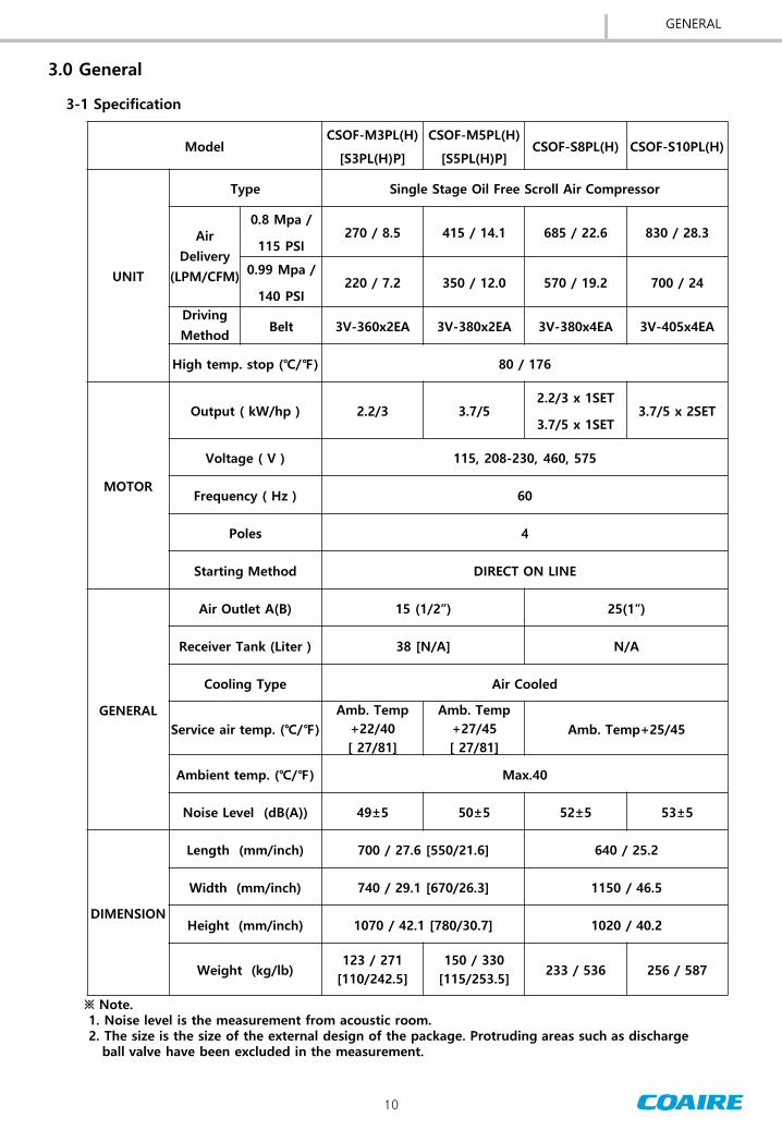
11
3-2 Major Component
3-2-1 CSOF-S3PL(H)P CSOF-S5PL(H)P
[ Fig3-1 ] Rear View
[ Fig3-2 ] Front View
DESCRIPTION
1 COMMON BASE
2 COVER amp FRAME
3 AIREND
4 MOTOR
5 MOTOR PULLEY
6 AIREND PULLEY
7 SUCTION FILTER
8 AIR DELIVERY PIPE
9 AIR DISCHARGE PIPE
10 AIR COOLER
11 COOLING FAN
12 CONTROLLER
13 CONTROL BOX
14 V-BELT
15 CHECK VALVE
16 SAFETY VALVE
17 DRAIN VALVE
18 PRESSURE TRANSMITER
111
2
7
8
12
13
15
3
4
5
6
9
10
14
16
17
18
GENERAL
12
12
13
1
10
11
5
14
6
2
3
7 4
8
18
17
15
16
9
19
3-2-2 CSOF-M3PL(H) CSOF-M5PL(H)
DESCRIPTION
1 COMMON BASE
2 COVER amp FRAME
3 AIREND
4 MOTOR
5 MOTOR PULLEY
6 AIREND PULLEY
7 SUCTION FILTER
8 AIR RECEIVER TANK
9 AIR DELIVERY PIPE
10 AIR COOLER
11 COOLING FAN
12 CONTROLLER
13 CONTROL BOX
14 V-BELT
15 CHECK VALVE
16 SAFETY VALVE
17 DRAIN VALVE
18 PRESSURE TRANSMITTER
19 EMERGENCY SWITCH [ Fig3-3 ] Outline View
[ Fig3-5 ] Rear View [ Fig3-4 ] Front View
GENERAL
13
1
13
2
2
3
4
5
6
7
89
10
11
12 19
14
15
16
17
18
3-2-3 CSOF-S8PL(H) CSOF-S10PL(H)
[ Fig3-8 ] Rear View [ Fig3-7 ] Right View
DESCRIPTION
1 COMMON BASE
2 COVER amp FRAME
3 AIREND
4 MOTOR
5 MOTOR PULLEY
6 AIREND PULLEY
7 SUCTION FILTER
8 AIR DELIVERY SOCKET
9 AIR DELIVERY PIPE
10 AIR COOLER
11 COOLING FAN
12 CONTROLLER
13 CONTROL BOX
14 V-BELT
15 CHECK VALVE
16 SAFETY VALVE
17 DRAIN VALVE
18 PRESSURE TRANSMITTER
19 EMERGENCY SWITCH [ Fig3-6] Left View
GENERAL
14
3-3 System Diagram
3-3-1 CSOF-M(S)3PL(H)(P) CSOF-M(S)5PL(H)(P)
The CSOF Series are an oil-free scroll air compressor In an operation a main motor is run to
initiate the compression at an airend The external air is filtered through a suction filter before
entering into the airend The compressed air is stored into an air tank via a check valve (non-return
valve) The temperature of the compressed air discharged from the airend is at least 200degC(392)
The air is primarily cooled in an air tank and secondarily via an air cooler before being discharged
The saturated vapor phase compressed air condenses into a water that can manually be discharged
via a drain valve in the air tank
There are following four safeguards in CSOF-M(S)3PL(H) and CSOF-M(S)5PL(H) models
1) Over Current Relay (OCR) for Motor ndash Detects the over current of the motor to stop the
compressor
2) Mechanical Safety Valve ndash Mechanically discharges the compressed air in the air tank to the
air if the air pressure exceeds the set value The compressor shall manually be stopped
3) Temperature Sensor (Temperature Transmitter ) ndash Detects the temperature exceeding the set
value (80degC176) at the bottom of the airend to stop the compressor
4) Pressure Sensor (Pressure Transmitter ) ndash Detects the pressure in the air tank and sends the
value to the controller to stop the compressor if the air pressure exceeds the set value
[ Fig3-9 ] System Diagram
GENERAL
CSOF-S35PL(H)P
CSOF-M35PL(H)
15
3-3-2 CSOF-S8PL(H) CSOF-S10PL(H)
[ Fig3-10 ] System Diagram
The basic principle of the CSOF-S8PL(H) and CSOF-S10PL(H) is equal to that of CSOF-M3PL(H)
and CSOF-M5PL(H) However the CSOF-S8PL(H) and CSOF-S10PL(H) have two airend to
sequentially be started up depending on the load to be used As there is no air tank in the
compressor a drain valve is used on the discharge end to drain the condensate water generated
during the compression For the CSOF-S8PL(H) or above an air receiver tank shall separately be
ordered and installed by the amount of air used The tank capacity varies depending on the load
to be used for example minimum capacity is 60 liters for the CSOF-S8PL(H) and 80 liters for the
CSOF-S10PL(H)
There are following four safeguards in CSOF-S8PL(H) and CSOF-S10PL(H) models
1) Over Current Relay (OCR) for Motor ndash Detects the over current of each motor to stop only the
motor failed
2) Mechanical Safety Valve ndash Mechanically discharges the compressed air in the air tank to the
air if the air pressure exceeds the set value The compressor shall manually be stopped
3) Temperature Sensor (Temperature Transmitter ) ndash Detects the temperature exceeding the set
value at the bottom of each airend to stop only the motor failed
4) Pressure Sensor (Pressure Transmitter ) ndash Detects the pressure in the air tank and sends the
value to the controller to stop the compressor if the air pressure exceeds the set value
GENERAL
16
40 Installation
[ Fig4-1 ] Name plate
4-2 Handling
4-2-1 Handling by a forklift
When handling by a forklift make sure that forks completely extend through the width of the unit (Fig4-2)
4-2-2 Handling by a shop crane
When handling by a shop crane use the openings provided on common base where slings or steel wire
ropes can be use for lifting (Fig 4-3)
[ Fig4-2 ] [ Fig4-3 ]
4-1 Inspection
When you receive the compressor please inspect it close
Upon received check the compressor damage carefully
during the transportation
If goods are received in damaged condition it is important
that you notify the carrier and insist on a notation of loss or
damage across the freight bill
INSTALLATION
17
4-3-2 Ventilation
4-3-1 Where to Install
Poor ventilation in the compressor room may raise the temperature of the air discharged
If the room temperature exceeds 10degC(18) more than the outside temperature sufficiently
Ventilate the air in the room(see Table 4-1) and install the exhaust duct if necessary
COAIRE air compressor is designed for the indoor use The ventilation facility and piping affect
the performance and the service life of the compressor Please follow the instructions in the userrsquos
manual
[ Fig4-4 ] Installation of the Air Compressor
MIN
1ft
MIN
32
8ft
MIN 492ft MIN 656ft
V=984fts below
V=164fts below
EMERGENCY
STOP
[ Fig4-5 ] Installation of the Exhaust Duct
FLEXIBLEHOSE
BALLVALVE
4-3 Installation
INSTALLATION
18
4-3-3 Selection of Where to Install
Item Description
Place - Do not install the compressor unit on the outside
- Please keep warm during the winter season if you have to install on the outside
Space
- Keep the space of more than 08m(263ft) from the wall to facilitate the repair
and maintenance of the compressor
- Do not place any object in front of the door
Floor and
Foundation
- The floor shall sufficiently holds the weight of the compressor
- The floor surface shall be flat with a gradient less than 1 degree to minimize
the vibration
- It is recommended to install the compressor 10cm(394rdquo) above the floor though
COAIRE air compressor generates an insignificant amount of vibration
Room
Temperature
- Optimal ambient temperature is 0-40degC(32~104) during the operation
- Install the compressor at low temperature and moisture if possible
Each 10degC(18) increase of the inlet temperature reduces the efficiency of the
compressor by 3-4
Hazardous
Substances
- Install the compressor at the place where there is the least noxious gas
hazardous substance and dust Those foreign substances may cause the damage
of the air compressor
Electricity - The electric power shall have at least 150 of the reference margin
- The range of fluctuation in voltage shall be within plusmn10
Ventilation
- A ventilation fan shall be installed to forcedly ventilate the room if the room
temperature exceeds 10degC(18) more than the outside temperature in the
summer
- For an exhaust duct set the velocity at 5 ms(164fts) and the static pressure at
less than 5 mmAq
- Install a protective net on the exhaust outlet to prevent birds rodents and
foreign substances from entering
- Place the inlet as low as possible
[table 4-2] Requirements for Where to Install
Model Air Volume
[CMM CFM ]
Hood Size
[ mm x mm ft x ft ]
CSOF-M3PL(H) CSOF-M5PL(H)
CSOF-S3PL(H)P CSOF-S5PL(H)P 30 1059 300 x 600 1 x 197
CSOF-S8PL(H) CSOF-S10PL(H) 60 2118 400 x 800 131 x 263
[ Table 4-1 ] Ventilation Fan Capacity
INSTALLATION
19
4-5 Wiring
1) Extremely low or high voltage power supply may cause the failure of the compressor Low power
capacity also causes significant voltage drop when starting up the compressor The compressor
requires at least 85 of the rated voltage for a start-up which shall be maintained within plusmn10 of
the rated voltage during the operation The inter-phase voltage imbalance shall be within 2 not
exceeding 3 even in a special case
2) Features and Capacity
See Table 4-4 Electrical Specification for an appropriate electric power an operating current and a
starting current Considering that the discharge air pressure abnormally exceeding the rated
operating pressure increases the operating current wiring shall allow about 120 of the rated
capacity of a main transformer
3) See Table 4-4 Electrical Specification for the electric power [kW] and the power factor []
4) Minimum Capacity of Transformer [kVA] = Electric Power [kW] Power Factor [] x 100 x 12
5) Longer lead-in wiring of the main power may cause the compressor failed or tripped during the
start-up due to the voltage drop in the line Select the thickness of the cable so that it maintains at
least minimum starting voltage
6) The calculation of the voltage drop based on the line length is as follows 3-Phase 3-Line Type Connection Where I = Current [A] A = Cross Section of Cable [mm2] e = Voltage Drop [V] L = Length of Cable [M]
4-4 Requirements for the Piping
1) Use a larger diameter and install the pipe without an excessive bending to reduce the pressure
drop
2) Always place a branch pipe on the top of a main pipe to reduce the discharge of oil or water
3) For the compressed air pipes reduce the number of sections bending and connecting and the
number of valves installed to reduce the pressure loss
4) The increased pressure loss requires a high discharge pressure of the air compressor
Consequently it causes the power loss The water stays wherever the pipe is sagging to increase
the pipe resistance which may cause winter-sowing Thus consider the pipe straightness when
installing the pipes
5) Install a bypass piping on each equipment for a maintenance
6) A scroll air compressor has a check valve in the system Installing more check valves between the
compressor and the air receiver tank may cause a malfunction of the compressor
7) Always install a drain valve on the bottom of a vertical pipe for the prevention of a winter-sowing
e = 308 x L x I
1000 x A
INSTALLATION
20
INSTALLATION
7) It is recommended that the thickness of the cable shall allow more than the minimum requirement
specified for a power condenser and the length of the cable shall be within 15m(492ft) No wiring is
necessary if there is a power condenser with a sufficient capacity in the bus conductor
8) Leave intact the factory specification of the overcurrent protection device If the change is unavoidable
keep the set values within the range specified in the userrsquos manual The cable shall allow more than the
minimum requirement specified
9) As the operating current varies depending on a given condition it is recommended to allow about 20
extra
10) Install a circuit breaker in the main power to protect the motor The circuit breaker shall have a built-in
electric leak breaker
11) Use the ground terminal on a motor or a control box to earth the equipment
[ Table4-3 ] MINIMUM COPPER EARTHING CONDUCTOR SIZE
Nominal size of active conductor(mm2)
Nominal size of copper earthing conductor
mm2
With copper active conductors
With Aluminum active conductors
1 1 -
15 15 -
25 25 -
4 25 -
6 25 -
10 4 -
16 6 4
25 6 6
35 10 6
50 16 10
70 25 10
95 25 16
120 35 25
150 50 25
185 70 35
240 95 50
300 ge120dagger 70
400 ge120dagger ge95dagger
500 ge120dagger ge95dagger
630 ge120dagger ge120dagger
These earthing conductors may be used only where incoporated in a multi-core cable of flexible cord other than a lift travelling cable in accordance with Clause 5334 (b) and (c) dagger A larger earthing conductor may be required to satisfy Clause 53311
21
[ Table 4-4 ] Electrical Specification
INSTALLATION
Caution
1) As the grounding on a steel structure of the building may cause the failure of the operation
always earth on the ground The maximum allowable length of the grounding conductor is
20m(655ft)
2) If there is a risk of inductive interference on an electronic calculator or a telecommunication
equipment install a surge killer on the magnetic switch used
3) The compressor has a complete wiring inside and no separate wiring or maintenance is necessary
If any maintenance is needed see the circuit diagram in the userrsquos manual provided with the
compressor
Model
Output Voltage Driving
MCCB OCR Main Power
Earth wire Current Cable
[kW] [V] [A] AF TRIP SET
AWG AWG [A] [A]
CSOF-M(S)3PL(H) (1PH)
22
115 32 50 50 384 8 10
230 16 30 30 192 12 12
CSOF-M(S)5PL(H) (1PH)
37 230 23 50 40 276 10 10
CSOF-M(S)3PL(H) (3PH)
22
208-230 87 8 30 15 104 96 16 12
460 4 30 10 48 18 12
575 33 30 10 40 18 12
CSOF-M(S)5PL(H) (3PH)
37
208-230 14 132 30 30 20 168 158 14 12
460 66 30 10 79 18 12
575 52 30 10 62 18 12
CSOF-S8PL(H) (3PH)
22 + 37
208-230 227 212 50 40 104 168 96 158
10 10
460 106 30 20 48 79 14 12
575 85 30 15 40 62 16 12
CSOF-S10PL(H) (3PH)
37x2EA
208-230 28 264 50 50 40 168 158 10 10
460 132 30 20 79 14 12
575 104 30 20 62 14 12
22
5-1 Commissioning ( Initial Operation )
50 Operation
5-1-1 Structure of the Controller
1) Check if the voltage of the main power is within a normal range specified
2) Cut the main power to connect the power line to the control panel
3) Check the connection of pipes a power supply and a grounding
4) Fully open a stop valve on the discharge pipe of the compressed air
5-1-2 Checklists before the Commissioning
5-1-3 Commissioning
1) Push the ldquoSTARTrdquo button on the controller to check the direction of rotation If it is operated in a
negative phase immediately push the emergency stop button turn the main power off and then
convert ldquoRrdquo into ldquoTrdquo before restarting When the compressor starts the pressure is increased in the
airend to start the compression
2) With the discharge valve closed on the discharge side of the air tank check if the compressor is
automatically stopped when the pressure reaches the set value
3) Check if there is any abnormal vibration noise and leakage
4) Push the ldquoSTOPrdquo button on the controller
OPERATION
[ Fig 5-1 ] Control Button
Reset Cancel Down Enter Up Menu
monitor
Start
Stop
23
[ Table 5-1 ] Operation Parameters
Section Model
CSOF-M3PL(H) CSOF-M5PL(H)
CSOF-S3PL(H) CSOF-S5PL(H)
CSOF-S8PL(H) CSOF-S10PL(H)
Setting Pressure MPa psi 08 115 099 140
Difference
Pressure MPa psi
Stop 08 115 099 140
Re-start 06 92 079 117
High temp stop 80 176 ( Airend )
Starting Method DOL
5-2 Routine Operation
5-2-1 Checklists before the Operation
1) Connect the main power to check the display on the monitor
2) Push the ldquoSTARTrdquo button on the controller to check if the compressor is well started up and the
indicator lamps are normally on
3) Check if there is any abnormal vibration noise and leakage
4) Check if the operation is in good condition at the maximum load
Check the following conditions before starting the operation
Discharge Pressure
Comp Temp
Alarm Message
Lock Symbol
Operate Status
Target Pressure
OPERATION
[ Fig 5-2 ] Controller Display
24
5-2-2 Start-Up
1) Check if the tank pressure is 0 Mpa(0 psi)
2) Check if the monitor indicates a normal condition for the operation and then push the ldquoRUNrdquo button
3) Fully open the valve on the discharge side before starting the compressor
4) Check if there is any abnormal noise and the operation is in good condition
5-2-3 During the Operation
1) With a full load check the values indicated by the instruments Also check if the indicator lamps are
normally on in the control panel
2) Pull the ring on the safety valve every 500 hours to check if the operation is normal
[ Table 5-2 ] Checklists During the Operation
1) Push the ldquoSTOPrdquo button
2) Turn the main power off
3) Check if the internal pressure is completely discharged from the compressor
5-2-4 Stop
Regularly record the information about the operation events in the operation log to early find the failure
of the compressor and to prevent the accident before happens The information includes the discharge
pressure operating time maintenance items and the time to replace the parts There is a sample
operation log attached in the userrsquos manual
5-2-5 Operation Log
1) It is extremely hazardous to disassemble the valves or pipes from the compressor system during
the operation
2) Always check if the pressure is 0 Mpa(psi) in the tank before disconnecting the valves or pipes
3) Since the tank is still hot for a certain time even after the operation is stopped there is a danger
of burns if you are not careful
4) The rotating parts in the compressor is extremely dangerous during the operation
Do not come near the parts until the compressor is stopped and the main power is turned off
Warning
OPERATION
Section Regulation Re-mark
Airend Temp Max80 176(Airend)
Amb Temp 0~40 32~104 Inhibit under -10 (14)
Lamp on during the operation RUN
Input voltage plusmn10 of rated voltage
Pressure gap of unit and discharge Max 005 Mpa 0725 psi
Condensate water must be removed from receiver tank everyday If the condensate water is not
drained off then compressed air contains moisture which will cause damage to the equipment or
parts breakdown COAIRE will not compensate loss incurred by consumers fault
25
6-1 Airend
60 Functional Descriptions
[ Fig6-2 ] Motor
Sirocco Fan
Fixed Scroll
Orbiting Scroll
Fan Cover
Housing
Tip Seal
[ Fig6-1 ] Airend parts
6-2 Motor
An oil free scroll airend is the most important part in the compressor In any case the oil is not
entered into the compression chamber As the inside of the compression chamber is delicate entering
the dusts or foreign substances results in a serious damage to the compressor The airend consists of
precision parts and needs a special jig for a repair and maintenance It shall only be disassembled by
our qualified engineer or a comparable person
Some models of the scroll air compressor are equipped with
several motors for an automatic operation based on the amount
of air used The motor is a 3-phase induction motor that has
a service factor higher than a general motor and is designed to
generate a high efficiency suitable for an air compressor
The motor plays an important role for the operation of the air
compressor and needs maintenance on a regular basis
FUNCTIONAL DESCRIPTIONS
26
[ Fig 6-6 ] CHECK VALVE
6-3 Fan
[ Fig6-5 ] SUCTION FILTER
6-5 Suction Filter
6-6 Check Valve
Fan is key part to keep proper temperature of airend please
keep clean and periodically remove dust and foreign object not
to dysfunction
An airend consists of precision parts that need a clean air to be
used for an optimal service life COAIRE air compressor is
equipped with a paper suction filter that has 999 of the
dedusting efficiency The filer needs to be replaced every 2000-
3000 hrs If it is unavoidable circumstance the reuse is only
allowed once after cleaning
Make sure to use only the genuine COAIRE suction filter
A check valve plays an important role in the scroll air compressor
The valve prevents the backflow of the compressed air when the
compressor is stopped to protect the compressor from damaging
due to a back-lashing The valve also protects the wrap of the
compressor from damaging due to foreign substances back flown
from the pipe to the compressor The valve is designed to stand
against a repetitive pulse motion of scroll at a high temperature
200degC (392)or above
[ Fig6-4 ] COOLER
[ Fig6-3 ] FAN
A cooler element is an aluminum cooler that is designed to be used up to 15 Mpa(215psi) Dust may
increase the temperature in the cooler pin which needs to be cleaned with the compressed air or a
detergent on a regular basis When cleaning cover the electric parts to keep the water out
6-4 Cooler
FUNCTIONAL DESCRIPTIONS
CSOF-M3PL(H)P CSOF-M5PL(H)P CSOF-S35PL(H) CSOF-S810PL(H)
27
1) Power Supply AC24V plusmn15 5060Hz 40w
2) Transformer Capacity Min 50[VA]
3) Operating Temperature -10 ~ 60 ( 14 ~140 )
4) Operating Moisture 95 40(104)
5) Storage Temperataure -30 ~ 80 ( -22 ~176 )
7-2 Major Functions
[ Fig7-1 ] Display of the Controller
7-2-1 Display
70 Control
7-1 Controller
COAIRE air compressor uses a controller based on a microprocessor for an optimal operation of the
compressor The controller is a system that precisely determines the time to adjust the capacity to save the
energy gives an alarm to prevent the accident before happens and notifies the information necessary for
repair and maintenance The system ensures the best automatic operation optimized by the set conditions
and the machine conditions
7-1-1 Operating Conditions
Discharge Pressure
Comp Temp
Alarm Message
System Locked Symbol
Operate Status
Target Pressure
CONTROL
28
STRAT STOP
Enter started conditionExit started condition
RESET Reset and clear fault condition
MENU Enter to Menu table
ENTER Confirm selection of value adjustment
UP DOWN Scroll updown through menu menu item options or incrementdecrement value
CANCEL Step back one menu navigation level
7-3 Configuration of functions
[ Fig7-2 ] Keypad of Controller
[ Table 7-1 ] Description of Keypad
CONTROL
29
NOTE
1) ON illuminated continuously
2) SF slow flash onoff once per second
3) FF fast flash onoff five times per second
4) IF Intermittent Flash onoff every four seconds
5) OFF Extinguished continuously
STATUS LED Green Display working status along ON OFF
FAULT ALARM LED Red Display fault or alarm status along ON OFF
Machine
state Number Machine state Status( Green ) Fault ( Red )
00 Initialization OFF
Normal OFF
Trip FF
Alarm SF
Maintenance IF
Start Inhibit IF
01 Start Inhibit
Check OFF
02 Ready to Start OFF
03 Start Delay
IF
if load request FF
04 Standby IF
06 Start Motor in
star Delta
IF
if load request FF
07 Load Delay
IF
if load request FF
08 Load ON
09 Reload Delay
IF
if load request FF
10 Auto stop delay IF
11 Manual stop
delay SF
99 Shut down OFF
7-3-1 Status Display Ramp
CONTROL
30
7-3-3 Equipment Status Display
CONTROL
7-3-3 Equipment Status Display
SYSTEM LOCKED SYMBOL
7-3-4 System Locked
1 STARTSTOP REQUEST SOURCE DISPLAY
LOC Controller keyboard
NET Communication request
REM Digital inputs
2 LOAD REQUEST SOURCE DISPLAY
PRE Pressure sensor
NET Communication request (Option)
REM Digital inputs
3 STOP STATUS DISPLAY
Display while compressor stopped
LOC STP Stopped by controller keyboard
REM STP Stopped by digital inputs
NET STP Stopped by communication request (Option)
SD STP Stopped by fault condition
4 START STATUS DISPLAY
Display while compressor started
LOC RUN Started by controller keyboard
REM RUN Started by digital inputs
NET RUN Started by communication request (Option)
5 COMPRESSOR STATUS DISPLAY
GOOD Normal condition
MAINTEN Maintenance required
ALARM Alarm condition
S-DOWN Trip condition
INHIBIT Start inhibit condition
7-3-5 Digital Input Symbols
Symbol Description Remark
DI1 Over-load Main Motor 1 fault (open)
DI2 Over-load Main Motor 2 fault (open)
DI4 Emergency Switch fault (open)
DI5 Remote StartStop Control Run (closed)
DCM INPUT fault (open)
31
CONTROL
7-3-6 Digital Output Symbols
Symbol Description Description
N1 Compressor 1 Main Magnetic Contactor On
N2 Compressor 2 Main Magnetic Contactor On
NC1 N1 N2
N4 Run On
N5 Alram On
NC2 N4 N5
7-3-7 Menu structure and navigation
[Fig7-3 ] Menu structure and navigation
Main Menu Select
Sub Menu Select
Parameter Adjustment
32
CONTROL
7-3-8 Menu level
ACCESS LEVEL USER (CODE = 0000) SERVICE 1 (CODE = 0100)
ACCESS-ABLE MENU
00 STATUS MODE 01 PRESSURE MODE 02 SCHEDULE MODE 03 TRIP LOG MODE 04 TRIP SET 05 OPERATION SET 06 COMP SET 07 CONFIG MODE
00 STATUS MODE 01 PRESSURE MODE 02 SCHEDULE MODE 03 TRIP LOG MODE 04 TRIP SET 05 OPERATION SET 06 COMP SET 07 CONFIG MODE 08 FACTORY SET
TIMEOUT PERIOD 1 MINUTE 10 MINUTE
Press ldquoMENUrdquo button for a seconds in status mode an access code entry display (Fig 7-4) is shown
Use ldquoPLUSrdquo button to adjust value then press ldquoENTERldquo button If the access code have been entered to
authorized menu page will be displayed An invalid code will return the display to normal operation mode
[ Fig7-4 ] ACCESS CODE ENTRY DISPLAY
NOTE
1) When access level is ldquoSERVICE 1rdquo [Equipment Environment Setup] menu cannot be adjusted
2) Press ldquoCANCELrdquo button for three seconds at any time to return to the system locked condition
33
CONTROL
ACCESS CODE ( 0100 ) Editable
M
E
N
U
S
T
R
U
C
T
U
R
E
1 STATUS MODE times
2 PRESSURE MODE
- TARGET PRESSURE
- STEP1~STEP8 RUNPRESS
- STEP1~STEP8 STOPPRESS
- LCD LIGHT MODE
times
times
times
3 SCHEDULE MODE times
4 TRIP LOG MODE times
5 TRIP SET times
6 OPERATION SET times
7 COMP SET times
8 CONFIG MODE times
7-3-9 Digital output
7-4 Error messages
7-4-1 TRIP ALARM MESSAGE
Item Description Detect condition
1 System Error Parameter Error
2 Emergency stop Push the emergency stop switch
3 Press Sensor Fault Low Resistance Short Circuit Short Circuit to Earth
4 Delivery Pressure High Detection Pressure gt= [ DIS PRESS LIMIT] Reset Pressure lt [ DIS PRESS LIMIT ndash 05bar(-725psi)]
5 Comp 1 Fault Detection [Digital Input ID1 ] OPEN Reset [Digital Input ID1] CLOSE
6 Comp 2 Fault Detection [Digital Input ID2 ] OPEN Reset [Digital Input ID2] CLOSE
7 Comp 1 Temp Detection Comp1 Temp gt= [COMP TEMP LIMIT] Reset Comp1 Temp gt= [COMP TEMP LIMIT- 5(-9)]
8 Comp 2 Temp Detection Comp2 Temp gt= [COMP TEMP LIMIT] Reset Comp2 Temp gt= [COMP TEMP LIMIT- 5(-9)]
An trip message is displayed that must be manually reset to clear once the condition has been resolved or no longer exists
7-4-2 Alarm condition
Item Description Detect condition
1 RTC(Real Time Clock) Alarm Detection RTC Disable (When Schedule Mode Operation) Reset RTC Enable
An trip message is displayed that will be automatically reset to clear once the condition has been resolved
34
CONTROL
7-4-3 Event massage for operation information
Item Description Detect condition
1 1rsquoST POWER The time when Initial Power UP to Controller
2 POWER UP The time when power up to controller System restoration by watchdog timer
3 START The time when motor started
4 STOP The time when motor stopped
7-4-4 Maintenance Message
ITEM DETAIL
MAINTENANCE INTERVAL (Hour) Remark
80 bar 99 bar
IN FILTER CHG Occurred When maintenance interval is expired 2500 2500
Alarm Status
BELT TS CHECK Occurred When maintenance interval is expired 2500 2500
SEAL CHANGE Occurred When maintenance interval is expired 9000 4000
CHECK VV CHG Occurred When maintenance interval is expired 9000 9000
SEAL CHG TRIP Occurred When maintenance trip interval is expired 1000 1000 Trip Status VV CHANGE TRIP Occurred When maintenance trip interval is expired 1000 1000
1) When maintenance interval of alarm is expired ldquoSERVICE ALrdquo message is displayed on controller
and alarm or trip is occurred
2) When maintenance interval of trip is expired ldquoSERVICE TRIPrdquo message is displayed on controller and
alarm or trip is occurred
3) When CHANGE and CHECK interval are expired alarm is occurred
4) When SEAL CHG TRIP interval is expired after SEAL CHANGE alarm occurred trip is occurred
5) When VV CHANGE TRIP interval is expired after CHECK VV CHANGE alarm occurred trip is occurred
6) ldquo 00h AF TRIPrdquo is displayed on controller since 99 hours before each CHANGE TRIP interval expirer
7) When maintenance message occurs type of alarm or trip can be checked on TRIP LOG menu
8) When maintenance alarm or trip occurs alarm or trip must be released by changing the setting after
check or change of corresponding part
35
80 Maintenance
MAINTENANCE
Check repair Replace
8-1 Scheduled Maintenance ndashLOW PRESSURE 08 MPa(115psi) (Model CSOF- P L )
Maintenance should be followed below table
Section Action Taken
Times Interval Remarks
Every day
500hr 2500hr 5000hr 10000hr 20000hr
2 month 1 year 2 years 4 years 8 years
Water Drain Drain out
Suction Filter Clean Replace
exchange
in case of contamination
Airend fan Clean
Airend grease Re-grease
Use gunuine parts
Tip seal Replace
Dust seal Replace
Belt Check Replace
(first)
Loose tension causes noise
Temp sensor Check operation Replace in case
of abnormal operation
Pressure Sensor Check operation
Safety VV Check operation
Check VV Check Replace
Use gunuine
parts
Ventilation fan Check
Replace in case of abnormal operation
Magnetic contactor
Check Replace
Motor Check insulation
bearing
Suction hose Replace
After cooler Clean
exchange
in case of contamination
Control panel Check monitor
Piping Check leak
Airend Overhaul
Control box Clean
Check bolt
NOTE Maintenance schedule is instructed above The intervals are a guide based on normal operating conditions If operated in a severe environment necessary maintenance service should be performed on a more frequent basis User should carry out the maintenance work based on either the running hours or the calendar time whichever comes first
36
MAINTENANCE
NOTE Maintenance schedule is instructed as above The intervals are a guide based on normal operating conditions If operated in a severe environment necessary maintenance service should be performed on a more frequent basis User should carry out the maintenance work based on either the running hours or the calendar time whichever comes first
Check repair Replace
8-2 Scheduled Maintenance ndashHIGH PRESSURE 099 MPa(140psi) (Model CSOF- P H )
Maintenance should be followed below table
Section Action Taken
Times Interval Remarks
Every day
500hr 2500hr 5000hr 10000hr 20000hr
2 month 1 year 2 years 4 years 8 years
Water Drain Drain out
Suction Filter Clean Replace
exchange
in case of contamination
Airend fan Clean
Airend grease Re-grease
Use gunuine parts
Tip seal Replace
Dust seal Replace
Belt Check Replace
(first)
Loose tension causes noise
Temp sensor Check operation Replace in case
of abnormal operation
Pressure Sensor Check operation
Safety VV Check operation
Check VV Check Replace
Use gunuine
parts
Ventilation fan Check
Replace in case of abnormal operation
Magnetic contactor
Check Replace
Motor Check insulation
bearing
Suction hose Replace
After cooler Clean
exchange
in case of contamination
Control panel Check monitor
Piping Check leak
Airend Overhaul
Control box Clean
Check bolt
37
[ Fig8-1 ] Scroll Airend
[ Fig8-2 ] Vertical CSOF-M3PL(H)(P) CSOF-M5PL(H)(P)
[ Fig8-3 ] Horizontal CSOF-S8PL(H) CSOF-S10PL(H)
8-3 Maintenance
8-3-1 Regular Maintenance of the Airend
1) Check if there is any abnormal vibration or noise during a routine
operation and contact the nearest distributor if necessary
2) There are two types of the scroll airend Low Pressure (08 Mpa
115psi) and High Pressure (099MPa 140psi) The maintenance
period is different by type specified in the identification plate
attached on an airend The standard specification of COAIRE airend
is a low pressure type
3) Periodically lubricate an airend with grease See the maintenance
schedule for when the lubrication is needed
The airend consists of precision parts and needs special tool and jig for a repair and maintenance
It shall only be disassembled by our qualified engineer Contact the nearest distributor if necessary
Caution
8-3-2 Rotation of the Driving Part
If the motor is not started up or generates an abnormal noise stop the compressor turn the main
power off and then manually rotate the motor pulley If it does not rotate smoothly contact the
nearest distributor for a service It is mostly due to the damage on the motor bearing or when the
airend is stuck
Warning
An air compressor is automatically operated Do not come near the parts until the compressor is
stopped and the main power is turned off It may cause a serious personal injury if hair or clothes is
caught in the rotating parts
MAINTENANCE
38
[ Fig8-5 ] Belt align - CSOF-S8PL(H) CSOF-S10PL(H)
Adjust the belt tension in first 500 hrs after the purchase and every 3000 hrs (6 months) thereafter
in the following procedures
8-3-3 Adjustment of the Belt Tension
1) Use a tensiometer to measure the displacement of each belt
2) Loose the anchor bolt on the motor base and use the tension adjusting bolt to adjust the tension
with reference to the [Table 8-1]
3) Align the motor and tighten the anchor bolt on the motor base
Off-centered pulleys generate the noise and vibration and accelerate the process of wearing the belt
and pulley to cause the damage to the belt Align the center of the pulley during the replacement of a
belt and the adjustment of the belt tension With the compressor fixed loose the anchor bolt on the
motor and place an iron rule between the pulleys as shown in the following fig Gradually tighten the
anchor bolt on the motor and check the center is aligned between the pulleys Completely tighten the
bolt recheck the alignment and then rotate the pulley to check if the belt moves smoothly
8-3-4 Alignment of the Belt
MAINTENANCE
[ Table 8-1 ] Belt tension
[ Fig8-4 ] Belt tension check
Looseness = δ [mminch]
P [ kglbs] Model
New Displace
P (kglbs)
Δ (mminch)
P (kglbs)
Δ (mminch)
3HP HORIZON
1533 65 026rdquo 1329 64 025rdquo
5HP HORIZON
1738 6 023rdquo 1635 58 022rdquo
3HP VERTICAL
1533 5 019rdquo 1329 5 019rdquo
5HP VERTICAL
1738 5 019rdquo 1635 5 019rdquo
FIXED SIDEADJUSTED SIDE
AIRENDMOTOR
Belo
w 1
00
4(
mm
inch)
39
[ Fig8-8 ] Suction filter cleaning
[ Fig8-6 ] Belt Align ndash CSOF-M3PL(H)(P) CSOF-M5PL(H)(P)
[ Fig8-7 ] Belt Tension Settle-CSOF-M3PL(H)(P) CSOF-M5PL(H)(P)
1) An air compressor is automatically operated Do not check and replace the belt until the
compressor is stopped and the main power is turned off
2) Only use the belt specified by COAIRE for a replacement Do not use old and new belts mixed and
replace the entire set of belts all at once
3) The shaft is damaged and the service life of the bearing is shorten at a high tension of the belt
while the belt is slippery at a low tension of the belt Always keep the optimal tension value with
reference to the [Table 8-1]
Caution
8-3-5 Cleaning the Suction Filter
1) Check the contamination level every 500 hrs
2) Replace the heavily contaminated filter even before the
replacement period
3) Blow the element with the compressed air outward and
then by the side
4) Keep dust and foreign substances out of the compressor
during the assembly
Caution
A suction filter significantly affects the service life of an airend Make sure to use only the genuine
COAIRE suction filter COAIRE cannot be responsible for any damage caused by an improper
replacement
MAINTENANCE
Below 1mm(004)
FIXED SIDE
ADJUSTED SIDE
AIREND
MOTOR
40
9-1 Overview
90 Troubleshooting
The following flow diagrams show the procedures to repair the typical failures If the alarm is on and
the compressor is stopped do not restart the operation until the cause is clearly addressed and
eliminated Always turn the main power off and remove the pressure from the compressor prior to a
repair and maintenance
9-2 Flow Diagram for Troubleshooting
9-2-1 No Display
Negative-phase operation
Poor connection to power supply
Convert the phase for two of three main power lines
Abnormal noise
Start-Up Request a service
No Display
Poor connection to power supply
Yes
No
- Check the breaker switch
- Check the wiring
Yes
Failure of
controller
- Check the fuse
- Check the transformer
- The controller is defective
Yes
Start-Up Request a service
9-2- 2 Negative-Phase Operation
No
No
After eliminating the
cause
After eliminating the
cause
TROUBLESHOOTING
41
Unable to start motor
Lead-in wiring is disconnected
- Check the resistance of incoming line
- Test wiring and cable capacity and replace the cable if necessary
Yes
No
9-2-3 Unable to Start Motor
Failure of magnetic switch
- Test wiring
- Check the contact and operation
and replace the switch if necessary
Yes
Failure of motor
Check the error message on the controller
- Take necessary action to correct the error
- Check the tripping error No
Yes
- Test wiring and resistance
- Manually turn to check the bearing
- Replace the motor if necessary
Yes
No
Failure of compressor
No
- Manually turn to check the rotation
- Request a service if it is defective
Failure of controller
- Check the output signal of the magnetic switch
- Turn the main power off and then on
Yes
Yes
No
Start-Up Request a service
No
1) An air compressor is automatically operated Take necessary safety precaution to ensure that the
compressor is not unintentionally operated during the maintenance
2) Make sure to turn the main power off prior to the rotation test
3) Make sure to turn the main power off prior to the wiring test except for the measurement of the
voltage
Danger
After eliminating the cause
TROUBLESHOOTING
42
Low discharge pressure
- Clean the suction filter and replace if necessary
No
9-2-4 No Compression
Airend is damaged
- Check the rotation
- Check if there is any abnormal noise
Yes
Failure of controller
- Check the pipe for leakage
- Install an additional compressor if the capacity is insufficient
No
Yes
- Check the function of a multi-unit control
- Check the magnet and the output of the controller
Yes
No
Start-Up Request a service
No
9-2-5 Discharge Pressure Rise
Discharge Pressure Rise Error message ldquoHigh pressurerdquo appears
Check the operation of the pressure sensor
No
Yes
Failure of controller Check the output of the controller
No
Failure of pressure sensor
Safety valve is activated
Pressure sensor or safety valve is defective
Yes
No
Start-Up Request a service
Excessive amount of air used
Yes
Suction filter is clogged
Yes
After eliminating the cause
After eliminating the cause
TROUBLESHOOTING
43
9-2-6 Discharge Temperature Rise
Discharge temperature rise Error message ldquoHigh temprdquo appears
Start-Up Request a service
Check the controller
- Check the inputout of the temperature sensor
- Replace the temperature sensor if necessary
Yes
High ambient temperature
- Keep the internal temperature 40degC (104) or below
- Check the ventilation facility and duct
Yes
No
No
1) An appropriate temperature of an airend is 70degC(158 ) or below at the operating temperature
40degC(104) or below
2) Always take necessary action if the temperature of the airend is sharply increased with no
change in ambient temperature
Notes
9-3 Other Troubleshooting
Trouble Cause Action
1 Tripped due to
the over current
in motor
1) Compressor is tripped
- Foreign substance in the compressor
- Damage to the wrap of the compressor
- Low voltage
2) Open-phaseUnbalanced power supply
3) Deteriorated coil in the motor
4) Failure of EOCR
1) Contact the distributor
- Improve the power supply
2) Improve the power supply
3) Check the motor
4) Readjust or replace
2 Noise and
Vibration
1) Fixing bolts are loose
2) Noise from the compressor
- Bearing is worn out or damaged
- Foreign substance in the compressor
3) Improper belt tension and the damage
to the parts
4) Inadequate installation of the compressor
5) Failure of cooling fan (dust or damaged)
1) Readjust
2) Contact the distributor
3) Realign or replace the belt
4) Reinstall the compressor
5) Clean or replace the fan
After eliminating the cause
TROUBLESHOOTING
44
10-1 CSOF-S3PL(H)P CSOF-S5PL(H)P
100 Outline drawings
OUTLINE DRAWINGS
MAIN POWER30 HOLE
AIR OUTLET
PS 15A(PT 12)
정 기 점 검
25 [
09
843]
DRAIN HOLE12 HOLE
토 출 공 기 구
100 [
39
37]
50 [19685]
80 [31496]
217 [85433] 208 [8189]
92 [
36
22]
130 [
51
181]
550 [216535]
150 [59055]200 [7874]
150 [59055]25 [09843]
60 [
23
602]
720 [
283
484]
780 [
307
087]
550 [216535]
670 [
263
781]
115 [
45
276]
30 [11811]
45
10-2 CSOF-M3PL(H) CSOF-M5PL(H)
OUTLINE DRAWINGS
WATER DRAIN (14)
AIR DISCHARGE (12)
640 [252]
700 [2756]
POWER IN
CONTROLLER
EXHAUST AIR OUTLET(COOLING FAN)
EXHAUST AIR OUTLET(SIROCCO FAN)
166 [654] 118 [465]
57 [224] 28 [11]
153 [60
2]
301 [118
5]
213 [83
9]
25 [09
8]
1505
[59
3]
260 [102
4]
100 [394]
740 [2913]
1070 [421
3]
EMERGENCY
STOP
46
10-3 CSOF-S8PL(H) CSOF-S10PL(H)
OUTLINE DRAWINGS
EXHAUST AIR OUTLET
AIR OUTLETPS 25A(PS1)
215 [846]200 [787] 320 [126] 200 [787]
1150 [4528]
75 [295]
225 [88
6]
AIR INTLET118 [46
5]
40 [15
7]
122 [48]376 [148]
166 [65
4]
169 [665]221 [87]560 [220
5]
640 [252]
MAIN POWER INLET
160 [63
]
1020 [401
6]
EMERGENCY
STOP
47
110 Electrical wiring drawings
11-1 CSOF-M35PL(H) CSOF-S35PL(H)P 230V460V575V
ELECTRICAL WIRING DRAWINGS
1
PR
IMAR
Y
IN
PU
T V
OLTAG
E
SEC
ON
DAR
Y
110V (
100VA)
NO
TES
51C
OVER C
URREN
T R
ELAY F
OR M
C
MC
MO
TO
R F
OR C
OM
PRESSO
RTR
TRAN
SFO
RM
ER
ESP
EM
ERG
EN
CY S
TO
P P
USH
SW
ITC
HM
VM
OTO
R F
OR V
EN
TIL
ATIO
N F
AN
CP
CIR
CU
IT P
RO
TEC
TO
RN
FN
OIS
E F
ILTER
TH
TH
ERM
ISTO
RPT
PRESSU
RE T
RAN
SM
ITTER
DESC
RIP
TIO
N
52C
MAG
NETIC
CO
NTAC
TO
R F
OR M
C
SK
SU
RG
E K
ILLER
WIR
ING
NU
MB
ER
PR
IMAR
Y
IN
PU
T V
OLTAG
ESEC
ON
DAR
Y
110V
52C
51C
48
11-2 CSOF-S8PL(H) CSOF-S10PL(H) 230V460V575V
ELECTRICAL WIRING DRAWINGS
PRIM
ARY
IN
PU
T V
OLTAG
E
51C
OVER
CU
RR
EN
T R
ELAY F
OR
MC
MC
MO
TO
R F
OR
CO
MPR
ESSO
RTR
TR
AN
SFO
RM
ER
ESP
EM
ER
GEN
CY S
TO
P P
USH
SW
ITC
HM
VM
OTO
R F
OR
VEN
TIL
ATIO
N F
AN
CP
CIR
CU
IT P
RO
TEC
TO
RN
FN
OIS
E F
ILTER
TH
TH
ER
MIS
TO
RPT
PR
ESSU
RE T
RAN
SM
ITTER
DESC
RIP
TIO
N
52C
MAG
NETIC
CO
NTAC
TO
R F
OR
MC
SK
SU
RG
E K
ILLER
WIR
ING
NU
MB
ER
SEC
ON
DARY
110V
49
11-3 CSOF-M35PL(H) CSOF-S35PL(H)P 1PH 230V
1
PRIM
ARY
IN
PU
T V
OLTAG
E
SEC
ON
DARY
110V (
100VA)
NO
TES
51C
OVER C
URREN
T R
ELAY F
OR M
C
MC
MO
TO
R F
OR C
OM
PRESSO
RTR
TRAN
SFO
RM
ER
ESP
EM
ERG
EN
CY S
TO
P P
USH
SW
ITC
HM
VM
OTO
R F
OR V
EN
TIL
ATIO
N F
AN
CP
CIR
CU
IT P
RO
TEC
TO
RN
FN
OIS
E F
ILTER
TH
TH
ERM
ISTO
RPT
PRESSU
RE T
RAN
SM
ITTER
DESC
RIP
TIO
N
52C
MAG
NETIC
CO
NTAC
TO
R F
OR M
C
SK
SU
RG
E K
ILLER
WIR
ING
NU
MB
ER
PR
IMARY
IN
PU
T V
OLTAG
ESEC
ON
DAR
Y
110V
52C
51C
ELECTRICAL WIRING DRAWINGS
50
11-4 CSOF-S8PL(H) CSOF-S10PL(H) 1PH 230V
ELECTRICAL WIRING DRAWINGS
PRIM
ARY
IN
PU
T V
OLTAG
E
51C
OVER
CU
RR
EN
T R
ELAY F
OR
MC
MC
MO
TO
R F
OR
CO
MPR
ESSO
RTR
TR
AN
SFO
RM
ER
ESP
EM
ER
GEN
CY S
TO
P P
USH
SW
ITC
HM
VM
OTO
R F
OR
VEN
TIL
ATIO
N F
AN
CP
CIR
CU
IT P
RO
TEC
TO
RN
FN
OIS
E F
ILTER
TH
TH
ER
MIS
TO
RPT
PR
ESSU
RE T
RAN
SM
ITTER
DESC
RIP
TIO
N
52C
MAG
NETIC
CO
NTAC
TO
R F
OR M
C
SK
SU
RG
E K
ILLER
WIR
ING
NU
MB
ER
SEC
ON
DARY
110V
STARTUP REPORT Please fill out completely and return to the factory to validate warranty
CUSTOMER AND MACHINE INFORMATION
CUSTOMER FACTORY SHIP DATE
ADDRESS DATE STARTED UP
CITYSTATE MODEL NUMBER PHONE SERIAL NUMBER WRITTTEN BY HOURS ON MACHINE Hrs
MACHINE INFORMATIONS AND INITIAL STARTUP
Compressor Environment- excellent good fair poor
Machine Location ndash indoors outdoors
if outdoors protected from rain Yes No
Approx ambient temperature______ adequate ventilation - Yes No
Did you check for correct rotation Yes No
Nameplate amperage for voltage used ______
Incoming Voltages
L1-L2 L2-L3 L1-L3
Volts Volts Volts
Full load amperage at _________ PSIG
L1 L2 L3
Amp Amp Amp
Unload amperage at _________ PSIG
L1 L2 L3
Amp Amp Amp
Is the machine on a level and stable surface Yes No
Was a flexible connector used to connect piping ndash Yes No
Approx time spent during startup procedure ___________ Hrs
Did you advice customer on operation and maintenance of machine Yes No
Application and installation comments
___________________________________________________________________________________________________
Machine Sold By(Company) __________________ Sales Person ___________________________ Startup performed by _______________ Date _________________________________
THERE IS NO WARRANTY WITHOUT THIS REPORT
Warranty Claim Report Please complete the following claim form your claim will be confirmed by our sales representative
To Coaire Division of Quietside 8750 Pioneer Blvd Santa Fe Springs CA 90670 Tel(562)576-1330Fax(562)699-4351 email supportcoairecom
Distributor
Company Date
Address Model
Serial No
Customer
Company Run Hours Hrs
Address Setting Press PSIG
OPERATING CONDITIONS Percent() on load Ambient Temperature F No of days of operation weekly Days Discharge temperature F Hours per day Hours Compressor area temperature F Machine setting OLOL or Mod Environment 1)
1) 1 to 10 1 being clean 10 very dirty
Incoming Voltages Full load amperage at _______ PSIG Unload amperage at ______ PSIG
L1 - L2 L2 - L3 L1 - L3 L1 - L2 L2 - L3 L1 - L3 L1 - L2 L2 - L3 L1 - L3
Volts Volts Volts Amp Amp Amp Amp Amp Amp
Symptom
Fault Diagnosis
Resolution
Parts required Labor Cost No Item Number DescriptionMFGR Part Number Quantity Labor Time Hrs x $Hrs= $
01 Travel Time Hrs x $Hrs= $
02 Total Amount
03 04 Technicianrsquos name
WRITTEN BY
SIGNATURE
X
COAIRE reserves the right to make changes at any time without notice as a result of our commitment to continuous improvement

12
12
13
1
10
11
5
14
6
2
3
7 4
8
18
17
15
16
9
19
3-2-2 CSOF-M3PL(H) CSOF-M5PL(H)
DESCRIPTION
1 COMMON BASE
2 COVER amp FRAME
3 AIREND
4 MOTOR
5 MOTOR PULLEY
6 AIREND PULLEY
7 SUCTION FILTER
8 AIR RECEIVER TANK
9 AIR DELIVERY PIPE
10 AIR COOLER
11 COOLING FAN
12 CONTROLLER
13 CONTROL BOX
14 V-BELT
15 CHECK VALVE
16 SAFETY VALVE
17 DRAIN VALVE
18 PRESSURE TRANSMITTER
19 EMERGENCY SWITCH [ Fig3-3 ] Outline View
[ Fig3-5 ] Rear View [ Fig3-4 ] Front View
GENERAL
13
1
13
2
2
3
4
5
6
7
89
10
11
12 19
14
15
16
17
18
3-2-3 CSOF-S8PL(H) CSOF-S10PL(H)
[ Fig3-8 ] Rear View [ Fig3-7 ] Right View
DESCRIPTION
1 COMMON BASE
2 COVER amp FRAME
3 AIREND
4 MOTOR
5 MOTOR PULLEY
6 AIREND PULLEY
7 SUCTION FILTER
8 AIR DELIVERY SOCKET
9 AIR DELIVERY PIPE
10 AIR COOLER
11 COOLING FAN
12 CONTROLLER
13 CONTROL BOX
14 V-BELT
15 CHECK VALVE
16 SAFETY VALVE
17 DRAIN VALVE
18 PRESSURE TRANSMITTER
19 EMERGENCY SWITCH [ Fig3-6] Left View
GENERAL
14
3-3 System Diagram
3-3-1 CSOF-M(S)3PL(H)(P) CSOF-M(S)5PL(H)(P)
The CSOF Series are an oil-free scroll air compressor In an operation a main motor is run to
initiate the compression at an airend The external air is filtered through a suction filter before
entering into the airend The compressed air is stored into an air tank via a check valve (non-return
valve) The temperature of the compressed air discharged from the airend is at least 200degC(392)
The air is primarily cooled in an air tank and secondarily via an air cooler before being discharged
The saturated vapor phase compressed air condenses into a water that can manually be discharged
via a drain valve in the air tank
There are following four safeguards in CSOF-M(S)3PL(H) and CSOF-M(S)5PL(H) models
1) Over Current Relay (OCR) for Motor ndash Detects the over current of the motor to stop the
compressor
2) Mechanical Safety Valve ndash Mechanically discharges the compressed air in the air tank to the
air if the air pressure exceeds the set value The compressor shall manually be stopped
3) Temperature Sensor (Temperature Transmitter ) ndash Detects the temperature exceeding the set
value (80degC176) at the bottom of the airend to stop the compressor
4) Pressure Sensor (Pressure Transmitter ) ndash Detects the pressure in the air tank and sends the
value to the controller to stop the compressor if the air pressure exceeds the set value
[ Fig3-9 ] System Diagram
GENERAL
CSOF-S35PL(H)P
CSOF-M35PL(H)
15
3-3-2 CSOF-S8PL(H) CSOF-S10PL(H)
[ Fig3-10 ] System Diagram
The basic principle of the CSOF-S8PL(H) and CSOF-S10PL(H) is equal to that of CSOF-M3PL(H)
and CSOF-M5PL(H) However the CSOF-S8PL(H) and CSOF-S10PL(H) have two airend to
sequentially be started up depending on the load to be used As there is no air tank in the
compressor a drain valve is used on the discharge end to drain the condensate water generated
during the compression For the CSOF-S8PL(H) or above an air receiver tank shall separately be
ordered and installed by the amount of air used The tank capacity varies depending on the load
to be used for example minimum capacity is 60 liters for the CSOF-S8PL(H) and 80 liters for the
CSOF-S10PL(H)
There are following four safeguards in CSOF-S8PL(H) and CSOF-S10PL(H) models
1) Over Current Relay (OCR) for Motor ndash Detects the over current of each motor to stop only the
motor failed
2) Mechanical Safety Valve ndash Mechanically discharges the compressed air in the air tank to the
air if the air pressure exceeds the set value The compressor shall manually be stopped
3) Temperature Sensor (Temperature Transmitter ) ndash Detects the temperature exceeding the set
value at the bottom of each airend to stop only the motor failed
4) Pressure Sensor (Pressure Transmitter ) ndash Detects the pressure in the air tank and sends the
value to the controller to stop the compressor if the air pressure exceeds the set value
GENERAL
16
40 Installation
[ Fig4-1 ] Name plate
4-2 Handling
4-2-1 Handling by a forklift
When handling by a forklift make sure that forks completely extend through the width of the unit (Fig4-2)
4-2-2 Handling by a shop crane
When handling by a shop crane use the openings provided on common base where slings or steel wire
ropes can be use for lifting (Fig 4-3)
[ Fig4-2 ] [ Fig4-3 ]
4-1 Inspection
When you receive the compressor please inspect it close
Upon received check the compressor damage carefully
during the transportation
If goods are received in damaged condition it is important
that you notify the carrier and insist on a notation of loss or
damage across the freight bill
INSTALLATION
17
4-3-2 Ventilation
4-3-1 Where to Install
Poor ventilation in the compressor room may raise the temperature of the air discharged
If the room temperature exceeds 10degC(18) more than the outside temperature sufficiently
Ventilate the air in the room(see Table 4-1) and install the exhaust duct if necessary
COAIRE air compressor is designed for the indoor use The ventilation facility and piping affect
the performance and the service life of the compressor Please follow the instructions in the userrsquos
manual
[ Fig4-4 ] Installation of the Air Compressor
MIN
1ft
MIN
32
8ft
MIN 492ft MIN 656ft
V=984fts below
V=164fts below
EMERGENCY
STOP
[ Fig4-5 ] Installation of the Exhaust Duct
FLEXIBLEHOSE
BALLVALVE
4-3 Installation
INSTALLATION
18
4-3-3 Selection of Where to Install
Item Description
Place - Do not install the compressor unit on the outside
- Please keep warm during the winter season if you have to install on the outside
Space
- Keep the space of more than 08m(263ft) from the wall to facilitate the repair
and maintenance of the compressor
- Do not place any object in front of the door
Floor and
Foundation
- The floor shall sufficiently holds the weight of the compressor
- The floor surface shall be flat with a gradient less than 1 degree to minimize
the vibration
- It is recommended to install the compressor 10cm(394rdquo) above the floor though
COAIRE air compressor generates an insignificant amount of vibration
Room
Temperature
- Optimal ambient temperature is 0-40degC(32~104) during the operation
- Install the compressor at low temperature and moisture if possible
Each 10degC(18) increase of the inlet temperature reduces the efficiency of the
compressor by 3-4
Hazardous
Substances
- Install the compressor at the place where there is the least noxious gas
hazardous substance and dust Those foreign substances may cause the damage
of the air compressor
Electricity - The electric power shall have at least 150 of the reference margin
- The range of fluctuation in voltage shall be within plusmn10
Ventilation
- A ventilation fan shall be installed to forcedly ventilate the room if the room
temperature exceeds 10degC(18) more than the outside temperature in the
summer
- For an exhaust duct set the velocity at 5 ms(164fts) and the static pressure at
less than 5 mmAq
- Install a protective net on the exhaust outlet to prevent birds rodents and
foreign substances from entering
- Place the inlet as low as possible
[table 4-2] Requirements for Where to Install
Model Air Volume
[CMM CFM ]
Hood Size
[ mm x mm ft x ft ]
CSOF-M3PL(H) CSOF-M5PL(H)
CSOF-S3PL(H)P CSOF-S5PL(H)P 30 1059 300 x 600 1 x 197
CSOF-S8PL(H) CSOF-S10PL(H) 60 2118 400 x 800 131 x 263
[ Table 4-1 ] Ventilation Fan Capacity
INSTALLATION
19
4-5 Wiring
1) Extremely low or high voltage power supply may cause the failure of the compressor Low power
capacity also causes significant voltage drop when starting up the compressor The compressor
requires at least 85 of the rated voltage for a start-up which shall be maintained within plusmn10 of
the rated voltage during the operation The inter-phase voltage imbalance shall be within 2 not
exceeding 3 even in a special case
2) Features and Capacity
See Table 4-4 Electrical Specification for an appropriate electric power an operating current and a
starting current Considering that the discharge air pressure abnormally exceeding the rated
operating pressure increases the operating current wiring shall allow about 120 of the rated
capacity of a main transformer
3) See Table 4-4 Electrical Specification for the electric power [kW] and the power factor []
4) Minimum Capacity of Transformer [kVA] = Electric Power [kW] Power Factor [] x 100 x 12
5) Longer lead-in wiring of the main power may cause the compressor failed or tripped during the
start-up due to the voltage drop in the line Select the thickness of the cable so that it maintains at
least minimum starting voltage
6) The calculation of the voltage drop based on the line length is as follows 3-Phase 3-Line Type Connection Where I = Current [A] A = Cross Section of Cable [mm2] e = Voltage Drop [V] L = Length of Cable [M]
4-4 Requirements for the Piping
1) Use a larger diameter and install the pipe without an excessive bending to reduce the pressure
drop
2) Always place a branch pipe on the top of a main pipe to reduce the discharge of oil or water
3) For the compressed air pipes reduce the number of sections bending and connecting and the
number of valves installed to reduce the pressure loss
4) The increased pressure loss requires a high discharge pressure of the air compressor
Consequently it causes the power loss The water stays wherever the pipe is sagging to increase
the pipe resistance which may cause winter-sowing Thus consider the pipe straightness when
installing the pipes
5) Install a bypass piping on each equipment for a maintenance
6) A scroll air compressor has a check valve in the system Installing more check valves between the
compressor and the air receiver tank may cause a malfunction of the compressor
7) Always install a drain valve on the bottom of a vertical pipe for the prevention of a winter-sowing
e = 308 x L x I
1000 x A
INSTALLATION
20
INSTALLATION
7) It is recommended that the thickness of the cable shall allow more than the minimum requirement
specified for a power condenser and the length of the cable shall be within 15m(492ft) No wiring is
necessary if there is a power condenser with a sufficient capacity in the bus conductor
8) Leave intact the factory specification of the overcurrent protection device If the change is unavoidable
keep the set values within the range specified in the userrsquos manual The cable shall allow more than the
minimum requirement specified
9) As the operating current varies depending on a given condition it is recommended to allow about 20
extra
10) Install a circuit breaker in the main power to protect the motor The circuit breaker shall have a built-in
electric leak breaker
11) Use the ground terminal on a motor or a control box to earth the equipment
[ Table4-3 ] MINIMUM COPPER EARTHING CONDUCTOR SIZE
Nominal size of active conductor(mm2)
Nominal size of copper earthing conductor
mm2
With copper active conductors
With Aluminum active conductors
1 1 -
15 15 -
25 25 -
4 25 -
6 25 -
10 4 -
16 6 4
25 6 6
35 10 6
50 16 10
70 25 10
95 25 16
120 35 25
150 50 25
185 70 35
240 95 50
300 ge120dagger 70
400 ge120dagger ge95dagger
500 ge120dagger ge95dagger
630 ge120dagger ge120dagger
These earthing conductors may be used only where incoporated in a multi-core cable of flexible cord other than a lift travelling cable in accordance with Clause 5334 (b) and (c) dagger A larger earthing conductor may be required to satisfy Clause 53311
21
[ Table 4-4 ] Electrical Specification
INSTALLATION
Caution
1) As the grounding on a steel structure of the building may cause the failure of the operation
always earth on the ground The maximum allowable length of the grounding conductor is
20m(655ft)
2) If there is a risk of inductive interference on an electronic calculator or a telecommunication
equipment install a surge killer on the magnetic switch used
3) The compressor has a complete wiring inside and no separate wiring or maintenance is necessary
If any maintenance is needed see the circuit diagram in the userrsquos manual provided with the
compressor
Model
Output Voltage Driving
MCCB OCR Main Power
Earth wire Current Cable
[kW] [V] [A] AF TRIP SET
AWG AWG [A] [A]
CSOF-M(S)3PL(H) (1PH)
22
115 32 50 50 384 8 10
230 16 30 30 192 12 12
CSOF-M(S)5PL(H) (1PH)
37 230 23 50 40 276 10 10
CSOF-M(S)3PL(H) (3PH)
22
208-230 87 8 30 15 104 96 16 12
460 4 30 10 48 18 12
575 33 30 10 40 18 12
CSOF-M(S)5PL(H) (3PH)
37
208-230 14 132 30 30 20 168 158 14 12
460 66 30 10 79 18 12
575 52 30 10 62 18 12
CSOF-S8PL(H) (3PH)
22 + 37
208-230 227 212 50 40 104 168 96 158
10 10
460 106 30 20 48 79 14 12
575 85 30 15 40 62 16 12
CSOF-S10PL(H) (3PH)
37x2EA
208-230 28 264 50 50 40 168 158 10 10
460 132 30 20 79 14 12
575 104 30 20 62 14 12
22
5-1 Commissioning ( Initial Operation )
50 Operation
5-1-1 Structure of the Controller
1) Check if the voltage of the main power is within a normal range specified
2) Cut the main power to connect the power line to the control panel
3) Check the connection of pipes a power supply and a grounding
4) Fully open a stop valve on the discharge pipe of the compressed air
5-1-2 Checklists before the Commissioning
5-1-3 Commissioning
1) Push the ldquoSTARTrdquo button on the controller to check the direction of rotation If it is operated in a
negative phase immediately push the emergency stop button turn the main power off and then
convert ldquoRrdquo into ldquoTrdquo before restarting When the compressor starts the pressure is increased in the
airend to start the compression
2) With the discharge valve closed on the discharge side of the air tank check if the compressor is
automatically stopped when the pressure reaches the set value
3) Check if there is any abnormal vibration noise and leakage
4) Push the ldquoSTOPrdquo button on the controller
OPERATION
[ Fig 5-1 ] Control Button
Reset Cancel Down Enter Up Menu
monitor
Start
Stop
23
[ Table 5-1 ] Operation Parameters
Section Model
CSOF-M3PL(H) CSOF-M5PL(H)
CSOF-S3PL(H) CSOF-S5PL(H)
CSOF-S8PL(H) CSOF-S10PL(H)
Setting Pressure MPa psi 08 115 099 140
Difference
Pressure MPa psi
Stop 08 115 099 140
Re-start 06 92 079 117
High temp stop 80 176 ( Airend )
Starting Method DOL
5-2 Routine Operation
5-2-1 Checklists before the Operation
1) Connect the main power to check the display on the monitor
2) Push the ldquoSTARTrdquo button on the controller to check if the compressor is well started up and the
indicator lamps are normally on
3) Check if there is any abnormal vibration noise and leakage
4) Check if the operation is in good condition at the maximum load
Check the following conditions before starting the operation
Discharge Pressure
Comp Temp
Alarm Message
Lock Symbol
Operate Status
Target Pressure
OPERATION
[ Fig 5-2 ] Controller Display
24
5-2-2 Start-Up
1) Check if the tank pressure is 0 Mpa(0 psi)
2) Check if the monitor indicates a normal condition for the operation and then push the ldquoRUNrdquo button
3) Fully open the valve on the discharge side before starting the compressor
4) Check if there is any abnormal noise and the operation is in good condition
5-2-3 During the Operation
1) With a full load check the values indicated by the instruments Also check if the indicator lamps are
normally on in the control panel
2) Pull the ring on the safety valve every 500 hours to check if the operation is normal
[ Table 5-2 ] Checklists During the Operation
1) Push the ldquoSTOPrdquo button
2) Turn the main power off
3) Check if the internal pressure is completely discharged from the compressor
5-2-4 Stop
Regularly record the information about the operation events in the operation log to early find the failure
of the compressor and to prevent the accident before happens The information includes the discharge
pressure operating time maintenance items and the time to replace the parts There is a sample
operation log attached in the userrsquos manual
5-2-5 Operation Log
1) It is extremely hazardous to disassemble the valves or pipes from the compressor system during
the operation
2) Always check if the pressure is 0 Mpa(psi) in the tank before disconnecting the valves or pipes
3) Since the tank is still hot for a certain time even after the operation is stopped there is a danger
of burns if you are not careful
4) The rotating parts in the compressor is extremely dangerous during the operation
Do not come near the parts until the compressor is stopped and the main power is turned off
Warning
OPERATION
Section Regulation Re-mark
Airend Temp Max80 176(Airend)
Amb Temp 0~40 32~104 Inhibit under -10 (14)
Lamp on during the operation RUN
Input voltage plusmn10 of rated voltage
Pressure gap of unit and discharge Max 005 Mpa 0725 psi
Condensate water must be removed from receiver tank everyday If the condensate water is not
drained off then compressed air contains moisture which will cause damage to the equipment or
parts breakdown COAIRE will not compensate loss incurred by consumers fault
25
6-1 Airend
60 Functional Descriptions
[ Fig6-2 ] Motor
Sirocco Fan
Fixed Scroll
Orbiting Scroll
Fan Cover
Housing
Tip Seal
[ Fig6-1 ] Airend parts
6-2 Motor
An oil free scroll airend is the most important part in the compressor In any case the oil is not
entered into the compression chamber As the inside of the compression chamber is delicate entering
the dusts or foreign substances results in a serious damage to the compressor The airend consists of
precision parts and needs a special jig for a repair and maintenance It shall only be disassembled by
our qualified engineer or a comparable person
Some models of the scroll air compressor are equipped with
several motors for an automatic operation based on the amount
of air used The motor is a 3-phase induction motor that has
a service factor higher than a general motor and is designed to
generate a high efficiency suitable for an air compressor
The motor plays an important role for the operation of the air
compressor and needs maintenance on a regular basis
FUNCTIONAL DESCRIPTIONS
26
[ Fig 6-6 ] CHECK VALVE
6-3 Fan
[ Fig6-5 ] SUCTION FILTER
6-5 Suction Filter
6-6 Check Valve
Fan is key part to keep proper temperature of airend please
keep clean and periodically remove dust and foreign object not
to dysfunction
An airend consists of precision parts that need a clean air to be
used for an optimal service life COAIRE air compressor is
equipped with a paper suction filter that has 999 of the
dedusting efficiency The filer needs to be replaced every 2000-
3000 hrs If it is unavoidable circumstance the reuse is only
allowed once after cleaning
Make sure to use only the genuine COAIRE suction filter
A check valve plays an important role in the scroll air compressor
The valve prevents the backflow of the compressed air when the
compressor is stopped to protect the compressor from damaging
due to a back-lashing The valve also protects the wrap of the
compressor from damaging due to foreign substances back flown
from the pipe to the compressor The valve is designed to stand
against a repetitive pulse motion of scroll at a high temperature
200degC (392)or above
[ Fig6-4 ] COOLER
[ Fig6-3 ] FAN
A cooler element is an aluminum cooler that is designed to be used up to 15 Mpa(215psi) Dust may
increase the temperature in the cooler pin which needs to be cleaned with the compressed air or a
detergent on a regular basis When cleaning cover the electric parts to keep the water out
6-4 Cooler
FUNCTIONAL DESCRIPTIONS
CSOF-M3PL(H)P CSOF-M5PL(H)P CSOF-S35PL(H) CSOF-S810PL(H)
27
1) Power Supply AC24V plusmn15 5060Hz 40w
2) Transformer Capacity Min 50[VA]
3) Operating Temperature -10 ~ 60 ( 14 ~140 )
4) Operating Moisture 95 40(104)
5) Storage Temperataure -30 ~ 80 ( -22 ~176 )
7-2 Major Functions
[ Fig7-1 ] Display of the Controller
7-2-1 Display
70 Control
7-1 Controller
COAIRE air compressor uses a controller based on a microprocessor for an optimal operation of the
compressor The controller is a system that precisely determines the time to adjust the capacity to save the
energy gives an alarm to prevent the accident before happens and notifies the information necessary for
repair and maintenance The system ensures the best automatic operation optimized by the set conditions
and the machine conditions
7-1-1 Operating Conditions
Discharge Pressure
Comp Temp
Alarm Message
System Locked Symbol
Operate Status
Target Pressure
CONTROL
28
STRAT STOP
Enter started conditionExit started condition
RESET Reset and clear fault condition
MENU Enter to Menu table
ENTER Confirm selection of value adjustment
UP DOWN Scroll updown through menu menu item options or incrementdecrement value
CANCEL Step back one menu navigation level
7-3 Configuration of functions
[ Fig7-2 ] Keypad of Controller
[ Table 7-1 ] Description of Keypad
CONTROL
29
NOTE
1) ON illuminated continuously
2) SF slow flash onoff once per second
3) FF fast flash onoff five times per second
4) IF Intermittent Flash onoff every four seconds
5) OFF Extinguished continuously
STATUS LED Green Display working status along ON OFF
FAULT ALARM LED Red Display fault or alarm status along ON OFF
Machine
state Number Machine state Status( Green ) Fault ( Red )
00 Initialization OFF
Normal OFF
Trip FF
Alarm SF
Maintenance IF
Start Inhibit IF
01 Start Inhibit
Check OFF
02 Ready to Start OFF
03 Start Delay
IF
if load request FF
04 Standby IF
06 Start Motor in
star Delta
IF
if load request FF
07 Load Delay
IF
if load request FF
08 Load ON
09 Reload Delay
IF
if load request FF
10 Auto stop delay IF
11 Manual stop
delay SF
99 Shut down OFF
7-3-1 Status Display Ramp
CONTROL
30
7-3-3 Equipment Status Display
CONTROL
7-3-3 Equipment Status Display
SYSTEM LOCKED SYMBOL
7-3-4 System Locked
1 STARTSTOP REQUEST SOURCE DISPLAY
LOC Controller keyboard
NET Communication request
REM Digital inputs
2 LOAD REQUEST SOURCE DISPLAY
PRE Pressure sensor
NET Communication request (Option)
REM Digital inputs
3 STOP STATUS DISPLAY
Display while compressor stopped
LOC STP Stopped by controller keyboard
REM STP Stopped by digital inputs
NET STP Stopped by communication request (Option)
SD STP Stopped by fault condition
4 START STATUS DISPLAY
Display while compressor started
LOC RUN Started by controller keyboard
REM RUN Started by digital inputs
NET RUN Started by communication request (Option)
5 COMPRESSOR STATUS DISPLAY
GOOD Normal condition
MAINTEN Maintenance required
ALARM Alarm condition
S-DOWN Trip condition
INHIBIT Start inhibit condition
7-3-5 Digital Input Symbols
Symbol Description Remark
DI1 Over-load Main Motor 1 fault (open)
DI2 Over-load Main Motor 2 fault (open)
DI4 Emergency Switch fault (open)
DI5 Remote StartStop Control Run (closed)
DCM INPUT fault (open)
31
CONTROL
7-3-6 Digital Output Symbols
Symbol Description Description
N1 Compressor 1 Main Magnetic Contactor On
N2 Compressor 2 Main Magnetic Contactor On
NC1 N1 N2
N4 Run On
N5 Alram On
NC2 N4 N5
7-3-7 Menu structure and navigation
[Fig7-3 ] Menu structure and navigation
Main Menu Select
Sub Menu Select
Parameter Adjustment
32
CONTROL
7-3-8 Menu level
ACCESS LEVEL USER (CODE = 0000) SERVICE 1 (CODE = 0100)
ACCESS-ABLE MENU
00 STATUS MODE 01 PRESSURE MODE 02 SCHEDULE MODE 03 TRIP LOG MODE 04 TRIP SET 05 OPERATION SET 06 COMP SET 07 CONFIG MODE
00 STATUS MODE 01 PRESSURE MODE 02 SCHEDULE MODE 03 TRIP LOG MODE 04 TRIP SET 05 OPERATION SET 06 COMP SET 07 CONFIG MODE 08 FACTORY SET
TIMEOUT PERIOD 1 MINUTE 10 MINUTE
Press ldquoMENUrdquo button for a seconds in status mode an access code entry display (Fig 7-4) is shown
Use ldquoPLUSrdquo button to adjust value then press ldquoENTERldquo button If the access code have been entered to
authorized menu page will be displayed An invalid code will return the display to normal operation mode
[ Fig7-4 ] ACCESS CODE ENTRY DISPLAY
NOTE
1) When access level is ldquoSERVICE 1rdquo [Equipment Environment Setup] menu cannot be adjusted
2) Press ldquoCANCELrdquo button for three seconds at any time to return to the system locked condition
33
CONTROL
ACCESS CODE ( 0100 ) Editable
M
E
N
U
S
T
R
U
C
T
U
R
E
1 STATUS MODE times
2 PRESSURE MODE
- TARGET PRESSURE
- STEP1~STEP8 RUNPRESS
- STEP1~STEP8 STOPPRESS
- LCD LIGHT MODE
times
times
times
3 SCHEDULE MODE times
4 TRIP LOG MODE times
5 TRIP SET times
6 OPERATION SET times
7 COMP SET times
8 CONFIG MODE times
7-3-9 Digital output
7-4 Error messages
7-4-1 TRIP ALARM MESSAGE
Item Description Detect condition
1 System Error Parameter Error
2 Emergency stop Push the emergency stop switch
3 Press Sensor Fault Low Resistance Short Circuit Short Circuit to Earth
4 Delivery Pressure High Detection Pressure gt= [ DIS PRESS LIMIT] Reset Pressure lt [ DIS PRESS LIMIT ndash 05bar(-725psi)]
5 Comp 1 Fault Detection [Digital Input ID1 ] OPEN Reset [Digital Input ID1] CLOSE
6 Comp 2 Fault Detection [Digital Input ID2 ] OPEN Reset [Digital Input ID2] CLOSE
7 Comp 1 Temp Detection Comp1 Temp gt= [COMP TEMP LIMIT] Reset Comp1 Temp gt= [COMP TEMP LIMIT- 5(-9)]
8 Comp 2 Temp Detection Comp2 Temp gt= [COMP TEMP LIMIT] Reset Comp2 Temp gt= [COMP TEMP LIMIT- 5(-9)]
An trip message is displayed that must be manually reset to clear once the condition has been resolved or no longer exists
7-4-2 Alarm condition
Item Description Detect condition
1 RTC(Real Time Clock) Alarm Detection RTC Disable (When Schedule Mode Operation) Reset RTC Enable
An trip message is displayed that will be automatically reset to clear once the condition has been resolved
34
CONTROL
7-4-3 Event massage for operation information
Item Description Detect condition
1 1rsquoST POWER The time when Initial Power UP to Controller
2 POWER UP The time when power up to controller System restoration by watchdog timer
3 START The time when motor started
4 STOP The time when motor stopped
7-4-4 Maintenance Message
ITEM DETAIL
MAINTENANCE INTERVAL (Hour) Remark
80 bar 99 bar
IN FILTER CHG Occurred When maintenance interval is expired 2500 2500
Alarm Status
BELT TS CHECK Occurred When maintenance interval is expired 2500 2500
SEAL CHANGE Occurred When maintenance interval is expired 9000 4000
CHECK VV CHG Occurred When maintenance interval is expired 9000 9000
SEAL CHG TRIP Occurred When maintenance trip interval is expired 1000 1000 Trip Status VV CHANGE TRIP Occurred When maintenance trip interval is expired 1000 1000
1) When maintenance interval of alarm is expired ldquoSERVICE ALrdquo message is displayed on controller
and alarm or trip is occurred
2) When maintenance interval of trip is expired ldquoSERVICE TRIPrdquo message is displayed on controller and
alarm or trip is occurred
3) When CHANGE and CHECK interval are expired alarm is occurred
4) When SEAL CHG TRIP interval is expired after SEAL CHANGE alarm occurred trip is occurred
5) When VV CHANGE TRIP interval is expired after CHECK VV CHANGE alarm occurred trip is occurred
6) ldquo 00h AF TRIPrdquo is displayed on controller since 99 hours before each CHANGE TRIP interval expirer
7) When maintenance message occurs type of alarm or trip can be checked on TRIP LOG menu
8) When maintenance alarm or trip occurs alarm or trip must be released by changing the setting after
check or change of corresponding part
35
80 Maintenance
MAINTENANCE
Check repair Replace
8-1 Scheduled Maintenance ndashLOW PRESSURE 08 MPa(115psi) (Model CSOF- P L )
Maintenance should be followed below table
Section Action Taken
Times Interval Remarks
Every day
500hr 2500hr 5000hr 10000hr 20000hr
2 month 1 year 2 years 4 years 8 years
Water Drain Drain out
Suction Filter Clean Replace
exchange
in case of contamination
Airend fan Clean
Airend grease Re-grease
Use gunuine parts
Tip seal Replace
Dust seal Replace
Belt Check Replace
(first)
Loose tension causes noise
Temp sensor Check operation Replace in case
of abnormal operation
Pressure Sensor Check operation
Safety VV Check operation
Check VV Check Replace
Use gunuine
parts
Ventilation fan Check
Replace in case of abnormal operation
Magnetic contactor
Check Replace
Motor Check insulation
bearing
Suction hose Replace
After cooler Clean
exchange
in case of contamination
Control panel Check monitor
Piping Check leak
Airend Overhaul
Control box Clean
Check bolt
NOTE Maintenance schedule is instructed above The intervals are a guide based on normal operating conditions If operated in a severe environment necessary maintenance service should be performed on a more frequent basis User should carry out the maintenance work based on either the running hours or the calendar time whichever comes first
36
MAINTENANCE
NOTE Maintenance schedule is instructed as above The intervals are a guide based on normal operating conditions If operated in a severe environment necessary maintenance service should be performed on a more frequent basis User should carry out the maintenance work based on either the running hours or the calendar time whichever comes first
Check repair Replace
8-2 Scheduled Maintenance ndashHIGH PRESSURE 099 MPa(140psi) (Model CSOF- P H )
Maintenance should be followed below table
Section Action Taken
Times Interval Remarks
Every day
500hr 2500hr 5000hr 10000hr 20000hr
2 month 1 year 2 years 4 years 8 years
Water Drain Drain out
Suction Filter Clean Replace
exchange
in case of contamination
Airend fan Clean
Airend grease Re-grease
Use gunuine parts
Tip seal Replace
Dust seal Replace
Belt Check Replace
(first)
Loose tension causes noise
Temp sensor Check operation Replace in case
of abnormal operation
Pressure Sensor Check operation
Safety VV Check operation
Check VV Check Replace
Use gunuine
parts
Ventilation fan Check
Replace in case of abnormal operation
Magnetic contactor
Check Replace
Motor Check insulation
bearing
Suction hose Replace
After cooler Clean
exchange
in case of contamination
Control panel Check monitor
Piping Check leak
Airend Overhaul
Control box Clean
Check bolt
37
[ Fig8-1 ] Scroll Airend
[ Fig8-2 ] Vertical CSOF-M3PL(H)(P) CSOF-M5PL(H)(P)
[ Fig8-3 ] Horizontal CSOF-S8PL(H) CSOF-S10PL(H)
8-3 Maintenance
8-3-1 Regular Maintenance of the Airend
1) Check if there is any abnormal vibration or noise during a routine
operation and contact the nearest distributor if necessary
2) There are two types of the scroll airend Low Pressure (08 Mpa
115psi) and High Pressure (099MPa 140psi) The maintenance
period is different by type specified in the identification plate
attached on an airend The standard specification of COAIRE airend
is a low pressure type
3) Periodically lubricate an airend with grease See the maintenance
schedule for when the lubrication is needed
The airend consists of precision parts and needs special tool and jig for a repair and maintenance
It shall only be disassembled by our qualified engineer Contact the nearest distributor if necessary
Caution
8-3-2 Rotation of the Driving Part
If the motor is not started up or generates an abnormal noise stop the compressor turn the main
power off and then manually rotate the motor pulley If it does not rotate smoothly contact the
nearest distributor for a service It is mostly due to the damage on the motor bearing or when the
airend is stuck
Warning
An air compressor is automatically operated Do not come near the parts until the compressor is
stopped and the main power is turned off It may cause a serious personal injury if hair or clothes is
caught in the rotating parts
MAINTENANCE
38
[ Fig8-5 ] Belt align - CSOF-S8PL(H) CSOF-S10PL(H)
Adjust the belt tension in first 500 hrs after the purchase and every 3000 hrs (6 months) thereafter
in the following procedures
8-3-3 Adjustment of the Belt Tension
1) Use a tensiometer to measure the displacement of each belt
2) Loose the anchor bolt on the motor base and use the tension adjusting bolt to adjust the tension
with reference to the [Table 8-1]
3) Align the motor and tighten the anchor bolt on the motor base
Off-centered pulleys generate the noise and vibration and accelerate the process of wearing the belt
and pulley to cause the damage to the belt Align the center of the pulley during the replacement of a
belt and the adjustment of the belt tension With the compressor fixed loose the anchor bolt on the
motor and place an iron rule between the pulleys as shown in the following fig Gradually tighten the
anchor bolt on the motor and check the center is aligned between the pulleys Completely tighten the
bolt recheck the alignment and then rotate the pulley to check if the belt moves smoothly
8-3-4 Alignment of the Belt
MAINTENANCE
[ Table 8-1 ] Belt tension
[ Fig8-4 ] Belt tension check
Looseness = δ [mminch]
P [ kglbs] Model
New Displace
P (kglbs)
Δ (mminch)
P (kglbs)
Δ (mminch)
3HP HORIZON
1533 65 026rdquo 1329 64 025rdquo
5HP HORIZON
1738 6 023rdquo 1635 58 022rdquo
3HP VERTICAL
1533 5 019rdquo 1329 5 019rdquo
5HP VERTICAL
1738 5 019rdquo 1635 5 019rdquo
FIXED SIDEADJUSTED SIDE
AIRENDMOTOR
Belo
w 1
00
4(
mm
inch)
39
[ Fig8-8 ] Suction filter cleaning
[ Fig8-6 ] Belt Align ndash CSOF-M3PL(H)(P) CSOF-M5PL(H)(P)
[ Fig8-7 ] Belt Tension Settle-CSOF-M3PL(H)(P) CSOF-M5PL(H)(P)
1) An air compressor is automatically operated Do not check and replace the belt until the
compressor is stopped and the main power is turned off
2) Only use the belt specified by COAIRE for a replacement Do not use old and new belts mixed and
replace the entire set of belts all at once
3) The shaft is damaged and the service life of the bearing is shorten at a high tension of the belt
while the belt is slippery at a low tension of the belt Always keep the optimal tension value with
reference to the [Table 8-1]
Caution
8-3-5 Cleaning the Suction Filter
1) Check the contamination level every 500 hrs
2) Replace the heavily contaminated filter even before the
replacement period
3) Blow the element with the compressed air outward and
then by the side
4) Keep dust and foreign substances out of the compressor
during the assembly
Caution
A suction filter significantly affects the service life of an airend Make sure to use only the genuine
COAIRE suction filter COAIRE cannot be responsible for any damage caused by an improper
replacement
MAINTENANCE
Below 1mm(004)
FIXED SIDE
ADJUSTED SIDE
AIREND
MOTOR
40
9-1 Overview
90 Troubleshooting
The following flow diagrams show the procedures to repair the typical failures If the alarm is on and
the compressor is stopped do not restart the operation until the cause is clearly addressed and
eliminated Always turn the main power off and remove the pressure from the compressor prior to a
repair and maintenance
9-2 Flow Diagram for Troubleshooting
9-2-1 No Display
Negative-phase operation
Poor connection to power supply
Convert the phase for two of three main power lines
Abnormal noise
Start-Up Request a service
No Display
Poor connection to power supply
Yes
No
- Check the breaker switch
- Check the wiring
Yes
Failure of
controller
- Check the fuse
- Check the transformer
- The controller is defective
Yes
Start-Up Request a service
9-2- 2 Negative-Phase Operation
No
No
After eliminating the
cause
After eliminating the
cause
TROUBLESHOOTING
41
Unable to start motor
Lead-in wiring is disconnected
- Check the resistance of incoming line
- Test wiring and cable capacity and replace the cable if necessary
Yes
No
9-2-3 Unable to Start Motor
Failure of magnetic switch
- Test wiring
- Check the contact and operation
and replace the switch if necessary
Yes
Failure of motor
Check the error message on the controller
- Take necessary action to correct the error
- Check the tripping error No
Yes
- Test wiring and resistance
- Manually turn to check the bearing
- Replace the motor if necessary
Yes
No
Failure of compressor
No
- Manually turn to check the rotation
- Request a service if it is defective
Failure of controller
- Check the output signal of the magnetic switch
- Turn the main power off and then on
Yes
Yes
No
Start-Up Request a service
No
1) An air compressor is automatically operated Take necessary safety precaution to ensure that the
compressor is not unintentionally operated during the maintenance
2) Make sure to turn the main power off prior to the rotation test
3) Make sure to turn the main power off prior to the wiring test except for the measurement of the
voltage
Danger
After eliminating the cause
TROUBLESHOOTING
42
Low discharge pressure
- Clean the suction filter and replace if necessary
No
9-2-4 No Compression
Airend is damaged
- Check the rotation
- Check if there is any abnormal noise
Yes
Failure of controller
- Check the pipe for leakage
- Install an additional compressor if the capacity is insufficient
No
Yes
- Check the function of a multi-unit control
- Check the magnet and the output of the controller
Yes
No
Start-Up Request a service
No
9-2-5 Discharge Pressure Rise
Discharge Pressure Rise Error message ldquoHigh pressurerdquo appears
Check the operation of the pressure sensor
No
Yes
Failure of controller Check the output of the controller
No
Failure of pressure sensor
Safety valve is activated
Pressure sensor or safety valve is defective
Yes
No
Start-Up Request a service
Excessive amount of air used
Yes
Suction filter is clogged
Yes
After eliminating the cause
After eliminating the cause
TROUBLESHOOTING
43
9-2-6 Discharge Temperature Rise
Discharge temperature rise Error message ldquoHigh temprdquo appears
Start-Up Request a service
Check the controller
- Check the inputout of the temperature sensor
- Replace the temperature sensor if necessary
Yes
High ambient temperature
- Keep the internal temperature 40degC (104) or below
- Check the ventilation facility and duct
Yes
No
No
1) An appropriate temperature of an airend is 70degC(158 ) or below at the operating temperature
40degC(104) or below
2) Always take necessary action if the temperature of the airend is sharply increased with no
change in ambient temperature
Notes
9-3 Other Troubleshooting
Trouble Cause Action
1 Tripped due to
the over current
in motor
1) Compressor is tripped
- Foreign substance in the compressor
- Damage to the wrap of the compressor
- Low voltage
2) Open-phaseUnbalanced power supply
3) Deteriorated coil in the motor
4) Failure of EOCR
1) Contact the distributor
- Improve the power supply
2) Improve the power supply
3) Check the motor
4) Readjust or replace
2 Noise and
Vibration
1) Fixing bolts are loose
2) Noise from the compressor
- Bearing is worn out or damaged
- Foreign substance in the compressor
3) Improper belt tension and the damage
to the parts
4) Inadequate installation of the compressor
5) Failure of cooling fan (dust or damaged)
1) Readjust
2) Contact the distributor
3) Realign or replace the belt
4) Reinstall the compressor
5) Clean or replace the fan
After eliminating the cause
TROUBLESHOOTING
44
10-1 CSOF-S3PL(H)P CSOF-S5PL(H)P
100 Outline drawings
OUTLINE DRAWINGS
MAIN POWER30 HOLE
AIR OUTLET
PS 15A(PT 12)
정 기 점 검
25 [
09
843]
DRAIN HOLE12 HOLE
토 출 공 기 구
100 [
39
37]
50 [19685]
80 [31496]
217 [85433] 208 [8189]
92 [
36
22]
130 [
51
181]
550 [216535]
150 [59055]200 [7874]
150 [59055]25 [09843]
60 [
23
602]
720 [
283
484]
780 [
307
087]
550 [216535]
670 [
263
781]
115 [
45
276]
30 [11811]
45
10-2 CSOF-M3PL(H) CSOF-M5PL(H)
OUTLINE DRAWINGS
WATER DRAIN (14)
AIR DISCHARGE (12)
640 [252]
700 [2756]
POWER IN
CONTROLLER
EXHAUST AIR OUTLET(COOLING FAN)
EXHAUST AIR OUTLET(SIROCCO FAN)
166 [654] 118 [465]
57 [224] 28 [11]
153 [60
2]
301 [118
5]
213 [83
9]
25 [09
8]
1505
[59
3]
260 [102
4]
100 [394]
740 [2913]
1070 [421
3]
EMERGENCY
STOP
46
10-3 CSOF-S8PL(H) CSOF-S10PL(H)
OUTLINE DRAWINGS
EXHAUST AIR OUTLET
AIR OUTLETPS 25A(PS1)
215 [846]200 [787] 320 [126] 200 [787]
1150 [4528]
75 [295]
225 [88
6]
AIR INTLET118 [46
5]
40 [15
7]
122 [48]376 [148]
166 [65
4]
169 [665]221 [87]560 [220
5]
640 [252]
MAIN POWER INLET
160 [63
]
1020 [401
6]
EMERGENCY
STOP
47
110 Electrical wiring drawings
11-1 CSOF-M35PL(H) CSOF-S35PL(H)P 230V460V575V
ELECTRICAL WIRING DRAWINGS
1
PR
IMAR
Y
IN
PU
T V
OLTAG
E
SEC
ON
DAR
Y
110V (
100VA)
NO
TES
51C
OVER C
URREN
T R
ELAY F
OR M
C
MC
MO
TO
R F
OR C
OM
PRESSO
RTR
TRAN
SFO
RM
ER
ESP
EM
ERG
EN
CY S
TO
P P
USH
SW
ITC
HM
VM
OTO
R F
OR V
EN
TIL
ATIO
N F
AN
CP
CIR
CU
IT P
RO
TEC
TO
RN
FN
OIS
E F
ILTER
TH
TH
ERM
ISTO
RPT
PRESSU
RE T
RAN
SM
ITTER
DESC
RIP
TIO
N
52C
MAG
NETIC
CO
NTAC
TO
R F
OR M
C
SK
SU
RG
E K
ILLER
WIR
ING
NU
MB
ER
PR
IMAR
Y
IN
PU
T V
OLTAG
ESEC
ON
DAR
Y
110V
52C
51C
48
11-2 CSOF-S8PL(H) CSOF-S10PL(H) 230V460V575V
ELECTRICAL WIRING DRAWINGS
PRIM
ARY
IN
PU
T V
OLTAG
E
51C
OVER
CU
RR
EN
T R
ELAY F
OR
MC
MC
MO
TO
R F
OR
CO
MPR
ESSO
RTR
TR
AN
SFO
RM
ER
ESP
EM
ER
GEN
CY S
TO
P P
USH
SW
ITC
HM
VM
OTO
R F
OR
VEN
TIL
ATIO
N F
AN
CP
CIR
CU
IT P
RO
TEC
TO
RN
FN
OIS
E F
ILTER
TH
TH
ER
MIS
TO
RPT
PR
ESSU
RE T
RAN
SM
ITTER
DESC
RIP
TIO
N
52C
MAG
NETIC
CO
NTAC
TO
R F
OR
MC
SK
SU
RG
E K
ILLER
WIR
ING
NU
MB
ER
SEC
ON
DARY
110V
49
11-3 CSOF-M35PL(H) CSOF-S35PL(H)P 1PH 230V
1
PRIM
ARY
IN
PU
T V
OLTAG
E
SEC
ON
DARY
110V (
100VA)
NO
TES
51C
OVER C
URREN
T R
ELAY F
OR M
C
MC
MO
TO
R F
OR C
OM
PRESSO
RTR
TRAN
SFO
RM
ER
ESP
EM
ERG
EN
CY S
TO
P P
USH
SW
ITC
HM
VM
OTO
R F
OR V
EN
TIL
ATIO
N F
AN
CP
CIR
CU
IT P
RO
TEC
TO
RN
FN
OIS
E F
ILTER
TH
TH
ERM
ISTO
RPT
PRESSU
RE T
RAN
SM
ITTER
DESC
RIP
TIO
N
52C
MAG
NETIC
CO
NTAC
TO
R F
OR M
C
SK
SU
RG
E K
ILLER
WIR
ING
NU
MB
ER
PR
IMARY
IN
PU
T V
OLTAG
ESEC
ON
DAR
Y
110V
52C
51C
ELECTRICAL WIRING DRAWINGS
50
11-4 CSOF-S8PL(H) CSOF-S10PL(H) 1PH 230V
ELECTRICAL WIRING DRAWINGS
PRIM
ARY
IN
PU
T V
OLTAG
E
51C
OVER
CU
RR
EN
T R
ELAY F
OR
MC
MC
MO
TO
R F
OR
CO
MPR
ESSO
RTR
TR
AN
SFO
RM
ER
ESP
EM
ER
GEN
CY S
TO
P P
USH
SW
ITC
HM
VM
OTO
R F
OR
VEN
TIL
ATIO
N F
AN
CP
CIR
CU
IT P
RO
TEC
TO
RN
FN
OIS
E F
ILTER
TH
TH
ER
MIS
TO
RPT
PR
ESSU
RE T
RAN
SM
ITTER
DESC
RIP
TIO
N
52C
MAG
NETIC
CO
NTAC
TO
R F
OR M
C
SK
SU
RG
E K
ILLER
WIR
ING
NU
MB
ER
SEC
ON
DARY
110V
STARTUP REPORT Please fill out completely and return to the factory to validate warranty
CUSTOMER AND MACHINE INFORMATION
CUSTOMER FACTORY SHIP DATE
ADDRESS DATE STARTED UP
CITYSTATE MODEL NUMBER PHONE SERIAL NUMBER WRITTTEN BY HOURS ON MACHINE Hrs
MACHINE INFORMATIONS AND INITIAL STARTUP
Compressor Environment- excellent good fair poor
Machine Location ndash indoors outdoors
if outdoors protected from rain Yes No
Approx ambient temperature______ adequate ventilation - Yes No
Did you check for correct rotation Yes No
Nameplate amperage for voltage used ______
Incoming Voltages
L1-L2 L2-L3 L1-L3
Volts Volts Volts
Full load amperage at _________ PSIG
L1 L2 L3
Amp Amp Amp
Unload amperage at _________ PSIG
L1 L2 L3
Amp Amp Amp
Is the machine on a level and stable surface Yes No
Was a flexible connector used to connect piping ndash Yes No
Approx time spent during startup procedure ___________ Hrs
Did you advice customer on operation and maintenance of machine Yes No
Application and installation comments
___________________________________________________________________________________________________
Machine Sold By(Company) __________________ Sales Person ___________________________ Startup performed by _______________ Date _________________________________
THERE IS NO WARRANTY WITHOUT THIS REPORT
Warranty Claim Report Please complete the following claim form your claim will be confirmed by our sales representative
To Coaire Division of Quietside 8750 Pioneer Blvd Santa Fe Springs CA 90670 Tel(562)576-1330Fax(562)699-4351 email supportcoairecom
Distributor
Company Date
Address Model
Serial No
Customer
Company Run Hours Hrs
Address Setting Press PSIG
OPERATING CONDITIONS Percent() on load Ambient Temperature F No of days of operation weekly Days Discharge temperature F Hours per day Hours Compressor area temperature F Machine setting OLOL or Mod Environment 1)
1) 1 to 10 1 being clean 10 very dirty
Incoming Voltages Full load amperage at _______ PSIG Unload amperage at ______ PSIG
L1 - L2 L2 - L3 L1 - L3 L1 - L2 L2 - L3 L1 - L3 L1 - L2 L2 - L3 L1 - L3
Volts Volts Volts Amp Amp Amp Amp Amp Amp
Symptom
Fault Diagnosis
Resolution
Parts required Labor Cost No Item Number DescriptionMFGR Part Number Quantity Labor Time Hrs x $Hrs= $
01 Travel Time Hrs x $Hrs= $
02 Total Amount
03 04 Technicianrsquos name
WRITTEN BY
SIGNATURE
X
COAIRE reserves the right to make changes at any time without notice as a result of our commitment to continuous improvement

13
1
13
2
2
3
4
5
6
7
89
10
11
12 19
14
15
16
17
18
3-2-3 CSOF-S8PL(H) CSOF-S10PL(H)
[ Fig3-8 ] Rear View [ Fig3-7 ] Right View
DESCRIPTION
1 COMMON BASE
2 COVER amp FRAME
3 AIREND
4 MOTOR
5 MOTOR PULLEY
6 AIREND PULLEY
7 SUCTION FILTER
8 AIR DELIVERY SOCKET
9 AIR DELIVERY PIPE
10 AIR COOLER
11 COOLING FAN
12 CONTROLLER
13 CONTROL BOX
14 V-BELT
15 CHECK VALVE
16 SAFETY VALVE
17 DRAIN VALVE
18 PRESSURE TRANSMITTER
19 EMERGENCY SWITCH [ Fig3-6] Left View
GENERAL
14
3-3 System Diagram
3-3-1 CSOF-M(S)3PL(H)(P) CSOF-M(S)5PL(H)(P)
The CSOF Series are an oil-free scroll air compressor In an operation a main motor is run to
initiate the compression at an airend The external air is filtered through a suction filter before
entering into the airend The compressed air is stored into an air tank via a check valve (non-return
valve) The temperature of the compressed air discharged from the airend is at least 200degC(392)
The air is primarily cooled in an air tank and secondarily via an air cooler before being discharged
The saturated vapor phase compressed air condenses into a water that can manually be discharged
via a drain valve in the air tank
There are following four safeguards in CSOF-M(S)3PL(H) and CSOF-M(S)5PL(H) models
1) Over Current Relay (OCR) for Motor ndash Detects the over current of the motor to stop the
compressor
2) Mechanical Safety Valve ndash Mechanically discharges the compressed air in the air tank to the
air if the air pressure exceeds the set value The compressor shall manually be stopped
3) Temperature Sensor (Temperature Transmitter ) ndash Detects the temperature exceeding the set
value (80degC176) at the bottom of the airend to stop the compressor
4) Pressure Sensor (Pressure Transmitter ) ndash Detects the pressure in the air tank and sends the
value to the controller to stop the compressor if the air pressure exceeds the set value
[ Fig3-9 ] System Diagram
GENERAL
CSOF-S35PL(H)P
CSOF-M35PL(H)
15
3-3-2 CSOF-S8PL(H) CSOF-S10PL(H)
[ Fig3-10 ] System Diagram
The basic principle of the CSOF-S8PL(H) and CSOF-S10PL(H) is equal to that of CSOF-M3PL(H)
and CSOF-M5PL(H) However the CSOF-S8PL(H) and CSOF-S10PL(H) have two airend to
sequentially be started up depending on the load to be used As there is no air tank in the
compressor a drain valve is used on the discharge end to drain the condensate water generated
during the compression For the CSOF-S8PL(H) or above an air receiver tank shall separately be
ordered and installed by the amount of air used The tank capacity varies depending on the load
to be used for example minimum capacity is 60 liters for the CSOF-S8PL(H) and 80 liters for the
CSOF-S10PL(H)
There are following four safeguards in CSOF-S8PL(H) and CSOF-S10PL(H) models
1) Over Current Relay (OCR) for Motor ndash Detects the over current of each motor to stop only the
motor failed
2) Mechanical Safety Valve ndash Mechanically discharges the compressed air in the air tank to the
air if the air pressure exceeds the set value The compressor shall manually be stopped
3) Temperature Sensor (Temperature Transmitter ) ndash Detects the temperature exceeding the set
value at the bottom of each airend to stop only the motor failed
4) Pressure Sensor (Pressure Transmitter ) ndash Detects the pressure in the air tank and sends the
value to the controller to stop the compressor if the air pressure exceeds the set value
GENERAL
16
40 Installation
[ Fig4-1 ] Name plate
4-2 Handling
4-2-1 Handling by a forklift
When handling by a forklift make sure that forks completely extend through the width of the unit (Fig4-2)
4-2-2 Handling by a shop crane
When handling by a shop crane use the openings provided on common base where slings or steel wire
ropes can be use for lifting (Fig 4-3)
[ Fig4-2 ] [ Fig4-3 ]
4-1 Inspection
When you receive the compressor please inspect it close
Upon received check the compressor damage carefully
during the transportation
If goods are received in damaged condition it is important
that you notify the carrier and insist on a notation of loss or
damage across the freight bill
INSTALLATION
17
4-3-2 Ventilation
4-3-1 Where to Install
Poor ventilation in the compressor room may raise the temperature of the air discharged
If the room temperature exceeds 10degC(18) more than the outside temperature sufficiently
Ventilate the air in the room(see Table 4-1) and install the exhaust duct if necessary
COAIRE air compressor is designed for the indoor use The ventilation facility and piping affect
the performance and the service life of the compressor Please follow the instructions in the userrsquos
manual
[ Fig4-4 ] Installation of the Air Compressor
MIN
1ft
MIN
32
8ft
MIN 492ft MIN 656ft
V=984fts below
V=164fts below
EMERGENCY
STOP
[ Fig4-5 ] Installation of the Exhaust Duct
FLEXIBLEHOSE
BALLVALVE
4-3 Installation
INSTALLATION
18
4-3-3 Selection of Where to Install
Item Description
Place - Do not install the compressor unit on the outside
- Please keep warm during the winter season if you have to install on the outside
Space
- Keep the space of more than 08m(263ft) from the wall to facilitate the repair
and maintenance of the compressor
- Do not place any object in front of the door
Floor and
Foundation
- The floor shall sufficiently holds the weight of the compressor
- The floor surface shall be flat with a gradient less than 1 degree to minimize
the vibration
- It is recommended to install the compressor 10cm(394rdquo) above the floor though
COAIRE air compressor generates an insignificant amount of vibration
Room
Temperature
- Optimal ambient temperature is 0-40degC(32~104) during the operation
- Install the compressor at low temperature and moisture if possible
Each 10degC(18) increase of the inlet temperature reduces the efficiency of the
compressor by 3-4
Hazardous
Substances
- Install the compressor at the place where there is the least noxious gas
hazardous substance and dust Those foreign substances may cause the damage
of the air compressor
Electricity - The electric power shall have at least 150 of the reference margin
- The range of fluctuation in voltage shall be within plusmn10
Ventilation
- A ventilation fan shall be installed to forcedly ventilate the room if the room
temperature exceeds 10degC(18) more than the outside temperature in the
summer
- For an exhaust duct set the velocity at 5 ms(164fts) and the static pressure at
less than 5 mmAq
- Install a protective net on the exhaust outlet to prevent birds rodents and
foreign substances from entering
- Place the inlet as low as possible
[table 4-2] Requirements for Where to Install
Model Air Volume
[CMM CFM ]
Hood Size
[ mm x mm ft x ft ]
CSOF-M3PL(H) CSOF-M5PL(H)
CSOF-S3PL(H)P CSOF-S5PL(H)P 30 1059 300 x 600 1 x 197
CSOF-S8PL(H) CSOF-S10PL(H) 60 2118 400 x 800 131 x 263
[ Table 4-1 ] Ventilation Fan Capacity
INSTALLATION
19
4-5 Wiring
1) Extremely low or high voltage power supply may cause the failure of the compressor Low power
capacity also causes significant voltage drop when starting up the compressor The compressor
requires at least 85 of the rated voltage for a start-up which shall be maintained within plusmn10 of
the rated voltage during the operation The inter-phase voltage imbalance shall be within 2 not
exceeding 3 even in a special case
2) Features and Capacity
See Table 4-4 Electrical Specification for an appropriate electric power an operating current and a
starting current Considering that the discharge air pressure abnormally exceeding the rated
operating pressure increases the operating current wiring shall allow about 120 of the rated
capacity of a main transformer
3) See Table 4-4 Electrical Specification for the electric power [kW] and the power factor []
4) Minimum Capacity of Transformer [kVA] = Electric Power [kW] Power Factor [] x 100 x 12
5) Longer lead-in wiring of the main power may cause the compressor failed or tripped during the
start-up due to the voltage drop in the line Select the thickness of the cable so that it maintains at
least minimum starting voltage
6) The calculation of the voltage drop based on the line length is as follows 3-Phase 3-Line Type Connection Where I = Current [A] A = Cross Section of Cable [mm2] e = Voltage Drop [V] L = Length of Cable [M]
4-4 Requirements for the Piping
1) Use a larger diameter and install the pipe without an excessive bending to reduce the pressure
drop
2) Always place a branch pipe on the top of a main pipe to reduce the discharge of oil or water
3) For the compressed air pipes reduce the number of sections bending and connecting and the
number of valves installed to reduce the pressure loss
4) The increased pressure loss requires a high discharge pressure of the air compressor
Consequently it causes the power loss The water stays wherever the pipe is sagging to increase
the pipe resistance which may cause winter-sowing Thus consider the pipe straightness when
installing the pipes
5) Install a bypass piping on each equipment for a maintenance
6) A scroll air compressor has a check valve in the system Installing more check valves between the
compressor and the air receiver tank may cause a malfunction of the compressor
7) Always install a drain valve on the bottom of a vertical pipe for the prevention of a winter-sowing
e = 308 x L x I
1000 x A
INSTALLATION
20
INSTALLATION
7) It is recommended that the thickness of the cable shall allow more than the minimum requirement
specified for a power condenser and the length of the cable shall be within 15m(492ft) No wiring is
necessary if there is a power condenser with a sufficient capacity in the bus conductor
8) Leave intact the factory specification of the overcurrent protection device If the change is unavoidable
keep the set values within the range specified in the userrsquos manual The cable shall allow more than the
minimum requirement specified
9) As the operating current varies depending on a given condition it is recommended to allow about 20
extra
10) Install a circuit breaker in the main power to protect the motor The circuit breaker shall have a built-in
electric leak breaker
11) Use the ground terminal on a motor or a control box to earth the equipment
[ Table4-3 ] MINIMUM COPPER EARTHING CONDUCTOR SIZE
Nominal size of active conductor(mm2)
Nominal size of copper earthing conductor
mm2
With copper active conductors
With Aluminum active conductors
1 1 -
15 15 -
25 25 -
4 25 -
6 25 -
10 4 -
16 6 4
25 6 6
35 10 6
50 16 10
70 25 10
95 25 16
120 35 25
150 50 25
185 70 35
240 95 50
300 ge120dagger 70
400 ge120dagger ge95dagger
500 ge120dagger ge95dagger
630 ge120dagger ge120dagger
These earthing conductors may be used only where incoporated in a multi-core cable of flexible cord other than a lift travelling cable in accordance with Clause 5334 (b) and (c) dagger A larger earthing conductor may be required to satisfy Clause 53311
21
[ Table 4-4 ] Electrical Specification
INSTALLATION
Caution
1) As the grounding on a steel structure of the building may cause the failure of the operation
always earth on the ground The maximum allowable length of the grounding conductor is
20m(655ft)
2) If there is a risk of inductive interference on an electronic calculator or a telecommunication
equipment install a surge killer on the magnetic switch used
3) The compressor has a complete wiring inside and no separate wiring or maintenance is necessary
If any maintenance is needed see the circuit diagram in the userrsquos manual provided with the
compressor
Model
Output Voltage Driving
MCCB OCR Main Power
Earth wire Current Cable
[kW] [V] [A] AF TRIP SET
AWG AWG [A] [A]
CSOF-M(S)3PL(H) (1PH)
22
115 32 50 50 384 8 10
230 16 30 30 192 12 12
CSOF-M(S)5PL(H) (1PH)
37 230 23 50 40 276 10 10
CSOF-M(S)3PL(H) (3PH)
22
208-230 87 8 30 15 104 96 16 12
460 4 30 10 48 18 12
575 33 30 10 40 18 12
CSOF-M(S)5PL(H) (3PH)
37
208-230 14 132 30 30 20 168 158 14 12
460 66 30 10 79 18 12
575 52 30 10 62 18 12
CSOF-S8PL(H) (3PH)
22 + 37
208-230 227 212 50 40 104 168 96 158
10 10
460 106 30 20 48 79 14 12
575 85 30 15 40 62 16 12
CSOF-S10PL(H) (3PH)
37x2EA
208-230 28 264 50 50 40 168 158 10 10
460 132 30 20 79 14 12
575 104 30 20 62 14 12
22
5-1 Commissioning ( Initial Operation )
50 Operation
5-1-1 Structure of the Controller
1) Check if the voltage of the main power is within a normal range specified
2) Cut the main power to connect the power line to the control panel
3) Check the connection of pipes a power supply and a grounding
4) Fully open a stop valve on the discharge pipe of the compressed air
5-1-2 Checklists before the Commissioning
5-1-3 Commissioning
1) Push the ldquoSTARTrdquo button on the controller to check the direction of rotation If it is operated in a
negative phase immediately push the emergency stop button turn the main power off and then
convert ldquoRrdquo into ldquoTrdquo before restarting When the compressor starts the pressure is increased in the
airend to start the compression
2) With the discharge valve closed on the discharge side of the air tank check if the compressor is
automatically stopped when the pressure reaches the set value
3) Check if there is any abnormal vibration noise and leakage
4) Push the ldquoSTOPrdquo button on the controller
OPERATION
[ Fig 5-1 ] Control Button
Reset Cancel Down Enter Up Menu
monitor
Start
Stop
23
[ Table 5-1 ] Operation Parameters
Section Model
CSOF-M3PL(H) CSOF-M5PL(H)
CSOF-S3PL(H) CSOF-S5PL(H)
CSOF-S8PL(H) CSOF-S10PL(H)
Setting Pressure MPa psi 08 115 099 140
Difference
Pressure MPa psi
Stop 08 115 099 140
Re-start 06 92 079 117
High temp stop 80 176 ( Airend )
Starting Method DOL
5-2 Routine Operation
5-2-1 Checklists before the Operation
1) Connect the main power to check the display on the monitor
2) Push the ldquoSTARTrdquo button on the controller to check if the compressor is well started up and the
indicator lamps are normally on
3) Check if there is any abnormal vibration noise and leakage
4) Check if the operation is in good condition at the maximum load
Check the following conditions before starting the operation
Discharge Pressure
Comp Temp
Alarm Message
Lock Symbol
Operate Status
Target Pressure
OPERATION
[ Fig 5-2 ] Controller Display
24
5-2-2 Start-Up
1) Check if the tank pressure is 0 Mpa(0 psi)
2) Check if the monitor indicates a normal condition for the operation and then push the ldquoRUNrdquo button
3) Fully open the valve on the discharge side before starting the compressor
4) Check if there is any abnormal noise and the operation is in good condition
5-2-3 During the Operation
1) With a full load check the values indicated by the instruments Also check if the indicator lamps are
normally on in the control panel
2) Pull the ring on the safety valve every 500 hours to check if the operation is normal
[ Table 5-2 ] Checklists During the Operation
1) Push the ldquoSTOPrdquo button
2) Turn the main power off
3) Check if the internal pressure is completely discharged from the compressor
5-2-4 Stop
Regularly record the information about the operation events in the operation log to early find the failure
of the compressor and to prevent the accident before happens The information includes the discharge
pressure operating time maintenance items and the time to replace the parts There is a sample
operation log attached in the userrsquos manual
5-2-5 Operation Log
1) It is extremely hazardous to disassemble the valves or pipes from the compressor system during
the operation
2) Always check if the pressure is 0 Mpa(psi) in the tank before disconnecting the valves or pipes
3) Since the tank is still hot for a certain time even after the operation is stopped there is a danger
of burns if you are not careful
4) The rotating parts in the compressor is extremely dangerous during the operation
Do not come near the parts until the compressor is stopped and the main power is turned off
Warning
OPERATION
Section Regulation Re-mark
Airend Temp Max80 176(Airend)
Amb Temp 0~40 32~104 Inhibit under -10 (14)
Lamp on during the operation RUN
Input voltage plusmn10 of rated voltage
Pressure gap of unit and discharge Max 005 Mpa 0725 psi
Condensate water must be removed from receiver tank everyday If the condensate water is not
drained off then compressed air contains moisture which will cause damage to the equipment or
parts breakdown COAIRE will not compensate loss incurred by consumers fault
25
6-1 Airend
60 Functional Descriptions
[ Fig6-2 ] Motor
Sirocco Fan
Fixed Scroll
Orbiting Scroll
Fan Cover
Housing
Tip Seal
[ Fig6-1 ] Airend parts
6-2 Motor
An oil free scroll airend is the most important part in the compressor In any case the oil is not
entered into the compression chamber As the inside of the compression chamber is delicate entering
the dusts or foreign substances results in a serious damage to the compressor The airend consists of
precision parts and needs a special jig for a repair and maintenance It shall only be disassembled by
our qualified engineer or a comparable person
Some models of the scroll air compressor are equipped with
several motors for an automatic operation based on the amount
of air used The motor is a 3-phase induction motor that has
a service factor higher than a general motor and is designed to
generate a high efficiency suitable for an air compressor
The motor plays an important role for the operation of the air
compressor and needs maintenance on a regular basis
FUNCTIONAL DESCRIPTIONS
26
[ Fig 6-6 ] CHECK VALVE
6-3 Fan
[ Fig6-5 ] SUCTION FILTER
6-5 Suction Filter
6-6 Check Valve
Fan is key part to keep proper temperature of airend please
keep clean and periodically remove dust and foreign object not
to dysfunction
An airend consists of precision parts that need a clean air to be
used for an optimal service life COAIRE air compressor is
equipped with a paper suction filter that has 999 of the
dedusting efficiency The filer needs to be replaced every 2000-
3000 hrs If it is unavoidable circumstance the reuse is only
allowed once after cleaning
Make sure to use only the genuine COAIRE suction filter
A check valve plays an important role in the scroll air compressor
The valve prevents the backflow of the compressed air when the
compressor is stopped to protect the compressor from damaging
due to a back-lashing The valve also protects the wrap of the
compressor from damaging due to foreign substances back flown
from the pipe to the compressor The valve is designed to stand
against a repetitive pulse motion of scroll at a high temperature
200degC (392)or above
[ Fig6-4 ] COOLER
[ Fig6-3 ] FAN
A cooler element is an aluminum cooler that is designed to be used up to 15 Mpa(215psi) Dust may
increase the temperature in the cooler pin which needs to be cleaned with the compressed air or a
detergent on a regular basis When cleaning cover the electric parts to keep the water out
6-4 Cooler
FUNCTIONAL DESCRIPTIONS
CSOF-M3PL(H)P CSOF-M5PL(H)P CSOF-S35PL(H) CSOF-S810PL(H)
27
1) Power Supply AC24V plusmn15 5060Hz 40w
2) Transformer Capacity Min 50[VA]
3) Operating Temperature -10 ~ 60 ( 14 ~140 )
4) Operating Moisture 95 40(104)
5) Storage Temperataure -30 ~ 80 ( -22 ~176 )
7-2 Major Functions
[ Fig7-1 ] Display of the Controller
7-2-1 Display
70 Control
7-1 Controller
COAIRE air compressor uses a controller based on a microprocessor for an optimal operation of the
compressor The controller is a system that precisely determines the time to adjust the capacity to save the
energy gives an alarm to prevent the accident before happens and notifies the information necessary for
repair and maintenance The system ensures the best automatic operation optimized by the set conditions
and the machine conditions
7-1-1 Operating Conditions
Discharge Pressure
Comp Temp
Alarm Message
System Locked Symbol
Operate Status
Target Pressure
CONTROL
28
STRAT STOP
Enter started conditionExit started condition
RESET Reset and clear fault condition
MENU Enter to Menu table
ENTER Confirm selection of value adjustment
UP DOWN Scroll updown through menu menu item options or incrementdecrement value
CANCEL Step back one menu navigation level
7-3 Configuration of functions
[ Fig7-2 ] Keypad of Controller
[ Table 7-1 ] Description of Keypad
CONTROL
29
NOTE
1) ON illuminated continuously
2) SF slow flash onoff once per second
3) FF fast flash onoff five times per second
4) IF Intermittent Flash onoff every four seconds
5) OFF Extinguished continuously
STATUS LED Green Display working status along ON OFF
FAULT ALARM LED Red Display fault or alarm status along ON OFF
Machine
state Number Machine state Status( Green ) Fault ( Red )
00 Initialization OFF
Normal OFF
Trip FF
Alarm SF
Maintenance IF
Start Inhibit IF
01 Start Inhibit
Check OFF
02 Ready to Start OFF
03 Start Delay
IF
if load request FF
04 Standby IF
06 Start Motor in
star Delta
IF
if load request FF
07 Load Delay
IF
if load request FF
08 Load ON
09 Reload Delay
IF
if load request FF
10 Auto stop delay IF
11 Manual stop
delay SF
99 Shut down OFF
7-3-1 Status Display Ramp
CONTROL
30
7-3-3 Equipment Status Display
CONTROL
7-3-3 Equipment Status Display
SYSTEM LOCKED SYMBOL
7-3-4 System Locked
1 STARTSTOP REQUEST SOURCE DISPLAY
LOC Controller keyboard
NET Communication request
REM Digital inputs
2 LOAD REQUEST SOURCE DISPLAY
PRE Pressure sensor
NET Communication request (Option)
REM Digital inputs
3 STOP STATUS DISPLAY
Display while compressor stopped
LOC STP Stopped by controller keyboard
REM STP Stopped by digital inputs
NET STP Stopped by communication request (Option)
SD STP Stopped by fault condition
4 START STATUS DISPLAY
Display while compressor started
LOC RUN Started by controller keyboard
REM RUN Started by digital inputs
NET RUN Started by communication request (Option)
5 COMPRESSOR STATUS DISPLAY
GOOD Normal condition
MAINTEN Maintenance required
ALARM Alarm condition
S-DOWN Trip condition
INHIBIT Start inhibit condition
7-3-5 Digital Input Symbols
Symbol Description Remark
DI1 Over-load Main Motor 1 fault (open)
DI2 Over-load Main Motor 2 fault (open)
DI4 Emergency Switch fault (open)
DI5 Remote StartStop Control Run (closed)
DCM INPUT fault (open)
31
CONTROL
7-3-6 Digital Output Symbols
Symbol Description Description
N1 Compressor 1 Main Magnetic Contactor On
N2 Compressor 2 Main Magnetic Contactor On
NC1 N1 N2
N4 Run On
N5 Alram On
NC2 N4 N5
7-3-7 Menu structure and navigation
[Fig7-3 ] Menu structure and navigation
Main Menu Select
Sub Menu Select
Parameter Adjustment
32
CONTROL
7-3-8 Menu level
ACCESS LEVEL USER (CODE = 0000) SERVICE 1 (CODE = 0100)
ACCESS-ABLE MENU
00 STATUS MODE 01 PRESSURE MODE 02 SCHEDULE MODE 03 TRIP LOG MODE 04 TRIP SET 05 OPERATION SET 06 COMP SET 07 CONFIG MODE
00 STATUS MODE 01 PRESSURE MODE 02 SCHEDULE MODE 03 TRIP LOG MODE 04 TRIP SET 05 OPERATION SET 06 COMP SET 07 CONFIG MODE 08 FACTORY SET
TIMEOUT PERIOD 1 MINUTE 10 MINUTE
Press ldquoMENUrdquo button for a seconds in status mode an access code entry display (Fig 7-4) is shown
Use ldquoPLUSrdquo button to adjust value then press ldquoENTERldquo button If the access code have been entered to
authorized menu page will be displayed An invalid code will return the display to normal operation mode
[ Fig7-4 ] ACCESS CODE ENTRY DISPLAY
NOTE
1) When access level is ldquoSERVICE 1rdquo [Equipment Environment Setup] menu cannot be adjusted
2) Press ldquoCANCELrdquo button for three seconds at any time to return to the system locked condition
33
CONTROL
ACCESS CODE ( 0100 ) Editable
M
E
N
U
S
T
R
U
C
T
U
R
E
1 STATUS MODE times
2 PRESSURE MODE
- TARGET PRESSURE
- STEP1~STEP8 RUNPRESS
- STEP1~STEP8 STOPPRESS
- LCD LIGHT MODE
times
times
times
3 SCHEDULE MODE times
4 TRIP LOG MODE times
5 TRIP SET times
6 OPERATION SET times
7 COMP SET times
8 CONFIG MODE times
7-3-9 Digital output
7-4 Error messages
7-4-1 TRIP ALARM MESSAGE
Item Description Detect condition
1 System Error Parameter Error
2 Emergency stop Push the emergency stop switch
3 Press Sensor Fault Low Resistance Short Circuit Short Circuit to Earth
4 Delivery Pressure High Detection Pressure gt= [ DIS PRESS LIMIT] Reset Pressure lt [ DIS PRESS LIMIT ndash 05bar(-725psi)]
5 Comp 1 Fault Detection [Digital Input ID1 ] OPEN Reset [Digital Input ID1] CLOSE
6 Comp 2 Fault Detection [Digital Input ID2 ] OPEN Reset [Digital Input ID2] CLOSE
7 Comp 1 Temp Detection Comp1 Temp gt= [COMP TEMP LIMIT] Reset Comp1 Temp gt= [COMP TEMP LIMIT- 5(-9)]
8 Comp 2 Temp Detection Comp2 Temp gt= [COMP TEMP LIMIT] Reset Comp2 Temp gt= [COMP TEMP LIMIT- 5(-9)]
An trip message is displayed that must be manually reset to clear once the condition has been resolved or no longer exists
7-4-2 Alarm condition
Item Description Detect condition
1 RTC(Real Time Clock) Alarm Detection RTC Disable (When Schedule Mode Operation) Reset RTC Enable
An trip message is displayed that will be automatically reset to clear once the condition has been resolved
34
CONTROL
7-4-3 Event massage for operation information
Item Description Detect condition
1 1rsquoST POWER The time when Initial Power UP to Controller
2 POWER UP The time when power up to controller System restoration by watchdog timer
3 START The time when motor started
4 STOP The time when motor stopped
7-4-4 Maintenance Message
ITEM DETAIL
MAINTENANCE INTERVAL (Hour) Remark
80 bar 99 bar
IN FILTER CHG Occurred When maintenance interval is expired 2500 2500
Alarm Status
BELT TS CHECK Occurred When maintenance interval is expired 2500 2500
SEAL CHANGE Occurred When maintenance interval is expired 9000 4000
CHECK VV CHG Occurred When maintenance interval is expired 9000 9000
SEAL CHG TRIP Occurred When maintenance trip interval is expired 1000 1000 Trip Status VV CHANGE TRIP Occurred When maintenance trip interval is expired 1000 1000
1) When maintenance interval of alarm is expired ldquoSERVICE ALrdquo message is displayed on controller
and alarm or trip is occurred
2) When maintenance interval of trip is expired ldquoSERVICE TRIPrdquo message is displayed on controller and
alarm or trip is occurred
3) When CHANGE and CHECK interval are expired alarm is occurred
4) When SEAL CHG TRIP interval is expired after SEAL CHANGE alarm occurred trip is occurred
5) When VV CHANGE TRIP interval is expired after CHECK VV CHANGE alarm occurred trip is occurred
6) ldquo 00h AF TRIPrdquo is displayed on controller since 99 hours before each CHANGE TRIP interval expirer
7) When maintenance message occurs type of alarm or trip can be checked on TRIP LOG menu
8) When maintenance alarm or trip occurs alarm or trip must be released by changing the setting after
check or change of corresponding part
35
80 Maintenance
MAINTENANCE
Check repair Replace
8-1 Scheduled Maintenance ndashLOW PRESSURE 08 MPa(115psi) (Model CSOF- P L )
Maintenance should be followed below table
Section Action Taken
Times Interval Remarks
Every day
500hr 2500hr 5000hr 10000hr 20000hr
2 month 1 year 2 years 4 years 8 years
Water Drain Drain out
Suction Filter Clean Replace
exchange
in case of contamination
Airend fan Clean
Airend grease Re-grease
Use gunuine parts
Tip seal Replace
Dust seal Replace
Belt Check Replace
(first)
Loose tension causes noise
Temp sensor Check operation Replace in case
of abnormal operation
Pressure Sensor Check operation
Safety VV Check operation
Check VV Check Replace
Use gunuine
parts
Ventilation fan Check
Replace in case of abnormal operation
Magnetic contactor
Check Replace
Motor Check insulation
bearing
Suction hose Replace
After cooler Clean
exchange
in case of contamination
Control panel Check monitor
Piping Check leak
Airend Overhaul
Control box Clean
Check bolt
NOTE Maintenance schedule is instructed above The intervals are a guide based on normal operating conditions If operated in a severe environment necessary maintenance service should be performed on a more frequent basis User should carry out the maintenance work based on either the running hours or the calendar time whichever comes first
36
MAINTENANCE
NOTE Maintenance schedule is instructed as above The intervals are a guide based on normal operating conditions If operated in a severe environment necessary maintenance service should be performed on a more frequent basis User should carry out the maintenance work based on either the running hours or the calendar time whichever comes first
Check repair Replace
8-2 Scheduled Maintenance ndashHIGH PRESSURE 099 MPa(140psi) (Model CSOF- P H )
Maintenance should be followed below table
Section Action Taken
Times Interval Remarks
Every day
500hr 2500hr 5000hr 10000hr 20000hr
2 month 1 year 2 years 4 years 8 years
Water Drain Drain out
Suction Filter Clean Replace
exchange
in case of contamination
Airend fan Clean
Airend grease Re-grease
Use gunuine parts
Tip seal Replace
Dust seal Replace
Belt Check Replace
(first)
Loose tension causes noise
Temp sensor Check operation Replace in case
of abnormal operation
Pressure Sensor Check operation
Safety VV Check operation
Check VV Check Replace
Use gunuine
parts
Ventilation fan Check
Replace in case of abnormal operation
Magnetic contactor
Check Replace
Motor Check insulation
bearing
Suction hose Replace
After cooler Clean
exchange
in case of contamination
Control panel Check monitor
Piping Check leak
Airend Overhaul
Control box Clean
Check bolt
37
[ Fig8-1 ] Scroll Airend
[ Fig8-2 ] Vertical CSOF-M3PL(H)(P) CSOF-M5PL(H)(P)
[ Fig8-3 ] Horizontal CSOF-S8PL(H) CSOF-S10PL(H)
8-3 Maintenance
8-3-1 Regular Maintenance of the Airend
1) Check if there is any abnormal vibration or noise during a routine
operation and contact the nearest distributor if necessary
2) There are two types of the scroll airend Low Pressure (08 Mpa
115psi) and High Pressure (099MPa 140psi) The maintenance
period is different by type specified in the identification plate
attached on an airend The standard specification of COAIRE airend
is a low pressure type
3) Periodically lubricate an airend with grease See the maintenance
schedule for when the lubrication is needed
The airend consists of precision parts and needs special tool and jig for a repair and maintenance
It shall only be disassembled by our qualified engineer Contact the nearest distributor if necessary
Caution
8-3-2 Rotation of the Driving Part
If the motor is not started up or generates an abnormal noise stop the compressor turn the main
power off and then manually rotate the motor pulley If it does not rotate smoothly contact the
nearest distributor for a service It is mostly due to the damage on the motor bearing or when the
airend is stuck
Warning
An air compressor is automatically operated Do not come near the parts until the compressor is
stopped and the main power is turned off It may cause a serious personal injury if hair or clothes is
caught in the rotating parts
MAINTENANCE
38
[ Fig8-5 ] Belt align - CSOF-S8PL(H) CSOF-S10PL(H)
Adjust the belt tension in first 500 hrs after the purchase and every 3000 hrs (6 months) thereafter
in the following procedures
8-3-3 Adjustment of the Belt Tension
1) Use a tensiometer to measure the displacement of each belt
2) Loose the anchor bolt on the motor base and use the tension adjusting bolt to adjust the tension
with reference to the [Table 8-1]
3) Align the motor and tighten the anchor bolt on the motor base
Off-centered pulleys generate the noise and vibration and accelerate the process of wearing the belt
and pulley to cause the damage to the belt Align the center of the pulley during the replacement of a
belt and the adjustment of the belt tension With the compressor fixed loose the anchor bolt on the
motor and place an iron rule between the pulleys as shown in the following fig Gradually tighten the
anchor bolt on the motor and check the center is aligned between the pulleys Completely tighten the
bolt recheck the alignment and then rotate the pulley to check if the belt moves smoothly
8-3-4 Alignment of the Belt
MAINTENANCE
[ Table 8-1 ] Belt tension
[ Fig8-4 ] Belt tension check
Looseness = δ [mminch]
P [ kglbs] Model
New Displace
P (kglbs)
Δ (mminch)
P (kglbs)
Δ (mminch)
3HP HORIZON
1533 65 026rdquo 1329 64 025rdquo
5HP HORIZON
1738 6 023rdquo 1635 58 022rdquo
3HP VERTICAL
1533 5 019rdquo 1329 5 019rdquo
5HP VERTICAL
1738 5 019rdquo 1635 5 019rdquo
FIXED SIDEADJUSTED SIDE
AIRENDMOTOR
Belo
w 1
00
4(
mm
inch)
39
[ Fig8-8 ] Suction filter cleaning
[ Fig8-6 ] Belt Align ndash CSOF-M3PL(H)(P) CSOF-M5PL(H)(P)
[ Fig8-7 ] Belt Tension Settle-CSOF-M3PL(H)(P) CSOF-M5PL(H)(P)
1) An air compressor is automatically operated Do not check and replace the belt until the
compressor is stopped and the main power is turned off
2) Only use the belt specified by COAIRE for a replacement Do not use old and new belts mixed and
replace the entire set of belts all at once
3) The shaft is damaged and the service life of the bearing is shorten at a high tension of the belt
while the belt is slippery at a low tension of the belt Always keep the optimal tension value with
reference to the [Table 8-1]
Caution
8-3-5 Cleaning the Suction Filter
1) Check the contamination level every 500 hrs
2) Replace the heavily contaminated filter even before the
replacement period
3) Blow the element with the compressed air outward and
then by the side
4) Keep dust and foreign substances out of the compressor
during the assembly
Caution
A suction filter significantly affects the service life of an airend Make sure to use only the genuine
COAIRE suction filter COAIRE cannot be responsible for any damage caused by an improper
replacement
MAINTENANCE
Below 1mm(004)
FIXED SIDE
ADJUSTED SIDE
AIREND
MOTOR
40
9-1 Overview
90 Troubleshooting
The following flow diagrams show the procedures to repair the typical failures If the alarm is on and
the compressor is stopped do not restart the operation until the cause is clearly addressed and
eliminated Always turn the main power off and remove the pressure from the compressor prior to a
repair and maintenance
9-2 Flow Diagram for Troubleshooting
9-2-1 No Display
Negative-phase operation
Poor connection to power supply
Convert the phase for two of three main power lines
Abnormal noise
Start-Up Request a service
No Display
Poor connection to power supply
Yes
No
- Check the breaker switch
- Check the wiring
Yes
Failure of
controller
- Check the fuse
- Check the transformer
- The controller is defective
Yes
Start-Up Request a service
9-2- 2 Negative-Phase Operation
No
No
After eliminating the
cause
After eliminating the
cause
TROUBLESHOOTING
41
Unable to start motor
Lead-in wiring is disconnected
- Check the resistance of incoming line
- Test wiring and cable capacity and replace the cable if necessary
Yes
No
9-2-3 Unable to Start Motor
Failure of magnetic switch
- Test wiring
- Check the contact and operation
and replace the switch if necessary
Yes
Failure of motor
Check the error message on the controller
- Take necessary action to correct the error
- Check the tripping error No
Yes
- Test wiring and resistance
- Manually turn to check the bearing
- Replace the motor if necessary
Yes
No
Failure of compressor
No
- Manually turn to check the rotation
- Request a service if it is defective
Failure of controller
- Check the output signal of the magnetic switch
- Turn the main power off and then on
Yes
Yes
No
Start-Up Request a service
No
1) An air compressor is automatically operated Take necessary safety precaution to ensure that the
compressor is not unintentionally operated during the maintenance
2) Make sure to turn the main power off prior to the rotation test
3) Make sure to turn the main power off prior to the wiring test except for the measurement of the
voltage
Danger
After eliminating the cause
TROUBLESHOOTING
42
Low discharge pressure
- Clean the suction filter and replace if necessary
No
9-2-4 No Compression
Airend is damaged
- Check the rotation
- Check if there is any abnormal noise
Yes
Failure of controller
- Check the pipe for leakage
- Install an additional compressor if the capacity is insufficient
No
Yes
- Check the function of a multi-unit control
- Check the magnet and the output of the controller
Yes
No
Start-Up Request a service
No
9-2-5 Discharge Pressure Rise
Discharge Pressure Rise Error message ldquoHigh pressurerdquo appears
Check the operation of the pressure sensor
No
Yes
Failure of controller Check the output of the controller
No
Failure of pressure sensor
Safety valve is activated
Pressure sensor or safety valve is defective
Yes
No
Start-Up Request a service
Excessive amount of air used
Yes
Suction filter is clogged
Yes
After eliminating the cause
After eliminating the cause
TROUBLESHOOTING
43
9-2-6 Discharge Temperature Rise
Discharge temperature rise Error message ldquoHigh temprdquo appears
Start-Up Request a service
Check the controller
- Check the inputout of the temperature sensor
- Replace the temperature sensor if necessary
Yes
High ambient temperature
- Keep the internal temperature 40degC (104) or below
- Check the ventilation facility and duct
Yes
No
No
1) An appropriate temperature of an airend is 70degC(158 ) or below at the operating temperature
40degC(104) or below
2) Always take necessary action if the temperature of the airend is sharply increased with no
change in ambient temperature
Notes
9-3 Other Troubleshooting
Trouble Cause Action
1 Tripped due to
the over current
in motor
1) Compressor is tripped
- Foreign substance in the compressor
- Damage to the wrap of the compressor
- Low voltage
2) Open-phaseUnbalanced power supply
3) Deteriorated coil in the motor
4) Failure of EOCR
1) Contact the distributor
- Improve the power supply
2) Improve the power supply
3) Check the motor
4) Readjust or replace
2 Noise and
Vibration
1) Fixing bolts are loose
2) Noise from the compressor
- Bearing is worn out or damaged
- Foreign substance in the compressor
3) Improper belt tension and the damage
to the parts
4) Inadequate installation of the compressor
5) Failure of cooling fan (dust or damaged)
1) Readjust
2) Contact the distributor
3) Realign or replace the belt
4) Reinstall the compressor
5) Clean or replace the fan
After eliminating the cause
TROUBLESHOOTING
44
10-1 CSOF-S3PL(H)P CSOF-S5PL(H)P
100 Outline drawings
OUTLINE DRAWINGS
MAIN POWER30 HOLE
AIR OUTLET
PS 15A(PT 12)
정 기 점 검
25 [
09
843]
DRAIN HOLE12 HOLE
토 출 공 기 구
100 [
39
37]
50 [19685]
80 [31496]
217 [85433] 208 [8189]
92 [
36
22]
130 [
51
181]
550 [216535]
150 [59055]200 [7874]
150 [59055]25 [09843]
60 [
23
602]
720 [
283
484]
780 [
307
087]
550 [216535]
670 [
263
781]
115 [
45
276]
30 [11811]
45
10-2 CSOF-M3PL(H) CSOF-M5PL(H)
OUTLINE DRAWINGS
WATER DRAIN (14)
AIR DISCHARGE (12)
640 [252]
700 [2756]
POWER IN
CONTROLLER
EXHAUST AIR OUTLET(COOLING FAN)
EXHAUST AIR OUTLET(SIROCCO FAN)
166 [654] 118 [465]
57 [224] 28 [11]
153 [60
2]
301 [118
5]
213 [83
9]
25 [09
8]
1505
[59
3]
260 [102
4]
100 [394]
740 [2913]
1070 [421
3]
EMERGENCY
STOP
46
10-3 CSOF-S8PL(H) CSOF-S10PL(H)
OUTLINE DRAWINGS
EXHAUST AIR OUTLET
AIR OUTLETPS 25A(PS1)
215 [846]200 [787] 320 [126] 200 [787]
1150 [4528]
75 [295]
225 [88
6]
AIR INTLET118 [46
5]
40 [15
7]
122 [48]376 [148]
166 [65
4]
169 [665]221 [87]560 [220
5]
640 [252]
MAIN POWER INLET
160 [63
]
1020 [401
6]
EMERGENCY
STOP
47
110 Electrical wiring drawings
11-1 CSOF-M35PL(H) CSOF-S35PL(H)P 230V460V575V
ELECTRICAL WIRING DRAWINGS
1
PR
IMAR
Y
IN
PU
T V
OLTAG
E
SEC
ON
DAR
Y
110V (
100VA)
NO
TES
51C
OVER C
URREN
T R
ELAY F
OR M
C
MC
MO
TO
R F
OR C
OM
PRESSO
RTR
TRAN
SFO
RM
ER
ESP
EM
ERG
EN
CY S
TO
P P
USH
SW
ITC
HM
VM
OTO
R F
OR V
EN
TIL
ATIO
N F
AN
CP
CIR
CU
IT P
RO
TEC
TO
RN
FN
OIS
E F
ILTER
TH
TH
ERM
ISTO
RPT
PRESSU
RE T
RAN
SM
ITTER
DESC
RIP
TIO
N
52C
MAG
NETIC
CO
NTAC
TO
R F
OR M
C
SK
SU
RG
E K
ILLER
WIR
ING
NU
MB
ER
PR
IMAR
Y
IN
PU
T V
OLTAG
ESEC
ON
DAR
Y
110V
52C
51C
48
11-2 CSOF-S8PL(H) CSOF-S10PL(H) 230V460V575V
ELECTRICAL WIRING DRAWINGS
PRIM
ARY
IN
PU
T V
OLTAG
E
51C
OVER
CU
RR
EN
T R
ELAY F
OR
MC
MC
MO
TO
R F
OR
CO
MPR
ESSO
RTR
TR
AN
SFO
RM
ER
ESP
EM
ER
GEN
CY S
TO
P P
USH
SW
ITC
HM
VM
OTO
R F
OR
VEN
TIL
ATIO
N F
AN
CP
CIR
CU
IT P
RO
TEC
TO
RN
FN
OIS
E F
ILTER
TH
TH
ER
MIS
TO
RPT
PR
ESSU
RE T
RAN
SM
ITTER
DESC
RIP
TIO
N
52C
MAG
NETIC
CO
NTAC
TO
R F
OR
MC
SK
SU
RG
E K
ILLER
WIR
ING
NU
MB
ER
SEC
ON
DARY
110V
49
11-3 CSOF-M35PL(H) CSOF-S35PL(H)P 1PH 230V
1
PRIM
ARY
IN
PU
T V
OLTAG
E
SEC
ON
DARY
110V (
100VA)
NO
TES
51C
OVER C
URREN
T R
ELAY F
OR M
C
MC
MO
TO
R F
OR C
OM
PRESSO
RTR
TRAN
SFO
RM
ER
ESP
EM
ERG
EN
CY S
TO
P P
USH
SW
ITC
HM
VM
OTO
R F
OR V
EN
TIL
ATIO
N F
AN
CP
CIR
CU
IT P
RO
TEC
TO
RN
FN
OIS
E F
ILTER
TH
TH
ERM
ISTO
RPT
PRESSU
RE T
RAN
SM
ITTER
DESC
RIP
TIO
N
52C
MAG
NETIC
CO
NTAC
TO
R F
OR M
C
SK
SU
RG
E K
ILLER
WIR
ING
NU
MB
ER
PR
IMARY
IN
PU
T V
OLTAG
ESEC
ON
DAR
Y
110V
52C
51C
ELECTRICAL WIRING DRAWINGS
50
11-4 CSOF-S8PL(H) CSOF-S10PL(H) 1PH 230V
ELECTRICAL WIRING DRAWINGS
PRIM
ARY
IN
PU
T V
OLTAG
E
51C
OVER
CU
RR
EN
T R
ELAY F
OR
MC
MC
MO
TO
R F
OR
CO
MPR
ESSO
RTR
TR
AN
SFO
RM
ER
ESP
EM
ER
GEN
CY S
TO
P P
USH
SW
ITC
HM
VM
OTO
R F
OR
VEN
TIL
ATIO
N F
AN
CP
CIR
CU
IT P
RO
TEC
TO
RN
FN
OIS
E F
ILTER
TH
TH
ER
MIS
TO
RPT
PR
ESSU
RE T
RAN
SM
ITTER
DESC
RIP
TIO
N
52C
MAG
NETIC
CO
NTAC
TO
R F
OR M
C
SK
SU
RG
E K
ILLER
WIR
ING
NU
MB
ER
SEC
ON
DARY
110V
STARTUP REPORT Please fill out completely and return to the factory to validate warranty
CUSTOMER AND MACHINE INFORMATION
CUSTOMER FACTORY SHIP DATE
ADDRESS DATE STARTED UP
CITYSTATE MODEL NUMBER PHONE SERIAL NUMBER WRITTTEN BY HOURS ON MACHINE Hrs
MACHINE INFORMATIONS AND INITIAL STARTUP
Compressor Environment- excellent good fair poor
Machine Location ndash indoors outdoors
if outdoors protected from rain Yes No
Approx ambient temperature______ adequate ventilation - Yes No
Did you check for correct rotation Yes No
Nameplate amperage for voltage used ______
Incoming Voltages
L1-L2 L2-L3 L1-L3
Volts Volts Volts
Full load amperage at _________ PSIG
L1 L2 L3
Amp Amp Amp
Unload amperage at _________ PSIG
L1 L2 L3
Amp Amp Amp
Is the machine on a level and stable surface Yes No
Was a flexible connector used to connect piping ndash Yes No
Approx time spent during startup procedure ___________ Hrs
Did you advice customer on operation and maintenance of machine Yes No
Application and installation comments
___________________________________________________________________________________________________
Machine Sold By(Company) __________________ Sales Person ___________________________ Startup performed by _______________ Date _________________________________
THERE IS NO WARRANTY WITHOUT THIS REPORT
Warranty Claim Report Please complete the following claim form your claim will be confirmed by our sales representative
To Coaire Division of Quietside 8750 Pioneer Blvd Santa Fe Springs CA 90670 Tel(562)576-1330Fax(562)699-4351 email supportcoairecom
Distributor
Company Date
Address Model
Serial No
Customer
Company Run Hours Hrs
Address Setting Press PSIG
OPERATING CONDITIONS Percent() on load Ambient Temperature F No of days of operation weekly Days Discharge temperature F Hours per day Hours Compressor area temperature F Machine setting OLOL or Mod Environment 1)
1) 1 to 10 1 being clean 10 very dirty
Incoming Voltages Full load amperage at _______ PSIG Unload amperage at ______ PSIG
L1 - L2 L2 - L3 L1 - L3 L1 - L2 L2 - L3 L1 - L3 L1 - L2 L2 - L3 L1 - L3
Volts Volts Volts Amp Amp Amp Amp Amp Amp
Symptom
Fault Diagnosis
Resolution
Parts required Labor Cost No Item Number DescriptionMFGR Part Number Quantity Labor Time Hrs x $Hrs= $
01 Travel Time Hrs x $Hrs= $
02 Total Amount
03 04 Technicianrsquos name
WRITTEN BY
SIGNATURE
X
COAIRE reserves the right to make changes at any time without notice as a result of our commitment to continuous improvement

23
[ Table 5-1 ] Operation Parameters
Section Model
CSOF-M3PL(H) CSOF-M5PL(H)
CSOF-S3PL(H) CSOF-S5PL(H)
CSOF-S8PL(H) CSOF-S10PL(H)
Setting Pressure MPa psi 08 115 099 140
Difference
Pressure MPa psi
Stop 08 115 099 140
Re-start 06 92 079 117
High temp stop 80 176 ( Airend )
Starting Method DOL
5-2 Routine Operation
5-2-1 Checklists before the Operation
1) Connect the main power to check the display on the monitor
2) Push the ldquoSTARTrdquo button on the controller to check if the compressor is well started up and the
indicator lamps are normally on
3) Check if there is any abnormal vibration noise and leakage
4) Check if the operation is in good condition at the maximum load
Check the following conditions before starting the operation
Discharge Pressure
Comp Temp
Alarm Message
Lock Symbol
Operate Status
Target Pressure
OPERATION
[ Fig 5-2 ] Controller Display
24
5-2-2 Start-Up
1) Check if the tank pressure is 0 Mpa(0 psi)
2) Check if the monitor indicates a normal condition for the operation and then push the ldquoRUNrdquo button
3) Fully open the valve on the discharge side before starting the compressor
4) Check if there is any abnormal noise and the operation is in good condition
5-2-3 During the Operation
1) With a full load check the values indicated by the instruments Also check if the indicator lamps are
normally on in the control panel
2) Pull the ring on the safety valve every 500 hours to check if the operation is normal
[ Table 5-2 ] Checklists During the Operation
1) Push the ldquoSTOPrdquo button
2) Turn the main power off
3) Check if the internal pressure is completely discharged from the compressor
5-2-4 Stop
Regularly record the information about the operation events in the operation log to early find the failure
of the compressor and to prevent the accident before happens The information includes the discharge
pressure operating time maintenance items and the time to replace the parts There is a sample
operation log attached in the userrsquos manual
5-2-5 Operation Log
1) It is extremely hazardous to disassemble the valves or pipes from the compressor system during
the operation
2) Always check if the pressure is 0 Mpa(psi) in the tank before disconnecting the valves or pipes
3) Since the tank is still hot for a certain time even after the operation is stopped there is a danger
of burns if you are not careful
4) The rotating parts in the compressor is extremely dangerous during the operation
Do not come near the parts until the compressor is stopped and the main power is turned off
Warning
OPERATION
Section Regulation Re-mark
Airend Temp Max80 176(Airend)
Amb Temp 0~40 32~104 Inhibit under -10 (14)
Lamp on during the operation RUN
Input voltage plusmn10 of rated voltage
Pressure gap of unit and discharge Max 005 Mpa 0725 psi
Condensate water must be removed from receiver tank everyday If the condensate water is not
drained off then compressed air contains moisture which will cause damage to the equipment or
parts breakdown COAIRE will not compensate loss incurred by consumers fault
25
6-1 Airend
60 Functional Descriptions
[ Fig6-2 ] Motor
Sirocco Fan
Fixed Scroll
Orbiting Scroll
Fan Cover
Housing
Tip Seal
[ Fig6-1 ] Airend parts
6-2 Motor
An oil free scroll airend is the most important part in the compressor In any case the oil is not
entered into the compression chamber As the inside of the compression chamber is delicate entering
the dusts or foreign substances results in a serious damage to the compressor The airend consists of
precision parts and needs a special jig for a repair and maintenance It shall only be disassembled by
our qualified engineer or a comparable person
Some models of the scroll air compressor are equipped with
several motors for an automatic operation based on the amount
of air used The motor is a 3-phase induction motor that has
a service factor higher than a general motor and is designed to
generate a high efficiency suitable for an air compressor
The motor plays an important role for the operation of the air
compressor and needs maintenance on a regular basis
FUNCTIONAL DESCRIPTIONS
26
[ Fig 6-6 ] CHECK VALVE
6-3 Fan
[ Fig6-5 ] SUCTION FILTER
6-5 Suction Filter
6-6 Check Valve
Fan is key part to keep proper temperature of airend please
keep clean and periodically remove dust and foreign object not
to dysfunction
An airend consists of precision parts that need a clean air to be
used for an optimal service life COAIRE air compressor is
equipped with a paper suction filter that has 999 of the
dedusting efficiency The filer needs to be replaced every 2000-
3000 hrs If it is unavoidable circumstance the reuse is only
allowed once after cleaning
Make sure to use only the genuine COAIRE suction filter
A check valve plays an important role in the scroll air compressor
The valve prevents the backflow of the compressed air when the
compressor is stopped to protect the compressor from damaging
due to a back-lashing The valve also protects the wrap of the
compressor from damaging due to foreign substances back flown
from the pipe to the compressor The valve is designed to stand
against a repetitive pulse motion of scroll at a high temperature
200degC (392)or above
[ Fig6-4 ] COOLER
[ Fig6-3 ] FAN
A cooler element is an aluminum cooler that is designed to be used up to 15 Mpa(215psi) Dust may
increase the temperature in the cooler pin which needs to be cleaned with the compressed air or a
detergent on a regular basis When cleaning cover the electric parts to keep the water out
6-4 Cooler
FUNCTIONAL DESCRIPTIONS
CSOF-M3PL(H)P CSOF-M5PL(H)P CSOF-S35PL(H) CSOF-S810PL(H)
27
1) Power Supply AC24V plusmn15 5060Hz 40w
2) Transformer Capacity Min 50[VA]
3) Operating Temperature -10 ~ 60 ( 14 ~140 )
4) Operating Moisture 95 40(104)
5) Storage Temperataure -30 ~ 80 ( -22 ~176 )
7-2 Major Functions
[ Fig7-1 ] Display of the Controller
7-2-1 Display
70 Control
7-1 Controller
COAIRE air compressor uses a controller based on a microprocessor for an optimal operation of the
compressor The controller is a system that precisely determines the time to adjust the capacity to save the
energy gives an alarm to prevent the accident before happens and notifies the information necessary for
repair and maintenance The system ensures the best automatic operation optimized by the set conditions
and the machine conditions
7-1-1 Operating Conditions
Discharge Pressure
Comp Temp
Alarm Message
System Locked Symbol
Operate Status
Target Pressure
CONTROL
28
STRAT STOP
Enter started conditionExit started condition
RESET Reset and clear fault condition
MENU Enter to Menu table
ENTER Confirm selection of value adjustment
UP DOWN Scroll updown through menu menu item options or incrementdecrement value
CANCEL Step back one menu navigation level
7-3 Configuration of functions
[ Fig7-2 ] Keypad of Controller
[ Table 7-1 ] Description of Keypad
CONTROL
29
NOTE
1) ON illuminated continuously
2) SF slow flash onoff once per second
3) FF fast flash onoff five times per second
4) IF Intermittent Flash onoff every four seconds
5) OFF Extinguished continuously
STATUS LED Green Display working status along ON OFF
FAULT ALARM LED Red Display fault or alarm status along ON OFF
Machine
state Number Machine state Status( Green ) Fault ( Red )
00 Initialization OFF
Normal OFF
Trip FF
Alarm SF
Maintenance IF
Start Inhibit IF
01 Start Inhibit
Check OFF
02 Ready to Start OFF
03 Start Delay
IF
if load request FF
04 Standby IF
06 Start Motor in
star Delta
IF
if load request FF
07 Load Delay
IF
if load request FF
08 Load ON
09 Reload Delay
IF
if load request FF
10 Auto stop delay IF
11 Manual stop
delay SF
99 Shut down OFF
7-3-1 Status Display Ramp
CONTROL
30
7-3-3 Equipment Status Display
CONTROL
7-3-3 Equipment Status Display
SYSTEM LOCKED SYMBOL
7-3-4 System Locked
1 STARTSTOP REQUEST SOURCE DISPLAY
LOC Controller keyboard
NET Communication request
REM Digital inputs
2 LOAD REQUEST SOURCE DISPLAY
PRE Pressure sensor
NET Communication request (Option)
REM Digital inputs
3 STOP STATUS DISPLAY
Display while compressor stopped
LOC STP Stopped by controller keyboard
REM STP Stopped by digital inputs
NET STP Stopped by communication request (Option)
SD STP Stopped by fault condition
4 START STATUS DISPLAY
Display while compressor started
LOC RUN Started by controller keyboard
REM RUN Started by digital inputs
NET RUN Started by communication request (Option)
5 COMPRESSOR STATUS DISPLAY
GOOD Normal condition
MAINTEN Maintenance required
ALARM Alarm condition
S-DOWN Trip condition
INHIBIT Start inhibit condition
7-3-5 Digital Input Symbols
Symbol Description Remark
DI1 Over-load Main Motor 1 fault (open)
DI2 Over-load Main Motor 2 fault (open)
DI4 Emergency Switch fault (open)
DI5 Remote StartStop Control Run (closed)
DCM INPUT fault (open)
31
CONTROL
7-3-6 Digital Output Symbols
Symbol Description Description
N1 Compressor 1 Main Magnetic Contactor On
N2 Compressor 2 Main Magnetic Contactor On
NC1 N1 N2
N4 Run On
N5 Alram On
NC2 N4 N5
7-3-7 Menu structure and navigation
[Fig7-3 ] Menu structure and navigation
Main Menu Select
Sub Menu Select
Parameter Adjustment
32
CONTROL
7-3-8 Menu level
ACCESS LEVEL USER (CODE = 0000) SERVICE 1 (CODE = 0100)
ACCESS-ABLE MENU
00 STATUS MODE 01 PRESSURE MODE 02 SCHEDULE MODE 03 TRIP LOG MODE 04 TRIP SET 05 OPERATION SET 06 COMP SET 07 CONFIG MODE
00 STATUS MODE 01 PRESSURE MODE 02 SCHEDULE MODE 03 TRIP LOG MODE 04 TRIP SET 05 OPERATION SET 06 COMP SET 07 CONFIG MODE 08 FACTORY SET
TIMEOUT PERIOD 1 MINUTE 10 MINUTE
Press ldquoMENUrdquo button for a seconds in status mode an access code entry display (Fig 7-4) is shown
Use ldquoPLUSrdquo button to adjust value then press ldquoENTERldquo button If the access code have been entered to
authorized menu page will be displayed An invalid code will return the display to normal operation mode
[ Fig7-4 ] ACCESS CODE ENTRY DISPLAY
NOTE
1) When access level is ldquoSERVICE 1rdquo [Equipment Environment Setup] menu cannot be adjusted
2) Press ldquoCANCELrdquo button for three seconds at any time to return to the system locked condition
33
CONTROL
ACCESS CODE ( 0100 ) Editable
M
E
N
U
S
T
R
U
C
T
U
R
E
1 STATUS MODE times
2 PRESSURE MODE
- TARGET PRESSURE
- STEP1~STEP8 RUNPRESS
- STEP1~STEP8 STOPPRESS
- LCD LIGHT MODE
times
times
times
3 SCHEDULE MODE times
4 TRIP LOG MODE times
5 TRIP SET times
6 OPERATION SET times
7 COMP SET times
8 CONFIG MODE times
7-3-9 Digital output
7-4 Error messages
7-4-1 TRIP ALARM MESSAGE
Item Description Detect condition
1 System Error Parameter Error
2 Emergency stop Push the emergency stop switch
3 Press Sensor Fault Low Resistance Short Circuit Short Circuit to Earth
4 Delivery Pressure High Detection Pressure gt= [ DIS PRESS LIMIT] Reset Pressure lt [ DIS PRESS LIMIT ndash 05bar(-725psi)]
5 Comp 1 Fault Detection [Digital Input ID1 ] OPEN Reset [Digital Input ID1] CLOSE
6 Comp 2 Fault Detection [Digital Input ID2 ] OPEN Reset [Digital Input ID2] CLOSE
7 Comp 1 Temp Detection Comp1 Temp gt= [COMP TEMP LIMIT] Reset Comp1 Temp gt= [COMP TEMP LIMIT- 5(-9)]
8 Comp 2 Temp Detection Comp2 Temp gt= [COMP TEMP LIMIT] Reset Comp2 Temp gt= [COMP TEMP LIMIT- 5(-9)]
An trip message is displayed that must be manually reset to clear once the condition has been resolved or no longer exists
7-4-2 Alarm condition
Item Description Detect condition
1 RTC(Real Time Clock) Alarm Detection RTC Disable (When Schedule Mode Operation) Reset RTC Enable
An trip message is displayed that will be automatically reset to clear once the condition has been resolved
34
CONTROL
7-4-3 Event massage for operation information
Item Description Detect condition
1 1rsquoST POWER The time when Initial Power UP to Controller
2 POWER UP The time when power up to controller System restoration by watchdog timer
3 START The time when motor started
4 STOP The time when motor stopped
7-4-4 Maintenance Message
ITEM DETAIL
MAINTENANCE INTERVAL (Hour) Remark
80 bar 99 bar
IN FILTER CHG Occurred When maintenance interval is expired 2500 2500
Alarm Status
BELT TS CHECK Occurred When maintenance interval is expired 2500 2500
SEAL CHANGE Occurred When maintenance interval is expired 9000 4000
CHECK VV CHG Occurred When maintenance interval is expired 9000 9000
SEAL CHG TRIP Occurred When maintenance trip interval is expired 1000 1000 Trip Status VV CHANGE TRIP Occurred When maintenance trip interval is expired 1000 1000
1) When maintenance interval of alarm is expired ldquoSERVICE ALrdquo message is displayed on controller
and alarm or trip is occurred
2) When maintenance interval of trip is expired ldquoSERVICE TRIPrdquo message is displayed on controller and
alarm or trip is occurred
3) When CHANGE and CHECK interval are expired alarm is occurred
4) When SEAL CHG TRIP interval is expired after SEAL CHANGE alarm occurred trip is occurred
5) When VV CHANGE TRIP interval is expired after CHECK VV CHANGE alarm occurred trip is occurred
6) ldquo 00h AF TRIPrdquo is displayed on controller since 99 hours before each CHANGE TRIP interval expirer
7) When maintenance message occurs type of alarm or trip can be checked on TRIP LOG menu
8) When maintenance alarm or trip occurs alarm or trip must be released by changing the setting after
check or change of corresponding part
35
80 Maintenance
MAINTENANCE
Check repair Replace
8-1 Scheduled Maintenance ndashLOW PRESSURE 08 MPa(115psi) (Model CSOF- P L )
Maintenance should be followed below table
Section Action Taken
Times Interval Remarks
Every day
500hr 2500hr 5000hr 10000hr 20000hr
2 month 1 year 2 years 4 years 8 years
Water Drain Drain out
Suction Filter Clean Replace
exchange
in case of contamination
Airend fan Clean
Airend grease Re-grease
Use gunuine parts
Tip seal Replace
Dust seal Replace
Belt Check Replace
(first)
Loose tension causes noise
Temp sensor Check operation Replace in case
of abnormal operation
Pressure Sensor Check operation
Safety VV Check operation
Check VV Check Replace
Use gunuine
parts
Ventilation fan Check
Replace in case of abnormal operation
Magnetic contactor
Check Replace
Motor Check insulation
bearing
Suction hose Replace
After cooler Clean
exchange
in case of contamination
Control panel Check monitor
Piping Check leak
Airend Overhaul
Control box Clean
Check bolt
NOTE Maintenance schedule is instructed above The intervals are a guide based on normal operating conditions If operated in a severe environment necessary maintenance service should be performed on a more frequent basis User should carry out the maintenance work based on either the running hours or the calendar time whichever comes first
36
MAINTENANCE
NOTE Maintenance schedule is instructed as above The intervals are a guide based on normal operating conditions If operated in a severe environment necessary maintenance service should be performed on a more frequent basis User should carry out the maintenance work based on either the running hours or the calendar time whichever comes first
Check repair Replace
8-2 Scheduled Maintenance ndashHIGH PRESSURE 099 MPa(140psi) (Model CSOF- P H )
Maintenance should be followed below table
Section Action Taken
Times Interval Remarks
Every day
500hr 2500hr 5000hr 10000hr 20000hr
2 month 1 year 2 years 4 years 8 years
Water Drain Drain out
Suction Filter Clean Replace
exchange
in case of contamination
Airend fan Clean
Airend grease Re-grease
Use gunuine parts
Tip seal Replace
Dust seal Replace
Belt Check Replace
(first)
Loose tension causes noise
Temp sensor Check operation Replace in case
of abnormal operation
Pressure Sensor Check operation
Safety VV Check operation
Check VV Check Replace
Use gunuine
parts
Ventilation fan Check
Replace in case of abnormal operation
Magnetic contactor
Check Replace
Motor Check insulation
bearing
Suction hose Replace
After cooler Clean
exchange
in case of contamination
Control panel Check monitor
Piping Check leak
Airend Overhaul
Control box Clean
Check bolt
37
[ Fig8-1 ] Scroll Airend
[ Fig8-2 ] Vertical CSOF-M3PL(H)(P) CSOF-M5PL(H)(P)
[ Fig8-3 ] Horizontal CSOF-S8PL(H) CSOF-S10PL(H)
8-3 Maintenance
8-3-1 Regular Maintenance of the Airend
1) Check if there is any abnormal vibration or noise during a routine
operation and contact the nearest distributor if necessary
2) There are two types of the scroll airend Low Pressure (08 Mpa
115psi) and High Pressure (099MPa 140psi) The maintenance
period is different by type specified in the identification plate
attached on an airend The standard specification of COAIRE airend
is a low pressure type
3) Periodically lubricate an airend with grease See the maintenance
schedule for when the lubrication is needed
The airend consists of precision parts and needs special tool and jig for a repair and maintenance
It shall only be disassembled by our qualified engineer Contact the nearest distributor if necessary
Caution
8-3-2 Rotation of the Driving Part
If the motor is not started up or generates an abnormal noise stop the compressor turn the main
power off and then manually rotate the motor pulley If it does not rotate smoothly contact the
nearest distributor for a service It is mostly due to the damage on the motor bearing or when the
airend is stuck
Warning
An air compressor is automatically operated Do not come near the parts until the compressor is
stopped and the main power is turned off It may cause a serious personal injury if hair or clothes is
caught in the rotating parts
MAINTENANCE
38
[ Fig8-5 ] Belt align - CSOF-S8PL(H) CSOF-S10PL(H)
Adjust the belt tension in first 500 hrs after the purchase and every 3000 hrs (6 months) thereafter
in the following procedures
8-3-3 Adjustment of the Belt Tension
1) Use a tensiometer to measure the displacement of each belt
2) Loose the anchor bolt on the motor base and use the tension adjusting bolt to adjust the tension
with reference to the [Table 8-1]
3) Align the motor and tighten the anchor bolt on the motor base
Off-centered pulleys generate the noise and vibration and accelerate the process of wearing the belt
and pulley to cause the damage to the belt Align the center of the pulley during the replacement of a
belt and the adjustment of the belt tension With the compressor fixed loose the anchor bolt on the
motor and place an iron rule between the pulleys as shown in the following fig Gradually tighten the
anchor bolt on the motor and check the center is aligned between the pulleys Completely tighten the
bolt recheck the alignment and then rotate the pulley to check if the belt moves smoothly
8-3-4 Alignment of the Belt
MAINTENANCE
[ Table 8-1 ] Belt tension
[ Fig8-4 ] Belt tension check
Looseness = δ [mminch]
P [ kglbs] Model
New Displace
P (kglbs)
Δ (mminch)
P (kglbs)
Δ (mminch)
3HP HORIZON
1533 65 026rdquo 1329 64 025rdquo
5HP HORIZON
1738 6 023rdquo 1635 58 022rdquo
3HP VERTICAL
1533 5 019rdquo 1329 5 019rdquo
5HP VERTICAL
1738 5 019rdquo 1635 5 019rdquo
FIXED SIDEADJUSTED SIDE
AIRENDMOTOR
Belo
w 1
00
4(
mm
inch)
39
[ Fig8-8 ] Suction filter cleaning
[ Fig8-6 ] Belt Align ndash CSOF-M3PL(H)(P) CSOF-M5PL(H)(P)
[ Fig8-7 ] Belt Tension Settle-CSOF-M3PL(H)(P) CSOF-M5PL(H)(P)
1) An air compressor is automatically operated Do not check and replace the belt until the
compressor is stopped and the main power is turned off
2) Only use the belt specified by COAIRE for a replacement Do not use old and new belts mixed and
replace the entire set of belts all at once
3) The shaft is damaged and the service life of the bearing is shorten at a high tension of the belt
while the belt is slippery at a low tension of the belt Always keep the optimal tension value with
reference to the [Table 8-1]
Caution
8-3-5 Cleaning the Suction Filter
1) Check the contamination level every 500 hrs
2) Replace the heavily contaminated filter even before the
replacement period
3) Blow the element with the compressed air outward and
then by the side
4) Keep dust and foreign substances out of the compressor
during the assembly
Caution
A suction filter significantly affects the service life of an airend Make sure to use only the genuine
COAIRE suction filter COAIRE cannot be responsible for any damage caused by an improper
replacement
MAINTENANCE
Below 1mm(004)
FIXED SIDE
ADJUSTED SIDE
AIREND
MOTOR
40
9-1 Overview
90 Troubleshooting
The following flow diagrams show the procedures to repair the typical failures If the alarm is on and
the compressor is stopped do not restart the operation until the cause is clearly addressed and
eliminated Always turn the main power off and remove the pressure from the compressor prior to a
repair and maintenance
9-2 Flow Diagram for Troubleshooting
9-2-1 No Display
Negative-phase operation
Poor connection to power supply
Convert the phase for two of three main power lines
Abnormal noise
Start-Up Request a service
No Display
Poor connection to power supply
Yes
No
- Check the breaker switch
- Check the wiring
Yes
Failure of
controller
- Check the fuse
- Check the transformer
- The controller is defective
Yes
Start-Up Request a service
9-2- 2 Negative-Phase Operation
No
No
After eliminating the
cause
After eliminating the
cause
TROUBLESHOOTING
41
Unable to start motor
Lead-in wiring is disconnected
- Check the resistance of incoming line
- Test wiring and cable capacity and replace the cable if necessary
Yes
No
9-2-3 Unable to Start Motor
Failure of magnetic switch
- Test wiring
- Check the contact and operation
and replace the switch if necessary
Yes
Failure of motor
Check the error message on the controller
- Take necessary action to correct the error
- Check the tripping error No
Yes
- Test wiring and resistance
- Manually turn to check the bearing
- Replace the motor if necessary
Yes
No
Failure of compressor
No
- Manually turn to check the rotation
- Request a service if it is defective
Failure of controller
- Check the output signal of the magnetic switch
- Turn the main power off and then on
Yes
Yes
No
Start-Up Request a service
No
1) An air compressor is automatically operated Take necessary safety precaution to ensure that the
compressor is not unintentionally operated during the maintenance
2) Make sure to turn the main power off prior to the rotation test
3) Make sure to turn the main power off prior to the wiring test except for the measurement of the
voltage
Danger
After eliminating the cause
TROUBLESHOOTING
42
Low discharge pressure
- Clean the suction filter and replace if necessary
No
9-2-4 No Compression
Airend is damaged
- Check the rotation
- Check if there is any abnormal noise
Yes
Failure of controller
- Check the pipe for leakage
- Install an additional compressor if the capacity is insufficient
No
Yes
- Check the function of a multi-unit control
- Check the magnet and the output of the controller
Yes
No
Start-Up Request a service
No
9-2-5 Discharge Pressure Rise
Discharge Pressure Rise Error message ldquoHigh pressurerdquo appears
Check the operation of the pressure sensor
No
Yes
Failure of controller Check the output of the controller
No
Failure of pressure sensor
Safety valve is activated
Pressure sensor or safety valve is defective
Yes
No
Start-Up Request a service
Excessive amount of air used
Yes
Suction filter is clogged
Yes
After eliminating the cause
After eliminating the cause
TROUBLESHOOTING
43
9-2-6 Discharge Temperature Rise
Discharge temperature rise Error message ldquoHigh temprdquo appears
Start-Up Request a service
Check the controller
- Check the inputout of the temperature sensor
- Replace the temperature sensor if necessary
Yes
High ambient temperature
- Keep the internal temperature 40degC (104) or below
- Check the ventilation facility and duct
Yes
No
No
1) An appropriate temperature of an airend is 70degC(158 ) or below at the operating temperature
40degC(104) or below
2) Always take necessary action if the temperature of the airend is sharply increased with no
change in ambient temperature
Notes
9-3 Other Troubleshooting
Trouble Cause Action
1 Tripped due to
the over current
in motor
1) Compressor is tripped
- Foreign substance in the compressor
- Damage to the wrap of the compressor
- Low voltage
2) Open-phaseUnbalanced power supply
3) Deteriorated coil in the motor
4) Failure of EOCR
1) Contact the distributor
- Improve the power supply
2) Improve the power supply
3) Check the motor
4) Readjust or replace
2 Noise and
Vibration
1) Fixing bolts are loose
2) Noise from the compressor
- Bearing is worn out or damaged
- Foreign substance in the compressor
3) Improper belt tension and the damage
to the parts
4) Inadequate installation of the compressor
5) Failure of cooling fan (dust or damaged)
1) Readjust
2) Contact the distributor
3) Realign or replace the belt
4) Reinstall the compressor
5) Clean or replace the fan
After eliminating the cause
TROUBLESHOOTING
44
10-1 CSOF-S3PL(H)P CSOF-S5PL(H)P
100 Outline drawings
OUTLINE DRAWINGS
MAIN POWER30 HOLE
AIR OUTLET
PS 15A(PT 12)
정 기 점 검
25 [
09
843]
DRAIN HOLE12 HOLE
토 출 공 기 구
100 [
39
37]
50 [19685]
80 [31496]
217 [85433] 208 [8189]
92 [
36
22]
130 [
51
181]
550 [216535]
150 [59055]200 [7874]
150 [59055]25 [09843]
60 [
23
602]
720 [
283
484]
780 [
307
087]
550 [216535]
670 [
263
781]
115 [
45
276]
30 [11811]
45
10-2 CSOF-M3PL(H) CSOF-M5PL(H)
OUTLINE DRAWINGS
WATER DRAIN (14)
AIR DISCHARGE (12)
640 [252]
700 [2756]
POWER IN
CONTROLLER
EXHAUST AIR OUTLET(COOLING FAN)
EXHAUST AIR OUTLET(SIROCCO FAN)
166 [654] 118 [465]
57 [224] 28 [11]
153 [60
2]
301 [118
5]
213 [83
9]
25 [09
8]
1505
[59
3]
260 [102
4]
100 [394]
740 [2913]
1070 [421
3]
EMERGENCY
STOP
46
10-3 CSOF-S8PL(H) CSOF-S10PL(H)
OUTLINE DRAWINGS
EXHAUST AIR OUTLET
AIR OUTLETPS 25A(PS1)
215 [846]200 [787] 320 [126] 200 [787]
1150 [4528]
75 [295]
225 [88
6]
AIR INTLET118 [46
5]
40 [15
7]
122 [48]376 [148]
166 [65
4]
169 [665]221 [87]560 [220
5]
640 [252]
MAIN POWER INLET
160 [63
]
1020 [401
6]
EMERGENCY
STOP
47
110 Electrical wiring drawings
11-1 CSOF-M35PL(H) CSOF-S35PL(H)P 230V460V575V
ELECTRICAL WIRING DRAWINGS
1
PR
IMAR
Y
IN
PU
T V
OLTAG
E
SEC
ON
DAR
Y
110V (
100VA)
NO
TES
51C
OVER C
URREN
T R
ELAY F
OR M
C
MC
MO
TO
R F
OR C
OM
PRESSO
RTR
TRAN
SFO
RM
ER
ESP
EM
ERG
EN
CY S
TO
P P
USH
SW
ITC
HM
VM
OTO
R F
OR V
EN
TIL
ATIO
N F
AN
CP
CIR
CU
IT P
RO
TEC
TO
RN
FN
OIS
E F
ILTER
TH
TH
ERM
ISTO
RPT
PRESSU
RE T
RAN
SM
ITTER
DESC
RIP
TIO
N
52C
MAG
NETIC
CO
NTAC
TO
R F
OR M
C
SK
SU
RG
E K
ILLER
WIR
ING
NU
MB
ER
PR
IMAR
Y
IN
PU
T V
OLTAG
ESEC
ON
DAR
Y
110V
52C
51C
48
11-2 CSOF-S8PL(H) CSOF-S10PL(H) 230V460V575V
ELECTRICAL WIRING DRAWINGS
PRIM
ARY
IN
PU
T V
OLTAG
E
51C
OVER
CU
RR
EN
T R
ELAY F
OR
MC
MC
MO
TO
R F
OR
CO
MPR
ESSO
RTR
TR
AN
SFO
RM
ER
ESP
EM
ER
GEN
CY S
TO
P P
USH
SW
ITC
HM
VM
OTO
R F
OR
VEN
TIL
ATIO
N F
AN
CP
CIR
CU
IT P
RO
TEC
TO
RN
FN
OIS
E F
ILTER
TH
TH
ER
MIS
TO
RPT
PR
ESSU
RE T
RAN
SM
ITTER
DESC
RIP
TIO
N
52C
MAG
NETIC
CO
NTAC
TO
R F
OR
MC
SK
SU
RG
E K
ILLER
WIR
ING
NU
MB
ER
SEC
ON
DARY
110V
49
11-3 CSOF-M35PL(H) CSOF-S35PL(H)P 1PH 230V
1
PRIM
ARY
IN
PU
T V
OLTAG
E
SEC
ON
DARY
110V (
100VA)
NO
TES
51C
OVER C
URREN
T R
ELAY F
OR M
C
MC
MO
TO
R F
OR C
OM
PRESSO
RTR
TRAN
SFO
RM
ER
ESP
EM
ERG
EN
CY S
TO
P P
USH
SW
ITC
HM
VM
OTO
R F
OR V
EN
TIL
ATIO
N F
AN
CP
CIR
CU
IT P
RO
TEC
TO
RN
FN
OIS
E F
ILTER
TH
TH
ERM
ISTO
RPT
PRESSU
RE T
RAN
SM
ITTER
DESC
RIP
TIO
N
52C
MAG
NETIC
CO
NTAC
TO
R F
OR M
C
SK
SU
RG
E K
ILLER
WIR
ING
NU
MB
ER
PR
IMARY
IN
PU
T V
OLTAG
ESEC
ON
DAR
Y
110V
52C
51C
ELECTRICAL WIRING DRAWINGS
50
11-4 CSOF-S8PL(H) CSOF-S10PL(H) 1PH 230V
ELECTRICAL WIRING DRAWINGS
PRIM
ARY
IN
PU
T V
OLTAG
E
51C
OVER
CU
RR
EN
T R
ELAY F
OR
MC
MC
MO
TO
R F
OR
CO
MPR
ESSO
RTR
TR
AN
SFO
RM
ER
ESP
EM
ER
GEN
CY S
TO
P P
USH
SW
ITC
HM
VM
OTO
R F
OR
VEN
TIL
ATIO
N F
AN
CP
CIR
CU
IT P
RO
TEC
TO
RN
FN
OIS
E F
ILTER
TH
TH
ER
MIS
TO
RPT
PR
ESSU
RE T
RAN
SM
ITTER
DESC
RIP
TIO
N
52C
MAG
NETIC
CO
NTAC
TO
R F
OR M
C
SK
SU
RG
E K
ILLER
WIR
ING
NU
MB
ER
SEC
ON
DARY
110V
STARTUP REPORT Please fill out completely and return to the factory to validate warranty
CUSTOMER AND MACHINE INFORMATION
CUSTOMER FACTORY SHIP DATE
ADDRESS DATE STARTED UP
CITYSTATE MODEL NUMBER PHONE SERIAL NUMBER WRITTTEN BY HOURS ON MACHINE Hrs
MACHINE INFORMATIONS AND INITIAL STARTUP
Compressor Environment- excellent good fair poor
Machine Location ndash indoors outdoors
if outdoors protected from rain Yes No
Approx ambient temperature______ adequate ventilation - Yes No
Did you check for correct rotation Yes No
Nameplate amperage for voltage used ______
Incoming Voltages
L1-L2 L2-L3 L1-L3
Volts Volts Volts
Full load amperage at _________ PSIG
L1 L2 L3
Amp Amp Amp
Unload amperage at _________ PSIG
L1 L2 L3
Amp Amp Amp
Is the machine on a level and stable surface Yes No
Was a flexible connector used to connect piping ndash Yes No
Approx time spent during startup procedure ___________ Hrs
Did you advice customer on operation and maintenance of machine Yes No
Application and installation comments
___________________________________________________________________________________________________
Machine Sold By(Company) __________________ Sales Person ___________________________ Startup performed by _______________ Date _________________________________
THERE IS NO WARRANTY WITHOUT THIS REPORT
Warranty Claim Report Please complete the following claim form your claim will be confirmed by our sales representative
To Coaire Division of Quietside 8750 Pioneer Blvd Santa Fe Springs CA 90670 Tel(562)576-1330Fax(562)699-4351 email supportcoairecom
Distributor
Company Date
Address Model
Serial No
Customer
Company Run Hours Hrs
Address Setting Press PSIG
OPERATING CONDITIONS Percent() on load Ambient Temperature F No of days of operation weekly Days Discharge temperature F Hours per day Hours Compressor area temperature F Machine setting OLOL or Mod Environment 1)
1) 1 to 10 1 being clean 10 very dirty
Incoming Voltages Full load amperage at _______ PSIG Unload amperage at ______ PSIG
L1 - L2 L2 - L3 L1 - L3 L1 - L2 L2 - L3 L1 - L3 L1 - L2 L2 - L3 L1 - L3
Volts Volts Volts Amp Amp Amp Amp Amp Amp
Symptom
Fault Diagnosis
Resolution
Parts required Labor Cost No Item Number DescriptionMFGR Part Number Quantity Labor Time Hrs x $Hrs= $
01 Travel Time Hrs x $Hrs= $
02 Total Amount
03 04 Technicianrsquos name
WRITTEN BY
SIGNATURE
X
COAIRE reserves the right to make changes at any time without notice as a result of our commitment to continuous improvement
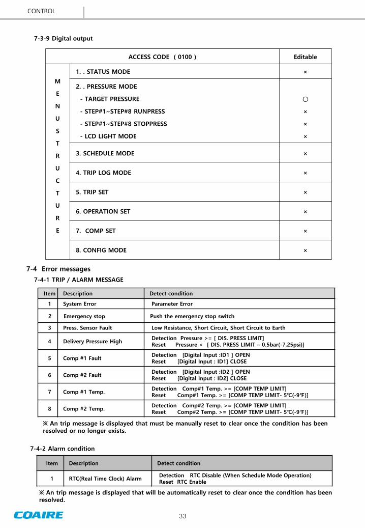

36
MAINTENANCE
NOTE Maintenance schedule is instructed as above The intervals are a guide based on normal operating conditions If operated in a severe environment necessary maintenance service should be performed on a more frequent basis User should carry out the maintenance work based on either the running hours or the calendar time whichever comes first
Check repair Replace
8-2 Scheduled Maintenance ndashHIGH PRESSURE 099 MPa(140psi) (Model CSOF- P H )
Maintenance should be followed below table
Section Action Taken
Times Interval Remarks
Every day
500hr 2500hr 5000hr 10000hr 20000hr
2 month 1 year 2 years 4 years 8 years
Water Drain Drain out
Suction Filter Clean Replace
exchange
in case of contamination
Airend fan Clean
Airend grease Re-grease
Use gunuine parts
Tip seal Replace
Dust seal Replace
Belt Check Replace
(first)
Loose tension causes noise
Temp sensor Check operation Replace in case
of abnormal operation
Pressure Sensor Check operation
Safety VV Check operation
Check VV Check Replace
Use gunuine
parts
Ventilation fan Check
Replace in case of abnormal operation
Magnetic contactor
Check Replace
Motor Check insulation
bearing
Suction hose Replace
After cooler Clean
exchange
in case of contamination
Control panel Check monitor
Piping Check leak
Airend Overhaul
Control box Clean
Check bolt
37
[ Fig8-1 ] Scroll Airend
[ Fig8-2 ] Vertical CSOF-M3PL(H)(P) CSOF-M5PL(H)(P)
[ Fig8-3 ] Horizontal CSOF-S8PL(H) CSOF-S10PL(H)
8-3 Maintenance
8-3-1 Regular Maintenance of the Airend
1) Check if there is any abnormal vibration or noise during a routine
operation and contact the nearest distributor if necessary
2) There are two types of the scroll airend Low Pressure (08 Mpa
115psi) and High Pressure (099MPa 140psi) The maintenance
period is different by type specified in the identification plate
attached on an airend The standard specification of COAIRE airend
is a low pressure type
3) Periodically lubricate an airend with grease See the maintenance
schedule for when the lubrication is needed
The airend consists of precision parts and needs special tool and jig for a repair and maintenance
It shall only be disassembled by our qualified engineer Contact the nearest distributor if necessary
Caution
8-3-2 Rotation of the Driving Part
If the motor is not started up or generates an abnormal noise stop the compressor turn the main
power off and then manually rotate the motor pulley If it does not rotate smoothly contact the
nearest distributor for a service It is mostly due to the damage on the motor bearing or when the
airend is stuck
Warning
An air compressor is automatically operated Do not come near the parts until the compressor is
stopped and the main power is turned off It may cause a serious personal injury if hair or clothes is
caught in the rotating parts
MAINTENANCE
38
[ Fig8-5 ] Belt align - CSOF-S8PL(H) CSOF-S10PL(H)
Adjust the belt tension in first 500 hrs after the purchase and every 3000 hrs (6 months) thereafter
in the following procedures
8-3-3 Adjustment of the Belt Tension
1) Use a tensiometer to measure the displacement of each belt
2) Loose the anchor bolt on the motor base and use the tension adjusting bolt to adjust the tension
with reference to the [Table 8-1]
3) Align the motor and tighten the anchor bolt on the motor base
Off-centered pulleys generate the noise and vibration and accelerate the process of wearing the belt
and pulley to cause the damage to the belt Align the center of the pulley during the replacement of a
belt and the adjustment of the belt tension With the compressor fixed loose the anchor bolt on the
motor and place an iron rule between the pulleys as shown in the following fig Gradually tighten the
anchor bolt on the motor and check the center is aligned between the pulleys Completely tighten the
bolt recheck the alignment and then rotate the pulley to check if the belt moves smoothly
8-3-4 Alignment of the Belt
MAINTENANCE
[ Table 8-1 ] Belt tension
[ Fig8-4 ] Belt tension check
Looseness = δ [mminch]
P [ kglbs] Model
New Displace
P (kglbs)
Δ (mminch)
P (kglbs)
Δ (mminch)
3HP HORIZON
1533 65 026rdquo 1329 64 025rdquo
5HP HORIZON
1738 6 023rdquo 1635 58 022rdquo
3HP VERTICAL
1533 5 019rdquo 1329 5 019rdquo
5HP VERTICAL
1738 5 019rdquo 1635 5 019rdquo
FIXED SIDEADJUSTED SIDE
AIRENDMOTOR
Belo
w 1
00
4(
mm
inch)
39
[ Fig8-8 ] Suction filter cleaning
[ Fig8-6 ] Belt Align ndash CSOF-M3PL(H)(P) CSOF-M5PL(H)(P)
[ Fig8-7 ] Belt Tension Settle-CSOF-M3PL(H)(P) CSOF-M5PL(H)(P)
1) An air compressor is automatically operated Do not check and replace the belt until the
compressor is stopped and the main power is turned off
2) Only use the belt specified by COAIRE for a replacement Do not use old and new belts mixed and
replace the entire set of belts all at once
3) The shaft is damaged and the service life of the bearing is shorten at a high tension of the belt
while the belt is slippery at a low tension of the belt Always keep the optimal tension value with
reference to the [Table 8-1]
Caution
8-3-5 Cleaning the Suction Filter
1) Check the contamination level every 500 hrs
2) Replace the heavily contaminated filter even before the
replacement period
3) Blow the element with the compressed air outward and
then by the side
4) Keep dust and foreign substances out of the compressor
during the assembly
Caution
A suction filter significantly affects the service life of an airend Make sure to use only the genuine
COAIRE suction filter COAIRE cannot be responsible for any damage caused by an improper
replacement
MAINTENANCE
Below 1mm(004)
FIXED SIDE
ADJUSTED SIDE
AIREND
MOTOR
40
9-1 Overview
90 Troubleshooting
The following flow diagrams show the procedures to repair the typical failures If the alarm is on and
the compressor is stopped do not restart the operation until the cause is clearly addressed and
eliminated Always turn the main power off and remove the pressure from the compressor prior to a
repair and maintenance
9-2 Flow Diagram for Troubleshooting
9-2-1 No Display
Negative-phase operation
Poor connection to power supply
Convert the phase for two of three main power lines
Abnormal noise
Start-Up Request a service
No Display
Poor connection to power supply
Yes
No
- Check the breaker switch
- Check the wiring
Yes
Failure of
controller
- Check the fuse
- Check the transformer
- The controller is defective
Yes
Start-Up Request a service
9-2- 2 Negative-Phase Operation
No
No
After eliminating the
cause
After eliminating the
cause
TROUBLESHOOTING
41
Unable to start motor
Lead-in wiring is disconnected
- Check the resistance of incoming line
- Test wiring and cable capacity and replace the cable if necessary
Yes
No
9-2-3 Unable to Start Motor
Failure of magnetic switch
- Test wiring
- Check the contact and operation
and replace the switch if necessary
Yes
Failure of motor
Check the error message on the controller
- Take necessary action to correct the error
- Check the tripping error No
Yes
- Test wiring and resistance
- Manually turn to check the bearing
- Replace the motor if necessary
Yes
No
Failure of compressor
No
- Manually turn to check the rotation
- Request a service if it is defective
Failure of controller
- Check the output signal of the magnetic switch
- Turn the main power off and then on
Yes
Yes
No
Start-Up Request a service
No
1) An air compressor is automatically operated Take necessary safety precaution to ensure that the
compressor is not unintentionally operated during the maintenance
2) Make sure to turn the main power off prior to the rotation test
3) Make sure to turn the main power off prior to the wiring test except for the measurement of the
voltage
Danger
After eliminating the cause
TROUBLESHOOTING
42
Low discharge pressure
- Clean the suction filter and replace if necessary
No
9-2-4 No Compression
Airend is damaged
- Check the rotation
- Check if there is any abnormal noise
Yes
Failure of controller
- Check the pipe for leakage
- Install an additional compressor if the capacity is insufficient
No
Yes
- Check the function of a multi-unit control
- Check the magnet and the output of the controller
Yes
No
Start-Up Request a service
No
9-2-5 Discharge Pressure Rise
Discharge Pressure Rise Error message ldquoHigh pressurerdquo appears
Check the operation of the pressure sensor
No
Yes
Failure of controller Check the output of the controller
No
Failure of pressure sensor
Safety valve is activated
Pressure sensor or safety valve is defective
Yes
No
Start-Up Request a service
Excessive amount of air used
Yes
Suction filter is clogged
Yes
After eliminating the cause
After eliminating the cause
TROUBLESHOOTING
43
9-2-6 Discharge Temperature Rise
Discharge temperature rise Error message ldquoHigh temprdquo appears
Start-Up Request a service
Check the controller
- Check the inputout of the temperature sensor
- Replace the temperature sensor if necessary
Yes
High ambient temperature
- Keep the internal temperature 40degC (104) or below
- Check the ventilation facility and duct
Yes
No
No
1) An appropriate temperature of an airend is 70degC(158 ) or below at the operating temperature
40degC(104) or below
2) Always take necessary action if the temperature of the airend is sharply increased with no
change in ambient temperature
Notes
9-3 Other Troubleshooting
Trouble Cause Action
1 Tripped due to
the over current
in motor
1) Compressor is tripped
- Foreign substance in the compressor
- Damage to the wrap of the compressor
- Low voltage
2) Open-phaseUnbalanced power supply
3) Deteriorated coil in the motor
4) Failure of EOCR
1) Contact the distributor
- Improve the power supply
2) Improve the power supply
3) Check the motor
4) Readjust or replace
2 Noise and
Vibration
1) Fixing bolts are loose
2) Noise from the compressor
- Bearing is worn out or damaged
- Foreign substance in the compressor
3) Improper belt tension and the damage
to the parts
4) Inadequate installation of the compressor
5) Failure of cooling fan (dust or damaged)
1) Readjust
2) Contact the distributor
3) Realign or replace the belt
4) Reinstall the compressor
5) Clean or replace the fan
After eliminating the cause
TROUBLESHOOTING
44
10-1 CSOF-S3PL(H)P CSOF-S5PL(H)P
100 Outline drawings
OUTLINE DRAWINGS
MAIN POWER30 HOLE
AIR OUTLET
PS 15A(PT 12)
정 기 점 검
25 [
09
843]
DRAIN HOLE12 HOLE
토 출 공 기 구
100 [
39
37]
50 [19685]
80 [31496]
217 [85433] 208 [8189]
92 [
36
22]
130 [
51
181]
550 [216535]
150 [59055]200 [7874]
150 [59055]25 [09843]
60 [
23
602]
720 [
283
484]
780 [
307
087]
550 [216535]
670 [
263
781]
115 [
45
276]
30 [11811]
45
10-2 CSOF-M3PL(H) CSOF-M5PL(H)
OUTLINE DRAWINGS
WATER DRAIN (14)
AIR DISCHARGE (12)
640 [252]
700 [2756]
POWER IN
CONTROLLER
EXHAUST AIR OUTLET(COOLING FAN)
EXHAUST AIR OUTLET(SIROCCO FAN)
166 [654] 118 [465]
57 [224] 28 [11]
153 [60
2]
301 [118
5]
213 [83
9]
25 [09
8]
1505
[59
3]
260 [102
4]
100 [394]
740 [2913]
1070 [421
3]
EMERGENCY
STOP
46
10-3 CSOF-S8PL(H) CSOF-S10PL(H)
OUTLINE DRAWINGS
EXHAUST AIR OUTLET
AIR OUTLETPS 25A(PS1)
215 [846]200 [787] 320 [126] 200 [787]
1150 [4528]
75 [295]
225 [88
6]
AIR INTLET118 [46
5]
40 [15
7]
122 [48]376 [148]
166 [65
4]
169 [665]221 [87]560 [220
5]
640 [252]
MAIN POWER INLET
160 [63
]
1020 [401
6]
EMERGENCY
STOP
47
110 Electrical wiring drawings
11-1 CSOF-M35PL(H) CSOF-S35PL(H)P 230V460V575V
ELECTRICAL WIRING DRAWINGS
1
PR
IMAR
Y
IN
PU
T V
OLTAG
E
SEC
ON
DAR
Y
110V (
100VA)
NO
TES
51C
OVER C
URREN
T R
ELAY F
OR M
C
MC
MO
TO
R F
OR C
OM
PRESSO
RTR
TRAN
SFO
RM
ER
ESP
EM
ERG
EN
CY S
TO
P P
USH
SW
ITC
HM
VM
OTO
R F
OR V
EN
TIL
ATIO
N F
AN
CP
CIR
CU
IT P
RO
TEC
TO
RN
FN
OIS
E F
ILTER
TH
TH
ERM
ISTO
RPT
PRESSU
RE T
RAN
SM
ITTER
DESC
RIP
TIO
N
52C
MAG
NETIC
CO
NTAC
TO
R F
OR M
C
SK
SU
RG
E K
ILLER
WIR
ING
NU
MB
ER
PR
IMAR
Y
IN
PU
T V
OLTAG
ESEC
ON
DAR
Y
110V
52C
51C
48
11-2 CSOF-S8PL(H) CSOF-S10PL(H) 230V460V575V
ELECTRICAL WIRING DRAWINGS
PRIM
ARY
IN
PU
T V
OLTAG
E
51C
OVER
CU
RR
EN
T R
ELAY F
OR
MC
MC
MO
TO
R F
OR
CO
MPR
ESSO
RTR
TR
AN
SFO
RM
ER
ESP
EM
ER
GEN
CY S
TO
P P
USH
SW
ITC
HM
VM
OTO
R F
OR
VEN
TIL
ATIO
N F
AN
CP
CIR
CU
IT P
RO
TEC
TO
RN
FN
OIS
E F
ILTER
TH
TH
ER
MIS
TO
RPT
PR
ESSU
RE T
RAN
SM
ITTER
DESC
RIP
TIO
N
52C
MAG
NETIC
CO
NTAC
TO
R F
OR
MC
SK
SU
RG
E K
ILLER
WIR
ING
NU
MB
ER
SEC
ON
DARY
110V
49
11-3 CSOF-M35PL(H) CSOF-S35PL(H)P 1PH 230V
1
PRIM
ARY
IN
PU
T V
OLTAG
E
SEC
ON
DARY
110V (
100VA)
NO
TES
51C
OVER C
URREN
T R
ELAY F
OR M
C
MC
MO
TO
R F
OR C
OM
PRESSO
RTR
TRAN
SFO
RM
ER
ESP
EM
ERG
EN
CY S
TO
P P
USH
SW
ITC
HM
VM
OTO
R F
OR V
EN
TIL
ATIO
N F
AN
CP
CIR
CU
IT P
RO
TEC
TO
RN
FN
OIS
E F
ILTER
TH
TH
ERM
ISTO
RPT
PRESSU
RE T
RAN
SM
ITTER
DESC
RIP
TIO
N
52C
MAG
NETIC
CO
NTAC
TO
R F
OR M
C
SK
SU
RG
E K
ILLER
WIR
ING
NU
MB
ER
PR
IMARY
IN
PU
T V
OLTAG
ESEC
ON
DAR
Y
110V
52C
51C
ELECTRICAL WIRING DRAWINGS
50
11-4 CSOF-S8PL(H) CSOF-S10PL(H) 1PH 230V
ELECTRICAL WIRING DRAWINGS
PRIM
ARY
IN
PU
T V
OLTAG
E
51C
OVER
CU
RR
EN
T R
ELAY F
OR
MC
MC
MO
TO
R F
OR
CO
MPR
ESSO
RTR
TR
AN
SFO
RM
ER
ESP
EM
ER
GEN
CY S
TO
P P
USH
SW
ITC
HM
VM
OTO
R F
OR
VEN
TIL
ATIO
N F
AN
CP
CIR
CU
IT P
RO
TEC
TO
RN
FN
OIS
E F
ILTER
TH
TH
ER
MIS
TO
RPT
PR
ESSU
RE T
RAN
SM
ITTER
DESC
RIP
TIO
N
52C
MAG
NETIC
CO
NTAC
TO
R F
OR M
C
SK
SU
RG
E K
ILLER
WIR
ING
NU
MB
ER
SEC
ON
DARY
110V
STARTUP REPORT Please fill out completely and return to the factory to validate warranty
CUSTOMER AND MACHINE INFORMATION
CUSTOMER FACTORY SHIP DATE
ADDRESS DATE STARTED UP
CITYSTATE MODEL NUMBER PHONE SERIAL NUMBER WRITTTEN BY HOURS ON MACHINE Hrs
MACHINE INFORMATIONS AND INITIAL STARTUP
Compressor Environment- excellent good fair poor
Machine Location ndash indoors outdoors
if outdoors protected from rain Yes No
Approx ambient temperature______ adequate ventilation - Yes No
Did you check for correct rotation Yes No
Nameplate amperage for voltage used ______
Incoming Voltages
L1-L2 L2-L3 L1-L3
Volts Volts Volts
Full load amperage at _________ PSIG
L1 L2 L3
Amp Amp Amp
Unload amperage at _________ PSIG
L1 L2 L3
Amp Amp Amp
Is the machine on a level and stable surface Yes No
Was a flexible connector used to connect piping ndash Yes No
Approx time spent during startup procedure ___________ Hrs
Did you advice customer on operation and maintenance of machine Yes No
Application and installation comments
___________________________________________________________________________________________________
Machine Sold By(Company) __________________ Sales Person ___________________________ Startup performed by _______________ Date _________________________________
THERE IS NO WARRANTY WITHOUT THIS REPORT
Warranty Claim Report Please complete the following claim form your claim will be confirmed by our sales representative
To Coaire Division of Quietside 8750 Pioneer Blvd Santa Fe Springs CA 90670 Tel(562)576-1330Fax(562)699-4351 email supportcoairecom
Distributor
Company Date
Address Model
Serial No
Customer
Company Run Hours Hrs
Address Setting Press PSIG
OPERATING CONDITIONS Percent() on load Ambient Temperature F No of days of operation weekly Days Discharge temperature F Hours per day Hours Compressor area temperature F Machine setting OLOL or Mod Environment 1)
1) 1 to 10 1 being clean 10 very dirty
Incoming Voltages Full load amperage at _______ PSIG Unload amperage at ______ PSIG
L1 - L2 L2 - L3 L1 - L3 L1 - L2 L2 - L3 L1 - L3 L1 - L2 L2 - L3 L1 - L3
Volts Volts Volts Amp Amp Amp Amp Amp Amp
Symptom
Fault Diagnosis
Resolution
Parts required Labor Cost No Item Number DescriptionMFGR Part Number Quantity Labor Time Hrs x $Hrs= $
01 Travel Time Hrs x $Hrs= $
02 Total Amount
03 04 Technicianrsquos name
WRITTEN BY
SIGNATURE
X
COAIRE reserves the right to make changes at any time without notice as a result of our commitment to continuous improvement
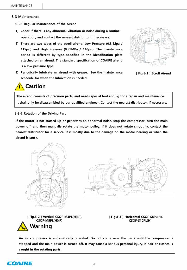

39
[ Fig8-8 ] Suction filter cleaning
[ Fig8-6 ] Belt Align ndash CSOF-M3PL(H)(P) CSOF-M5PL(H)(P)
[ Fig8-7 ] Belt Tension Settle-CSOF-M3PL(H)(P) CSOF-M5PL(H)(P)
1) An air compressor is automatically operated Do not check and replace the belt until the
compressor is stopped and the main power is turned off
2) Only use the belt specified by COAIRE for a replacement Do not use old and new belts mixed and
replace the entire set of belts all at once
3) The shaft is damaged and the service life of the bearing is shorten at a high tension of the belt
while the belt is slippery at a low tension of the belt Always keep the optimal tension value with
reference to the [Table 8-1]
Caution
8-3-5 Cleaning the Suction Filter
1) Check the contamination level every 500 hrs
2) Replace the heavily contaminated filter even before the
replacement period
3) Blow the element with the compressed air outward and
then by the side
4) Keep dust and foreign substances out of the compressor
during the assembly
Caution
A suction filter significantly affects the service life of an airend Make sure to use only the genuine
COAIRE suction filter COAIRE cannot be responsible for any damage caused by an improper
replacement
MAINTENANCE
Below 1mm(004)
FIXED SIDE
ADJUSTED SIDE
AIREND
MOTOR
40
9-1 Overview
90 Troubleshooting
The following flow diagrams show the procedures to repair the typical failures If the alarm is on and
the compressor is stopped do not restart the operation until the cause is clearly addressed and
eliminated Always turn the main power off and remove the pressure from the compressor prior to a
repair and maintenance
9-2 Flow Diagram for Troubleshooting
9-2-1 No Display
Negative-phase operation
Poor connection to power supply
Convert the phase for two of three main power lines
Abnormal noise
Start-Up Request a service
No Display
Poor connection to power supply
Yes
No
- Check the breaker switch
- Check the wiring
Yes
Failure of
controller
- Check the fuse
- Check the transformer
- The controller is defective
Yes
Start-Up Request a service
9-2- 2 Negative-Phase Operation
No
No
After eliminating the
cause
After eliminating the
cause
TROUBLESHOOTING
41
Unable to start motor
Lead-in wiring is disconnected
- Check the resistance of incoming line
- Test wiring and cable capacity and replace the cable if necessary
Yes
No
9-2-3 Unable to Start Motor
Failure of magnetic switch
- Test wiring
- Check the contact and operation
and replace the switch if necessary
Yes
Failure of motor
Check the error message on the controller
- Take necessary action to correct the error
- Check the tripping error No
Yes
- Test wiring and resistance
- Manually turn to check the bearing
- Replace the motor if necessary
Yes
No
Failure of compressor
No
- Manually turn to check the rotation
- Request a service if it is defective
Failure of controller
- Check the output signal of the magnetic switch
- Turn the main power off and then on
Yes
Yes
No
Start-Up Request a service
No
1) An air compressor is automatically operated Take necessary safety precaution to ensure that the
compressor is not unintentionally operated during the maintenance
2) Make sure to turn the main power off prior to the rotation test
3) Make sure to turn the main power off prior to the wiring test except for the measurement of the
voltage
Danger
After eliminating the cause
TROUBLESHOOTING
42
Low discharge pressure
- Clean the suction filter and replace if necessary
No
9-2-4 No Compression
Airend is damaged
- Check the rotation
- Check if there is any abnormal noise
Yes
Failure of controller
- Check the pipe for leakage
- Install an additional compressor if the capacity is insufficient
No
Yes
- Check the function of a multi-unit control
- Check the magnet and the output of the controller
Yes
No
Start-Up Request a service
No
9-2-5 Discharge Pressure Rise
Discharge Pressure Rise Error message ldquoHigh pressurerdquo appears
Check the operation of the pressure sensor
No
Yes
Failure of controller Check the output of the controller
No
Failure of pressure sensor
Safety valve is activated
Pressure sensor or safety valve is defective
Yes
No
Start-Up Request a service
Excessive amount of air used
Yes
Suction filter is clogged
Yes
After eliminating the cause
After eliminating the cause
TROUBLESHOOTING
43
9-2-6 Discharge Temperature Rise
Discharge temperature rise Error message ldquoHigh temprdquo appears
Start-Up Request a service
Check the controller
- Check the inputout of the temperature sensor
- Replace the temperature sensor if necessary
Yes
High ambient temperature
- Keep the internal temperature 40degC (104) or below
- Check the ventilation facility and duct
Yes
No
No
1) An appropriate temperature of an airend is 70degC(158 ) or below at the operating temperature
40degC(104) or below
2) Always take necessary action if the temperature of the airend is sharply increased with no
change in ambient temperature
Notes
9-3 Other Troubleshooting
Trouble Cause Action
1 Tripped due to
the over current
in motor
1) Compressor is tripped
- Foreign substance in the compressor
- Damage to the wrap of the compressor
- Low voltage
2) Open-phaseUnbalanced power supply
3) Deteriorated coil in the motor
4) Failure of EOCR
1) Contact the distributor
- Improve the power supply
2) Improve the power supply
3) Check the motor
4) Readjust or replace
2 Noise and
Vibration
1) Fixing bolts are loose
2) Noise from the compressor
- Bearing is worn out or damaged
- Foreign substance in the compressor
3) Improper belt tension and the damage
to the parts
4) Inadequate installation of the compressor
5) Failure of cooling fan (dust or damaged)
1) Readjust
2) Contact the distributor
3) Realign or replace the belt
4) Reinstall the compressor
5) Clean or replace the fan
After eliminating the cause
TROUBLESHOOTING
44
10-1 CSOF-S3PL(H)P CSOF-S5PL(H)P
100 Outline drawings
OUTLINE DRAWINGS
MAIN POWER30 HOLE
AIR OUTLET
PS 15A(PT 12)
정 기 점 검
25 [
09
843]
DRAIN HOLE12 HOLE
토 출 공 기 구
100 [
39
37]
50 [19685]
80 [31496]
217 [85433] 208 [8189]
92 [
36
22]
130 [
51
181]
550 [216535]
150 [59055]200 [7874]
150 [59055]25 [09843]
60 [
23
602]
720 [
283
484]
780 [
307
087]
550 [216535]
670 [
263
781]
115 [
45
276]
30 [11811]
45
10-2 CSOF-M3PL(H) CSOF-M5PL(H)
OUTLINE DRAWINGS
WATER DRAIN (14)
AIR DISCHARGE (12)
640 [252]
700 [2756]
POWER IN
CONTROLLER
EXHAUST AIR OUTLET(COOLING FAN)
EXHAUST AIR OUTLET(SIROCCO FAN)
166 [654] 118 [465]
57 [224] 28 [11]
153 [60
2]
301 [118
5]
213 [83
9]
25 [09
8]
1505
[59
3]
260 [102
4]
100 [394]
740 [2913]
1070 [421
3]
EMERGENCY
STOP
46
10-3 CSOF-S8PL(H) CSOF-S10PL(H)
OUTLINE DRAWINGS
EXHAUST AIR OUTLET
AIR OUTLETPS 25A(PS1)
215 [846]200 [787] 320 [126] 200 [787]
1150 [4528]
75 [295]
225 [88
6]
AIR INTLET118 [46
5]
40 [15
7]
122 [48]376 [148]
166 [65
4]
169 [665]221 [87]560 [220
5]
640 [252]
MAIN POWER INLET
160 [63
]
1020 [401
6]
EMERGENCY
STOP
47
110 Electrical wiring drawings
11-1 CSOF-M35PL(H) CSOF-S35PL(H)P 230V460V575V
ELECTRICAL WIRING DRAWINGS
1
PR
IMAR
Y
IN
PU
T V
OLTAG
E
SEC
ON
DAR
Y
110V (
100VA)
NO
TES
51C
OVER C
URREN
T R
ELAY F
OR M
C
MC
MO
TO
R F
OR C
OM
PRESSO
RTR
TRAN
SFO
RM
ER
ESP
EM
ERG
EN
CY S
TO
P P
USH
SW
ITC
HM
VM
OTO
R F
OR V
EN
TIL
ATIO
N F
AN
CP
CIR
CU
IT P
RO
TEC
TO
RN
FN
OIS
E F
ILTER
TH
TH
ERM
ISTO
RPT
PRESSU
RE T
RAN
SM
ITTER
DESC
RIP
TIO
N
52C
MAG
NETIC
CO
NTAC
TO
R F
OR M
C
SK
SU
RG
E K
ILLER
WIR
ING
NU
MB
ER
PR
IMAR
Y
IN
PU
T V
OLTAG
ESEC
ON
DAR
Y
110V
52C
51C
48
11-2 CSOF-S8PL(H) CSOF-S10PL(H) 230V460V575V
ELECTRICAL WIRING DRAWINGS
PRIM
ARY
IN
PU
T V
OLTAG
E
51C
OVER
CU
RR
EN
T R
ELAY F
OR
MC
MC
MO
TO
R F
OR
CO
MPR
ESSO
RTR
TR
AN
SFO
RM
ER
ESP
EM
ER
GEN
CY S
TO
P P
USH
SW
ITC
HM
VM
OTO
R F
OR
VEN
TIL
ATIO
N F
AN
CP
CIR
CU
IT P
RO
TEC
TO
RN
FN
OIS
E F
ILTER
TH
TH
ER
MIS
TO
RPT
PR
ESSU
RE T
RAN
SM
ITTER
DESC
RIP
TIO
N
52C
MAG
NETIC
CO
NTAC
TO
R F
OR
MC
SK
SU
RG
E K
ILLER
WIR
ING
NU
MB
ER
SEC
ON
DARY
110V
49
11-3 CSOF-M35PL(H) CSOF-S35PL(H)P 1PH 230V
1
PRIM
ARY
IN
PU
T V
OLTAG
E
SEC
ON
DARY
110V (
100VA)
NO
TES
51C
OVER C
URREN
T R
ELAY F
OR M
C
MC
MO
TO
R F
OR C
OM
PRESSO
RTR
TRAN
SFO
RM
ER
ESP
EM
ERG
EN
CY S
TO
P P
USH
SW
ITC
HM
VM
OTO
R F
OR V
EN
TIL
ATIO
N F
AN
CP
CIR
CU
IT P
RO
TEC
TO
RN
FN
OIS
E F
ILTER
TH
TH
ERM
ISTO
RPT
PRESSU
RE T
RAN
SM
ITTER
DESC
RIP
TIO
N
52C
MAG
NETIC
CO
NTAC
TO
R F
OR M
C
SK
SU
RG
E K
ILLER
WIR
ING
NU
MB
ER
PR
IMARY
IN
PU
T V
OLTAG
ESEC
ON
DAR
Y
110V
52C
51C
ELECTRICAL WIRING DRAWINGS
50
11-4 CSOF-S8PL(H) CSOF-S10PL(H) 1PH 230V
ELECTRICAL WIRING DRAWINGS
PRIM
ARY
IN
PU
T V
OLTAG
E
51C
OVER
CU
RR
EN
T R
ELAY F
OR
MC
MC
MO
TO
R F
OR
CO
MPR
ESSO
RTR
TR
AN
SFO
RM
ER
ESP
EM
ER
GEN
CY S
TO
P P
USH
SW
ITC
HM
VM
OTO
R F
OR
VEN
TIL
ATIO
N F
AN
CP
CIR
CU
IT P
RO
TEC
TO
RN
FN
OIS
E F
ILTER
TH
TH
ER
MIS
TO
RPT
PR
ESSU
RE T
RAN
SM
ITTER
DESC
RIP
TIO
N
52C
MAG
NETIC
CO
NTAC
TO
R F
OR M
C
SK
SU
RG
E K
ILLER
WIR
ING
NU
MB
ER
SEC
ON
DARY
110V
STARTUP REPORT Please fill out completely and return to the factory to validate warranty
CUSTOMER AND MACHINE INFORMATION
CUSTOMER FACTORY SHIP DATE
ADDRESS DATE STARTED UP
CITYSTATE MODEL NUMBER PHONE SERIAL NUMBER WRITTTEN BY HOURS ON MACHINE Hrs
MACHINE INFORMATIONS AND INITIAL STARTUP
Compressor Environment- excellent good fair poor
Machine Location ndash indoors outdoors
if outdoors protected from rain Yes No
Approx ambient temperature______ adequate ventilation - Yes No
Did you check for correct rotation Yes No
Nameplate amperage for voltage used ______
Incoming Voltages
L1-L2 L2-L3 L1-L3
Volts Volts Volts
Full load amperage at _________ PSIG
L1 L2 L3
Amp Amp Amp
Unload amperage at _________ PSIG
L1 L2 L3
Amp Amp Amp
Is the machine on a level and stable surface Yes No
Was a flexible connector used to connect piping ndash Yes No
Approx time spent during startup procedure ___________ Hrs
Did you advice customer on operation and maintenance of machine Yes No
Application and installation comments
___________________________________________________________________________________________________
Machine Sold By(Company) __________________ Sales Person ___________________________ Startup performed by _______________ Date _________________________________
THERE IS NO WARRANTY WITHOUT THIS REPORT
Warranty Claim Report Please complete the following claim form your claim will be confirmed by our sales representative
To Coaire Division of Quietside 8750 Pioneer Blvd Santa Fe Springs CA 90670 Tel(562)576-1330Fax(562)699-4351 email supportcoairecom
Distributor
Company Date
Address Model
Serial No
Customer
Company Run Hours Hrs
Address Setting Press PSIG
OPERATING CONDITIONS Percent() on load Ambient Temperature F No of days of operation weekly Days Discharge temperature F Hours per day Hours Compressor area temperature F Machine setting OLOL or Mod Environment 1)
1) 1 to 10 1 being clean 10 very dirty
Incoming Voltages Full load amperage at _______ PSIG Unload amperage at ______ PSIG
L1 - L2 L2 - L3 L1 - L3 L1 - L2 L2 - L3 L1 - L3 L1 - L2 L2 - L3 L1 - L3
Volts Volts Volts Amp Amp Amp Amp Amp Amp
Symptom
Fault Diagnosis
Resolution
Parts required Labor Cost No Item Number DescriptionMFGR Part Number Quantity Labor Time Hrs x $Hrs= $
01 Travel Time Hrs x $Hrs= $
02 Total Amount
03 04 Technicianrsquos name
WRITTEN BY
SIGNATURE
X
COAIRE reserves the right to make changes at any time without notice as a result of our commitment to continuous improvement
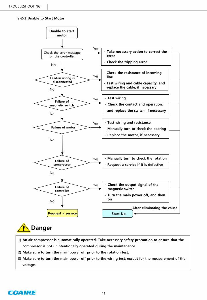

COAIRE reserves the right to make changes at any time without notice as a result of our commitment to continuous improvement