Instruction Manual - ing- Instruction Manual Ing. Büro Wörner - Soft- und...
22
Ing. Büro Wörner Dipl. Ing. Peter Wörner Soft- und Hardware-Entwicklung Messdatenerfassung Dreissig Morgen Weg 13 D-69198 Schriesheim Tel. +49-(0)6203 / 96 16 79 Fax +49-(0)6203 / 96 16 80 email: info@ linemeasurement.com www.linemeasurement.com Instruction Manual Programmable Length Measuring System PLMG
Transcript of Instruction Manual - ing- Instruction Manual Ing. Büro Wörner - Soft- und...

Ing. Büro Wörner Dipl. Ing. Peter Wörner Soft- und Hardware-Entwicklung Messdatenerfassung
Dreissig Morgen Weg 13 D-69198 Schriesheim Tel. +49-(0)6203 / 96 16 79 Fax +49-(0)6203 / 96 16 80 email: info@ linemeasurement.com www.linemeasurement.com
Instruction Manual
Programmable Length Measuring System PLMG

Introduction - 2 -
Contents 0. Introduction.........................................................................................................3
1. Installation ..........................................................................................................4
1.1 Product Description .........................................................................................4
1.2 Assembly .........................................................................................................6
2. Setup of Measuring System................................................................................9
2.1 Software Installation ........................................................................................9
2.2 Functional Test ................................................................................................9
3. Measurement....................................................................................................10
3.1 Using the Readout Software..........................................................................10
3.2 Adjustable Parameters ..................................................................................11
3.3 Taring of Measurement Range ......................................................................12
3.4 Starting the Measurement .............................................................................12
3.5 Tractive Force Check (Option EZM) ..............................................................12
4. Worksheet Templates.......................................................................................14
5. Troubleshooting................................................................................................14
6. Maintenance .....................................................................................................15
7. Warranty and Liability .......................................................................................15
Appendix A - Technical Specification.........................................................................16
Appendix B - Connector Pinouts................................................................................17
Appendix C - Error Messages....................................................................................18
Appendix D - Quick Instructions ZM-2 .......................................................................19
Appendix E - Excel Worksheet Template ..................................................................21
Appendix F - Measurement Assembly.......................................................................22
Windows and Excel are trademarks of Microsoft Corporation.
Ing. Büro Wörner - Soft- und Hardware-Entwicklung - Messdatenerfassung
Dreissig Morgen Weg 13 D-69198 Schriesheim Tel. +49 - (0)6203 / 96 16 79 Fax 96 16 80
Instruction Manual PLMG Type 01 English Version 1.92 May 2005 Copyright 1996-2005 Ing. Büro Wörner

Installation - 3 -
0. Introduction
Features
• High accuracy
• Measurements completed in short time
• Documentation by computerized data sheets
• Avoiding of error prone and time consuming data entry by hand
• Compatible with most Windows™ applications
• Easy installation and operation
• Operation by a single person
Advantages Data entry by hand and the error possibilities entailed as well as a second person as assistant can be avoided. Dramatically shortened measurement times combined with high accuracy and repeatability are achieved. Connection to a tractive force measuring device reduces the possibility of operator influence. Computerized protocol sheets offer professional documentation and readability of data. Principle of Measurement A stainless steel cable connected to a highly accurate position transducer is pulled out parallel to the paraglider line. The length is read out from the transducer and displayed by a digital instrument with an accuracy down to a millimetre. A computer program reads out the displayed data through a serial link and transfers the figures directly into any Windows™ application, e.g. an Excel™ chart. The read out command can be given either via foot switch or automatically through an interconnected force measuring device on attaining a tractive force within a given range (e.g. 5 dN). The measuring range of 2 500 mm can be shifted to any range between 0 and 12 000 mm by exten-ding the transducer cable with any appropriate non-elastic(!) line and using the taring function of the software. A range of 4 500 - 7 000 mm might be chosen as suitable for most line lengths. This range can easily be readjusted via software at any time by the operator.
Ing. Büro Wörner - Soft- und Hardware-Entwicklung - Messdatenerfassung
Dreissig Morgen Weg 13 D-69198 Schriesheim Tel. 06203 / 96 16 79 Fax 96 16 80

Installation - 4 -
1. Installation
Precautions Warning: Don't let sensor cable snap back!! Don't let travel overrange! Operate sensor only with guarding line! Make sure sensor is electrically grounded! Uncontrolled snapping of cable will lead to severe damage of sensor!! Operate sensor only with a guarding line or counterweight.
1.1 Product Description • Display Instrument PLMG • Position Transducer (Sensor) • Baseplate (sensor mounting) incl. 4 screws for sensor
• Connection Cable Sensor - PLMG
• Connection Cable PLMG - Computer
• Readout Software (CD-ROM or 3,5" diskette)
• Instruction Manual
Ing. Büro Wörner - Soft- und Hardware-Entwicklung - Messdatenerfassung
Dreissig Morgen Weg 13 D-69198 Schriesheim Tel. +49 - (0)6203 / 96 16 79 Fax 96 16 80

Installation - 5 -
• Optional: Foot Switch Additionally for Tractive Force Checking (Option EZM) • Tractive Force Measurement Device ZM-2
• Tractive Force Quick Check Display Unit ZAE
• Connection Cable Sensor – ZM-2 - PLMG
Ing. Büro Wörner - Soft- und Hardware-Entwicklung - Messdatenerfassung
Dreissig Morgen Weg 13 D-69198 Schriesheim Tel. 06203 / 96 16 79 Fax 96 16 80

Installation - 6 -
1.2 Assembly • Screw sensor to baseplate.
Screws are enclosed with baseplate. "Long" side of baseplate (greater distance between holes) should point to cable outlet side of sensor.
• Mount sensor with baseplate at suitable place (wallboard, table). Cable should not be pulled out at an angle > 15° during measurements. This might lead to fast wear of cable.
• Attach a guarding line or counterweight to sensor cable. Such a precautionary measure is mandatory for protection of sensor! Suitable is any elastic line (e.g. Reepschnur 3 - 5 mm) fixed at the opposite wall. Length should be calculated to stop sensor cable just before travelling against cable outlet to avoid damage by sudden breaking. Alternatively the line could be fixed to the ceiling (instead of opposite wall).
An even better solution could be a freely travelling line with a counterweight (600 - 800 gr) running over 2 guide wheels fixed to the opposite wall.
A second line might serve as protection against pulling out the sensor cable over the end limit. Fix between sensor and cable, length should be a little less than sensor cable.
Ing. Büro Wörner - Soft- und Hardware-Entwicklung - Messdatenerfassung
Dreissig Morgen Weg 13 D-69198 Schriesheim Tel. 06203 / 96 16 79 Fax 96 16 80
diff. possible attachments of guarding line Sensor
Sensor cable with extension
Range Limit Protection Line

Installation - 7 -
• Prepare a fixing for paraglider lines or risers somewhere near the sensor cable outlet (not required when working with force measurement - Option EZM).
• Place display instrument PLMG and computer in a suitable position.
The operator should be capable of both reading out the display as well as handling the computer.
• Connect all cables including power supply.
Connectors should be screwed to avoid accidental loosening.. Connection to computer is done through a free serial port (usually COM1 or COM2). Generally one of the ports is used for the mouse. In case of problems contact your dealer.
• Optional: Connect foot switch.
A second switch may be installed for "backskipping". This allows the operator to step back quickly in the application program after accidentally skipping an input cell. Connection see Appendix B.
• Prepare suitable extension(s) for measuring the usual line lengths.
Such extensions are required to shift the sensor range (2,5 m) into the usual range of paraglider lines (approx. 4,5 - 8 m). Any non-elastic line should be suitable (thin steel cable is excellent) - the exact length is uncritical due to the taring function of the readout software. Stretching during measurement though will influence the accuracy of the system. Prefabricated lines of any length can be ordered through Ing. Büro Wörner.
Ing. Büro Wörner - Soft- und Hardware-Entwicklung - Messdatenerfassung
Dreissig Morgen Weg 13 D-69198 Schriesheim Tel. 06203 / 96 16 79 Fax 96 16 80
Measurement Range (e.g. 4,0 - 6,5 m)
Reference Point Extension
Sensor
A hand loop (e.g. rope loop, brake loop) should be used for better handling and to avoid accidental slipping of cable/extension. In addition such a loop makes for a good reference point for the measurement.
Should it be necessary to guide the sensor cable around angles >15° (when mounting sensor under table), a suitable cable guide wheel allowing guiding up to 180° can be obtained as accessory.
Installation - 8 -
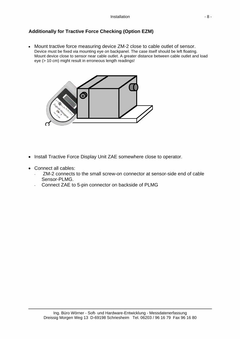
Additionally for Tractive Force Checking (Option EZM) • Mount tractive force measuring device ZM-2 close to cable outlet of sensor.
Device must be fixed via mounting eye on backpanel. The case itself should be left floating. Mount device close to sensor near cable outlet. A greater distance between cable outlet and load eye (> 10 cm) might result in erroneous length readings!
• Install Tractive Force Display Unit ZAE somewhere close to operator. • Connect all cables:
- ZM-2 connects to the small screw-on connector at sensor-side end of cable Sensor-PLMG.
- Connect ZAE to 5-pin connector on backside of PLMG
Ing. Büro Wörner - Soft- und Hardware-Entwicklung - Messdatenerfassung
Dreissig Morgen Weg 13 D-69198 Schriesheim Tel. 06203 / 96 16 79 Fax 96 16 80

Setup - 9 -
2. Setup of Measuring System
2.1 Software Installation The readout software requires Windows 95 or newer. To start the installation program insert CD in drive and run ‘<cd drive>:\Setup.exe’. The setup program copies all files necessary files to the user's harddisk and installs the readout application software "WSRead32". Virtually any Windows application can be used to receive the read out data. We recommend to use Excel (Version 95 or higher) or any similar spreadsheet application as these programs allow processing of data by user. Database applications might be another suitable choice. Note: A version of the software for systems using Windows 3.1 is available on request.
2.2 Functional Test • Switch on Display Instrument PLMG.
After power-on initialisation a (random) length value should be displayed. • Pull out sensor cable carefully for a few centimetres (use guarding line!).
Display should change now in steps of one millimetre corresponding to the length pulled out. Accuracy could be checked with a tape measure.
• Run the readout application "WSRead32". • Start readout by clicking "Start!".
Menu text should change to "Stop!", menu bar should be flashing indicating active reading. • Check taring function.
Command: Settings - Taring - OK. Display should show taring reference value now. The taring reference value can be change in the "Options" dialog and is displayed in the taring dialog box text..
On malfunction check cable connections and serial port selection first. For more detailed information on functional problems see chapter "Troubleshooting".
Ing. Büro Wörner - Soft- und Hardware-Entwicklung - Messdatenerfassung
Dreissig Morgen Weg 13 D-69198 Schriesheim Tel. +49 - (0)6203 / 96 16 79 Fax 96 16 80
Measurement - 10 -
3. Measurement
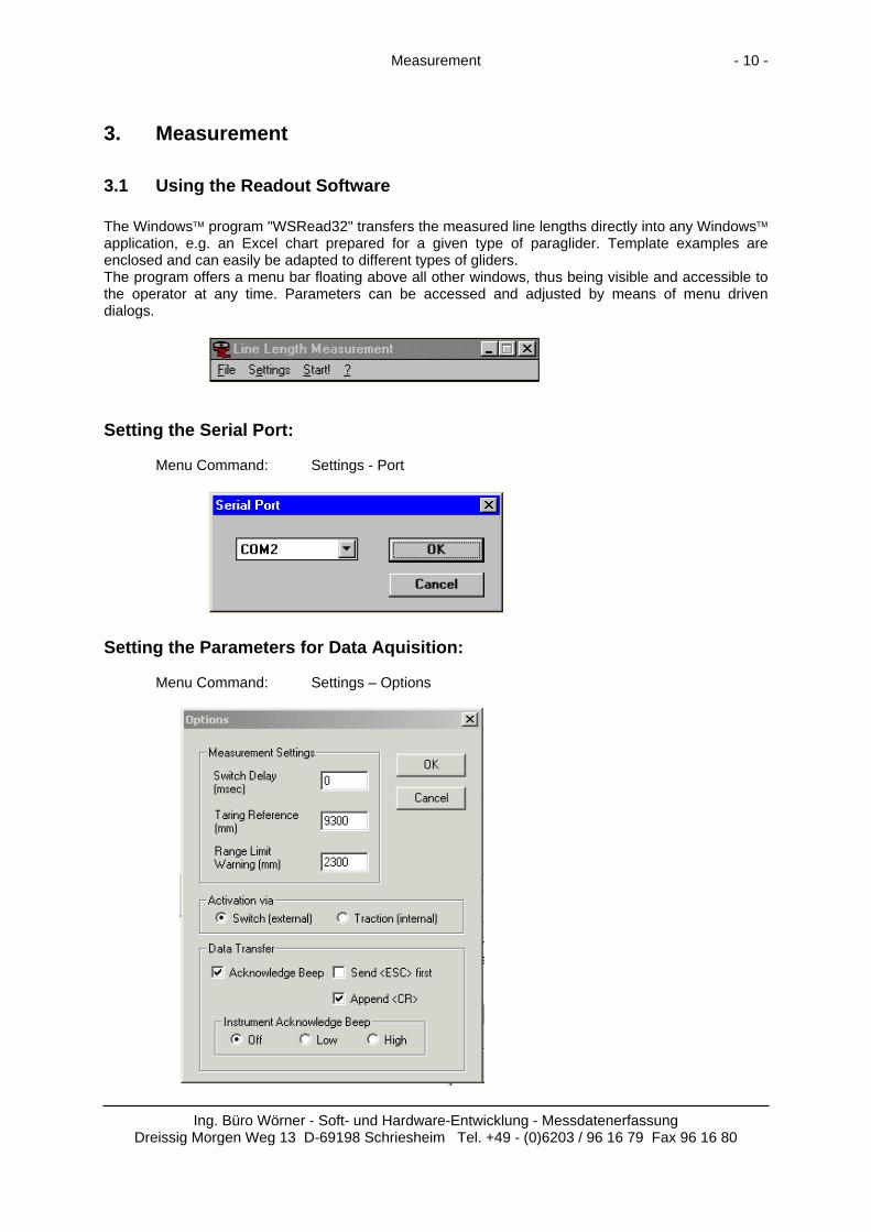
3.1 Using the Readout Software The Windows™ program "WSRead32" transfers the measured line lengths directly into any Windows™ application, e.g. an Excel chart prepared for a given type of paraglider. Template examples are enclosed and can easily be adapted to different types of gliders. The program offers a menu bar floating above all other windows, thus being visible and accessible to the operator at any time. Parameters can be accessed and adjusted by means of menu driven dialogs.
Setting the Serial Port: Menu Command: Settings - Port
Setting the Parameters for Data Aquisition: Menu Command: Settings – Options
Ing. Büro Wörner - Soft- und Hardware-Entwicklung - Messdatenerfassung Dreissig Morgen Weg 13 D-69198 Schriesheim Tel. +49 - (0)6203 / 96 16 79 Fax 96 16 80

Measurement - 11 -
3.2 Adjustable Parameters
Switch Delay Delay of data transfre to computer. Especially useful in conjunction with tractive force checking to avoid inaccurate readouts. A useful setting could be e.g. 1000 msec (1 sec), best results can be found by experiment. Valid range: 0 to 10 000 msec
Taring Reference Taring reference for length measurement.
Valid range: 0 to 9 500 mm Range Limit Warning Warning threshold for end-of-range. The PLMG will beep on exceeding this
limit to warn against possible damage to the cable and sensor by extending the cable beyond its end. Valid values: 0 to 5 000 mm. Usual setting: approx. 2 300 mm with measurement ranges of 2 500 mm. Caveats: This value is independent of the taring value and relates directly to the sensor range (gen. 0 - 2 500 mm)!
Activation via Trigger of data transfer via switch (external, manually) or on reaching a
predefined traction force (internal, automatically). When triggering via traction a delay should be used (see "Switch Delay"). Triggering via tractive force requires the option 'EZM' for tractive force checking to be built in.
Acknowledge Beep Acknowledgement of data transfer by sound (Computer and PLMG). Visual Acknowledge Acknowledgement of data transfer by flashing a symbol on the screen. Send <ESC> first An <Escape> is sent to the aplication program before data transfer. Append <CR> An <Enter> (“Carriage Return“) is sent to the application program after data
transfer. Instrument Acknowledge Beep
Acknowledge of data transfer via internal sounder of display instrument. Settings: Off - Low - High.
Ing. Büro Wörner - Soft- und Hardware-Entwicklung - Messdatenerfassung
Dreissig Morgen Weg 13 D-69198 Schriesheim Tel. 06203 / 96 16 79 Fax 96 16 80

Measurement - 12 -
3.3 Taring of Measurement Range Menu Command: Settings - Taring
The measurement range of 2 500 mm can be shifted to any range betwen 0 and 12 000 mm by the taring command. The taring reference value is set in the 'options' dialog. The setting of the taring reference can be done either by clicking 'OK' or via the enter key.
When measurement is activated (Menu 'Start!'), taring can be triggered via switch or traction. The operator is then not forced to be close to the computer and may execute the taring via foot switch or traction. This also allows for using a paraglider line (e.g. a middle B line) as reference under true measurement conditions (tractive force!). All measurements made thereafter will be relative to the choosen reference line and can be measured under identical conditions.
3.4 Starting the Measurement Measurement is started by clicking 'Start!'. The menu text will change to 'Stop!' to indicate activation. The taskbar will flash as long as the measurement is activated. The length data is sent to the application program on activation command (foot switch or tractive force) as string data - exactly as data entered by hand via keyboard. The application program (usually 'Excel') has to be active and the appropriate field must be clicked with the mouse (input focus). To stop the measurement, click ‘Stop!’.
3.5 Tractive Force Check (Option EZM) When using tractive force checking the appropriate parameters (force thresholds) must be set in the force measurement device ZM-2.
See Appendix D for details. Usually thresholds of 45 N and 55 N respectively might be used (i.e. 5 kp +- 0,5 kp).
Ing. Büro Wörner - Soft- und Hardware-Entwicklung - Messdatenerfassung
Dreissig Morgen Weg 13 D-69198 Schriesheim Tel. 06203 / 96 16 79 Fax 96 16 80

Measurement - 13 -
3.6 Carrying out Measurements • Extend sensor cable with appropriate extension cable.
The sensor range (usually 2 500 mm) should cover both the shortest and the longest line of the glider to be measured.
• Connect glider to wall eye or tractive force device respectively. The tractive force device's eye F can be extended by any appropriate shackles (paralinks). • Switch on system. • Start readout application "WSRead32". • Set requested parameters via dialog "Options". • Calibrate measuring system. For taring measure either a well known distance (absolute measurement) or one of the glider's lines
(e.g. a B line) as reference length (relative measurement). • Start destination application and activate input field (mouse click). Run Excel (or other application respectively), prepare appropriate worksheet template and set input
focus to desired data field (mouse click). • Execute measurement. - Pull out extended sensor cable parallel with line. - Hold reference point to end of line (lower sail resp.). - Pull with specified force. - Transfer value via foot switch or tractive force device. - Complete all lines of one plane, continue to next plane.
Cable to PLMG
Sensor Hand Loop
Sensor Cable Extension Reference Point
LineZM-2
Riser Lower Sail
Measurement Assembly (top view)
Ing. Büro Wörner - Soft- und Hardware-Entwicklung - Messdatenerfassung
Dreissig Morgen Weg 13 D-69198 Schriesheim Tel. 06203 / 96 16 79 Fax 96 16 80

Worksheet Templates - 14 -
4. Worksheet Templates Excel worksheet templates are available on the WSRead setup disk in the 'Excel' folder. They can easily be adapted to different types of gliders.
5. Troubleshooting If something goes wrong .... Problem Possible Causes Display Instrument starts beeping continously as soon as being switched on.
Connection between computer and instrument was interrupted during a "beep" phase leaving the beep switched on. Remedy: Start a normal measurement - this will reset all parameters to their appropriate states.
Readout can't be started Check cable connections.
Check serial port (COM1, COM2). Check if display instrument is switched on.
Readout is activated but values are not transferred to Excel sheet.
Input focus is not set properly. Click to desired data field with mouse.
Input focus does not advance to next cell on data entry.
Check for option "Append <CR>" active. Check if appropriate option is set in Excel.
Display instrument shows value cor-rectly but value is not transferred on activating foot switch or force device.
Start readout. Set option "Activation by" correctly.
Incorrect values. Execute taring function properly.
Check values with tape measure. Contact manufacturer if problem remains.
Values are transferred irregularly. Check option "Switch Delay". Extend delay time if
necessary. Tractive Force Measurement does not function properly.
ZM-2 is not connected, check cable connections. Set force thresholds correctly (switch off instrument!). Line (riser) is not connected to load eye.
Ing. Büro Wörner - Soft- und Hardware-Entwicklung - Messdatenerfassung
Dreissig Morgen Weg 13 D-69198 Schriesheim Tel. +49 - (0)6203 / 96 16 79 Fax 96 16 80

Maintenance - 15 -
6. Maintenance • Display Instrument PLMG
No maintenance is required for display instrument. • Tractive Force Measurement Device ZM-2
The device itself does not required any maintenance. The force thresholds should be checked (1 or 2 times a year) by means of a spring scale or appropriate known weight for accuracy. See ZM-2 instructions. If unusual values are noticed, contact the manufacturer.
• Position Transducer (Sensor) The sensor cable must be checked regularly for possible wear or kinks. Likewise the calibration should be checked in regular intervals with a tape measure. Recalibration or exchange of sensor cable can be carried out by the manufacturer.
• Cable Extensions
Extensions must be checked regularly for wear or damage and exchanged if required. Rupture will damage the sensor!
7. Warranty and Liability We grant warranty for the measuring system according to the following terms. 1. The warranty period is 6 months starting from the date of delivery. Any defects from material and workmanship under normal use will be repaired or replaced. Minor defects that do not influence normal operation of the system are not subject to this warranty. 2. Warranty services cover repair or replacement of defective parts by the manufacturer free of costs. Transport charges are to be paid by the customer. Warranty services do not lead do an extension of the warranty period. 3. This warranty does not apply to defects or damages caused by improper use or storage of the system. Especially mechanical damages will not be covered. 4. Warranty will expire if any repair or intervention is done by personnel not explicitly authorized by us. 5. No liability whatsoever is taken for any consequential damages arising out of the use or the inability to use the system as well as any inaccuracy of the product documentation. 6. Any liability shall not exceed the price paid for the system.
Ing. Büro Wörner - Soft- und Hardware-Entwicklung - Messdatenerfassung
Dreissig Morgen Weg 13 D-69198 Schriesheim Tel. +49 - (0)6203 / 96 16 79 Fax 96 16 80
Appendix - 16 -
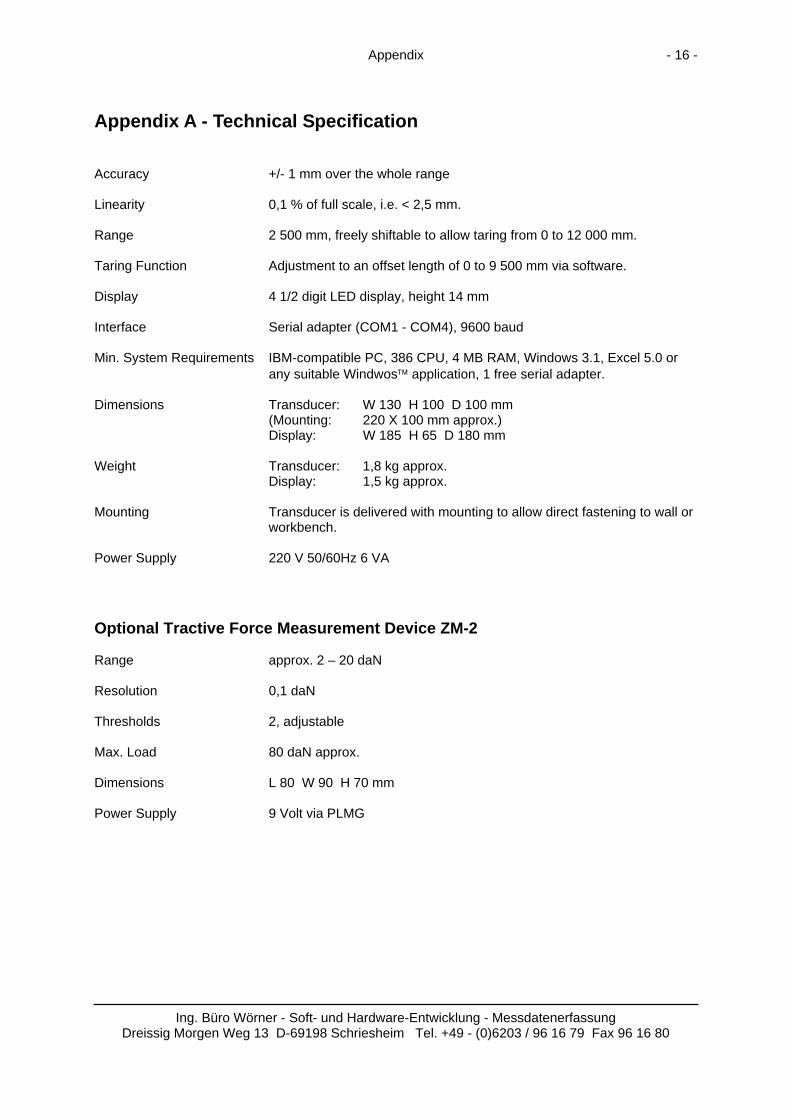
Appendix A - Technical Specification Accuracy +/- 1 mm over the whole range Linearity 0,1 % of full scale, i.e. < 2,5 mm. Range 2 500 mm, freely shiftable to allow taring from 0 to 12 000 mm. Taring Function Adjustment to an offset length of 0 to 9 500 mm via software. Display 4 1/2 digit LED display, height 14 mm Interface Serial adapter (COM1 - COM4), 9600 baud Min. System Requirements IBM-compatible PC, 386 CPU, 4 MB RAM, Windows 3.1, Excel 5.0 or
any suitable Windwos™ application, 1 free serial adapter. Dimensions Transducer: W 130 H 100 D 100 mm
(Mounting: 220 X 100 mm approx.) Display: W 185 H 65 D 180 mm
Weight Transducer: 1,8 kg approx.
Display: 1,5 kg approx. Mounting Transducer is delivered with mounting to allow direct fastening to wall or
workbench. Power Supply 220 V 50/60Hz 6 VA Optional Tractive Force Measurement Device ZM-2 Range approx. 2 – 20 daN Resolution 0,1 daN Thresholds 2, adjustable Max. Load 80 daN approx. Dimensions L 80 W 90 H 70 mm Power Supply 9 Volt via PLMG
Ing. Büro Wörner - Soft- und Hardware-Entwicklung - Messdatenerfassung
Dreissig Morgen Weg 13 D-69198 Schriesheim Tel. +49 - (0)6203 / 96 16 79 Fax 96 16 80

Appendix - 17 -
Appendix B - Connector Pinouts Switch external (3 pin): Foot Switch Switch for Backskip in Application Program
1 3
2
Ser. Data (9 pin D Type Connector): 2 - TxD (Out)
3 - RxD (In)
5 - Gnd
Ing. Büro Wörner - Soft- und Hardware-Entwicklung - Messdatenerfassung
Dreissig Morgen Weg 13 D-69198 Schriesheim Tel. 06203 / 96 16 79 Fax 96 16 80
Appendix - 18 -
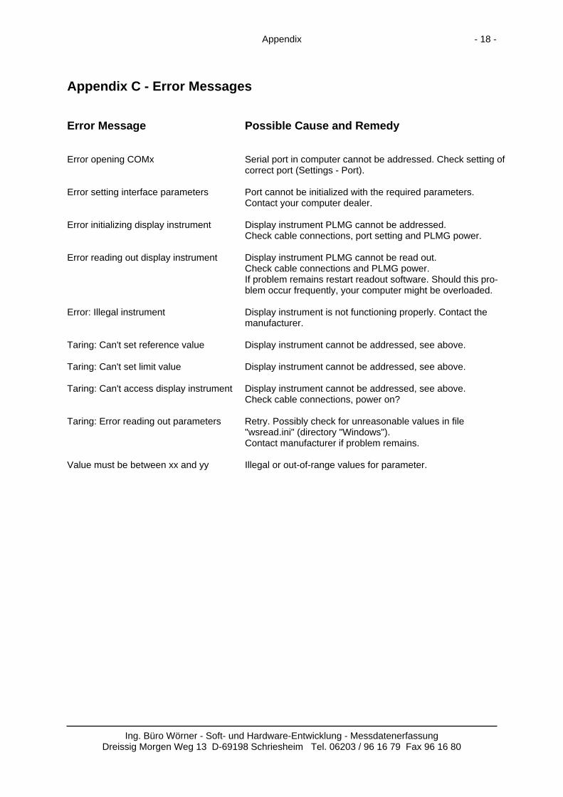
Appendix C - Error Messages Error Message Possible Cause and Remedy Error opening COMx Serial port in computer cannot be addressed. Check setting of
correct port (Settings - Port). Error setting interface parameters Port cannot be initialized with the required parameters.
Contact your computer dealer. Error initializing display instrument Display instrument PLMG cannot be addressed.
Check cable connections, port setting and PLMG power. Error reading out display instrument Display instrument PLMG cannot be read out.
Check cable connections and PLMG power. If problem remains restart readout software. Should this pro-blem occur frequently, your computer might be overloaded.
Error: Illegal instrument Display instrument is not functioning properly. Contact the
manufacturer. Taring: Can't set reference value Display instrument cannot be addressed, see above. Taring: Can't set limit value Display instrument cannot be addressed, see above. Taring: Can't access display instrument Display instrument cannot be addressed, see above.
Check cable connections, power on? Taring: Error reading out parameters Retry. Possibly check for unreasonable values in file
"wsread.ini" (directory "Windows"). Contact manufacturer if problem remains.
Value must be between xx and yy Illegal or out-of-range values for parameter.
Ing. Büro Wörner - Soft- und Hardware-Entwicklung - Messdatenerfassung
Dreissig Morgen Weg 13 D-69198 Schriesheim Tel. 06203 / 96 16 79 Fax 96 16 80

Appendix - 19 -
Appendix D - Quick Instructions ZM-2
Mounting Eye
Load Hook Specification:
Range: 0 - 80 daN (0 - 80 kp) Resolution: 0,1 daN (0,1 kp) max. Load: 100 daN (100 kp) Lower Threshold: adjustable 0 - approx. 20 daN Window Width: adjustable 0 - approx. 3 daN Power Supply: via PLMG - 9 Volts, approx. 20 mA
Principles of Measurement: The tractive force measuring device ZM-2 is designed to signal an applied force to be with an adjustable range, e.g within 50 - 60 daN (5,0 - 6,0 Kp). -> Window <-
Force too low Force too high
Force within window
0 Upper Threshold
Lower Threshold
Tractive Force
Ing. Büro Wörner - Soft- und Hardware-Entwicklung - Messdatenerfassung
Dreissig Morgen Weg 13 D-69198 Schriesheim Tel. 06203 / 96 16 79 Fax 96 16 80

Appendix - 20 -
Adjusting the Threshold Values: 1. Connect device to line measuring system or appropriate power supply. 2. Apply appropriate load for lower threshold (e.g. via weight or hand scale). 3. Adjust response of lower threshold via potentiometer 'lower threshold'. 4. Apply appropriate load for upper threshold. 5. Adjust response of upper threshold via potentiometer 'window width'. 6. Re-check lower threshold. Notice: Both potentiometers have a range of 12 turns. 1 turn thus corresponds to approx. 20 N (2 kp) for the lower threshold or 2,5 N (0,25 kp) for the window width respectively. Factory settings: 50 daN lower threshold, 10 daN window width approximately.
Lower Threshold
Window Width
Adjustment of the ZM - 2 device (Rear View)
Mounting: Attach the device to an appropriate fix point. Use shackle (paralink) or similar through mounting eye to avoid lateral forces, bending or torsion. The device should swing freely for accurate measuring. Apply measured force through load hook. Overloading the device could lead to permanent damage and inaccuarate measurements!
Mounting
Force to be measured
Ing. Büro Wörner - Soft- und Hardware-Entwicklung - Messdatenerfassung
Dreissig Morgen Weg 13 D-69198 Schriesheim Tel. 06203 / 96 16 79 Fax 96 16 80

Appendix - 21 -
Appendix E - Excel Worksheet Template
Ing. Büro Wörner - Soft- und Hardware-Entwicklung - Messdatenerfassung
Dreissig Morgen Weg 13 D-69198 Schriesheim Tel. 06203 / 96 16 79 Fax 96 16 80

Appendix - 22 -
Appendix F - Measurement Assembly
Ing. Büro Wörner - Soft- und Hardware-Entwicklung - Messdatenerfassung
Dreissig Morgen Weg 13 D-69198 Schriesheim Tel. 06203 / 96 16 79 Fax 96 16 80