HYDRONICS FOR WOOD-FIRED HEAT SOURCES an Auxiliary Boiler with an Outdoor Wood-Fired Furnace ......
56
Transcript of HYDRONICS FOR WOOD-FIRED HEAT SOURCES an Auxiliary Boiler with an Outdoor Wood-Fired Furnace ......


Caleffi North America, Inc. 9850 South 54th Street Franklin, WI 53132 T: 414.421.1000 F: 414.421.2878
Dear Hydronic Professional,
Welcome to the 2nd edition of idronics – Caleffi’s semi-annual design journal for hydronic professionals.
The 1st edition of idronics was released in January 2007 and distributed to over 80,000 people in North America. It focused on the topic hydraulic separation. From the feedback received, it’s evident we attained our goal of explaining the benefits and proper application of this modern design technique for hydronic systems.
If you haven’t yet received a copy of idronics #1, you can do so by sending in the attached reader response card, or by registering online at www.caleffi.us. The publication will be mailed to you free of charge. You can also download the complete journal as a PDF file from our Web site.
This second edition addresses air and dirt in hydronic systems. Though not a new topic to our industry, the use of modern high-efficiency equipment demands a thorough understanding of the harmful effects of air and dirt, as well as knowledge on how to eliminate them. Doing so helps ensure the systems you design will operate at peak efficiency and provide long trouble-free service.
We trust you will find this issue of idronics a useful educational tool and a handy reference for your future hydronic system designs. We also encourage you to send us feedback on this issue of idronics using the attached reader response card or by e-mailing us at [email protected].
Sincerely,
Mark Olson General Manager,Caleffi North America, Inc.
A Technical Journalfrom
Caleffi Hydronic Solutions
CALEFFI NORTH AMERICA, INC3883 W. Milwaukee Rd
Milwaukee, Wisconsin 53208 USA
Tel: 414-238-2360FAX: 414-238-2366
E-mail: [email protected]: www.caleffi.us
To receive future idronics issues FREE, register online www.caleffi.us
Dear Hydronic Professional,
Welcome to the 10th edition of idronics, Caleffi’s semi-annual design journal for hydronic professionals.
The term Biomass is often heard these days. It broadly refers to any energy source derived from recently living organisms. Common examples include methane from landfill waste, animal residues, dried corn, biodiesel fuels and ethanol. Wood is also a biomass, and a focus of this publication. As a heat source, it is renewable, widely available (especially in non-urban areas), does not require a conversion process to produce (like ethanol for example), and has physical properties compatible to both residential and commercial heating.
Over the past 30 years, engineering advancements in wood-fired heating systems have led to improved energy efficiencies and dramatically reduced emissions. As a result, wood systems have experienced renewed popularity in North America. Coupled with increased public environmental awareness, wood-fired boilers and furnaces have the potential for significant growth in the coming years.
A key enabler for widespread adaption, however, is that wood systems must reliably deliver heat when and where it is needed within a facility. Hydronics is the best technology available for accomplishing this. In this issue, we explain how to leverage state-of-the-art hydronics technology with today’s various wood-burning devices to provide maximum comfort, efficiency, safety and convenience.
We encourage you to send us feedback on this issue of idronics by e-mailing us at [email protected].
If you are interested in previous editions of idronics, please go to www.caleffi.us where they can be freely downloaded. You can also register online to receive future hard copy issues.
Mark OlsonGeneral Manager & CEO
3 INTRODUCTION Brief History of Wood Burning and Hydronics
5 WOOD AS A HEATING FUEL Energy Contained in Wood Processed Wood Fuel Creosote
9 WOOD-FIRED HYDRONIC HEAT SOURCES Outdoor Wood-Fired Furnaces Wood-Fired Boilers Wood-Gasification Boilers Pellet-Fired Boilers
13 HEAT EMITTERS FOR WOOD-FIRED SYSTEMS Heated Floor Slabs Heated Thin-Slabs Other Site-Built Radiant Panels Panel Radiators Low-Temperature Fin-Tube Baseboard Cast Iron Radiators
18 SYSTEMS USING OUTDOOR WOOD-FIRED FURNACES Open-Loop Considerations Hybrid Open/Closed Systems Other Design Considerations Using an Auxiliary Boiler with an Outdoor Wood-Fired Furnace Freeze Protection Options
24 DESIGN DETAILS FOR WOOD-FIRED BOILER SYSTEMS Protecting Against Corrosion Protection Against Sustained Flue Gas Condensation Combining a Wood-Fired Boiler with an Auxiliary Boiler Buffer Tanks Unpressurized Buffer Tanks Pressurized Buffer Tanks Buffer Tank Sizing
36 EXAMPLES OF WOOD-FIRED BOILER SYSTEMS System 1: Heating Only with Extensive Zoning System 2: Heating & Domestic Hot Water with Extensive Zoning System 3: Heating & Domestic Hot Water with Large Buffer Tank System 4: Heating & Domestic Hot Water with Solar Supplemental Heating System 5: Heating & Domestic Hot Water with Geo Heat Pump Supplemental Heating System 6: Pellet-Fired Boiler Supplying Heating and Domestic Hot Water System 7: Pellet-Fired Boiler Supplying Heating and Domestic Hot Water with Extensive Zoning System 8: Wood-Fired Boiler Auxiliary Furnace
45 SUMMARY
46 Appendix A: Piping Symbol Legend47 Appendix B: Expansion Tank Sizing for Closed-Loop Systems
Caleffi North America, Inc.3883 W. Milwaukee RdMilwaukee, Wisconsin 53208T: 414.238.2360 F: 414.238.2366
10%
Cert no. XXX-XXX-XXXX
© Copyright 2011 Caleffi North America, Inc.
Printed: Milwaukee, Wisconsin USA
INDEX
Disclaimer: Caleffi makes no warranty that the information presented in idronics meets the mechanical, electrical or other code requirements applicable within a given jurisdiction. The diagrams presented in idronics are conceptual, and do not represent complete schematics for any specific installation. Local codes may require differences in design, or safety devices relative to those shown in idronics. It is the responsibility of those adapting any information presented in idronics to verify that such adaptations meet or exceed local code requirements.
3
1. INTRODUCTION
Humans have used wood as a heating fuel for centuries. Its availability, or scarcity, has shaped the development of civilization from its earliest origins. Until the development of methods for extracting and transporting fossils fuels and electricity, wood was the staple for heating American homes, as well as those in other parts of the world. During this time, nearly all North American homes were constructed with one or more wood-burning fireplaces or stoves. Many had “woodsheds” attached to or located close by, which were filled and emptied on an annual basis. Harvesting wood for fuel was a common as harvesting crops for food.
The history of civilization, dating back to ancient Greece, shows a recurring pattern of humans using the most available and easily attained fuel. In many cases, that fuel was wood. When depletion of the local wood supply reached a point where convenience, cost or transportation logistics precluded further exploitation, attention turned to other fuel sources such as direct use of solar energy. This is not surprising, but rather a logical response to an immediate and inescapable reality—the need to maintain life under ambient conditions that would otherwise quickly extinguish human existence.
As interstate transportation systems were developed for petroleum and natural gas, wood was increasingly viewed as an antiquated heating fuel. This perception was further reinforced by the fact that oil, gas and electrical heat sources provided automatic operation, freeing occupants to pursue other activities rather than tending to wood-fired heating devices. To many people, home heating became as simple as turning a thermostat dial to the desired temperature and paying a monthly fuel bill. This convenience obviously appealed to those who had spent years cutting, splitting and carrying firewood. Petroleum companies and utilities focused their marketing on persuading homeowners to “modernize” to fully automatic heating using oil, gas and electricity. At the time there was virtually no concern about the long-term sustainability or ecological consequences associated with heating buildings.
Civilization has reached a point where the worldwide effects of energy options are better understood, rapidly communicated and more accurately extrapolated into the future. Looking beyond political or organizational agendas, it seems obvious that increasing population imposes tightening constraints that must be respected if quality of life is to be maintained or improved. One of the most pressing of those constraints is establishing sustainable energy supplies.
This led to renewed interest in wood as a heating fuel. The fact that wood is “carbon neutral” (i.e., its use as fuel only releases the carbon that was embodied into the wood as it was produced through photosynthesis) is a benefit that is now viewed as highly desirable. This along with modern technologies that can convert the chemical energy stored in wood into thermal energy with efficiencies of 90+ percent have sparked worldwide interest in wood as a “rediscovered” fuel for central heating.
This issue of idronics was written to show heating professionals how to leverage modern hydronics to enhance the performance of wood-fueled heat sources. It examines devices that use cordwood as well as wood pellets. It also presents system schematics that allow wood-fired heat sources to be combined with other devices that can augment the energy derived from the wood.
The ability to efficiently and reliably deliver heat precisely when and where it is needed within a building remains a prerequisite to broad acceptance of wood as a heating fuel. Hydronics is the premier technology for doing this.
BRIEF HISTORY OF WOOD BURNING AND HYDRONICSEarly attempts at combining wood-burning devices with hydronic distribution systems produced mixed results. In response to the oil embargo of the early ’70s, early
HYDRONICS FOR WOOD-FIRED HEAT SOURCES
Figure 1-1

4
hydronic-based wood-burning devices were developed with little if any engineering or testing. Instead they could be described as rudimentary heat exchangers attached to or placed within fireplaces or wood stoves. The fireplace grate seen in Figure 1-2 is an example.
Source: Mother Earth News
The combustion efficiency and heat transfer ability of these devices was often limited by existing material or shape constraints, and they degraded rapidly due to formation of creosote or accumulation of ash. Such devices appealed to those looking for quick solutions, but at the same time being unaware of the principals necessary for efficient combustion, good heat transfer or product longevity. The lackluster performance of some early devices combined with safety issues discouraged further expansion of the market.
During the ’70s, several wood stove manufacturers added interior water-filled heat exchange grates to their products. As with fireplaces, these devices were developed as add-on options and were usually constrained by the proportions of the stove. They also experienced performance issues associated with creosote and ash accumulation.
Another wood-burning product that developed in North America over the last three decades is known as an outdoor wood-burning “furnace.” Such devices resemble a small, steel storage building, as shown in Figure 1-3. They are usually located several yards away from the building(s) to which they supply heat. During cold weather, they operate
with a continuously maintained fire and transfer heat into a water-filled compartment that surrounds the combustion chamber. The heated water is circulated through underground piping to a heat exchanger inside the building. The large combustion chamber can hold enough wood to sustain the fire for several hours.
The current state-of-the art in wood-fired combustion is wood gasification. This describes the process of heating wood in the absence of sufficient oxygen for combustion. The pyrolytic gases emitted by the wood under these conditions contain chemical energy that can be efficiently extracted through controlled combustion in oxygen-rich environments. An example of a modern wood-gasification boiler is shown in Figure 1-4.
Courtesy of Dunkirk Metal Products
Wood gasification dates back to the 1920s. Early gasifiers were used to generate synthetic gases along with lesser amounts of carbon dioxide and hydrogen. This gas was then used to operate stationary internal combustion engines, and occasionally even to power automobiles.
Figure 1-5 shows the secondary combustion chamber of a modern wood gasification boiler. The flame in this chamber can be likened to that of a blow torch. Combustion temperatures over 2000ºF can be achieved. The result is a highly efficient conversion from chemical
Figure 1-2
Figure 1-3
Figure 1-4

5
to thermal energy and minimal formation of ash. Modern wood gasification boilers also provide better control of heat output relative to non-gasification combustion devices. Later sections of this manual show how to leverage this high efficiency using modern hydronics technology.
Courtesy of Dunkirk Metal Products
2. WOOD AS A HEATING FUEL
Wood is one form of biomass. With proper forestry practices, it is a fully renewable energy source. In some regions, there is even an excess of non-lumber grade wood accumulating in forests. Harvesting this wood for fuel reduces the risk of forest fires and improves forest health. Wood is also considered a “carbon neutral” energy source. Burning it only releases the carbon that accumulated as the wood grew. Wood also has very low sulfur content. Its combustion does not contribute to atmospheric accumulation of sulfur oxides, a cause of acid rain.
In many locations, wood is an indigenous energy source. It seldom requires interstate transportation as do other energy sources. Its use as a fuel usually keeps dollars in the local economy. Its use also reduces dependency on foreign energy suppliers and thus adds to national and economic security.
ENERGY CONTAINED IN WOODOne of the most important measures of any fuel is the chemical energy contained within a given mass or volume. The BTU content of several common energy sources used for heating residential and light commercial buildings is a follows:
• #2 fuel oil: 138,500 Btu/gallon• Waste oil: 125,000 Btu/gallon• Natural gas: about 1030 Btu/ cubic foot• Propane: 92,500 Btu per gallon• Electricity: 3413 Btu/ kilowatt-hour • Hard coal (anthracite): 26,000,000 Btu/ton
The fuel energy contained in oven-dried mature wood is approximately 7950 Btu per pound. This value is based on weight rather than volume, and is valid for both hardwoods and softwoods. The latter are less dense, and thus a given volume of softwood contains less fuel energy than an equal volume of hardwood.
The fuel energy of 7950 Btu/lb is only attainable in wood that has been oven dried to zero moisture content. The lower heating value of wood with other moisture contents can be approximated by the Formula 2-1.
Formula 2-1:
Where:LHV = Lower heating value (Btu/lb)*w = moisture content (%)
*Lower heating value does not include the latent heat associated with water vapor produced as the wood is burned.
Thus, wood with 20% moisture content, typical of firewood that’s been keep under cover and air dried for at least nine months, is approximately:
The greater the moisture content, the lower the available heat. This is a result of having to evaporate moisture during the combustion process. Evaporating water requires a
Figure 1-5
Figure 2-1

6
substantial amount of energy (970 Btu/lb). That energy comes from combustion of the wood, and as such, is not available for heating other materials. Thus, to attain the greatest fuel value, all wood should be as dry as possible. Freshly cut “green” wood can contain 70% to 100% more moisture than properly dried, “seasoned” firewood. The moisture content for wood that has been air dried under cover for at least nine months ranges from 20% to 25%.
In North America, firewood is typically sold by volume. Two common units are used:
• Full cord: refers to a volume of neatly stacked, split wood that measures 4 feet high by 8 feet long by 4 feet deep.
• Face cord: Refers to a volume of neatly stacked, split wood that measures 4 feet high by 8 feet long by 16 inches deep.
Neither of these definitions is precise in the sense that repeatedly stacking the same firewood will always produce slightly different overall stack dimensions. Still, these units have been used in the North American firewood industry so long that some people refer to firewood as “cordwood.”
Although the fuel value of a pound of hardwood versus a pound of softwood having the same moisture content is approximately equal, the density of various woods will significantly affect the energy contained in the same volume (e.g., full cord or face cord). Figure 2-3 lists the approximate lower heating value contained in a full cord of several different species of wood, all with an assumed 20% moisture content.
* 1 MMBtu = 1,000,000 Btu
PROCESSED WOOD FUELAlthough firewood is the most recognized form of wood fuel, advances in wood processing have made other forms of wood fuel more readily available over the last two decades. New methods for transporting and burning processed wood fuel have been developed.
One of the newest forms of processed wood fuel is wood pellets. They can be burned in a wide variety of devices including stoves, furnaces and boilers.
Wood pellets are produced from wood chips and/or sawdust. The chips are shredded into small fibers, dried to approximately 10% moisture content and then forced through an extrusion device under very high (60,000 psi) pressure. This extreme pressure forces the natural resins within the wood cells to act as a bonding agent for the fibers. No other bonding agents are required. The extruded cylinders of compressed and bonded wood fiber with a nominal 1/4-inch diameter randomly break into small pieces (e.g., pellets) as they exit the extrusion machine.
Figure 2-2
Figure 2-3
Figure 2-4

7
After manufacturing, pellets are easily handled by pneumatic and auger transport systems. They can be stored and transported by equipment similar to that used for pelletized animal feeds. As such they lend themselves to existing infrastructures for mass production and transportation.
One of the biggest advantages of pellet-fired boilers is that the combustion process can be turned on and off, as well as modulated when necessary. This allows the output of a pellet-fired boiler to better match the heating needs of a building without need of a larger thermal storage tank. High-quality wood pellets also reduce particulate emissions relative to firewood.
Another recently developed form of processed wood fuel is known as briquettes, as seen in Figure 2-5.
These briquettes are made of shredded and dried wood fiber similar to that used for pellets. The fiber is compressed under very high pressure sufficient to force the natural resins within the wood cells to bond the fibers together.
No other bonding additives are needed. The resulting briquettes are very hard and dense. One pound of compressed wood fiber in a briquette has a fuel value equivalent to 1.7 pounds of firewood. Wood briquettes are also very “clean” relative to standard firewood, and thus appeal to those who don’t want the dirt and dust associated with handling conventional firewood inside a home.
Wood briquettes can be efficiently transported on tightly packed pallets and must be stored away from sources of moisture. They are manually fed to the wood-burning heat source.
Wood chips are another form of processed wood fuel. They are made by grinding pieces of wood or non-lumber-grade “cull” logs into small flat pieces, as shown in Figures 2-6 and 2-7. Most wood chips are not kiln dried, and as such, contain significantly more moisture (40% to 50% moisture) compared to wood pellets (10% moisture). Unlike the more uniform consistency of pellets, wood chips can vary widely in size. Because of how they are made, wood chips are often mixed with twigs and sawdust. They are not as easily conveyed by rotating augers as wood pellets. In
Source: BioPellet LLC
Figure 2-5
Figure 2-6
Figure 2-7
Source: Wikipedia.org
Figure 2-8
Source: Biomasscenter.org
8
larger installations, wood chips are moved from a storage pile using a front-end loader and fed to the boiler by a conveyor belt (see Figure 2-7). At present, most wood chip boilers are designed for larger commercial or institutional buildings where the cost and logistics of chip storage and handling are justified in relationship to the energy produced.
The energy content of wood that has been processed into pellets, chips or sawdust is typically expressed as MMBtu/ton. One MMBtu = 1,000,000 Btu. Typical values are given in figure 2-9:
Like any fuel, the lower heating value only indicates the theoretical energy yield if that fuel could be combusted and transferred to some other media at 100% efficiency. The actual heat delivered to a heating distribution system by a wood-fired heat source is highly dependent on the wood used for fuel (primarily its moisture content), as well as how the combustion process is managed. Efficiencies can range from as high as 92% in a wood gasification boiler burning seasoned wood, to as low as 20% in a device with oxygen-starved combustion burning high-moisture wood. Conditions that increase the temperature of the combustion process also increase the efficiency of a wood-fired heat source.
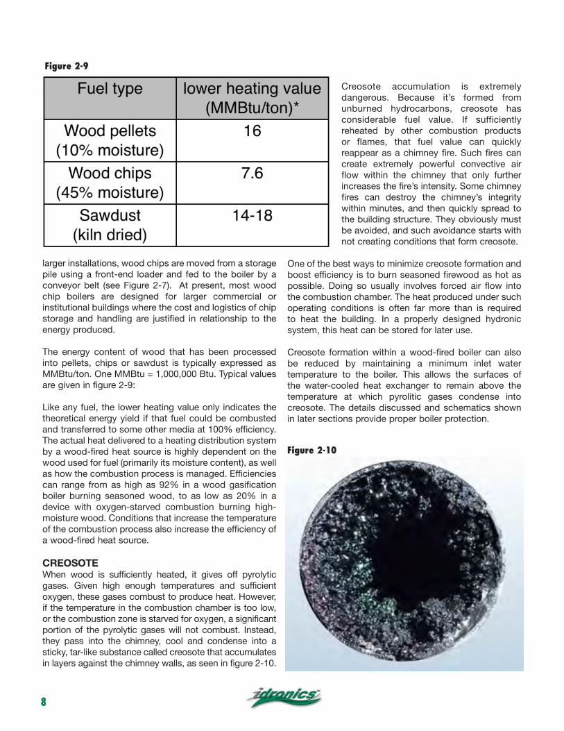
CREOSOTEWhen wood is sufficiently heated, it gives off pyrolytic gases. Given high enough temperatures and sufficient oxygen, these gases combust to produce heat. However, if the temperature in the combustion chamber is too low, or the combustion zone is starved for oxygen, a significant portion of the pyrolytic gases will not combust. Instead, they pass into the chimney, cool and condense into a sticky, tar-like substance called creosote that accumulates in layers against the chimney walls, as seen in figure 2-10.
Creosote accumulation is extremely dangerous. Because it’s formed from unburned hydrocarbons, creosote has considerable fuel value. If sufficiently reheated by other combustion products or flames, that fuel value can quickly reappear as a chimney fire. Such fires can create extremely powerful convective air flow within the chimney that only further increases the fire’s intensity. Some chimney fires can destroy the chimney’s integrity within minutes, and then quickly spread to the building structure. They obviously must be avoided, and such avoidance starts with not creating conditions that form creosote.
One of the best ways to minimize creosote formation and boost efficiency is to burn seasoned firewood as hot as possible. Doing so usually involves forced air flow into the combustion chamber. The heat produced under such operating conditions is often far more than is required to heat the building. In a properly designed hydronic system, this heat can be stored for later use.
Creosote formation within a wood-fired boiler can also be reduced by maintaining a minimum inlet water temperature to the boiler. This allows the surfaces of the water-cooled heat exchanger to remain above the temperature at which pyrolitic gases condense into creosote. The details discussed and schematics shown in later sections provide proper boiler protection.
Figure 2-9
Figure 2-10

9
3. WOOD-FIRED HYDRONIC HEAT SOURCES
This section provides an overview of several types of wood-fired hydronic heat sources. They range from outdoor wood-fired furnaces to sophisticated pellet-fired boilers. A summary discussion of the operating characteristics of these heat sources helps designers make decisions on how best to integrate them with the balance of the system.
OUTDOOR WOOD-FIRED FURNACESOne approach to heating with wood keeps both the firewood and the fire outside the buildings being heated. This can be done using an outdoor wood-fired furnace. This approach has the following benefits:
• It is inherently safer since the fire and fuel are not inside the building.
• The dirt, smell and insects associated with bringing firewood inside are eliminated.
• Placement of relatively large and heavy heat sources is simpler outside than inside.
• Very little interior space is required for this approach.
Most outdoor wood-fired furnaces are unpressurized devices in which a water-filled compartment surrounding the combustion chamber is vented to the atmosphere, as shown in Figure 3-1. As such, these devices cannot be classified as boilers.
Most outdoor wood-fired furnaces have thermostatically controlled blowers and air dampers that provide some control over heat output. Their fireboxes can hold a large “charge” of wood. Thus, they typically only need to be refueled one or two times in a 24-hour period, depending on the heating load. On larger units, the water compartment may hold several hundred gallons. This gives the unit considerable thermal mass that can often supply heat to the building for several hours after the fire has subsided.
Freeze protection is usually accomplished by continuously circulating water between the outdoor furnace and the building it serves. This approach assumes that electrical energy is available to operate the circulator, and that sufficient heat from within the building can be transferred to the circulating water as it passes though the interior portion of the system. Some designers consider this a risky approach, especially in cold winter climates. Antifreeze could be used, but the large water compartment makes this an expensive option.
The thermal efficiency of outdoor wood-fired furnaces is significantly lower than other wood-burning heat sources. The efficiency of a given unit depends on how it is operated, but average efficiencies in the range of 35% to 50% are typical. The use of cold firewood with moisture content greater than 20% will decrease efficiency and increase creosote formation.
Some municipalities have enacted laws that significantly restrict or even ban the use of outdoor wood-fired furnaces. The primary concern is avoiding smoke plumes that, under certain conditions, do not rise sufficiently above the low chimneys often used with these devices, as seen in Figure 3-2.
insulated underground piping
vent to atmosphere
!circulator
loading!door
ash!door
water!compartment
chimney
!firebox
!concrete base
insulated!shell
Figure 3-1
Figure 3-2

10
Low-hanging smoke can drift toward buildings, move over neighboring properties or drift across roads, causing pollution as well as safety issues. In some cases, it is necessary to install a tall chimney adjacent to the outdoor furnace to lift smoke to a height where it will not impact adjacent buildings. Due to such concerns and requirements, outdoor wood-fired furnaces are obviously more practical in rural locations.
Although outdoor wood-fired furnaces do not represent state-of-the-art wood combustion technology, there are tens of thousands of them in use in North America, and they remain available in many locations. Later sections of this issue show how outdoor furnaces can be used in combination with pressurized hydronic distribution systems.
WOOD-FIRED BOILERSAnother category of wood-fired heat sources is wood-fired boilers. Unlike outdoor furnaces, these boilers have pressure-rated water compartments and are designed to operate in closed-loop pressurized systems, much like oil- or gas-fired boilers.
Some wood-fired boilers are designed to draw air from the space around them using only the draft created by their chimney. These so-called “atmospheric” wood-fired boilers are typically constructed with cast iron sections. An example of such a boiler is shown in Figure 3-3.
This boiler uses “wet-base” cast iron sections that surround the combustion chamber. Wood is loaded in the upper chamber, and ash is periodically removed from the bottom of this chamber through the lower door.
The lower door also has a hinged damper plate that controls the flow of air into the combustion chamber, as seen in Figure 3-4. The position of this damper is regulated by a non-electric thermostatic regulator that senses boiler water temperature. As the water temperature near the top of the boiler decreases below its setpoint, the thermostatic regulator lifts a light chain that opens the air damper to increase the rate of combustion. The thermostatic regulator can be adjusted over a range of temperature.
WOOD-GASIFICATION BOILERSThe current state-of-the-art technology for wood-fired boilers is wood gasification. A typical wood gasification boiler is shown in Figure 3-5.
These boilers are started much like an atmospheric wood boiler, using kindling and smaller pieces of firewood in the boiler’s upper chamber with an upward draft. However, once the fire in the upper chamber is stable, the firebox is loaded to capacity, the upper damper is closed and a blower turns on to redirect the pyrolitic gases being emitted by the heated wood in a downward direction, as shown in Figure 3-6.
These gases pass through a slot in a ceramic grate at the base of the combustion chamber. Air, pressurized by the blower, is also forced through holes in the side of this slot and Courtesy of QHT, Inc.
thermostatic!regulator
air damper
chai
n
combustion!air
Figure 3-3
Figure 3-4

11
mixes with the hot gases. The resulting combustion is intense, often reaching temperatures over 2000ºF and having the appearance of a blow torch, as seen in Figure 3-7. This form of combustion results in very little residue.
The variable-speed blower in a wood gasification boiler regulates the rate of combustion based on the water temperature in the boiler. As the water temperature approaches a set upper limit, the blower’s speed is reduced.
The highest combustion efficiency is achieved by burning a full load of wood at the maximum possible rate. This usually results in heat being produced at a rate greater than that required by the load. This mismatch is a common characteristic of wood-fired heating systems. It is further exacerbated by zoned hydronic distribution systems.
The solution is to include a well-insulated buffer tank in any system using a wood-gasification boiler. This tank absorbs any heat output that exceeds the current load. When necessary, it can also release heat to the load at rates significantly greater than the current output from the boiler. Options for such tanks will be discussed in later sections.
PELLET-FIRED BOILERSBecause of the size and handling methods for fuel, pellet-fueled boilers are very different from boilers that burn firewood. Most have two major subassemblies: One consisting of a hopper and auger system to automatically feed pellets into the “burn pot,” and the other consisting of a combustion chamber, fire-tube heat exchanger and ash management hardware. A cut-away of a modern pellet-fueled boiler appropriate for residential or light commercial hydronic systems is shown in Figure 3-8.
The “day-hopper” seen on the right side of Figure 3-8 can hold enough pellets for several hours of unattended operation. The hopper can be manually loaded by pouring in two or three 40-pound bags of pellets, or it can be automatically loaded with pellets from a bulk storage device. Such devices include bag silos, underground storage tanks and bins, as shown in Figure 3-9.
Bulk storage systems for pellets use combinations of motor-operated augers and pneumatic tubing systems to move pellets from bulk storage to the day-hopper. The air pressure differential needed to move pellets through pneumatic tubing is created by a blower in the day-hopper.
Courtesy of New Horizons Corporation
primary air
secondary air
blower
damper !(closed during gasification)
firetubes w/ turbulators
ceramic!grates
Courtesy of New Horizon Corp.
Figure 3-5
Figure 3-6
Figure 3-7

12
Bulk supply systems are periodically filled from a delivery truck and allow a pellet-fueled boiler to operate unattended for weeks. The only manual intervention is occasional removal of fly ash from the lower compartment on the boiler. The ash produced by high-quality “premium” wood pellets is less than 1%of the pellet’s original volume. Ash is typically removed from the boiler every two to four weeks depending on usage and the quality of pellets burned.
Unlike boilers that burn firewood, pellet boilers can automatically start when there is a demand for heat. The startup process begins when a motorized auger loads a quantity of pellets into the burn pot. They are then ignited using superheated air or a ceramic heating element. Once started, the combustion process is regulated using oxygen-sensing devices in the combustion stream to control a variable-speed combustion air blower speed. This technology minimizes excess air and can yield combustion efficiencies of 90% or more. Modern pellet-fueled boilers can also modulate heat output over a limited range. However, a buffer tank is still recommended, especially if the hydronic distribution system supplied by the boiler is extensively zoned.
The exhaust gases from pellet boilers contain water vapor. Such boilers should only be vented through stainless steel or other approved piping. Always follow the boiler manufacturer’s instructions for venting and combustion air requirements.
pellet transport!suction blower
day hopper
pellet queue
slider gate
auger drive
ignition!assembly
ash drawer
burn pot
flue gas tubes!w/ rotating
cleaning assembly
exhaust blower
controls
vent connector
water!compartment
Figure 3-8
Figure 3-9
Courtesy of Tarm Biomass.
Courtesy of Tarm Biomass.

13
4. HEAT EMITTERS FOR WOOD-FIRED SYSTEMS
Hydronic distribution systems that operate with low water temperatures are preferred in wood-fired boiler systems, especially those systems with high water content. The lower the temperature at which distribution systems can deliver heat, the longer the wood-fired boiler and its associated thermal storage can supply heat before refueling. Lower water temperatures also allow for smaller buffer tank volumes since they extend the lower end of the temperature cycling range. Finally, low water temperatures increase the thermal efficiency of supplemental or auxiliary heat sources such as solar thermal collectors, heat pumps or modulating/condensing boilers.
Space-heating distribution systems that provide design (i.e., maximum) heating load output using supply water temperatures no higher than 120ºF are suggested as a reasonable design criteria.
Distribution systems that supply each heat emitter using parallel piping branches rather than series configurations are also preferred because they provide the same supply water temperature to each heat emitter.
Examples of space-heating systems that allow wood-fired hydronic heat sources to provide good performance include:
• Heated floor slabs with low-resistance coverings• Heated thin-slabs over framed floors with low-resistance coverings• Heated walls or ceilings• Generously sized panel radiator systems with parallel piping• High output fin-tube baseboard
Each of these will be presented in more detail.
HEATED FLOOR SLABS Heated floor slabs with relatively close tube spacing and low finish floor resistances are generally well suited for use with wood-fired heat sources. Figure 4-1 shows an appropriate cross section. Notice that the tubing has been placed at approximately mid-depth within the slab, and that the underside and edge of the slab are well insulated. Both of these
details are imperative in achieving good low-temperature performance.
The graph in Figure 4-2 shows upward heat output from a heated slab based on tube spacing of 6 inches and 12 inches, and for finish floor resistances ranging from 0 to 2.0 (ºF•hr•ft2/Btu). The steeper the line, the lower the water temperature required for a specific rate of heat delivery.
For example, achieving an upward heat output of 20 Btu/hr/ft2 from a slab with no covering (e.g., Rff = 0) and 6-inch tube spacing requires the “driving ∆T” (e.g., the difference between average water temperature in tubing and room air temperature) to be 17.5ºF. Thus, in a room maintained at 70ºF, the average water temperature in the circuit needs to be 87.5ºF. The supply water temperature to the circuit would likely be in the range of 95–98ºF. This is a relatively low supply water temperature, and should allow buffer tanks associated with wood-fired or pellet-fired boilers to supply heat for longer periods without refueling.
For comparison, consider supplying the same 20 Btu/hr/ft2 load using a heated floor slab with 12-inch tube spacing and a finish floor resistance of 1.0ºF•hr•ft2/Btu. The
underslab insulationsteel reinforcing
embedded tubingfinish flooring
polyethylene vapor barrier
concrete slab
foundation
edge insulation
compacted soil
Figure 4-1

14
driving ∆T must now be 42.5ºF. The average circuit water temperature required to maintain a room temperature of 70ºF would be 70 + 42.5 = 112.5ºF, and the supply temperature would be likely in the range of 120º–123ºF. This higher temperature could be produced by wood-fired boilers, but would limit the lower temperature of the buffer tank, and thus require more frequent refueling.
The following guidelines are suggested in applications where a heated floor slab will be used to deliver heat derived from a wood-fired hydronic heat source:
• Tube spacing within the slab should not exceed 12 inches.• Slab should have minimum of R-10 underside and edge insulation.• Tubing should be placed at approximately half the slab depth below the surface, as shown in Figure 4-2. Doing so decreases the required water temperature required for a given rate of heat output. Lower water temperatures improve heat source performance.• Bare, painted or stained slab surfaces are ideal because the finish floor resistance is essentially zero.• Other floor finishes should have a total R-value of 1.0 or less.
HEATED THIN-SLABSAnother common method of installing floor heating uses a “thin slab” (1-1/2-inch to 2-inch thickness) poured over a wooden floor deck. Figure 4-3 shows an example of such an installation, awaiting placement of the slab material.
Courtesy of Harvey Youker
Because the slab is thinner than with slab-on-grade floors, it has slightly lower lateral heat dispersal characteristics. This translates into a slightly higher water temperature requirement for a given rate of heat output relative to that required for a slab-on-grade. This difference is slight. A 1-1/2-inch-thick concrete thin slab with 12-inch tube spacing and covered with a finish flooring resistance of 0.5ºF•hr•ft2/Btu yields about 8% less heat output than a 4-inch-thick slab with the same tube spacing and finishing flooring. This can be easily compensated for by using 9-inch rather than 12-inch tube spacing.
The following guidelines are suggested:
• Tube spacing within the thin slab should not exceed 9 inches.• Slab should have minimum of R-19 underside insulation.• Floor finishes should have a total R-value of 1.0 or less.• Never use “lightweight” concrete for heated thin slabs.
OTHER SITE-BUILT RADIANT PANELSRadiant panels can be integrated into walls and ceilings as well as floors. Several of these configurations may be suitable for use with wood-fired hydronics systems. The key is ensuring that the radiant panel can deliver design load output while operating at a relatively low water temperature. This helps ensure the thermal storage associated with the wood-fired boiler can be discharged to the lowest possible temperature before the boiler must be refueled.
This criterion favors radiant panels that have high surface areas relative to the rate of heat delivery. It also favors panels that have relatively low internal resistance between the tubing and the surface area releasing heat to the room.
0
20
40
60
0 10 20 30 40 50 60 70 80 90 100
upw
ard
heat
flux
!(B
tu/h
r/ft
2)
Driving ∆T (Tw-Tr) (ºF)!Average water temp. - room air temp
6-inch tube spacing12-inch tube spacing
Rff=0 Rff=0.5
Rff=1.0
Rff=1.5Rff=2.0
Upward heat output !vs.!
Driving ∆T!for 4" concrete slab
Rff = resistance of finish flooring (ºF/hr/ft^2/Btu)
Figure 4-2 Figure 4-3

15
One example is a radiant wall panel constructed as shown in Figure 4-4.
When finished, this “radiant wall” is indistinguishable from a standard interior wall. Its low thermal mass allows it to respond quickly to changing internal load conditions or zone setback schedules. The rate of heat emission to the room is approximately 0.8 Btu/hr/ft2 for each degree Fahrenheit the average water temperature in the tubing exceeds room air temperature. Thus, if the wall operates with an average water temperature of 110ºF in a room with 70ºF air temperature, each square foot of wall would release about 0.8 x (110 - 70) = 32 Btu/hr/ft2. This performance makes it well suited for use with wood-fired hydronic heat sources.
Another possibility is a radiant ceiling using the same type of construction as the radiant wall, as shown in Figure 4-5.
As with the radiant wall, this radiant ceiling has low thermal mass and responds quickly to interior temperature changes. Heated ceilings
wooden nailer (@ end of wall)
1/2" PEX-AL-PEX tubing (8-inch spacing)
3/4" foil-faced polyisocyanurate foam strips7/16" oriented strand board
6" x 24" aluminum heat transfer plates
7/16" oriented strand board3/4" foil-faced polyisocyanurate insulation
2.5" drywall screws
6"x24" aluminum heat transfer plates
1/2" PEX-AL-PEX tubing1/2" drywall
fiberglass insulation
cross section
1/2" drywall3/4" foil-faced polyisocyanurate foam strips
aluminum heat transfer platetube 7/16" oriented strand board
top side insulation ceiling framing
thermal image of ceiling in operation
Figure 4-4
Figure 4-5

16
also have the advantage of not being covered or blocked by coverings or furniture, and thus are likely to retain good performance over the life of the building.
For the construction shown in Figure 4-5, the rate of heat emission is approximately 0.71 Btu/hr/ft2 for each degree Fahrenheit the average water temperature in the tubing exceeds room air temperature. Thus, if the ceiling operated with an average water temperature of 110ºF in a room with 70ºF air temperature, each square foot of wall would release about 0.71 x (110 - 70) = 28.4 Btu/hr/ft2. This performance makes the radiant ceiling well suited for use with a wood-fired hydronic heat source.
PANEL RADIATORSGenerously sized panel radiators can also provide good performance when used as part of a wood-fired or pellet-fired hydronic system. Again, the suggested guideline is to size panels so they can deliver design space-heating output using a supply water temperature no higher than 120ºF. An example of a panel radiator with integral thermostatic radiator valve is shown in Figure 4-6.
Manufacturers provide output ratings for their panel radiators in either tabular or graphical form. In many cases, “reference” heat output ratings for a given size panel are stated along with corresponding water temperature and room air temperatures. Correction factors are then given,
thermostatic!radiator valves!(TRV) on each!
radiator
pressure !regulated!circulator
TRV
TRV
TRV
TRV
TRV
TRV
Figure 4-6
Figure 4-7
17
which, when multiplied by the reference heat output, give the actual heat output for specific water and room air temperatures. As an approximation, a panel radiator operating with an average water temperature of 110ºF in a room maintained at 68ºF, provides approximately 27% of the heat output it yields at an average water temperature of 180ºF. Lager panels (longer, taller and deeper) are available to increase surface area to compensate for lower operating temperatures.
For the best low-temperature performance, panel radiators should be piped in parallel. Ideally, each panel radiator is served by its own supply and return piping. A manifold-based distribution system, as shown in Figure 4-7, uses small diameter PEX or PEX-AL-PEX tubing to supply each radiator. Tube sizes in such systems varie from 3/8-inch to 5/8-inch depending on flow rate and head loss allowances.
The flow of heated water through each panel radiator is regulated by a wireless thermostatic valve, as seen mounted on the radiator in Figure 4-7. This allows each room to respond to the currently set comfort requirements, as well as to compensate for heat gain from sun or other internal heat sources.
A pressure-regulated circulator that can be set to maintain a constant differential pressure is ideal for such a distribution system. Such circulators will automatically adjust their speed in response to radiator valves opening or closing. They provide just the flow needed at any given time and significantly reduce electrical power consumption relative to fixed-speed circulators.
This type of distribution system is shown in several schematics in later sections.
LOW-TEMPERATURE FIN-TUBE BASEBOARDThe hydronics industry, worldwide, is keenly aware that low-temperature heat sources will be increasingly common in future systems. This has led to reconfigurations of traditional products in ways that allow them to operate at lower water temperatures. Few products have been more traditional to North American hydronics than fin-tube baseboard.
Fin-tube baseboard was originally developed for the high water temperatures available from conventional boilers. These baseboards are often sized based on supply water temperatures ranging from 170º to 200ºF. This is higher than the water temperatures that can be sustained for many hours by wood-fired boilers. Thus, traditional fin-tube baseboard is not recommended in such applications.
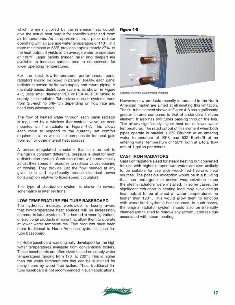
However, new products recently introduced in the North American market are aimed at eliminating this limitation. The fin-tube element shown in Figure 4-8 has significantly greater fin area compared to that of a standard fin-tube element. It also has two tubes passing through the fins. This allows significantly higher heat out at lower water temperatures. The rated output of this element when both pipes operate in parallel is 272 Btu/hr/ft at an entering water temperature of 90ºF, and 532 Btu/hr/ft at an entering water temperature of 120ºF, both at a total flow rate of 1 gallon per minute.
CAST IRON RADIATORSCast iron radiators sized for steam heating but converted for use with higher temperature water are also unlikely to be suitable for use with wood-fired hydronic heat sources. The possible exception would be in a building that has undergone extensive weatherization since the steam radiators were installed. In some cases, the significant reduction in heating load may allow design heat output to be attained at water temperatures no higher than 120ºF. This would allow them to function with wood-fired hydronic heat sources. In such cases, the original radiator system should also be internally cleaned and flushed to remove any accumulated residue associated with steam heating.
Figure 4-8
Courtesy of Smith's Environmental Products

18
5. SYSTEMS USING OUTDOOR WOOD-FIRED FURNACES
The constraints imposed by outdoor wood-fired furnaces are significantly different from those of wood-fired boilers. This section details methods for working with those constraints to create systems that take advantage of state-of-the-art hydronic concepts and hardware.
OPEN-LOOP CONSIDERATIONSNearly all outdoor wood-fired furnaces have a non-pressurized water compartment that is vented to the atmosphere. As such, they are considered “open-loop” devices and should be applied accordingly.
One concern of any open-loop system is the ability of water to reabsorb oxygen into the solution as the water cools. This oxygen is available from the atmosphere through the vent tube, even if there is a slight amount of water in that tube. Over time, the constant availability of oxygen can feed corrosion reactions within the system, especially if it contains carbon steel or cast iron components. Such reactions can form sludge in the system (see Figures 5-1 and 5-2) and eventually lead to pinhole leaks. Most circulator manufacturers will not warrant cast iron circulators for use in open-loop systems. Instead, they recommend circulators with stainless steel or bronze volutes. Although usually available, such circulators are significantly more expensive than their cast iron equivalents. Other ferrous metal components such as steel panel radiators, cast iron radiators, black iron piping, cast iron valves, air scoops and steel expansion tanks are not recommended in open-loop systems.
Another issue in open-loop systems is that water in piping located above the water level in the outdoor
furnace will be under sub-atmospheric pressure when the system circulator is off. The higher the system piping rises relative to the water level in the outdoor furnace, the greater the negative pressure in the piping. The situation is shown in Figure 5-3.
Although it is possible to operate a hydronic system under such conditions, there are two details that must be observed to avoid problems:
1. There cannot be any automatic venting devices or air separators located above the water level in the system. Such devices will admit air into the system under negative pressure. That air will then make gurgling sounds as it travels through piping when the circulator is on. The use of valves with packings or other devices that are not capable of completely sealing against negative pressure should be avoided.
2. The height of the system piping should be limited based on maximum water temperature. The goal is to avoid conditions that can cause the water to boil within the piping. Doing so requires that the water remain below its vapor pressure at all locations and at all times. The most common problem is “steam flash” created by hot water high in system piping. When the circulator turns off, the pressure on this water can instantly drop below the vapor pressure corresponding to the water’s temperature. The liquid water immediately flashes to steam and creates very noticeable “banging” sounds within the piping. Courtesy of Tony Hillard
Figure 5-1
Figure 5-2

19
The curve in Figure 5-4 shows the absolute pressure at which water will boil based on its temperature. For example: Water at 212ºF boils at an absolute pressure of 14.7 psi. This corresponds to typical atmospheric pressure at sea level (0 psi gauge pressure).
The static gauge pressure of system water located above the water level in the outdoor furnace can be found using Formula 5-1:
Formula 5-1
Where:pstatic = static gauge pressure of the water at a given location (with circulator off) (psig)
H = height from top of system piping down to water level in outdoor furnace (ft)
Example: Determine the static gauge pressure of water located 15 feet above the water level in the outdoor furnace. If the temperature of this water is 190ºF, will it boil at the top of the system when the circulator turns off?
Solution: Use Formula 5-1 to calculate the static gauge pressure at the top of the system:
The water will boil if its static gauge pressure is lower than (e.g., more negative) than the vapor pressure of 190ºF water. Figure 5-4 shows the vapor pressure of 190ºF water to be 9.5 psi absolute. This corresponds to a static gauge pressure of 9.5 - 14.7 = -5.2 psi. Because the static gauge pressure at the top of the system (-6.5 psig) is lower than the vapor pressure of the water (-5.2 psig), boiling will occur. This situation must be avoided.
One way to prevent boiling is to lower the water temperature. Another option might be to design the distribution system with a lower overall height. Still another possibility is to interface the outdoor furnace to a closed/pressurized distribution system. This is discussed next.
HYBRID OPEN/CLOSED SYSTEMSOne way to avoid the issues associated with a fully open hydronic system is to interface the outdoor furnace with
outdoor!wood-fired!
furnace!(non-pressurized)
insulated underground piping
vent to atmosphere
water level in furnace
outdoor furnace!circulator
flexible!reinforced!
tubing
H
sub-atmospheric pressure will occur in any piping above
this line
fill / purging!valves
heat emitter with non-ferrous!
waterways
0
5
10
15
20
25
30
50 100 150 200 250
vapo
r pre
ssur
e (p
sia)
water temperature (ºF)
14.7 psia
212 ºF
Figure 5-3 Figure 5-4

20
a closed/pressured distribution system. A stainless steel brazed plate heat exchanger provides the necessary link, as shown in Figure 5-5. All piping components on the lower temperature side of this heat exchanger are part of a closed-loop distribution system that can operate under a slight positive pressure. This portion of the system can use cast iron circulators and other ferrous metal components. It can also be equipped with an auxiliary heat source.
OTHER DESIGN CONSIDERATIONSIt is very important that the underground piping between the outdoor furnace and building is properly selected and detailed.
The most commonly used tubing for such underground installations is crosslinked polyethylene manufactured
according to the ASTM F876 standard. The minimum tube size is 1 inch. Larger tube sizes may be justified base on flow rate and the distance between the outdoor furnace and the building.
Manufacturers of outdoor furnaces may have specific limitations on how PEX tubing should be connected to their unit. A minimum length of metal piping may be required between the furnace’s water compartment and the PEX tubing.
This tubing must be insulated using materials and methods specifically intended for underground installation. The insulation system must prevent ground moisture from entering through its outer jacket. It must also be strong enough to absorb stresses created by soil expansion and contraction.
Wrapping piping with fiberglass or lost fitting molded foam insulation does not provide adequate thermal or moisture protection. The result will be high heat loss to the soil, and reduced system efficiency.
Pre-insulted piping such as that shown in Figure 5-6 is now the standard for such installations. It is available in both single tube (Figure 5-6a) and dual tube (Figure 5-6b)
configurations. Special fittings as well as compression sealing collars for watertight wall penetrations (Figure 5-6c) are also available.
Pre-insulated tubing should be buried in trenches at least three feet deep and not subject to water accumulation or settling. It should be bedded in sand or other fine soil. Special care should be taken to ensure there is no settling near wall penetrations, which can impose large shear forces on the tubing.
The fluid transferring heat from an outdoor wood-fired furnace to a building is subject to wide temperature variations. This, combined with the fact that PEX tubing expands and contracts approximately ten times as much as metal pipe when it changes temperature, demands proper detailing where the piping enters the building
auxiliary!boiler
heat!exchanger
outdoor!wood-fired!
furnace!(non-pressurized)
insulated underground piping
vent to atmosphere
outdoor unit!circulator
flexible!reinforced!
tubing
TRV
VENT
TRV
other!zones!
closed!pressurized!distribution!
system!
check!valve
Figure 5-5

21
and where it connects to the outdoor furnace. The latter details are typically specified by the furnace manufacturer.
Formula 5-2 can be used to estimate the linear expansion of PEX tubing based on its length and temperature change.
Formula 5-2
Where:∆L = change in length (inches)L = length of tubing before temperature change (inches)∆T = change in temperature of tubing (ºF)
Example: PEX tubing runs 100 feet from an outdoor wood-fired furnace to its termination just inside a basement wall. The tubing was placed when its temperature was 60ºF. Determine how much expansion will occur if the tubing reaches a temperature of 190ºF.
Solution: 100 feet is 1200 inches. Putting this value and the other numbers into Formula 5-2 yields:
This is a considerable amount of movement. If provisions are not made to accommodate it, the tubing is subject to deformation, either of itself or in combination with the interior tubing it connects to.
The expansion and contraction movement of PEX tubing can be accommodated by either reinforced flexible hoses that connect it to rigid tubing inside the building, or by expansion compensators that are sized for the required movement. These should be located so that piping expansion movement is absorbed by the compensator while imposing little stress on interior rigid piping. The latter should be rigidly fixed near the compensator, as shown in Figure 5-7. This isolates the movement and stress from rigid interior piping.
USING AN AUXILIARY BOILER WITH AN OUTDOOR WOOD-FIRED FURNACEMany owners desire systems in which a conventional heat source automatically turns on whenever the outdoor wood-fired furnace cannot supply the space-heating load. They also want the outdoor wood-fired furnace to be able to contribute to domestic water heating. The versatility of hydronics allows for such systems. One example is shown in Figure 5-8.
Courtesy of Uponor
Figure 5-6a
Figure 5-6b
Figure 5-6c

22
All components on the lower temperature (load) side of the heat exchanger form a closed-loop pressurized distribution system. Heat can be supplied from the outdoor wood-fired furnace through the heat exchanger or from the conventional boiler shown. Since low-temperature heat emitters are assumed, the
conventional boiler is equipped with a thermostatic “boiler protection” valve to maintain its inlet water temperature sufficiently high to prevent sustained flue gas condensation. These valves are discussed in detail in later sections. The HydroLink provides hydraulic separation between the heat source circulators and those supplying the space-heating circuits and indirect water heater.
This piping arrangement allows either heat source to supply all the loads. It also allows the possibility of simultaneous heat input from both sources. The latter scenario must be carefully managed to avoid the possibility of heat from the auxiliary boiler being inadvertently routed to the outdoor furnace (other
than if required for freeze protection).
This can be done by monitoring the temperature rise between the incoming water from the wood-fired furnace and the water returning from the load side of the system, as shown in Figure 5-9.
flexible!expansion!
compensator
fixed!supportinsulated!
PEX tubing
mechanical seals
interior!piping
VENT
heat!exchanger
insulated underground
piping
expansion!compensation
vent !to !
atmosphere
outdoor!wood-fired!
furnace!(non-pressurized)
outdoor unit!circulator
other!zones!
auxiliary!boiler
indirect water heater
HydroLink
anti-condensation!mixing valve
closed!pressurized!distribution!
system!
low!temperature!
heat emitters
check!valve
Figure 5-7
Figure 5-8

23
If the auxiliary boiler is operating, but the temperature rise across the heat exchanger approaches zero (or perhaps is less than a 1ºF “detectable” rise), the wood-fired furnace is contributing very little heat. Under such conditions, the circulator providing flow through load side of the heat exchanger should be turned off. This prevents heat from being transferred back outside in systems where the furnace’s outdoor circulator remains on at all times. If the temperature differential rises to perhaps 2ºF, as it might if the wood-furnace is refueled, the load side circulator can be turned back on.
FREEZE PROTECTION OPTIONSThe methods used to avoid freezing in combination with outdoor wood-fired furnaces vary by manufacturer and location. In some areas, the outdoor furnace and its associated piping are filled with an antifreeze solution. Although effective, this can also be expensive due to the large volume of the water compartment in these furnaces.
Some manufacturers suggest wiring the furnace’s circulator so that it provides continuous (24/7) flow between the furnace and building during cold weather. Assuming the furnace is being fired on a daily basis, and that electricity remains available at the site, this is also effective in preventing freezing. However, a power failure that lasts for several hours during cold weather or not firing the outdoor furnace for several days increase the likelihood of freezing.
Another possibility, assuming that the system includes an auxiliary hydronic heat source and that electricity remains available, is to circulate slightly warmer water through the outdoor furnace in such a way that its water compartment remains above freezing. One possible configuration is shown in Figure 5-10.
to loadfrom wood-fired!furnace
differential!temperature!controller
T1
T2
load-side!circulator
load-side!circulator!w/ check!
(off)
small "shunt"!circulator w/ check
outdoor!wood-fired!
furnace
Caleffi 132 flow setter
auxiliary!boiler
temperature sensor
VENT
temperature controller
HydroLink
Figure 5-9
Figure 5-10
24
When the temperature sensor in the outdoor furnace reaches a pre-established low limit, a small “shunt” circulator routes warm water returning from the system through the load side of the heat exchanger. The same temperature controller that handles this function also ensures that the circulator in the outdoor furnace is operating. Flow through the load side of the heat exchanger should be limited so that excessive heat is not transported to the outdoor furnace, and so that indoor comfort is not compromised. Use of a HydroLink or Hydro Separator between the heat sources and loads allows this mode of operation regardless of whether heating loads are on or off.
6. DESIGN DETAILS FOR WOOD-FIRED BOILER SYSTEMS
The characteristics of various wood-fired furnaces and boilers have been discussed. So have several options for low-temperature hydronic heating distribution systems. Now let’s discuss how these heat source characteristics and distribution options can be combined to form complete systems using wood-fired boilers and pellet-fired boilers. State-of-the-art hydronic components can be used that leverage the heat produced by these boilers to deliver superior comfort and energy efficiency. We begin with a discussion of important design details and subsystems.
PROTECTING AGAINST CORROSIONLike other boilers constructed of cast iron or carbon steel, wood-fired and pellet-fired boilers are designed to be used in closed-loop pressurized hydronic systems. The dissolved oxygen that initially enters these systems when they fill with water quickly reacts with the interior surfaces of ferrous metals to form a superficial oxide layer that is not detrimental to the boiler or other metal components. At that point, the potential for the water to deliver oxygen that “fuels” corrosion reactions is very low.
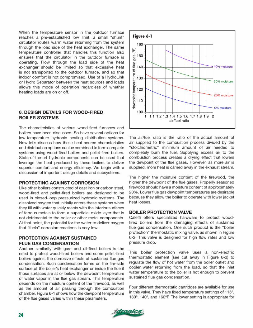
PROTECTION AGAINST SUSTAINED FLUE GAS CONDENSATIONAnother similarity with gas- and oil-fired boilers is the need to protect wood-fired boilers and some pellet-fired boilers against the corrosive effects of sustained flue gas condensation. Such condensation forms on the fire-side surface of the boiler’s heat exchanger or inside the flue if those surfaces are at or below the dewpoint temperature of water vapor in the flue gas stream. This temperature depends on the moisture content of the firewood, as well as the amount of air passing through the combustion chamber. Figure 6-1 shows how the dewpoint temperature of the flue gases varies within these parameters.
The air/fuel ratio is the ratio of the actual amount of air supplied to the combustion process divided by the “stoichiometric” minimum amount of air needed to completely burn the fuel. Supplying excess air to the combustion process creates a drying effect that lowers the dewpoint of the flue gases. However, as more air is supplied, more heat is carried away in the exhaust stream.
The higher the moisture content of the firewood, the higher the dewpoint of the flue gases. Properly seasoned firewood should have a moisture content of approximately 20%. Lower flue gas dewpoint temperatures are desirable because they allow the boiler to operate with lower jacket heat losses.
BOILER PROTECTION VALVECaleffi offers specialized hardware to protect wood-fired boilers from the damaging effects of sustained flue gas condensation. One such product is the “boiler protection” thermostatic mixing valve, as shown in Figure 6-2. This valve is designed for high flow rates and low pressure drop.
This boiler protection valve uses a non-electric thermostatic element (see cut away in Figure 6-3) to regulate the flow of hot water from the boiler outlet and cooler water returning from the load, so that the inlet water temperature to the boiler is hot enough to prevent sustained flue gas condensation.
Four different thermostatic cartridges are available for use in this valve. They have fixed temperature settings of 115º, 130º, 140º, and 160ºF. The lower setting is appropriate for
100
110
120
130
140
150
160
1 1.1 1.2 1.3 1.4 1.5 1.6 1.7 1.8 1.9 2
dew
poin
t tem
pera
ture
of fl
ue g
as (º
F)
air/fuel ratio
0% moisture
20% moisture
30% moisture
40% moisture
Figure 6-1

25
very dry firewood (10% to 15% moisture content) being burned with relatively high excess air. The upper setting would be appropriate for wood with higher moisture content (30% or more) being burned with low excess air. A cartridge calibrated for 140ºF is suggested for wood-fired boilers operating with seasoned wood.
When the boiler is first fired, the water leaving it is well below the temperature setting of the boiler protection valve. Under this condition, the cool water inlet port of the valve is fully closed and the hot water inlet is fully open, as shown in Figure 6-4a. All water leaving the boiler is routed directly back to the boiler’s inlet. No water is routed to the load. This allows the boiler temperature to rise as quickly as possible, and thus minimizes condensing mode operation.
As the water temperature leaving the boiler rises, the thermostatic element within the valve steadily closes the hot water inlet port and simultaneously opens the cool water inlet port. This allows some heated water to flow to the load, as shown in Figure 6-4b.
When the water temperature returning to the boiler reaches 18ºF or more above the temperature setting of the boiler protection valve, the valve’s hot water inlet port will be completely closed, and the “cool” port completely open. Under this condition, there is no flow in the bypass pipe, and all water leaving the boiler flows to the load, as shown in Figure 6-4c.
Hot inletfrom boiler
Cool
ret
urn
from
sys
tem
Mix
ed r
etur
nto
boi
ler
Valve body
Spring
Thermostaticsensor
Plug
Shutterwood-fired boiler
to load
from load
boiler!circulator
bypa
ss
boiler!protection!
valvewood-fired boiler
no flow to load
boiler!circulator
closed
no flow from load
bypa
ss
wood-fired boiler
to load
from load
boiler!circulator
no flow through!bypass
temperature = Tsetting +18ºF
closed
(a)
(b)
(c)
boiler!protection!
valve
boiler!protection!
valve
Figure 6-2
Figure 6-3
Figure 6-4 a,b,c

26
THERMOBLOC® MIXING DEVICEAnother Caleffi product combines the functionality of the boiler protection valve with the boiler circulator and a unique check valve that allows for thermosyphon flow between the boiler and load during a power outage. This “ThermoBloc” mixing device is shown in Figure 6-5. A cross section of the ThermoBloc is shown in Figure 6-6.
The ThermoBloc is installed as shown in Figure 6-7.
During normal operation (e.g., when electrical power is available), the ThermoBloc performs the same functions as the previously discussed boiler protection valve. However,
the ThermoBloc incorporates the boiler circulator, and thus speeds installation and reduces installation space and fittings. The ThermoBloc also includes thermometers that indicate the temperature of the hot and cool inlet streams, as well as the mixed temperature of the outlet stream.
A unique feature of the ThermoBloc is its ability to allow natural thermosyphon flow between the boiler and load during power outages. This operating mode helps prevent excessive heat buildup within the wood-fired boiler, which would eventually cause the pressure relief valve to open. During a power outage, a lightly loaded flapper valve within the ThermoBloc is pushed open by the slight pressure differential created by buoyancy
!ThermoBloc™!
boiler protection!device
wood-fired boiler
to load
from load
bypa
ss
Figure 6-5
Figure 6-7
Hot inletfrom boiler
Mix
ed re
turn
to b
oile
r
Coo
l ret
urn
from
sys
tem
Anti-condensation thermostatic sensor
Three-speed pump
Valve for natural circulation
Temperature pocket well
Temperature pocket well
Temperature pocket well
Figure 6-6
Tset
Tr
normally closed check valveopens due to bouyancy forcesto allow thermosyphon flow
circulator is off
Figure 6-8

27
effects of heated water in the boiler and cooler water in the storage tank, as shown in Figure 6-8. This flapper valve would normally be held shut by the pressure differential created by the circulator.
The ThermoBloc mixing device typically eliminates the need to include other “heat dumps” into residential and light commercial systems using wood-fired boilers. One common form of such a heat dump is shown in Figure 6-9. It uses a normally open zone valve in combination with several feet of fin-tube mounted above the boiler. During a power outage, the zone valve opens to allow thermosyphon flow through the fin-tube.
Although the configuration shown in Figure 6-9 provides both boiler protection and overheat protection, it is significantly more complicated and expensive than the alternative of using a ThermoBloc. It is also limited to situations where sufficient space is available to install the fin-tube above the boiler.
COMBINING A WOOD-FIRED BOILER WITH AN AUXILIARY BOILERThere are several ways to connect a wood-fired boiler with an auxiliary boiler. The usual intent is for the wood-fired boiler to handle the heating load until its output decreases due to fuel depletion. At that point, the conventional boiler turns on to supplement and eventually take over for the wood-fired boiler.
One seemingly simple method is to connect the boilers in series, as shown in Figure 6-11. Series piping requires system water to flow through both boilers, even if one of them is not operating. Air currents moving through and around the unfired boiler can absorb heat from this water and carry it up the chimney. Piping the boilers in series also increases the head loss against which the circulator must operate. Although the head loss of most wood-fired boilers as well as conventional boilers is small, this is not the case for some current-generation mod/con boilers. Series piping also precludes use of proper boiler protection. Because of these limitations, series piping is not recommended.
heat dump!(active during power failure)
!normally-open!
zone valve!(opens during!power failure)
wood-fired boiler
blower!off to load
from load
boiler!protection!
valve
wood-fired boiler
to load
from load
bypa
ss
heat dump!(active during power failure)
!normally-open!
zone valve!(opens during!power failure)
wood-fired boiler
blower!off to load
from load
=ThermoBloc™ boiler!
protection!valve
Figure 6-9
Figure 6-10

28
Parallel piping of multiple boilers is much preferred over series piping. Figure 6-12 shows a wood-fired boiler piped in parallel with an auxiliary boiler.
This arrangement places the auxiliary boiler before the buffer tank. It allows the tank to buffer heat input from
both the wood-fired boiler and the auxiliary boiler. It is especially appropriate when the auxiliary boiler has low thermal mass, or when the space-heating distribution system is extensively zoned. It is also desirable when the thermal mass of the buffer tank is being maintained at a temperature suitable for domestic water heating.
Figure 6-13 shows the auxiliary boiler piped after the buffer tank. This allows the buffer tank to cool to low temperatures at the same time the auxiliary boiler supplies heat to the load. It’s appropriate in systems where the auxiliary boiler’s heat output is well matched to the zoning of the distribution system so that short cycling will not occur. It’s also appropriate in systems where other low-temperature heat sources such as solar collectors or geothermal heat pumps may be used to add heat to the buffer tank when the wood-fired boiler is not operating. Keeping heat from the auxiliary boiler out of the buffer tank allows it to cool when the wood-fired boiler is not being used. Lower tank temperatures improve the heat gathering efficiency of both solar collectors and hydronic heat pumps.
auxiliary boilerwood-fired boiler
from load
ThermoCon tankwood-fired boiler
bypa
ss
to load
auxiliary!boiler
ThermoBloc™
Figure 6-11
Figure 6-12

29
ThermoCon tankwood-fired boiler
bypa
ss
to load
from load
auxiliary!boiler
ThermoBloc™
to / from!load
auxiliary boiler!(conventional)
hydraulic!separator
bypass
thermostatic!anti-condensation !
valve
bypa
ss
swing!check
pellet-fired boiler
generously sized headers!(for low head loss)
ThermoBloc™
Figure 6-13
Figure 6-14

30
Some pellet-fired boilers can maintain reasonable control over the rate of fuel combustion and may not require buffer tanks. In such a case, the pellet-fired boiler and an auxiliary boiler can be piped as shown in Figure 6-14.
The pellet-fired boiler is equipped with a ThermoBloc protection/circulation unit. The “conventional” auxiliary boiler (e.g., one not intended to operate with sustained flue gas condensation) is equipped with a thermostatic boiler protection valve. The boilers are piped in parallel to a common set of headers that connect to a hydraulic separator. The latter device isolates the boiler circulators from any circulators on the load side of the system. It also provides high-efficiency air separation and dirt separation for the system. A detailed discussion of hydraulic separators is given in idronics #1.
Each boiler is equipped with a check valve that prevents reverse flow of heated water through an inactive boiler. The check valve on the pellet-fired boiler should only be a “swing check” valve with very low forward opening resistance. This, in combination with the internal check mechanism in the ThermoBloc mixing device, allows for thermosyphon flow through the pellet-fired boiler during a power failure.
BUFFER TANKSOne of the challenges associated with wood-burning boilers is that the fire cannot be instantly turned on and off as it can with an oil- or gas-fired boiler. There will be many times when the heat output of the boiler exceeds the heating load of the building. There will also be times when the output from the wood-fired boiler cannot satisfy the load. This is especially true of wood gasification boilers that are designed to operate at high rates of combustion to achieve high combustion efficiency.
To achieve stable operation, thermal mass must be present in the system. Most outdoor wood-fired furnaces have large water volumes, and thus inherently provide sufficient thermal mass to stabilize system operation.
Wood-fired boilers typically do not have sufficient water volume to absorb all the heat generated by multiple hours of operation. The solution is to add water content to the system using a well-insulated buffer tank.
Buffer tanks can be either pressurized or unpressurized. Both approaches have their strengths and limitations.
UNPRESSURIZED BUFFER TANKS An unpressurized tank is essentially an insulated shell with a cover and vent tube. The latter ensures that no positive pressure develops at the top of the tank. An
example of an unpressurized buffer tank that can be site-assembled is shown in Figure 6-15.
Such tanks typically have a rectangular or cylindrical structural shell, sidewall, top and bottom insulation, and a flexible waterproof liner that can withstand years of contact with hot water.
Unpressurized tanks are not completely filled with water. A few inches of air space above the water accommodates the increased expansion volume as the water is heated. Piping connections are usually routed through the upper side wall or top of the tank so they remain above the water level, and thus are not subject to leakage.
For wood-fired boiler heating applications, these tanks typically have at least two copper coil heat exchangers suspended within the tank. An example of such a coil is shown in Figure 6-16.
Courtesy of American Solartechnics
Courtesy of American Solartechnics
Figure 6-15
Figure 6-16

31
Each coil is part of a separate closed and pressurized hydronic circuit: One for delivering heat from the boiler to the tank, the other for transferring heat from the tank to the distribution system. This approach allows the use of unpressurized tanks, but retains the advantages of closed/pressurized hydronic circuits. For example, a boiler constructed of cast iron or steel can be used since it is part of the closed-loop circuit. Since the tank water is isolated from both closed-loop circuits, the expansion tanks in those circuits do not have to accommodate the expansion of water within the buffer tank. A third suspended copper coil may be used for domestic water preheating, as shown in Figure 6-17.
One downside of using an open tank is that water evaporates from it over time. It is necessary to periodically check tank water level and add water
to keep all coils fully submerged. Also, because heat is typically added and extracted through heat exchangers, the temperature at which the tank can still supply sufficient heat to the load will be slightly higher than in systems where no heat exchanger is present. This is undesirable because it decreases the effective temperature range through which the tank can be cycled, and hence increases the necessary volume required to store a given amount of heat.
It’s also possible to use a single suspended heat exchanger coil for adding heat as well as removing heat from an unpressurized storage tank. This eliminates the cost of the second heat exchanger, and it improves the thermal efficiency of the system by reducing the temperature difference between the heat source and load. Figure 6-17a shows one way to do this.
wood-fired boiler
bypa
ss
vent
VENT
!air
space
liner
insulation
VENT
anti-scald!tempering!
valvehot
cold
(modulating)!tankless!
water heater
thermostatic!diverting!
valve
to / from!space
heating
check valve prevents
thermosyponing
ThermoBloc™
Figure 6-17

32
In this approach, a 4-way mixing valve body with standard internal vane has been combined with a 2-position motorized actuator. This combination allows the valve to reverse the flow direction through the suspended coil. The position of the actuator is controlled by either a line voltage or 24 VAC signal. Applying voltage to the actuator drives its shaft to the 90º position. Removing voltage allows an internal spring to return the actuator’s shaft to the 0º position. The movement of the actuator shaft produces a corresponding 90º rotation of the vane inside the 4-way valve.
Hot water passes downward through the coil when adding heat to the tank. This maximizes “counterflow” heat exchange between the coil and the stratified water in the
tank. Reversing the flow direction maintains counterflow heat exchange while heat is being removed from the tank.
This configuration also allows heat from the wood-fired boiler to pass to the HydroLink, and on to any active heating loads, without first warming the storage tank. This can be useful in situations where the building is recovering from a setback temperature while the storage tank is at a low temperature. In this mode, the 3-way motorized diverter valve bypasses flow around the suspended coil heat exchanger.
Heat can also be extracted from the storage tank and passed to the HydroLink without having to pass through the wood-fired boiler. This reduces heat loss in cases
VENT
wood-fired boiler
vent
HydroLinkspace heating loads
3-way diverter valves
modulating / condensing !auxiliary boiler
2-position!motorized!actuator
space heating loads
4-way mixing valve body
air space
suspended copper!heat exchanger!
(removing heat from tank)
alternate!position of!
valve's vane
suspended copper!heat exchanger!
(adding heat to tank)
ThermoBloc™
Figure 6-17a

33
where the storage tank is heated, but the wood-fired boiler is inactive. This is the mode shown in Figure 6-17a.
The piping configuration also allows easy integration of an auxiliary modulating/condensing boiler. A second 3-way motorized valve routes flow through the auxiliary boiler when necessary and bypasses flow around it at other times. With proper controls, it is even possible to absorb some heat from the wood-fired boiler and add supplemental heat from the auxiliary boiler.
A second suspended coil could be added to the storage tank for domestic water preheating. Another possibility would be to handle domestic water preheating using the subassembly shown in Figure 6-18 and described in the next paragraphs.
Figure 6-18 shows an alternative approach for combining closed-loop subsystems with a non-pressurized tank. In this system, externally mounted stainless steel brazed plate heat exchangers are used in lieu of suspended copper coils.
To maintain temperature stratification within the tank, cooler water needs to be extracted near the bottom of the tank and routed to the boiler-side heat exchanger. Likewise, cool water returning from the load-side heat exchangers needs to be diffused into water near the bottom of the tank. Ideally, the water would be introduced and extracted from the tank through horizontally oriented diffusers such as the tees shown in Figure 6-18.
The circulators that move fluid between the tank and external heat exchangers must be rated for “open-loop” applications, and as such will have wetted components made of stainless steel, bronze or polymers. It’s important to mount these circulators at least 3 or 4 feet below the water level in the storage tank. Doing so maintains a higher net positive suction head which helps avoid cavitation.
Purging valves have been shown in Figure 6-18 to allow water to be rapidly added to piping that enters the tank. High-velocity flow displaces air in the piping above the tank’s water level, driving it down and out through the open ends of the dip tubes. Once this air is displaced, water will remain in the piping above the water level provided that no air can enter this piping when it is under slight negative pressure. No air vents, valves or other piping components that could allow air entry should be placed in any piping above the tank’s water level.
The system in Figure 6-18 uses a third external heat exchanger to preheat domestic water. A flow switch turns on a small circulator whenever domestic hot water demand reaches approximately 0.5 gpm. Heated water from the buffer tank immediately flows through the tank side of the heat exchanger, transferring heat to the cold domestic water passing through the other side. In this system, a tankless electric water heater adds any additional heat needed to achieve the desired domestic hot water delivery temperature. An anti-scald-rated thermostatic tempering valve should be installed as shown to protect against the possibility of excessively hot
wood-fired boiler
bypa
ss
vent
!air
space to / from!space
heating
no air vents or other devices that could admit!air should be placed above the water level
all circulators handling tank water!should be stainless steel or bronze circulators
DHW!HX
flow switch
tankless electric!water heater
purge!valves
DHW
CW
no air vents or other devices that could admit!air should be placed above the water level
ThermoBloc™
Figure 6-18

34
domestic water being delivered during periods when the buffer tank is at elevated temperature.
PRESSURIZED BUFFER TANKSBecause they eliminate need for some heat exchangers, pressurized storage tanks allow for somewhat simpler design and slightly improved thermal performance. Because they become part of a closed hydronic system, tanks
constructed of carbon steel are acceptable. Likewise, other ferrous metal components such as cast iron circulators can also be used in these systems.
Pressure-rated tanks tend to cost more than unpressurized tanks on a dollar/gallon basis. They also require larger expansion tanks within the system.
ThermoCon !buffer tank
wood-fired boiler
bypa
ss to load
from load
!3-way!mixing!valve
outdoor temperature
sensor
supply temperature
sensor
ThermoBloc™
wood-fired boiler
bypa
ss
ThermoCon !buffer tank
ThermoCon !buffer tank
ThermoBloc™
Figure 6-19
Figure 6-20

35
Figure 6-19 shows the basic concept of an insulated/pressure-rated buffer tank placed between the wood-fired boiler and the load. In this configuration, the buffer tank also provides excellent hydraulic separation between the boiler circulator and any circulators on the load side of the system. A swing check valve is shown on the supply pipe from the boiler to the tank. Its purpose is to prevent reverse thermosyphoning between the buffer tank and boiler.
A 3-way motorized mixing valve is shown on the outlet side of the buffer tank. Its purpose is to reduce the supply water temperature from the potentially hot buffer tank to the temperature required by the space-heating distribution system. This valve can be operated so that it supplies a fixed temperature to the load, or it can be configured for outdoor reset control. Additional information on applying 3-way mixing valves is available in idronics #7.
Multiple buffer tanks, such as the Caleffi ThermoCon, can be combined to increase total storage capacity. In such applications, the tanks should be piped in a parallel reverse return configuration, as shown in Figure 6-20. This encourages approximately equal flow through all tanks.
Another option is to use a large single tank, as shown in Figure 6-21. In such cases, the tank’s piping should be such that temperature stratification is encouraged and preserved within the tank.
Be sure to check any relevant mechanical code requirements to see if tanks larger than 119 gallons need to be ASME certified. Caleffi can supply large buffer tanks meeting ASME requirements.
BUFFER TANK SIZINGThe size of the buffer tank used with wood-fired boilers depends on several factors. They include:
• How the boiler will be operated• How much wood can be added to the boiler’s firebox• The potential heat content of the firewood being used• The minimum operating temperature of the heating distribution system• The temperature and pressure ratings of the buffer tank
In some applications, the operator desires to fully charge the boiler with wood at a given time of day and have all heat produced by burning that wood sent to the buffer tank, regardless of any concurrent heating load. This method of operation is usually based on convenience and the time of day at which the operator is available to add wood. For example, the operator may want to fully charge the boiler in the morning before leaving for work and not add wood until the following evening. This is a common approach, and one that tends to increase the required size of the buffer tank.
The operating temperature of the heating distribution system will also affect the size of the tank. The lower the water temperature at which the distribution system can operate, the longer a given tank can supply the load before the system must shift to an auxiliary boiler. Low water temperature distribution systems that use heat emitters, such as radiant panels, panel radiators, extended surface fin-tube convectors or air handlers with large surface area coils, were discussed in section 4 and are recommended for systems with wood-fired heat sources.
pressurized thermal storage tankwood-fired boiler
bypa
ss
air vent
temperature sensor well
ThermoBloc™
Figure 6-21

36
The upper temperature limit of the buffer tank also plays a role in determining its size. Unpressurized storage tanks typically have temperature limits of 180ºF to perhaps 200ºF. Pressurized metal storage tanks could theoretically contain water at temperatures above the atmospheric boiling point (212ºF), but this is seldom done due to the safety considerations associated with storing “superheated” water.
The sizing procedure that follows is based on the buffer tank absorbing all the heat from a full charge of firewood and conservatively assumes no concurrent heating load. The volume of the buffer tank can be determined using Formula 6-1.
Formula 6-1
Where:v = required buffer tank volume (gallons)w = weight of firewood that can be loaded in the combustion chamber (lb)n = average efficiency of the combustion process (decimal percent)∆T = temperature rise of the tank based on absorbing all heat from the combustion (ºF)738 = a constant based on the heating fuel value associated with 20% moisture content firewood.
For example: Assume that the firebox of a wood-fired boiler, when fully loaded, can hold 100 pounds of seasoned firewood. The boiler’s average combustion efficiency is 80%. Determine the buffer tank volume needed assuming the tank will rise 60ºF as it absorbs heat from burning the full charge of wood.
Solution: Putting the data into Formula 6-1 yields:
This result shows that substantial volume may be required. It could be achieved with a single tank or by combining multiple tanks piped in parallel.
One way to reduce the required volume is to implement a control strategy that widens the temperature range over which the tank is used. With the upper temperature typically limited to 200ºF, the temperature range is usually widened by reducing the temperature at which the space-heating distribution system can operate.
7. EXAMPLES OF SYSTEMS USING WOOD-FIRED AND PELLET-FIRED BOILERS
This section presents several schematics for complete systems using either a wood-fired or pellet-fired boiler as their primary heat source. These systems are intended to cover the majority of applications in residential or light commercial buildings. However, when circumstances dictate, the versatility of modern hydronics, along with proper application of the design principals and subsystem discussed in earlier sections, should allow an efficient, stable and reliable alternative to be configured.
SYSTEM 1: Description: Space heating from a wood-fired boiler supplying a zoned distribution system. This is a basic system for space heating with an extensively zoned distribution system. The wood-fired boiler adds heats to the two ThermoCon buffer tanks piped in parallel reverse return. The boiler is protected against sustained flue gas condensation by a ThermoBloc mixing device.
The very low flow resistance of the buffer tanks provides hydraulic separation between the ThermoBloc circulator and the variable-speed pressure-regulated circulator used in the distribution system.
A 3-way motorized mixing valve operates based on outdoor reset control to provide stable delivery temperature to the heat emitters and to protect them from potential high-temperature water in the buffer tanks.
No auxiliary boiler is used.
SYSTEM 2: Description: Space heating and domestic water preheating from a wood-fired boiler with an auxiliary boiler and extensive zoning.
This system uses a low-mass “mod/con” (e.g., modulating/condensing) auxiliary boiler on the input side of the buffer tank, along with the wood-fired boiler. This arrangement buffers heat input from both the wood-fired boiler and the auxiliary boiler. Buffering heat input from the low-mass boiler prevents short cycling when heat is supplied to an extensively zoned distribution system. This configuration also allows the buffer tank to act as a hydraulic separator between the circulators on the heat input side of the buffer tank and those on the load side.

37
The buffer tank temperature is continually monitored by an outdoor reset controller. Upon a call for space heating from any of the zones, this controller determines if the water temperature in the tank can supply space heating based on the controller’s settings and the current
outdoor temperature. If so, the auxiliary boiler is not fired. If the temperature of the buffer tank is too low to supply space heating, the auxiliary boiler is fired to reheat the buffer tank to the temperature required by the space-heating distribution system.
wood-fired boiler
bypa
ss
!ThermoCon !buffer tank
!ThermoCon !buffer tank
variable speed!pressure regulated!
circulator
zone!valves
3-way!motorized!
mixing valve
extensively zoned distribution system
(P1)
!expansion!
tank
ThermoBloc™
DHW!HX
tankless electric!water heater
DHWCW
variable speed!pressure regulated!
circulator
zone!valves
3-way!motorized!
mixing valve
ThermoCon !buffer tank
wood-fired boiler
bypa
ss
outdoor!reset!
controllerextensively zoned
distribution system
auxiliary boiler!(mod/con)
(P1)
(P2)
(P3)small circulator with check valve
flow switch
ThermoBloc™
Figure 7-1
Figure 7-2
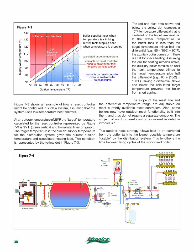
38
Figure 7-3 shows an example of how a reset controller might be configured in such a system, assuming that the system uses low-temperature heat emitters.
At an outdoor temperature of 25ºF, the “target” temperature calculated by the reset controller represented by Figure 7-3 is 95ºF (green vertical and horizontal lines on graph). The target temperature is the “ideal” supply temperature for the distribution system given the current outside temperature and associated heating load. This condition is represented by the yellow dot in Figure 7-3.
The red and blue dots above and below the yellow dot represent a 10ºF temperature differential that is centered on the target temperature. If the water temperature in the buffer tank is less than the target temperature minus half the differential (e.g., 95 - [10/2] = 90ºF), the auxiliary boiler comes on if there is a call for space heating. Assuming the call for heating remains active, the auxiliary boiler remains on until the tank temperature climbs to the target temperature plus half the differential (e.g., 95 + [10/2] = 100ºF). Having a differential above and below the calculated target temperature prevents the boiler from short cycling.
The slope of the reset line and the differential temperature range are adjustable on most currently available reset controllers. Also, some boilers now have outdoor reset functionality built into them, and thus do not require a separate controller. The subject of outdoor reset control is covered in detail in idronics #7.
This outdoor reset strategy allows heat to be extracted from the buffer tank to the lowest possible temperature “usable” by the distribution system. This lengthens the time between firing cycles of the wood-fired boiler.
Supp
ly w
ater
tem
pera
ture
(ºF)
Outdoor temperature (ºF)
70
90
110
130
70 60 50 40 30 20 10 0 -10 -20
contacts on reset controller!close to enable boiler!
as heat source
120
100
80
10ºF!differential!(shown) calculated target temperature
buffer tank supplies heat
boiler supplies
heat
contacts on reset controller!open to allow buffer tank!to serve as heat source
boiler supplies heat when!temperature is climbing. !Buffer tank supplies heat !when temperature is dropping
140
DHW!HX
tankless electric!water heater
(P3)small circulator with check valve
large thermal storage tankwood-fired boiler
bypa
ss
variable speed!pressure regulated!
circulator
3-way!motorized!
mixing valve
(P1)
(P2)
∆T controller
outdoor reset
controller
(T1)
(T2)
(P4)
flow switch
ThermoBloc™
Figure 7-3
Figure 7-4

39
Domestic water is heated instantaneously as it is needed. A flow switch detects whenever domestic water is required at a flow rate at or above 0.5 gpm. Under this condition, it powers on a small circulator that moves heated water from the buffer tank through the primary side of a stainless steel heat exchanger. Cold water is instantaneously preheated (or fully heated depending on the buffer tank temperature) as it passes through the other side of the heat exchanger. An electric tankless water heater provides any necessary boost in domestic hot water delivery temperature. An anti-scald-rated thermostatic mixing valve protects against high domestic water temperatures when the buffer tank is at an elevated temperature. For the fastest possible response, the piping between the buffer tank and heat exchanger should be short and fully insulated.
This configuration allows for domestic water preheating whenever the buffer tank is above the temperature of the entering cold domestic water. It is beneficial when the tank is “coasting” down to a lower temperature several hours after its last firing, or perhaps when fired only once every couple of days in warmer weather. It is also beneficial if other low-temperature heat sources such as solar thermal collectors or heat pumps are being used to add heat to the buffer tank when the wood-fired boiler is inactive. Arrangements for each of these scenarios are given in this section.
The 3-way motorized mixing valve is an essential part of the distribution system. It protects the low-temperature distribution system from what could be very high buffer tank temperatures when the wood-fired boiler is operating. The valve’s controller also operates based on outdoor reset logic to ensure stable indoor temperature and excellent comfort, regardless of which heat source is supplying the load.
SYSTEM 3: Description: Space heating and domestic water preheating from a wood-fired boiler supplying a large, pressurized storage tank with an auxiliary boiler and limited zoning.This system assumes that a large pressured buffer tank (500 gallons or larger) is used to absorb rapid heat generation from a wood gasification boiler. It uses a mod/con boiler for supplemental space heating. However, unlike the previous system, heat from the mod/con boiler is not stored in the buffer tank. Thus, to avoid short cycling, zoning should be limited based on the modulation ability of the auxiliary boiler.
Figure 7-5 in an electrical wiring diagram for controlling this system. A description of operation based on this wiring diagram is also given.
120 VAC
24 VAC
transformer 120/24 VAC
3-way!mixing!valve!
controller
R C
thermostat
M
thermostat
M
L1 N
P2R C
T Tboiler
outdoor!reset!
controller
relay
T1
T2
P1
relay
P3DHW flow switch
∆T controller!N.O. contacts closed!if (T1-T2)>=2 ºF
relay
(P4)
R C
Figure 7-5

40
DESCRIPTION OF OPERATION:Upon a call for space heating from either of the zone thermostats, the outdoor reset controller is turned on. If it determines the tank temperature is warm enough to supply the space heating load, a 24 VAC relay turns on circulator (P2). The 3-way mixing valve controller and variable-speed distribution circulator are also turned on upon a demand for heat from either zone.
If the tank temperature is too cool to supply the load, the normally open contact in the outdoor reset controller closes to power up a ∆T (differential temperature) controller. This controller measures the difference between hottest water at the top of the buffer tank and return temperature from the distribution system. If the top of the tank is at least 2ºF above the return temperature, the normally open contact in the ∆T controller closes to keep circulator (P2) operating. The boiler and circulator (P1) are also operating at this time. In this mode, there is simultaneous heat input from the auxiliary boiler and the buffer tank.
If the temperature difference between the buffer tank and the return side of the distribution system drops to less than 1ºF, there is very little heat being extracted from the tank. Under this condition, the ∆T controller turns off circulator (P2) to prevent heat generated by the auxiliary boiler from being added to the buffer tank. The auxiliary boiler and circulator (P1) remain on to supply the space heating load as required.
When the buffer tank temperature again rises to where the temperature differential between the top of the tank and the return side of the distribution system reaches 2ºF or more, circulator (P2) is turned back on to again extract available heat from the tank.
This control strategy is appropriate for larger storage tanks, where the ability to lower tank temperature a few additional degrees Fahrenheit represents perhaps 1 to 3 hours of heat input to the building.
Domestic water is heated instantaneously as needed. A flow switch detects a domestic water flow of 0.5 gpm or higher. Under this condition, it powers on a small circulator that moves heated water from the buffer tank through the primary side of a stainless steel brazed plate heat exchanger. Cold water is instantaneously preheated (or fully heated depending on tank temperature) as it passes through the other side of the heat exchanger. An electric tankless water heater provides any necessary boost in domestic hot water delivery temperature. An anti-scald-rated thermostatic mixing valve protects against high domestic water temperatures when the buffer tank is at an elevated temperature. For the fastest
possible response, the piping between the buffer tank and heat exchanger should be as short as possible and fully insulated.
This arrangement allows for domestic water preheating whenever the buffer tank is above the temperature of the entering cold domestic water. It is beneficial in situations where the tank is “coasting” down to a lower temperature many hours after it received heat from the wood-fired boiler. It is also beneficial if other low-temperature heat sources such as solar thermal collectors or heat pumps are being used to add heat to the buffer tank when the wood-fired boiler is inactive.
The 3-way motorized mixing valve is an essential part of the distribution system. It protects the low-temperature distribution system from what could be very high buffer tank temperatures when the wood-fired boiler is operating. The actuator controlling this valve operates based on outdoor reset logic. This ensures stable indoor temperature and excellent comfort, regardless of which heat source is currently supplying the load. Schematics presented later in this section show how such heat sources can be incorporated on the heat input side of the buffer tank.
SYSTEM 4: Description: Space heating and domestic water preheating from a wood-fired boiler supplying a pressurized buffer tank. Supplemental heat comes from a closed-loop solar thermal circuit.
This system is a modification of system 2. All details on the load side of the buffer tank are identical to those of system 2.
A closed-loop solar thermal system has been added to the heat input side of the buffer tank. The collector circuit operates with antifreeze and transfers heat to the buffer tank through a stainless steel brazed plate heat exchanger. The collector loop circulator and solar heat exchanger circulator are simultaneously operated by a differential temperature controller that continuously monitors the temperature difference between the collector array and the buffer tank. Whenever the collector temperature is a few degrees Fahrenheit above the tank temperature, these circulators are turned on to gather solar heat.
This system is particularly appropriate in situations where the wood-fired boiler will be infrequently fired during warmer/sunnier weather. During such times, very little, if any, space heating is required. Thus, much of the collected solar energy is available for domestic water heating. The latter is handled by the same “instantaneous” subsystem as discussed in the previous system.
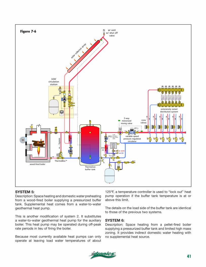
41
SYSTEM 5: Description: Space heating and domestic water preheating from a wood-fired boiler supplying a pressurized buffer tank. Supplemental heat comes from a water-to-water geothermal heat pump.
This is another modification of system 2. It substitutes a water-to-water geothermal heat pump for the auxiliary boiler. This heat pump may be operated during off-peak rate periods in lieu of firing the boiler.
Because most currently available heat pumps can only operate at leaving load water temperatures of about
125ºF, a temperature controller is used to “lock out” heat pump operation if the buffer tank temperature is at or above this limit.
The details on the load side of the buffer tank are identical to those of the previous two systems.
SYSTEM 6: Description: Space heating from a pellet-fired boiler supplying a pressurized buffer tank and limited high mass zoning. It provides indirect domestic water heating with no supplemental heat source.
DHW!HX
tankless electric!water heater
DHWCW
variable speed!pressure regulated!
circulator
zone!valves
3-way!motorized!
mixing valve
ThermoCon !buffer tank
wood-fired boiler
bypa
ss
extensively zoned distribution system
(P1)
(P2)small circulator with check valve
air vent!w/ shut off
valve
solar
collec
tor ar
ray
solar!circulation!
station
flow switch
ThermoBloc™
Figure 7-6

42
The heat output of a pellet-fired boiler can be better controlled compared to that of a wood-fired boiler designed to rapidly burn a full load of firewood. If the system has limited zoning, and especially if those zones use high thermal mass heat emitters such as heated floor slabs, it is not necessary to install a buffer tank.
The system in Figure 7-8 shows a pellet-fired boiler supplying radiant panels that operate as separate zones and at different supply water temperatures. Domestic water is heated by an indirect water heater operating as a third zone.
A hydraulic separator is used between the boiler and distribution system. This, in combination with generously sized load-side headers, provides good hydraulic
separation between all circulators in the system. It also provides the system with high- efficiency air separation and dirt separation.
The boiler is protected against sustained flue gas condensation by the ThermoBloc mixing device.
When any zone calls for heat, the pellet-fired boiler initiates combustion and its internal controls attempt to sustain a programmed supply water temperature on the outlet side of the hydraulic separator.
A 3-way motorized mixing valve operates based on outdoor reset control to maintain the required supply water temperature to the lower temperature radiant panel.
geothermal manifolds
water-to-water!heat pump(heating only)
Comp.
earth loop circuits
purging!valves
cond
ense
r
evap
orat
or
compressor
TXV
DHW!HX
tankless electric!water heater
DHWCW
variable speed!pressure regulated!
circulator
zone!valves
3-way!motorized!
mixing valve
ThermoCon !buffer tank
wood-fired boiler
bypa
ss
extensively zoned distribution system
(P1)
(P3)small circulator with check valve
flow switch
ThermoBloc™
Figure 7-7

43
The indirect water heater may be configured as a priority load based on the ability of the boiler’s controls.
SYSTEM 7: Description: Space heating and domestic water preheating from a pellet-fired boiler supplying a pressurized buffer tank. No supplemental heat source.
Because pellet-fired boilers can automatically start and stop based on heat demand, they are often the sole heat source in the system. The system shown in Figure 7-9 is based on this assumption. The pellet-fired boiler supplies heat to a relatively modest buffer tank that also serves as a hydraulic separator between the ThermoBloc and the circulators on the load side of the buffer tank.
The boiler’s internal controller monitors the temperature of the buffer tank and maintains it suitably high for domestic water heating.
Upon a demand for space heating from any of the zones, the appropriate zone circulator or mixing station is turned on. All space-heating zones are supplied through the HydroLink, which receives flow directly from the buffer tank.
Domestic water is heated instantaneously as needed. A flow switch detects a domestic water flow of 0.5 gpm or higher. Under this condition, it powers on a small circulator that moves
Hydro!Separator
indirect water heater
outdoor!temperature!
sensor
ThermoBloc™
DHW!HX
tankless electric!water heater
DHW
CW
ThermoCon !buffer tank
small circulator with check valve
bypa
ss
TRV
other!zones!
TRV
HydroLink
Monobloc
flow switch
Figure 7-8
Figure 7-9

44
heated water from the buffer tank through the primary side of a stainless steel brazed plate heat exchanger. Cold water is instantaneously preheated (or fully heated depending on tank temperature) as it passes through the other side of the heat exchanger. An electric tankless water heater provides any necessary boost in domestic hot water delivery temperature. An anti-scald-rated thermostatic mixing valve protects against high domestic water temperatures when the buffer tank is at an elevated temperature. For the fastest possible response, the piping between the buffer tank and heat exchanger should be short and fully insulated.
SYSTEM 8: Description: Space heating from a wood-fired boiler supplying a coil in a forced-air plenum.
This system is for buildings with a forced-air furnace. The wood-fired boiler delivers heat to the buffer tank(s). In this case, two Caleffi ThermoCon tanks are shown piped in parallel reverse return.
Upon a demand for heat from the first stage of a two-stage thermostat, the load circulator and 3-way motorized mixing valves are turned on. Hot water from the buffer tanks is delivered to a multi-pass coil mounted in the discharge plenum of the furnace. The furnace’s burner remains off at this point.
The air temperature leaving the plenum is monitored by the controller of the 3-way mixing valve. Depending on the ducting system, supply air temperatures of 100º to
wood-fired boiler
bypa
ss
!ThermoCon !buffer tank
!ThermoCon !buffer tank
water-to-air!heat exchanger !
coil
blower
3-way!motorized!
mixing valve
(P1)
T1
T2
optional differential!temperature controller
ThermoBloc™
120 VAC
24 VAC
transformer 120/24 VAC
2-stage!thermostat
3-way!mixing!valve!
controller
R C
sensors
L1 N
24 VAC!burner valve
P1R C
∆T controller!N.O. contacts !
closed!if (T1-T2)>=2 ºF
relay
furnace!blower
relay
1
2
relay
T1
T2
Figure 7-10
Figure 7-11

45
125ºF are typical. The air delivery temperature could also be based on outdoor reset control.
If the heat delivered by the plenum coil is insufficient to maintain room setpoint, the second stage contacts of the two-stage thermostat close. These contacts allow the burner in the furnace to operate. Circulator (P1) could be turned off at this point. Doing so prevents heat generated by the furnace from being absorbed by water flow through the coil. Circulator (P1) should have an internal check valve, or an external check valve should be provided to prevent any significant heat transfer from the coil back to the storage tanks.
If a large buffer tank volume is used, the control system could also be expanded to include differential temperature measurement across the coil when the furnace is operating. If the temperature drop across the coil is greater than a set minimum value (perhaps 2ºF), the coil is still contributing some heat to the air stream, and thus could remain active even when the furnace’s burner is operating. Once the temperature differential drops to perhaps 1ºF, very little heat is being contributed and circulator (P1) as well as
the mixing valve can be turned off. All heat is now being provided by the furnace. The control wiring schematic in Figure 7-11 shows the basic concept. However, wiring modifications may be needed depending on the internal wiring of the furnace blower and gas valve.
The schematic in Figure 7-10 doesn’t show provisions for domestic water heating. However, the instantaneous domestic water heating system shown in several previous system schematics could easily be incorporated into this system.
SUMMARY: The “rekindled” interest in wood as a heating fuel presents many opportunities for creative hydronic system design. The operating characteristics of wood-fired heat sources need to be respected when designing the balance of the system. Modern hydronic concepts such as buffer tanks, hydraulic separation, variable-speed distribution systems and low-temperature heat emitters can be combined to leverage the high-combustion efficiency attained by state-of-the-art wood- and pellet-fired boilers.

46
APPENDIX A: PIPING SYMBOL LEGEND
circulator
circulator w/!isolation flanges !
circulator w/!internal check valve!& isolation flanges !
gate valve
globe valves
ball valve
thermostatic!radiator valve
thermostatic!radiator valve
strainer
primary/secondary!fitting
cap
hose bib!drain valve
diverter tee
union
pressure gauge
diaphragm-type !expansion tank
3-way motorized mixing valve
4-way motorized mixing valve
swing check valve
spring loaded!check valve
purging valve
metered balancing valve
pressure relief valve
brazed !plate!heat !exchanger
Modulating / condensing boiler
conventional boiler
indirect water heater (with trim)
GENERIC COMPONENTS
pressure & temperature relief valve
CALEFFI COMPONENTS
solar collector array
DISCAL central!air separators !
backflow preventer
pressure reducing!valve
zone valve!(2 way)
zone valve!(3 way)
float -type!air vent
3-way !thermostatic mixing valve
flow-check valve
differential !pressure!bypass valve
VENT
Hydro Separator
Hydrolink!(3 configurations)
manifold station with balancing valves
pressure!relief valve
air & dirt!separator
DIRTCAL!dirt separator
high temperature!solar DISCAL !air separators !
high temperature!solar pressure!relief valve!
high temperature!solar air vent
high temperature!solar 3-way thermostatic!mixing valve
high temperature!solar !expansion!tank
isolar !differential temperature controller
flowcal!balancing!valve
high temperature!shut-off valve for!solar air vent
solar!circulation!station
mixing units!(2 configurations)
distribution!station
balancing!valve w/!flowmeter
wood-fired boiler
ThermoBloc™
boiler!protection!
valve

47
APPENDIX B: SIZING DIAPHRAGM-TYPE EXPANSION TANKS
All closed-loop hydronic systems require expansion tanks regardless of the heat source used. Closed-loop systems with wood-fired boilers and relatively large buffer tanks often require substantially larger expansion tanks due to the volume of water in the system. This appendix presents information for sizing the diaphragm-type expansion tanks commonly used in residential and light commercial systems.
A properly sized diaphragm-type expansion tank allows the pressure relief valve to reach a pressure about 5 psi lower than its rated opening pressure when the system reaches its maximum operating temperature. The 5 psi margin prevents the relief valve from leaking just below its rated opening pressure.
The first step in sizing a diaphragm-type expansion tank is to determine the proper air-side prepressurization of the tank using Formula B-1.
Formula B-1
Where:
Pa = air-side pressurization of the tank (psi)H = distance from inlet of expansion tank to top of system (ft)Dc = density of the fluid at its initial (cold) temperature (lb/ft3)
The proper air-side prepressurization is equal to the static fluid pressure at the inlet of the tank, plus an additional 5 psi allowance at the top of the system. The pressure on the air-side of the diaphragm should be adjusted to the calculated prepressurization value before fluid is added to the system. This is done by either adding or removing
air through the Schrader valve on the shell of the tank. A small air compressor or bicycle tire pump can be used when air is needed. An accurate 0 to 30 psi pressure gauge should be used to check this pressure as it is being adjusted. Many smaller diaphragm-type expansion tanks are shipped with a nominal air-side prepressurization of 12 psi. However, the air-side pressure should always be checked before installing the tank.
Proper air-side pressure adjustment ensures the diaphragm will be fully expanded against the shell of the tank when the system is filled with fluid, but before it is heated.
Failure to properly prepressurize the tank can result in the diaphragm being partially compressed by the fluid’s static pressure before any heating occurs. If this occurs, the full expansion volume of the tank will not available as the fluid heats up.
Figure B-1
Figure B-2

48
Once the air-side prepressurization is determined, Formula B-2 can be used to find the minimum required volume of the expansion tank:
Formula B-2
Where:
Vt = minimum required tank volume (gallons) Not “acceptance volume.”Vs = fluid volume in the system (gallons) Dc = density of the fluid at its initial (cold) temperature (lb/ft3)Dh = density of the fluid at the maximum operating temperature of the system (lb/ft3)Pa = air-side pressurization of the tank found using Equation B-1 (psi)PRV = rated pressure of the system’s pressure-relief valve (psi)
System volume can be estimated based on the total volume of the boiler, piping and other components in the system. Figure B-1 gives volumes for several common pipe types and sizes used in residential and light commercial systems.
The density of water over the temperature range of 50º to 250ºF can be read from Figure B-2.
Example: Determine the minimum-size diaphragm-type expansion tank for the system shown and described in Figure B-3.
Boiler volume = 20 gallonsPiping estimates: 50 feet of 1.5” copper 100 feet of 1” copper 2000 feet of 1/2” PEXMiscellaneous component volume = 3 gallonsMaximum buffer tank temperature = 200ºFMinimum system water temperature = 50ºFVertical distance from top of system to inlet of expansion tank = 12 feetPressure relief valve setting = 30 psi
Solution: Start by getting the density of water at both extremes:
D50ºF = 62.4 lb/ft3D200ºF = 60.15 lb/ft3
The total estimated system volume is found by totaling up the volume in piping and other components:
Vs = (50)(0.09505) + (100)(0.0454) + (2000)(0.009609) + 23 + 2(119) = 290 gallons
Formula B-1 can now be used to calculate the cold fill pressurization of the expansion tank:
Formula B-2 can now be used to calculate the expansion tank volume:
wood-fired boiler
!ThermoCon !buffer tank!(119 gallon)
!ThermoCon !buffer tank!
(119 gallon)
ThermoBloc™
Figure B-3

49
Discussion: This expansion tank volume is “conservatively” large because it assumes that all water in the system reaches the upper temperature of 200ºF simultaneously. This is not the case for piping downstream of the mixing valve (e.g., the radiant panel circuits). Thus, it is not necessary to add any additional safety factor to this volume.
The expansion tank volume is also considerably larger than required in most residential hydronic systems. This is a direct result of the large buffer tank volume (238 gallons) out of the total system volume (290 gallons). In this case, the expansion tank volume was approximately 10% of the total system volume. Given similar system operating conditions, it is reasonable to make a rough estimate of expansion tank volume using the 10% rule of thumb. However, variations in temperature, height or pressure-relief valve settings should always be evaluated using the above procedure.

Function
Technical specifications
Product rangeCode 280xxxA Boiler protection high-flow thermostatic mixing valve with 140ºF cartridge, threaded and sweat connections sizes 1”, 1-1/4”Code F29633 Themostatic sensor cartridge 115º FCode F29634 Themostatic sensor cartridge 130º FCode F29635 Themostatic sensor cartridge 140º FCode F29636 Themostatic sensor cartridge 160º F
series 280
ThermoMix™ boiler protection high-flow thermostatic mixing valve
CALEFFI
The ThermoMix™ boiler protection high-flow thermostatic mixing valve is used in hydronic heating systems with non-condensing boilers, including solid fuel, biomass, gas, LP or oil-fired. It can be installed with steel, cast iron and copper tube style boilers, automatically controlling the return water temperature, preventing condensation of the water vapor contained in the flue gas.
The 280 series ThermoMix valve mixes bypass flow from the boiler with return flow from the system, sending a fixed temperature flow to the boiler which protects against corrosion from condensation occurring when a minimum flue gas temperature is not otherwise maintained.
Changable thermostatic sensor cartridges modifies valve tempera-ture setting. The thermostatic sensor cartridge can easily be removed for maintenance or to change the valve set temperature, with out removing the valve body from the piping.
MaterialsBody and lower body plug: brass
Shutter: polysulfone
Spring: stainless steel
Seal: EPDM
Union seals: non-asbestos fiber
Thermostatic sensor: wax
PerformanceSuitable fluids: water, up to 50% glycol solutions
Max working pressure: 150 psi (10 bar)
Working temperature range: 40-212°F (5-100°C)
Thermostatic sensor cartridge: 140°F (60°C) standard
115°F (45°C), 130°F (55°C), 160°F (70°C) optional cartridges
Sensor cartridge accuracy: ±3.6°F (±2°C)
By-pass from boiler complete closing temperature: Tset +18°F (10°C)Cv: size 1”... 10Cv size 1-1/4“ ... 14Cv
Connections: - NPT male union 1” and 1¼”
- sweat union 1” and 1¼”
Code A B C D E F 280166A 1” NPT 3 1/2” 7” 6” 1 5/8” 4 3/8” 280966A 1” SWT 3 1/2” 7” 6” 1 5/8” 4 3/8” 280176A 1 1/4” NPT 3 13/16” 7 5/8” 6 3/16” 1 9/16” 4 3/8” 280976A 1 1/4” SWT 3 13/16” 7 5/8” 6 3/16” 1 9/16” 4 3/8”
Dimensions
140º F150 psi
50

Operating principle
The thermostatic sensor, completely immersed in the medium, controls the movement of a shutter that regulates the bypass flow from the boiler and toward the system. At boiler startup, the boiler protection thermostatic mixing valve recirculates the bypass flow from the boiler to bring the boiler up to temperature as quickly as possible (fig. 1). When the bypass flow from the boiler Tf exceeds the setting of the boiler protection mixing valve Tset, the valve’s return from the system port starts opening to produce the water mixing Tmix: in this phase the system loading begins (fig. 2).
When the mixed flow to the boiler temperature Tmix is greater than the set point of the boiler protection mixing valve by approximately 18°F (10°C), the bypass flow from the boiler port closes and water returns to the boiler at the same temperature as the return flow from the system.
Characteristic components
Bypassfrom boiler
Ret
urn
from
sys
tem
Mix
edto
boi
ler
Valve body
Spring
Thermostaticsensor
Plug
Shutter
System return
1
Tmix = Tset + 18°F BY-PASS CLOSINGby-pass closedsystem return open
Tf > Tmix = Tset +18°F, Tmix=Tr
3
Tf ≤ Tset SYSTEM START UPby-pass opensystem return closed
Tf ≤ Tset, Tmix=Tf
Construction details
SOLIDFUEL
BOILER
SOLIDFUEL
BOILER
f
f
Tf=Bypass flow from boiler Tmix=Mixed flow to boiler temperatureTset=Boiler protection valve set point temperature Tr=Return from system temperature
Tmix > Tset + 18°F SYSTEM LOADEDby-pass closedsystem return open
Tf > Tmix > Tset +18°F, Tmix=Tr
Tf > Tset START OF SYSTEM LOADINGby-pass opensystem return open
Tf > Tset, Tr < Tset, Tmix=Tset
2
4
f
fSOLIDFUEL
BOILER
SOLIDFUEL
BOILER
Flow curve
low
rate
The brass body prevents the formation of ferrous residues in the system, prolonging boiler operating life.The thermostatic sensor can be easily replaced for maintenance or set point change.
The boiler protection mixing valve body features temperature gage pocket wells on front and rear sides, allowing installation of a temperature gage (code F29571) for monitoring the working temperatures: bypass from boiler, return from system, and mixed to boiler.
Temp gage pocket wells (4)
1” 1-1/4”
F
.
.
.
.
.
.
.
4.5
7
4.3
3
1.5
0.7
p (psi)21
(l/mi
n)(g
pm)
2 4
10 20 200
8844229
Cv: size 1”... 10 size 1-1/4“ ... 14
51

Function
Technical specifications
Product range
Code 281xxxA Boiler protection unit, with 140º F cartridge, threaded and sweat connections sizes 1”, 1-1/4”
series 281
ThermoBloc™ Boiler protection recirculation and distribution unit
CALEFFI
MaterialsBody: brassShutter: PSUSpring: stainless steelFlapper check valve PPSSeal: EPDMThermostatic sensor: wax
PerformanceSuitable fluids: water, up to 50% glycol solutionsMax working pressure: 150 psi (10 bar)Working temperature range: 40-210°F (5-100°C)Termperature gage scale: 30-250°F (0-120°C)Thermostatic sensor cartridge: 140°F (60°C) standard 115°F (45°C), 130°F (55°C), 160°F (70°C) optional cartridgesSensor cartridge accuracy: ±3.6°F (±2°C) Bypass from boiler complete closing temperature: Tset +18°F (10°C)
Connections: - NPT male union 1” and 1-1/4” - sweat union 1” and 1-1/4”
PumpThree speed pump: Wilo Star S-16 U15Body: cast ironPower supply: 115 V - 60 HzMax. pressure: 150 psi (10 bar)Max. temperature: 230°F (110°C)Agency approval: cULus
InsulationMaterial: EPPMean thickness: 30 mmDensity: 45 kg/m3
Working temperature range: 40-210°F (5-100°C)Thermal conductivity: 0.037 W/(m.K) at 10°CReaction to fire (UL94): class HBF
Dimensions
The ThermoBloc™ boiler protection recirculation and distribution unit is used in hydronic heating systems with non-condensing boilers, including solid fuel, biomass, gas, LP or oil-fired. It can be installed with steel, cast iron and copper tube style boilers, automatically controlling the return water temperature, protecting against corrosion from condensation occurring when a minimum flue gas temperature is not otherwise maintained. The ThermoBloc unit is compact for easy installation, reducing required space and fittings. It combines the functionality of a boiler protection valve with a circulation pump and a unique flapper check valve allowing for thermosyphon flow between the boiler and distribution system during a power outage. The ThermoBloc includes three temperature gages and is encased in an insulation shell.
G F E D C B A edoC 281166A 1” NPT 8 3/4 5 ” 5/8 9 ”3 ” 7/8 1 ” 7/8” 8” 281966A 1” SWT 8 3/4 5 ” 5/8 9 ”3 ” 7/8 1 ” 7/8” 8” 281176A 1 1/4” NPT 8 3/4 5 ” 5/8 9 ”3 ” 7/8 1 ” 7/8” 8” 281976A 1 1/4” SWT 8 3/4 5 ” 5/8 9 ”3 ” 7/8 1 ” 7/8” 8”
281 Pump characteristcs
140º F150 psi210º F
52

Operating principle
The thermostatic sensor, completely immersed in the medium, controls the movement of a shutter that regulates the bypass flow from the boiler and toward the system. At boiler startup, the boiler protection recirculation and distribution unit recirculates the bypass flow from the boiler to bring the boiler up to temperature as quickly as possible (fig. 1). When the bypass flow from the boiler Tf exceeds the setting of the fixed thermostatic sensor Tset, the unit’s return from the system port starts opening to produce the water mixing Tmix: in this phase the system loading begins (fig. 2).
When the mixed flow to the boiler temperature Tmix is greater than the set point of the boiler protection recirculation and distribution unit by approximately 18°F (10°C), the bypass flow from the boiler port closes and water returns to the boiler at the same temperature as the return flow from the system (fig. 3).
When power is out and the circulation pump stops running, the flapper check valve, which is closed during normal operation, opens with a slight pressure differential resulting from the effects of heated water in the boiler and cooler water in the distribution syste, a natural thermosyphon flow. This prevents a excessive heat buildup which eventually would cause the pressure relief valve to open(fig. 4).
Characteristic components
The compact brass body casting houses the pump and all function-ing components, offering easy installation, either on the right or left side of the boiler. The temperature gages can be easily removed and re-inserted on the back side of the unit.
The brass body prevents the formation of ferrous residues in the system, prolonging boiler operating life.
The unit features a thermostatic sensor to control the temperature of water returning to the boiler to prevent condensation. The sensor can be easily replaced for maintenance or set point change.
The flapper check valve allows the natural thermosyphon circulation of the system heat transfer fluid when the pump stops running due to power failer. When the pump is running under normal conditions the thust of the flowing medium keeps the flapper closed, forcing flow past the thermostatic sensor. When the pump stops running and the fluid in the boiler is at high temperature, natural circulation begins, bypassing the thermo-static sensor, preventing overheating in the boiler.
By-pass from boiler
Mix
edto
boi
ler
Ret
urn
from
sys
tem
Tf
Tmix
Tset
Tr
Tf ≤ Tset, Tmix=Tf
by-pass open
system return closed
1Tf ≤ Tset BOILER START UP
Tf
Tmix
Tset
Tr
Tf > Tset START OF SYSTEM LOADINGTf > Tset, Tr < Tset, Tmix=Tset
2By-pass from boiler
Mix
edto
boi
ler
Ret
urn
from
sys
tem
by-pass open
system return open
By-pass from boiler
Mix
edto
boi
ler
Ret
urn
from
sys
temTrTmix
Tset
Tf
Tmix > Tset + 18°F SYSTEM LOADED
by-pass closed
system return open
Tf > Tmix > Tset +18°F, Tmix=Tr3
Normally closed check valve opens due to buoyancy forces to allow thermosyphon flow
PUMP OFF By-pass from boiler
Mix
edto
boi
ler
Ret
urn
from
sys
tem
Tf
Tmix
Tset
Tr
by-pass open
system return closed
4
By-passfrom boiler
Mix
ed
to b
oile
r
Ret
urn
from
sys
tem
Thermostatic sensor
Three-speed pump
Valve for natural circulation
Valve body
Temp. gauge pocket well (3)
ShuttleRitornoal generatore
Ritornoimpianto
4
3
54
53

Function
Technical specifications
Tank materials: porcelain coated steelTank insulation: 2" non-CFC foamTank external cover: powder-coated steel (20-24 ga.)Insulation thermal conductivity: R16Connections: top (3) 3/4" NPT female
Maximum working pressure: 150 psiTesting pressure: 300 psiMaximum tank temperature: 180°FRecommended maximum delivery hot water temperature: 120°F
ThermoCon™ buffer storage tanks
series NAS200
Product range
Code NAS20050 Storage tank 50 gallonCode NAS20080 Storage tank 80 gallonCode NAS20120 Storage tank 120 gallon
C
D
B
A
EF
Model A B C D E F
NAS20050 22” 48¼” 39½” 23½” 7¾”
NAS20080 24” 64” 53” 32” 11” 5”
NAS20120 28” 65” 53” 32” 11” 7”
4½”
A
¾” NPT
8”4”
2”NPT
2”NPT
2”NPTside (7) 2” NPT female
ThermoCon™ tanks are designed to be used for wood boilers, solar and geothermal storage, plus in heating systems with low-mass boilers, chilled water systems and low-mass radiation. ThermoCon tanks are used in systems operating below the design load condition, which is most of the time, or in systems having several low cooling or heating loads demands at different times. Boilers operat-ing at low loads will short cycle, resulting in reduced operating efficiency and shorter equipment life. When piped correctly, the ThermoCon will serve as both a thermal buffer and a hydraulic separator. The solar, boiler or chiller system will be hydraulically separated from the distribution system.
Dimensions
Meets and exceeds CSA C309 requirements
CALEFFI
Construction details The ThermoCon tanks are engineered with seven (7) 2” NPT connections. Two connections can be piped to the solar, boiler or chiller side and two connections can be piped to the distribution system. Two additional connection are 90 degree from another which allows for positioning tank into a corner with the piping at a right angle. The tank has one 2” NPT connection for connecting an external heat exchange in the middle of the tank.
54

Applications
geothermal manifolds
water-to-water !heat pump(heating only)
Comp.
earth loop circuits
purging !valves
cond
ense
r
evap
orat
or
compressor
TXV
DHW !HX
tankless electric !water heater
DHW
CW
variable speed !pressure regulated !
circulator
zone !valves
3-way !motorized !
mixing valve
ThermoCon !bu�er tank
wood-fired boiler
bypa
ss
extensively zoned distribution system
(P1)
(P3)small circulator with check valve
flow switch
DHW !HX
tankless electric !water heater
DHW
CW
variable speed !pressure regulated !
circulator
zone !valves
3-way !motorized !
mixing valve
ThermoCon !bu�er tank
wood-fired boiler
bypa
ss
extensively zoned distribution system
(P1)
(P2)small circulator with check valve
air vent !w/ shut o�
valve
solar c
ollecto
r arra
y
solar !circulation !
station
flow switch
55

COMPONENTS FOR BIOMASS SYSTEMS
• Designedandmanufacturedspecificallytobeusedinsystemswithwoodsolidfuelboilersintermsofefficiencyandsafety.
• ThermoBloc™combinesboilerprotectionvalvewithpumpintooneunittoprotectfluegasesfromcondensing.
• ThermoMix™boilerprotectionvalveisdesigntocontrolthereturntemperaturetoboilertoprotectfluegasesfromcondensing.
• ThermoCon™insulatedbufferingglasslinedstoragetankabsorbsalltheheatgeneratedbymultiplehoursofoperation.
• DISCAL®airseparatorautomaticallyremovesmicrobubblesfromsystemtoimproveefficiencyandsafety.
CALEFFI BIOMASS®: HUG NATURE, HUG CLEAN TECHNOLOGIES
www.caleffi.us