Enthalpy Energy Recovery Wheel Option - Daikin...
18
© 2006 McQuay International Enthalpy Energy Recovery Wheel Option McQuay Applied RoofPak™ Systems Heating and Cooling Units and Rooftop Air Handlers Type RPR/RFR/RDR 015C-075C, RAR 800C-802C and 47C Installation and Maintenance Manual IM 835 Group: Applied Systems Part Number: IM 835 Date: March 2006
Transcript of Enthalpy Energy Recovery Wheel Option - Daikin...

© 2006 McQuay International
Enthalpy Energy Recovery Wheel Option
McQuay Applied RoofPak™ SystemsHeating and Cooling Units and Rooftop Air Handlers
Type RPR/RFR/RDR 015C-075C, RAR 800C-802C and 47C
Installation and Maintenance Manual IM 835
Group: Applied Systems
Part Number: IM 835
Date: March 2006

Contents
McQuay and MicroTech are registered trademarks of McQuay International. DesignFlow, Hi-F, Protocol Selectability, RoofPak, SelectTools, SpeedTrol, SuperMod, UltraSeal, and VaneTrol
are trademarks of McQuay International.Microsoft is a registered trademark of Microsoft Corporation.
Windows is a trademark of Microsoft Corporation.Copyright © 2006 McQuay International. All rights reserved throughout the world.
Introduction . . . . . . . . . . . . . . . . . . . . . . . . . . . . . . . . . . . . . . . 1Arrangements . . . . . . . . . . . . . . . . . . . . . . . . . . . . . . . . . . . . . 2
System Description . . . . . . . . . . . . . . . . . . . . . . . . . . . . . . . 3Wheel Construction . . . . . . . . . . . . . . . . . . . . . . . . . . . . . . . . . 3Purge and Pressurization . . . . . . . . . . . . . . . . . . . . . . . . . . . . 4Drive Motor . . . . . . . . . . . . . . . . . . . . . . . . . . . . . . . . . . . . . . . 4Frost Protection Option . . . . . . . . . . . . . . . . . . . . . . . . . . . . . . 4Variable Speed Frequency Control . . . . . . . . . . . . . . . . . . . . . 4Alternate Frost Protection Measures . . . . . . . . . . . . . . . . . . . . 4
Startup and Operation . . . . . . . . . . . . . . . . . . . . . . . . . . . . . 5Prestartup Checks . . . . . . . . . . . . . . . . . . . . . . . . . . . . . . . . . . 5
Maintenance . . . . . . . . . . . . . . . . . . . . . . . . . . . . . . . . . . . . . . . 6Servicing Control Panel Components . . . . . . . . . . . . . . . . . . . 6Replacement Parts . . . . . . . . . . . . . . . . . . . . . . . . . . . . . . . . . 6Bearings . . . . . . . . . . . . . . . . . . . . . . . . . . . . . . . . . . . . . . . . . 6
Drive Motor . . . . . . . . . . . . . . . . . . . . . . . . . . . . . . . . . . . . . . . 6Drive Belts . . . . . . . . . . . . . . . . . . . . . . . . . . . . . . . . . . . . . . . . 6Seals . . . . . . . . . . . . . . . . . . . . . . . . . . . . . . . . . . . . . . . . . . . . 6Variable Frequency Controller . . . . . . . . . . . . . . . . . . . . . . . . . 6Wheel . . . . . . . . . . . . . . . . . . . . . . . . . . . . . . . . . . . . . . . . . . . . 6Enthalpy Wheel Removal . . . . . . . . . . . . . . . . . . . . . . . . . . . . . 6Troubleshooting . . . . . . . . . . . . . . . . . . . . . . . . . . . . . . . . . . . . 8
MicroTech II Sequence of Operation . . . . . . . . . . . . . . 9Enthalpy Wheel Control . . . . . . . . . . . . . . . . . . . . . . . . . . . . . . 9Exhaust Fan Control . . . . . . . . . . . . . . . . . . . . . . . . . . . . . . . 10Energy Recovery Bypass Damper Control . . . . . . . . . . . . . . 11
Typical Wiring Diagram . . . . . . . . . . . . . . . . . . . . . . . . . . . 12
Appendix . . . . . . . . . . . . . . . . . . . . . . . . . . . . . . . . . . . . . . . . . 13Power Twister Belt . . . . . . . . . . . . . . . . . . . . . . . . . . . . . . . . . 13

Introduction
Introduction
This manual provides installation and maintenance information about the enthalpy energy recovery wheel option (“enthalpy wheel”) featured on the following McQuay Applied RoofPak™ models:1 RPR/RFR/RDE 015C - 075C Packaged Heating and
Cooling Units2 RAR 800C - 802C and 47C Rooftop Air Handlers
General installation amd maintenance information on the rest of the unit is found in the following manuals:• IM 738 for Packaged Heating and Cooling Units• IM 487 for Rooftop Air Handlers• IM 696 for MicroTech™ II Controls• OM 137 for discharge air control for MicroTech II
Controls• OM 138 for space comfort for MicroTech II Controls
Figure 1: General Layout - (Approximate dimensions which vary with options)
Top
McQuay IM 835 1
Introduction
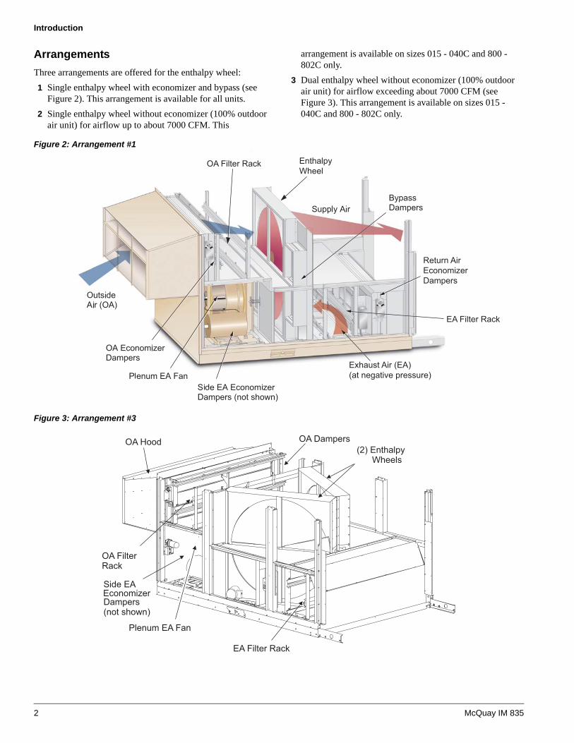
ArrangementsThree arrangements are offered for the enthalpy wheel:1 Single enthalpy wheel with economizer and bypass (see
Figure 2). This arrangement is available for all units.2 Single enthalpy wheel without economizer (100% outdoor
air unit) for airflow up to about 7000 CFM. This
arrangement is available on sizes 015 - 040C and 800 - 802C only.
3 Dual enthalpy wheel without economizer (100% outdoor air unit) for airflow exceeding about 7000 CFM (see Figure 3). This arrangement is available on sizes 015 - 040C and 800 - 802C only.
Figure 2: Arrangement #1
Figure 3: Arrangement #3
Return AirEconomizerDampers
EnthalpyWheel
OA Filter Rack
Exhaust Air (EA)(at negative pressure)
EA Filter Rack
OA Hood OA Dampers(2) Enthalpy
Wheels
EA Filter Rack
OA FilterRack
Side EA
Dampers(not shown)
Plenum EA Fan
Economizer
2 McQuay IM 835

System Description
System Description
When a unit is equipped with an optional enthalpy wheel (see Figure 2), energy recovery is provided by drawing outside air across half of the enthalpy wheel and drawing exhaust air across the other half. Latent heat and sensible heat are transferred from the hotter and moist exhaust air to the colder and dry outside air during winter conditions. Latent heat and sensible heat are transferred from the hotter and moist outside air to the cooler and dry exhaust air during summer conditions. Energy recovery control consists of starting and stopping an exhaust fan, modulating the speed of the exhaust fan, starting and stopping an enthalpy wheel, optionally controlling the speed of the enthalpy wheel and opening and closing a set of bypass dampers. The outdoor dampers are controlled in the normal manner. For more information, refer to OM 137 or OM 138. Also see “MicroTech II Sequence of Operation” on page 9.
Wheel ConstructionYour McQuay enthalpy wheel is delivered completely assembled and ready to run. The wheel is built to provide many years of trouble free service following proper installation and performance of the minimal maintenance requirements.
Definitions
The following are descriptions of various components related to the enthalpy wheel construction (see Figure 4):
Bearing, external - The wheel and bearing rotate on the shaft, no field lubrication is required.
Brush seal - The seal used for both the circumferential seal and the inner seal in the cassettes. They are constructed of nylon brush and configured to seal against the enthalpy wheel band in the case of the circumferential seal, and against the wheel face in the case of the inner seal. These seals are full contact seals, have an integral clip, and they are clipped to the cassette face panel cutout (concumferential) or to the (inner) post.
Cassette - The steel structure that houses the rotor. Cassettes are of punched sheet metal panelized construction.
Enthalpy wheel - A generic name for an energy conservation wheel. The term “enthalpy” refers to an air stream’s total energy (temperature and humidity level).
Exhaust air - The air stream that is exhausted to the outside. Exhaust air is building return air that has been run through the enthalpy wheel.
Heat wheel - Synonymous with an enthalpy wheel, energy conservation wheel, or total energy recovery wheel. Some heat wheels are sensible only wheels and should not be confused with McQuay total energy recovery wheels.
Hub - The center support of an enthalpy wheel.
Latent energy - Latent energy, in the context of enthalpy wheel discussions, is the work done by the wheel to transfer moisture from one air stream to another. Latent work is accompanied by humidity changes in the air streams.
Media - The chemical composite part of the enthalpy wheel which actually performs the latent and sensible exchange.
Outdoor air - The air stream that is brought in from the outside. Outdoor air becomes supply air after going through the enthalpy wheel.
Purge - A small segment of supply air defined by the gap between the inner seal on the outdoor air edge of the center post and the supply air edge of the center post. The purge angle is adjustable. The purge captures the small amount of supply air captive in the enthalpy wheel when the wheel moves from return to supply and routes it to return to minimize cross contamination.
Return air - The air stream that is returned from the building. Return air becomes exhaust air after going through the enthalpy wheel.
Rotor - The part of an enthalpy wheel that performs the energy exchange and consists of the wheel media, hub, spokes and band.
Sensible heat - Sensible energy, in the context of enthalpy wheel discussion, is the work done by the enthalpy wheel to transfer heat from one air stream to another. Sensible work is accompanied by temperature changes in the air stream.
Spoke - Flat metal member used to support the enthalpy wheel radially.
Supply air - The air stream that is supplied to the building space. Supply air is outdoor air that has been run through the enthalpy wheel.
Figure 4: Wheel Construction (Side-by-Side)
(1) Currently, only the Over-Under configuration is offered on McQuay rooftop systems and air handlers.
Enthalpy Wheel
Brush Seal
Cassette
Media
Hub
Side-by-SideConfigurationPurge Location
Spoke
MotorSheave
Drive Belt
Over-UnderConfigurationPurge Location1
1
McQuay IM 835 3

System Description
Purge and PressurizationPressurization is critical to minimize crossover from exhaust to supply and to allow the purge to operate.
Figure 5: Purge and Pressurization
Figure 6: Purge Detail
Drive MotorThe enthalpy wheel comes standard with a constant speed drive motor which is prewired to turn in the proper direction.
Frost Protection OptionDuring extremely cold winter conditions, exhaust air stream frost formation becomes a possibility. Frost formation will act to plug or reduce air flow but it will not hurt the enthalpy wheel itself.
To circumvent this frost possibility, McQuay offers a factory installed frost protection option (MicroTech II VFD system) that will control the speed of the enthalpy wheel for you (see “Variable Speed Frequency Control” below). The sequence of operation is detailed in “Variable Speed Enthalpy Wheel” on page 9.
Variable Speed Frequency ControlA variable frequency drive is included with the frost protection option and it controls the speed of the enthalpy wheel. The unit has also been programmed for the recommended range of wheel speed operation. Typical wheel speed is 45 RPM, but the programming can allow for wheel speeds above or below 45 RPM. Check all factory settings to make sure they are consistent with the application.
Enthalpy wheel speed will be controlled by exhaust temperature measurement.
Alternate Frost Protection MeasuresIf you choose not to have the frost protection option factory installed by McQuay, other frost protection measures must be considered.
Enthalpy wheel speed control functions to limit frost formation by reducing wheel performance to a level where the exhaust air temperature is kept above the dew point. Proper dew point control of exhaust air is determined by using psychrometrics (see Figure 8 on page 9):1 Locate the winter design return air condition and outdoor
air condition and connect the two points on a psychrometric chart.
2 Determine the dry bulb temperature at which this line intercepts the saturation curve.
3 Add 2°F and set dew point control at this point and vary enthalpy wheel speed downward to control at or above this point.
4 Audit performance of the enthalpy wheel during actual operation. If frost formation is never evident, it may be because design conditions are never reached. In such a case, it may be possible to gradually work dew point control down.
Any leakage must occurfrom outside to Exhaust Airdue to pressure gradient
Supply AirOutside Air atAtmospheric Pressure
Exhaust Air
Adjustable Purge(See Detail)
Plenum Exhaust Fandraws a negative pressure NOTE:
Maintain the pressure gradient toprevent cross contamination from theExhaust to Outside Supply Air
OUTSIDE AIR
EXHAUST AIR
Adjust purge in thisdirection to decreasecapacity and increasepurge
4 McQuay IM 835
Startup and Operation
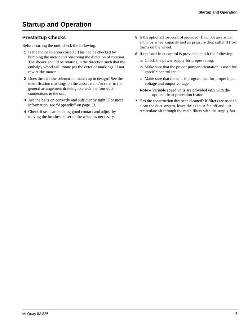
Startup and Operation
Prestartup ChecksBefore starting the unit, check the following:1 Is the motor rotation correct? This can be checked by
bumping the motor and observing the direction of rotation. The sheave should be rotating in the direction such that the enthalpy wheel will rotate per the exterior markings. If not, rewire the motor.
2 Does the air flow orientation match up to design? See the identification markings on the cassette and/or refer to the general arrangement drawing to check the four duct connections to the unit.
3 Are the belts on correctly and sufficiently tight? For more information, see “Appendix” on page 13.
4 Check if seals are making good contact and adjust by moving the brushes closer to the wheel as necessary.
5 Is the optional frost control provided? If not, be aware that enthalpy wheel capacity and air pressure drop suffer if frost forms on the wheel.
6 If optional frost control is provided, check the following:a Check the power supply for proper rating. b Make sure that the proper jumper orientation is used for
specific control input. c Make sure that the unit is programmed for proper input
voltage and output voltage.Note – Variable speed units are provided only with the
optional frost protection feature. 7 Has the construction dirt been cleaned? If filters are used to
clean the duct system, leave the exhaust fan off and just recirculate air through the main filters with the supply fan.
McQuay IM 835 5
Maintenance
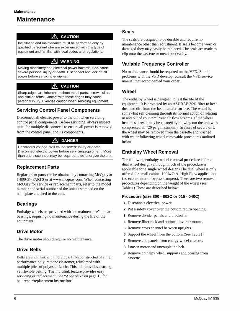
Maintenance
Servicing Control Panel ComponentsDisconnect all electric power to the unit when servicing control panel components. Before servicing, always inspect units for multiple disconnects to ensure all power is removed from the control panel and its components.
Replacement PartsReplacement parts can be obtained by contacting McQuay at 1-800-37-PARTS or at www.mcquay.com. When contacting McQuay for service or replacement parts, refer to the model number and serial number of the unit as stamped on the nameplate attached to the unit.
BearingsEnthalpy wheels are provided with "no maintenance" inboard bearings, requiring no maintenance during the life of the equipment.
Drive MotorThe drive motor should require no maintenance.
Drive BeltsBelts are multilink with individual links constructed of a high performance polyurethane elastomer, reinforced with multiple plies of polyester fabric. This belt provides a strong, yet flexible belting. The multilink feature provides easy servicing or replacement. See “Appendix” on page 13 for belt repair/replacement instructions.
SealsThe seals are designed to be durable and require no maintenance other than adjustment. If seals become worn or damaged they may easily be replaced. The seals are made to clip onto the cassette or metal post easily.
Variable Frequency ControllerNo maintenance should be required on the VFD. Should problems with the VFD develop, consult the VFD service manual that accompanied your order.
WheelThe enthalpy wheel is designed to last the life of the equipment. It is protected by an ASHRAE 30% filter to keep dust and dirt from the heat transfer surface. The wheel is somewhat self cleaning through its normal action of rotating in and out of countercurrent air flow streams. If the wheel becomes dirty, it may be cleaned by blowing out the unit with compressed air (20 psig maximum). In cases of severe dirt, the wheel may be removed from the cassette and washed with water following wheel removable procedures outlined below.
Enthalpy Wheel RemovalThe following enthalpy wheel removal procedure is for a dual wheel design (although much of the procedure is applicable for a single wheel design).The dual wheel is only offered for small cabinet 100% O.A. High Flow applications (no economizer or bypass dampers). There are two removal procedures depending on the weight of the wheel (see Table 1) These are described below:
Procedure (size 800 - 802C or 015 - 040C)1 Disconnect electrical power.2 Put a safety cover over the bottom return opening.3 Remove divider panels and blockoffs.4 Remove filter rack and optional inverter mount.5 Remove cross channel between uprights.6 Support the wheel from the bottom.(See Table1)7 Remove end panels from energy wheel cassette.8 Loosen motor and uncouple the belt.9 Remove enthalpy wheel supports and bearing from
cassette.
CAUTIONInstallation and maintenance must be performed only by qualified personnel who are experienced with this type of equipment and familiar with local codes and regulations.
WARNINGMoving machinery and electrical power hazards. Can cause severe personal injury or death. Disconnect and lock off all power before servicing equipment.
CAUTIONSharp edges are inherent to sheet metal parts, screws, clips, and similar items. Contact with these edges may cause personal injury. Exercise caution when servicing equipment.
DANGERHazardous voltage. Will cause severe injury or death.Disconnect electric power before servicing equipment. More than one disconnect may be required to de-energize the unit.
6 McQuay IM 835

Maintenance
Note – If the unit is equipped with an external flanged bearing, loosen the allen screws in the bearing housing that keeps the shaft affixed in the horizontal plane on both bearings, front and back. Remove the shaft clips at the face of the hub from both sides of the shaft. Unbolt one post completely and remove post with the bearing completely out. Remove the shaft. Roll the wheel carefully out.
10 Slide wheel out the front of the cassette.11 With the enthalpy wheel out, wash the media carefully with
water. Allow wheel to dry completely for several hours.
12 Reinstall the enthalpy wheel using the reverse procedure, Run the unit. It may take several hours for the desiccant to dry and for the wheel to perform normally.
Figure 7: Enthalpy Wheel Removal Components
Procedure (size 47C or 45 - 75C)
The enthalpy wheels in these larger units are too heavy and wheel removal, as described above for smaller units, is usually not practical. If a need arises to remove an enthalpy wheel from a size 47C or 45-75C, then there are two choices to consider, depending on the reason for removal:1 Disconnect electrical power.2 If the primary need is to clean the wheel:
a Normally the wheel can be cleaned with compressed air (20 psig maximum) while in place.
b If the wheel cannot be cleaned with compressed air, then water can be used. A drain pan is provided under the wheel for collecting the water.
c To clean the wheel with water, first remove the lower baffle located between the bypass damper and the wheel
blocking the drain pan. Clean the wheel with water while it is in place, but care must be taken that the water does not splash outside the drain pan.
d If the wheel cannot be sufficiently cleaned while in place, then the roof will have to be removed so a crane can be used to lift out and re-install the wheel. Follow steps 1-8, 10 and 11 (from the above procedure for size 800-802C or 015-040C) for loosening and reinstalling the wheel.
3 If the wheel must be replaced:a Cut the wheel into pieces that can be easily handled and
replace the wheel. b If using a crane and removing the unit’s roof is not
practical, then replace the existing wheel with a segmented wheel.
Table 1: Weight of the wheel less sheet metal cassette
Unit Size Weight
55" tall cabinet 300 Lbs.
73" tall cabinet, 6" wide wheel 800 Lbs.
73" tall cabinet, 12" wide wheel 1000 Lbs.
DividerPanels/Blockoffs (#2)
DividerPanels/Blockoffs (#2)
Filter Rack/Optional Inverter
Mount (#3)
CrossChannel (#4)
CrossChannel (#4)
Motor (#7)
CassetteEnd
Panel (#6)
CassetteEnd
Panel (#6)
Wheel (#9)
WheelSupports/
Bearing (#8)
McQuay IM 835 7

Maintenance
TroubleshootingThe following table may be used as a quick-reference for identifying common symptoms and possible causes related to the recovery wheel.
SYMPTOM CAUSE
Inadequate Wheel Performance
Check wheel rotation speed (see “Variable Speed Frequency Control” on page 4).
Check for wheel integrity and adjust seals or replace worn seals (see “Prestartup Checks” on page 5 and “Seals” on page 6).
Check entering air conditions and compare to design (see “Prestartup Checks” on page 5).
Check ducting for leakage and fix any leaks.
Check media for dirt and clean per cleaning instruc-tions (see“Wheel” on page 6 and “Enthalpy Wheel Removal” on page 6).
Improper Wheel Rotation
Check drive belts for engagement with sheave.
Check drive motor.
Check drive motor wiring for proper voltage.
Check VFD programming (provided with optional frost protection).
High Pressure Drop
Check air flow and compare to design.
Check filters and clean/replace as necessary.
Check media for plugging and clean per cleaning instructions (see “Enthalpy Wheel Removal” on page 6).
Noise
Check seals and adjust as necessary.
Check the bearings for source of noise.
Check the belt for slippage (see “Power Twister Belt” on page 13).
Wheel Will Not Operate
Check all electrical connections.
If MicroTech II controls are provided, make sure the building pressure is above setpoint such that the EAF turns on. The wheel does not operate unless the EAF is on (see “Exhaust Fan Control” on page 10).
8 McQuay IM 835
MicroTech II Sequence of Operation
MicroTech II Sequence of Operation
When a unit is equipped with an optional enthalpy wheel, energy recovery is provided by drawing outside air across half of the enthalpy wheel and drawing exhaust air across the other half. Latent and sensible heat is transferred from the hotter moist exhaust air to the colder dry outside air in winter. Latent and sensible heat is transferred from the hotter moist outside air to the cooler dry exhaust air in summer. Energy recovery control consists of starting and stopping an exhaust fan, modulating the speed of the exhaust fan, starting and stopping an enthalpy wheel, optionally controlling the speed of the enthalpy wheel and opening and closing a set of bypass dampers. The outdoor dampers are controlled in the normal manner. Refer to OM 137 or OM 138.The following sections describe the control of the enthalpy wheel, exhaust fan and bypass dampers.
Enthalpy Wheel ControlTable 2, below, lists the programmable parameters on the MicroTech II keypad that affect the operation of the enthalpy wheel.
When the Energy Recovery Control Flag is set to “Yes”, the enthalpy wheel is turned on whenever the unit exhaust fan is on and the current OA Damper Pos= parameter in the OA Damper menu indicates a value within 3% of the Effective Minimum Outdoor Damper Position Set Point. It is turned off when the exhaust fan is turned off or the OA Damper Pos= value is greater than the Effective Minimum Outdoor Damper Position Set Point by more than 3% (as when the unit is in the Econo operating state).
Constant Speed Enthalpy Wheel
When the unit is equipped with a constant speed enthalpy wheel, the wheel is driven to maximum speed whenever the enthalpy wheel is on.
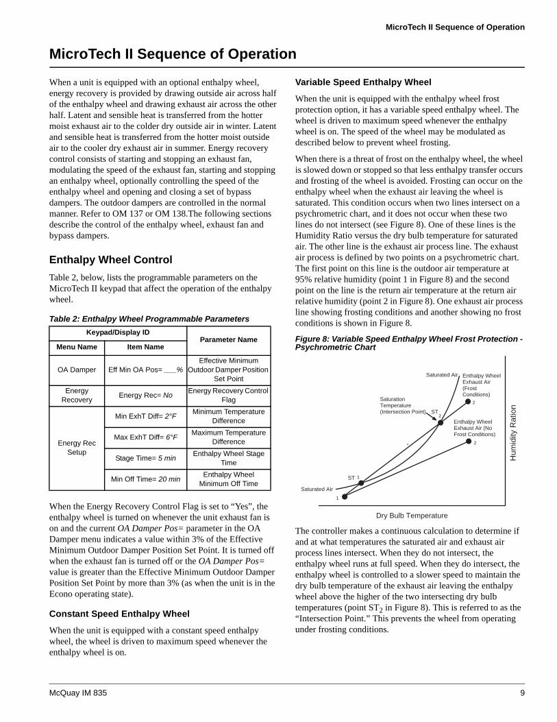
Variable Speed Enthalpy Wheel
When the unit is equipped with the enthalpy wheel frost protection option, it has a variable speed enthalpy wheel. The wheel is driven to maximum speed whenever the enthalpy wheel is on. The speed of the wheel may be modulated as described below to prevent wheel frosting.
When there is a threat of frost on the enthalpy wheel, the wheel is slowed down or stopped so that less enthalpy transfer occurs and frosting of the wheel is avoided. Frosting can occur on the enthalpy wheel when the exhaust air leaving the wheel is saturated. This condition occurs when two lines intersect on a psychrometric chart, and it does not occur when these two lines do not intersect (see Figure 8). One of these lines is the Humidity Ratio versus the dry bulb temperature for saturated air. The other line is the exhaust air process line. The exhaust air process is defined by two points on a psychrometric chart. The first point on this line is the outdoor air temperature at 95% relative humidity (point 1 in Figure 8) and the second point on the line is the return air temperature at the return air relative humidity (point 2 in Figure 8). One exhaust air process line showing frosting conditions and another showing no frost conditions is shown in Figure 8.
Figure 8: Variable Speed Enthalpy Wheel Frost Protection - Psychrometric Chart
The controller makes a continuous calculation to determine if and at what temperatures the saturated air and exhaust air process lines intersect. When they do not intersect, the enthalpy wheel runs at full speed. When they do intersect, the enthalpy wheel is controlled to a slower speed to maintain the dry bulb temperature of the exhaust air leaving the enthalpy wheel above the higher of the two intersecting dry bulb temperatures (point ST2 in Figure 8). This is referred to as the “Intersection Point.” This prevents the wheel from operating under frosting conditions.
Table 2: Enthalpy Wheel Programmable ParametersKeypad/Display ID
Parameter NameMenu Name Item Name
OA Damper Eff Min OA Pos= ___%Effective Minimum
Outdoor Damper Position Set Point
Energy Recovery Energy Rec= No Energy Recovery Control
Flag
Energy Rec Setup
Min ExhT Diff= 2°F Minimum Temperature Difference
Max ExhT Diff= 6°F Maximum Temperature Difference
Stage Time= 5 min Enthalpy Wheel Stage Time
Min Off Time= 20 min Enthalpy Wheel Minimum Off Time
Dry Bulb TemperatureH
umid
ity R
atio
n
1
1
2
2
2
Saturated Air Enthalpy WheelExhaust Air (FrostConditions)
ST
ST
Saturated Air
Enthalpy WheelExhaust Air (NoFrost Conditions)
SaturationTemperature(Intersection Point)
McQuay IM 835 9
MicroTech II Sequence of Operation
The following describes the details involved in the frost protection function that affect the speed and start/stop of the enthalpy wheel.• When the enthalpy wheel has been operating at maximum
speed for at least the Enthalpy Wheel Stage Time and the exhaust air temperature leaving the wheel (ER ExhT=) drops below the Intersection Point plus the Minimum Temperature Difference, the enthalpy wheel will be slowed to its minimum speed.
• If the enthalpy wheel has been operating at minimum speed for at least the Enthalpy Wheel Stage Time and the exhaust air temperature leaving the wheel (ER ExhT=) is still below the Intersection Point plus the Minimum Temperature Difference, the enthalpy wheel will be stopped.
• If the exhaust air temperature leaving the wheel (ER ExhT=) then rises above the Intersection Point plus the Maximum Temperature Difference and the enthalpy wheel has been off for longer than the Enthalpy Wheel Minimum Off Time, the wheel will be restarted and will run at its minimum speed.
• If the enthalpy wheel has been at minimum speed for longer than the Enthalpy Wheel Stage Time and the exhaust air temperature leaving the wheel (ER ExhT=) is still above the Intersection Point plus the Maximum Temperature Difference, the wheel will be increased to its maximum speed.
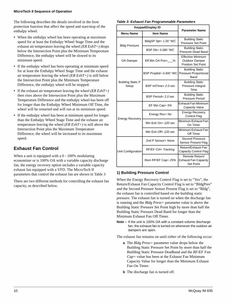
Exhaust Fan ControlWhen a unit is equipped with a 0 - 100% modulating economizer or is 100% OA with a variable capacity discharge fan, the energy recovery option includes a variable capacity exhaust fan equipped with a VFD. The MicroTech II parameters that control the exhaust fan are shown in Table 3
There are two different methods for controlling the exhaust fan capacity, as described below.
1) Building Pressure Control
When the Energy Recovery Control Flag is set to “Yes”, the Return/Exhaust Fan Capacity Control Flag is set to “BldgPres” and the Second Pressure Sensor Present Flag is set to “Bldg”, the exhaust fan is controlled based on the building static pressure. The exhaust fan is turned on when the discharge fan is running and the Bldg Press= parameter value is above the Building Static Pressure Set Point high by more than half the Building Static Pressure Dead Band for longer than the Minimum Exhaust Fan Off Timer.Note – If the unit is 100% OA with a constant volume discharge
fan, the exhaust fan is turned on whenever the outdoor air dampers are open.
The exhaust fan remains on until either of the following occur:a The Bldg Press= parameter value drops below the
Building Static Pressure Set Point by more than half the Building Static Pressure Deadband and the RF/EF Fan Cap= value has been at the Exhaust Fan Minimum Capacity Value for longer than the Minimum Exhaust Fan On Timer.
b The discharge fan is turned off.
Table 3: Exhaust Fan Programmable ParametersKeypad/Display ID
Parameter NameMenu Name Item Name
Bldg PressureBldgSP Spt= 1.00 “WC Building Static
Pressure Set Point
BSP Db= 0.080 “WC Building Static Pressure Dead Band
OA Damper Eff Min OA Pos=___%Effective Minimum Outdoor Damper Position Set Point
Building Static P Setup
BSP Propbd= 0.400 “WCBuilding Static
Pressure Proportional Band
BSP IntTime= 2.0 secBuilding Static
Pressure Integral Time
BSP Period= 2.0 sec Building Static Pressure Period
Energy Recovery
EF Min Cap= 5% Exhaust Fan Minimum Capacity Value
Energy Rec= No Energy Recovery Control Flag
Min Exh On= 120 sec Minimum Exhaust Fan On Timer
Min Exh Off= 120 sec Minimum Exhaust Fan Off Timer
Unit Configuration
2nd P Sensor= None Second Pressure Sensor Present Flag
RF/EF Ctrl= Tracking Return/Exhaust Fan Capacity Control Flag
Rem RF/EF Cap= 25%Remote Return/
Exhaust Fan Capacity Set Point
10 McQuay IM 835

MicroTech II Sequence of Operation
When the exhaust fan is on, its capacity is modulated to maintain the Bldg Press= parameter value at the Building Static Pressure Set Point using three PID control loop parameters. These are the Building Static Pressure Proportional Band, Building Static Pressure Integral Time and Building Static Pressure Period. Although these parameters can be adjusted, for most applications, the factory default values for these parameters provide the best control. For detailed information regarding tuning PID control loop parameters, refer to “MicroTech II DDC Features” in OM 137.
2) Direct Position Control
When the Energy Recovery Control Flag is set to “Yes” and the Return/Exhaust Fan Capacity Control Flag is set to “Position”, the exhaust fan is controlled based on Remote Return/Exhaust Fan Capacity Set Point. This set point can be adjusted via a network signal. The exhaust fan is turned on when the discharge fan is running and the exhaust fan capacity is commanded above the Exhaust Fan Minimum Capacity Value for longer than the Minimum Exhaust Fan Off Timer.
The exhaust fan remains on until either of the following occur:a The Remote Return/Exhaust Fan Capacity Set Point is
commanded to the Exhaust Fan Minimum Capacity Value for longer than the Minimum Exhaust Fan On Timer.
b The discharge fan is turned off. Note – If the unit is 100% OA with a constant volume
discharge fan, the exhaust fan is turned on whenever the outdoor air dampers are open.
Energy Recovery Bypass Damper ControlWhen a unit is equipped with a 0-100% modulating economizer, the energy recovery option includes a set of bypass dampers (see Figure 9) that allow air to bypass the energy recovery wheel when the wheel is not operating. The dampers are driven closed for 2 minutes whenever the energy recovery wheel is turned on, forcing the entering and leaving air to go through the wheel. When the outdoor air dampers are driven more than 3% above the effective Minimum Outdoor Damper Position Set Point (as when the unit enters the Economizer operating state the wheel is shut off and the bypass dampers are driven open for 2 minutes allowing the entering and leaving air to bypass the wheel.
Figure 9: Bypass Damper Control
Table 4: Programmable ParametersKeypad/Display ID
Parameter NameMenu Name Item Name
OA Damper Eff MinOA Pos= ___%Effective Minimum Outdoor Damper Position Set Point
� � � � � � �� �
� � � � � �
� � � � � �� �
� � � � � � � � � �� � � � � � � �
� � � � � � �� � � � � � � �
� � � � � � � �
� � � � � �� � � � � � � � � � �
� � � � � � � � � � � � � � � � � � � � � � � �� � � � � � � � �
� � � � � � � � � � �� � � � � � � � � � � � � � � � � �
� � � � � � � � � �
McQuay IM 835 11

Typical Wiring Diagram
Typical Wiring Diagram
The following is a common wiring diagram for the enthalpy wheel.
� � � � � � !" # � � �$ � �
� � � % �" # � � �& � � � �
' � � � (
' ( � � (
' ) � � (
� ( � ' �
� ( � ' (
� ( � ' )
' �' �
' (' (
' )' )
* �
* (
* )
+ , ! ) � �
+ , ! - � �
+ , ! . � �
+ , ! � �
/ 0 � �
+ , ! ) � �
+ , ! - � �
+ , ! . � �
1 �
$ �
" �
/ 0 �
1 (
$ (
" (
* �
* (
* )
& * � , ) -
* � 2 � � � . $ � 3 � 4 5 * ( 2 � ( - $ � 3 ( 4 -
6 � �� � 5
& � �
& � �
, � ( � ! .
� !
. . 0 �( ! 7 � � � ' � 6 � �
0 �
( ! 7 � � � � 0 �
8 � � �
8 � � �
( - $ � 6 � �
( - $ � 6 � �
, � ( �
, � (
, � (
+ , � ( � 7
+ , � ) �
+ , � - � � !
+ , � ) � !
+ , � ( � 7
+ , � - � � !
-
(
)
�
�
-
(
)
+ , � ( � 5
+ , � ( � 5
� � "
� � "
( - $
( - $
� "
� "
� � &
� � &
� � � � & � � �
� � � � & � � �
9 0 � � * )
9 0 � � * -
� ' � �) ! ) �
* ) 2 � � & * ( 2 � � & 3 ( 4 - 7 * � 2 0 3 � 4 5
( - $ ( - �
: � !
� ; 7
� ; ,
� ; � !
� ; 5
� ; � �
� ; � (
0 ( 90 (
� �
( ! , �( � ! �( � � �
" + *� ' <� � 0
0 ( 9 3 ( 4 � �0 ( 9 3 ( 4 � (� � 3 ( 4 � (
" + *
� ' <
� � 0
, ( - �
, ( . �
+ , ( - � �
+ , ( . � (
� � 0 -
9 � �� ' ( -
�
(
-
0 � � � � � � � � � � � � � � �� � � � � � � � � � � � � � �
� " ; * + � � � " � 6 � � ; 0 /� * 1 � 0 � � ' � 6 � �
� " ; * + � � " � 6 � � ; 0 /� * 1 � 0 � � � 0 �
� � � � � � � �
9 0 � *
� = + 1 6 * � ; � � 6 0 6 � �' $ ; 0 / � " + ' �
: 5
0 (� 1 6
; �
� � &
6 $ � �
; (
� � &
;
; )
� � &
6 $ � �
: 1 & � � 6
0 � '
0 � '
� ! �
� ! (� ; 6 � '
� ; 6 � '
� : 1 & � � �' � � * �
: 1 6 * � 1 0 � �� � & & 4 � � � � �
� � � % �� � � � > � � �� � � �
� � �
; 0 � 1 * 6� ; ? � ; 0 � @ ; ? 0 ' � /
, ) ! �
, ) � �
" + *
� ' <� � 0
+ , ) ! � �
+ , ) � � (
� � 0 -
9 � �� ' ( )
�
(
-
9 0 � *
� ' $ ; 0 / � ; � � 6 0 6 � �� 1 * � � � � � ; � �' $ ; 0 / � " + ' �
' �
� 6 � � � 1 � � 0 � � 6 ' � " � � � " 0� 1 * � 1 * � � ' @ 6 � � � � � * + � $ � � �
� 6 � � � 1 � � 0 � � 6 ' � " �� � " 0 � � 1 * � 1 * � � ' @ 6 �� � � � * + � $ � � �
� � @ � 6 6 � � & � � �
� � @ � 6 6 � � & � � 6 � � � 0� 1 � ; 0 / � � � 0 � & ; A � �� � � * ; � 0 �
9 0 � � * � (
� ' � 6
� � 0
� � "
� "
� � &� ' ( (
� ' ( (
� ' ( (
+ , ) , � )
)
-
(
+ , ) , � -
+ , - � � (
, - ! �
, - � �
, ) - �� ' � (
�
+ , ) - � � + , ) - � (� ' � (
(, ! )
* ) 2 � � &
� 1 = ; ' ; � @ � � � 0 * � * � � 0 � * + " + ' � & � * � � � � � 0 6 � " + 0* + � & � * � � � ; 6 � � � � �
9 0 �& * � � � !
7 5
�
(
)
� � �
� � & 0 �
� � � & � � � B � �
� � (
� � & 0 � -.
75
� � )
� � & 0 �
� � -
� � & 0 �� � .
� � & 0 � � �
� � & 0 �� �
� � & 0 � � � 7
� � & 0 �
� � 5
� � & 0 �
� � ,
� � & 0 �
, � !
� �
� ( � )
� -
� .� .�
� 7 � 5
� , ( !
)!)
* ) 2 ( - $
� � � & � � � B ( �
, - - �
, - �
)!)�
� . 5 2 . ,
+ � � 0
+ � 1 �
+ � �
, �
$ � � � � � � � * # � � � � � % �� � � � > � � � � " # � � �
5 � !� �� )
� ( ,� -
, ! )
9 0 � � � !
� ' � ( � ' � ( � ' � ( � ' � (
+,.7�7
+,.7�5
+,.7��(
+,.7�,
� (5 , 7
, . 5 �
, . 5
, . , � !
, ) -
� � 0 6 � 0 � � � � � � 6* + � $ � � � * � � ' � " �6 � � � " + 0 � * + �" + ' � & � * � �
; 6 � � � � � * + � � 1 / + � � !� � � � � � , ) - �
,.5
+ ( 1 � + ( $ + ( � 0
� . 5 2 . ,
, - -
, .
12 McQuay IM 835

Appendix
Appendix
Power Twister BeltThe following Power Twist® Belt information offers instruction on how to measure, disassemble, assemble, and install the belt.
Belt Length Measurement
The following steps give the correct installed belt length and will provide optimum belt tension when running. 1 Pull belt tight around sheaves to check hand tight length,
overlapping the last two tabs with two holes in matching links as shown below.
2 Count the number of links and remove one link for every 24 links.
Note – Every tenth link is designated with an arrow.
Belt Disassembly1 Hold belt upside down. Bend back as far as possible; hold
with one hand. Twist one tab 90° parallel with slot.
2 Pull end of link over tab.
3 Rotate belt end with tab 90°.
4 Pull belt end through two links.
Belt Assembly1 Hold belt with tabs pointing outward.
2 Place end tab through two links at once.
3 Flex belt further and insert second tab through end link by twisting tab with thumb.
McQuay IM 835 13

Appendix
4 Ensure tab returns to position across belt. Reverse belt so tabs run inside.
Belt Installation1 Disconnect electrical power.2 Turn belt with tabs to the inside before installing.3 Determine direction of the drive rotation.4 Align belt directional arrow with drive rotation. 5 Fit belt in nearest groove of smaller sheave.6 Roll belt onto larger sheave, turning the drive slowly. Belt
may seem very tight, this is okay; DO NOT JOG MOTOR.
7 Roll belt onto larger sheave, turning the drive slowly. Belt may seem very tight, this is okay; DO NOT JOG MOTOR.
8 Check to see that all tabs are still in their correct position and are not twisted out of alignment.
Alternative Belt Installation Method1 Set motor to mid position of adjustment range and mark
base clearly.
2 Determine required belt length (see “Belt Length Measurement” on page 13).
3 Push motor forward to minimum center distance.4 Install belts as in (see “Belt Installation”).5 Pull motor back to previously marked mid position.
Retensioning
Like all high performance V-belts, PowerTwist Plus V-Belts require the maintenance of correct drive tension to operate efficiently. Experience indicates that drive tension should be checked after the first 24 hours running at full load. A retension may be necessary depending on the severity of the drive. Any initial belt stretch is then taken up. Subsequently, belt tension should be checked periodically and adjusted when necessary.
14 McQuay IM 835

13600 Industrial Park Boulevard, Minneapolis, MN 55441 USA (612) 553-5330
McQuay Training and Development
Now that you have made an investment in modern, efficient McQuay equipment, its care should be a high priority. For training information on all McQuay HVAC products, please visit us at www.mcquay.com and click on training, or call 540-248-9646 and ask for the Training Department.
WarrantyAll McQuay equipment is sold pursuant to its standard terms and conditions of sale, including Limited Product Warranty. Consult your local McQuay Representative for warranty details. Refer to Form 933-43285Y. To find your local McQuay Representative, go to www.mcquay.com.
This document contains the most current product information as of this printing. For the most up-to-date product information, please go to www.mcquay.com.