EARTHQUAKE VULNERABILITY ASSESSMENT OF … VULNERABILITY ASSESSMENT OF RC FRAMED BUILDINGS Submitted...
68
EARTHQUAKE VULNERABILITY ASSESSMENT OF RC FRAMED BUILDINGS Submitted In the partial fulfillment for the Award of degree of Masters of Technology in Structural Engineering Submitted By Anand Paul (2011 PST 5111) Supervisors DEPARTMENT OF CIVIL ENGINEERING MALAVIYA NATIONAL INSTITUTE OF TECHNOLOGY JAIPUR June 2013 Dr. S. D. BHARTI Dr. M.K. SHRIMALI Downloaded from CivilDigital.com
Transcript of EARTHQUAKE VULNERABILITY ASSESSMENT OF … VULNERABILITY ASSESSMENT OF RC FRAMED BUILDINGS Submitted...

EARTHQUAKE VULNERABILITY ASSESSMENT OF RC
FRAMED BUILDINGS
Submitted In the partial fulfillment for the Award of degree of
Masters of Technology in Structural Engineering
Submitted By
Anand Paul (2011 PST 5111)
Supervisors
DEPARTMENT OF CIVIL ENGINEERING
MALAVIYA NATIONAL INSTITUTE OF TECHNOLOGY JAIPUR
June 2013
Dr. S. D. BHARTI Dr. M.K. SHRIMALI
Downloaded from CivilDigital.com

ii
EARTHQUAKE VULNERABILITY ASSESSMENT OF RC
FRAMED BUILDINGS
Submitted In the partial fulfillment for the Award of degree of
Masters of Technology in Structural Engineering
Submitted By
Anand Paul (2011 PST 5111)
Supervisors
DEPARTMENT OF CIVIL ENGINEERING
MALAVIYA NATIONAL INSTITUTE OF TECHNOLOGY JAIPUR
June 2013
Dr. S. D. BHARTI Dr. M.K. SHRIMALI
Downloaded from CivilDigital.com

iii
CERTIFICATE
This is to certify that the dissertation work entitled “Earthquake Vulnerability Assessment of
RC Framed Buildings” which is being submitted by Mr. Anand Paul in partial fulfillment for
the award of the degree of Master of Technology in Structural Engineering, MNIT, JAIPUR is a
bonafied work done by him under our guidance and supervision.
Date:
Place:
(Dr. M.K. Shrimali)
Department of Civil Engineering
MNIT Jaipur
(Dr. S. D. Bharti)
Department of Civil Engineering
MNIT Jaipur
Downloaded from CivilDigital.com

iv
ACKNOWLEDGEMENT
I express my deep gratitude to my guides Dr. M.K. Shrimali and Dr. S.D. Bharti for their
valuable guidance and instructions during the course of this dissertation. This dissertation report
would not have been possible without solemn guidance & co-operation of people who are involved
directly or indirectly.
(Anand Paul)
Downloaded from CivilDigital.com

v
ABSTRACT
Past earthquakes in India and round the globe have shown that soft ground story in the building
causes a serious risk to their integrity and stability. Substantial damages or collapses of numerous
buildings with soft ground story irregularity in recent earthquakes compelled an intense research
effort, employing linear and nonlinear analysis methods to assess the performance and capacity of
such buildings under seismic actions.
Objective of this study is to demarcate the nonlinear behavior of the structures by nonlinear static
pushover to evaluate the limits and efficacy of current design philosophies of analyzing and
designing buildings and also to validate the adaptability and adoptability of open ground story
structures in Indian seismic scenario. A set of three dimensional analytical models with various
structural arrangements, viz. bare frame and infilled frame models are investigated with nonlinear
static pushover, considering various site parameters. The investigation methodology consists of
(a) Creating analytical finite element models representing the building in India
(b) Determining the nonlinear member parameters
(c) Performing the nonlinear pushover analyses on these models
(d) Assessing codal provisions by evaluating the results obtained.
Using these analysis results, the open ground story behavior is scrutinized for studying the scope
and significances of this irregularity in detail. In addition, Indian code is evaluated considering the
soft ground story irregularity and the provisions suggested by code are ascertained.
Keywords: Open ground story, Pushover Analysis, Equivalent Diagonal Strut Model
Downloaded from CivilDigital.com

vi
Contents CHAPTER 1. .......................................................................................................................................... 1
1.1 Introduction ............................................................................................................................. 1
1.2 Objectives and Scope ............................................................................................................... 2
1.3 Thesis Organization ................................................................................................................. 3
CHAPTER 2. .......................................................................................................................................... 4
REVIEW OF LITERATURE .................................................................................................................. 4
2.1 Soft Storey ............................................................................................................................... 4
2.2 Masonry Infill in RC Frames .................................................................................................... 6
2.2.1 Infill Panels with Openings ............................................................................................. 11
2.3 Nonlinear Static Analysis Methods ......................................................................................... 12
CHAPTER 3. ........................................................................................................................................ 18
SOFT STORY IRREGULARITY.......................................................................................................... 18
3.1 General .................................................................................................................................. 18
3.2 Soft Story Behavior ................................................................................................................ 18
3.3 Indian Earthquake Code ......................................................................................................... 20
CHAPTER 4. ........................................................................................................................................ 21
NONLINEAR PUSHOVER ANALYSIS .............................................................................................. 21
4.1 Introduction ........................................................................................................................... 21
4.2 Nonlinear Behavior & Plastic Hinge formations in Structural Elements .................................. 21
4.3 Analysis ................................................................................................................................. 23
CHAPTER 5. ........................................................................................................................................ 25
EQUIVALENT BRACED FRAME METHOD ..................................................................................... 25
CHAPTER 6. ........................................................................................................................................ 29
ANALYTICAL MODELS .................................................................................................................... 29
6.1 General .................................................................................................................................. 29
6.2 Description of Analytical Models ........................................................................................... 29
6.3 Modeling of Plastic Hinges .................................................................................................... 35
6.3.1 RCC Frame Members ..................................................................................................... 35
6.3.2 Infill Wall Panels ............................................................................................................ 38
CHAPTER 7. ........................................................................................................................................ 41
RESULTS AND DISCUSSIONS ...................................................................................................... 41
7.1 Bare Frame ............................................................................................................................ 41
Downloaded from CivilDigital.com
vii
7.2 Open First-Story Frame .......................................................................................................... 42
7.3 Fully Infilled Frame ............................................................................................................... 44
7.4 Effect of Codal Provisions ...................................................................................................... 46
7.5 Discussions ............................................................................................................................ 49
7.6 Failure Pattern ........................................................................................................................ 49
7.7 Summary and Conclusions ..................................................................................................... 50
CHAPTER 8. ........................................................................................................................................ 52
REFERENCE ........................................................................................................................................ 52
Downloaded from CivilDigital.com

viii
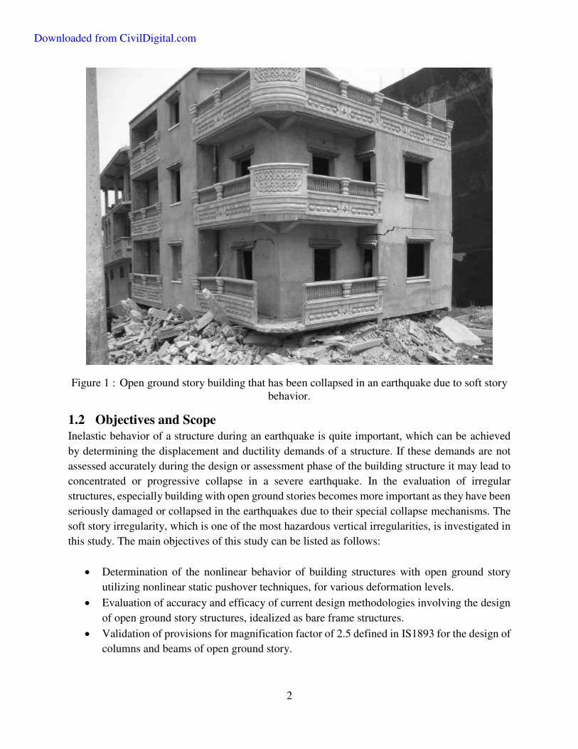
Figures Figure 1 : Open ground story building that has been collapsed in an earthquake due to soft story
behavior........................................................................................................................................... 2
Figure 2 Excessive drift in soft ground story under lateral loading .............................................. 19
Figure 3 Collapse mechanism of a building structure having a soft story .................................... 19 Figure 4: The generalized load deformation relation for nonlinear response ............................... 21
Figure 5: Acceptance criteria on a force versus deformation diagram. ........................................ 22
Figure 6 : A pushover curve of a building structure. .................................................................... 23
Figure 7 : Equivalent Strut Model (a) Masonry Infill Panel (b) Strength Envelope of Masonry
Panel .............................................................................................................................................. 25
Figure 8 : Idealized Pin jointed compression strut model............................................................. 27
Figure 9: Compressive stress-strain curves for masonry .............................................................. 28
Figure 10 Plan of the model representing point of application of pushover loads ....................... 31
Figure 11 : Bare frame model ....................................................................................................... 32
Figure 12 Open Ground story model with diagonal struts ............................................................ 33
Figure 13 : Fully infilled structure with equivalent single struts .................................................. 34
Figure 14 : Idealized M-θ Curves for Hinge Definitions .............................................................. 36
Figure 15: Idealized P-M interaction curve for columns .............................................................. 36
Figure 16: P-M Interaction curve of RC column .......................................................................... 37
Figure 17 : Load Displacement plot for defining Axial Hinges in diagonal struts ....................... 38
Figure 18: Calculation of lateral strength of masonry-infill walls ................................................ 39
Figure 19 : Plastic Hinge Assignments ......................................................................................... 39
Downloaded from CivilDigital.com
ix
Figure 20 : Section Assignments .................................................................................................. 40
Figure 21 : Pushover curve for Model 1 ....................................................................................... 41
Figure 22 : Hinge formation pattern at Ultimate load. .................................................................. 42
Figure 23: Pushover curve for Model 2 ........................................................................................ 43
Figure 24: Hinge formation pattern at Ultimate load.................................................................... 44
Figure 25: Pushover curve for Model 3 ........................................................................................ 45
Figure 26: Hinge formation pattern at Ultimate load.................................................................... 46
Figure 27 : Ground storey members designed for code-specified factors. ................................... 46
Figure 28: Pushover curve for Strengthened Model ..................................................................... 47
Figure 29: Hinge formation pattern at ultimate load .................................................................... 48
Figure 30 : Ground storey Columns designed for code-specified factors .................................... 48
Tables
Table 1 : Moment – Rotation values used for defining Plastic Hinges ........................................ 37
Table 2 : Pushover Summary ........................................................................................................ 49
Downloaded from CivilDigital.com

x
Notations
Notations Description
Vy Lateral force corresponding to yield in Masonry
Vm Maximum post-yield lateral force of Masonry
t The thickness or out of plane dimension of the infill panel
Inclination of Strut at base to horizontal
'mf Masonry prism strength
'm Strain corresponding to prism strength
s Shear strength or cohesion of masonry
dA Area of equivalent strut
dL Length of equivalent strut
c Upper bound or failure normal contact stresses at the column-
infill interface
cf The compressive strength of the masonry
af Compressive stress of infill in its central region
b Contact shear stresses at the beam-infill interface
'h
Height of infill panel
'l Length of the infill panel
We Width of equivalent strut
dm The length of the infill diagonal
Vb Total design base shear
W Seismic weight of the whole building
Ah The design horizontal acceleration spectrum
Z The seismic zone factor
I Importance factor
2R The response reduction factor
aS
g The average response acceleration coefficient
Downloaded from CivilDigital.com
xi
ifT Fundamental natural period
h The total height of the main structure
d Maximum base dimensions of the building along the considered
direction of seismic force
c Neutral axis depth at ultimate moment
θy Yield rotations
θu Ultimate rotations
E Modulus of elasticity
I Moment of inertia
u & y Idealized ultimate and yield curvatures of the section respectively
pl Length of the plastic hinge
Py Idealized yield force in the axial direction
Pm Idealized maximum force in the axial direction
vy Displacement corresponding to Py
vm Displacement corresponding to Pm
Downloaded from CivilDigital.com
1
CHAPTER 1.
1.1 Introduction
Open first story is a typical feature in the modern multistory constructions in urban India. The
parking and commercial areas with higher story heights and less infill walls reduces the stiffness
of the lateral load resisting system at ground story and progressive collapse becomes obvious in a
severe earthquake for such buildings. Though functional planners applaud open ground storey
models in order to facilitate the necessity of parking space in residential and commercial buildings,
such features are critically undesirable in buildings built in seismically active areas. Open ground
floor with increased column height outcomes soft-ground storey, which has been proved to be
highly vulnerable during past major ground motions, Kobe (1994), Bhuj (2001). Jabalpur
earthquake of 22 May 1997 (Jain, et al, 1997) also illustrated the handicap of Indian buildings with
soft first storey. This earthquake was the first one in an urban neighborhood in India and provided
a cause to assess the performance of engineered structures in the country during ground shaking.
The susceptibility of open storey buildings to earthquake induced damages on one hand and the
functional necessity on the other hand marks open ground storey an unavoidable, moreover a
challenging task for structural engineers.
Masonry infill in RC frames acts as a diaphragm in vertical plane that imparts significant lateral
strength and stiffness to RC frames under lateral loads. Infilled frames are also substantially
stronger, but less deformable, than identical bare frames. In symmetric structures with continuous
infilled frames along height, the better stiffness and strength can protect a building from damage
due to excessive lateral drift or insufficient strength. Due to higher stiffness, infill panels could
attract considerably greater forces that can lead to premature failure of panels, and probably of the
whole building. Hence, it is necessary for designers to take into account the effects of infills
masonry in the design of RC structures. The amplified displacement, force and ductility demands
in the ground storey columns in such constructions are neglected when analyzed and designed as
bare frames. Hence, it is of utmost concern to validate the adaptability and performance of open
ground story under the possible action of earthquakes. In order to prevent soft story collapse
mechanisms in the building structures, seismic demands must be determined accurately.
Downloaded from CivilDigital.com
2
Figure 1 : Open ground story building that has been collapsed in an earthquake due to soft story behavior.
1.2 Objectives and Scope
Inelastic behavior of a structure during an earthquake is quite important, which can be achieved
by determining the displacement and ductility demands of a structure. If these demands are not
assessed accurately during the design or assessment phase of the building structure it may lead to
concentrated or progressive collapse in a severe earthquake. In the evaluation of irregular
structures, especially building with open ground stories becomes more important as they have been
seriously damaged or collapsed in the earthquakes due to their special collapse mechanisms. The
soft story irregularity, which is one of the most hazardous vertical irregularities, is investigated in
this study. The main objectives of this study can be listed as follows:
Determination of the nonlinear behavior of building structures with open ground story
utilizing nonlinear static pushover techniques, for various deformation levels.
Evaluation of accuracy and efficacy of current design methodologies involving the design
of open ground story structures, idealized as bare frame structures.
Validation of provisions for magnification factor of 2.5 defined in IS1893 for the design of
columns and beams of open ground story.
Downloaded from CivilDigital.com

3
Three-dimensional RC analytical models are formed and designed conforming to IS 456. These
models are then assessed by exploiting nonlinear static pushover analyses techniques with various
lateral load patterns. The results obtained from analyses are evaluated, considering performance at
various deformation levels, which define the performance of the structures.
1.3 Thesis Organization
This thesis is organized into seven chapters and six appendices. Chapter 1 includes the general
summary of the study. Chapter 2 elucidates previous research on the nonlinear pushover analysis,
analysis of structures with infill panels and soft story behavior in open ground story buildings. In
Chapter 3, the soft story irregularity is explained in the context of open ground story buildings and
code provisions are also described. Detailed explanations on nonlinear member behavior used in
the study and nonlinear pushover method are explicated in Chapter 4. Advanced modeling of infills
using equivalent strut is explained in chapter 5. In Chapter 6, the detailed information about
The analytical models adopted in the analyses
Pushover lateral load patterns
Hinge definitions and
Details of infill idealization,
Which are performed on the model buildings is specified. The assessment and comparison of the
analyses results are given in Chapter 7. Finally, Chapter 8 contains references.
Downloaded from CivilDigital.com
4
CHAPTER 2.
REVIEW OF LITERATURE
The study investigates a full scale multi storey structure with soft ground storey considering the
structural action of infill walls. The literature review has been divided into three parts, specifically,
current advancement in studies on soft storey building and theories on structural behavior of infill
wall panels and their analysis and finally nonlinear push over analysis techniques used for analysis
of structure.
2.1 Soft Storey Structures
Open first storey is an unavoidable feature in many urban multi storey buildings in India. Several
earthquakes in the past, e.g., San Fernando 1971, Northridge 1994, Kobe 1995, have demonstrated
the potential hazard associated with Soft Storey buildings. Major damages in reinforced concrete
and steel buildings in the Hyogoken-Nanbu earthquake, 1995 (AIJ, 1995) [1], and critical hospital
facilities in the San Fernando earthquake of 1971, were attributed to the soft first storey. Alarming
amount of damage to the buildings with open basements for parking has been reported during the
Northridge earthquake of January 17, 1994 [2]
In a developing country like India open ground storey serves increased parking and aesthetic
demands in residential structures. The Indian Standard Code IS1893 (Part I 2010) defines “Soft Storey” as “one in which the lateral stiffness is less than seventy percent of that in the storey above or less than eighty percent of the average lateral stiffness of the stories above”. Indian Standard
also prescribes that “the columns and beam of soft storey are to be designed for 2.5 times the storey shear and moments under seismic loads. As a matter of fact, most Indian buildings, with no
masonry infill walls in the first storey, belong to “buildings with soft first storey.” Though soft
storey is considered as a separation between the ground and the super structure, it reduces stiffness
and increases the ductility demand of the elements under seismic loading and reversal of stresses.
The dynamic response of soft ground storey under earthquake loading is still a topic discussion
and debate among researchers.
The total seismic base shear as experienced by a building during an earthquake is dependent on its
natural period; the seismic force distribution is dependent on the distribution of stiffness and mass
along the height. In structures with open first storey and higher storeys being stiff undergo lesser
inter-storey drifts. Yet, the inter-storey drift in the ground first storey is large. Strength demands
on these columns are also large, as the shear in the first storey is concentrated. For the higher
storeys, the forces in the columns are effectively reduced. Due to the presence of the structures
with abrupt variations in storey stiffness, have irregular lateral force distribution along the height,
which causes locally induced stress concentration, which can adversely affect the performance of
Downloaded from CivilDigital.com

5
structures during ground shaking. Such buildings are required to be analyzed by the dynamic
analysis and designed carefully. Enhanced design of weak/soft-story frame members is done in
different national codes based on empirical or semi-empirical relations. Inadequate literature is
available in support of these relations, demanding an urgent need for more research in this area.
Flexible first storey concept was first proposed by Marta (1929) and was studied further by Green
(1935) and Jacobsen (1938), and commented that soft first storey columns are to be designed to
yield during an earthquake, such that shear forces transmitted to the rest of the structure are
reduced. In such structures, stiff ground storey attracts the seismic energy and upper stories are
less vulnerable to shear forces. This increases the ductility demand strength demand of the ground
storey. Recently Ari Wibowo et. al. [3] explored many features about soft-storey buildings and
their collapse mechanisms, from experimental field study of a five storey building in Melbourne,
concluded that column of the soft-storey are susceptible to large lateral displacements. They also
claimed that there is a significant contribution from the ground storey slab to the lateral stiffness
of the column. Their seismic performance evaluation using a displacement based assessment
showed that the precast soft storey structure would perform satisfactorily in regions of lower to
moderate seismicity, whilst the performance would be compromised in regions of high seismicity,
where catastrophic collapse through p-Δ effects could be expected due to the excessive
displacement demands. In addition, an in situ reinforced concrete system would perform
significantly worse due to the reduced drift capacity associated with column flexure deformations
rather than rigid body rocking of the precast system.
Y.L Mo and Y.F. Chang (1993) found that soft storey system of base isolation have drawbacks,
unless used with sliding bearing system during ground motions. Arlekar, Jain and Murty [4]carried
out a study to evaluate error involved in modeling such buildings as complete bare frames, ignoring
the influence of infills in the upper storeys. An example building with different analytical models
were studied and stiffness balancing methods were proposed and it was concluded that stiffness
demand of open ground storey can be fulfilled by providing stiffer columns in the open ground
storey or by providing a concrete service core in the building, to serve the lateral drift demand. Fardis [5]carried out study on the design of infilled RC structures, following conclusions were
made; Overall influence of infills are found to be beneficial when infills with regular distribution
is adopted; provisions of EC8 were found to be too conservative while designing the structure as
bare suffices (their main effect is on energy dissipation and not response period); The only adverse
effect for regular structures is a tendency for drift concentration in the bottom storey, though
deformations in that storey are well below that required for a soft storey mechanism. For structures
with an open bottom storey, the concentration of drift and structural damage of the columns
become significant. In structures with infilled panels along two adjacent sides, the response can be
quasi -rotational. As a result the far corner columns may need to be designed for the simultaneous
peaks for the two directional components. In all other respects the RC frame may be designed as
bare.
Downloaded from CivilDigital.com
6
2.2 Masonry Infill in RC Frames
RC framed buildings are usually analyzed and designed as bare frames, neglecting the strength
and stiffness contribution of the infill walls. The behavior of infill frames and bare frames are
different under the action of seismic lateral loading. Understanding the response and behavior of
infills under earthquake makes it possible to exploit the benefits of infills in a rational manner. In
addition, construction of infill is cheaper because it uses locally available material. It has good
sound & heat insulation and waterproofing properties, ensuing in better occupant comforts and
economy. It has been realized by many researchers that the infill panels have significant effects on
the structural and mechanical behavior of RC frames; hence, it’s been considered that infill
changes the stiffness, ultimate capacity and failure mode of RC framed structures to a considerable
extent. Masonry infill walls confined by reinforced concrete RC frames on all four sides play a
vital role in resisting the lateral seismic loads on buildings.
Since masonry infill increases the strength, lateral stiffness and dead weight of a framed structure
it will also change the dynamic characteristics of the structure. It has been proven that infill causes
considerable increase in global stiffness. On the other hand, potentially negative effects may occur
such as torsional effects induced by in plan-irregularities, soft-storey effects caused by
irregularities and short column effects, Nollet and Smith, [6]. Even though the effect of infill is
ignored by structural engineers, it cannot always end up with a conservative design because
1. Infill panels changes the structural natural period, and
2. Extensive increase of axial force in columns and beams due to diagonal strut behavior
leading to lack of ductility capacity in structure.
Simplified macro models (equivalent strut models) are formed, capable of replacing commonest
failure modes of failure in masonry panels, which should be the most practical concern of an
engineer.
An early contribution to understanding the complex nature of masonry infill frames was introduced
in 1956 by Polyakov [7] with a concept of equivalent struts in which infill panels was considered
to behave as a braced frame with diagonal compression struts. He proposed that stresses from
frame to the infill are only transferred in the compression zone of the infill-frame interface, with a
distribution more like a diagonally braced system than a homogenous shear wall. B.Srinivas and
B.K.Raghu Prasad [8]studied response of a five story reinforced masonry infill and bare frame
building model, designed according to IS 1893 codal provisions under three strong motion records
from Imperial Valley (1979), Northridge (1994) and San Fernando (1971) earthquakes. The
building the infill walls are modeled by equivalent strut approach and the bottom storey of the
building kept openly for considering the realistic behavior of the presently existing buildings in
India. Nonlinear static and nonlinear dynamic analyses were performed to study the response
behavior of the buildings. Results showed that presence of infill walls greatly contributes the
stiffness to lateral loads and the deviation in storey response quantities (displacement, storey shear)
Downloaded from CivilDigital.com
7
are decreasing due to the infill masonry walls but the response quantities at the soft storey level is
significantly large. These effects, however, were not found to be significant in the bare frame
model. It was also found that the location of plastic hinges concentrated at bottom stories causes
severe structural damage in infilled frame structure at first storey but in the case of bare frame
model hinges spread throughout the height and influence of infill walls on static and dynamic
behavior of structures causes a decrease in storey shear and inter storey drifts.
Hossein Mostafaei and Toshimi Kabeyasawa [9]studied the Effect of Infill Masonry Walls on the
Seismic Response of Reinforced Concrete Buildings subjected to the Bam Earthquake. The
response simulations were performed for different categories of bare frame and infilled frame. A
method was developed to model infill walls with or without openings. The outcomes of the
analyses were compared to damage and residual cracks observed on the masonry infill walls and
reasonable correlations were obtained between analytical and observed results. It was concluded
that the presence of masonry infill walls is the main reason for the nearly linear responses of the
building during the earthquake.
Tso-Chien Pan et. al [10]carried out full-scale ambient vibration test on a typical high-rise
residential building and it was found that adding the brick partition walls increases the natural
frequencies of a building, from 0.71 to 1.75 Hz when brick walls were aligned along the
longitudinal direction, since the stiffness in the longitudinal direction was increased dramatically.
Thus, the longitudinal direction becomes the stiffer direction, and the fundamental mode of the
building switches to the transverse direction, which was consistent with the observation made
during the ambient vibration tests. The modal frequencies and the mode shapes of the model with
the brick infill walls match well with some of the building dynamic characteristics measured.
Therefore, in order to achieve a good correlation between the numerical and the experimental
results, the non-structural brick infill walls need to be included in the model. It was also suggested
that that plane stress elements can model the brick infill walls well in the small strain situation.
Kaushik [11] made comparative study among the different seismic codes and found inconsistency
in the consideration of infill and reported that most codes do not consider infill due to its brittle
nature of failure and lack of adequate information. The validity of different macro-models
consisting of 4- node shear panels, 4-node plane stress element and the higher order 8-node plane
stress element were studied by Doudoumis and Mitsopoulou [12] and reported inaccuracy in
results of macro models. Singh, Paul et al. [13] had developed a method to predict the formation
of plastic hinges and cracks in the infill panels under static and dynamic loads by using 3-noded
frame element, 8-noded isoparametric element and 6 noded interface element for frame member,
infill panel and the interface element respectively.
The study showed good agreement with the experimental results, especially in terms of failure load
and the strut width. Doudoumis [14]studied the importance of contact condition between the infill
and frame members on a single storey Finite element model. It was reported that the friction
Downloaded from CivilDigital.com
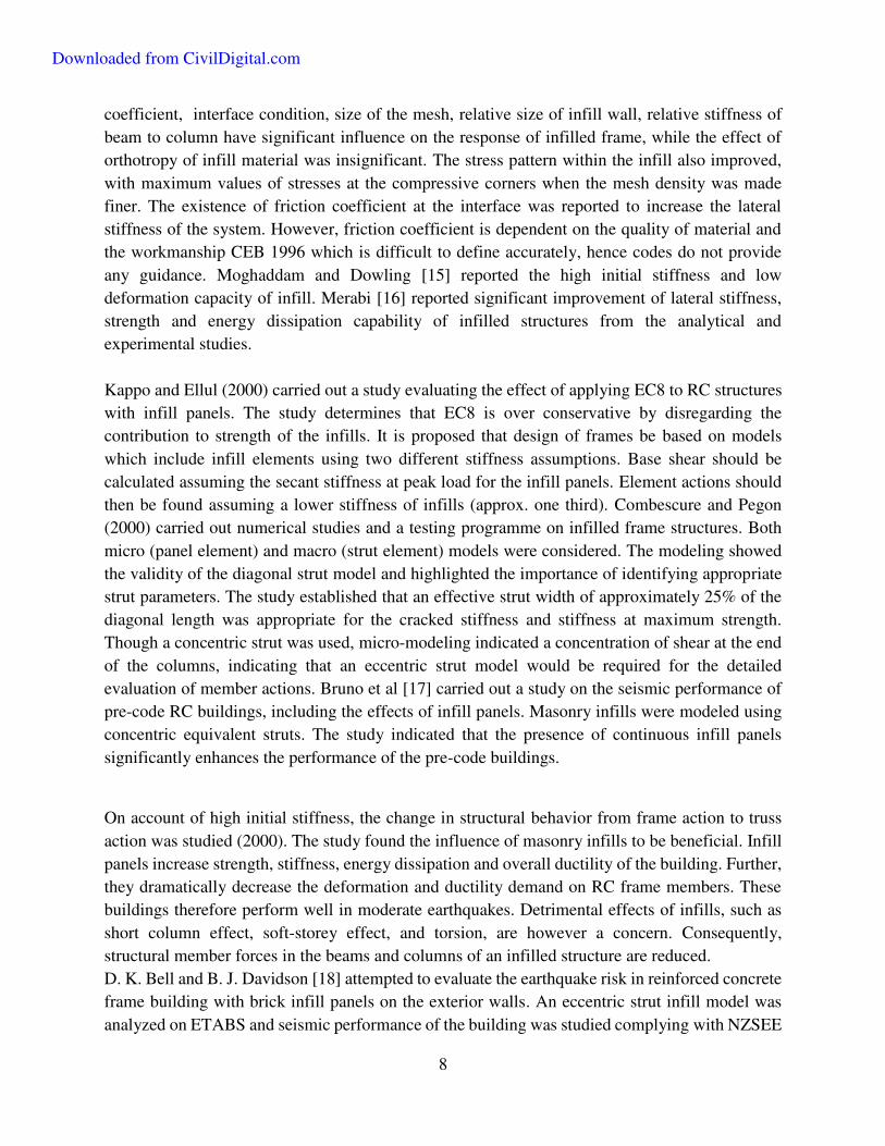
8
coefficient, interface condition, size of the mesh, relative size of infill wall, relative stiffness of
beam to column have significant influence on the response of infilled frame, while the effect of
orthotropy of infill material was insignificant. The stress pattern within the infill also improved,
with maximum values of stresses at the compressive corners when the mesh density was made
finer. The existence of friction coefficient at the interface was reported to increase the lateral
stiffness of the system. However, friction coefficient is dependent on the quality of material and
the workmanship CEB 1996 which is difficult to define accurately, hence codes do not provide
any guidance. Moghaddam and Dowling [15] reported the high initial stiffness and low
deformation capacity of infill. Merabi [16] reported significant improvement of lateral stiffness,
strength and energy dissipation capability of infilled structures from the analytical and
experimental studies.
Kappo and Ellul (2000) carried out a study evaluating the effect of applying EC8 to RC structures
with infill panels. The study determines that EC8 is over conservative by disregarding the
contribution to strength of the infills. It is proposed that design of frames be based on models
which include infill elements using two different stiffness assumptions. Base shear should be
calculated assuming the secant stiffness at peak load for the infill panels. Element actions should
then be found assuming a lower stiffness of infills (approx. one third). Combescure and Pegon
(2000) carried out numerical studies and a testing programme on infilled frame structures. Both
micro (panel element) and macro (strut element) models were considered. The modeling showed
the validity of the diagonal strut model and highlighted the importance of identifying appropriate
strut parameters. The study established that an effective strut width of approximately 25% of the
diagonal length was appropriate for the cracked stiffness and stiffness at maximum strength.
Though a concentric strut was used, micro-modeling indicated a concentration of shear at the end
of the columns, indicating that an eccentric strut model would be required for the detailed
evaluation of member actions. Bruno et al [17] carried out a study on the seismic performance of
pre-code RC buildings, including the effects of infill panels. Masonry infills were modeled using
concentric equivalent struts. The study indicated that the presence of continuous infill panels
significantly enhances the performance of the pre-code buildings.
On account of high initial stiffness, the change in structural behavior from frame action to truss
action was studied (2000). The study found the influence of masonry infills to be beneficial. Infill
panels increase strength, stiffness, energy dissipation and overall ductility of the building. Further,
they dramatically decrease the deformation and ductility demand on RC frame members. These
buildings therefore perform well in moderate earthquakes. Detrimental effects of infills, such as
short column effect, soft-storey effect, and torsion, are however a concern. Consequently,
structural member forces in the beams and columns of an infilled structure are reduced.
D. K. Bell and B. J. Davidson [18] attempted to evaluate the earthquake risk in reinforced concrete
frame building with brick infill panels on the exterior walls. An eccentric strut infill model was
analyzed on ETABS and seismic performance of the building was studied complying with NZSEE
Downloaded from CivilDigital.com
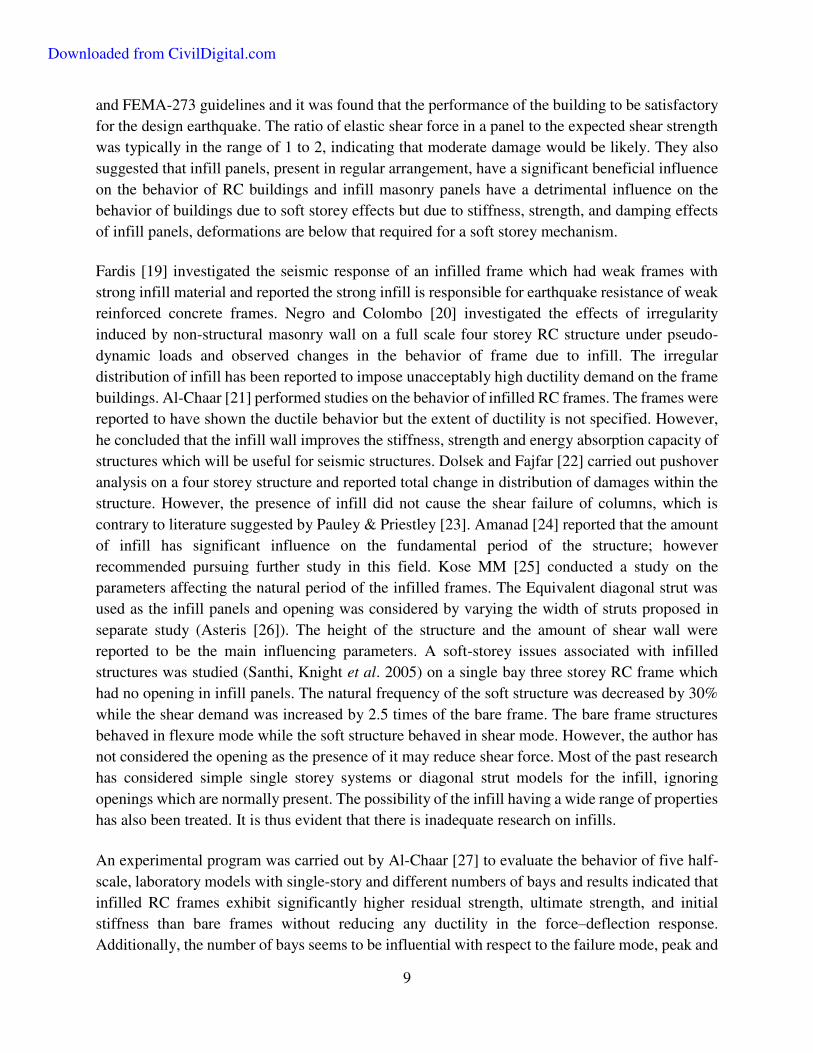
9
and FEMA-273 guidelines and it was found that the performance of the building to be satisfactory
for the design earthquake. The ratio of elastic shear force in a panel to the expected shear strength
was typically in the range of 1 to 2, indicating that moderate damage would be likely. They also
suggested that infill panels, present in regular arrangement, have a significant beneficial influence
on the behavior of RC buildings and infill masonry panels have a detrimental influence on the
behavior of buildings due to soft storey effects but due to stiffness, strength, and damping effects
of infill panels, deformations are below that required for a soft storey mechanism.
Fardis [19] investigated the seismic response of an infilled frame which had weak frames with
strong infill material and reported the strong infill is responsible for earthquake resistance of weak
reinforced concrete frames. Negro and Colombo [20] investigated the effects of irregularity
induced by non-structural masonry wall on a full scale four storey RC structure under pseudo-
dynamic loads and observed changes in the behavior of frame due to infill. The irregular
distribution of infill has been reported to impose unacceptably high ductility demand on the frame
buildings. Al-Chaar [21] performed studies on the behavior of infilled RC frames. The frames were
reported to have shown the ductile behavior but the extent of ductility is not specified. However,
he concluded that the infill wall improves the stiffness, strength and energy absorption capacity of
structures which will be useful for seismic structures. Dolsek and Fajfar [22] carried out pushover
analysis on a four storey structure and reported total change in distribution of damages within the
structure. However, the presence of infill did not cause the shear failure of columns, which is
contrary to literature suggested by Pauley & Priestley [23]. Amanad [24] reported that the amount
of infill has significant influence on the fundamental period of the structure; however
recommended pursuing further study in this field. Kose MM [25] conducted a study on the
parameters affecting the natural period of the infilled frames. The Equivalent diagonal strut was
used as the infill panels and opening was considered by varying the width of struts proposed in
separate study (Asteris [26]). The height of the structure and the amount of shear wall were
reported to be the main influencing parameters. A soft-storey issues associated with infilled
structures was studied (Santhi, Knight et al. 2005) on a single bay three storey RC frame which
had no opening in infill panels. The natural frequency of the soft structure was decreased by 30%
while the shear demand was increased by 2.5 times of the bare frame. The bare frame structures
behaved in flexure mode while the soft structure behaved in shear mode. However, the author has
not considered the opening as the presence of it may reduce shear force. Most of the past research
has considered simple single storey systems or diagonal strut models for the infill, ignoring
openings which are normally present. The possibility of the infill having a wide range of properties
has also been treated. It is thus evident that there is inadequate research on infills.
An experimental program was carried out by Al-Chaar [27] to evaluate the behavior of five half-
scale, laboratory models with single-story and different numbers of bays and results indicated that
infilled RC frames exhibit significantly higher residual strength, ultimate strength, and initial
stiffness than bare frames without reducing any ductility in the force–deflection response.
Additionally, the number of bays seems to be influential with respect to the failure mode, peak and
Downloaded from CivilDigital.com
10
residual capacity and shear stress distribution. Moghaddam and Dowling [15] experimentally
showed that masonry infill walls have a very high initial lateral stiffness and low deformability.
Murty and Jain [28] established that introduction of infills in RC frames changes the lateral load
transfer mechanism of the structure from predominant frame action to predominant truss action,
which in turn reduces bending moments and increase the axial forces in the frame members.
Kasim Armagan et. al (2007) studied, a 3-story R/C frame structure with different amount of
masonry infill walls to investigate the effects of infill walls on earthquake response of these type
of structures. Diagonal strut approach was assumed for modeling masonry infill walls. Pushover
curves are found for the structures using nonlinear and established that the stability and integrity
of reinforced concrete frames are enhanced with masonry infill walls and presence of masonry
infill wall also alters displacements and base shear of the frame. Uneven distributions of masonry
infill walls in elevation can cause unacceptably elastic displacement in the soft storey frame. The
performance of buildings with infilled walls can be predicted by simplified diagonal models.
Comparatively simple and accurate method can be obtained by using these models for including
the effects of the infill walls.
Damage of masonry infilled RC frames subjected to blasting induced ground excitations was
assessed by Hong Hao et. al [29] and suggested that the influence of masonry infill on frame
response depends on the physical properties as well as the geometry of the wall. The stability and
integrity of RC frames are enhanced with a masonry infill wall. Besides the response level, the
presence of masonry infill also alters the damage pattern of the RC frame. Neglecting such effects
in the damage assessment of the masonry infilled frame structures will lead to unreliable results.
In the research work of Dorji and Thambiratnam [30] it was found that the strength of the infill
and the therefore the Youngs modulus has a significant influence on the overall performance of
structure. The structural response of the building such as roof displacements, inter storey drift ratio
and stress in the infill decreases as Youngs modulus of infill material increases. They suggested
that the opening size of the infill has vital effect on the fundamental period hence on the member
forces. Finally they found that there won’t be much difference in the performance of the structure if the infill elastic modulus is less than 5000 N/mm2.
Recently, L. Su & J. Shi [31], researchers from china proposed a new nonlinear methodology for
analyzing RC framed structures with infill, DBELA (Displacement Based Loss Assessment
Methodology) considering both micro and macro models. They investigated yield displacement,
period-height relationships and hysteretic characteristics of infilled RC frames and concluded that
masonry infill can increase earthquake energy dissipation and can reduce yield displacement and
corresponding yield period, compared to traditional beam sway structure; it was found that the
new methodology can precisely predict maximum displacement for both yield and post-yield
limits.
Downloaded from CivilDigital.com

11
2.2.1 Infill Panels with Openings
Window and door openings are inevitable parts of infill walls due to functional causes.
Publications like FEMA-273 and ATC-40 contain provisions for the calculation of stiffness of
solid infilled frames mainly by modeling infill panels as a “diagonal strut.” But provisions are not
provided for infilled frames with openings. Various analytical models developed to estimate lateral
stiffness and strength of the infilled frames with openings is equivalent frame model, single
diagonal strut model finally multi-diagonal strut model. Equivalent frame model is based on the
theory of equivalent frame in which members have properties of composite sections of the actual
structure (Liauw [32], Kodur et al. 1998). The equivalent diagonal strut model is the most
simplified yet practically accurate macro-model, usually done by modeling the infill panel as a
single diagonal strut connecting two compressive diagonal corners. Key to this method lies in
calculation of effective width of equivalent diagonal strut. Several attempts have been made to
establish the effective width of diagonal strut for infilled frames without opening (Smith and Carter
1969, Holmes 1961, Mainstone 1971, Liauw and Kwan 1984 and Priestley 1992). They noticed
that frames without infill fail in flexure, with simple four-hinge mechanism, while frames with
infill fail in shear or in the tension column.
Model work by Fiorato et al. in [33] clearly demonstrated that infill substantially augments a
frame’s post peak behavior. Quasistatic, cyclic work on multiple story models concluded that
lateral strength and energy dissipation capacity were greatly improved, as well as lateral stiffness.
In attempts to try to quantify these phenomena, it was found that Stafford-Smith and Carter’s [34]
diagonal-strut approach reasonably predicted stiffness, but not peak strength. A study by Mehrabi
et al [35] on half scale frames subjected to in-plane loading also demonstrated substantial strength
and stiffness gains, as well as improved energy dissipation. Their research concentrated on various
levels of infill and boundary frame strength as predictors for damage onset at different levels of
story drift. Gulan and Sozen [36] proposed a seismic vulnerability ranking method for existing
infill RC structures based on panel or column geometry. It was found that valuation of the filler
contribution to the frame stiffness should be based on the compression/tension strength of the
mortar.
The effective width of diagonal strut for infilled frame without opening may be reduced by a
reduction factor to simulate the presence of openings of various aspect ratios in the infilled frame
was studied by Durrani and Luo [37], Al-Chaar [38]. Multi-strut models were proposed to
represent the local effects due to the presence of openings (Thiruvengadam 1985, White et. al
1999, Al-Chaar 2002). The published researches on infilled frames point to a need for suitable
quantitative design provisions to account for effect of openings. The relation for strut-width
proposed by Durrani and Luo [37] can be used to obtain the lateral stiffness of infilled frames due
to presence of central opening, developed numerically on the basis of Finite Element (FE) analyses
only and was not verified with experimental results. The expression established by Durrani and
Luo are too complex for use in design office because these account for beam stiffness, column
stiffness and infill panel aspect ratios. However, strut-width proposed by Al-Chaar [38]is simpler
Downloaded from CivilDigital.com
12
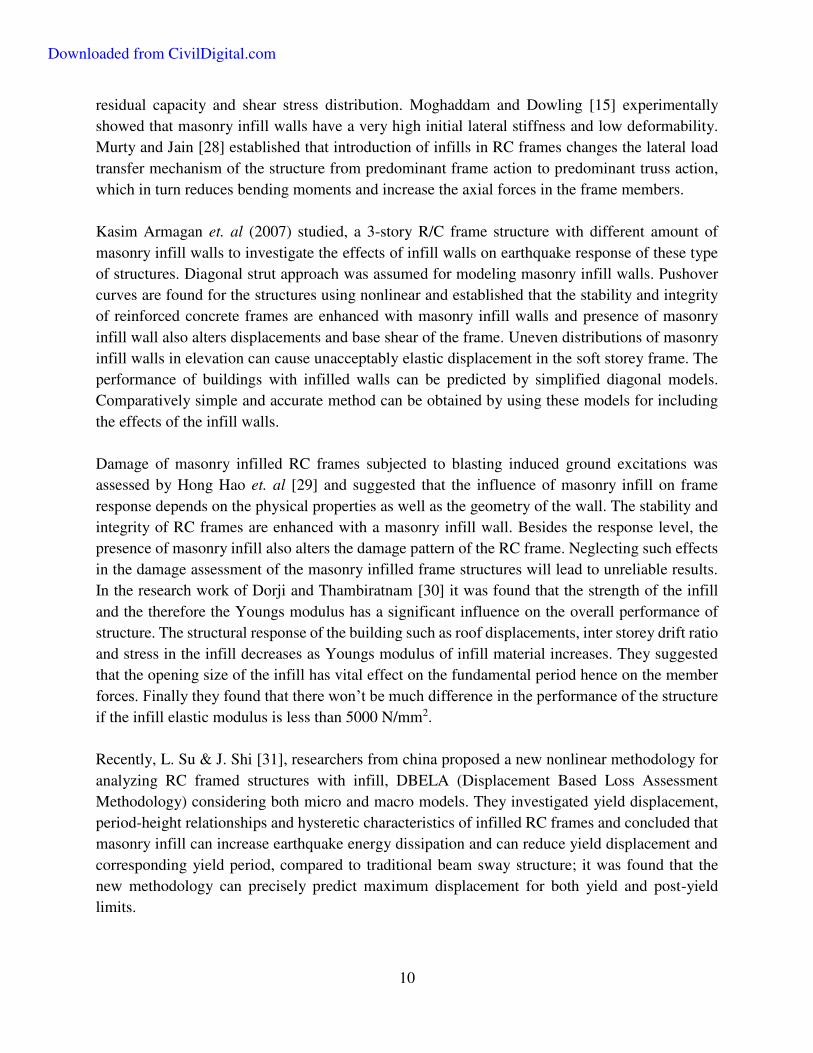
than that proposed by Durrani and Luo [37]. Pushover analysis of infilled frame with openings by
Al-Chaar’s width of strut predicts in-plane strength but underestimates the initial lateral stiffness.
Hence, modification factors were proposed by Al-Chaar to obtain a reasonable value of initial
stiffness directly from the pushover curve.
It was proposed by Holmes [39] that the presence of central opening can be considered by reducing
the effective width through a reduction factor, Rw=1−2.6αco, where αco=ratio of the area of opening
to the area of the infill. Reduction factor for effective width of diagonal strut over that of the solid
reinforced concrete infilled frame to calculate its initial lateral stiffness was proposed by studying
seven specimens of infilled frame, when a central window opening is present, by Goutam Mondal
(2006). It was established that the effect of opening on the initial lateral stiffness of infilled frames
should be neglected if the area of opening is less than 5% of the area of the infill panel and strut-
width reduction factor should be set to one, the frame is to be examined as a solid infilled frame.
Influence of infill on the initial lateral stiffness of infilled frame can be neglected if the area of
opening exceeds 40% of the area of the infill panel and hence the strut-width reduction factor be
set to zero, in other words the frame is to be analyzed as a bare frame.
2.3 Nonlinear Static Analysis Methods
Nonlinear analyses are realized to sketch pushover curves and results are presented in comparison
and the effects of irregular configuration of masonry infill wall on the performance of the structure
are established. From the pushover curves, relative story displacements, story displacements,
maximum plastic rotations are calculated. Regarding with the analysis results, effects of
irregularities are obtained in the structural behavior during ground motions. Nonlinear Structural
analyses are to be used to determine the earthquake behavior of structures with infill walls.
Nonlinear analyses are getting improved and so many methods are developed in nonlinear
structural analyses (Atımtay, 2000; 2001). The aim of the nonlinear structural analyses is to
determine and control the performance of the structure under earthquake. Benefit of pushover
analysis is that it is capable of locating the most vulnerable part of the structure under lateral
loading. It provides details that cannot be obtained from elastic analyses, strength and ductility of
structure. In the analysis of the inelastic behavior of the building structures, there are two common methods
that are based on the nonlinear static pushover analysis. Capacity Spectrum method, which is also
referred in [40], is one of the most widespread methods used for the analysis of buildings. Which
was developed by freeman et.al, in this method, the structural capacity curve is calculated and
compared with the demand spectrum. A performance point lies on the capacity spectrum and
therefore the demand spectrum is obtained for performance analysis of the structure. The second
method, that is named Displacement coefficient method that is delineated in FEMA-356 [41], is
based on the displacement modification factors used for modifying the elastic spectral
displacement of the same SDOF system.
Downloaded from CivilDigital.com
13
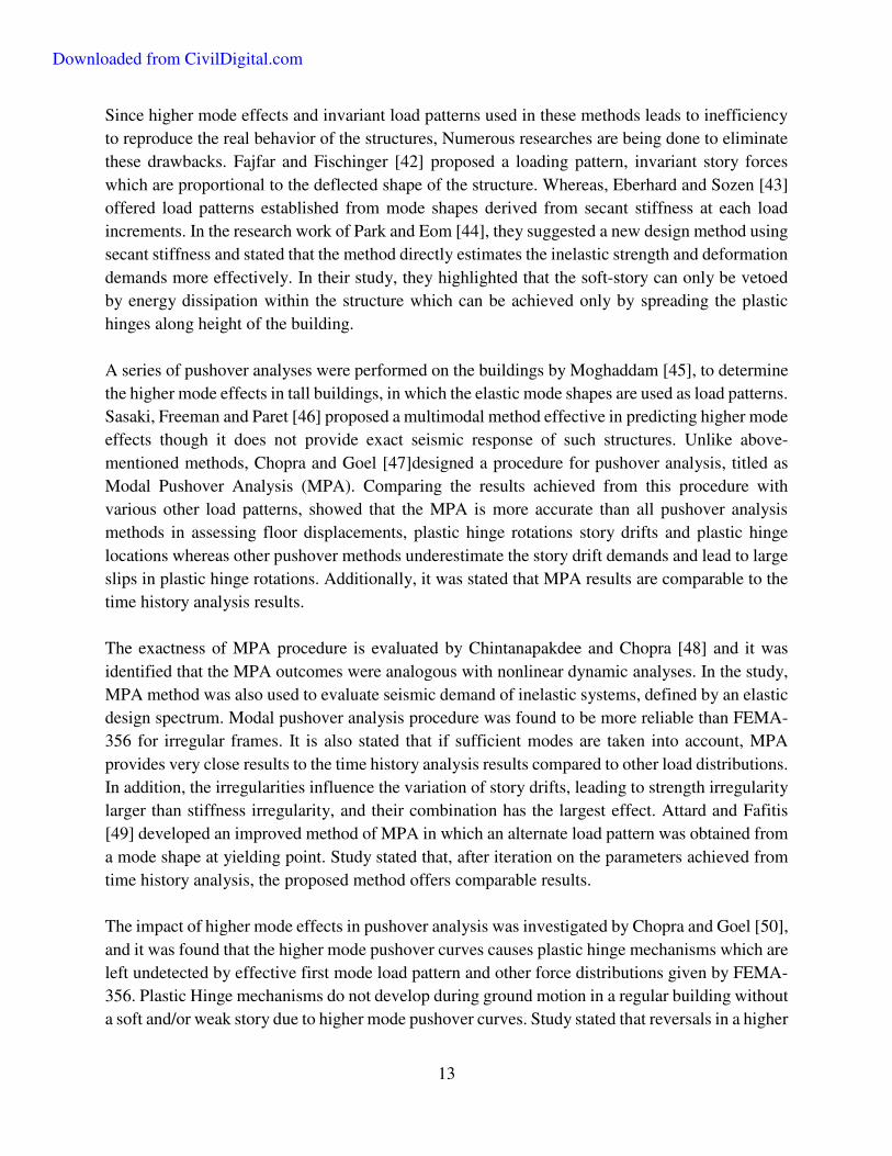
Since higher mode effects and invariant load patterns used in these methods leads to inefficiency
to reproduce the real behavior of the structures, Numerous researches are being done to eliminate
these drawbacks. Fajfar and Fischinger [42] proposed a loading pattern, invariant story forces
which are proportional to the deflected shape of the structure. Whereas, Eberhard and Sozen [43]
offered load patterns established from mode shapes derived from secant stiffness at each load
increments. In the research work of Park and Eom [44], they suggested a new design method using
secant stiffness and stated that the method directly estimates the inelastic strength and deformation
demands more effectively. In their study, they highlighted that the soft-story can only be vetoed
by energy dissipation within the structure which can be achieved only by spreading the plastic
hinges along height of the building.
A series of pushover analyses were performed on the buildings by Moghaddam [45], to determine
the higher mode effects in tall buildings, in which the elastic mode shapes are used as load patterns.
Sasaki, Freeman and Paret [46] proposed a multimodal method effective in predicting higher mode
effects though it does not provide exact seismic response of such structures. Unlike above-
mentioned methods, Chopra and Goel [47]designed a procedure for pushover analysis, titled as
Modal Pushover Analysis (MPA). Comparing the results achieved from this procedure with
various other load patterns, showed that the MPA is more accurate than all pushover analysis
methods in assessing floor displacements, plastic hinge rotations story drifts and plastic hinge
locations whereas other pushover methods underestimate the story drift demands and lead to large
slips in plastic hinge rotations. Additionally, it was stated that MPA results are comparable to the
time history analysis results.
The exactness of MPA procedure is evaluated by Chintanapakdee and Chopra [48] and it was
identified that the MPA outcomes were analogous with nonlinear dynamic analyses. In the study,
MPA method was also used to evaluate seismic demand of inelastic systems, defined by an elastic
design spectrum. Modal pushover analysis procedure was found to be more reliable than FEMA-
356 for irregular frames. It is also stated that if sufficient modes are taken into account, MPA
provides very close results to the time history analysis results compared to other load distributions.
In addition, the irregularities influence the variation of story drifts, leading to strength irregularity
larger than stiffness irregularity, and their combination has the largest effect. Attard and Fafitis
[49] developed an improved method of MPA in which an alternate load pattern was obtained from
a mode shape at yielding point. Study stated that, after iteration on the parameters achieved from
time history analysis, the proposed method offers comparable results.
The impact of higher mode effects in pushover analysis was investigated by Chopra and Goel [50],
and it was found that the higher mode pushover curves causes plastic hinge mechanisms which are
left undetected by effective first mode load pattern and other force distributions given by FEMA-
356. Plastic Hinge mechanisms do not develop during ground motion in a regular building without
a soft and/or weak story due to higher mode pushover curves. Study stated that reversals in a higher
Downloaded from CivilDigital.com
14
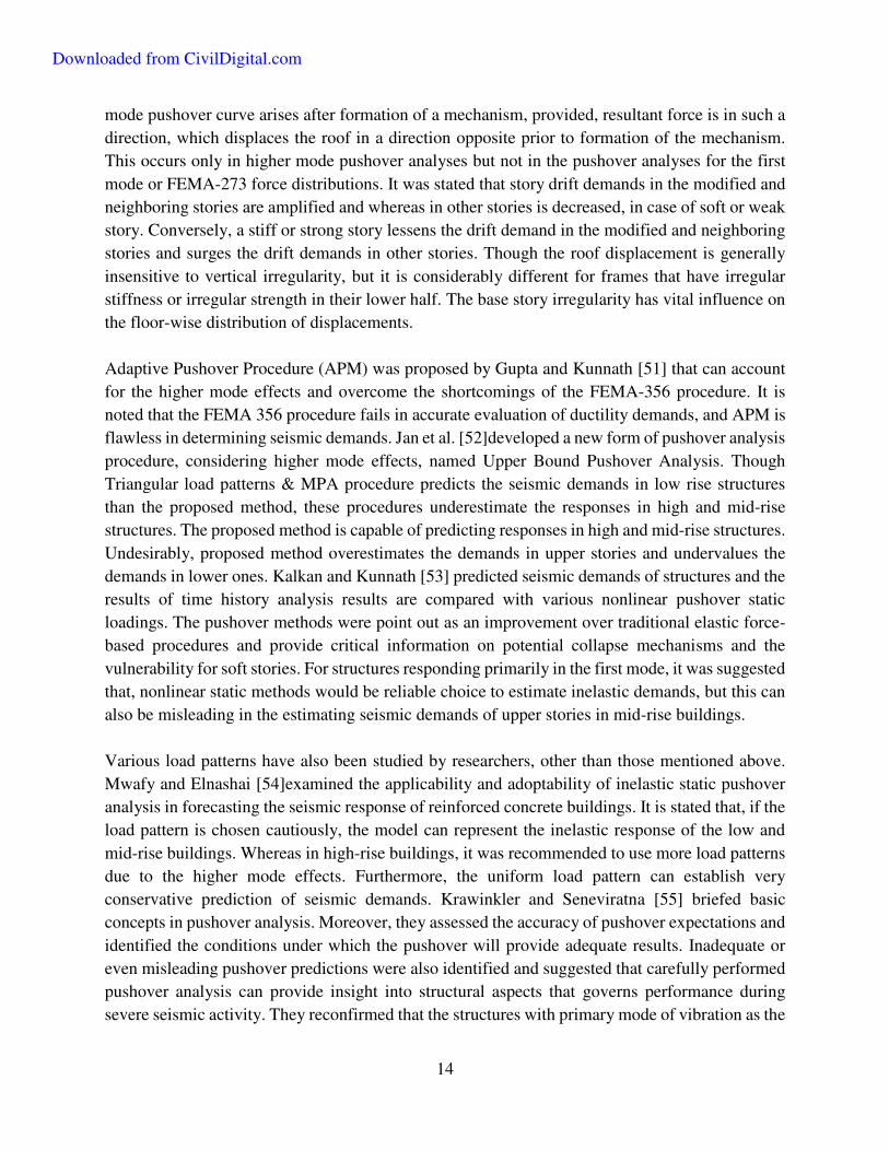
mode pushover curve arises after formation of a mechanism, provided, resultant force is in such a
direction, which displaces the roof in a direction opposite prior to formation of the mechanism.
This occurs only in higher mode pushover analyses but not in the pushover analyses for the first
mode or FEMA-273 force distributions. It was stated that story drift demands in the modified and
neighboring stories are amplified and whereas in other stories is decreased, in case of soft or weak
story. Conversely, a stiff or strong story lessens the drift demand in the modified and neighboring
stories and surges the drift demands in other stories. Though the roof displacement is generally
insensitive to vertical irregularity, but it is considerably different for frames that have irregular
stiffness or irregular strength in their lower half. The base story irregularity has vital influence on
the floor-wise distribution of displacements.
Adaptive Pushover Procedure (APM) was proposed by Gupta and Kunnath [51] that can account
for the higher mode effects and overcome the shortcomings of the FEMA-356 procedure. It is
noted that the FEMA 356 procedure fails in accurate evaluation of ductility demands, and APM is
flawless in determining seismic demands. Jan et al. [52]developed a new form of pushover analysis
procedure, considering higher mode effects, named Upper Bound Pushover Analysis. Though
Triangular load patterns & MPA procedure predicts the seismic demands in low rise structures
than the proposed method, these procedures underestimate the responses in high and mid-rise
structures. The proposed method is capable of predicting responses in high and mid-rise structures.
Undesirably, proposed method overestimates the demands in upper stories and undervalues the
demands in lower ones. Kalkan and Kunnath [53] predicted seismic demands of structures and the
results of time history analysis results are compared with various nonlinear pushover static
loadings. The pushover methods were point out as an improvement over traditional elastic force-
based procedures and provide critical information on potential collapse mechanisms and the
vulnerability for soft stories. For structures responding primarily in the first mode, it was suggested
that, nonlinear static methods would be reliable choice to estimate inelastic demands, but this can
also be misleading in the estimating seismic demands of upper stories in mid-rise buildings.
Various load patterns have also been studied by researchers, other than those mentioned above.
Mwafy and Elnashai [54]examined the applicability and adoptability of inelastic static pushover
analysis in forecasting the seismic response of reinforced concrete buildings. It is stated that, if the
load pattern is chosen cautiously, the model can represent the inelastic response of the low and
mid-rise buildings. Whereas in high-rise buildings, it was recommended to use more load patterns
due to the higher mode effects. Furthermore, the uniform load pattern can establish very
conservative prediction of seismic demands. Krawinkler and Seneviratna [55] briefed basic
concepts in pushover analysis. Moreover, they assessed the accuracy of pushover expectations and
identified the conditions under which the pushover will provide adequate results. Inadequate or
even misleading pushover predictions were also identified and suggested that carefully performed
pushover analysis can provide insight into structural aspects that governs performance during
severe seismic activity. They reconfirmed that the structures with primary mode of vibration as the
Downloaded from CivilDigital.com
15
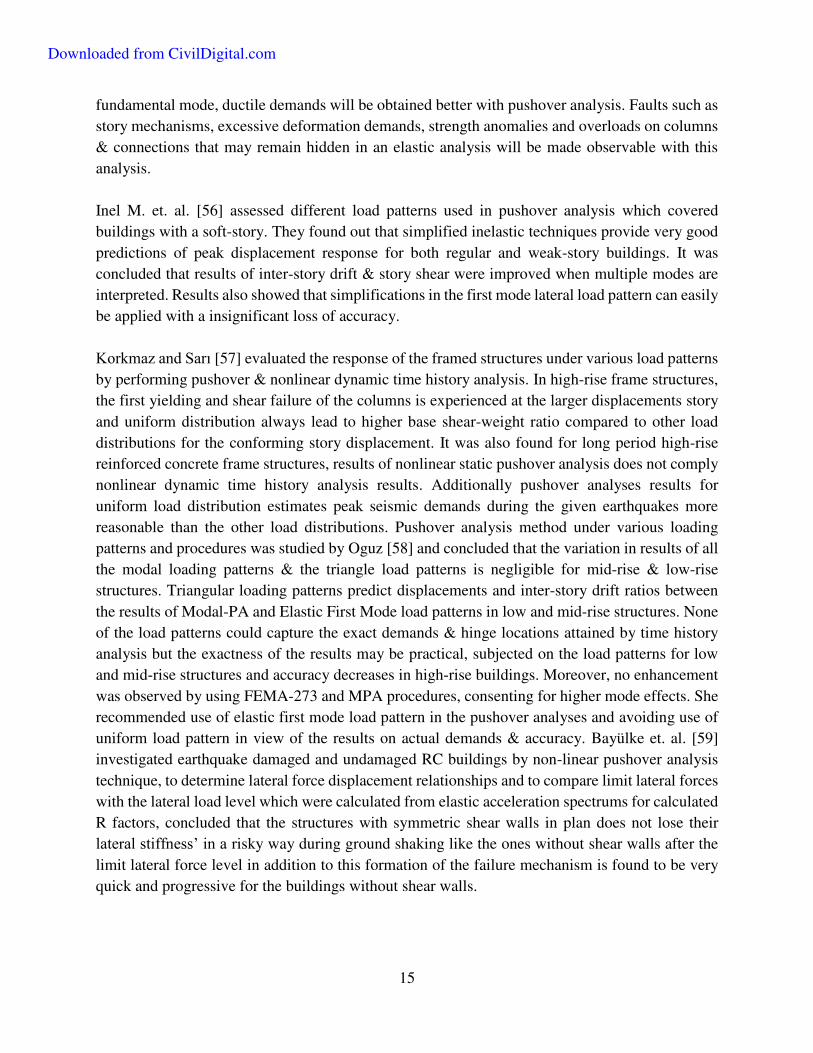
fundamental mode, ductile demands will be obtained better with pushover analysis. Faults such as
story mechanisms, excessive deformation demands, strength anomalies and overloads on columns
& connections that may remain hidden in an elastic analysis will be made observable with this
analysis.
Inel M. et. al. [56] assessed different load patterns used in pushover analysis which covered
buildings with a soft-story. They found out that simplified inelastic techniques provide very good
predictions of peak displacement response for both regular and weak-story buildings. It was
concluded that results of inter-story drift & story shear were improved when multiple modes are
interpreted. Results also showed that simplifications in the first mode lateral load pattern can easily
be applied with a insignificant loss of accuracy.
Korkmaz and Sarı [57] evaluated the response of the framed structures under various load patterns
by performing pushover & nonlinear dynamic time history analysis. In high-rise frame structures,
the first yielding and shear failure of the columns is experienced at the larger displacements story
and uniform distribution always lead to higher base shear-weight ratio compared to other load
distributions for the conforming story displacement. It was also found for long period high-rise
reinforced concrete frame structures, results of nonlinear static pushover analysis does not comply
nonlinear dynamic time history analysis results. Additionally pushover analyses results for
uniform load distribution estimates peak seismic demands during the given earthquakes more
reasonable than the other load distributions. Pushover analysis method under various loading
patterns and procedures was studied by Oguz [58] and concluded that the variation in results of all
the modal loading patterns & the triangle load patterns is negligible for mid-rise & low-rise
structures. Triangular loading patterns predict displacements and inter-story drift ratios between
the results of Modal-PA and Elastic First Mode load patterns in low and mid-rise structures. None
of the load patterns could capture the exact demands & hinge locations attained by time history
analysis but the exactness of the results may be practical, subjected on the load patterns for low
and mid-rise structures and accuracy decreases in high-rise buildings. Moreover, no enhancement
was observed by using FEMA-273 and MPA procedures, consenting for higher mode effects. She
recommended use of elastic first mode load pattern in the pushover analyses and avoiding use of
uniform load pattern in view of the results on actual demands & accuracy. Bayülke et. al. [59]
investigated earthquake damaged and undamaged RC buildings by non-linear pushover analysis
technique, to determine lateral force displacement relationships and to compare limit lateral forces
with the lateral load level which were calculated from elastic acceleration spectrums for calculated
R factors, concluded that the structures with symmetric shear walls in plan does not lose their
lateral stiffness’ in a risky way during ground shaking like the ones without shear walls after the
limit lateral force level in addition to this formation of the failure mechanism is found to be very
quick and progressive for the buildings without shear walls.
Downloaded from CivilDigital.com

16
Polat et.al. [60], did a case study on the conservative retrofitting with linear analysis by assessing
the seismic demands and cost requirements attained by linear analysis was found to be irrational
and the usages of more realistic analysis methods was strongly suggested in such cases. In a similar
study, Hasgür et al. [61] pointed out expected damages due to destructive earthquakes &
determined the relationships and properties of seismic damage indices by non-linear analysis for
RC building structures with elements of various bending shear, yield capacities and corresponding
pre and post strengthening curvatures. He concluded that retrofitting by using the results of the
nonlinear analysis approaches were more accurate & better in cost concerns.
Türker et. al. [62] studied a set of models considering the effects of the in-fills. Considering in-
fills in the nonlinear pushover analysis of structures showed better performances. He
recommended that Turkish Code should be revised detailing such analysis methods. The low-rise
structures met the performance standards but mid and high-rise buildings were stated to be
insufficient in meeting the performance demands of the code. Inel et.al [63] evaluated existing
construction practice studying models with a soft story. It is concluded in that study that the
increase in the confinement level upsurges the sustained level of damage and the effect of infills
are substantial in low rise structures consisting weaker members. The main reason for collapse was
found to be weak columns & strong beams and structural irregularities viz. short column, soft story
and heavy overhangs are quite dangerous but the soft story irregularity with a heavy overhang is
the most unsafe. Additionally, the irregularity effect was found to be more predominant in mid-
rise structures than the low-rise structures and soft story irregularity aroused due to the absence of
infills at the ground story is found to be more vital than the stiffness based ones.
Athanassiadou [64] studied multi-story investigative models irregular in vertical and compared the
ductility levels and pushover analysis results. High ductility and normal ductility demands were
concluded to be cost ineffective and their seismic performance was found to be equally acceptable.
Even though the beams of normal ductile buildings are said to have some weakness in shear
capacity, the over strength of the both ductility levels are found to be analogous. Also the inelastic
pushover procedures are found to be in accurate in demand predictions as they ignore higher mode
effects. In the research of Ruiz and Diederich [65] on soft story behaviour and irregularities in the
building structures, local ductility demands of a set of analytical models with a weak story was
investigated and it was found that the performances of the frames rest on the resistance factors and
closeness of the dominant response period and dominant period of earthquake. In addition, P-Δ
effects considered were found to be higher. The nonlinear response of structures with excessive
stiffness & strength above the first story was studied by Esteva [66] and it was stated that the
response of a building is quite sensitive to the stiffness variation along the height of the building
and the p-Δ effects are significant on response. He suggested use of a safety factor to normalize
local ductility demands in a soft story which is reliant on natural period of a structure.
Downloaded from CivilDigital.com
17
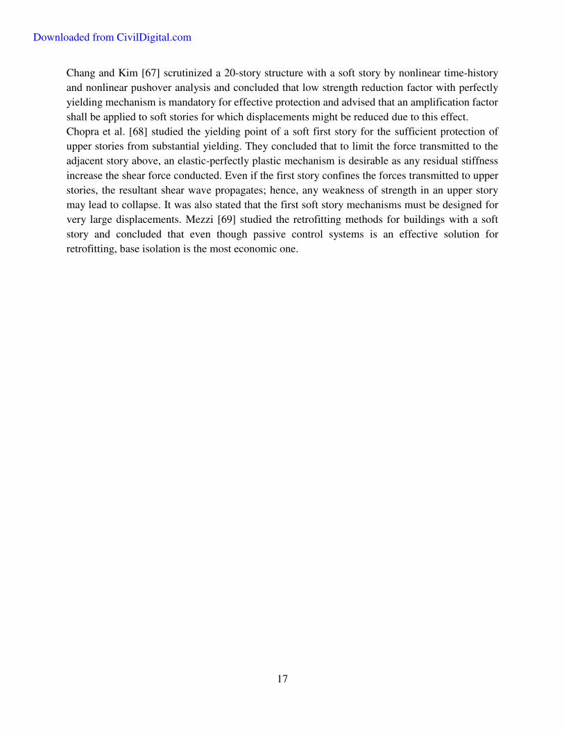
Chang and Kim [67] scrutinized a 20-story structure with a soft story by nonlinear time-history
and nonlinear pushover analysis and concluded that low strength reduction factor with perfectly
yielding mechanism is mandatory for effective protection and advised that an amplification factor
shall be applied to soft stories for which displacements might be reduced due to this effect.
Chopra et al. [68] studied the yielding point of a soft first story for the sufficient protection of
upper stories from substantial yielding. They concluded that to limit the force transmitted to the
adjacent story above, an elastic-perfectly plastic mechanism is desirable as any residual stiffness
increase the shear force conducted. Even if the first story confines the forces transmitted to upper
stories, the resultant shear wave propagates; hence, any weakness of strength in an upper story
may lead to collapse. It was also stated that the first soft story mechanisms must be designed for
very large displacements. Mezzi [69] studied the retrofitting methods for buildings with a soft
story and concluded that even though passive control systems is an effective solution for
retrofitting, base isolation is the most economic one.
Downloaded from CivilDigital.com
18
CHAPTER 3.
SOFT STORY IRREGULARITY
3.1 General
Irregularities in the building lead to unpredictable behavior of the structure during seismic ground
motions even if quality of construction is maintained or elements satisfy the requirements of the
code. The effects of irregularity cannot be accessed using conventional analysis methodologies. A
structure with vertical irregularity is found to be having non uniform drift demands. Moreover,
open ground storey structures are susceptible to concentrated ground story drifts due to very low
stiffness with respect to over lying stories. Current building codes emphasis on formation of plastic
hinges in the structural members especially due to the lateral loading in order to increase the energy
dissipation level of the structural system. Concentration of plastic hinges in definite locations
occurs due to irregularities in the structure during an earthquake, which is undesirable.
The vertical irregularities in building structures may be categorized as weak story, soft story,
discontinuity of vertical elements and mass irregularity. Depending on the soft story criteria in the
Indian codes, it is obvious that the mass irregularity is also considered within the soft story
irregularity definition. Although weak and soft story irregularities may cause analogous structural
damages in an earthquake, these two irregularity types are quite different in definition. A weak
story is defined by comparing effective shear areas of lateral force resisting systems of the adjacent
stories; on the other hand, the soft story irregularity is defined by relating the stiffness of the lateral
force resisting systems of adjacent stories. Basically the difference between the soft and weak story
irregularity can be explained by considering the difference in stiffness and strength. Moreover, the
changes in the element sizes will affect both. The behavior of the structures having soft stories has
been presented in the following section.
3.2 Soft Story Behavior
Structures having weak ground stories suffered major structural damage and collapsed in the recent
earthquakes. Large open spaces with less infill, exterior walls and higher floor heights at the
ground level result in soft ground story. In such structures, the stiffness of the lateral load resisting
systems at that level is quite less than the stories above or below, leading to high lateral
displacement in that floor. Lateral displacement diagram of a building with a soft ground story
under lateral loading is shown in Figure 1.
Downloaded from CivilDigital.com

19
Figure 2 Excessive drift in soft ground story under lateral loading
Non uniform lateral force occurs along the height of the structure during an earthquake if irregular
inter-story drifts take place between adjacent stories. This focuses lateral forces on the story (or
stories) having large displacement(s). Hence, if the ductility demands are not met in the design of
such building for that story and the inter-story drifts cannot be limited leading to a local failure
mechanism or even a story failure mechanism, which can lead to the collapse of the entire system,
arose due to the high level of load-deformation (P-Δ) effects. Figure 2 shows the collapse
mechanism of such a building structure with a soft ground story under both earthquake and gravity
loads.
Figure 3 Collapse mechanism of a building structure having a soft story
Downloaded from CivilDigital.com
20
Lateral drift of a story depends on stiffness, mass and lateral force distributed on that story. Also,
the lateral force distribution along the height of a structure is directly associated to mass and
stiffness of each story. If P-Δ effect is referred to be the main cause of dynamic collapse of building
during earthquakes, precisely determined lateral displacements from elastic design procedure can
provide very significant information regarding structural behavior of the system. Therefore
dynamic analysis technique is required in design codes for accurate distribution of the earthquake
forces along the building height, comprehending modal effects and local ductility demands
efficiently. Even though some of the current codes define a soft story irregularity in contrast of
stiffness between adjacent floors, displacement based criteria will be more appropriate for such
irregularity determination, since it can quantify the mass, stiffness and force distribution concepts.
Next section will elaborate the requirements in the design of building structures with a soft story
in Indian codes.
3.3 Indian Earthquake Code
As described earlier as per Indian code, the stiffness of a story should not be less than 60% of the
adjacent story above or should not be less than 70% of the average stiffness of the three stories
above. Additionally, the Indian Earthquake Code requires relative displacements in adjacent
stories to be greater than 1.3, in order to define the irregularity as a soft story.
The Indian Earthquake Code also suggests pushover analysis confirming to ATC-40 for the
determination of ductility demands. However, accepting that this method may not be very
appropriate, code suggests an amplification factor of 2.5, for amplifying the member forces, to be
used for the design of the soft story’s columns and beams. Then again, an amplification factor of
1.5 is suggested if symmetric shear walls are implemented in plan of such buildings.
Downloaded from CivilDigital.com
21
CHAPTER 4.
NONLINEAR PUSHOVER ANALYSIS
4.1 Introduction
In order to explore the nonlinear behavior of the building structures nonlinear static pushover are
performed on the analytical models. In this section, the nonlinear material properties used in this
study and the underlying principles on the nonlinear static pushover analysis methods is explained.
4.2 Nonlinear Behavior & Plastic Hinge formations in Structural Elements
The nonlinear performance of a structure depends on the nonlinear responses of the structural
elements that contribute to the lateral force resisting system. Therefore, it is necessary to describe
and evaluate nonlinear behavior of any such elements before applying nonlinear analysis method
on a structure.
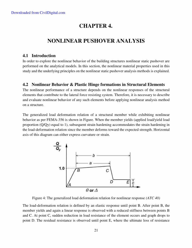
The generalized load deformation relation of a structural member while exhibiting nonlinear
behavior as per FEMA-356 is shown in Figure. When the member yields (applied load/yield load
proportion (Q/Qy) equal to 1), subsequent strain hardening accommodates the strain hardening in
the load-deformation relation since the member deforms toward the expected strength. Horizontal
axis of this diagram can either express curvature or strain.
Figure 4: The generalized load deformation relation for nonlinear response (ATC 40)
The load-deformation relation is defined by an elastic response until point B. After point B, the
member yields and again a linear response is observed with a reduced stiffness between points B
and C. At point C, sudden reduction in load resistance of the element occurs and graph drops to
point D. The residual resistance is observed until point E, where the ultimate loss of resistance
Downloaded from CivilDigital.com

22
takes place. The initial slope, between points A and B defines the elastic stiffness of the structure.
The second slope between points B and C is taken as 10% of the initial slope for analyses in the
study. Point C in this diagram signifies the ultimate strength of the element where the substantial
stiffness degradation begins. This nonlinear response of the structural member is called hinge
property which is defined symmetrically case of columns and beams in order to include the
reversals to the calculations. In order to model nonlinear response of an element, ATC-40 and
FEMA-356 express the parameters A, B and C in Figure by defining plastic rotation angles.
Figure 5: Acceptance criteria on a force versus deformation diagram (ATC 40)
Acceptance criteria are also defined in ATC-40 and FEMA-356 codes depending on the plastic
hinge rotations by considering various performance levels. In Figure 5 the acceptance criteria on
a force versus deformation diagram are given. In this diagram, points marked as IO, LS and CP
represent immediate occupancy, life safety and collapse prevention, respectively.
Downloaded from CivilDigital.com

23
4.3 Analysis
Nonlinear static pushover analysis has become most commonly used technique to interpret the
nonlinear behavior of the structures in the recent years. In simplified procedure, a capacity curve
is achieved which depicts the relation of base shear and roof displacement. The curve also
represents the performance of the building structure under increasing base shear forces. As the
capacities of the members of the lateral force resisting system surpass their yield limits during the
increasing of the base shear forces, slope of the force-deformation curve will alter, and hence the
nonlinear behavior can be represented.
Figure 6 : A pushover curve of a building structure (ATC 40)
Depending on the initial load pattern, in the analysis, applied lateral forces to a model are increased
in a consistent manner. Member forces are obtained for each step. In the next step of the analysis
stiffness of the members are changed when capacity is exceeded, according to the hinge properties.
This progression ends when the structure becomes unstable. Figure shows a typical pushover
curve. Pushover analysis can either be performed considering the control over the force or the
displacement. Force control option is beneficial when the magnitude of the load is known clearly,
and the structure is predicted to support that load. The displacement control is useful when the
extent of the load is unknown and displacements are investigated.
SAP2000, computer software is utilized in the study, due to its simplicity and its computation
power to carry out the pushover analyses. Following steps are performed in the pushover analysis
of a structure in SAP2000:
The model representing the structure is generated and vertical loads (dead load and live
load); member properties and member nonlinear behaviors are defined and assigned to the
model.
Hinge properties are defined and are assigned to the member ends considering end-offsets.
Downloaded from CivilDigital.com

24
Lateral load patterns to be used in the pushover analyses are assigned.
Force controlled pushover loading is used initially for the lateral load increment analyses,
applied to the model as a pushover case. Initial pushover load case is comprises of the dead
loads and reduced live loads.
Now a new displacement controlled pushover case is assigned considering the lateral load
pattern which was used above for the incremental pushover analysis, starting from the
initial pushover case.
In this study, the hinge properties are determined according to ATC-40 and FEMA-356 for beams
and columns. The tabulated forms of the moment-rotation relationships of the hinges at the beams
and at the columns that are used in the analytical models are given in Table.
Downloaded from CivilDigital.com

25
CHAPTER 5.
EQUIVALENT BRACED FRAME METHOD In order to model structures with infilled walls, equivalent diagonal strut approach for analysis and
design of infilled frames has been adopted. The method considers the inelastic and plastic behavior
of infilled frames bearing in mind the limited ductility of infilled materials. It offers a rational basis
for assessing the lateral strength and stiffness of the infilled frames and infill diagonal cracking
load. Analytical macro-model was used which is based on equivalent strut approach, combined
with a smooth hysteretic model to replicate masonry infills in nonlinear analyses (monotonic
pushover analysis). The envelope properties of the strut such as stiffness and the control points of
force-deformation relations was obtained from mechanics of infill-frame interaction proposed by
Saneinejad [70].
Figure 7 : Equivalent Strut Model (a) Masonry Infill Panel (b) Strength Envelope of Masonry Panel
Monotonic lateral force-deformation relation is bilinear curves having an initial elastic stiffness
until the yield force, Vy, and post-yield degraded stiffness till the maximum force, Vm. The
maximum lateral force, Vm, and the corresponding displacement, um, in the infill masonry panel.
Downloaded from CivilDigital.com

26
'
'
'
'
'
cos
1 0.45 tan
1.25
cos
d m
s
m
m d
A f
tl
VMPa tl
L
1
'
cosm d
m
Lu
2
Where,
t = the thickness or out of plane dimension of the infill panel
= 1tan /h l
'mf = masonry prism strength
'm = corresponding strain
s = shear strength or cohesion of masonry
The area, dA , and the length, dL , of the equivalent diagonal strut were obtained from :
' ' '1 0.5
cos cos
c b ac c b
c c cd
fth tl th
f f fA
3
2 '2 '21d cL h l
4
Where the quantities c , b , c , b , af and cf depend on the geometric and material properties of
the frame and the infill panel.
c = Upper bound or failure normal contact stresses at the column-infill interface
cf = the compressive strength of the masonry
af = compressive stress of infill in its central region
b = contact shear stresses at the beam-infill interface
Downloaded from CivilDigital.com
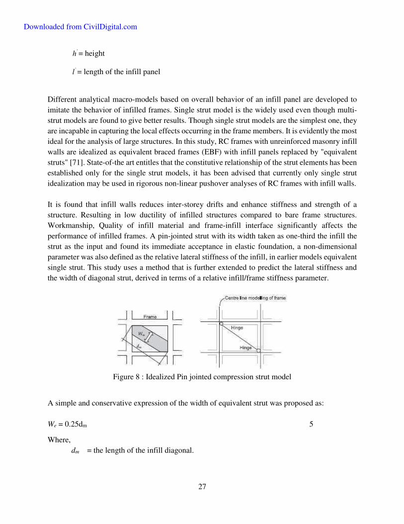
27
'h = height
'l = length of the infill panel
Different analytical macro-models based on overall behavior of an infill panel are developed to
imitate the behavior of infilled frames. Single strut model is the widely used even though multi-
strut models are found to give better results. Though single strut models are the simplest one, they
are incapable in capturing the local effects occurring in the frame members. It is evidently the most
ideal for the analysis of large structures. In this study, RC frames with unreinforced masonry infill
walls are idealized as equivalent braced frames (EBF) with infill panels replaced by "equivalent
struts" [71]. State-of-the art entitles that the constitutive relationship of the strut elements has been
established only for the single strut models, it has been advised that currently only single strut
idealization may be used in rigorous non-linear pushover analyses of RC frames with infill walls.
It is found that infill walls reduces inter-storey drifts and enhance stiffness and strength of a
structure. Resulting in low ductility of infilled structures compared to bare frame structures.
Workmanship, Quality of infill material and frame-infill interface significantly affects the
performance of infilled frames. A pin-jointed strut with its width taken as one-third the infill the
strut as the input and found its immediate acceptance in elastic foundation, a non-dimensional
parameter was also defined as the relative lateral stiffness of the infill, in earlier models equivalent
single strut. This study uses a method that is further extended to predict the lateral stiffness and
the width of diagonal strut, derived in terms of a relative infill/frame stiffness parameter.
Figure 8 : Idealized Pin jointed compression strut model
A simple and conservative expression of the width of equivalent strut was proposed as:
We = 0.25dm 5
Where,
dm = the length of the infill diagonal.
Downloaded from CivilDigital.com

28
Figure 9: Compressive stress-strain curves for masonry
Downloaded from CivilDigital.com
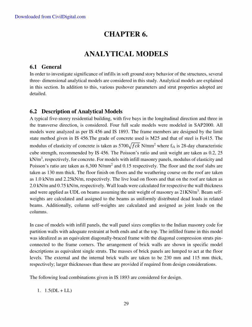
29
CHAPTER 6.
ANALYTICAL MODELS
6.1 General
In order to investigate significance of infills in soft ground story behavior of the structures, several
three- dimensional analytical models are considered in this study. Analytical models are explained
in this section. In addition to this, various pushover parameters and strut properties adopted are
detailed.
6.2 Description of Analytical Models
A typical five-storey residential building, with five bays in the longitudinal direction and three in
the transverse direction, is considered. Four full scale models were modeled in SAP2000. All
models were analyzed as per IS 456 and IS 1893. The frame members are designed by the limit
state method given in IS 456.The grade of concrete used is M25 and that of steel is Fe415. The
modulus of elasticity of concrete is taken as 5700√𝑓𝑐𝑘 N/mm2 where fck is 28-day characteristic
cube strength, recommended by IS 456. The Poisson’s ratio and unit weight are taken as 0.2, 25
kN/m3, respectively, for concrete. For models with infill masonry panels, modulus of elasticity and
Poisson’s ratio are taken as 6,300 N/mm2 and 0.15 respectively. The floor and the roof slabs are
taken as 130 mm thick. The floor finish on floors and the weathering course on the roof are taken
as 1.0 kN/m and 2.25kN/m, respectively. The live load on floors and that on the roof are taken as
2.0 kN/m and 0.75 kN/m, respectively. Wall loads were calculated for respective the wall thickness
and were applied as UDL on beams assuming the unit weight of masonry as 21KN/m3. Beam self-
weights are calculated and assigned to the beams as uniformly distributed dead loads in related
beams. Additionally, column self-weights are calculated and assigned as joint loads on the
columns.
In case of models with infill panels, the wall panel sizes complies to the Indian masonry code for
partition walls with adequate restraint at both ends and at the top. The infilled frame in this model
was idealized as an equivalent diagonally-braced frame with the diagonal compression struts pin-
connected to the frame corners. The arrangement of brick walls are shown in specific model
descriptions as equivalent single struts. The masses of brick panels are lumped to act at the floor
levels. The external and the internal brick walls are taken to be 230 mm and 115 mm thick,
respectively; larger thicknesses than these are provided if required from design considerations.
The following load combinations given in IS 1893 are considered for design.
1. 1.5(DL + LL)
Downloaded from CivilDigital.com

30
2. 1.2(DL + LL* + ELx)
3. 1.2(DL + LL* +ELy)
4. 1.5(DL ± ELx)
5. 1.5(DL ± ELy)
6. 0.9DL ± 1.5ELx
7. 0.9DL+ 1.5Ely
Where, LL equals 25 percent of the full design live load LL on the floors and is zero on the roof.
When the earthquake load is considered, the seismic weight is obtained by considering 25 percent
of LL. The total design base shear, Vb , on the building is calculated as per the IS 1893, and given
by
Vb = AhW, 6
Where, W is the seismic weight of the whole building and Ah the design horizontal acceleration
spectrum given by
2a
h
SZIA
R g
7
Where,
Z = the seismic zone factor taken as 0.36 for seismic zone V
I = the importance factor taken as 1.0 for the ordinary residential building
2R = the response reduction factor taken as
6.0 for the ordinary RC MRFs detailed as per IS 456 and as
10.0 for special RC MRFs detailed as per the Indian seismic detailing code.
aS
g = the average response acceleration coefficient
The fundamental natural period, T, (seconds) of the bare and infilled frames are calculated using
the empirical expressions given in IS 1893.
0.09if
hT
d
8
Where,
Downloaded from CivilDigital.com
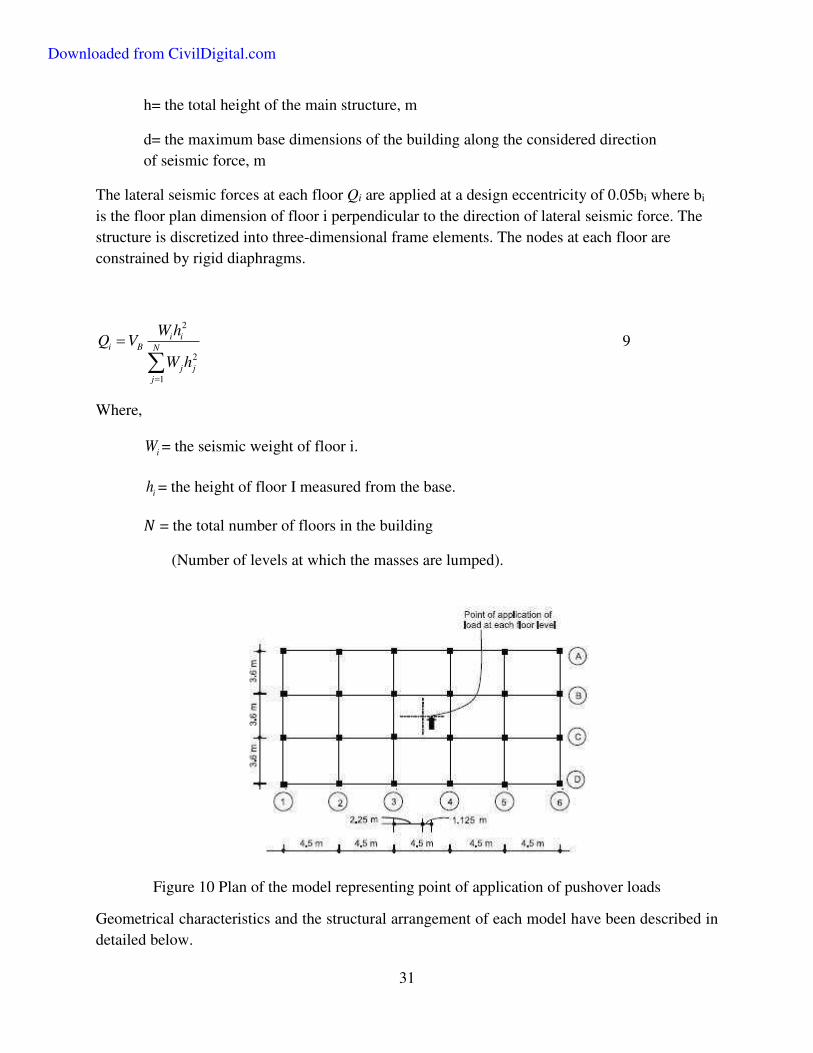
31
h= the total height of the main structure, m
d= the maximum base dimensions of the building along the considered direction
of seismic force, m
The lateral seismic forces at each floor Qi are applied at a design eccentricity of 0.05bi where bi
is the floor plan dimension of floor i perpendicular to the direction of lateral seismic force. The
structure is discretized into three-dimensional frame elements. The nodes at each floor are
constrained by rigid diaphragms.
2
2
1
i ii B N
j j
j
W hQ V
W h
9
Where,
iW = the seismic weight of floor i.
ih = the height of floor I measured from the base.
𝑁 = the total number of floors in the building
(Number of levels at which the masses are lumped).
Figure 10 Plan of the model representing point of application of pushover loads
Geometrical characteristics and the structural arrangement of each model have been described in
detailed below.
Downloaded from CivilDigital.com

32
Model 1 – Bare Frame Model
This model was designed bare frame force and moment which is currently practiced in India. The
wall loads are applied as UDLs on the beam elements.
Figure 11 : Bare frame model
The member reinforcements are calculated by this software and the other displacement
requirements, which are defined in the IS 456, are taken into account.
Downloaded from CivilDigital.com
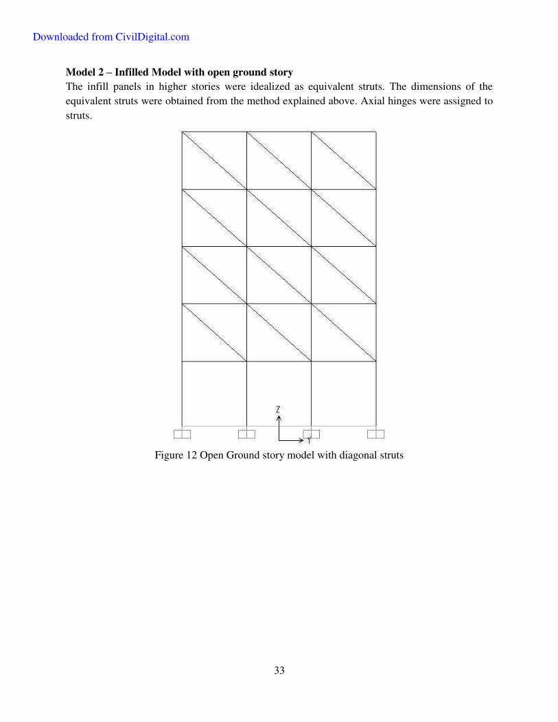
33
Model 2 – Infilled Model with open ground story
The infill panels in higher stories were idealized as equivalent struts. The dimensions of the
equivalent struts were obtained from the method explained above. Axial hinges were assigned to
struts.
Figure 12 Open Ground story model with diagonal struts
Downloaded from CivilDigital.com
34
Model 3 – Fully infilled Model
The model was designed considering axial forces in columns and beams by resolving forces from
the equivalent struts. Hinge definitions are calculated and assigned as in model 2.
Figure 13 : Fully infilled structure with equivalent single struts
Downloaded from CivilDigital.com

35
6.3 Modeling of Plastic Hinges
6.3.1 RCC Frame Members
After obtaining the dimensions and the reinforcements of the members, nonlinear hinge properties
are calculated and matched with the SAP2000’s default hinge properties.
6.3.1.1 Plastic Hinge Length
The plastic hinges in members are assumed to form at a distance equal to half the average plastic
hinge length, lp, where lp is given by Baker’s formula
1 30.8p
zl k k c
d
10
Where,
z =distance of critical section to the point of contraflexure
d = effective depth of the member
c = neutral axis depth at ultimate moment
1k = 0.7(for mild steel)
3k = 0.9(for cold-worked steel)
'3
0.6
0.6 0.0128 11.7
0.9
ck f
11
Where,
'cf = 0.8 times the cube strength
The axial force vs. moment interaction diagram must be calculated and plotted in order to
determine nonlinear hinge properties of a column. The column exhibits nonlinear behavior when
an axial force and corresponding moment value of loading is formed outside plotted interaction
diagram.
Downloaded from CivilDigital.com

36
Figure 14 : Idealized M-θ Curves for Hinge Definitions
For determining the nonlinear hinge properties of a beam, the moment capacity values must be
calculated. When the moment value at that beam exceeds the calculated capacity moment, this
beam exhibits nonlinear behavior.
Figure 15: Idealized P-M interaction curve for columns
The moment-curvature (M- Φ) curves of columns are calculated for axial load corresponding to full DL and 25% Live Load. These curves are idealized as bilinear curves using initial tangent and
ultimate moment. The bending moment diagram of a member under lateral forces varies linearly.
The moment-rotation (M− θ) relationship for this distribution of moments is obtained using the
M- Φ relationship. A fixed-end member can be replaced by an equivalent cantilever member of
half span, with a concentrated load at its tip, Fig 3, if the point of contraflexure is at the midspan.
The yield and ultimate rotations θy and θu respectively, are obtained by the following relations:
2
4
y
y
LM
EI
12
u y p u yl
13
Where,
Downloaded from CivilDigital.com

37
L , E and I = length, modulus of elasticity and moment of inertia of the member
respectively
u & y = idealized ultimate and yield curvatures of the section respectively
pl = length of the plastic hinge
Figure 16: P-M Interaction curve of RC column
Table 1 : Moment – Rotation values used for defining Plastic Hinges
Downloaded from CivilDigital.com
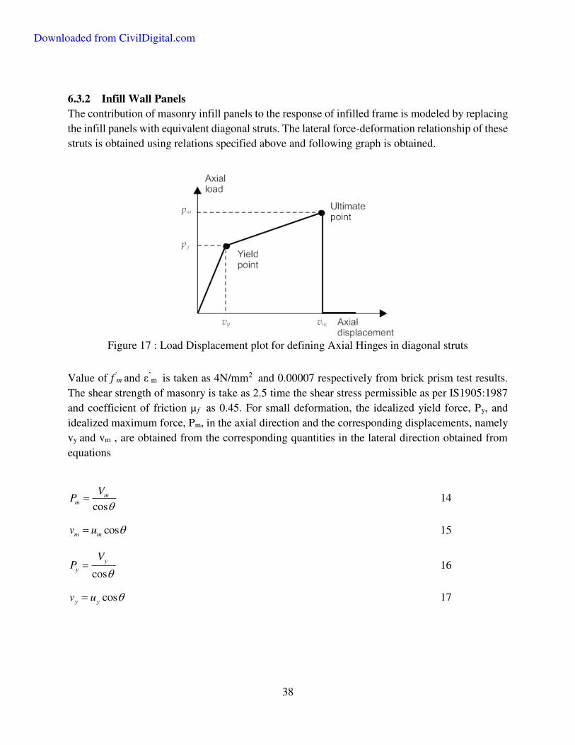
38
6.3.2 Infill Wall Panels
The contribution of masonry infill panels to the response of infilled frame is modeled by replacing
the infill panels with equivalent diagonal struts. The lateral force-deformation relationship of these
struts is obtained using relations specified above and following graph is obtained.
Figure 17 : Load Displacement plot for defining Axial Hinges in diagonal struts
Value of f’m and ε’
m is taken as 4N/mm2 and 0.00007 respectively from brick prism test results.
The shear strength of masonry is take as 2.5 time the shear stress permissible as per IS1905:1987
and coefficient of friction µ f as 0.45. For small deformation, the idealized yield force, Py, and
idealized maximum force, Pm, in the axial direction and the corresponding displacements, namely
vy and vm , are obtained from the corresponding quantities in the lateral direction obtained from
equations
cosm
m
VP
14
cosm mv u 15
cosy
y
VP
16
cosy yv u
17
Downloaded from CivilDigital.com

39
Figure 18: Calculation of lateral strength of masonry-infill walls
The figure below demonstrates assigned hinge locations when infill panels are replace by
equivalent strut members. In case of bare frames P M hinges are assigned to columns and moment
hinges are assigned to beam members.
Figure 19 : Plastic Hinge Assignments
The geometrical properties of the model are indicated in the figure. The size and reinforcement
details changes as the model changes.
Downloaded from CivilDigital.com

40
Figure 20 : Section Assignments
Downloaded from CivilDigital.com

41
CHAPTER 7.
RESULTS AND DISCUSSIONS
7.1 Bare Frame
The present analysis and design philosophies can be represented by the bare frame model, which
neglects the effects and contribution of infill panels in the building, thereby ignoring their stiffness
and strength contributions. Figure shows the pushover curve for the model.
The pushover obtained by the pushover analysis of the frame is shown in Figure 21. Performance
was observed to be Linear in different members of the frame up to a base shear of about 10%
seismic weight and up to a top floor displacement corresponding to 0.33% drift ratio. Nonlinearity
was observed to be well scattered along the height of the frame and failure of frame was found to
take place due to the flexural failure of first story columns at the ultimate lateral load corresponding
to 17% seismic weight and lateral drift of 1%.
Figure 21 : Pushover curve for Model 1
Downloaded from CivilDigital.com

42
Figure 22 : Hinge formation pattern at Ultimate load.
Failure of the first-story columns (Figure 22) was observed because the frame was designed as a
weak column-strong beam frame system to reflect the current design practice adopted by designers
in India as well as in many other countries.
7.2 Open First-Story Frame
In this model, stiffness and contribution of masonry infills were taken into account in the upper
stories; frames in the first story were kept open, without diagonal struts.
Downloaded from CivilDigital.com
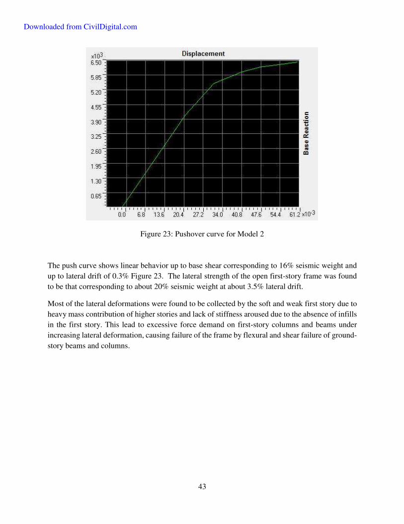
43
Figure 23: Pushover curve for Model 2
The push curve shows linear behavior up to base shear corresponding to 16% seismic weight and
up to lateral drift of 0.3% Figure 23. The lateral strength of the open first-story frame was found
to be that corresponding to about 20% seismic weight at about 3.5% lateral drift.
Most of the lateral deformations were found to be collected by the soft and weak first story due to
heavy mass contribution of higher stories and lack of stiffness aroused due to the absence of infills
in the first story. This lead to excessive force demand on first-story columns and beams under
increasing lateral deformation, causing failure of the frame by flexural and shear failure of ground-
story beams and columns.
Downloaded from CivilDigital.com
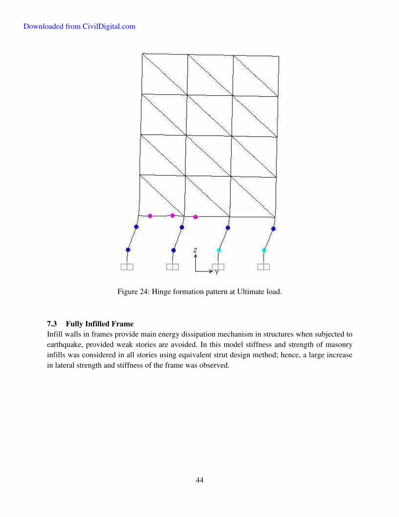
44
Figure 24: Hinge formation pattern at Ultimate load.
7.3 Fully Infilled Frame
Infill walls in frames provide main energy dissipation mechanism in structures when subjected to
earthquake, provided weak stories are avoided. In this model stiffness and strength of masonry
infills was considered in all stories using equivalent strut design method; hence, a large increase
in lateral strength and stiffness of the frame was observed.
Downloaded from CivilDigital.com

45
Figure 25: Pushover curve for Model 3
However, the lateral strength of the frame reduced drastically after failure of infills in the ground
story. A significant variation was observed in the capacity curves when different mortar grades
were used in masonry.
First, inelastic activity was observed at a very high lateral load corresponding to 35% seismic
weight; however, the corresponding drift level was only 0.06%, indicating a very strong and stiff
system. The failure of some of the first-story infills took place at a base shear corresponding to
44% seismic weight and only 0.3% drift, and therefore, a large drop was observed in lateral
strength. This indicates the brittleness associated with the fully infilled frame systems. After the
failure of a significant amount of infill walls in the frame, lateral load behavior was observed to
be quite similar to that of the bare frame. It was noted that the presence of infills in the first story
prevents premature failure of first story columns.
Downloaded from CivilDigital.com
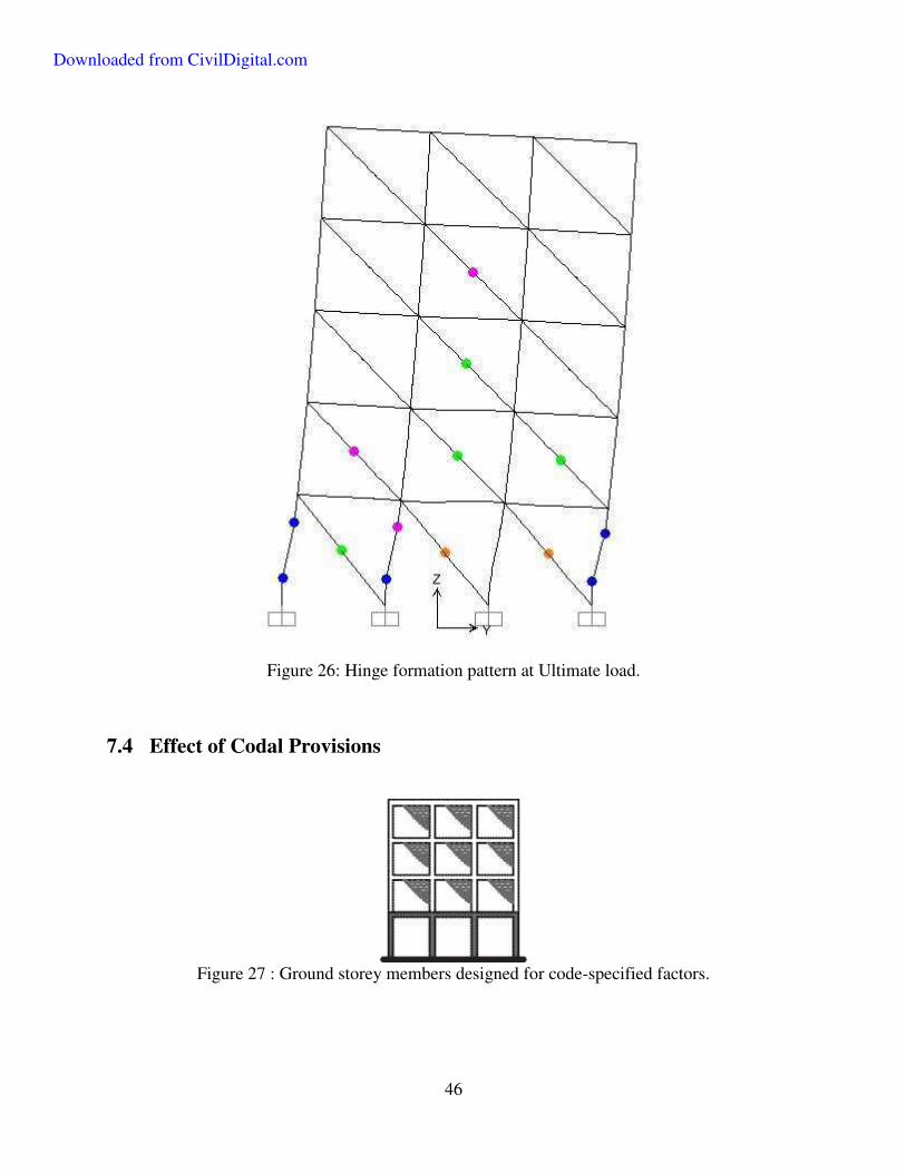
46
Figure 26: Hinge formation pattern at Ultimate load.
7.4 Effect of Codal Provisions
Figure 27 : Ground storey members designed for code-specified factors.
Downloaded from CivilDigital.com

47
Indian seismic code advices that the members of the open ground story are to be designed for 2.5
times design seismic forces. The efficiency of these strengthening provisions, in which the lateral
strength of the columns and beams of the open ground story required to be increased using
predetermined multiplying factors, was evaluated considering a multiplying factor of 2.5.
Reinforcement details and plastic hinge properties were improved for sections.
Figure 28: Pushover curve for Strengthened Model
Elastic behavior was observed up to a base shear corresponding to about 40% of seismic weight
and 0.15% drift. The lateral strength of the frame was found to increase significantly to about 50%
seismic weights; however, corresponding lateral drift reduced to only 1.6%. The collapse
mechanism of the strengthened frame did not alter when compared with the non-strengthened open
first story frame. Plastic hinges were observed to be concentrated in only first-story columns due
to their increased stiffness and the frame failed by flexural failure of these columns. Plastic hinges
were not observed in first-story beams; therefore, it is necessary to ascertain if there is any
advantage to increasing the design forces for open first-story beams.
Downloaded from CivilDigital.com
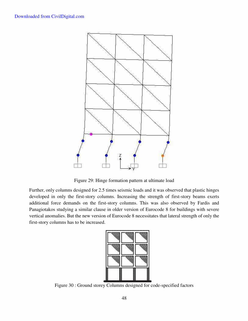
48
Figure 29: Hinge formation pattern at ultimate load
Further, only columns designed for 2.5 times seismic loads and it was observed that plastic hinges
developed in only the first-story columns. Increasing the strength of first-story beams exerts
additional force demands on the first-story columns. This was also observed by Fardis and
Panagiotakos studying a similar clause in older version of Eurocode 8 for buildings with severe
vertical anomalies. But the new version of Eurocode 8 necessitates that lateral strength of only the
first-story columns has to be increased.
Figure 30 : Ground storey Columns designed for code-specified factors
Downloaded from CivilDigital.com
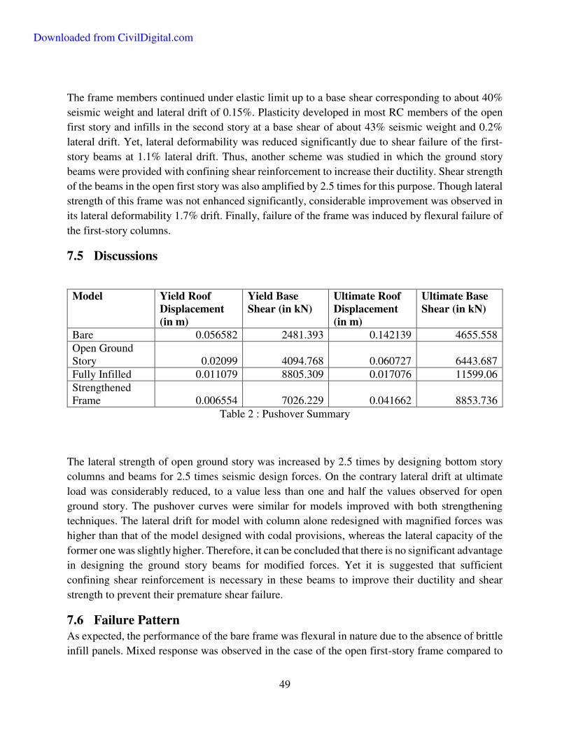
49
The frame members continued under elastic limit up to a base shear corresponding to about 40%
seismic weight and lateral drift of 0.15%. Plasticity developed in most RC members of the open
first story and infills in the second story at a base shear of about 43% seismic weight and 0.2%
lateral drift. Yet, lateral deformability was reduced significantly due to shear failure of the first-
story beams at 1.1% lateral drift. Thus, another scheme was studied in which the ground story
beams were provided with confining shear reinforcement to increase their ductility. Shear strength
of the beams in the open first story was also amplified by 2.5 times for this purpose. Though lateral
strength of this frame was not enhanced significantly, considerable improvement was observed in
its lateral deformability 1.7% drift. Finally, failure of the frame was induced by flexural failure of
the first-story columns.
7.5 Discussions
Model Yield Roof
Displacement
(in m)
Yield Base
Shear (in kN)
Ultimate Roof
Displacement
(in m)
Ultimate Base
Shear (in kN)
Bare 0.056582 2481.393 0.142139 4655.558 Open Ground Story 0.02099 4094.768 0.060727 6443.687 Fully Infilled 0.011079 8805.309 0.017076 11599.06 Strengthened Frame 0.006554 7026.229 0.041662 8853.736
Table 2 : Pushover Summary
The lateral strength of open ground story was increased by 2.5 times by designing bottom story
columns and beams for 2.5 times seismic design forces. On the contrary lateral drift at ultimate
load was considerably reduced, to a value less than one and half the values observed for open
ground story. The pushover curves were similar for models improved with both strengthening
techniques. The lateral drift for model with column alone redesigned with magnified forces was
higher than that of the model designed with codal provisions, whereas the lateral capacity of the
former one was slightly higher. Therefore, it can be concluded that there is no significant advantage
in designing the ground story beams for modified forces. Yet it is suggested that sufficient
confining shear reinforcement is necessary in these beams to improve their ductility and shear
strength to prevent their premature shear failure.
7.6 Failure Pattern
As expected, the performance of the bare frame was flexural in nature due to the absence of brittle
infill panels. Mixed response was observed in the case of the open first-story frame compared to
Downloaded from CivilDigital.com
50
bare frames, failure took place due to failure of RC members in flexural and shear. Lateral load
carrying capacity of fully infilled frame was found to decrease drastically after the failure of
masonry infills in the first and higher stories, followed by the lateral load behavior of a bare frame.
In strengthened frames using codal method, nonlinearity was found to be focused in the first-story
columns due to increased stiffness, were failure of the frame took place by flexural failure of the
first-story columns.
When only first-story columns were designed for magnified forces, failure took place at a very low
lateral drift by shear failure of first-story beam, when the first-story beams were provided with
normal shear reinforcement. It was noticed that when sufficient confining shear reinforcement was
provided in these beams, flexural failure of first-story columns took place at significantly higher
lateral deformation. In comparison to codal models, plasticity was observed to be dispersed also
in the second story of the frame as well in modified code model.
7.7 Summary and Conclusions
In the present study, acceptability and adoptability of open ground story structures along with
current analysis and design practices in India was studied. The effectiveness of several
strengthening schemes in improving the performance of open first-story RC frames was evaluated
using pushover analyses of typical 3D frame models.
The strengthening schemes recommended in IS1893-2002 were found to be ineffective in
improving the lateral deformability of such structures exploiting predetermined multiplying factors
for increasing the lateral strength. Additionally, it was concluded that beams in the open first story
are not required to be designed for higher seismic forces. However, sufficient confining
reinforcement is to be provided in these beams to improve their ductility and shear strength. Even
though the lateral strength of the open ground story buildings are comparatively improved by codal
methods the overall ductility and deformation capacity of the building is reduced.
An abrupt reduction in lateral strength was observed in fully infilled structures immediately after
the failure of first story infills. Hence, the ductility of these frames was found to be significantly
lower. Infill panels improve the energy dissipation and global stiffness of the building, thereby
improving the comparative performance during severe earthquakes. The drift and the strength
demands in the ground storey columns are very large for structures with soft ground storeys. It
may not be easy to provide such capacities in the columns of the first storey. Hence, it is clear that
such structures will exhibit poor performance during a strong shaking.
Major conclusions of the present study are:
Performance of open ground story under lateral loadings, especially ductility of RC frames
cannot be improved by using codal strengthening provisions, by designing the ground-story
members for magnified forces.
Downloaded from CivilDigital.com

51
It was found that the current analysis practice of idealizing such as bare frame structures
overestimates the ductility and drift performance during design earthquakes.
Open first story structures with concentrated vertical irregularity are least advised in
seismically active regions due its susceptibility to failure under severe earthquakes and lack
of adequate energy dissipation efficiency, which has been proved in past earth quakes.
Appropriate strengthening systems are to be designed and tested for such buildings for
which further research is necessary.
Downloaded from CivilDigital.com

52
CHAPTER 8.
REFERENCES
[1] AIJ, "Preliminary Reconnaissance Report of the 1995 Hyogoken-Nanbu Earthquake,"
Architectural Institute of Japan, Tokyo, Japan. , 1995.
[2] EQEI, "The January 17, 1994 Northridge, California Earthquake - An EQE Report,," EQE
International, San Francisco, USA, 1994.
[3] J. L. W. ,. N. T. L. E. F. G. Ari Wibowo, "Collapse modelling analysis of a precast soft
storey building in Australia," Elsevier Ltd., 2010.
[4] S. K. J. a. C. M. Jaswant N. Arlekar, "Seismic Response of RC Frame Buildings with Soft
First Storeys," 1997.
[5] M. N. a. P. T. B. Fardis, "Seismic design and response of bare and masonry-infilled
reinforced concrete buildings.Part II: Infilled structures.”," vol. 475–503., 1997.
[6] M. S. B. Nollet, "Stiffened-Story Wall-Frame Tall Building Structure," Vols. Computers
and Structure, Vol. 66, No. 2-3,, 1998.
[7] S. V. Polyakov, "On the interactions between masonry filler walls and enclosing frame
when loaded in the plane of the wall," 1956.
[8] B. a. B. Prasad, "The Influence of Masonry Infill In Reinforced Concrete Multi-Story
Buildings to Near-Fault Ground Motions," 2006.
[9] H. M. a. T. Kabeyasawa, "Effect of Infill Masonry Walls on the Seismic Responseof
Reinforced Concrete Buildings Subjected to the , Bam Earthquake Strong Motion :A Case
Study of Bam Telephone Center," 2004.
[10] X. Y. a. J. M. W. B. Tso-Chien Pan, "Effects of infill walls and floor diaphragms on the
dynamic characteristics of a narrow-rectangle building," 2006.
[11] D. C. R. K. J. Hemant B. Kaushik, "Code Approaches to Seismic Design of Masonry-
Infilled Reinforced Concrete Frames: A State-of-the-Art Review," vol. Volume 22, 2006.
Downloaded from CivilDigital.com
53
[12] I. N. D. a. E. N. Mitsopoulou, "The deficiency of the macromodels with fixed support
interface conditions in the analytical modelling of infill panels," 1995.
[13] D. K. P. a. V. V. S. H. Singh, "Inelastic dynamic response of reinforced concrete infilled
frames," vol. 62, 1998.
[14] I. N. Doudoumis, "Finite technique modelling and investigation of the behaviour of elastic
infilled frames under monotonic loading," 2006.
[15] H. A. a. D. Moghaddam, "The State of the Art in Infilled Frames," 1987.
[16] A. B. Mehrabi, "Behavior of Masonry Infilled Reinforced Concrete Frames Subjected to
Lateral Loadings," University of Colorado, 1994.
[17] L. D. D. A. F. M. Silvia BRUNO, "SEISMIC PERFORMANCE OF PRE-CODE
REINFORCED CONCRETE BUILDINGS," 2000.
[18] B. D.K. Bell, "Evaluation of Earthquake Risk Buildings with Masonry Infill Panels," 2001.
[19] M. N. Fardis, "Experimental and Numerical Investigation on the seismic Response of R.C
Infilled frames and Recommendations for code Provisions," European Consortium of
Earthquake Shaking Tables and Prenormative Research in Support of Eurocode 8, 1996.
[20] P. N. a. A. Colombo, "Irregularities induced by nonstructural masonry panels in framed
buildings",," vol. 19, 1997.
[21] G. Al-Chaar, "Non-ductile behavior of reinforced concrete frames with masonry infill
panels subjected to in-plane loading.’’," 1998.
[22] M. D. a. P. Fajfar, "The effect of masonry infills on the seismic response of a four-storey
reinforced concrete frame -- a deterministic assessment," vol. 30, 2008.
[23] T. a. P. Paulay, "Seismic Design of Reinforced Concrete and Masonry Buildings," 1992.
[24] K. M. A. a. H. Kramul, "A rationale for determining the natural period of RC building
frames having infill," 2006.
[25] M. M. Kose, "Parameters affecting the fundamental period of RC buildings with infill
walls," vol. 31, 2008.
[26] M. P. G. Asteris, "Lateral Stiffness of Brick Masonry Infilled Plane Frames," 2003.
Downloaded from CivilDigital.com
54
[27] M. I. S. S. Ghassan Al-Chaar, "Behavior of Masonry-Infilled Nonductile Reinforced
Concrete Frames," 2002.
[28] M. C. &. J. S.K., "Beneficial influence of masonry infill walls on seismic performance of
RC frame buildings.," 2000.
[29] G.-W. M. ,. Y. L. Hong Hao, "Damage assessment of masonry infilled RC frames
subjected to blasting induced ground excitations," 2002.
[30] J. D. a. D. Thambiratnam, "Modelling and Analysis of Infilled Frame Structures Under
Seismic Loads," School of Urban Development, Queensland University of Technology,
2009.
[31] J. S. Liang Su, "Displacement-based earthquake loss assessment methodology for RC
frames infilled with masonry panels," Elsevier Ltd., 2012.
[32] T. C. Liauw, "An approximate method of analysis for infilled frames with or without
opening,," 1972.
[33] A. E. S. M. A. Fiorato, "An investigation of the interaction of reinforced concrete frames
with masonry walls.," 1970.
[34] B. S. S. A. H. KHAN, "A Simple Method of Analysis for Deflection and Stresses in Wall-
Frame Structures," 1976.
[35] P. B. S. Armin B. Mehrabi, "Finite Element Modelling of Masonry Infilled RC Frames,"
1997.
[36] P. a. S. M. A. Gulan, "Procedure for determining seismic vulnerability of building
structures.," 1999.
[37] A. J. a. L. Durrani, "Seismic Retrofit of Flat-Slab Buildings with Masonry Infills," 1994.
[38] G. L. G. E. a. A. Al-Chaar, "Effects of openings on structural performance of unreinforced
masonry infilled frames," 2003.
[39] M. Holmes, "Steel frames with brickwork and concrete infilling," 1961.
[40] A. T. Council, "ATC 40,Seismic Evaluation and Retrofit of Concrete Buildings," 1996.
[41] F. E. M. Agency, "Prestandard and Commentary for the Rehabilitation of Buildings,"
FEMA 356,, 2000.
Downloaded from CivilDigital.com

55
[42] P. a. F. M. Fajfar, "Nonlinear Seismic Analysis of R/C Buildings," European Earthquake
Engineering, 1997.
[43] E. M. a. S. M.A, "Behavior-Based Method to Determine Design Shear in Earthquake
Resistant Walls,," Journal of the Structural Division, American Society of Civil Engineers,
Vols. Vol.119, No.2, 1992.
[44] P. H. a. E. T, "Direct Inelastic Earthquake Design Using Secant Stiffness," ANCER
Networking of Young Earthquake Engineering Researchers and Professionals, 2004.
[45] M. A.S., "A Pushover Procedure for Tall Buildings," 12th European Conference on
Earthquake Engineering, 2002.
[46] F. S. a. P. T. Sasaki F., "Multi-Mode Pushover Procedure-A Method to Identify the Effect
of Higher Modes in a Pushover Analysis Proc," 6th U.S. National Conference on
Earthquake Engineering, Seattle, , 1998..
[47] C. A. a. G. R.K, "Modal Pushover Analysis Procedure to Estimate Seismic Demands for
Buildings: Theory and Preliminary Evaluation," National Science Foundation;U.S.-Japan
Cooperative Research in Urban Earthquake Disaster Mitigation, 2001.
[48] C. C. a. C. A.K, "Evaluation of Modal Pushover Analysis Using Generic Frames,,"
Earthquake Engineering and Structural Dynamics, 2003.
[49] A. T. a. F. A, "Modeling of Higher-Mode Effects Using an Optimal Multi-Modal Pushover
Analysis,," Earthquake Resistant Engineering Structures, 2005.
[50] C. A. a. G. R.K, "Role of Higher-"Mode" Pushover Analyses in Seismic Analysis of
Buildings,," Earthquake Spectra, , vol. Vol.21 No.4, 2005.
[51] G. B. a. K. K, "Adaptive Spectra Based Pushover Procedure for Seismic Evaluation of
Structures," Earthquake Spectra, 2000.
[52] L. M. a. K. Y. Jan T.S., "An Upper-Bound Pushover Analysis Procedure for Estimating the
Seismic Demands of High-Rise Buildings,," Engineering Structures 26, 2004.
[53] K. E. a. K. S, "Assessment of Current Nonlinear Static Procedures for Seismic Evaluation
of Buildings," Engineering Structures, 2007.
[54] M. A. a. E. A.S., "Static Pushover versus Dynamic Analysis of R/C Buildings,,"
Engineering Structures,, 2001.
Downloaded from CivilDigital.com

56
[55] K. H. a. S. K, "Pros and Cons of a Pushover Analysis of Seismic Performance Evaluation,,"
Engineering Structures, 1998.
[56] T. T. a. A. M. Inel M., "The Significance of Lateral Load Pattern in Pushover Analysis,,"
2003.
[57] S. A. a. A. B. Korkmaz A., "An Evaluation of Pushover Analysis for Various Load
Distributions," in 5th National Conference on Earthquake Engineering, 2003.
[58] O. S, "Evaluation of Pushover Analysis Procedures for Frame Structures," Master of
Science Thesis, 2005.
[59] K. F. D. A. K. C. M. H. a. S. L. Bayülke N., "Nonlinear Pushover Analysis of Reinforced
Concrete Structures and Comparison with Earthquake Damage," in 5th National
Conference on Earthquake Engineering, 2003.
[60] K. M. a. H. B. Polat Z., "Performance Evaluation of a Conventionally Retrofitted Building
by Nonlinear Static Analysis," in 5th National Conference on Earthquake Engineering,
2003.
[61] T. B. a. N. C. Hasgür Z., "Evaluation of the Propriety of Non-linear Analyses Results with
Seismic Damage Indicators for R.C. Building Structures," in 5th National Conference on
Earthquake Engineering, 2003.
[62] E. E. a. H. U. Türker K., "Türk Deprem Yönetmeligine Göre Tasarlanmıs Betonarme Yapıların Performanslarının Degerlendirilmesi,," 2004.
[63] Ö. H. B. H. Inel M., "Re-evaluation of Building Damage During Recent Earthquakes in
Turkey," in Engineering Structures, 2008.
[64] A. C.J., "Seismic Performance of RC Plane Frames Irregular in Elevation,," Engineering
Structures, 2007.
[65] R. E. a. D. R, "The Seismic Performance of Buildings with Weak First Story," Earthquake,
1989.
[66] E. L, "Nonlinear Seismic Response of Soft First Story Buildings Subjected to Narrow Band
Accelograms," in 10th World Conference of Earthquake Engineering, 1992.
[67] C. S. a. K. S, "Structural Behaviour of Soft Story Buildings," in National Earthquake
Engineering Congress, 1994.
Downloaded from CivilDigital.com
57
[68] C. D. a. C. R. Chopra A., "Earthquake Resistance of Buildings with a Soft First Story,,"
Earthquake Engineering and Structural dynamics, 1973.
[69] M. M, "Enhancing the Seismic Performance of Existing "Pilotis" Configurations," 2006.
[70] A. S. a. B. Hobbs, "INELASTIC DESIGN OF INFILLED FRAMES," JOURNAL OF
STRUCTURAL ENGINEERING, no. 121:634-650, 1995.
[71] D. D. a. C. Murty, "Brick masonry infills in seismic design of RC frame buildings," Indian
Concrete Journal Part 1 & 2, 2004.
Downloaded from CivilDigital.com