Distribution Restriction Statement ReactIon-Type Hydraulic Turbines and Pump Turbines and Generators...
161
DEPARTMENT OF THE ARMY U.S. Army Corps of Engineers CECW-EE Washington, DC 20314-1000 ETL 1110-2-317 Technical Letter No. 1110-2-317 15 December 1988 Engineering and Design SELECTING REACTION-TYPE HYDRAULIC TURBINES AND PUMP TURBINES AND HYDROELECTRIC GENERATORS AND GENERATOR-MOTORS Distribution Restriction Statement Approved for public release; distribution is unlimited.
Transcript of Distribution Restriction Statement ReactIon-Type Hydraulic Turbines and Pump Turbines and Generators...

DEPARTMENT OF THE ARMYU.S. Army Corps of Engineers
CECW-EE Washington, DC 20314-1000 ETL 1110-2-317
Technical LetterNo. 1110-2-317 15 December 1988
Engineering and DesignSELECTING REACTION-TYPE HYDRAULIC TURBINES AND PUMP TURBINES
ANDHYDROELECTRIC GENERATORS AND GENERATOR-MOTORS
Distribution Restriction Statement
Approved for public release; distribution is unlimited.

Report Documentation Page
Report Date 15 Dec 1988
Report Type N/A
Dates Covered (from... to) -
Title and Subtitle Engineering and Design: Selecting Reaction-TypeHydraulic Turbines and Pump Turbines and HydroelectricGenerators and Generator-Motors
Contract Number
Grant Number
Program Element Number
Author(s) Project Number
Task Number
Work Unit Number
Performing Organization Name(s) and Address(es) Department of the Army U.S. Army Corps of EngineersWashington, DC 20314-1000
Performing Organization Report Number
Sponsoring/Monitoring Agency Name(s) and Address(es)
Sponsor/Monitor’s Acronym(s)
Sponsor/Monitor’s Report Number(s)
Distribution/Availability Statement Approved for public release, distribution unlimited
Supplementary Notes
Abstract
Subject Terms
Report Classification unclassified
Classification of this page unclassified
Classification of Abstract unclassified
Limitation of Abstract UU
Number of Pages 160

CORRECTED COPY(February 28, 1990)
DEPARTMENT OF THE ARMYUs. Army Corps of Engineers
CEEC-EE Washington, D.C. 20314-1000
Engineering TechnicalLetter No. 1110-2-317
ENGINEERING AND DESIGNSELECTING REACTION-TYPE HYDRAULIC TURBINES AND
AND
ETL 1110-2-317
15 December 1988
PUMP TURBINES
HYDROELECTRIC GENERATORS AND GENERATOR-MOTORS
1. Purpose. This letter provides advance criteria for selectionof ReactIon-Type Hydraulic Turbines and Pump Turbines andGenerators and Generator motors. This criteria is to be usedpending incorporation into an Engineering Manual.
2- App liability. This letter applies to all HQUSACE/OCEelements and field operating activities having civil workshydroelectric design responsibilities.
3. Discussion. Development of this criteria has been inprogress for several years and is published to insure that theexperience and expertise of the several authors is not lost tothe Corps with the retirement of these people. The criteriaprovides guidance on all of the factors pertaining to theselection, setting, and characteristics which must be understoodin design of a conventional hydroelectric generating or pump-turbine plants. Criteria covering unconventional and smallhydroelectric plants will be published at a later date. Emphasisis placed on the fact that manufactures recommendation andproposals must be sought and obtained in the equipment selectionprocess, however, guidance contained herein will provide a basisfor accepting manufacturers recommendation.
FOR THE DIRECTOR OF ENGINEERING AND CONSTRUCTION:
Encl
#chief
{
HERBERT H. KENNO}J, Engineering Division
<Directorate of Engineering andConstruction
This ETL reissued to include ~reviously missing---—— ..————___ _._______ pages (A~ndices A-E) ~——- —______ _ — ——._ ____
ETL 1110-2-31715 Dec 1988
CEEC-EE
DEPARTMENT OF THE ARMYU.S. Army Corps of Engineers
Washington D.C. 20314
Engineering and Design
SELECI’INGW~ION-TYPE HYDRAULIC TURBINES AND PUMP TURBINES
HYDRO~IC GENERATC)RSAND ~TOR-MOTORS
TABLE OF CONTENTS
SUBJECT PAGE
Chapter 1
P~SE
APPLICABILITY
REFERENCES
DISCUSSION
PROJECI’PLANNING AND FIELD SURVEY STUDIES
GENERAL PRINCIPLES
SIZE AND NUMBER OF UNITS
TYPES OF TURBINES
TYPES OF PUMP-TURBINES
MODEL TEST
EVALUATION OF EFFICIENCY
1-1
1–1
1–1
1–1
1–2
1-2
1-3
1-4
1–5
1–5
1-16

ETL 1110-2-31715 Dec 1988
DATA ON UNITS INSTALLED IN CORPS OF ENGINEERS 1–7PLANTS
Chapter 2
SPKIFIC SPEEDS
P~IPHERAL COEFFICIENTS
SEITING OF TURBINE AND PUMP-TURBINE
CRITICAL SIGMA
PERFORMANCE CURVES
MODEL-PR~E RELATIONSHIPS
GU~
Chapter 3
GENERAL USE
SPWIFIC SP=
D-PMENT OF PR~E PERFORMANCE CURVESFROM MODEL TESTS
SEITING OF R~
SPIW CASE AND DRAET TUBE
RUNAWAY SPEEl)
DRAFT TUBE LINERS
AIR ADMISSION
RUNNER SEAL CHAMBER DRAINS
SAMPLE CALCULATIONS
2-1
2-2
2-4
2-5
2-6
2-8
2-8
3-1
3-1
3-2
3-4
3-5
3-6
3-7
3-7
3-7
3-7
II

ETL 1110-2-31715 Dec 1988
SURJECT
Chapter 4
GENERAL USE
SPECIFIC SP=S
MODEL TEST CURVES
P~IMINARY DATA FOR FIXED BLADE TYPE
PRELIMINARY DATA FOR ADJUSTABLE BLADE TYPE
SEITING OF RUNNER BLADES
S~I-SPIRAL AND SPIRAL CASING, AND DRAFI’TUBES
RUNAWAY SPEED
DRAFT TUBE LINERS
AIR ADMISSION
SLANT AXIS ADJUSTABLE-B~E TURBINES
SAMPLE CALCULATIONS
Chapter 5
G~
BASIC CLASSIFICATIONS
RADIAL ~ – FRANCIS TYPE
MIXED FLOW OR DIAGONAL ~ (DERIM )
AXIAL FLOW - PROPELLER TYPE - FIXED ANDDSTABLE BLADE
SPKIFIC SPEEDS - SINGLE STAGE REVERSIBLEPW/TURBI~
PAGE
4-1
4-1
4-2
4-3
4-5
4-6
4-7
4-7
4-8
4-9
4-9
4-1o
5-1
5-1
5-1
5-4
5-4
5-4
III

ETL 1110-2-.31715 Dec 1988
s~ PAGE
PRELIMINARY DATA FOR FRANCIS PUMP-TURBI~
S~ING OF PUMP-TURBINE RUNNER - FRANCIS TYPE
SPIRAL CASING AND DRAF1’TUBE - FRANCIS TYPE
DRAFT TUBE LINERS
RUNAWAY SPEEDS
AIR ADMISSION
RUNNER SEAL CHAMBER DRAINS
SAMPLE CALCULATIONS
5-5
5-9
5-1o
5-1o
5-11
5-11
5-11
5-11
Chapter 6
GENERAL
THE SELECTION AND
G~~R RATING
GENERATOR VOLTAGE
sPm
m FA~R
FLYWHEEL ~
GENERATOR - M~R
6-1
NUMBER OF UNITS 6-1
6-2
AND FREQmcY 6-2
6-2
6-2
6-3
RATING 6-3
EXCITATION SYm 6-3
THRUST AND GUIDE BEARINGS 6-4
THRUSI’BEARING B~ THE R~R 6-5
THRUST BEARING ~VE THE R~R 6-6
Iv

ETL 1110-2-31715 Dec 1988
suBJEc!r PAGE
THRUST BEARING NOT INCORPORATED IN THE 6-6~~R OR GENERATOR-M~R
HIGH PRESSURE OIL SY= 6-7
ELECI’RICALCHARACI’ERISTICS 6-7
HODS AVAILABLE FOR STARTING PW-TURBINES 6-10IN THE PUMPING MODE OF OPERATION
Appendices
AFFINITY LAWS, MODEL RELATIONSHIPS AND A-1GENERATOR SPEEDS VERSUS NUMBER OF POLES
DATA – CORPS OF ENGINEERS PLANTS B-1
TURBINE S-ION CHARTS AND DIMENSIONS AND c-1DATA AND DIMENSIONAL RATIOS - ~ = 1.0
MODELTESTCURVES FOR ~ = 12” AND H = 1 D–1~ AND CRITICAL RUNNER SIGMAS
SNLE CALCULATIONS E–1
v

ETL 1110-2-31715 Dec 1988
CHAFTER1
INTRODU~ION
l–l. P~SE . This mual has ken prepard for use in planning anddesign leading to the selection and preparation of technicalspecifications for reaction turbines and p~-turbines, generators andgenerator-motors. The information included in this manual is notintended to eliminate the necessity or desirability of consulting withequipmnt mufactu.rers.
1-2. APPLICABILITY. This rranualis applicable to all field operatingactivities having hydroeledric civil works design responsibilities.
1–3. REFERENCES.
a. CE 2201.01 HYDRAULIC TURBINES - FRANCIS TYPE
b. CE 2201.02 HYDRAULIC PUMP - TURBINES - F’RANCISTYPE
c. CE 2201.03 HYDWULIC TURBINES - KAPLAN TYPE
d. CE 2202.01 HYDRAULIC TURBINE DRIVEN - ALTERNATING CURRENTG~TORS
e. ANSI/IEEE Std 421.1-1986, “IEEE Standard Definitions forExcitations Systems for Synchronous Machines,” available from IEEE, 345East 47th St., NY, NY 10017.
1–4. DISCUSSION.
a. Corps of Engineers hydroelectric power plants are part ofmulti–purpose projects which develop power incidental to their majorpurposes of flood control and/or navigation. Corps projects mayconcurrently serve irrigation, recreation and water supply purposes.
b. Hydraulic turbines and p~–turbines are not off-the–shelf itemsand must be designd to suit the s~ific range of cotiitions underwhich they will operate. Selection of the mst suitable hydraulic andelectrical equipment requires careful study ~ investigation.
c. This mual includes procedures to be followed, tiel test dataof reaction turbines and p~–turbines and other rraterial useful inselecting the e~ipment and preparing the performance data to beincluded in technical specifications.
1-1

ETL 1110-2-31715 Dec 1988
1–5. PROJECT PLANNING AND FIELD SURVEY STUDIES. These studiesestablish the following data:
a.
b.
c.
d.
e.
f.
9“
h.
i.
j“
k.
Power capacity – dependable ~ rated.
Energy output.
Reservoir capacity and headwater curves.
Tailwater ti afterbay capacity curves.
Minimum flow requirements.
Other use requirements.
Pumping requirements.
Preliminary selection of type and number of Units.
Heads – Himum, minimum and average.
Foundation conditions.
Special conditions tier which the plant must operate.
1-6. GENERAL PRINCIPLES.
a. The function of a hydroel~ric power plant is the conversionof potential energy (water falling over a distance or head) intomechanical energy (rotation of the turbine or p~–turbine shaft). Thisshaft in turn is connected to the shaft of a generator or generator–rotor to convert mechanical energy into electrical energy.
b. In the pumping mcde, the generator-motor drives the pump-turbine to pq water to a higher elevation so that it will be availtilewhen needed to operate the pump–turbine in the generating mode toprcduce electrical energy.
. The quantity of water available for the production of power inthe fcoot-pound-systemis measured in cubic feet per secoti (cfs) anddesignated as Q. The vertical distance available is measured in feetand designatd as H. The theoretical horsepower available or waterhorsepower (wHP) due to a quantity of water (Q) falling H feet is WQHfoot pounds per second, where W is the specific weight of water in
1-2

ETL 1110-2-31715 Dec 1988
pounds per cubic feet, and the available water horsepwer is:
WHP =wQH
550
d. The amount of power that can be prducd under pradical workingconditions is less than the theoretical ~unt. This is due to lossesin the conveyance of water (including the tailrace), and the losses inthe conversion equipment.
Conveyance losses show up as the difference between the grossheade~H ) on a plant and the net or effective head (H ).
%
For Francisand pro her type turbines, the net head is the difference in levelbetween headwater and tailwater tinus all frictional losses and minusthe velocity head of the water in the tailrace. Friction losses occuras the water passes through the trash racks, inttie, penstock and tunnelincluding bends, branching pipes, transitions and valves up to theentrance of the spiral case. The power delivered by the turbine to thegenerator is mess-med in horsepow~ (HP).
HP =wQHeEp
550
where Ep is the efficiency of the prototypeoutput of the generator is 0.746 ~ times thethe generator shaft, where ~ is the efficiency
f. In pumping, the head is the total head
turbine. The kilowatthorsepower delivered toof the generator.
from suction pool to thedischarge of the spiral case plus the conveyance losses, except that forTube or Slant Axis turbines and low head vertical units with shortintakes it is the Pool-to-pl head.
1-7. SIZE AND NUMBER OF UNITS.
a. The capital cost per kilowatt of a hydroelectric plant of agiven total capacity generally decreases as the number of unitsdecreases. A minm of two units is usually preferred, ht in s~ial
1–3

ETL 1110-2-31715 Dec 1988
cases one unit my be acceptable.
b. Size alone is not a determining factor in selecting the numberof units to & installd. The mst economical size @ number of unitscan only be determined by a careful analysis of limitations andconditions. The following limitations, requirements and conditions mustbe carefully considered.
(1) Single unit plants have lower operating and maintenancecosts, bt service equipment, cranes, etc. will & more expensive.
(2) A new unit of larger size than any other in the system maynecessitate additional system capacity.
(3) Character of the load that the plant is expectd to supplyand the flexibility of operation required.
(4) Requirement to supply an isolated load.
(5) Requirement to supply low flow releases.
(6) The need to install units of unequal size.
(7) Requirmnt for future units.
(8) Even or @ number of units. Electrical connections maydictate an even number of units.
(9) Shipping limitations (one piece runner, etc.).
(10) Foundation conditions.
(11) Requir~ts of the p~ing cycle.
1-8. TYPES OF TURBINES. Modern hydraulic turbines may & classifiedas reaction turbines or @ulse turbines.
a. Types of Reaction Turbines include:
(1) Francis.
(2) Fixed Blade Propeller.
(3) Adjustable Blade Propeller (Kaplan, Tube or Slant Axis, -Bulb).
1-4

ETL 1110-2-31715 Dec 1988
(4) Fixd Blade M~d Flow.
(5) Mjustable Blade Mixd Flow (Ceriaz).
Water passages are enclosed and completely filled with water. ““1’heenergy transfer from the water to the turbine runner is due to thepressure and change in direction of the water. Reaction turbinesoperate at heads up to 1600 feet or mre. The setting, while usuallyvertical, my & horizontal or inclined.
b. Impulse turbines are suitable for operation at heads as high as6000 feet. The water is open to atmosphere at all points kyond thenozzle and the transfer of energy from the water to the runner is due tothe turning of the jet nearly 180 degrees by the buckets which arearranged around the periphery of the runner. The setting may behorizontal or vertical.
1–9. TYPES OF PW-TURBI~.
a. Pump-turbines are similar to reaction turbines, except that theyoperate in one direction of rotation as pumps and in the oppositedirection as turbines. They consist of three principal types:
(1) ~dial flow or Francis type.
(2) Mixed flow or diagonal flow.
(3) Axial flow or propeller type.
b. The mixed flow and Axial flow t~s include bth fixd-blade tiadjustable-blade machines.
l–lo. MODEL TEST.
a. Hydraulic turbines and p-turbines are not off-the-shelf itemsof equi~nt. They are designd to suit the head, power and p~ingrequirmnts of a particular site.
b. While mufacturers have models developed to cover a range inheads and capacities, tiifications to an existing @el or develo~tof a new model design my be necessary to determine ~rfo~ce at aspecified condition.
c. Model testing is necessary if the state of the art is to
1-5

ETL 1110-2-31715 Dec 1988
advance. New @roved designs which permit mre economical speeds,improvd efficiencies and settings with relationship to tailwater needto k developed. The Corps of Engineers requires tiel tests to developa runner most suitable to the requirements of the project and to confirmthat the guaranteed performance will be met. As more model andprototype tests k- available, mre accurate results of tiel changesand tiel develo~nt can be pr~ided.
d. In some cases field tests are not possible to check guarant~values of perfo~ce. In these cases, tiel tests are acceptd as theguaranteed tests.
e. The allowable specific sped for a turbine or p~–turbine undergiven head conditions is dependent upon the setting with respect totailwater, atispheric pressure, water density ti the vapor pressure ofwater. A wufacturer may have a family of curves for heads up to 1500feet or mre (depending on the type of turbine and the setting tive orbelow tailwater). However, protot~ tests should k mde to validatehis design and mcdel tests.
f. The size of the model runner tested may vary with differentmanufactwers - the test results may k hsed on inlet, throat ordischarge diameters. Corps specifications require the mcdel runnerthroat diameter to & not less than 10 inches and further requires thatthe guaranteed @el efficiency & tised on a tiel with a runner throatdiameter of 12 inches.
9“ Efficiency of protot~ turbines should be higher than that ofmcdels. The ~unt of increase to be expectd will vary depnding onthe manufacturer and his experience. Therefore, an exact c~ison ofperfo~ce of two tiels by different mufacturers cannot be rode.
1–11. EVALUATION OF EFFICIENCY.
a. The increase in efficiency to be expected from tests ofidentical @els in different ltiratories has been known to vary two~rcent.
b. The surface finish on runner and gates on a mcdel has been knownto vary the efficiency by as mch as 1/2 percent.
c. Mcdel test values can be re~ated closer than 1/4 percent.
d. Manufacturing tolerances my result in a step–up &tween T.seland”prototype that is different than expected.
1-6

ETL 1110-2-31715 Dec 1988
e. Two units of the same design and identical within manufacturingtolerances, installed in the same plant have given test resultsdiffering by mre than the pro&le error of testing.
f. For my years, european test cedes as well as the Internati~nalTest Cede acknowledge the pro~ility of error in instrumentation by atolerance for output and efficiency of + two percent. Guarantees of 92percent are considerd to & met if f~nal computations of field testresults showd 90 to 94 percent. The United States Test Cede (ASME)does not provide any tolerance on guarantees and this has resulted inthe lowering of guaranted values by american manufacturers. Theseguaranteed values, depnding on the size of the unit, have varied from90 to 92 percent.
9“ In a known case where high efficiencies were guaranteed withlarge penalties for not meeting guarantees includd in the contract, atwo percent decrease in efficiency was equivalent to more than half ofthe contract price.
h. Specifying too high an efficiency can result in excessively highbid prices.
i. Mcdel tests are used as a means of providing the unit bestsuited for a particular project. The Corps specifies minimumefficiencies to k wt for hth mcdel and prototype at specified outputswhen field tests are to & mde and only mcdel efficiencies when fieldtests are not to be rode.
j. Efficiencies are not evaluated in the comparison of bids.However, penalties for failure of the prototype to met guarantees areincluded in the specifications.
1–12. DATA ON UNITS INSTALLED IN CORPS OF ENGI-S PLANTS. Data onunits of equipment installd in Corps of Engineer’s Hydroelectric Plantsis includd in Appendix B. This data will b of assistance in seltiingequipment, but it must & rec~ized that considerable improvement indesign and perfo~ce has ~n mde on some units in recent years andthat foundation conditions rMy have irT@osedrestrictions on selectingthe speed and size of a unit, and the depth of the draft setting.
1–7

ETL 1110-2-31715 Dec 1988
TURBINE
2-1. SPECIFIC SP=.
a. The tisis for
CHAPTER2
AND PuMP-mINE
c~ison ofturbines is the specific sped (N t).
%.revolutions per tinute (N) at whitoperate if the runner was reduced inone horse~wer under one foot of head.
CHARACI’ERISTICS
the characteristics of hydraulicThis is defined as the speed in
turbine of homologous design wouldsize to that which would develop
b. The specific speed varies directly as the square root of thehorsepower (HP) and inversely with five-quarters power of the head (H)in feet.
(N) (HP)l/2‘% =
H514
c. In the metricof a size to developmetric specific speedfret-pounds Systm.
system (Nst) is the speed of a homologous turbineone metric horsepower under one meter head. Theis equal to 4.446 times the specific sped in the
d. In general, for a given head and horsepower, the higher thespecific speed, the higher the speed of the unit and the lower theoverall cost of the installation. But there are limits on the specificspeed of a runner for a given head and output. Tm high a specificspeed would reduce the dimensions of the runner to values that wouldcause excessively high velocities for the water discharge through thethroat of the runner and draft tb. Too high a specific speed couldreduce the runner structural dimensions and the rotating parts of thegenerator to such small dimensions that high stresses would @e ituneconomical, if not impractictile, to design. Too low a specific speedwould unduly incr ase the size and cost of the generator in order to
?maintain the WR of the unit. Obviously, there are practicall~tations to the range in specific speeds for any head.
e. For Rancis turbines, the specific speed is indicative of thetype and shape of the runner. A 10W
has an inlet diameter greater than
2-1
specific s~ed runner (high head)the disch~ge diameter while the
ETL 1110-2-31715 Dec 1988
reverse is true for a high specific sped runner (low head).
f. For propeller turbines, higher specific speeds for higher headsrequire an increase in the nti of blades.
No-1 Nst is defined as the specific speed for best efficiencyand %atd Nst is defind as the specific speed at rated capacity orguaranteed horsepower tier the head for which the turbine is designd.
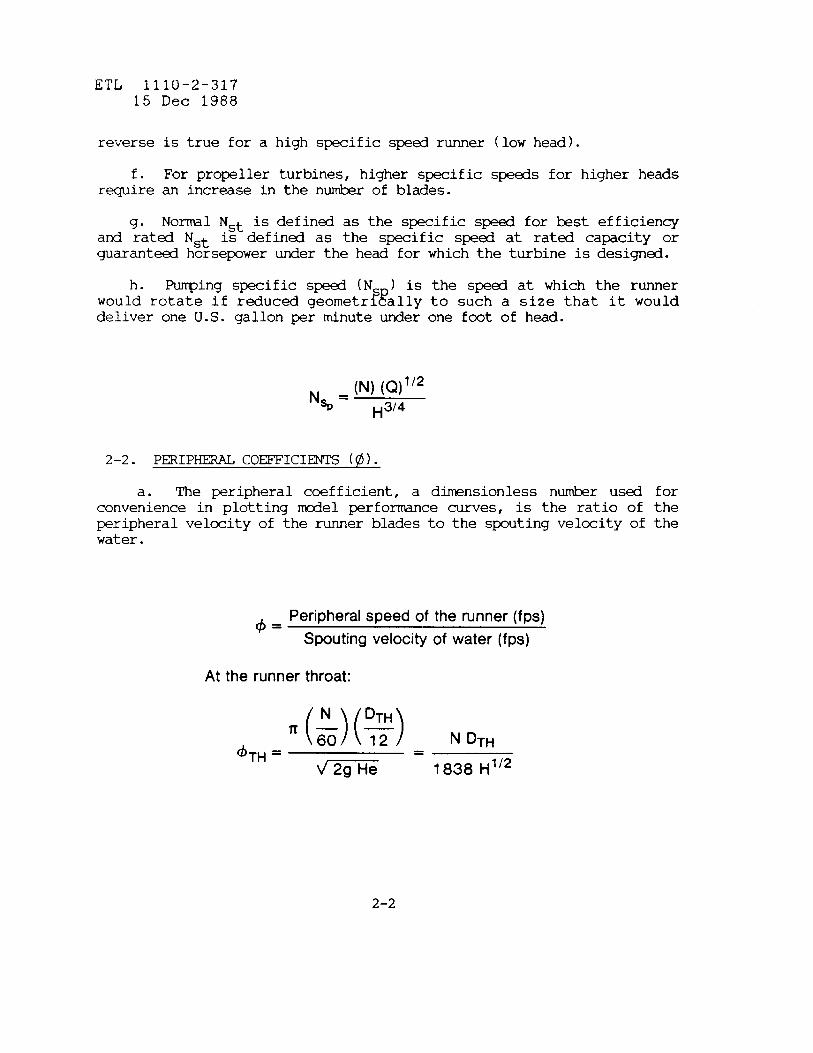
h. Pumping specific sped (N‘~
) is the sped at which the runnerwould rotate if reduced geometrl ally to such a size that it woulddeliver one U.S. gallon ~r minute under one foot of head.
(N) (Q)1t2‘%= ~3/4
2-2. PERIP~ CO=ICIENTS (~).
a. The peripheral coefficient, a dimensionless number used forconvenience in plotting tiel perfo~ce curves, is the ratio of theperipheral velccity of the runner blades to the spouting velocity of thewater.
4=Peripheral speed of the runner (fps)
Spouting velocity of water (fps)
At the runner throat:
,TH ‘(:)(%) NDTH= m= 1838 H“2
2-2

ETL 1110-2-31715 Dec 1988
where
~ = Peripheral coefficient at runner throat
N = Runner speed in revolutions per minute
~ = throat diameter of the runner in inches.
Note: While D may denote any representative dimension of the runnersuch as inlet, throat and discharge di~ters, it is Corps practice touse throat diameter.
g = Acceleration due to gravity = 32.17 ft./sec2
He = Effective head in feet.
b. The runner speed must be selectd to retch a synchronous spedfor the generator (see Ap~ndix A, Page A-6, “G~~R SPEED VS NUMB~OF POLES”).
120 HzN =
n
where Hz = frequency in cycles per secod and n = n-r of pies of thegenerators.
c. While, in general, higher runner speeds for a specifiedhorsepower at a specified head should result in a lower first cost for aturbine, the speed may be limited by the cavitation tendency of therunner, the drop in ~ak efficiency over the normal range of operation,vibration, and @ mechanical design of the turbine or generator. Higherspeeds require a lower setting of the runner with respect to tailwaterand are accompanied by increased excavation and structural costs.Higher speeds also reduce the head range under which the turbine willoperate satisfa~orily.
d. Pump-turbines are mre subject to cavitation in the pqing tiethan in the generating tie. Therefore, the p~ing tie determines thesetting of the runners.
2–3

ETL 1110-2-31715 Dec 1988
2-3. SEITING OF TURBINE AND PUNP-TURBINE.
a. The setting of the turbine or pump-turbine is very ~rtant.Too low a setting would result in unnecessary excavation and structurecosts. Too high a setting could result in excessive cavitation of therunner buckets or blades with a resulting loss in efficiency andincreasd operating and maintenance costs.
The setting of a turbine or p~-turbine can best be determinedby t;; consideration of the Thoma cavitation ccefficient Si~ (ti).
Hb-Hv– H~u=
He
where Hb= BarO~trlC pressure head at elevation of the runner*ve mean sea level
~= Vapor pressure head in feet at water temperature
Hs= For Francis runners is the distance from the lowestpoint on the runner vanes to tailwater in a vertical shaft unit, and thedistance from the highest elevation of the runner band to tailwater forhorizontal units.
Hs= For fixed blade and tiplan runners is the distancefrom the center line of the blade trunnion to tailwater for verticalunits and frointhe highest elevation of the blades to tailwater forhorizontal and inclind units.
H = For diagonal flow runners is the distance fra theEhttom of the ga e to tailwater for vertical units and from the highest
elevation of the blades to tailwater for other units.
He= Net or Effective head on the turbine in feet.
Hs may be positive or negative, depending on whether or not thereferencd point on the runner is ~ve or klow tailwater. When thereferenced point is blow tailwater, it is negative. If “a” is thedistance from the center line of the turbine distrihtor to the lowestpoint on the runner vanes for Francis units and to the centerline of theblades for propeller-type runners, then the distance from the centerline
2-4

ETL 1110-2-31715 Dec 1988
of the distriktor to tailwater for H~ positive is (a + Hs), and for Hsnegative is (a – H~).
. It is custo~ for manufacturers to add a safety allowance tothe c~vitation coefficient Si~ (~).
lib– Hv – H~ – Safetyo =
He
2-4. CRITICAL SIGMA (&c ).
a. Over the years, since facilities for rrakingcavitation testshave ken available, there have ken several mthcds proposed and usedfor determining critical si~ from tiel tests. There has ken nofixed agre~nt on a standard methcd of determining critical si~ andin using Hufacturers’ critical si~ curves. It is important that themethd used in determining critical si~ for a particul~ mcdel beclearly established as a rranufacturermy have used a different methdof determining critical sip, depending on the methcd in use at thet~ of the test.
b. In some tiel tests, the cavitation limits were considered to& at the points where power drops off and the discharge increases, thusdecreasing the efficienq.
c. In other @el tests, critical si~ was considered to k thevalue obtained at the point of intersedion of the constant horizontalHP or Q (pump) curve with the slope of the line under cavitatingconditions.
d. The International Cde for Mdel Acceptance Tests of HydraulicTurbines, I= Publication 193, gives the following three definitions ofsigrra:
(1) Cfo, the lowest value of si~ for which the efficiencyr-ins unchanged as co-ed to non–cavitating conditions,
(2) @l, the lowest value of sigma for which a drop of onepercent in efficiency is attained compared to a non-cavitatingcondition, and
2-5

~TL 1110-2-31715 Dec 1988
(3) d~, Standard Sip, the value si~ at the intersectionof the constant efficiency line (non–cavitating) with the stronglydropping straight line along which measuring points align themselves fora high cavitating degree.
e. The Corps of Engineers Specifications defines “the CriticalSi~ of the turbine or p~ turbine for such desired turbine output orpump capacity and head shall be the si~ corresponding to the tailwaterlevel of such tests which results in a one percent decrease inefficiency or turbine output, or pump power input which ever occursfirst.” (See CE 2201.01, .02 and .03, paragraph MT-4.5).
f. Because of the shape of some mcdel sigma curves, considerablejud~nt is necessary in determining critical sigma.
9“ Prototype experience is necessary to detertine the factor ofsafety to include with Hs and also how much prewelding of the runnerblades can be used as a trade-off against deeper s-rgence.
2-5. P~ORMANCE CURVES.
a. Turbine protot~ performance curves are plots of efficiency anddischarge versus horsepower for various heads and gate openings and arebsed on labratory test data of a mcdel homlogous to the prototypewith regards to runner and water passages.
b. The pwer is step@ up from the tiel by the formula:
“’fl”’m($)’(jr’c. The turbine discharge, negleding any step–up in efficiency, my
be calculatd by inserting the value of horsepower calculated from theformula under (b) ~ve into the formula for turbine horsepower HP =wQHEm/550. H is the net or effective head and Em is the modelefficiency.
d. The expeded efficiency of the protot~ turbine is the mcdelefficiency plus not more than 2/3 of the step–up in efficiency (as determind by the Mtiy formula where ~ is the Himum mcdel
~;b~;
efficiency at best speed or phi (0). The allowable step–up in
2-6

ETL 1110-2-31715 Dec 1988
efficiency is added to all efficiency points to obtain the ~edprototype corrected efficiencies,
()Dm ‘t5EP = IOO–(1OO– Em) y
P
EC()
=Em+ ~ (Ep– Em)
e. No step–up in power is @rmitted by the guide specificationshowever the corrected efficiency is used in calculating prototypedischarges.
~= 550HP
wHe Ec
f. Pumping perfo~ce curves are plots of efficienq, head andhorsepower versus discharge at various gate openings and are &sed onlaboratory test data for a model homologous to the prototype withrqards to runner and water passages. For pumping, unless otherwisestated, the head is the total head from the suction pool to thedischarge of the spiral case. The prototype head and discharge capacityvalues are stepped up from the model by the affinity laws and thecapacity values so determined should not k less than the guaranteedvalues. The p~ corrected efficiencies are obtained by a~ing theallowable step–up in efficiency to all efficiencies points. Theexpected head-capacity curves are developed using corrected capacityvalues which are the values step- up from the tiel multiplied by theratio Ec/~. The expected efficiency capacity curves are develo~using the correctd efficiency and capacity values and the horsepowervalues used in developing the expected horsepwer–capacity curves areco~uted using the formula HP = wQH/550Ec, where Q, H, and Ec are taken
2-7

ETL 1110-2-31715 Dec 1988
directly frm the expected performance curves. The wimum pump inputhorsepwer determined from the curves should not exceed the rMximum pumphorsepower permitted by the specifications.
2-6. MODEL-PROTOTYPE RELATIONSHIPS. Affinity laws and model toprototype relationships for turbines and pun’@turbines are included inAppetiix A.
2-7. GUARANTEES.
a. When available, previous tiel tests can & used as the &sisfor guarantees, the guaranteed efficiency values should be set 1/4percent less than the indicatd tiel efficiencies. See also Paragraph1–11.
b. Likewise, horse~wer guarantees should & set two percent lessthan the values shown on the expected Horsepower vs. Efficiency curvesfor the prototype.
2-8

ETL 1110-2-31715 Dec 1988
CHAPTER3
FRANCIS TURBIW
3-1. GENERAL USE. For many years, Francis turbines were used for lowheads. Tcday they are in general use for heads from 75 feet up to 1600feet while propeller type turbines have replacd Francis type turbinesat the lower heads.
3-2. SPECIFIC SPEEDS.
a. Specific speeds for Francis turbines range from 20 to 90 and isobtained by changing the design proportions of the runner. A generaldiscussion of specific speed is presented in 2-1.
b. A low specific speed Francis runner has a larger entrancediameter than discharge diameter. For a specific speed of approxirrately42, the inlet diameter is approximately equal to the throat anddischarge diameters. For higher specific speds, the inlet diameterbecomes smaller than the throat and discharge diameters. Also thedischarge diameter is larger than the throat diameter.
c. The specific sped (Ns) will rmin constant for any other sizeor head for the same design and the corres~nding sped for anotherhomlogous runner.
d. Care must be taken when using specific speed values to insurethat they are king correctly used. The &st efficiency at ratd headfor a Francis turbine is mtche.d at 85 – 90 percent of the generator KWrating. the normal KW rating of the generator, the horsepowerequivalent of which is used in calculating the ratd specific speed.
e. In the process of selecting a turbine for a specificinstallation, the specific speed should also be determind using thelowest head at which the Himum power must be develo@ (generator KWrating). This will give the highest Ns under which the unit mustoperate and my dictate the seledion of the runner. When the lowesthead is appreciably lower than the average operating head and when thepower requird is exceptionally high in co~ison to the requir~ntunder noml head, it my ~ necessary to install an oversize turbine tomeet the low head capacity requirement. In this case the turbine shaftrraybe sized to meet the generator rating with the provision that theturbine gate o~nings b restridd when operating at heads where if thegate openings were not restricted, the generator rating would beexceeded. The sm head and gate o~ning restrictions apply to turbines
3-1

ETL 1110-2-31715 Dec 1988
where increase in heads under flti conditions could cause a turbineoutput in excess of the generator rating.
f. For many years, hydraulic laboratories did not have thefacilities for testing the cavitation characteristics of Francisrunners. Therefore the cavitation characteristics were esttited on thebsis of experience with installations of similar t s.
FDuring this
period a value of 632 was used for K in Ns = K/H 2. In 1951 themufacturers of hydraulic turbines rec~nded a K value of 650 to beused in the -ve formula on the hsis that the vertical Francis-tpturbines could usually be set with the centerline of the distri~torshut eight feet ~ve tailwater at sea level. More recent experienceindicates an econdc advantage for smaller, higher sped units withdeeper settings consistent with a K value of approxktely 700. Thisrelationship is shown on Figure 1, Append& C d is recomndd forpreliminary studies.
3-3. D~PMENT OF PR~E P~RMANCE CURVES FROM MODEL TESTS.
a. Mcdel test curves covering a wide range of specific speeds areshown on Figures F1 through F8 in Section I, Appendix D. This methcd ofrepresentation is comnly referral to as “oak tree” or performcehill. The latter designation derives frointhe fact that the figure isthree-dhnsional, as each constant efficiency contour represents acmrdinate point in the Z-direction pexicular to the plane of thepaper. All data has &n rduced to unit values corresponding with= 12 inches (one fret) and head, H = one foot. %The ordinate is unlhorsepower, Wl, and the abscissa is peripheral sped coefficient, @ .All efficiencies are hsed on
9= 12 inches. FThe indicated speci ic
speed is referred to the point o rMximum efficiency. Some cavitationcharacteristics are shown on Figures S1 through S5, Section IV, AppendtiD.
b. The significant characteristics of the eight designs arecoped on Figure F9 of Appendix C. A number of other designs haveken included to aid in the correlation of the data with res~ tospecific speed. The curves may & usd for preliminary selection of therunner throat diameter, sped, design discharge and runner setting. Thecurve of critical runner sigma is based on a horsepower that is 15percent greater than the horsepower at best efficiency. The curve mstnot & used for off–best phi conditions. For studies requiring mrecomplete information rq=ding the turbine dimensions and perfo~ce, aselection must be mde frm one of the eight designs.
c. Pertinent dimensions of the turbine parts and water passages,
3-2

ETL 1110-2-31715 Dec 1988
expressd as a ratio to ~, are shown in Tables 1 and 2, and Figure 4of Appendix C.
d. The following steps are mde to seleti a turbine:
(1) Given the horsepower corresponding to 85 - 90 percentgenerator rating at rated head, a preliminary value for N~ can beselected from Figure 1, Appendix C. A design is selected from FiguresF1 through F8 with a spcific speed which mst nearly approximates thepreliminary value. The design specific sped iscalculations. S~ed N is determind from N = N ~5~~~~}~2theensuing, but N mustbe adjusted to a synchronous speed. It issusually necessary toinvestigate three synchronous speeds in order to arrive at the mstoverall economic speed.
(2) Having selected a s~d, a preliminary runner diameter rrayk determin
@using the selected design and the relationship of @ = N
~/1838 H1 Eand ~ rrayb adjusted to get Om at ratd head to ator near best gate. Also, it may be necessary to change the runnerdiameter so the HPl picked off from the performance hill for the phivalues correspotiing to other head conditions will give the requiredprototype horsepower. This my necessitate a change in sped with acorresponding shift away from bst phi at rated head conditions. Thisincludes calculating @~ for the minimum head conditions at which thecapacity value of the unit or units is .bsedr and the horsepwer outputat this head. It my b necessq as stated ~ve to readjust N and ~to get the necessary HP, when stepped up to give the requird prototypehorsepower at the minimum head condition. See also comnts under 3–2(e) regarding the necessity of installing an oversize turbine to meetthe low head capacity requirmnts.
(3) Performance curves may now be developed from the modeltests using the appropriate tiel - prototype relationships included inAppendix A.
e. As previously pointed out, hydraulic turbines are not off–the-shelf items of equipmt. Mdel tests previously mde and prototypes ofmcdels test are indicative of the performce that can k expected andthe turbine mufacturer can alter or design a tiel bsd on experienceto meet the requirmnts specified for a particular procurement. Thisaccounts for some of the scatter of points shown on Figure F9 ofAPpetiix D.
f. For specific speeds Ns = 33 and below, increasing the vent(i.e. opening between tuckets) will permit increasing the power and
3-3
ETL 1110-2-31715 Dec 1988
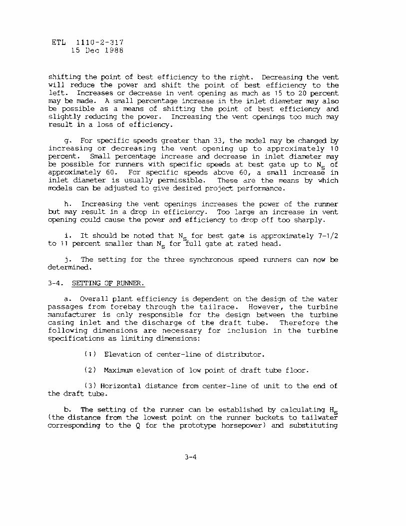
shifting the point of best efficiency to the right. Decreasing the ventwill reduce the power and shift the point of best efficiency to theleft. Increases or decrease in vent opening as much as 15 to 20 percentmy & rode. A smll percentage increase in the inlet diameter may alsobe possible as a mans of shifting the point of kst efficiency andslightly reducing the ~wer. Increasing the vent openings too much mayresult in a loss of efficiency.
9“ For specific speeds greater than 33, the tiel my & changed byincreasing or decreasing the vent opening up to approximately 10percent. Smll percentage increase and decrease in inlet diameter may& possible for runners with specific speeds at kst gate up to Ns ofapproxhtely 60. For specific speds tive 60, a smll increase ininlet diameter is usually permissible. These a_rethe means by whichtiels can be adjusted to give desired projed perfo~ce.
h. Increasing the vent openings increases the power of the runnerkt my result in a drop in efficiency. Tm large an increase in ventopening could cause the power and efficiency to &op off too sharply.
i. It should k noted that Ns for &st gate is approximately 7-1/2to 11 percent smiler than Ns for full gate at rated head.
. The setting for the three synchronous sped runners can now kdet~nd.
3-4. SETTING OF RU’NNER.
a. Overall plant efficiency is dependent on the design of the waterpassages from forebay through the tailrace. However, the turbinemanufacturer is only responsible for the design ktween the turbinecasing inlet and the discharge of the draft tube. Therefore thefollowing dimensions are necessary for inclusion in the turbinespecifications as limiting dimensions:
(1) Elevation of center-line of distrihtor.
(2) Maximum elevation of low point of draft tube floor.
(3) Horizontalthe draft tube.
b. The setting of(the distance frm thecorresponding to the Q
distance froincenter-line of unit to the end of
the runner can k established by calculating H~lowest point on the runner buckets to tailwaterfor the prototype horsepower) and s@tituting
3-4

ETL 1110-2-31715 Dec 1988
the value of sigma obtained from the mcdel tests curves for Hplcorresponding to the prototype horsepower in the formula:
Hs=Hb-Hv – safety – dH
Bpending on the value of si~, H may be positive or negative.The setting of the httom of the runner b~ades IMy be ~ve or below theelevation of the tailwater corresponding to the discharge Q for theprototype horsepower. The distance ratio from the centerline of thedistriktor to the httom of the runner is listed in Tables 1 and 2,Appendix C. This ratio multiplid by the protot~ runner diameter,DTH, gives the dimension which when added to or subtracted from Hsyields the setting for the centerline of the distributor of theprototype.
c. In determining the setting of the runner, the possibility oflower future tailwater levels due to degradation of the river channel&low the darnmust be considered. Also, the time required for kild–upof tailwater under low load factor operation cotiitions, if applicable,must k considered. Mth factors dictate a lower setting. Foundationconditions at the site my Me it economically desirable to set theunit higher by using a lower specific sped runner or to set the unitlower by using a higher specific speed runner. There is also thepossibility of an economic “trade-off” between the rraximumoutput of therunner at the lower heads, cost of excavation, a draft tub with ashorter vertical lq, and more stainless steel pre–welding of the runnerto reduce pitting of the runner due to the higher setting.
3-5. SPIRAL CASE AND DRAET TUBE.
a. While the turbine mar~ufactuer is responsible for the design ofthe water passages from the turbine casing inlet to the discharge of thedraft tube, there are limitations which are prudent to impose such asthe velocity at inlet to the spiral case, the number and width of drafttube piers, the velocity at discharge of the draft tube and theelevation of the lowest pint of the draft tube that will k permitted.
b. The di~ter of the inlet to the spiral case my & the same as,or preferably less than, that of the ~nstock ht the velocity at theinlet should not exceed 22 percent of ~ If the velocity is higher,a loss in efficiency and pwer result. There my & instances where itis desired to install, in an existing plant, a larger unit than thestructure was designd to acc~te. In this case the increased headloss (HL) &tween the net head measurement section and the runner isapproximately 2/3 of the increase in velocity head. The reduced
3-5

ETL 1110-2-31715 Dec 1988
efficiency E and power ~ can k calculatd by the following:
E (H – HL)E,=
H
()H-HL 3’2HPr=HP H
vl =V2 =Al .A2 .
Velocity at the inlet of the noml casing.Velocity of the smiler casing.Area of inlet of the noml casing.Area of the smaller casing.
c. Deviations from strictly homlcgous water passagesaffect runaway speed, thrust, critical sigma as well as designparts.
d. While prwedures hsed on @el laws and tiel atitests are necessary to the study and selection of equipment,to k augmentd by skills and judgment acquired by experience.
my alsoof roving
prototypethey n-
3-6. R~AWAY SPEED.
. The runaway speed of the prototype turbine is determined fratie; tests by running the tiel at various gate opening for the fullranqe of mcdel ~M (N,) or phi (0) to rraximumRPM or @ at minimum valuesof efficiency and power and extending the curvescorresponding value, @mqx., is shown on Figures F1Appendix D. Prototype umum runaway speed is given by
N (E)(:)(2’H)”2~==~max DTH
1838 ~m~ H“*=
DTH
to zero. Thethrough F8 ofthe following:
3-6

ETL 1110-2-31715 Dec 1988
b. It is difficult to design a generator to withstand the highestoverspeed conditions. Therefore, it is sowtimes necessary to limit therMximum gate opening of the prototype turbine in order to limit theoverspeed.
c. While runaway speed is affected by sigma, for all practicablepurposes, its effect, on a Francis turbine can be neglected.
d. With medium head Francis turbines the rMximum oversped occursat full gate but for higher heads where the inlet diameter of the runneris somewhat greater than the discharge diameter, the rMximum runawaysped may occur at less than full gate
3-7. DRAF1’TUBE LINERS. Draft tube linersequal to at least one discharge diameter ofof attachment to the httom ring.
3-8. AIR ADMISSION.
should extend a distancethe runner below the point
a. When Francis units are operating at part gate, air must beadmitted to the center of the runner cone or hub. An air valve,mechanically connected to the wicket gate mechanism controls theadmission of air. If the tailwater can be higher than the elevation ofthe valve and also, if a tailwater depression system is used, a checkvalve must k installd. Depending on the specific speed of the turbineand its required stirgence, it may & necessary for the runner to havealternate passages to admit air through the runner relief holes and touse a compressed air supply for air admission.
b. For a required horsepower at a given head, higher specificspeeds will require deeper settings and increasd air admission at partgate opening for stable operation. It will also be necessary in somecases to provide fins in the draft tb to reduce pwer swings to anacceptable level.
3-9. RUNNER SW CHAMBER DRAINS. When runner seal drains are required,the seal chamber pipe drain header should discharge in the vertical lqof the draft th at a lccation furthermost away from the draft tbexit.
3-1o. SAMPLE CALCULATIONS. The basic calculations for a typicalinstallation are includd in Section 1, Appendix E.
3-7

ETL 1110-2-31715 Dec 1988
CHAPTER4
PROPELLER mINEs
4-1. ~ USE.
a. Propeller type units, operating at higher speeds and at headsless than 100 feet, have generally replaced Francis turbines. Fixedblade units generally operate over a head range of 6 to 120 feet whileadjustable blade units operate up to 250 feet. They have fewer bladesthan the Francis runner has tickets and consequently do not r-ire asclose a spacing of trash rack &s.
b. Fixed blade propeller units are kst suitd to a narrow range ofoutputs due to peaked efficiency curves. Kaplan units have adjustableblades which can operate under rducd heads while maintaining gdpower outputs, have high part gate and overgate efficiencies and can bemde responsive to changes in wicket gate opening.
c. Fixed blade propeller units are appropriate where operation will& at or near constant load with SW1l variations in heads. Capitalcost will k 25 percent less than adjustable blade units for operationunder the same conditions.
d. While adjustable blade units meeting the same conditions couldbe of smiler diameter and possibly operate at a higher s-, they alsohave higher runaway speeds and require a lower setting or submergence ofthe blades.
4-2. SPECIFIC SP~S.
a. A general discussion of specific speed is presentd in paragraph2-1. The usual range in specific speeds is from 82 to 205 for fixedblade propeller type units and 90 to 220 for the adjustable bladepropeller type (fiplan). The number of blades will vary from four toeight depending on the range in head, specific speed, and setting.
b. Care must be taken when using specific speed values to insurethat they are being correctly used. The best efficiency horsepower atrated head for a ftied blade propeller turbine is matched to 90 – 95percent of the generator KW rating. The horsepower equivalent of the KWrating is used in calculating the rated specific sped, the blade angleor tilt of the blades being selected to best suit the project
4-1

ETL 1110-2-31715 Dec 1988
requirements. The ratd output of a Kaplan turbine is usually matchedwith the KW rating of the generator at rated head near full gatehorsepower at maximum blade angle. The horse~wer equivalent of therating is usd in calculating the rated specific speed.
c. A nhr of existing propeller turbine installations have beenexamind to develop some general rules for the preliminary selection ofspecific speed with respect to
bead. This information has been
s~ized in the form, Ns = K/Hi , and is presentd on Fi~e 3 ofAppendix C. The normal range in heads and associated K values for four,five and six blade runners shown on the curve sheets are recomnded foruse in determining the first value of Ns. A preliminary value for speed(N) is then calculated from the formula:
N~ H514N=
HP’i2
4-3. MOD~ TEST CURVES.
a. Typical perforrrancehill curves developed from mcdel tests,covering both fixed and adjustable blade propeller turbines are shown inAppendix D, Section III. These curves follow the same format as thatadopted for the Francis turbine designs (refer to paragraph 3–3a).Pertinent dimensions of the turbine parts and water passages, expressdas a ratio to ~ are shown in Tables 4 and 5, and Figure 5 of Apwndixc.
b. In the fixed blade design the inclination of the blades or bladeangle dictates the capacity of the unit. However, increases in theblade angle are accqied by redudion in the peak efficiency. Thisgenerally dictates a comprtise depending upn the requirements of theproject. Mcdel test curves for an adjust~le blade turbine having thesame number of blades and approx~tely the same pitch ratio can behelpful in evaluating the effect of change in blade angle onperfo~ce, bearing in mind that the smaller hub diameter of the fixedblade turbine will result in some increases in power and efficiency overan adjustable blade turbine of the same runner diameter and number ofblades. The pitch ratio is the ratio of the blade length to blade pitch(L/T). This ratio is generally referred to the blade periphery wherethe blade pitch is equal to the circumference generated by the blade tipdividd by the number of blades. Critical sip can be greatly affeded
4-2

ETL 1110-2-31715 Dec 1988
by blade design and blade area, and ~le blade area is necessary tokeep sips within acceptable limits.
4-4. P~IMINARY DATA FOR FIXED BLADE TYPE.
a. The fixed blade hill curves shown in Appendti D are bas~- ondesigns that were developed to satisfy specific requirements. Theirrespective specific s~eds at the point of mimum efficiency are: 141(Figure FBI, Appendix D.) 119 (Figure FB2) and 106 (Figure FB3).Referring to Figure 3 of Appendix C it may be noted that these designsare ideally suited for heads of 32, 57 and 88 feet, respectively. Theymy be used for other ratd head conditions with the precaution that thecalculated speeds and runner throat diameters will b at variance withnorml Corps practice. In the lower head range this error tends toprduce larger, slower speed units, whereas, in the upper head range ittends to produce smiler, higher speed units.
b. If the user is chiefly interested in the size and speed of theunit, the following approxtition will prcduce results more consistentwith norrralCorps practice. For rated conditions, compute the speedusing the methd presented in paragraph 4-2c. The peripheral speedcoefficient can be est~ted from the relationship:
4TH = 0.089 N~O.58
The runner throat di-ter is calculated through the equation:
1838 @TH H’/2DTH =
N
c. The following prmedure is used to c~ute prototype data fromthe hill curves in Appendix D.
(1) Pick off ~1 at desired @~ and efficiency. This pointwill generally coincide with the wimum efficiency. Determine ~ fromthe equation:
4-3

ETL 1110-2-31715 Dec 1988
()DTH 2HF=HP1 ~ H312
()
HP 112DTH = ;:4 HP,— .
(2) Calculate N from the equation:
1838 (#)THH 1‘2
N =DTH
(3) N must & adjustd to the nearest synchronous speed.
(4) Readjust ~ ti repeat steps (1) - (3), if requird.
(5) Check performance required at other heads. Computedperformance full gate horsepowers should be at least 2 percent higherthan the required horsepower to allow for governing and variations suchas mufacturing tolerances.
(6) The next step is to determine the setting by c~uting HPlfor the requird horsepowers, picking off from the si~ curves thecorresponding value of critical sigma and solving for Hs in the formula:
(7) Usually it is necessary to investigate three synchronousspeds in order to arrive at the most overall economic sped.
4-4
ETL 1110-2-31715 Dec 1988
4-5. PRELIMINARY DATA FOR ~STABLE BLADE ~E.
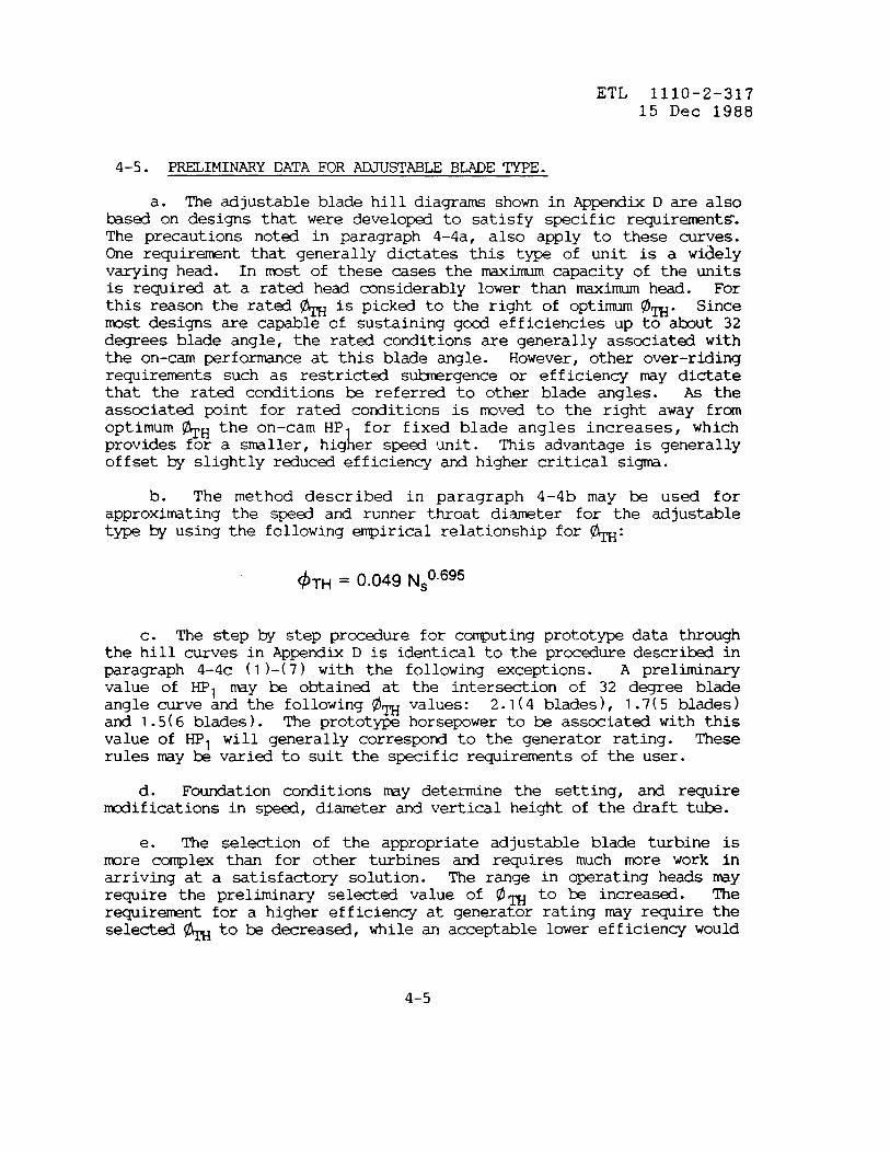
a. The adjustable blade hill diagrams shown in Appendix D are alsohsed on designs that were developed to satisfy specific requirements.The precautions notd in paragraph 4-4a, also apply to these curves.One requirement that generally dictates this t- of unit is a wiselyvarying head. In most of these cases the Himum capacity of the unitsis required at a rated head considerably lower than rraximumhead. Forthis reason the rated ~ is picked to the right of optimum ~~. Sincemost designs are capable of sustaining gocd efficiencies up to but 32degrees blade angle, the rated conditions are generally associat@ withthe on-cam perforrranceat this blade angle. However, other over-ridingrequir~nts such as restricted stirgence or efficiency rraydictatethat the rated conditions be referred to other blade angles. As theassociated point for rated conditions is roved to the right away fromoptimum ~H the on–cam HP
kfor fixed blade angles increases, which
provides for a smiler, hig er speed unit. This advantage is generallyoffset by slightly reduced efficiency and higher critical si~.
b. The method described in paragraph 4–4b may & used forapproximating the speed and runner throat diameter for the adjustabletype by using the following ~irical relationship for ~:
4TH = 0.049 N~O.695
c. The step by step prccedure for co~uting protot~ data throughthe hill curves in Appendti D is identical to the procedure descri= inparagraph 4–4c (l)-(7) with the following exceptions. A preliminaryvalue of HPl may & obtained at the intersection of 32 degree bladeangle curve and the following @~ values: 2.1(4 blades), 1.7(5 blades)and 1.5(6 blades). The protot~ horse~wer to ~ associated with thisvalue of HPl will generally correspond to the generator rating. Theserules may be varied to suit the specific requirmnts of the user.
d. Foundation conditions may determine the setting, and requiremodifications in speed, diameter and vertical height of the tiaft tube.
e. The selection of the appropriate adjustable blade turbine ismore complex than for other turbines and requires much mre work inarriving at a satisfadory solution. The range in operating heads mayrequire the prelimin~ selected value of Om to be increased. Therequirement for a higher efficiency at generator rating my require theselected ~ to be decreased, while an acceptable lower efficiency would
4-5

ETL 1110-2-.31715 Dec 1988
permit the @m to be increased. The horsepower requirements at minmhead may require a change in speed, runner throat diameter and . The
9value of critical sigma rrayrequire a change in HPl which WOU1 aff~the runner diameter and require a change in speed and/or @TH. Theeffect of all these ramifications on the cost of the turbine, generatorand powerhouse structure must be fully considerd in making the finalseletiion.
4-6. SEITING OF RUNNER BLADES.
a. Overall plant efficiency is dependent on all portions of thewater passages from forebay through the tailrace. The turbinerranufactureris generally responsible for design from the turbine casinginlet to the discharge of the draft tube subject to such limitingdimensions imposed by other considerations and mde part of the turbinespecifications.
b. The tiel test infomtion included in Appendix C includes theprincipal model dimensions of the semi-spiral or spiral casing, drafttube and runner dimensions.
c. The following dimensions are necessary for inclusion in theturbine specifications as limiting dimensions:
(1) Elevation of the
(2) Elevation of the
(3draft t~.
(4
d. The
center line of distrihtor.
low point of draft tb flmr.
Horizontal distance from center line of unit to end of the
Limiting dimensions and elevations of water passages.
formula shown in 4–4 c. (6) is used to calculate the settingof the runner blades. The datum for defining Hs is descri~ in 2-3 b.The value of critical sip, dc, is obtained from the mcdel test curvesat the HPl corresponding to the rated output. Depending on the value ofsi~, Hs may be negative or positive, although it is usually negativefor propeller units. Refer to paragraph 2-3.
e. A safety factor must be added to the calculated values of Hs aspreviously discussed under Paragraph 2-3 c., and
Hs = Hb - Hv - &c H - Safety
4-6

ETL 1110-2-31715 Dec 1988
f. When using mufacturer’s tiel curves, the mufacturer’ssafety fa~or should be carefully considered in determining the settingof the runner. One rranufacturerrec~nds a safety factor equal to 0.2
%+ 0.7 H, where ~ and H are in feet. This safety factor does n~
t e into consideration the pre–welding of stainless steel on the lowpressure side of the blades to mitigate the removal of metal from-thesurface of the blade by cavitation. Considerable judgment is requiredin determining the setting of a turbine with consideration for then-r of units to & installed, the methcd of operation and tailwaterelevations for initial and ulthte conditions.
4-7. S~I–SPIRAL AND SPIRAL CASING, AND Dm TUB=.
a. The turbine mufacturer is responsible for the design of thewater passages frm the entrance to the turbine casing inlet to thedischarge of the draft tb. Design conditions and limitations, such asvelocity at the inlet of the semi–spiral casing, velocity at thedischarge of the draft tube and setting the width of the semi-spiralcasing should k set by the Corps. These conditions my also includethe exit dimensions of the draft tube including the width and number ofpiers, and lower than normal distances from the center line of thedistrititor to the httom of the draft tube and from the center line ofthe distri~tor to the rmf of the semi-spiral casing.
b. Deviations from strictly homologous water passages may alsoaffect runaway sped, thrust, critical si~ as well as design of rovingparts.
c. Procedures bsd on tiel laws and mcdel and prototype tests arenecessary to the study and selection of equipinent,however, they need to& au~nted by skills and judgment acquird by experience.
d. For c~nts regarding spiral casing see paragraph 3–5.
4-8. RUNAWAY SPEED.
a. The runaway speed of the prototype turbine is determind from@el tests @ running the mcdel at the various gate openings and bladeangles for the full range of @el RPN (Nl) or ~ to wimum RPN or
9at minimum values of efficiency and power and -ending the curves ozero.
b. As runaway speed is affected by sigma it is also necessary torun si~ versus runaway N or ~ for a range of gate openings and bladeangles.
4-7

ETL 1110-2-31715 Dec 1988
c. Prototype maximum runaway speed is given by
1838 @THH1’2(1) N~a=
DTH ~ @TH =
or
the following:
max value
()m H1’2,N1 =max value(2) Nma = NI &
d. Restricting minimum blade angle and/or Himum gate opening is ameans by which runaway s~ed can ~ reduced.
e. When the blade angle is restridd, the turbine will operate atreduced efficiency throughout the lower range of output.
f. When the blade angle is restrided, the outer edge or tip of theblade is required to k mchined to the contours of the discharge ringwith the blades locked in a position corresponding to the minimumangular position of from 14 to 20 degrees with 16.5 degrees king theusual minimum angular position specified. While restritiing the bladereduces the flexibility of operation and the efficiency of the turbineat horsepowers below the blade angle restriction, it decreases themaximum runaway speed and improves the efficiencies at and *ve theblade angle restridion with the greatest increase being in the range ofthe lower heads. Restricting the blade angle has mde it possible todesign generators for installations where otherwise it would bei~radicable to design generators to withstand the higher overspeeds.When units with restricted blade angles are operated as “spinningreserve” or mtoring as synchronous condensers, the energy taken fromthe system is greater than it would be if the blade angle were notrestricted; however, the economics are invariably in favor ofrestricting the blade &gle.
4-9. DRAFT TUBE LINERS.
Draft tube liners should extend a distancedischarge diameter of the runner below the pointbttom ring.
4-1o. AIR ADMISSION.
equal to at least oneof attachment to the
a. Ftied blade turbines require the installation of air valves
4-8

ETL 1110-2-31715 Dec 1988
connected to the wicket gate mechanism to control the air which must beadmitted to the center of the runner cone or hub, the same as forFrancis units. A check valve must be installed if the tailwater will behigher than the elevation of the valve or if a tailwater depressionsystem is used.
b. Adjustable blade turbines require large automtic air inletvalves, fittd with dash pots to open on sudden load rejection in orderto break the water column upon the gate closure. The air valve mustalso act as a check valve to prevent the outflow of air or water.
4-11. SLANT AXIS ~STABLE-BLADE TURBINES.
a. The Corps of Engineers has used axial-flow adjustable-bladeturbines of the slant (inclined) axis type in three low head projects.Engineering studies indicatd a considerable savings in the first costof these projeds. Due to problems with these units, operation andmaintenance costs have teen high. Also, consider~le down time hasresulted from turbine problems. For these reasons, consideration ofslant axis units should be limited to sites where small units arerequired and there is an economic advantage.
b. The first installations designed by the Corps of ~gineers werefor the Ozark and Webber’s Falls Projects, hth on the Arkansas River.(Rated head - 21 feet. Head range 17 to 34 feet). Each turbine was setat an angle of 12 degrees to the horizontal and drives through a 33,800horsepower speed increaser a 20,000 KW generator. The size of theturbine was limited by the horsepower of the speed increaser.
c. S&equent progress in design has permitted a direct connectionbtween turbine and generator, thereby eliminating the need for a speedincreaser. This design has &en adoptd for the Harry S. Tr~ Project(Kaysinger Bluff) pump turbines which have their shafts inclined at anangle of 24 degrees. Each unit is rated 42,400 horsepower wheno~rating as a turbine at a net head of 42.5 feet and the range in headsis from 41 feet to 79 feet. These are adjustable five blade units andare capable of operating as a pump at a range in pumping heads frm 44to 55 feet. The size of the pump-turbine was ltitd by the physicalsize of the generator–rotor that could & installed, maintaining therequired concrete dimension between the generator housing and the top ofthe draft tb.
4-12. SAMPLE CALCULATIONS. The basic calculations for typicalinstallations are included in Appendix E.
4-9

ETL 1110-2-31715 Dec 1988
c~ 5
PUMP TURBINES
5-1. GENERAL.
a. Pump turbines are dual pu~se mchines. They operate as a p~in one direction and a turbine in the reverse diredion.
b. A pump will perform in reverse rotation as a good turbine.However, a turbine does not generally operate in the reverse rotation asa good pump. Consequently, the design of a pump–turbine impellerfollows mre closely pump design practice than turbine design practice.
c. There is a dependentoperation and a compromise canover the other.
relationship between the two modes of& made to favor one rrcdeof operation
5-2. BASIC CLASSIFICATIONS.
There
1.
2.
are three bsic classifications of p-–turbines:
Radial flow – Francis type
Mixed flow or diagonal type – Fixed blade and adjustableblade (Deriaz)
3. Axial flow or propeller type – Fixed blade and adjustableblade (wplan)
5-3. RADIAL FLOW - FRANCIS TYPE.
. Francis type p~-turbinesto 1~00 feet.
b. The design of the impeller
have ken installed for heads of 75
is basically that of a pump impellerrather than that-of a turbine runner. The i~ller has fewer and longerblades than does a turbine runner with a view to effecting an efficientdeceleration of flow in the water passages. The overall diameter of apump–turbine runner is of the order of 1.4 times larger than theconventional Francis turbine runner. This is due to the requirementsfor a larger discharge diameter than eye (throat) diameter in thepumping -e. A lower runaway speed results, due to to the chokingaction of the impeller on the flow at higher speeds. Thischaracteristic affects the cost of the water passages and the cost of
5-1

ETL 1110-2-31715 Dec 1988
the rotating parts of the pump-turbine and motor-generator.
c. As the unit is designed as a pump, it may be preferable toestablish the pumping capacity for a specific total head which fixeswithin narrow limits the turbine capacity. This is particularly truefor a combind installation of p~–turbines and turbines. Followingthe selection of the p~ing capacity of the p~-turbine unit to fitthe desired program of operation, the turbine capabilities in thegenerating tie is determind and the rating of the conventional unitsfixed to give the desired generating capacity for the several specifiedhead conditions.
d. If the installation is strictly a pump-storage scheme, then theselection of the unit would bin with the determination of the requiredgenerating capacity at minimum head and the n-r of units to providethis capacity. Establishing the generating capacity for a given typeand specific speed determines within a narrow range the pumpingcapacity. Establishing the pumping capacity for a specified total headalso establishes within narrow limits the generating capacity for thecorresponding turbine.
e. It is custo~ to guarantee the discharge in the pumping deof a pump-turbine only at rated head or near best efficiency.
f. Only if a suitable runner is available from existing tests is itpracticable to specify very closely the requirements for both thep~ing and generating cycles.
9“ Economics generally favors the higher capacity units unless anexcessive number of runner splits is required by mchining or shippinglimitations. The design of split runners bec~s mre difficult withhigher specific speeds. Runaway speed for higher capacity units is alarger percentage of synchronous speed and the centrifugal force *esthe design of the splits more difficult as the additional metalincreases the centrifugal force and the stress level.
h. Head losses through the draft tb of a pq-turbine decreasethe net available suction head and increase the runner’s sensitivity tocavitation. Therefore, p-turbine runners must be set deeper thanturbine runners. In order to reduce the size and cost of p-turbines,higher specific speeds are utilized for purr@-turbinesrelatively toturbines ti consequently require deeper settings. The unit is moresubject to cavitation in the p~ing tie than in the generating mode.Therefore, the p~ing tie determines the setting of the runner.
5-2

ETL 1110-2-31715 Dec 1988
i. While in general higher specific speeds for pq turbines rrayappear to be desirable for economic reasons; efficiency, cavitationcharacteristics, mechanical and hydraulic design must & evaluated todetermine the most favorable specific s-. Cavitation increases withhigher specific speds. The use of mtals more resistant to cavitationdamage may allow the acceptance of higher cavitation levels.
“,
j“ Transient Behavior. A transient in hydro-power is the historyof what occurs between two states of equilibrium. A study must be m e
$of the transient condition in order to determine the minimum (WK )flywheel effect for the rotating parts of the entire unit. The studyshould include a power failure in the p~ing tie and load rejection inthe generating mcde. The Corps has a cquter pr~am which should beutilized when tiing these studies.
k. Four Quadrant Synoptic Curves.
(1) The necessary infomtion to analyze transient behavior isprovided by mcdel tests mde of the tiel runner and furnished as FourQuadrant Synoptic Curves which show the possible combinations of UnitDischarge (Q,,): under one foot of head and one foot eye diameterrunner versus Shaft Speed (Nl,), under one foot of head for one foot eyediameter in hth p~ing and turbine dirtiions and Torque (T,,), underone foot of head for one foot eye di-ter versus Discharge (Qll), underone foot head for one foot eye diameter for hth p~ing and turbinedirections.
(2) These curves are prepared from test infomtion obtain~from all gate openings in the c~lete turbine and pump performancecurves, plus infomtion from two additional tests. The first one ofthese tests is identical to a noml p~ test except that the sense ofrotation of the impeller and of the torque appli~ to the shaft ueopposite to that for a no-l p~ test with measurements being takenthe a as during normal pq tests. The second test involves rotatingthe impeller in the normal pump direction with water being pumpedthrough the mcdel in the no-l turbine direction by service p~s.(During the test the head, discharge, speed, and torque are measured forvarious gate openings @ shaft spe~s.)
(3) The Four Quadrant Synoptic Curves may also be suppliedshowing the relationship of horsepower and discharge to phi (~) for thevarious gate openings. The curves show the possible combination ofhead, discharge, torque or power in the following ties of operation:
(a) wing operation
5-3

ETL 1110-2-31715 Dec 1988
(b) Dissipation of energy with rotation in the pumpingdirection - flow in the generating direction.
(c) Turbine operation
(d) Dissipation of energy with rotation in the generatingdirection and flow in the pumping direction.
5-4. MIXED ~w OR DIAGONAL ~ (DERIn).
a. The mixed flow or diagonal flow type pq–turbines are used inthe @ium head range up to more than 250 feet.
b. While the mixed flow adjustable blade machine (Deriaz)previously manufactured by the ~glish El@ric Company are presentlymnufatiured and preferred for use in Japan, the less costly Francismixed flow types are preferrd in the U.S.A.
5-5. AXIAL FLOW - PROPELLER TYPE - FIXED AND DSTABLE BLADE.
a. Alternates for use in the low head range, below 75 feet, are theaxial flow machines arranged with the shaft vertically, horizontally orinclined.
b. The Corps of Engineers Harry S. Tr~ (Kaysinger Bluff) projecthas the largest capacity slant axis axial flow p~ storage machinesunder construction as of 1 January 1981.
5-6. SPECIFIC SPEEDS - SINGLE STAGE REVERSIBLE PUMP/TURBINES.
. The turbine specific speed (Nst) of a pump turbine in thegene~ating mcde is defind as the speed in revolutions ~r minute (N) atwhich a pm turbine of hmlcgous design would operate if the runnerwas reduced in size to that which would develop one horse~wer under 1foot of head.
b. The turbine specific sped is expressd as follows:
5-4

ETL 1110-2-31715 Dec 1988
c. The turbine specific speed is somewhat higher than for aconventional turbine, being in the range of K from 800 to 1250, where K=N H 1/2. The range of K for a conventional Francis turbine is 7~to ~~0, &sed on Nst at bst efficiency.
d. The p~ specific speed (N ) of a p~ turbine in the pumping‘8mcde is defined as the speed in rev lutions per minute (N) at which the
Pump turbine runner of homologous design would operate if the runnerwere rduced gemtrically to such a size that it would deliver one U.S.gallon per minute under one fmt of head.
e. The pump specific speed is expressd as follows:
N= N Q“*
Sp “314
Q = gpm
f. A recornnendsdrelationship for selecting p~ specific speedsfor a range of pumping heads is shown on Figure 2, Ap@ndix C.
9“ In selecting the specific speed consideration must be given notonly to p~–turbine and generator rotor costs, powerhouse and auxiliqequipment costs, but to efficiency in both modes of operation,cavitation characteristics, mechanical, hydraulic design features and toany restrictions *seal by foundation and site conditions.
5-7. P~IMINARY DATA FOR FRANCIS PUMP-TURBINES.
a. Mdel perfo~ce data for p~–turbines is shown in Appendix D.This data is basal on tiel tests covering low, intermediate and highspecific sped designs. The original test data has ken reduced to themore convenient form shown on Figures FTl, PT2 and FT3, which are basedon~=12’’andH=l foot. The performance for the generating mcde ispresented in the same format as that adopted in the other Sectionscovering the conventional Francis and propeller turbine designs. Thedischarge, efficiency ti critical si~ curves for the p~ing moderepresent the envelope perfo~ce for bst efficiency from a nhr of
5-5

ETL 1110-2-31715 Dec 1988
fixed wicket gate tests. The curve of pumping specific speeds isderived from the other data. Pertinent dimensions of the pump-turbineand associated water passages, expressed as ratios to ~, are shown inTable 3 and Figure 4 of Ap@ndix C.
b. Infomtion established by the Project Planning and Field SurveyStudies is listed in paragraph 1-5. For the pumping cycle thisinformation includes the p~ing requirements and maximum, minimum andaverage heads.
c. The results of planning studies will generally dictate the ratedpumping conditions. This information should include the rated gpmdischarge and the associated rated dynamic head. An appropriates~cific smd for the ratd head is obtained fra Figure 2, ApFndix C.A-prelimin-~ value for speed (N), is then calculatd-from
~ = N~p H3’4
*1/2
The calculated value is rounded to the nearest synchronous
d. If the user is chiefly interested in the size ofunit, the following empirical relationship may k used tovalue for ~.
the formula:
speed.
the prototypeapprox~te a
@TH = 0.0015 N~~.785
e. The runner throat diameter is calculatd as follows:
1838 @TH H“2DTH= -—
N
f. The following procedure is used to calculate prototype pumpingperformce from the tiel performance curves:
5-6

ETL 1110-2-31715 Dec 1988
(1) Fra Figure 2 pick off the value of N=. corres~nding withthe rated dynamic head. - -P
(2) Inspect the @el ~rformce curves, notingspeed range of each, and select the design that best suitsNSp“
the s~cificthe value of
.
(3) From the selected curves, note the value of Q, for maximumpumping efficiency. Also note that this value is in cfs units. Theprototype runner throat diameter (eye diameter for p~ impeller) iscalculated from the following relationship, where the subscript 1 refersto the mcdel and subscript 2 refers to the prototype:
%=(%)’(%)”2D, = 12 inches and H, = 1 fret.
(4) At this s- point note the value of o~. The pump spedis calculated from the relationship:
N= 1838 @TH H’”
DTH –
Round to the nearest synchronous speed.
(5) Readjust ~ for synchronous speed, pick off a new Q1 fromthe mcdel curves and repeat steps (3) and (4), if required. Continuethis process until the re-adjustd value of @~ and corres~nding Q1from the model curves produce a value of DTH that results in asynchronous s~ed in step (4).
(6) With fixed values for ~ and N, the @~ corresponding toother p~ing heads is calculated from the following relationship:
4TH= N‘TH _ Kn1838H’/2 ~11’
5-7

ETL 1110-2-31715 Dec 1988
(7) For given head and corresponding value of @~ extract Q,from the mcdel curves and calculate the uncorrected value of prototypedischarge from the following relationship:
()DTH 2Q2=Q, ~ H112
(8) The prototype efficiency of the pump-turbine is determinedby the Mocdy formula in accordance with ~-4.5 of Guide SpecificationsCE-2201.02 HYDRAULIC PUMP-TURBINES - FRANCIS TYPE Paragraph MT-4.5. Theefficiencies are increased by the ~ munt in hth the p~ing andgenerating ties of operation. The following formula is applied to thepeak efficiency value:
()Dm 0.2E2 = 100–(l OO– E1) ~
P
E2 - El = step–up in efficiency
Using two–thirds of the step-up, the model efficiencies (El ) areincreased by 2/3 (E2 – El ) to give the expected or prototypeefficiencies, E2.
(9) The values of discharge in step (7) are increased lYYtheratio (E2/E1) to account for the increasd efficiency of the prototype.The increased values are used in plotting the expected head–cfs curve ofthe prototype.
(10) With Q, H and E beinq tAen directly from the perfo~cecurves, the horse~wer-cfs curve i~c~leted usi~g the formuia:
HP_QHw
550 E
5-8

ETL 1110-2-31715 Dec 1988
9“ The following procedure is used to calculate prototypeperformance in the generating mcde from the associated hill curves shdmat the bttom of the tiel curves in ApPndix D.
(1) @TF
values for the range in net operating heads arecalculated from he formula established in (6) ave.
(2) Prototype horsepowers for each head are calculated byintercepting the fixed gate curves at the associated value of @ ,noting the corresponding HP, Rand substituting known values in efollowing formula:
(3) The expected prototype efficiency (E ) is calculated by%adding the step–up determined in f(8) ~ve to t e associated mcdel
efficiency (El), at each fixed gate point.
(4) With HP, H and E king taken directlyperformance curves, the qctd prototype dischargethe following formula:
Q=550 HP
wHE
5-8. S~ING OF PUMP-TURBINE RUNNER - FRANCIS TYPE.
frointhe expectdis calculated from
a. The setting, which is generally referred to the elevation of thedistributor centerline, is determined by critical sigma in the purr@ingtie. The appropriate siy value for each pqing head can be pickedoff directly at each corresponding @TH on the mcdel curves, thenstitituted in the following formula to compute the suhnergence, Hs:
5-9

ETL 1110-2-31715 Dec 1988
Hb– Hv– H~– SafetyUC ==
H
(1) Appropriate values for Hb and ~ are shown on Figure 6,Appendix c.
(2) A rec~ed safety margin is calculated by shtitutingin the following formula:
Safety
where Di is theis qressed asactual diameter
~gin = 0.2 Di + 0.4 H’/2
protot~ runner inlet diameter in feet. This diametera d~nsionless ratio, D, in Table 3 and Figure 4. Theis the product of the ratio t-s ~, in feet.
b. The values of critical sigma from the mcdel tests are referredto the httom of the runner. Likewise, the suhne.rgence(Hs) c~utedabove is referred to this same point. The distance, a, from thedistrihtor centerline to the btta of the runner is expressed as adimensionless ratio, d, in Table 3 and Figure 4. The distance is theprcduct of the ratio times ~, in feet. The setting is calculatd asfollows:
Elevation distributor centerline = Tailwater Elev. + Hs + a
5-9. SPIRAL CASIK AND DRAFT TUBE - NCIS TYPE.
a. The turbine mufacturer is responsible for the design of thewater passages from the upstream end of the turbine casing inlet to thedischarge of the draft tube. Deviations frm the tiel dimensions canaffect performance.
b. ~ing considerations dictate the design of the spiral casingand draft th, except for the nti and width of draft tube pierswhich de- on structural requirements.
5-1o. DRAET TUBE LINERS. Draft tube liners for pq-turbines shouldextend to the pi= noses.
5-1o

ETL 1110-2-31715 Dec 1988
5-11. RUNAWAY SPEEDS.
a. Runaway spedtype pump-turbines areturbines.
tests for Francis type or fixd-blade propellerconductd the same as those for the Francis type
b. The runaway s~d tests for adjustable blade propeller type pumpturbines are conductd the same as for the adjustable blade turbine.
c. The calculation of prototype Himum runaway sped is the sameas that shown in paragraph 4–8c.
d. It is sometimes necessary to limit the gate opening of theprototype Francis pump–turbine to limit overspeed because of thedifficulty of designing a generator to withstand the higher overspeed ofhigh gate openings.
e. The effectneglected, however,turbines.
of sigma on a Francis typesip must k considered for
pump-turbine can bepropeller t= pump-
5-12. AIR ADMISSION. Aninstalled for Francis-typeopenings blow 50 ~rcent.
air and check valve (orPW turbines to permit
5–13. R~ SEAL CHAMBER DRAINS. The seal chmrshould discharge in the vertical leg of the draftfurthest away frm the draft tb exit.
valves) should koperating at gate
pipe drain headertube on the side
5-14. SAMPLECALCULATIONS. A typical calculation for a pump turbineinstallation is included in Ap~ndix E.
5-11

ETL 1110-2-31715 Dec 1988
CHAPTER 6
GENERATORS AND GENERATOR - M~RS
6-1. GENERAL.
a. The hydroelectric generators and generator–motors aresynchronous machines. Both produce electric energy by thetransfomtion of hydraulic power into electric power kt the latteralso acts in reverse rotation as a rotor to drive the pump-turbine as aPump“
b. As hydraulic turbines and pump turbines must k designed to suitthe specific range of conditions under which they will operate, eachgenerator and generator-motor is unique in that the electrical andmechanical design must conform to the hydraulic characteristic of thesite and to the specific requirements of the electrical system.
c. A major difference between a generator–motor and theconventional generator is the special design features inco~rated inthe former required for starting and operating the unit in the reversedirection as a rector.
d. Guide Specifications cover the electrical and mechanicalcharacteristics and the structural details of generators and generator–rotors.
6-2. THE S-ION AND NUMBER OF UNITS.
a. Factors affecting the selection and number of units are outlindin Chapter 1, Paragraph 1–7.
b. The type of generator or generator-motor depends on the type ofturbine or pq–turbine to which it is connected and also whether thecenter line of the shafts will be vertical, horizontal or inclind.
c. Vertical shaft generators connected to Francis and Fixed BladePropeller Turbines have three basic designs:
1. Suspendd Generator - a thrust bearing located on top ofthe generator with two guide ås.
2. Umbrella Generator - a thrust bearing and one guidebearing lccated below the rotor.
6-1

ETL 1110-2-31715 Dec 1988
3. Mdifid Umbrella Generator –thrust bearing located below the rotor andlocated tive the rotor.
d. Horizontal shaft generators usuallycapable of taking thrust in hth directions.not & the same in hth directions.
e. While s- vertical shaft generators
a combination guide anda second guide bearing
require thrust bearingsThe thrust required my
connected to adjustableblade turbines have ken of the umb;ella type, the Corps requires allvertical shaft adjustable blade turbines and all vertical shaft p-turbines to have two guide bearings and one thrust bearing locatedeither -ve or below the rotor.
f. Generators and generator–motors connected to inclined axisturbines require thrust bearings capable of taking thrust in bothdirections (away from and towards the generator) and two guide bearings.
6-3. G~TOR RATING. Generators are rated in kva (electrical output)with the power factor determined by consideration of anticipated loadsand system characteristics to which the unit or units will be connected.
6-4. GENERATOR VOLTAGE AND ~mc!z . Determination of generatorvoltage is hsed on economic factors which include the cost of generatorleads, instrmnt transformers, surge protetiive equi-t,breakers,
circuitspace limitations, the requirmnt to serve local loads and
the generator costs for the various voltage levels available. Thestandard frequency in the U.S.A. is 60 Hz.
6-5. SPEED . The speed of the unit is established by the turbineselectd speed which must take into consideration that some synchronousspeeds have a number of poles which for the kva rating desired would notgive an acceptable winding design. See Table of Generator Speeds inAppendix A.
6-6. m FACI’t)R.The power fader of the generator is determind @the transmission and distritition facilities involved in addition toprobable loads and system characteristics. If the generator isconnected to a long, high–voltage transmission line, it rray& economicas well as desirable to install a generator capable of operating withleading pwer fa~ors. If the project is located near a large loadcenter it my @ econtical to install a generator with larger thannormal reactive capability by using 0.80 or 0.90 power factor mchines.Forthe
the majority of insta-lla~ions0.95 power factors generators will beconomic ones to specify. In general, for kst o~ration the pwer
6-2

ETL 1110-2-31715 Dec 1988
factor of the generators should retch the power factor of the load.
6-7. FL~EFFEcr (WK2).
a. While the moment of inertia (WK2) of the rotating parts “of aunit (generator plus turbine) is a factor affecting system stability,the use of high speed circuit breakers
9relays has in most cases
r~ved the need for higher than normal WK from the stand int of theelectrical system.
3FThen the need for higher than normal WK depends on
the WK needed to keep the speed rise of the unit W the pressure risein the water passages for the turbine or p~–turbine within accepttilelimits.
b. Greater than noml WK2 rraybe required for an isolated plant ora unit serving an isolatd load.
6-8. GENERATOR - M~R RATING.
a. The generator–motor rating depends on the pump–turbinecharacteristics and the system to which it will be connected.
b. Having selected a p~–turbine to meet the required capacityhead conditions, the rotor rating can be determined. In p~–turbineinstallations there may be considerable variations in head andconsequently a variation in the motor requirements. The motorrequirements may dictate the maximum rating of the generator–rotor titin no case should the Himum horsepower required in the p~ing tie bemore than 94 percent of the 100 percent, 75 degree Centigrade nameplaterating, the rotor rating king in KW (shaft output) or its horsepowerequivalent.
c. The power factor de~nds on the system voltage cotiitions andtransformer ieance and usually results in selecting a power factor of0.95 (over-excitd). There rMy be cases, during the hours of p~ing,in which the system voltage may be reduced to where voltage studies showit is necessary for the mchine to operate in the pumping tie at alower voltage than in the generating tie. The range may be such as torequire a dual voltage rating. Usually a difference in ratings forgenerating and motoring of ~ut three percent less can & furnishedwithout undue cost or complication.
6-9. EXCITATION SY-.
a. While for many years the excitation for synchronous generators
6-3

ETL 1110-2-31715 Dec 1988
was provided by directly connected main and pilot exciters, the pilot=citer was later eliminatd and a rotating and/or a static voltageregulator system was used in connection with the direct-connected minexciter. Currently, except for very small generators, a staticexcitation system is specifid. A static excitation system is specifidfor all reversible units.
b. The static excitation system is a static potential-source-rectified type with power for the ~citation circuit normally takendirectly from the generator or generator-rotor leads. The c~leteexcitation equipment consists of the excitation transformer, rectifiers,a–c ~citation power circuit breaker, a-c hs &tween the transfomrand rectifier, silicon controlled r~ifiers, d–c hs from the rectifiercubicle to the generator or generator-rotor field brush terminals, and astatic aut~tic voltage r~lator which controls the firing of theSCR’S. The system designd for a generator–rotor includes the necessaryprovisions for bth directions of operation.
Most of the recent -citation systems have been provided with~we;” system stabilizing equipment which changes the generator fieldcurrent in proportion to instantaneous deviations from normal frequencyto help dampen oscillations. This equi~nt should usually & furnishedwith solid–state excitation systems.
d. The Institute of Electrical and Electronics Engineers “StandardDefinitions for Excitation Systems for Synchronous Machines,” ANSI/IEEEStd 421.1-1986 should be consulted for an understanding of theapplication of solid–state devices to excitation systems. This reportincludes the new and revised definitions for excitation systems asapplied to synchronous machines and gives particular emphasis on solid–state devices. The report includes figures illustrating the essentialelements of an automatic control system, the components corrrnonlyusedd figures which show the actual configuration of principal excitationsystems supplid by domestic mufacturers.
6-10. TI-IRUSTAMD GUIDE BEARINGS.
a. The Guide Specifications require that the generator and orgenerator–rotor & provided with a nonspherical, adjustable-sh= orself-equalizing Kings- type or a General Electric spring type thrustking and for a generator-rotor be suitable for rotation in eitherdirection. For vertical mchines the thrust bearing may be above orbelow the rotor. Units with very high thrust bearing loads - areaswhere space below the rotor is limited generally have the thrust baringlccated *ve the rotor. Locating the thrust bearing below the rotor
6-4

ETL 1110-2-31715 Dec 1988
can reduce costs. Effects of the bearing location on vibration shouldbe considered.
b. The generator of a vertical mchine rray k provided with odeguide baring &low the rotor if the generator is connected to a Francisor fixed blade propeller turbine. ~ upper guide bearing must beprovided if its installation is deemed necessary by the manufacturer forsatisfactory operation or if the thrust tearing provided is of the self–equalizing type.
c. The generator of a vertical mchine connectd to an adjustableblade propeller turbine must be providd with two guide bearings.
d. The generator-rotor of a vertical mchine must be provided withtwo guide ås with provisions for adequate lubrication in hthdirections of rotation.
c. It is now c~n practice to require that thrust bearings bprovided with an externally pressurized system for providing highpressure oil to the thrust karing surfaces during the starting andstopping of the mchine.
6-11. THRUST BEARING Bm THE R~R.
a. When the thrust bearing is located below the rotor the shaftcoupling must be located farther below the stator than when the thrustbearing is located above the rotor.
b. The thrust bearing blcck is required by specifications to beforgd integrally with the shaft.
c. Thrust bearings located below the rotor must be larger indiameter (for the same load carrying ability) than thrust bearingslocated tive the rotor, due to the larger dimter of the shaft at thekaring location.
d. Two mthcds of inspection and removal of thrust baring partsare provided, depending on the manufacturer of the generator orgenerator–motor. One methd provides r~vable karing housing coversin a bridge type lower bearing bracket. With the covers rmved thethrust bearing is exposed for ins-ion and can & r~vd through thespace between the bracket arms without disturbing the min support. Thesecond method involves the lowering of the thrust bearing by use of aspecially designd lowering device into the turbine pit. This designrequires that the shaft coupling be located at a greater distance blow
6-5

ETL 1110-2-31715 Dec 1988
the stator.
6-12. ~UST BEARING ABOVE THE R~R.
a. This design permits access to the bearing parts by overheadcrane and assures ad~ate working space regardless of mchine size andthrust bearing capacity.
b. This location is the standard location for srralland high speedmachines where the space blow the rotor is limited.
c. This lccation does not place a limitation on the size of shaftforging facilities available. Large structural _rs are required tosupport the thrust bearing located above the rotor. These memberssupport the thrust bearing loads and must & stiff enough to minimizedefledions. They have to bridge a larger span than the baring bracketlocated below the rotor.
d. The location doesdoes the thrust karingkaring losses are lower.
not require as large a di-ter of karings aslocated
e. The bearing my be splitas with Kaplan turbines. Thispermits rmval of bearing andpiping.
below the rotor and consequently the
when required for installations, suchnot only facilitates handling, butparts without dismtling the Kaplan
6-13. THRUST BEARING NOT INCO~RATED IN THE GENERATOR OR GENERA~R-.—M~R .
a. Slant axis adjustable blade turbines and p~ turbines require athrust baring design to take thrust in hth dir-ions and my or mynot & purchasd with the generator de~ing on its location.
b. It is the common practice in Europe to procure the thrustbearing with the turbine and to mount the thrust bearing on the turbinehead cover. S- savings is claimed in certain installations by sodoing as it omits the large thrust bearing supports.
c. This lccation presents problems in coordinating the procurementand installation of the bearing. Thrust bearings are customarilyfurnishd by the generator tranufacturersin the U.S. and installed bythem in the generator.
6-6

ETL 1110-2-31715 Dec 1988
d. For very large capacity slow speed units it may k necessary forecon~c reasons to locate the thrust baring on the turbine head cover.
6-14. HIGH PRESSURE OIL SY~. High pressure oil starting system in athrust bearing is essential for the operation of a reversible unit.andshould be specified for any unit over 31,260 kva in rating. To startthese units, the oil is pumped under high pressure through openings inthe stationary segments, forcing lubricating oil btween the stationaryand rotating -s of the bearing hfore the unit is started. Thisreduces the friction and breakaway torque to very low values, andreducing wear. It is also in service during shut-down.
6-15. ~ICAL CHARAC1’ERISTICS.
a. The electrical characteristics of a generator and generator–motor, in addition to determining its individual performance, willaffect the performance of the power system to which it will beconnected. These characteristics can be varied within limits to bestsuit overall performance. The values for these characteristics must beincludd in the procurement specifications.
b. Characteristics of a generator or generator–rotor which have an
-rtant eff~ on the stability characteristics of the electricalsystem are Short Circuit Ratio, Transient Reactance,Performance,
Excites Systemand the electrical damping provided by the WK of the
rotating parts of the units.
c. A short circuit ratio (SCR) is the ratio of the field currentrequired to produce rated voltage at no load to the field currentrequired to circulate rated current or short circuit. With nosaturation, it is the reciprocal of the synchronous ~ce (Xd) and aconvenient factor for comparing and specifying the relative steady–statecharacteristics of generators and generator-motors. The higher theratio, the greater the inherent stability of the mchine. A systemstability study is necessary to determine whether a higher–than-nomlshort-circuit ratio is required. Increasing the ratio above nomlincreases the machine size (the mchine king de–ratd), the normalflywheel effect (WK2) and the machine costs, and decreases theefficiency and the transient reactance of the machine.
d. Some electrical systems require a lower than normal transientreactance. However, when a higher than normal SCR is specified, thetransient reactance will be less than noml. Either the lower thanno-l transient reactance orwill increase the cost. The
the higher than normal SCR, ht not both,cost increase is determined by the more
6-7

ETL 1110-2-31715 Dec 1988
expensive option. Decreasing transient reactance increases faultcurrents.
e. An increase in the rotor inertia (WK2) tive noml increasesthe cost, size and weight of the mchine and d creases the efficiency.
5In a p~–turbine installation increasing the WK of the generator–rotorincreases the starting time in the pqing de. See Paragraph 6–7.
f. ~citer System Performance (See IEEE 69TP154 - PWR).
(1) Mcdern voltage regulator systems have increased the dynamicas well as the steady state stability of electrical systems.
(2) The excitation system should be capable of reversing theexcitation voltage of full negative voltage to rapidly reduce fieldcurrent when required. Capability to reverse field current, however, isnormally not required.
(3) It must be recognizd that S- systems, at times, requireoperation of the generating equipment at voltages below normal. It mustalso be recognized that the excitation system should be capable ofachieving the requird perfo~ce at a specifid voltage available fromthe generator terminals. However, specifying a voltage materially belownormal will increase the size of the excitation equipmnt, the spacerequired to house it, and its cost.
h. -rtisseur Windings.
(1) While -y hydroelectric generators have been provided withnon-continuous mrtisseur windings in the past, continuous ~rtisseurwi~ings are now normally specified for all Corps of Engineers machines.Continuous ~rtisseur windings provide substantial benefits over non-connected windings regarding stability, supplying tilanced loads,effects on hunting etc., as described below. These benefits areparticularly advantageous because of the difficulty in priordetermination of system conditions. Continuous, heavy-duty amortisseurwindings me required for generator-rotors which are to be started asinduction motors.
(2) ~rtisseur windings are designed for a calculated ratio ofquadrature-axis subtransient reactance to direct-axis subtransientreactance not to exc~ 1.35 for an open amortisseur winding and not toexceed 1.10 for a closed winding.
6-8

ETL 1110-2-31715 Dec 1988
(3) The advantages of amortisseur windings ae:
(a) They reduce and in some cases eliminate hunting orsustained pulsations in current and voltage that occur under certa;nconditions of operation of a synchronous generator.
(b) They are effective in reducing the overvoltages dueto unbalanced loads and faults, which can be an ~rtant factor in theapplication of lightning arrestors and in the cmrdination of insulationlevels.
(c) Because they are a material aid in damping outoscillation they are of &nefit in @roving the ability of the machinesto ride through system disturbances.
(d) They provide additional stabilizing torque forgenerators which are automatically synchroniz~.
(e) They reduce circuit breaker recovery voltages bttend to increase the magnitude of the current required to beinterrupted.
(f) They aid in protecting field windings against currentsurges caused by lightning or internal faults and in case of the latterare effective in reducing additional tige to the machine.
(g) They permit pump-turbine motor-generators to bestarted as indudion motors.
(4) ~rtisseur windings increase stresses in the rrachineandconnected equipment due to the increase in short-circuit current. Theadditional winding in the rotor must be hilt to withstti the stressesat mimum overs~ conditions and the stresses in the rotor parts arealso increased. A continuous amortisseur winding complicates thecooling and disassembly of the field coils.
(5) An amotiisseur winding designd for a calculated ratio ofquadrature-axis subtransient reactance to direct-axis subtransientreactance not to exceed 1.35 will increase the price of the machine byapproxirratelyone percent. For a ratio not to exceed 1.10, the priceincrease is approximately three percent. For a continuous windingsuitable for use in starting, the price increase is five percent due tothe increase in th~l capacity of the winding required.
6-9

ETL 1110-2-.31715 Dec 1988
6-16. METHODSAVAILABLE FOR STARTING PUMP-mI~ IN THE PUMPING MODEOF OPERATION.
a. The methds for starting p-turbines in the pumping tie ofoperation can k classified into three groups, namely: Group 1 whichrequires continuous ~rtisseur winding; Group 2 which does not requirecontinuous amortisseur windings; and Group 3 which requires separatesttiing devices.
b. Group 1 Starting Methds: Four methcds of starting the unit asan induction motor with full or reduced voltage applied to thegenerator-motor terminal as follows:
(1) Full voltage start.
(2) Reduced voltage start.
(3) Part winding start.
(4) Rduced frequency induction start. This method utilizesanother generator or generator-motor which my & isolatd for startingduty.
c. Group 2 Starting Methds:
(1) Synchronous start.
(2) Static converter start.
d. Group 3 Starting Methcds:
(1) Wound rotor induction motor start - Pony motor.
(2) Shaft connected starting turbine.
(3) =citer sttiing.
e. The first three methds und~ Group 1 are applicable only totierately siz~ units. Of these methds, the full voltage methcd hasthe lowest cost in its applicable range because no extra switchingequipment is required. It also has the shortest starting time of anymethcd (approxtitely 20 to 30 seconds). Because of the large startingkva that the full voltage method requires (unless the unit will beconnected to a very stiff system), the system voltage drop my be toogreat for the system to tolerate when a unit is king startd. Methcds
6-10

ETL 1110-2-31715 Dec 1988
(2), (3) and (4) are applicable within the range of metal clad typebreakers. The start up time will be of two to three minutes and thestarting kva in the neighborhood of the machine rating. The partwinding start, Methd (3) of Group 1 requires a careful investigation ineach case. The difficulties in design of the motor-generator my -ethis type of starting impractical. The reduced frequency inductionstti ~thd, Group 1, Method (4), s-times referred to as the semi–synchronous start methd, is applicable to plants having conventionalgenerating units as well as generator-rotor units, where provision ismde so that a generator unit and a generator–motor unit may be isolatedfor starting or where a remote unit and transmission line may beisolated to start or be startd by an isolated unit in the plant. Thismethcd is the one that has ben most applicable for the Corps pump–turbine installations. The amortisseur duty for this type of start ismuch less than for the other methcds in Group 1. In this methcd ofstarting, the water in the pump-turbine draft tb is depressd, thegenerator unit is brought up to approxtitely 80 percent speed withoutexcitation and then connected to the generator rotor, field current isthen applid to the generating unit and the generator-rotor acceleratesas an induction motor ti the generating unit will decelerate until thesame speed is reached usually 30 to 40 percent rated s~ed. At thismint field current is applied to the rotor synchronizing it to thegenerator, the turbine wicket gates opened and the units brought up torated speed and synchronize to the system. The pumping load can now betransferred to the system at the rate desird and the generating unitshut down or usd to start another pqing unit if so requird. Thismethd of starting and synchronizing to the systm eliminates any suddenload change on the system. This methd of starting is applicable to allratings ~t requires a careful study of starting conditions be rode.Usually the rating of the gener ting unit is ~ut equal to that of the
2un”t to be started, tit its wlZ can be as little as 50 percent of the3WK of the unit to be started.
f. The synchronous start methd, Method (1) of Group 2 as in thesemi–synchronous start method uses an isolated generating unit toprovide the starting power. Water is depressd in the pump-turbinedraft tube and bth units are electrically connected at standstill.Excitation is applied to hth rrachinesat rest and they are then broughtup to sped in synchronism ~ admitting water to the turbine. Thissystem provides smth and rapid starting in 1-5 minutes. A separatesource of excitation is required for each unit. A continuousamortisseur winding is not required for this methcd of starting. It isapplicable for all ratings. The units have the same ratd speed and thestarting unit can k as srrallas 15 percent of the rating of the Himumunit to be started. This system will permit start-up without the no-l
6-11

ETL 1110-2-31715 Dec 1988
tailwat- depression. As soon as the unit reaches a speed high enoughto pr~ the p~turbine, the gates of the pump turbine are opened.This avoids a rough pump–start condition at shut-off head andsynchronous speed and provides smth and rapid starting and transfer of-load to the system.
9“ The static converter start, Method (2) of Group 3 is applictileto all ratings but its cost limits its use to a plant having 3 or 4units of large capacity. The static converter is connected to astarting bus which in turn is connected to the unit to be started.During starting, the converter supplies a variable frequency output tothe rotor. The generator-rotor is connected to the starting tis withzero frequency, and the input frequency during acceleration up tosynchronous speed is controlled by silicon-controlled rectifierthyristors. As soon as the p~ing unit has been synchronized to thepwer systm, the static converter can h de-energized and the startingbus and converter connect~ for starting the next unit. The staticconverter can be usd as a brake to reduce deceleration time when a unitis being removed from service to maintenance, or in an emergency. Itsuse will also rdu~ w= on the generator.
h. Wound rotor induction motor start (Pony rotor), Method (1) ofGroup 3 is applicable to any size unit, ht because of its high cost forsmall units, its use is usually limited to large units. The startingtime depends on the motor capacity providd, ~t usually is of the orderof ten minutes with an approx~te starting kva of five percent. Thisis pro~ly the most costly methcd because starting motors are requiredfor each unit. The starting control also requires a large floor area.It dces provide for a very s~th starting system, however, and permitsbalancing of the c~lete unit in bth directions of rotation withoutwatering the unit.
6-12

ETL 1110-2-31715 Dec 88
APP~IX A
Al PuMP AFFINITY LAws A-3
A2 PUMP MODEL RELATIONSHIPS A-3
A3 TURBINE AFFINITY LAws A-4
A4 TURBINE MODEL RELATIONSHIPS A-5
A5 ~~R SP= VS. NUMBER OF POLES A-6
A-1

ETL 1110-2-31715 Dec 88
PAQ A-2 ~oNALLY LEFr BLANK
A-2

ETL 1110-2-31715 Dec 88
Al. PUMP APPINITY LAws-
With roller Diameter Held Constant
Q1 N1—=—Q2 N2
()HI N, 2—=—H2 N2
()Bhpl N, 3
BhP2.5
A2. PUMP MODEL ~TIONSHIPS
1/2
()
N, D2 HI—=—
D,x%
‘200”
Q1 D1 2 H1 ‘/2—=—Q2 D2
x%
when
Then
l’herefore
HI = H2
()()H1D12N12—=—H2 D2
XT= 1
D, N2
“ With Speed Held Constant
Q1 D1—=—Q2 D2
()HI D, 2—=—H2 D2
()
BhP1 D, 3
~.5
()Q1 N1 D, 3—=—Q2 N2
x%
()PI N, 3—=—P2 N2
—=—D2 N,
Note: Skipt 1 refers toS*ipt 2 refers to
5
()
D,x%
A-3

ZTL 1110-2-31715 Dec 88
NxQ1/2
N~ = Where Qisin~, Nis ~,@ His in feet.~3/4
WXCFSXH Sx~x HWhp = =
550 3960
Where W is
S is
H iS
Whpeff = —
Mp
specific weight of water (lb/ft3)
specific weight of liquid referred to water at 68%
turbine net head in feet
A3. TURBINE AFFINITY Mws
For Constant Diameter
3/2
()
PI H1—=P2 ~
1/2
()
N1 Q1 HI—=— =—N2 Q2 H2
NPSHr =—
H
For Constant Head
N, D2—=N2 ~
()Q1 D1 2 P1—=— =—Q2 D2 P2
A-4

ETL 1110-2-31715 Dec 88
A4. TURBINE MODEL RELATIONSHIPS
1/2
()
N, D2 HI~=F x%
()Q1 N1 D, 3—=—Q2 N2
x%
NxD
@=
1838 x Hi/2
~ = Prototype Runaway Speed
1838X@X (H,)’/2
%=&
D2
N~2
Roger’s Curve:& = ,6 ~oo8
N x pi/2 HP x 8.8
‘s=~ ‘= Hxeff
321,000X~’/3
Turbine Shaft Di~ters: d = (solid shafts)N x Stress
321,000X W X dHollow Shafts: S = (d, iS hSide bter)
N (d4 - d14)
A-5

ETL 1110-2-31715 Dec 88
A5. ~~R SPEEDS V5 NUMBER OF PO=
120x Hz 7,200m= For 60 cycles: RFM =
n n
Hz = R~ency in cycles per second
n = No. of Poles
60 Hz X chronous speeds
Poles Poles Poles
24 300.0 60 120.0 104 69.2
26 277.0 64 112.4 110 65.5
28 257.1 68 105.9 112 64.3
30 240.0 70 102.9 120 60.0
32 225.0 72 100.0 126 57.1
36 200.0 76 94.7 128 56.2
40 ‘180.0 80 90.0 130 55.4
42 171.4 84 85.7 132 54.5
44 163.6 88 81.8 136 52.9
48 150.0 90 80.0
50 144.0 96 75.0
52 138.5 98 73.5
56 128.6 100 72.0
Note: ~t Poles 34, 38, 54, 58, 62, 66, 72, @ 82.
A-6

ETL 1110-2-31715 December 1988
TABLE s~ PAGE
B-1

TABLEB-1
TURBINEDATA
I-3
1,2 4 1,2
1-4
1,2
1-2 1 l,? 1,2
3-1o
S(O
1il-
le FI,2 1,?
1,2 3 1-4
s-s
1,2
I-3
1-3
I-4,
1%16
s-l+
il+l
55(2
I
54.5
112.
545
0a fi5 10
s.9
*1.8
163.
6la n 7s 2s
769
.21s
6.5
128.
610
027
712
S.6
126.
6lU
.6
Ios.
960 Iw 10
011
2.5
514
22 13s
13s
176
44 67 91 16s
so 60 50 S2 59 in 136
136
19 190
345
160
22 16s
16s
163
Ill
33 170
170
234
72 206
7s 92 1% 69 69 69 70 62 21s
170
170
237
231
427.
520
7
29 17s0
s1s
2.s
1% 164
b10
3.5
103.
511
s9 @ so 73 13
sa
l2s
.7a
7 32.5
32.s 14
410
410
612
712
7w 13
19 14
s14
sIM 14
s
78 54 4s 26 61 &W
67 s & 22 Iua 94 43 53 62 62 54 54 u 52 62 ?0 70 70 22
6s 33 )&s
27 69 42 70 U1
40.0
S906
S9.6
72,1
2M
.5
3s 39 16 33 33 2s 3s 65 42 42 M as
-2.0
10.5
4.5
-26
7.0
7.2
-2.0
-2.0
7.0
SOS
5.5
-?.d
7-2
04.
2 7 .7 11.0
10.7
-12.
93.
86.
6 -1 -1 -7 4
23+
13-9
3-L2
9-7.
1m is-3
.423
-212
-4.2
1+-4
23-4
23-4
6-9
a7-
6II-
212
-s.
1l+
]a6
%1.
112
-2.5
12-s
.1
13-2
15-Q
.522
-io
15-3
15-%
7
16-1
03-
A1
S50.
s2s 3s9.
4
U2 60
9
420
900
w 1,12
s17
su ~ 74
.536
7.5
400
460
%7.
355
071
360
057
212
whlt
*IW
ctocft.
*t*c
Ols
t.toIbttoa
ofhartT*
-COISt.toKJWlCilMter
nltnIthit~~tl~
(-)indicates
CDist.IJIS1OU
Min.TailWater
KllE
sI
i.Ru
m~l
tiin
1W7
by
Vo
ith
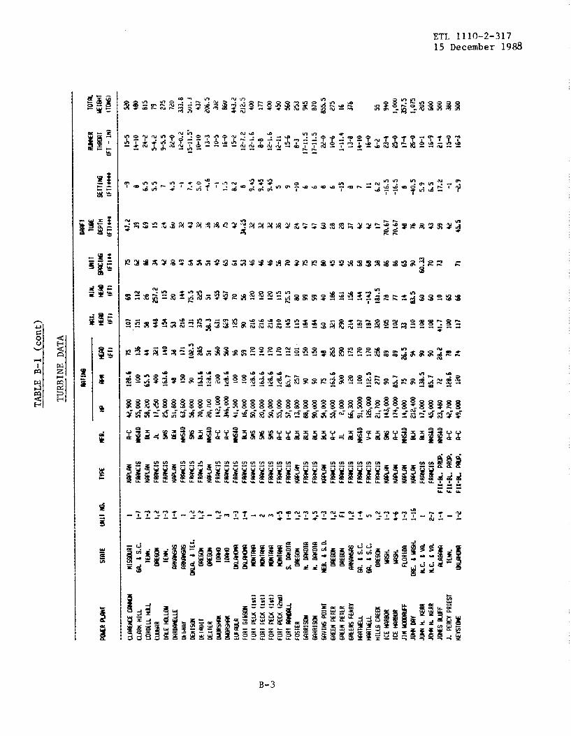
TABLEB-1
(cent)
TURBINEDATA
..._.—-
Mrlw
Ml
mx,
BIN.WI1
I@
-n
10IK
Wn
ml
SfnI
Ew
lrm
lYPE
*R.
wM
mm
wm
lw#l
nEI
TIN
SlH
~luE
lmT
(Fll
(FTI
IFT)
IFII*
*(F
l)m(F
I)*
(F1
-IN
)(lC
WS)
--.-
--—
.—
..-.
—
cLa
REm
-m
MIL
LW
HD
ELL
ML
CW
RW
EH
RLC
UW
WLL
EM
bFI
flVm
lwO
EIRO
I1O
ElIk
Rw
-M
RMEL
F~9
FORr
GIE
IWFO
RIPE
W[l~
tlFO
RIC
EW(ls
t)FO
RIKm
(lSt)
FORT
KM(?
ml)
FURI
_FO
STEF
IM
RR12
U4
WRR
IWW
lffi
PoIN
TG
REEN
FEIE
RG
MEN
PETE
RM
ERS
FEkR
YW
RIH
EI.L
WRI
UELL
H1L
L6C
REEK
ICE
WSO
RIC
Em
mJI
14~F
JMM
YJW
h.KE
RRJM
H,
NER
RJL
MS
SLO
FFJ.
PEKV
PRIE
ST
HEv
STM
s.W
OT9
DRE
WN
,W
TRN
.W
OIO
m.
1s.0
.O
EGO
No
REso
N
m.
tS.
c.
m.
JS.
c.
oRE
mm
.m FLO
RIM
ORE
.tw
N.C
.t
W.
N.c
.Lw
TEFu
4.
I 1-7
1-3
1,?
1-3
1-4 I 1,?
1,? 1 1,2 3 1-3
1-4 1 2 3 4-5
1-8
1,2
1-3
4,5
1-3
1,2 F1 1,2
1-4 5 1,2
1-3
4-6
I-3
1-16 1
2-7
1-4 1
kcU
,900
128.
6W
D55
,WIU
JRl
i58
,200
65.5
JL17
,250
400
w25
,000
163.
6M
uSl
,so
o4s
MIL
I63
,WIw
w56
,000
90SL
li70
,Oc
Q16
3.6
MtD
20,/
@12
0.6
H14
2,00
0Zw
a-c
34b
,W1c
8.6
MtD
41,5
0010
0M
16,W
I@Sn
s50
,000
120.
6SN
s20
,000
163.
69s
50,0
1Y3
128.
6H
55,0
00ltS
.6H
57,0
00SS
.7SL
Ei13
,s00
257
SLH
EL9,
m90
m9D
,000
90E4
.H54
,W75
F4-c
55,0
0D16
3.6
JL2,
000
900
Rtl
66,3
0012
0W
\D
91,5
000
10D
v+12
6,m
11?.
5SL
H21
,700
277
SNs
143,
000
90a
-c17
4,00
0S5
.7N
D14
,~75
M21
2,40
090
KH17
,000
138.
5W
LD45
,DO
005
.7-O
23,4
S071
?k?
-c42
,7W
120.
6
w49
,Wla
75 136
44 UI 14
0M 17
110
2.s
2s5
51 560
560
% 59 170
140
170
170
112
101
150
150
40 265
290
17s
170
170
256
89 89 26.5 94 90 90 2s.
270 74
107
151
5s 446
154
53 216
131
375
5s.3 63
1&
9 125
90 216
216
216
210
145
115
184
IM 60 321
290
?14
167
167
320
105
102
33 110
10s
10s
41.7 lw 11
7
69 112
?6 257.
211
520 14
475
.522
551 4
s5 457
70 % IN 120
120
115
75.s
so 99 S9 40 I& 161
156
144
-143
181.
578 n 14 S3.5 60 w 10 65 66
75 62 S6 34 42 w 49 64 54 51 45 65 61 53 46 46 46 56 70 40 75 15 so 45 45 56 6s 6s 3s S6 S6 65 90w
.33 70 73 71
47.2 39 69 15 24 6U 32 43 32 * 36 75 4i?
34.2
5w 32 32 36 * 24 47 47 60 ;8 20 37 4d 42 17
70.6
770
.67
4s 76 30 43 59 * 45.5
-9 e 6.5
5.5 7 4.5 -1 7.+
5.0
-4.6 -1 1.5
b.2 0 9.45
9.45
9.45 5 9 -10 6 6 8 6 -15 a 7 11 6.2
-16.
5-1
6.5
8-4
0.5
5.9
6.5
17.2
-1 +.9
15-5
14-1
024
-25-
4.1?
9-5.
522
-012
-0.L
?15
-11.
5’1o
-1o
13-3
10-5
16-0
15-2
12-7
.212
-1.6
8-0
12-1
.612
-11
15-6
8-3
17-1
1.5
17-1
1.5
&-o IO-6
1-11
.413
-814
-10
16-0
6-2
23-4
25-D
17-4
26-o
10-1
16-9
?1-4
15-0
16-J
520
4s0
615
79 275
720
333.
851
J1.3
437
m.
530
?S6
u44
3.2
?12.
540
017
740
045
0
560
253
945
870
2.55
.527
516 J7
6
55 9+0
1,00
035
7.5
1,07
5m 60
050
03s
0w

TABLEB-1
(cent)
TURBINEDATA
-.--
.——
—-—
——
——
——
-—
—.
..-.
—-
——
Ml
IwW
T—
.—
MI.
MIN
.M
ITlK
-RTO
TW
Wrl
WI
SIA
IEW
Ir
M30
Trr.t
*R.
@m
m-
wm
lwEP
rnsr
llffi
Iwr
Klm
r
(Fl
I(F
TI(F
TI(F
T)**
IFT)
***
(FIJ
**tt
(FT
-IN
I(I
wl
.---
_-_-
_—
---
_—__
_-—
—.
—--
LWL
LIBb
VLl
kBY
LIIIL
EU
LllrL
EW
Loo
Kwr
mlN
rLO
STLR
EEK
LKR
6RW
IIELW
RG
RWIIE
LWR
NO
NU
NEN
rkLO
UER
MN
rmW
RYfU
,NF4
RV
WRY
MIL
LERS
FERR
VW
ILRI
VER
WIL
RIV
ERW
RMW
RRW
NEW
KLM
S
mR
FoN
K
M OLrl
tiIw
oR
v
olf
lKu
fwlL
lfflT
rRI
WRD
b,
mFi
Vb
ERTS
.KE
RRW
INT
MRV
S(W
O)
WIN
IM
RVS
(MK)
S81N
rM
RYS
(MEN
)W
INI
SIEL
Ww
Mvw
fwSN
Ellls
wSN
ETTI
WSl
~KllJ
NT9
SLE
mlE
NKI
LLER
FERR
Y
r~us
HEN
IWY
wrm
MN
lmW
SN.
w.
uREL
iiJN
URE
Ww
.m
sN,
H.
U4s
li.O
RE.
tb
K4sN
.O
RE.
tH
.O
RE.
1w
km MI
WE
I
oRE
mN
1 1-4
5-8
1-3
*-6
I-3
1-r?
1-3
4-6
1-3
4-6
1-12
13,1
4SS
{2J
1-3 1 2 1,2 3 1,2
1,2
1-7
1-4
1-5
1,2
1-4
1-4 10 1-3 & 1,2
1,2 3 1 1-4
1,2
1-14
SNs
SNs
ao
vEw JL v-
Ra
-cR-
c
o-c
w $tc
R-c
9a,W
o14
416
5,00
012
8.6
165,
W1?
8.6
21?*
W90
21Z,
UU
090
52,5
U0
128.
633
,auo
?40
211?
,4u0
9U21
?,40
090
212,
400
90?1
?,40
0w
11
1,3
00
65.7
111,
300
65.7
4,50
021
734
,000
69.3
wlW
IM.8
w12
,000
225
12,m
225
205,
000
163.
642
,000
ldB.
612
8,50
010
045
,m7s
27,w
60.Z
9,40
027
710
4,W
la3a
,Oo
o75
J,U
o12
8.6
6,97
5b
o3,
w12
8.6
39,0
0010
041
,m12
0R’
BIW
I32
,300
514
02s
47,W
o6C
QM
to71
,atx
l75
EE&
l62
,ouo
128.
6M
o23
,W15
0u
123,
ao
oa
5.7
231
300
3U0
93 93 la5
215
9J 93 9+ 9+ ao
au
ao
35.5
m.
om
.o
132
132
460
160
la5
45 ?1 Iw 144
29 20 21 21 49 70 745
945.
s81 19
013
281
255
341
341
9a 9a 233
323
100
100
100
106
92 9? 92 41 m.
o20
0,0
153.
515
3.5
5a5
202
203
60 35 176
162
47 22.6
22.6
22.6
57.9
aa 900
990.
510
22c
b18
190
,5
214
165
165
90.5
w.
512
619
476 76 67 87 b2
Q 62 25 225.
022
5.0
% 9a 302.
513
011
423 17 13
420 1.9.
318
.318
.340
.353 67
57a
a46 13
410
3.5
60
63 63 w w 60 36 w 90 90 90 a6 66 27 M
200.
020
0,0
32 32 54.5 54 76 60 65 32 71 87 28 54 49.5 57 26 26 N
IFI
5+ 44 &
33.5 42 k 76 76 33 24 76 76 76 76 59.5
59.5 s 60 18 10
3a.2
332 44 60
39.?
016
.543 b
l21
.236
.33
27.S
356 45
.5 13 1370
.67
G 30 70.7
0 -1 -1 -39
-39
11.2
-0.5
-4I
-41
-40.
5-4
0.5
-a.5
-0.5 -4 11.5
9 9 7.5 10 4 8
-14.
73.
7 1? 7.5 5 3.23
+.27
-10.
4*-3
.5-2
.0 -8 -6.5
7,2
7,9
-16
13-3
.114
-IV
1+-1
026
-o26
+13
-0.a
7-1o
26-O
26-0
26-0
26+
23-4
23-4
5-3.
622
-31-
4.5
1-10
6-9
6-9
12-2
12-1
.617
-022
-o26
-35-
5
24-2
9-6
IW 9-2
]a-6
15-0
4-3
4-3
23-4
.613
-69-
b.1
23-4
4aa
w.
55U
2.5
1U75
la w.
5I&
.5
1,07
51,
2W1,
075
l,&A
I,ow
I,ow
50 550
2.7
7.3
a7.
3
87.3
33s.
o74
0.5
055.
574
570 67
5
293.
014
655 b
oo
326
247.
51,
025

TABLEB-1
(cent)
TURBINEDATA
...
.--—
.——
——
——
mllw
Ml
mx.
RIM
.Im
llTM
-RTO
Tm
WR
ml
Slfil
EW
ITm
l.IV
K*a
.w
m-
wm
mlM
3o
EPrn
*111
*W
rW
lrnl
(FI)
IFIJ
(FT)
(FTI
**IF
llwt
(FTI
**os
(FT
-IN
)(lWI
——
----.
—-.
--
Iwd
l?Fl
,F2
Ssl?
)1-
21-
4 1 1-3
2;3
1,2
1-6
lqo
oo
18,w
4,5U
0*O 45
,500
177
30,9
005,
w51
,500
20,7
(JO
62,m
do
m 217
163.
611
2.5
257
W.
2432
1I@ 12
a.6
105.
9
73 74 al
21.1 70 15 22 77 5a 91.5 16
0
90 da
90.5 32 82 30 31 71 72.4 1?
621
4
5a66
5540
60i7
11.5
25
3767
5N
/O17
6544
M/a
4477
77.5
46Ill
5a
70,7
-14
35.5
-14.
550
.3-5
.515
.44
5
4s.
5-2
.53.
76-1
4.a
la-2
.0%
-1.1
30a
.53a
7
25-o
10+
5-3.
5S-
2.1?
16-a
26-3
6-O
19-2
10-1
0.8
lW.5
sa9
167.
542
,5 378
745
17.5
437.
51M
7.5
557.
5
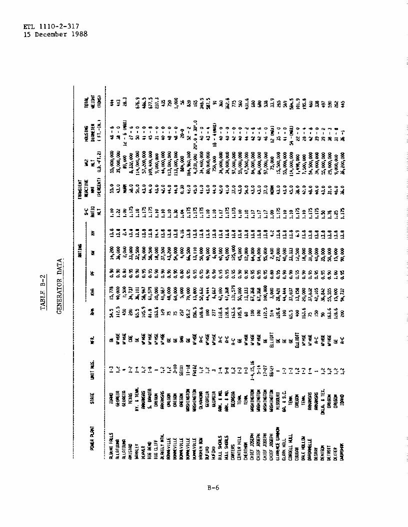
TABI,EB-2
GENERATORDATA
W
mT1
wlM
IEN
T..—
—s-
cW
TIV
Ew
WIN
GTo
lu
KX4E
Rm
lST
filE
UNlr
w.
*R.
WKV
RW
UN
KVrm
rloW
IN
rO
IWTE
RU
Elw
rU
T(w
RcfN
l)(L
2.+1
.21
(FT
.-l
N.
)(lW
J..
—--
--—
---
_——
-——
——
-
1-3
1,? 4 1-2
1-4
1,?
1-8 1 1,2
1,2
3-1o
Ss(o
)
II-1a
Ful4
21,
21,
2 3 1-4
5-8
1,2
I-3
1-3
I-4,
15,1
65-
14
17-2
7SS
(2)
I 1-7
1-3
1,2
1-3
1-4 1 1,2
1,2
1,2
1,2
54.5
1$77
011
?.5
40,L
n)o
450
i,50
0
U?
2H:
11J5
,9*9
4701
.861
,579
163.
6W
,000
120
41,%
715
4e,m
7560
,000
257
qo
oo
69.2
70,0
00
1%.s
13,E
14M
)12
8.6
52,W
100
44,4
4427
76,
667
128.
642
,100
128.
647
,M]6
3.6
131,
S79
105.
950
,000
6013
,333
100
67,3
SS10
067
,36S
112.
510
0,00
0s1
43,
1m)o
12&
628
,421
100
44,4
446s
.s37
,1)3
740
013
,15s
1630
620
,~7s
37,6
32Iw
42,1
05w
3S,8
4216
3.6
S5,S
S512
8.6
IS,
Ww
94,7
37
0.w
0.90
0.w
o.9
s0.
900.
9so
.so
.%o
.w0.
900,
w0.
00o
.%0.
950.
950.
900.
90
0.9s
0.9s
o.9
s0.
900,
so0,
950.
950.
950,
ao
o.%
0.90
0.90
0.55
0.9V
0095
0.95
0.9s
o.w 1.00
0.95
14,2
0036
,000
2,w
33,0
0032
,500
5s,w
*m 18*W
37,5
004
4m
n,
Ooo
4,m
66,w
13,1
10so
,m40
,000
6,00
Q40
,m4$
000
la,
Oo
o4$
000
12,0
0064
,w64
,000
~oo
o2,
400
27,0
0040
,Oc
il33
,333
12,s
0018
,w31
,000
40,0
00
35,0
0050
,000
lS,0
0090
,000
13.8
13.8
2.4
13.d
13.8
13.b
13.8
14.4
13.s
13.8
118
4.16
13.e
13.8
13.8
1300
13.8
13.6
13.6
13.e
13.8
13.0
1398
13.e
13.6
4.2
13.8
13.a
13.8
6.9
13.8
13.a
13.8
13.8
13.8
13.8
13.a
1.10
1.2.
21.
001.
175
1.10
1.17
510
1?s
1.10
1.10
1.10
1.30
1.04
1.17
s1.
175
1.17
51.
101.
101.
171.
175
1.17
51.
101.
101.
171.
171.
17lo
w1.
175
1.10
1.10
1.17
51.
101.
17s
1.17
51.
s01.
761.
251.
175
55.0
43.0
d.
oS1
.o43
.044
.043
.042
.044
,044
.00.
30u,
o45
,041
.043
,044
.0u
.o
41.0
S7.o
43.0
S4.o
43.0
43.0
37.0
NO
M43
.043
.04s
,o3s
.o42
.04s
.o40
,043
.0
31.0
46.0
36.0
5S,W
,000
4S-6
39,0
00,O
ov
M-o
09,0
001?
-6(W
X)
6,33
2,w
27-6
114,
0V0,
000
w-0
57,w
,w
41-O
109,
400,
000
45-8
9,00
0,U
oo
31-0
44,0
00,0
0040
-011
3,00
0,m
48-0
113,
000,
000
40-0
M4,
m20
-0
lM,9
60,0
4kl
52-2
4,23
1,00
020
t.0E
M’.
O34
,400
,W40
-0So
,ovo
,Oo
o43
-47s
0,O
vo18
-4(
WX
)34
,Vo
o,O
oo
40-0
34,0
00,m
4L)-
O97
,000
,000
42-O
5s,O
oo
,w40
-0
47,5
00,0
0044
-2
B4,W
,000
42-6
L44,
000,
000
42-6
97,0
00,W
46-O
7s,O
oo
12(m
l)15
,SO
0,00
03s
-0Ss
,000
,000
41-0
114,
m,o
oo
54-(
mx)
1,4’
3S,0
0022
-o7,
Soo
,Oo
o26
-454
,500
,000
42-
a34
,000
,000
39-o
S5,0
00,0
003s
-229
,000
,000
3s-3
9,m
,O
oo
31-8
*200
,000
3s-1
444
413
2s.
3
676.
94s
6.s
677.
523
7.3
435
750
I,oo
o56 w 16
534
8.s
SS7.
s91 36
0u.
b77
sw 43
1.6
w 680
53s
33.9
265
569
5s4.
510
I.919
5,8
460
33s
497
S90
2s2
445

TABLEB-2
(cent)
IOa9
13
1-3
1-4 1 2 3
b-5 l-a 1,
21-
3 4,5
I-3 1,
2 FI 1,2
1-4 s 1,2
1-3
4-6
1-3
l-I6 t
2-1
1-4
5-8
I-2 1
1-+
s-a
1-3
4-6
1-3
;-~
1-3
4-6 1-
34-
6
1a6
231,
572
Iw31
,579
100
1?,5
n12
8.6
*W9
164
1466
712
S.6
~M9
12s.
642
,10S
6142
,Ius
2s7
lq52
690
24,2
1090
64,2
107s
q10
016
3.6
42,1
0sw
1,s0
012
0S0
,326
100
?&3.
U11
2.s
M,2
1O27
7Iq
169
w94
,737
25.7
Il&sw
7s11
,111
9014
2,10
s13
s.5
1433
36.
7%
sss
1217
,s9s
12s.
731
,111
120
%64
214
467
,779
12S.
611
0,S2
612
S96
110,
S90
142,
10s
wIu
,10
s!2
S.6
47,2
2224
0&
7b9
90I%
105
w14
2,10
s
w14
2,10
s
90l%
la
o.% afi
a90
O.m
O.w
O.w
0.9.
a% o. 9
s0.
%a
m0.
%a9
s&
%b% o
.% a% 0.9s a9
so
.% a90
a% an 0.90
a9s
0.90 as
s0.
90 a9s
o.% ass a9
sa9
sas o.
%o.
%a9
sas
1.17
s1.
17s
1.10
1.10
1.26
1.10
1.17
1.17
i.in
i.% 1.17
s1.
17)*
17s
1.in
1.%
1.17
s1.
171.
175
1.17
si.
17s
1.10
1.17
s1.
17s
1.17
s1.
I&i.
101.
17s
1.10
1.17
s1.
17s
1.17
s1.
to1.
17s
1.17
s1.
17s
1,17
s10
17s
39.0
44.0
4%0
3%0
*O u.o
42.0
46.0
42.0
34.0
43.0
Wo
4ao
41.0
u.o
4L0
4ao
43.0
32b
4S3
.o43
.04L
o4%
0*.
O
*O &o
4ao
4ao
4ao
4L0
Qo
42.0
3s00
43.0
43.0
4380
43.0
2U0,
0U0,
000
*-3
31,9
00,0
0039
-2l*
SOD
,W2s
-030
,000
,000
*+
7,00
0,00
02S
-630
,000
,000
36-0
m,q
ouo
3s-4
U,o
oo
,ao
ou
-02,
0U0,
000
17-1
1122
-10
l*O
OO
,OD
Ow
-61~
000,
000
W-6
S0,2
00,W
47-1
022
,000
,000
32-
eq
3so
44-o
40,q
oo
o38
-0
%W
oo
o44
-0n
,614
,011
044
l,so
o,o
lm21
-b1*
*000
49-o
-*W
~+
20,0
00,0
0037
-10
(w)
245,
W,W
S4-0
7,SO
0,0(
I031
-a60
,000
,W42
-630
,400
,000
69-4
28,0
u0,0
0036
-630
,000
,000
3s-2
4400
0*00
039
-a
9?*S
O0,
000
41-0
24,3
62,0
0045
-o24
qw
,oo
o54
-034
1,00
0,00
0S4
-0*
4so
,oul
37-o
7,Io
o,o
oo
244=
-024
%00
0,00
054
-024
1,30
0,00
0S4
-024
$~00
0S4
-024
1,q
oa
lS4
-0
921
345
226.
sM 16
sm 41
t.461
411
s.s
1,12
2.s
m 631.
434
2.5
342.
s42
461
S
113
1,01
3
267.
51,
I*.O
170
S12.
Sm 31
040
1.s
421
553
W2
i,16
11,
176
4s4.
sIa
s1,
161
I,i7
61,
161
I,17
6

TABLEB-2
(cent)
GENERATORDATA
—.
.-..
-—-.
.--
-——
-—M
llwTW
IEN
T—
.—
s-c
Erlc
llww
Nln
rslff
iTo
lm-R
ml
SIRI
ELm
irm
s.W
R.W
*KW
WKu
Rvm
rloM
Tm
lD
l~IE
RW
1ON
1
Ki(K
~N
l)(L
EI.
~T
.2]
1FT
.-l
N.
)(T
om
)--
-.--
----
.——
.-.-
——
___-
——
--—
-—
-—
—-—
...—
——
-.—
—
wRf
WW
RYN
LmRv
141LL
ERS
FERR
YW
ILRI
WR
~lL
RIV
2RW
RRO
HS
W*
MN
MLM
Sm
omw O
LDH
IOU
WIV
O1O
RNRI
LWD
B.RU
SSEL
LRO
EIER
IS.
URR
Saiti
rm
TRvs
(uLo
)24
T1r4
rWRV
S(K
u)M
INr
Wvs
(Mu)
WIN
rSI
EMW
wrm
YsLI
RNxr
rl~W
rllm
slur
mTW
E~
rEN
RILL
ERFE
RRY
IWC
41LL
ESI*
mLE
slt4
EW
L2S
ltEus
TUU
4KW
FW
IER
F.SE
--L
LoW
E6ER
SFm
LSus
srra
[Nr
UES
Iw
174T
14H
Irwv
~FC
REEK
I-12
13,1
4SS
(2)
1-3 1 2 1,2 > 1,2
1,2
1-7
1-4
1-5
1-4
1-4 10 1-3 h 1,2
1,2 3 1 1-4
1,2
I-14
15-2
2F1
,F2
SS(2
)1-
21-
4 I 1-5 1
2,3
1,2
1-6
GE
EE!r Efi
u’% *J *J
ELLI
OT
u’M SE u’E w SE SE Sil
SE E SE SE MlH SE
SIEN
ENS
E u’m
EEL
LIor SE S2 u’w EH C6E
ELLl
or
SE w SE o-c
SE
6s.
165
.1 277
69.3
lM 900
225
225
16.E
.6
128.
610
075 51
412
07s 1C
806
so 128.
6
120
514
600
75 1?8.
615
005
.1 20
200
27?
163.
611
2.5
514
21 100
120.
61U
5.9
73,6
s473
,664
3,75
026
,316
w I,& 9,44
49,
444
166,
U7
36,6
0989
,474
31,m
21,0
5370
,947
26,9
472,
w5,
3.33
2,50
0
21,w
26,2
0034
,500
47,5
79*,
w17
,855
u,10
590
,500
14,2
103,
750
4,44
4
36,1
11
21,0
533,
750
36,8
4216
,667
50,O
uo
0,% 0.95
0.20
o.% .8 ,8 0.90
0.90 0.90
0.90
0.95
0.so
0.95
0.55
0.95
0.s0
0,90
0.80
0.95
0.90
0.90
0.95
o.%
0.95
0.95
0.95
0.95
0.20
0.90
0.9U
00%
0.90
0.95
0.90
0.w
10,0
0070
,000
3,m
a,
Oo
orb 1,33
3a
,w El,5
0015
0,00
035
,000
65,m
25,0
0020
,000
75,0
1xl
27,5
002,
W4,
w2,
m
26.0
0023
,560
31,0
5045
,200
50,0
0017
,W76
,m65
,95
l&50
03,
W4,
000
32,5
00
20,0
003,
375
35,0
0015
,000
4300
0
13.6
13.e 4.2
13,8 .42
.42
13.8
13.a
13.0
13.8
13.8
13.e
13.8
13.8
13.8
4.0
13.8
4,2
13.8
13.8
13.8
13.8
13.8
13.8
13,8
13.0
13.8
4.2
4.2
13.e
13.8
4.I?
13.8
13.8
13.e
1.90
1.90
I.CX
T1.
175
1.10
1.10
1.10
1.10
1.17
51.
001.
175
1.17
51.
175
1.4
1.10
1.00
1.17
5
1.0
1.1
1.17
51.
171.
171.
115
1.11
51.
175
1.00
1.10
1.10
1.17
51.
101.
175
1.10
1.10
2.0
Q.o
35.0
2.0
43.0
43.0
38.0
43.0
42.0
46.0
35.0
J7.O
49,0
24* 36
.636
.(J
44.0
34.0
34.0
41.0
41.0
44.0
44.0
44.0
43.0
mRN
31.5
43.0
&o
44.0
44.0
45.0
43.0
130,
000,
W
16S,
000,
000
w,O
oo
53,5
00,D
O0
d,4
004,
500
2,O
uo,m
2,00
0,00
0b
7,W
,0u0
30,m
,O
oo
165,
000,
000
70,D
oo
,Oo
o60
0,00
063
,W,w
61,W
,000
1,50
0,00
06,
7S0,
W1,
500,
W
20,7
00,0
001,
300,
000
l,m,
oo
o26
,w,
Oo
o40
,000
,000
8,5U
0,O
oo
136,
W,0
0016
3,00
0,00
02,
900,
000
360,
0U0
547,
m40
,000
,Oo
D
600,
w21
5,00
035
,200
,000
II,o
oo
,oo
o55
,000
,000
51-8
51-s
17-7
1m1)
43-6
22-o
21-0
4t+
3-4
4W 45-a
11-1
023
-344
-e16
-4a
-2 16-4
x-s
&-0
m16
-626
-OH1
7-0
46-0
30-0
??-3
50-8
50-4
d4-
716
-O(W
i)16
-7x1
4-4
36-o
11-1
015
-511
6-1
40-8
33-o
w
1,20
01,
165
50.5
430
24,6
50.0
33,0
75,0
95 91
3s6.
s22
6.5
559,
511
3.5
451
156.
562
.5
303
162
716
436
173.
5%
960
7.9
165
50,5
47.0
464.
5
113.
553
3.s1
.121
5.5
560

TABLEB-3
PUMP-TURBINEPERFOWCE
DATA
mllm
Mrlm
mK
.nt
tiW
.n
iw
mn
Plm
lsl
alE
Ml
1TW
E*k
mw
mw
mm
GF.
Rm
wm
{FT)
IFTI
{Fl)
IF1
)(F
l)(F
T)
.-—
.——
-
mlE
SSSE
oss
ia44
F~lS
WIw
ll&ooo
34s
427.
s32
04,
43s
341
327
21U
FIS
EU
-M
lssa
sll
2F=
lSN
n@
m7s
JO?
69$5
0060
60w
Uw
v2
F-IS
mSi
D12
8.6
44,m
171
216
144
I,w17
011
0Iw
TwFl
[@I
1-6
W.a
.lK
1..m
.u
100
*W42
.519.2
414,
mw
M44
.4
TABLEB-4
~UM
P-T
UR
BIN
EW
EIG
HT
SA
ND
DIM
EN
SIO
NS
c01
s1.
CD
IS1.
TOcD
lsT.
10lm
ll10
ml’f
ia
laT.
u,M
IN.
T.U
,-R
-nm
ERm
lS1
91E
WIT
T=m
lw(F
ml
1lu
llW
lmo
l-IM
.ET
TOTA
mC
lot
m-M
llmm
DI*
TER
OIW
IER
Klw
l(F
T)(F
IJ[F
l)IF
1)(F
r.-l
N.
)(F
r.-1
M.)
(IIN
S)
msr
Ess
Emln
44F~
IS63
2s-2
1.s
-21
14-2
20-8
797
mm
mH
ISSU
JS1
EFM
IS62
w-9
019
-322
-6.4
I,0J6
DE9
mv
2F~
lS49
32-J
-111
-3.8
Is-9
.532
IwH
iwl
I-6
W.
J2J.
.Jm
.S2
6S7
3s-3
0.4
-26
El-e
Wn
6s3.
s
TA
BL
EB-5
~TES
SSE
ons
ln3-
4m
1~13
1,57
90.
9slq
oo
o13
.t1.
17s
34.0
Iqoo
o0.
9s13
.890
,000
,000
651.
0m
asE
m-
MIS
SWSI
eST
s2&
42J
O.%
27,0
0013
.s1.
17s
42.0
40,4
630.
9s1A
5SJ
,w
,m4s
-04
32
.s
DE
WY
2n-
c12
S.6
29,4
74O
.%24
000
ILD
1.17
S33
.043
,240
0.9s
13.s
19,2
00,*
39-0
274.
0I-
Mlu
lI-
6E
102s
,mo
.%~%
713
.B1.
17s
4%0
*W0.
9si3
18*o
oo
,m40
-032
s.0

ETL 1110-2-31715 Dec 88
APPENDIX c
‘IURBINE S_ION CHARTSAND D=SIONS
mm PAGE
1 FRANCIS TYPE TURB~ , ~ E3?FICI~CY c-3AND PHI, SPECIFICSP~ VS. HEAD
2 FRANCIS TYPE PUMP-TURB~ , RATEX)PUMPING c-4~ITIONS , UING HEAD VS. SP=IFIC SPEED
3 PROP- TYPE TURBINES, RA~ ~ITIONS , c-5SPECIFICSP_ VS. m
4 FRANCISTYPE TURBI~, D-IONS AND C-6PROPORTIONS
5 PROPELLER TYPE lWRBINES, D-IONS c-7
DATA AND DmIW RATIC6- ~=1.o
1 -CIS TYPE ‘iURB~ c-9
2 FRANCISAND PROP~ TYPE TUFU31NES c-lo
3 FRANCISTYPE PUMP ‘IURB~ C-II
4 PRO~ TYPE TURBINES C-12
5 PROP- TYPE m= C-13
c-1

ETL 1110-2-31715 Dec 88
c-2

ETL 1110-2-31715 Dec 88
1001..J.–_,...A..,. .——---,—+~~ J —-4 —--+...—A.._.—........t......
, , ! ,, ,,-. -J.. ., —------- +..
mz“ ~n~ .-_{..-.+ . . . . .. -. f— .—4–- .- t-. + ~-t--J
30
15
In,“-—
60 80 100 150 200
HEAD IN FEET
300 400 500 600 800 1000
Figure 1. FRANCIS TYPE TURBINES
BEST EFFICIEfiJCY AND PHI
SPECIFIC SPEED VS. HEAD
c-3

ETL 1110-2-317
15 Dec 88
Note: Plotted points are from existinginstallations.
1000
800
zH
1000
Figure
1500 2000 3000 4000 6000SPECIFIC SPEED - N
‘P
2. FRANCIS TYPE PUMP-TURBINES
RATED PUMPING CONDITIONS
PUMPING HEAD VS. SPECIFIC SPEED
600
500
400
300
200
150
100
80
60
50
4010000
c-4

ETL 1110-2-31715 Dec 88
10 15 20 30 40 50 60 80 100 150HEAD IN FEET
FIXED BLADE RUNNER
300
mz
200
150
100
8010 15 20 30 40 50 60 80 100 150
HEAD IN FEET
KAPLAN (ADJUSTABLE BLADE) RUNNER
Figure 3. PROPELLER TYPE TURBINES
RATED
SPECIFIC
CONDITIONS
SPZED VS. HEAD
c-5
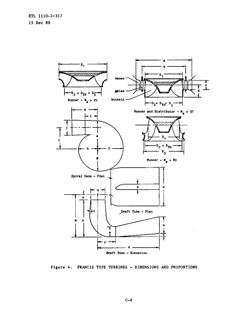
ETL 1110-2-317
15 Dec 88
1- “ 1,
buckets ~
b 2 a ‘Tti‘3-1
t-;a w
Runner ●nd Distributor - N~
A
k— n ------1Draft Tube - Elevation
= 37
Figure 4. FRANCIS TYPE TURBINES - DIMENSIONS AND PROPORTIONS
C-6

ETL 1110-2-31715 Dec 88
Plan
a I
l“I ‘\I
Elevation
-ctionX-X
Figure 5. PROPELLER TYPE TURBINES - DIMENSIONS
c-7

ETL 1110-2-317
15 Dec 8851.543
~
&L11.0>
z
G-i-5CAz~oo5
5L4>
5H4 0B 30 40 50 60 70 80
WATER TEMPERATURE - ‘F.
Figure 6(a). WATER VAPOR PRESSURE VS. WATER TEMPERATURE
Figure 6(b). BAROMETRIC PRESSURE VS. ELEVATION
C-8
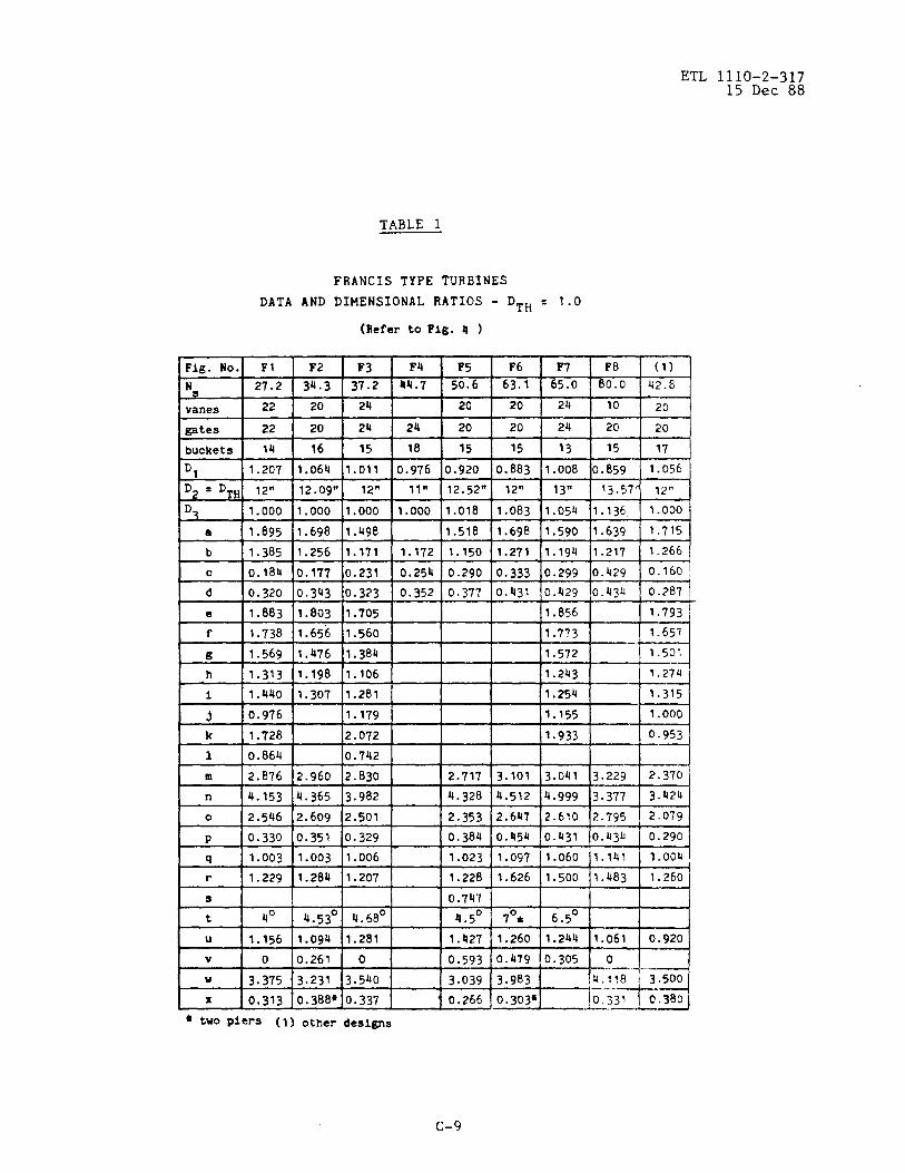
ETL 1110-2-31715 Dec 88
TABLE 1
FRANCISTYPE TURBINES
DATA AND DIMENSIONAL RATIOS- DTH = 1.0
(Refer to Fig. 4 )
gates I 22 I 20
buckets I 14 I 16
a 11.895 [1.698
b 11.385 11.256
c 10.184 10.177
*
d 0.320 0.343
e 1.883 1.803
f 1.738 1.656
g 1.569 1.476
h 1.313 1.198
i 11.440 11.307
-
3 0.976
k 1.728
1 0.864
m 2.876 2.960
n 4.153 4.365
0 12.546 12.609
P 0.330 0.351
v i O 10.261
F3 F4 F5 F6 F7 F8 (1)
37.2 44.7 50.6 63.1 65. o 80.0 42.8
24 20 20 24 10 20
24 24 20 20 24 20 20
15 18 15 15 13 15 37
1.011 10.976 10.920 10.883 11.008 10.859 I 1.056 ~
12” 11,1 12.52n 12” 13~ 13.57’ 12”
1.000 1.000 1.o18 1.083 1 .05ti 1.136 1.000.
1.490 I 11.518 11.698 ]1.590 11.639 I 1.715
1.171 1.17211.150 11.271 [1.194 /1.217 1.266
0.231 0.254 0.290 0.333 0.299 0.429 0.160 ~
0.323 0.352 0.377 0.431 0.429 0.434 0.287 I
1.705 1.856 1.793
1.560 1.773 1.657
1.38u 1.572 1.501
1.106 I !.243 1.274
1.281 I II 11.254 I / 1.3151
1.179 I II 11.155 1 I 1.000 I
2.501 i I 2.35312.64712-610 12.795 I 2079 I
0.329 0.384 0.454 o.h31 0.U34 0.290
1.006 1.023 1.097 1.060 1.141 1.004
1.207 1.228 1.626 1.500 1.483 1.260
0.747
4.68° 4.5° 7°* 6.5°
1.281 1. Q27 1.260 1.244 1.o61 0.920
01 I 0.593 /0.479 10.305 I o I I
3.540 ~3.039 ~3.983 14. I!8 i 3.500
-i-d
—..— ..0.337 0.266 0.303* 0.337 9.380
..——● two piers (1) other designs
c-9

ETL 1110-2-31715 Dec 88
TABLE 2
FRANCIS AND PROPELLER TYPE TURBINES
DATA AND DIMENSIONAL RATIOS - DTH = 1.0
(Refer to?ig. 4 )
FTopeller tieFig. No, (1) (1) I (1) (1) FB3 F(l) K(I)
N 48 50.8 57.6 65.2
=nes 23 20 20 10m m a
gates 24 20 20 20 ~ 5 5
buckets 13 17 15 15 0 0 0v- o- cl-
‘1 1.060 0.935 0.968 0.807 =- $ ~- < m- <
D~ = D~~ 13.72”12.52” 15.75” 14.87W WL QL. Q~
D3 1.000 1.018 1.022 1.081DC DZ D.cmu au -m*
a 1.600 1.518 1.542 1.580
b 1.239 1.150 1.164 1.190 m~ mb m~
c 0.267 0.290 0.317 0.403
d 0.402 0.377 0.399 0.441
e 1.797 2.199 2.774 1.998
f 1.636 1.989 1.962 1.796
~ 1.448 1.715 1.7o8 1.553m m
h 1.179 3 1.305 1.160+
wi 1.273 r c
1.523 1.458 1.333
J 1.205 a 1.310 a 1.587 1.467 1.377
k 1.386 - 1.577 - 2.215 1.62o
1
m 3.117 2.711 2.754 2.646
n 5.122 4.328 4.054 5.867
0 2.712 2.333 2.355 2.201
P 0.404 0.379 0.399 0.445
Q 1. Oou 1.023 1,024 1.08ti
r 1.536 1.228 1.270 1.831
B
t 6.9° 4.5° 5.3° 7.6°
u 1.276 1.238 1.095 1.149
v 0.313 0.593 0.522 0
u 3.272 3.039 3.860 3.307
x 0.321+ 0.266 0.328 0.3044
● Two piers F c fixed blade; K = Kaplan
(1) other des~na
c-lo

TABLE 3
ETL 1110-2-31715 Dec 88
FRANCIS TYPE PUMP TURBINESDATA AND DIMENSIONAL RATIOS - DTH = 1.0
(Refer to~ig. 4 )
,Fig.No. PT1 PT2 PT3 (3) (3) (3) (3)‘:p”(l) 2150 3200 4700 26OO 4500 2650 5100
vanes 20 14 10 20 14 20 10
gates 20 28 20 20 28 20 20
buckets 7 6 6 6 6 6 6
D1 1.604 1.317 1.154 1.493 1.135 1.459 1.o78
‘2 = ‘TH 9.995” 11 .205n 13.000” 12.328W 12.000J12.850’12.030”D 1.0001.0001.0001.000 1.0001.0001.000
● 2.369 1.832 1.810 2.254 1.712 2.101 1.701
b 1.876 1.479 1.423 1.785 1.346 1.712 1.342
c 0.221 0.289 0.315 0.264 0.334 0.253 0.336
d 0.434 0.399 0.385 0.433 0.385 0.409 0.392
e 2.159 1.855 2.050 1.967 2.005 1.919 2.oo4
f 2.010 1.703 1.887 1.831 1.829 1.784 1.829
6 1.826 1.521 1.690 1.665 1.615 1.620 1.620
h 1.570 1.257 1.394 1.435 1.316 1.388 1.325
i 1.699 1.381 1.455 1.501 1.494 1.470 2.524 ‘“
~ 1.039 1.071 1.212 0.923 3.351 0.921 1.214
‘k 2.647 1.607 1.682 1.622 1.247 1.000 1.666
1
m 2.823 2.853 2.690 4.329 2.598 2.353 2.b76
n 1o.525 3.893 3.700 5.640 4.610 4.747 3.698
0 2.382 2.473 2.286 3.863 2.209 1.940 2.035
P 0.441 0.380 0.40U 0.465 0.389 0.413 0.441
q 1.000 1.000 1.000 1.000 1.000 1.000 1.000
r 1.299 1.284 1.183 1.173 1.118 1.240
s 0.638 (2) 0.600
t 7° 10° 7° 6° 7.4° 7°
u 2.162 1.238 1.009 1.615 1.507 1.403 1.012
v 1.941 0.555 0.404 0.470 0.623 0.903 0.389
u 3.838 3.094 3.63o 1.615 3.429 3.600
x 0.485 o.309@ 0.269* (2) 0.312 0.424~
(1) Gpmtits ●t e ; (2) No pier, ● s horizontal leg b circular.Max .
# Tvo piers ; (3) other designs
C-II

ETL 1110-2-31715 Dec 88
TABLE 4
PROPELLER TYPE TURBINES
DATA AND DIMENSIONAL RATIOS - DTH = 1.0
(Referto Fig. 5 )
z1) (1K F-27
10 24
20 24
4 5
FBI I FB2 I FB3
*
K1 K2 K3
10 20 20
20 20 20
4 5 6
10 I24I2O
bvanes
gates
blades
20124120 “24
5
12.44”1 12N 112.08’ 12.4Uq112.51n! 12N 12.44”1 12n 12”
FD -mode
a
b
c
d a1.571 1.443 1.542
1.194 1.148 1.192
0.482 0.394 0.404
0.427 0.367 0.365
0.327 0.350 0.327 s1.578 1.501 1.567
1.193 1.151 1.200
0.482 0.390 0.406
0.427 0.370 0.368
0.327 0.400 0.440
1.571 11.477
1.194 11.178 1.148
z0.482 0.406
0.422 0.368
0.360 0.390
3.062
0.855
0.394
0.367
0.350
2.911
0.787
Ie
3.00012.911 1-- I I 3.171bf
t2 I I 0.857
0.248 I0.300
1.854
1.515
3.o6o 3.127 3.171
1.4o6 0.875 1.457
0.248 0.251~ 0.257
0.268
1.671
3.020 2.907 5.030
3.900 4.391 3.930
1,170 1.323 1.220
0.275
1.780
1.318
2.912
m
0.236
m
s
m3.627
1.130
1.102
1.800
1.467
3.060 3.307
0.855 0.889
0.248@ o.321~Ek
1
m
n
3. Ooc
=
2.912 3.251
1.338 1.415
0.236 0.431
0.325
1.534
2.790 2.791
3.627 3.730
1.130 1.231
1.102 1.139
0.818
0.273
0.269 I0.227
1.566
2.773
=
2.780 2.9 6
4.o6o 4.529
1.280 1.303
1.240 1.333
4.500
1.174
1.424 w *
0.659
7°
● two piers; F = fixed blade; K = Kaplan
(1) other designs
C-12

ETL 1110-2-31715 Dec 88
TABLE 5
DATA
PROPELLER TYPE TURBINES
AND DIMENSIONAL RATIOS - DTH = 1.0
(Refer toFlg. 5)
(1)* (1) (1) (1) (1)
Ident. K F-29 .6* K K Fr
-nes 20 24 24 24 20
gates 20 24 2ti 24 20
blades 5 6 6 6 8
Dm-model 12” 12W 12” 12” 12”
a 1.574 1.443 1.443 1.443 1.500
b 1.200 1.14.8 1.148 1.148 1.200
c 0.406 0.394 0.4b6 0.446 0.409
d 0.368 0.367 0.394 0.39Q 0.551
e 0.350 0.440 0.440d
f 2.911 2.911 -- --
g 0.787 0.787 ; ‘. ; ‘.. w .
h 0.275 0.275 ~~ ::H v
1 1.780 1.78o a ual
~ “w u
1.318 1.318 ~~ ~~
k 2.912 2.912 2.892 3.394
1 1.338 1.338 0.787 1.457
m 0.236 0.236 0.266~ 0.480
n 0.325 0.325 1
I o I I 1.534 1.534 I I I In 13.030 I 2.780 [2.807 !2.628 13.028 1- {
r Q ]3.930 I 3.62713.627 I 4.063 ]4.414 ! I II I-.-— -.—. -—. , , J
r 1.220 1.130 1.130 1.221
s 1.200 1.102 1.102 1.137 1.326
t 0.720 0.659 0.659 0.545 0.780
u 7° 11° 4.6° 7°L# two piers; F = fixed blade; K s Kaplan(1) other designs
C-13
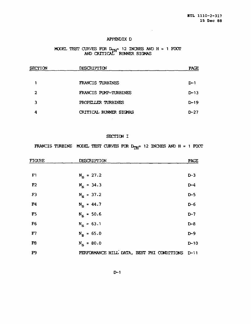
ETL 1110-2-317
15 ~ec 88
APPWIX D
MoDm TEsrcuRvEsm
*=121NmANDH=l FWI’
AND- RUNNERSI~
1 FRANCISlURBINES D-1
2 FRANCISPUMP-m= D-13
3 PROPEKIERmm D-19
4 CRITICALRUNNERSIQ4AS D-27
-ON I
mCISmINE MODEL~CURVES FOR~=121NCHES AND H=lm
FIGURE D~FI’ION PAGE
F1
F2
F3
F4
F5
F6
F7
F8
F9
N~ = 27.2
N~ = 34.3
N~ = 37.2
N~ = 44.7
N~ = 50.6
N~ = 63.1
N~ = 65.0
N~ = 80.0
-RMANCE HIU” DATA,= PHI CONDITIONS
D-3
D-4
D-5
D-6
D-7
D-8
D-9
D-lo
D-11
El

ETL 11+~-2-31715 Dec 88
D-2

XTL 1110-2-31715 Dec 88
0.
0.
0.
o.
0.
0.
12
10
08
06
04
02
0
0.50 0.55
Figure F1. MODEL TEST
0.60 0.65 0.70
0TH
DATA - FRANCIS TURBINE
‘TH= 12” ONE FOOT HEAD N~ = 27.2
D-3

m lllo-2-x715 Dec 88
&“x
0.
0.
0.
# 1 I \ 1 I % I+ UI
- -— --- -—- -~—
—7
/
-–— .-+- .—. . . . . .
t
.&. +.._— -+- -t-tI , ,,, 1,,
0.60 0.65 0.70 0.75 0.80
0TH
Figure F2. MODEL TEST DATA - FRANCIS TURBINE
‘TH= 12” ONE FOOT HEAD N~ = 34.3
D-4

ETL 1110-2-31715 Dec 88
.&x
o*
o.
0.
0.
0.
0.
0.
0.
0.
0.
0.
0.
0.
0.
0.
0.
134 ‘
‘‘.%‘J.—.-d<12 i A ..
11
L L_jJ.w#,”#+AQ
_____...7
:-+--+-T +%- F ---09+—_—. -————
EJ:5F=7!-. -— .—.—A— ...—+...—..-.--—
08
!.7 -—. — .J. A — —.
‘-~_,l-~,:,]-- -:_- ;:2.-..—.— -L——--–+.–– -– ..+ --- –.- +-- ~-- —-——–-—-—
07 I~--–.-~ –-.’
i ...~... ......;__’ ~ ;
06r ._.:+.:._-__+_< Z-:$.zxl:;..-_
~:.-:..__ ‘
j::“%-: :- ---;L— ..—–_---t— -— -“ —.—It /------ ~
aJ -so*-.-. -..—. -+... _ .
t-–.— -—.–———–—–— ————.?--.:-:11;---- ~:-_q-=== ‘--
-L------ --,.———..- ...—k—-- --------- ---— -.--4;:-~- ::~”?? ------’
05’t-––—- -1—...—.—–--- —-—–—-–— -—
k--— —.—. —...—
04j
03
——a-._ ..—— —._.———-.———._——.—— .—..— . —— .-——.--———-—.--- —— *—..-+
01’—.-———..——+.-...+..——_- F-~—— .-.-——. ..——1, T, ‘ “~og:j—- .- —.. —----.——.—.- L_— 1 ! .—t~- , .——-—.+——.76%‘! ;~i ! ;— : __L _,_:_.._
.-.=4 ~ -1.. —..—.... .——..-
0’,, ,’
0.65 0.70 0.75 0.80
OTH
FigureF3. MODEL TEST DATA - FRANCIS
‘TH= 12!! ONE FOOT HEAD
D-5
0.85 0.90
TURBINE
N~ = 37.2
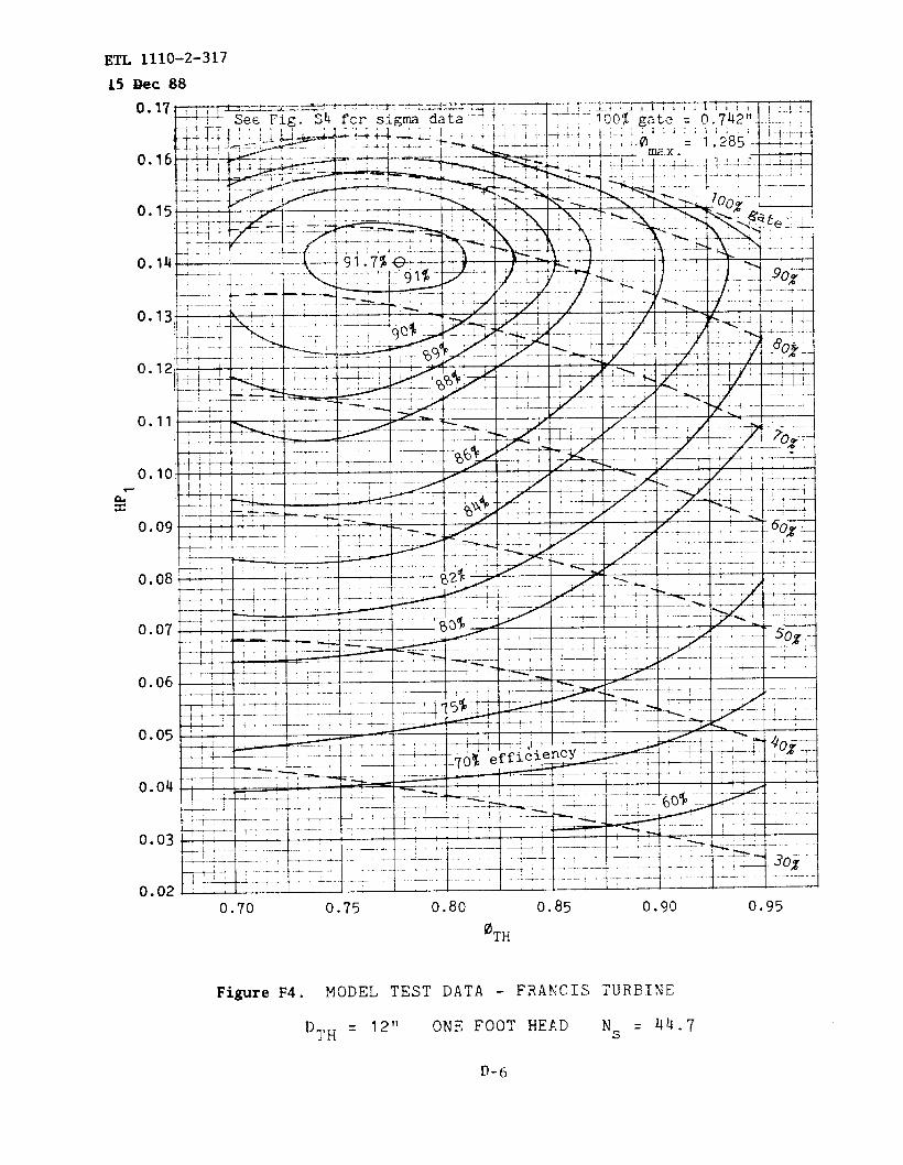
Em 1110-2-317
L!i??eC88
a’x
0.
0.
-.lo~;,!j” t I H 1 IdJ..L I-....+— .—---–4----—. 1 –J-- ..---- ..—.—+
o.o8
L.+—+L-–;-. .-.--i . .
‘“”’~-b~.. }.:=.+._._-.;–.....+.._._..{-..-.-y-....t._._.-jL—.:.1. ./ t-~- ----?- ;-7- l--–
1 I -~--+~~ ;..—.----.—--. -, !
—...–,—.—.7.
i ---- -~ -_ :+’-”:---+-’--’-~~=- ~ - ;___.... . .—-.—L.,.— t
-——..cl.uo~
+— -.-.+. 4 -—, ..’
+-.-–- -–— ---t
I
W:-5L----’---’3:.:*5~’Lq;! —..,___...I ...—:..0.04 ~ I
.—+
.— —-. . .. .-. ..—.
0.02II! I-- —.. –-—..+.-+ - - -“-~-”-:- + ““-’+------ 1- ..+.—.- ..---- .—-——.{
.L -._._.i----”--i
0.70 0.75 0.80 0,85 0.90 0.95
OTH
FigureF4. MODEL TEST DATA - FRANCIS TURBINE
‘1’H= 12”ONE FOOT HEJ.D N~ = 44.7
D-fj

ETL 1110-2-31715 I)ec88
0.04
r% 1 I 1 t /..— %
k.-. --—-
! ,+– ——...——-.,,, __ ,–._. ... _...-——,—-.:.11 -——- . —...
.— .—e-! . —. .—4. . &————.—-!- %— ——.. —-.——- .. .. . ..—-.——L—.— —-..—— ...+.- –
4—.-..—.—.—. ..——..— –_-. .—.. ——-—.— ~—. .- —..—.._——,.+_.————..7.—. .——T———.—.. . .—7*...–.-—..—.1–.—--.-———----- —=-..—,,,, —— ...= -I ,, —+–-.- .-,, —-q ,
40.7 0.8 0.9
0TH
FigureFS. MODEL TEST DATA - FRANCIS
‘TH = 12” ONE FooT HEAD
D-7
1.0 1.1
TURBINEN~ = 50.6

Em 1110-2-31715 Dec 88
0TH
0.30
0.05
0.30
0.28
0.26
0.24
0.22
% 0.20
0.18
0.16
0.14
0.12
0.10
FigureF6. MODEL TEST DATA - FRANCIS TURBINE
‘TH= 1211 ONE
.
FOOT HEAD N~
D-@
63.1

o.
0.
0.
0.
0.
“o.
o.
0.
0.
0.
0.
ETL 1110-2-31715 Dec.88
0.8
FigureF7.
0.9
MODEL TEST
‘TH= 72!!
1.0 1.1
0TH
DATA.- FRANCIS
ONE FOOT HEAD
D..~
1.2
TIJRBINE
N~ = 65
0.17
0.16
0.15
0.14
0.13
0.12
0.11
0.10
0.09
0.08
1.3

110-2=317
c 88
0,
t).
0.
0.
.im
x
o.
0.
0.
0.
0.
0.85 0.90 0.95
FigureF8. MODEL TEST
‘TH = 12”
1.000TH
1.05
DATA - FRANCIS
ONE FOOT HEAD
D-10
1.10
TURBINE
N~ = 80
1.15

. . .ETL 1110-2-317
15 Dec 88
b“wc(u
x*
61
20 30 40 50 60SPECIFICSPEED- N~
FigureF9. FRANCISTURBINES; PERFORMANCEHILL DATA -CONDITIONS.
‘TH = 12” ONE FOOTHEAD
70
BEST PHI
80
D-n

ETL 1110-2-31715 Dec 88
PAGE D-12 INTENTIONALLY LEFT BLANK
D-12
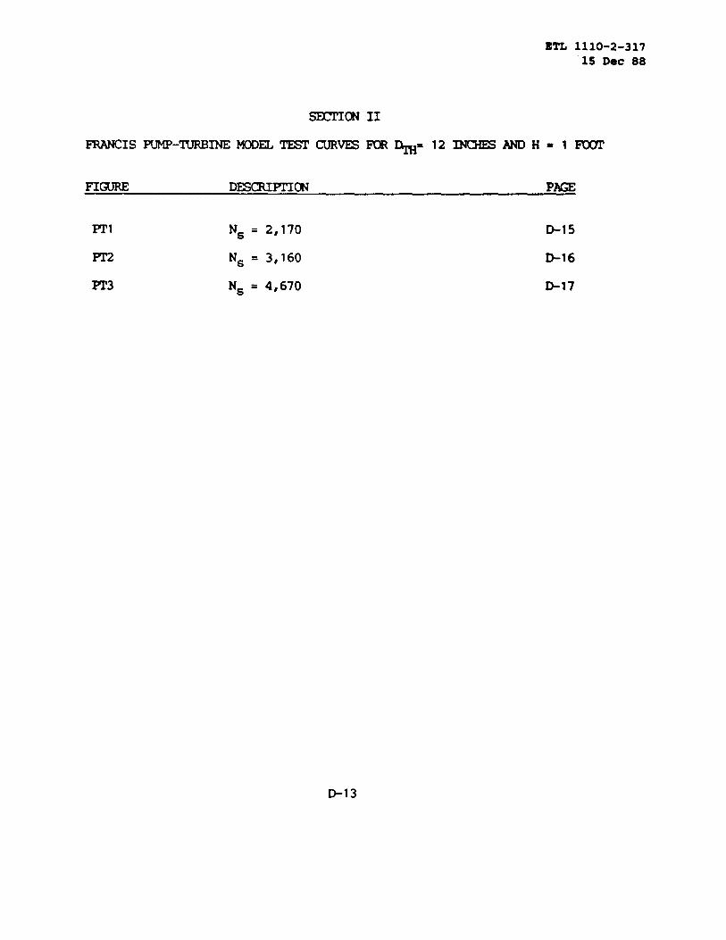
BTL 1110-2-31715 Dec 88
FIGURE D~PTION PAGE
Pr’1 N~ = 2,170 &l 5
N~ = 3,160 D-16
PT3 N~ = 4,670 -17
D-13

ETL 1110-2-31715 Dec 88
D-14

0.54 0.58 0.62
2.0
1.6
1.2
0.8
0.4
0.16
0.14
0.12
0.10
0.08
0.54 0.58
ETL 1110-2-31715 Dec 88
0.66 0.70 0.74
90
86
82
78
0.62 0.66
FigurePT1. MODELTEST
‘TH= 12”
OTH
DATA - FWC 1S
ONE FOOTHEAD
D-15
0.70 0.74
PUMP-TUR81NE
‘s= 2,170
0.4
0.3
6.2
0.1
0

*TH
C4’x
1,
n 7q 0.74 0.78 oa8~ 0.86 0.90+.-:: .+.-! ....+.~~3=w:T*. :+’~:=+”::;““‘-F;-;::..4:--2;;;>-”:”!IQ-1
40Q0
am
3000
2000
—T
. . . . . ..- . . . . -4.$
-:----\76,, ..,.)...—..
—anr ,,L&+.+——,
o.
0.
0.
-{~ IUO%gate-:.—, —
. .- .-— —.:- .—
i AIAQA . !.,! ——. L- ._ -.. :
0.70 0.74 0.78 0.82 0.86 0.900ahm.
Figure PT2. MODELTEST DATA - FWCIS
“n-l= 121’ONE FOOTHEAD
D-16
PW-TURJ31NE
‘s = 3,160
0.28
0.26
0.24
0.22
0.20
0.18

ETL 1110-2-317
.&5_:Q.e~.88
OTH
0.9 1.0 1.1
0TH
1.2 1.3
FigurePT3. MODELTEST DATA
‘TH= 12” ONE
D-17
- FRANCIS
FOOTHEAD
1,4
PUMP-TURBINE
‘s= 4,670
2.4
2.2
2.0
1.8
1.6
1.4
1.2
1.0
0.8
0.6
u
0.35
0.30
0.25

ETL 1110-2-31715 Dec 88
PAGE D-18 INTENTIWY LEF1’BLANK
B18

ETL 111O-2-31715 Dec 88
FIGURE D~FTION PAGE
FBI FWR BLAD= m AT 24° BLADEANGLE D-21
FB2 FIVE BLADESFl~ AT 31° BLADEANGLE D-22
FB3 SIX -= FIXEDAT 27° WE ~ D-23
X1 FWR ELADEKAPLANTURB~ D-24
K2 FIVE BLADEKAPLANTURBINE D-25
n SIX BLADEWLAN TURBINE D-26
D-19
—--——_

ETL I11O-2A31715.bec 88 ‘-
D-20

-u;
o.
?0.
o.
0.
0.
0.
0.
0.1.4 1.6 1.8 2.0
*TH
Fi&re FBI. MODELTEST DATA - FIXEDBLADE
FOUR BLADES 24° BLADEANGLE
‘m = 12” ONE FOOTHEAD
D-21
ETL ‘1I1O-2-317.15Dec 88
PROPELLERTURBINE
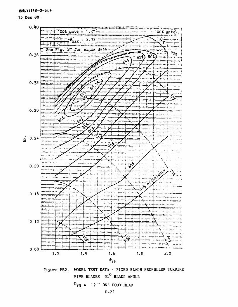
0.
0.
0.
0.
40
36
32
28
24
0.20
0.16
0.12
0.081.2 1.4 1.6 1.8 2.0
OTH
FigureFB2. MODELTEST DATA - FIXEDBLADEPROPELLERTURBINE
FIVE BLADES 31° BLADEANGLE
‘m = 12 “ ONE FOOTHEAD
D-22

ETL I11o-2-3I7.
LK Dec.$8
@.50bI 0.45
H
g 0.30
0.32
0.30
0.28
.0.26
0.24
0.22F&x
0.20
0.18
0.16
0.14
0.12
0.10
1.2 1.3 1.4
FigureFB3. MODELTEST
SIX BLADES
‘7’H= 12”
1.5
OTH
DATA - FIXEDBLADE
27° BLADE~GLE
ONE FOOTHEAD
D-23
1.6 1.7
86
84
82
PROPELLERTURBINE

m 1110-2-31715 Dec 88
I
2.C
I
1.5
1.0
0.5
0.4
0.3
0.2
0.1
0
! I 1 1, I I &1 ! 1 T 1 I 1 I I I 1 1 ! 1 I z 1 I w! I uI 1 I UI
I,
Figure K1. MODELTEST tiATA- FOUR BLADEhPM’ TURBINE
‘m= 121’ ONE FOOTHEAD
D-24

ET L111O-2-31715 Qec 88
o.
0.
0.
0.
0.
0.
0.
0.
0.
0.
44
40
36
32
28
24
20
16
12
081.2 1.4 1.6
FigureK2. MODELTEST
‘m = 12”
1.8 2.0
0TH
DATA - FIVE BLADE
ONE FOOTHEAD
2.2 2.4
KAPLANTURBINE
D-25

m 1110”2-31715 Rec 88
0.44
0.40
0.36
0.32
0.28
0.20
o.I6
0.12
0.o8
0.041.2 1.3 1*4 1.5 1.6 1.7 1.$
OTH
Figure K3. MODEL TEST DATA - SIX BLADE KAPLAN TURBINE
‘n-I= 12” ONE FOOTHEAD
D-26

ETL 1110-2-31715 Dec 88
FIGURE D~~ON (FRANCIS) PAGE
S1 REFERS~FIGUREFl W29
S2 ~mFIGuREF2 D-29
S3 REFERS~FIGUREF3 D-30
S4 ~’N)FIGUREF4 D-30
S5 ~mFxGuREF5 B31
FIGURE D~ON (- HE FROPELLER) PAGE
S6 REFERsm FIGuREFBl D-32
S7 ~mFIGuREFB2 D-32
FIGURE D~PTION (KAPLAN) PAGE
S6 REFERsm FIGuREK2 D-33
S7 ~mFIGuREK3 W34
D-27

ETL 1110-2-31715 Dec 88
D-28

ETL 1110-2-31715 Dec 88
, , I !i; :#:-—--—–—4- -–-1t–
! 1 I II 1 , Ii; I. .--+— --.-–. ---–l – -
1—. --— :. . ...— * ,
. ..U. L!,
–———. — . . . . . _—: _:..
Lo
—J+— ---- + -—-— -
, . .—. ..— _
, 0.05.L— 1.. –. ._J_:. , ..... -. ——-- ---–— —.——
s ,,-t4 - .+4 L-- .- .:.- .-- ;.. -J-J- -0 ,, ,,, ,,
4
d4u
H ~—.. —. . . . . . .. . .
Iz.<. . ...= —— -!, I
,, +.-. . .. ... .- * —+. ..+, ... ..——.
0.02-’-----.-..._...+. ..—..-.——.—._—..
I
4g
Hm
0.52
0.
0.
,0.
0.
0.
0.
0.
0.54 0.560TH
0.58 0.60 0.62
FigureS1
0.60 0.64 0.68 0.72 0.76 0.80
OTHFigureS2
FRANCIS TURBINES
CRITICAL RUNNER SIGMAS
D-29 FiguresS1 and S2

m 1110-2-317
Is-c 88
0.16
0.14
,00.12
0.10
0.08
0.06
0.04
0.02
0
0.16
bv 0.14
+i:i:-c+_–+.**Ti&-::=i--:.-7T7T ::-:=-- ---1--- ~-- ‘- “-:”, t , %?
.— — -m_–. .:—J —--- .l:-— -- 1— 1 . . . ..~,-d -——- --- -:: --:-””.::-..:- .-.-f---‘-:.=’ -—--. —-. . . ..—. —.— —_.i: ia l ..-. .:. .–—. –-.– : . .- . . . . ...1 . ..—. .rua.ti.ah ———..~
~. —..
t- —+—-=—4.....——L..UL -—-—. —--..-–._L_ ___
.—4=:--+ .--------+--e .—
.&.——-–_.<. ... L----- ...4——...—+..——.;. .._..% —...–.
—.&.-
———
..: ..
-—..—
0.68 0.72 0.76
*TH
0.80 0.84 0.88
FigureS3
———.—-.. — -.. .— .. .. . . . 1. _ ~~——— -- -- _.___ .—_— —_ _.—
..—..
-..—.——+.:.
A__. ——”—--..._. — ..—.
0.06
0.70 0.74 0.78 0.82
OTH
0.86 0.90
FigureS4FRANCIS TURBINES
CRITICAL RUNNER SIGMASb30 FiguresS3 and S4

ETL 1110-2-317
15 Dec 88
0.18‘“,—--~t1 17+Y
L+ ---- — . —.. .—.–..—r — . —.—+. -..
. .;- -“”
..+— .—__. — -. ,– 44. —L . . . . . . _-_..
. . . . . . . . . . . . . . . . LA.. .LL—. .— - ~ .–. -—- .- —- . —-—L––. . — . ..-—
-. —.. ..- . . . . . .—. ..— .–-l.— . . . . . . . . . . , .. —- —. .: –.__
—-—. .
L, ..- —.. . . . .
.-. 2+. +.. .– .-L
2un
a
1,
d
3
.+ —.-. .— ——. .—
g o.lo -HG
.---- . .
u ,, ~..–! ‘-- ..+. —.. .
. -— .— -——.. . . .
- -A. . . . . . -.+. ~—+.
0.06—.7:-–--+–---–-
L -.—. . .-...........-.—.——.-.—+
1-+.4-––..–+—–——-– +~–.--+ -—.--——...—.—.—.._.—._____
-.-+.- ——...—-.—. -—-
0.04—T-.-1-- .-—.-. ....-——— .—r-.....–.l.A .-.4..—.—+-——-——L.–-..—.–L—.–--, .-...-1.-.-–.-..—...L.__.&l.--,-----.;-;.i.-.–~.<1.L.+---.–.
.—4— ——-—..-—.......—.
-+—.-.—...__+_-y-+4+
~— -...+.-....—-. ..——.+-—.— -—-.-—- + .+J.._— -._.— ----!,
0.70 0.75 0.80 0.85 0.90 0.95
OTH
FRANCIS TURBINE
CRITICAL RUNNER SIGMAS
D-31 FigureS5

ETL 1110-2-31715 Dec 88
t .3
1.2
1.1 ,— - 4 . ——-—.y
7-~—. .-. . . .. —.._. —-.. —
b“I
1.0
0.9
0.8
0.7
0.6
0.5
1.0
0.9
-–% --.+---- -“-~j---:+~+~ -f’=---’4- --~--’~“ ---’-* ...
.+
____
. .
1.6 1.7 1.8 1.9 2.0 2.1
FigureS6OTH
b“0.8
0.7
0.6
0.5
0.4
l. . .._.,. --–— ;--- :---..1 .- . . ..– . . . . . ~“”no$ ?Y-—...
I
-—
~ —.. .. .. .i—.,-.-~.. i:::+;
A.——-.—--- ...._—._1-—.—,.--—-—.—.—-.—L—. . . .
1.4 1.5 1.6 1.7 1.8 1.9
OTH.. -. FigureFIXED BLADE PROPELLER TURBINES
CRITICAL RUNNER SIGMAS
D-32 FiguresS6 and
2.C
S7
S7
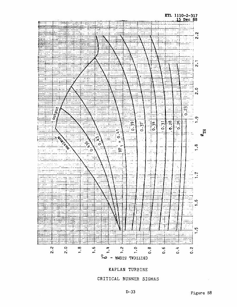
ETL 1110-2-317fi Dec 88
-4;.-’ - i ___ _:
---+—
KAPLAN TURBINE
CRITICAL RUNNER SIGMAS
D-33 FigureS8

ETL 1110-2-317..15Dec &8
o)
1.4
1.3
1.2
1.1
1.0
0.9
0.8
0.7
0.6
0.5
0.4
0.3
0.2
0.1
0
1.2 1.3 1.4 1.5 1.6 1.7 1.80TH
KAPLAN TURBINE
CRITICAL RUNNER SIGMAS
&34 FigureS9

ETL 1110-2-31715 Dec 88
APP~IX E
SAMPLE~TIONS
-ON I
FRANCISTYPE lURBINESAND PUMP-TURBINES
1 DESIGN~~ E-3
2 S~ION OF PUMP-’KJRBINES E-3
3 ~TING CYCLE E-7
4 CONVENTIONALFRANCIS~INE E-9
5 PR~E DIMENSIONS E-13
E-1

ETL 1110-2-31715 Dec 08
E-2

ETL 1110-2-31715 Dec 88
-a. Powerplant~pacity - 150,000 KW
b. Installation:2 -turbines and one conventionalturbine.
. ~ing requir~ts: 3,600cfs each at a dynamichead of 153feet: The headsvary between137.5and 160 feet. The mininumtailwaterlevelfor ~ing is Elev. 540 ft. m.s.l.
d. Generatingrequir~ts: The 3 units mst have an aggregatedependablecapacityof 150,000W. The 3 unitsnust also be capableofproducing170,500W at a net head of 137.4 feet. The net heads varybetween 132.5 and 151.9 feet. The average (ratd) net head is 144.8feet.
2. sELEcrIoNOF w-m-.
ReferenceFigure 2, ~ C to note that the r~edspec~~icspeed,N= for the 153 foot rated wing head has a value of-t 4,000.
b. Referringto the tiel curves in Appendti D, selectthe designshownon Figure~3 as the best choicefor this specificx.
At maxm efficiency,note the following: El = 87.4 percent,Q1 ==;.57Cfs ti ~ = 1.15.
d. Calculate~:
3,600 =
()
1.57 b 2 (153)1/2T
~ = 163 inches
e. Calculatespeed,N:
(153) ’/2 = 160 ~163
N. 1838 (1.15)
f. The calculationofsynchronousspeed generally
the runner throat di-ter and associatdrequires an it~ative solution. Wer
E-3

ETL 1110-2-31715 Dec 88
iterations are required-until the selected value for ~~ and as-iatedvalue of Q1 produce a value for DT which substituted in the speed
iequation, step e, yields a sync ronous speed. The followingapproximationis us~tocalculate the next trialvalueof ~:
% = 1.15 ~= 1.176
The neces~ iterationsfor this case are as follows:
Step %% % N
1 1.150 1.57 163.4 160.0
2 1.176 1.65 159.4 167.8
3 1.160 1.59 162.4 162.4
4 1.165 1.61 161.3 164.2
5 1.162 1.60 161.8 163.2
The accuracyin reading the tiel test data does not allowa closerdetermination of D
Eor N from step 5. Therefore, the solution
ificates ~ = 162 ches for N = 163.6rpfn.
9“ At &is point the user should tie a cursory examinationof thewing efficienciesfor other heads with a view to, perhaps,changingthe speedto alterthe headafficiencycharacteristic.In this _le,the followingrelationshipsare noted:
%=163.6 (162) = 14.42
1838 (H)’/2 ~
H El
160.0 1.140 87.4
153.0 1.166 87.3
137.5 1.230 86.3
This relationshipis satisfatioryand the klance of the _le is~letedontheksisof ~ = 162 i..nchesandN= 163.6~.
E-4

ETL 1110-2-31715 Dec 88
h. Calculateefficienq step-up.
()D 0.2
E2 = 100- (loo- EI) mq
Wh=e, w. El = 88.5-cent (generating);Dm = 12 tithes;Dp= 162 inches.
E2
()
= 100 - (100- 88.5) 12 0“2 = 93.2percent”m
step-up= (2/3)(93.2,-88.5)= 3.1 percent
i. The expected-ing distige is calculatedto includethe effectof the higherprototypeexpectd efficiencyas follows:
()162 2Q2C= Q1 ~
(“]1/2‘2Y
j. The requird -ing
Q2C \‘HP=
550 E2
‘1
horsepoweris calculatedas follows:
k. The rqired settingof tie runner is controlled@ the ~head-rein- tailwatercotiition. For maxinum head, OTH = 1.14 andfrunFigureFT3, ~ = 0.295.
Hb - ~ - Hs - safetyd= =
H
Referto Figure6, AppendtiC: For tailwaterElev. 540, Hk = 33.3 feetand a watert~ature of 70° F., ~= 0.8 feet. “
safetymgin =
Referto Table 3, mix
0.2 Di + 0.4 Hi/2
C, notingthat D, = 1.154
E-5

ETL 1110-2-31715 Dec 88
therefore,D1 = 1.154~ = 15.6feet12
subs: safetymargin= 0.2 (15.6)+ 0.4 (160)1/2= 8.2 feet
The requird s*gence is calculatd as follows:
33.3 - 0.8 -Hs-8.20.295=
160
H~ = -22.9feet
The distance, a, between the bottom of the runner and thedistributorcenterlineis calculatd using the ratio,d, from Table 3,~ C, as follows:
d = 0.385
a= 0.385(162/12)= 5.2 feet
The elevation of the distributor centerline is calculated asfollows:
Elev. = tailwaterElev.+ H~ + a
Elev. = 540 + (-22.9)+ 5.2 = 522.3ft. m.s.l.
1. The -d pqing performanceis as follows:
Head 137.5 145.0 153.0 160.0
% 1.230 1.198 1.166 1.140
Q1 1.82 1.72 1.62 1.53
El 86.3 86.8 87.3 87.4
Q2C 4,029 3,909 3,777 3,652
E2 89.4 89.9 90.4 90.5
HP 70,200 71,420 72,410 73,140
E-6

ETL 1110-2-31715 ‘Dee88
3. ~mcYm.
a. The prototype-d perfo~ce is calculatedas follows:
%=162 (163.6) 14.42
1838 (H)l/2==2
HP~ = HPl ()162 2~ (H)3/2 = 182.25 (HPl) (H)3/2
550 HP2 HP2
Q2 = 62.3 (H) ~ = 8.828—‘%
~ = El + 3.1 percent
PercentHead ?rH gate HP, El HP2 Q2 %
132.5 1.253 100
90
80
70
60
137.4 1.230 100
90
80
70
60
145 1.198 100
90
0.204
0.198
0.185
0.164
0.140
0.203
0.198
0.187
0.166
0.143
0.202
0.197
83.3
84.6
83.9
80.9
76.0
83.5
85.0
84.7
82.1
78.0
83.6
85.2
E-7
56,710
55,040
51,420
45,590
38,920
59,590
58,120
54,890
48,730
41,970
64,280
62,690
4,375
4,180
3,940
3,615
3,280
4,420
4,240
4,015
3,675
3,325
4,515
4,320
86.4
87.7
87.0
84.0
79.1
86.6
88.1
87.8
85.2
81.1
86.7
88.3

ETL 1110-2-31715 Dec 88
80 0.188 85.9 59,820 4,090
70 0.169 83.8 53,780 3,765
60 0.147 80.0 46,780 3,425
50 0.119 74.0 37,870 2,990
151.9 1.170 100 0.200 83.5 68,240 4,580
90 0.197 85.2 67,220 4,425
80 0.189 86.5 64,490 4,180
70 0.171 85.0 58,340 3,850
60 0.150 81.8 51,180 3,505
50 0.123 76.8 41,970 3,055
b. The ~ runawayspeedis calculatedas follows:
ReferFigurePI’3to note that ~ = 2.09
89.0
86.9
83.1
77.1
86.6
88.3
89.6
88.1
84.9
79.9
~= 1838 (2.09) (151.9 )1/2 =292~162
. The guarant~ capacitiesat the 132.5 foot and 137.4 foot netheadcconditionsare calculatedat 98 percent of the 100 per-t gate=pacities indicatedin *ve ~lation. The guarant~ capacitiesforthe conventionalunit at thesetwo headsare as follows:
Kw Outpt = 0.98 (0.746)Eg HP2
m output= 0.98 (0.746)(0.97)HP2 = 0.709HP2
Head - feet 132.5 137.4
Plantoutput- Kw 150,000 170,500
-turbines - KW 80,400 84,500
E-8

ETL 1110-2-31715 Dec 88
Conventional- KW 69,600 86,000
Conventional- HP 96,180 118,850
---~ 98,140 121,280
4. ~IONAL FRANCISTURBINE.
a. The relationshipfor Ns vs. Head shown on Figure 1, AppendixCinsures designs with moderate speeds and relatively shallowsubmergence. In a mixed installation with pump-turbines andmnventional turbines,the inh=ent deepers~gences r~ird of thefo~ generallydictates a variationof this conservativeapproach.This is necessaryto providea mre balancedequi~t layout- avoidwggerat~ levels for the generator-mstorsand generators. For thisr=son the “K” valueus~ h Figure 1 is increasedto, say, a value of800. The mrrespoding Ns for H = 144.8feet is 66.5.
b. Referringto the @el curves in AppendtiD, it my be notedthat the designsshownon FiguresF6 ti F7 are withinthe rangeof thisspecificspeed. A corr@arisonof thesedesignsindicatesthat the fo~has higherunitpowerwith att-t highermitical si~s, wher~s thelatterhas higher overallefficacies with lower criticalsi~s Mreducedunit PWW. The formerdesign,FigureF6, is selectd for thefollowing reasons. The higher unit power will result in a smallerrunner~oat diameterwith mnsequent roller physicaldimensionsofthe turbineto mre nearlyapproachthe physicaltisions of the ~turbines. The higher critical sigmas require deeper sutiergences,however,this is not inappropriatein view of the deep ~gen~ ofthe Purrp-turbines.
c. The method for sizing this unit differs from the conventionalapproachfor Rancis turbines. In this instance,the atput requiredatthe 137.4 feet critical net head dictates the size. This output isassociatedwith the fullgate capacityat a valueof ~ slightlyhigherthan the best ~ to be associatd with the averagehead of 144.8feet.For the latterconditiona ftist value of o~ = 0.86 is chosen. Thecorrespotiingvalue for the 137.4fti head cotiitionis calculatd asfollows:
(-)~= 0.86 144.81/2=0.883137.4
FrmFigure F6 for ~is associated with the
= 0.883, the 100 percent gate HP = 0.29. Thisrequired expected output of 121,280 HP to
E-9

ETL 1110-2-31715 Dec 88
~lculate ~ as follow5:
121,280= 0.29 ~~2 (137.4)3/2”\l-2j
d. Calculate
N=
= 193.4 inches
the e, as follows:
1838 (0.833) (137.4)’/2 = 98.4193.4
R@ to nearestsynchronous_ = 100 P
This speed and the ~H calculated a~ve are first values of aniterativesolutionsimilarto that describedin 2.f. of this -le.The necessaryiterativestepsare as follows:
1 0.883 0.29 193.4 98.4
2 0.897 0.29 193.4 100
Round~ to 193.5 inches
e. fie expectedprototypemtput is calculatd as follows:
()= HPl 193.5W2 —2 (H)3/2 = 260.02 (Wl) (H)3/2
12
f. The efficiency step-up is calculated, using the procedureestablishedin 2.h. of this _le, as follows:
HE2 = 100- (loo - 90) 1; So”z.
E2 = 94.3 percent
step-up= (2/3) (94.3 - 90) = 2.9 percent
9“ The -ed dischargeis calculatd as follows:
E-10

ETL 1110-2-31715 Dec 88
550 HP~ m~= 8.828
~Q2=62.3 (H)E2
h. The guarant~ capacityrequird at the 137.4 feet critiml head is118,850HP. The generatoroutputis 86,000KW. The generator-plateratingis 86,000KW at 0.95p.f. or 90,526WA. The turbineis designedto mechanicallywiths~ operationat the generator~plate ratingat 1.0 p.f. or 125,100W. me turbinesettingis predi=ted on theavailabilityof 118,850HP at the criticaland higher h-ds. Althoughthe criticalhead conditionswill generallydictatethe sett~, it isr~ed that otherconditionsbe checkedto assurethat the criti=lsigmachara~eristicsof proposeddesignor unusualtailwaterconditionsdo not alt= this no-l cticumstance.
i. The proceduredescribedin 2.k. of this _le is used to establishthe turbine setting. The dimensionless ratios for calculating thedimensionsDi and a are obtainedfrom Table 1, ~ C. me resultsof pertinentcalculationsare tabulatedas follows:
Net head, feet
T.W. elev.,ft.m.s.l.
HP
h
HP,
d=
Hb, f=t
q, feet
Di, feet
Safetywgin, feet
H~, feet
a, feet
137.4
550.8
118,850
0.898
0.284
0.245
33.3
0.8
14.2
7*5
-8.7
6.9
144.8
548.5
118,850
0.875
0.262
0.1830
33.3
0.8
14.2
7.7
-1.7
6.9
151.9
541.6
118,850
0.854
0.244
0.160
33.3
0.8
14.2
7.8
+0.4
6.9
E-11

ETL 1110-2-31715 Dec 88
Dist.elev, ft. m.s.l. 549.0 553.7 548.9
j-
k. The
It is to be noted that the conditions at the critical and~ headsdictatetit the ~ setting.
The ~ runaway_ is alculated as follows:
RmFigureF6, ~-= 1.671
k=1838 (1.671) (151.9)’/2
193.5= 195.6 ~
Head HP, El HP2 Q2 %
132.5 0.915 0.123
0.148
0.185
0.217
0.241
0.258
0.273
0.285
0.290
137.4 0.898 0.122
0.148
0.211
75
80
84
87
89
89
87
84
82.5
75
80
87
48,780
58,690
73,370
86,060
95,570
102,320
108,260
113,020
115,010
51,090
61,980
88,360
77.9 4,170
82.9 4,715
86.9 5,625
89.9 6,375
91.9 6,930
91.9 7,415
89.9 8,025
86.9 8,665
85.4 8,970
77.9 4,215
82.9 4,805
89.9 6,315
E-12
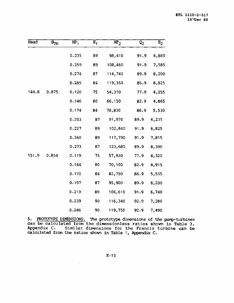
ETL 1110-2-31715’~ec 88
0.235
0.259
0.274
0.285
144.8 0.875 0.120
0.146
0.174
0.203
0.227
0.260
0.273
151.9 0.854 0.119
0.144
0.170
0.197
0.219
0.239
0.246
89
89
87
84
75
80
84
87
89
89
87
75
80
84
87
89
90
90
98,410
108,460
114,740
119,350
54,370
66,150
78,830
91,970
102,840
117,790
123,680
57,930
70,100
82,750
95,900
106,610
116,340
119,750
91.9 6,880
91.9 7,585
89.9 8,200
86.9 8,825
77.9 4,255
82.9 4,865
86.9 5,530
89.9 6,235
91.9 6,825
91.9 7,815
89.9 8,390
77.9 4,320
82.9 4,915
86.9 5,535
89.9 6,200
91.9 6,740
92.9 7,280
92.9 7,490
5. PR~E D-IONS. The prototypedimensionsof the purrp-tu.rbinescan be calculated from the dimensionless ratios shown in Table 3.Appendix C. Similar diwnsions for the Francis turbine can ~calculatedfrm the ratiosshownin Table 1, ~ C.
E-13

Em 1110-2-31715 Dec 88
E-14

BTL 1110-2-31715 Dec 88
~ION PAGE
1 D=I@ ~ E-17
2 TURBINE ~oN E-17
E-1 5

ETL 1110-2-31715 Dec 88
PAGE E-16 ~IONALLY LEFT RLANK
E-16

1.
ETL 111O-2-31715 Dec 88
DESIGNw UI~ .
a. Powerplantcapacity: 65,000 W with 2 units.
b. Generatorrequirmts:
(1) Nmplate rating: 36,111KVA, 0.9pf., 32,500KW, 13.8KV- 60 Hz.
(2) Must hdesigned for continuousoperationat ratedKVA,voltage,p.f. - frequency.
c. Turbiner~ir~ts:
(1)
(2)
(3)1.0p.f.).
Net heads: 78 fmt rated,60 foottitiand 100 fmt~.
Require30,000HPguaranteedoutputat 60 footnet head.
Turbineoutputis limitedto 49,900HP (ratd KVA at
2. ‘IURBINE~ION.
. To utilizethe capabilityof a generatormatedwith a ftiedblad~propellerturbine,the turbineat or near bst efficiencyat ratedhead &ould have an atput ofthe generatorrating:
HP= 0.95 (32,500)0.746 (0.97)
95 pcent of the horsepowerequivalentof
= 42,600
b. ReferenceFigure3, AppendtiC to note that the ratedheadcofition and the wide head range for this unit dictatesa 6 bladerunner. The r~d ~ific _ at the 78 footratedhead iscalculatd as follows:
N5 = 1,000 = 113.2(78) ’/2
E-17

ETL 1110-2-~1715 DOC 88
c. The - is calculatedas follows:
N=113.2 (78)5/4 = ,27 ,
(42,600)’J2 “
R- to nearestsynchronousspeed= 128.6 rpm
Correcting = 114.5
d. For preliminarystudiesrequiringrunnerthroatdiarrket~,the followingused to calculatethe dimter:
only an apprbte speedand~irical fomla for ~ may k
~= 0.089 (114.5)0”58= 1.391
%=1838 (1.391) (78) ’/2 = ,75 6 tides
.128.6
e. The appropriatetiel test curvesfor theseconditionsare shownonFigureFB3. A curveof hst efficiencyis construed fromthefollowingdata taken fra the efficiencycontours:
hHP,
The locationiteration. This
ofis
1.230 1.290 1.350 1.420 1.515
0.244 0.256 0.264 0.272 0.290
the designpointalongthis curveis det-ned @a~lished by stiitut~ as-iated valuesof
HPl and ~ in the followingfornulafor specificx:
N~ = 153.17(~) (HP1)’/2= 114.5
The apprhte value~ = 1.391fran (d)tive is u- in tieftiststep of the iterativeprocessas follows:
% 1.391 1.440 1.430
HPl 0.2685 0.2745 0.2730
N~ 110.4 115”.6 114.5
E-18

ETL 1110-2-31715 Dec 88
The designpoint is locatd at ~ = 1.430 and HPl = 0.2730. Therunnerthroatdiameterfor this preliminq selectionis =lculated asfollows:
f. It mycalculatd
42,600=
()
0.273 &2 (78)3/212
~ = 180.6inches
be notd from inspectionof FiqureFB3 that the desiqnminttive is locatd ~o the right&f &t The tiel effic~en~ at
this point is El = 87.9percent,which is lessthan the 88.4per-tpeak efficiency. The peak efficiencyat the ratd conditionscan be*rovd by selectingthe n* lowersynchronousspeed,120 rpm, andrepeatinqthe iterativesolutionfor the new desiqnwint. Thecalculationsand
N~ =
~lation of the it=ative step=tie as follows:
(42,000)1/2
(120) = 106.8(78)5/4
()Use firsttrial~ = 1.43 120 = 1.334128.6
% 1.334 1.362 1.355
ml 0.2620 0.2650 0.2645
N~ 104.6 107.4 106.7
Calculatethe runnerthroatdiameter:
42,600=
()0.2645%2 (78)3/2
T
~ = 183.5 inches
~“ The secondsel~ion mt&es the peak efficiencyof this desiqnto& rated conditions. This is aql~shd~ unit. At this point in the selection
E-19
by seltiing a l~,-lowerprocess,the user RUSt

ETL 1110-2-31715 Dec 88
evaluatethe increasd &pital costsofbenefitsof the higherefficiency.Theon tie powerhousestructure,excavationin the turbinesetting,generatorcost,is arbitrarilyusd in the r~inder of
the larger unit against thecosts shouldincludethe effectstakinginto accountany change. . . etc. The latterselectionthis exarfple.
h. The tiel test curvesrrustbe *ed to assureguarant- outputat 60 footminirrumnet head can bepr~sd design. The necessary calculations in thisas follows:
~ = 120 (183.5) = 11.98 = , ~47
1838 (H) ’/2 (H)l/2 -
30,000 =
()
183.5 2 (60)3/2ml —12
HPl = 0.2760
Referringto FigureFB3 at ~ = 1.547,note(loopercent)outputis HP, = 0.3070.
that the 30,000 Wdeveloped with thedeterminationare
that the fullgate
percent
tie designoutputis at least
0.307margin . —002~6 (100) = 111.2 percent
=ts the requir~t that the expectedfullgate2 percentgreaterthan the guarantq output.
i. The prototypeexpectedperfomce is calculatedas follows:
()W2 —2
= HPl 183.5 (H2)3/2 = 233.84 (i-iPI)(H2)3/212
,2 0.2
()~ = 100- (100- 88.4)— = 93.3percent
183.5
step-up= (2/3)(93.3- 88.4)= 3.3 percent
Ec = El + 3.3 pcent
E-20

ETL 1110-2-31715 Dec 88
550 W2 HP2Q2 = 62.3 ECH2 = 8.828—
E= H2
H2 ?cH HPl El HP~ E= Q2
60 1.547 0.184
0.208
0.234
0.247
0.264
0.272
0.282
0.304
0.307
78 1.356 0.159
0.181
0.204
0.214
0.226
0.231
0.238
0.244
0.254
70
75
80
82
84
85
86
86
85
70
75
80
82
84
85
86
87
88
20,000
22,610
25,430
26,840
28,690
29,560
30,650
33,040
33,360
25,610
29,160
32,860
34,470
36,410
37,210
38,340
39,310
40,920
73.3 4,015
78.3 4,015
83.3 4,490
85.3 4,630
87.3 4,835
88.3 4,925
89.3 5,050
89.3 5,445
88.3 5,560
73.3 3,955
78.3 4,215
83.3 4,465
85.3 4,575
87.3 4,720
88.3 4,770
89.3 4,860
90.3 4,925
91.3 5,070
E-21

ETL 1110-2-31715 Dec 88
H2 HF~ El HF~ Ec Q2
0.264
0.271
0.278
0.282
0.285
0.287
100 1.198 0.135
0.165
0.191
0.202
0.213
0.219
88.4
88
87
86
85
84.4
70
75
80
82
84
85
42,530
43,650
44,780
45,430
45,910
46,230
31,570
38,580
44,660
47,240
49,810
51,210
]0 The setting of the turbinede-sand the relatedhead-tailwatercofitions.pr~icated on the tailwaterlevelwith one
91.7
91.3
90.3
89.3
88.3
87.7
73.3
78.3
83.3
85.3
87.3
88.3
5,250
5,410
5,615
5,755
5,885
5,965
3,800
4,350
4,735
4,890
5.035
5,120
upon the outputrqirementsThe settingis generallyunit ~atim. For this
tile it is ass~ that it is desiredto opera~ethe &it atgeneratorratingand 0.9 p.f. underthe ratedand higherheads. Themrrespondingturbineoutputis 44,500W. Mer noml cirmtancesthe rated conditiondictatesthe setting. However,it is gocd practimto checkthe utherhead renditionsto assurethat unusualsigmacharacteristics or head-tailwaterrelationshipsdo not alterthis nomlcircumstance. The outputrequtiementsat the lowerheadsare assumedtovary directlywith the head betweenthe 44,500HF at 78 footd the30,000HP guaranteedoutputat 60 foothead. The relation~ip ktweentailwaterlevelh dischargeis linearktween the followingsetsoftitions:
E-22

ETL 1110-2-31715 Dec 88
TailWaterElev.-ft.m.s.l. 543.0 545.7
Discharge- cfs 5,000 11,000k. The followingstepsare requiredto establishthe turbinesettingson the basisof the conditionsset forth*ve:
I
mom
E= =
Q2 .
‘ T.W.
233.84H3/2
Figure FB3, pick off &c W El
El + 3.3 percent
8.828 (HP2)
E= (H2)
Q2Elev. = _ + 540.752222
@c =Hb-~-H~-Safety
H2
Run Figure6, ~ C: Hb = 33.3 feet,~ = 0.8 f~t (70°F.)
safety= 0.2 ~+ 0.7 (H2)’/2
Distr.centerlineelev. = T.W. elev.+ Hs + a
a= (d)%
Referto Table 4 ti Figure5, ~C to noted = 0.365
a= 0.365 (183.5/12)= 5;6 feet
E-23
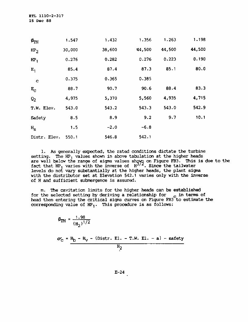
ETL 1110-2-31715 Dec 88
%
HP~
HP,
El
c
E=
Q2
T.W. Elev.
Safety
H~
1.547
30,000
0.276
85.4
0.375
88.7
4,975
543.0
8.5
1.5
1.432
38,600
0.282
87.4
0.365
90.7
5,370
543.2
8.9
-2.0
1.356
44,500
0.276
87.3
0.385
90.6
5,560
543.3
9.2
-6.8
1.263
44,500
0.223
85.1
88.4
4,935
543.0
9.7
1.198
44,500
0.190
80.0
83.3
4,715
542.9
10.1
Distr.Elev. 550.1 546.8 542.1
1. AS generally-d, the ratd co~tions dictatethe turbinesetting. The HPl valuesshownin tive tilatim at the higherheads
H~~ ‘~~~v~e~dilnterare well -low the rangeof si~ valuessh This is due to thefactthat HPl varieswith the inverseof .levelsdo not vary substantiallyat the higherheads,the plant sigmawith the distrtitor set at Elevation542.1variesonly with the Inverseof H @ sufficients~gence is assured.
m. The cavitationlimitsfor the higherheadscan te establishedfor the selectedsetting@ derivinga relationshipfor h termsofhead then enteringthe criticalsi~ curveson FigureFB3ctoesthte thecorre~nding valueof HPl. This procedureis as follows:
h= ‘“98
-c =
(H2)’/2
Hb - ~ - (Distr.El. - T.W. El. - a) - safety
H2
E-24

By substitutingElev. 543, this
c=
known valuesand allowinga mnstant tailwaterequation~s:
35.9 - 0.7 (H2)’/2
ETL 1110-2-31715 Dec 88
level at
H2
A s~ of the ~ outputlimitsis as follows:
H2 % c ml ~2
80 1.339 0.370 0.270 45,180
82 1.323 0.361 0.268 46,530
84 1.307 0.351 0.266 47,890
86 1.292 0.342 0.264 49,230
86.5 1.288 0.340 0.264 49,660
The limitingoutputof 49,500HF can & develcpedat 86.5 fxt and thehigherheadswithoutcavitation.
n. The prototype~ runaway~ is esthted as follows:
Refer
0. Asan
%
to FigureFB3 to nute that ~ = 2.765
~= 1838 (2.765)(100)1/2=277~183.5
=ercise, the user my el~ to analme the -its of thefirstselectionwith N = 128.6 fi @
2= lhO.6 inches. fiis will
f-liarize the user with the fornulas proceduresrequiredtodevelopthe necessarydata for a givendesign.
P- The prototypedimensionsof the principalparts and waterpassagesof the turbinecan be calculatedfranthe visionless ratiosshowninTable 4 -h C.
E-25

ETL 1110-2-31715 Dec 88
E-26

ETL 1110-2-31715 Dec 88
APP~IX E
=ION III
MSI’AELE BLADEPROPELLER~INE
S~ION PAGE
E-27

ETL 1110-2-31715 Dec 88
E-28

ETL 1110-2-31715 Dec 88
1. DESIGN m~ :
a. PowerPlantcapacity: 69,000 KW with 2 units
b. Generatorrequir~ts:
(1) N-plate rating: 36,320KVA, 0.95p.f., 34,500KW, 13.8KVand 60 hz.
(2)Must &designed for mntinuous operationat ratd ~Aatratd voltage,p.f. and frequency.
c. Turbinerequir~ts:
(1) Net heads: 70 footrated,53 fti mininunand 88 foot~.
(2) Requtie33,200HP guarant~ outputat 53 fmt net head.
(3) ~bine outputis limitd to 50,190HP (ratedKVA at 1.0p.f.)
(4)The settingrequiresa concrete~-spiral case.
2. TURBINE~ION.
a. The turbineoutputmlculated as follows:
requiref3to matchthe generatorratingis
HP= 34,5000.746 (0.97)
= 47,680
b. Referto Figure3, ~ C to note that the ratedhead renditionand the wide head range for this unit dictatesa 6 bladerunner. Ther~d specific~ at the 70 fmt ratedhead is calculatedasfOllows:
Ns = 1,100,- = 131.5
(70)l/~
c. The speedis calculated
N=131.5(70)5/4
(47,680)’/2
as follows:
= 121.9
E-29

ETL 1110-2-31715 Dec 88
Round to nearests@chron~s _ = 120P
tirr~ed N~ = 129.5
d. For preliminarystudiesrequiringonly an a~rox-te speed@runnerthroatdiameter,the following~irical fo-la for 0/\~ my beu- to calculatethe diameter:
~ = 0.049 (129.5)0“695= 1.440
%=1838 (1.440) (70) ‘/2
120= 184.5 inches
e. The appropriatetiel test curvesfor thesecofitions are shownonFigure K3, Appendti D. The designpoint for ratd conditionsis to bel-ted alongthe on-cam32° bladeanglecurve. The l~tion of thedesignpoint is determined@ iteration.~is is aqlished bysubstitutingassociatd valuesof I-IF,and ~ h the followingfo-lafor specificspeed:
Thestep of
Ns = 153.17 ~ (Wl)ljz
a~roxtite value~ = 1.440frand tive is used in the firstthe iterativepr~ss as follows:
% 1.440 1.450 1.445
HPl 0.342 0.343 0.342
N~ 129.0 130.1 129.4
The designpoint is l~ted at ~ = 1.445 d HP = 0.342. The1mer throat dimter for this prelixrunaryselection s calculatd as
fOllows:
47,680 =
()
0.342 % 2 (70) 3/2
T
~ = 185 inches
E-30

ETL 1110-2-31715 Dec 88
f. fie locationof this designpointwith referenceto the extr~s inM cotitions shouldbe checkedas follows:
@=120 (185) = 12.08
1838 (H2)’/2 (H2)’/2
(HP2) (HP2)ml =
(185/12) (H)23/2 = (237.67)3/2
(1) At the 53 footmininumhead a~a.nteed outputof 33,200HF isrequird:
% = 12”08 = ‘“659G
Hpl = 33,200 = 0.362
237.67(53)3/2
Referto Five K3 at(looperCent)HF, = 0.405
percentmargin=
~ = 1.659 to note that the fullgate
M (100)= 111.9 percent0.362
The designmeetstie requir-t that the -d fullgateoutputis at least2 percentgreaterthan the guaranteedoutput.
(2) For the 88 foot~ head,checkthe efficienciesfor generatorratd load:
~ = 12.08 = 1.288
(88) ’/2
Rated HP, = 47,680 = 0.243
237.67(88)3/2
FroinFigure K3, E = 88.1 percent~is efficiencyis consh ed satisfadory.
E-31

ETL 1110-2-31715 Dec 88
(3) Fran FigureK3 it lS notedthat the best ~ = 1.35,whichcorrespotisto a net head of 80.1 feet. At ~ efficiency,E =89.6percent,the correspo~ingprototype-d outputis 32,3;0~. ~iscorrespondsto tit 68 percentof generatorratd load.
. It is r~that alternatedesignsbe investigatedbeforegmakinga finalsel~ion. In this instane the adjacentsynchronousspeeds,112.5and 128.6~. shouldbe investiqatd. The
of tils _le, however,will prti on the basi;of N = 120~= 185 inches.
me prototypeexpectedperformanceis ~lculated as follows:
Hp2 = W, (185/12)2 = 237.67 HPl (H2)3/2
E2 = 100 - (loo- 89.6) (12/185)0”2= 94 percent
set-up=(2/3) (94.0-89.6) = 2.9pe.rcent
E= = El +2.9 per~t
550 HP2 *2Q2 =
62.3 (Ec)H2= 8.828—
E2 H2
H2 HP, El HP2 E=~
53 1.659 0.072 76 6,600 78.9 1,390
0.080 78 7,340 80.9 1,505
0.086 80 7,890 82.9 1,580
0.098 82 8,990 84.9 1,760
0.115 84 10,5s0 86.9 2,015
0.151 86 13,850 88.9 2,590
0.184 87 16,870 89.9 3,120
E-32

ETL 111O-2-31715 Dec 88
H2 % HPl El HP~ E= Q2
0.276
0.298
0.327
0.352
0.372
70 1.444 0.058
0.063
0.070
0.078
0.091
0.110
0.124
0.145
0.158
0.173
0.233
0.249
0.271
0.302
0.324
0.355
87
86
84
82
80
76
78
80
82
84
86
87
88
88.5
89
89
88.5
88
87
86
84
25,310
27,330
29,990
32,280
34,110
8,070
8,770
9,740
10,860
12,670
15,310
17,260
20,180
21,990
24,080
32,430
34,660
37,720
42,040
45,100
49,410
89.9
88.9
86.9
84.9
82.9
78.9
80.9
82.9
84.9
86.9
88.9
89.9
90.9
91.4
91.9
91.9
91.4
90.0
89.9
88.9
86.9
4,680
5,110
5,735
6,320
6,840
1,285
1,385
1,480
1,610
1,835
2,165
2,415
2,795
3,030
3,300
4,440
4,770
5,220
5,885
6,385
7,155
E-33

BTL 1110-2-31715 Dec 88
Hz % HPl El HP~ Ec Q2
88 1.288 0.060
0.069
0.082
0.101
0.115
0.134
0.144
0.158
0.190
0.218
0.232
0.245
0.270
80
82
84
86
87
88
88.5
89
89.5
89
88.5
88
87
11,770
13,540
16,090
19,820
22,560
26,290
28,250
31,000
37,280
42,770
45,520
48,070
52,970
82.9
84.9
86.9
88.9
89.9
90.9
91.4
91.9
92.4
91.9
91.4
90.9
89.9
1,420
1,595
1,855
2,230
2,510
2,895
3,095
3,375
4,040
4,660
4,985
5,290
5,900
h. The settingof the turbinedependsupon the outputrequir~tsand the relatedhead-tailwatercodtions. The settingis gm-erallyprdicated on the tailwat~ levelwith one unit operating. For this-le it is ass- that it iS desird to operate the unit at thegeneratorrating of 0.95 p.f. under the rated and higher heads. Thecorrespondingturbineoutput is 47,680HP. Under nom-al cir~tancesthe rated renditiondictatesthe setting. However, it is gti practiceto check the other head conditions to assure that unusual sigmacharacteristicsor head-tailwaterrelationshipsdo not alterthis nomlcircUlnstance. The outputrequir~ts at the lower heads are assd tow tiectly with the head betweenthe 47,680 HP at 70 fmt @ the33,200 HP guarant- output at 53 foot head. The relationshipbetweentailwaterlevel and dischargeis linearbetweenthe followingsets ofm@tions:
E-34

~ 1110-2-3171S Doc 88
Tailwater Elev.-ft. m.s.l. 500.0 543.5
Dihge- cfs 5,000 11,000
i. The followingstepsare requiredtosettingson the &sis of the-conditionsset
.?L’H=$
establishthe turbineforthtive:
HP~WI =
237.67 (H2)3/2
Rcm FigureK3, pick off d= and El for -ve ~ and HPl values.
E= = El + 2.9percent
HP2Q2 = 8.828 —
E= H2
Q2T.W. Elev. = —
1714+ 537.1
Hb-Hv-Hs-safetytic=
H2
FroinFigure6, ~C: Hb = 33.3 feet,Hv = 0.8 feet (700F.)
safety= 0.2 ~ + 0.7 (H2)1/2
Distrtitor centerlineElevation= T.W. Elevation+ Hs + a
a= (d) ~
E-35

ETL 1110-2-31715 Dec 88
Refer Table4 and Figure5, ~ C to notetit d = 0.368
a = 0.368(185/12) = 5.7 feet
Referto FigureS9 for valuesof criticalrunnersi~.
H2
%
HP2
HP,
El
c
E=
Q2
T.W. Elev.
Safety
Hs
Dist.r.Elev.
53
1.659
33,200
0.362
81.0
0.880
83.9
6,590
540.9
8.2
-22.3
524.3
62
1.534
40,870
0.352
83.6
0.780
86.5
6,730
541.0
8.6
-24.5
522.3
70
1.444
47,680
0.342
84.7
0.725
87.6
6,860
541.1
9.0
-27.2
519.6
80
1.351
47,680
0.280
87.3
0.475
90.2
5,830
540.5
9.4
-14.9
531.3
88
1.288
47,680
0.243
88.2
0.375
91.1
5,250
540.2
9.7
-10.2
535.7
j= * generally~ed, the rated cotitions dictate the turbineset
ij~This is due to the factthatHPl varieswiththe tive.rseof
(H) .“ Sincethe tailwaterlevelsdo nd vary s~tially at thehigherheads,the plantsix withthe distrtitor set at Elev.519.6variesonlywith the inverseof H d sufficientstigence is assurd.
k. The invitationl~ts forthe higherheadscan be establishedforthe selectedsetting~deriv~ a relationshipor ticin termsof head,then enteringthe =itical si~ mes on Figure S9 toest-te thecorre~ valueof HPl Thisprocedureis as follows:
E-36
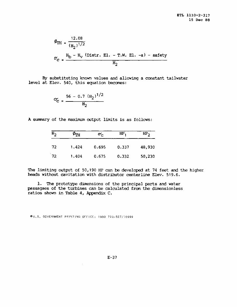
ETL 1110-2-31715 Dec 88
%= ‘2”08(H2)’/2
u= .Hb - ~ (Distr. El. - T.W. El. -a) - safety
H2
By substitutingknownvaluesand allowinga constanttailwaterlevelat Elev. 540,this equationk-s:
d= .56 - 0.7 (H2)’/2
Ha
A s~ of the Hirtu.lmoutputlimitsis as follows:
72 1.424 0.695 0.337 48,930
72 1.404 0.675 0.332 50,230
The limiting outputof 50,190~ can be devel~ at 74 feetand the higherheadswithoutcavitationwithdistr~tor centerlineElev. 519.6.
1. The prototypedtisions of the principalpartsand waterpassagaesof the turbinescan k calculatd franthe dimensionlessratiosshownin Table 4, ~ C.
*U.S. GOVERNMENT PRINTING OFFICE: 1990 720.527/10999
E-37