DISTRIBUTED COMMAND HANDLER WITH CORBA … a grant by Ericsson Utvecklings AB (UAB) in Älvsjö...
75
DISTRIBUTED COMMAND HANDLER WITH CORBA AND A COMPARISON OF SUCH A SYSTEM IN SOAP
-
Upload
nguyenngoc -
Category
Documents
-
view
238 -
download
3
Transcript of DISTRIBUTED COMMAND HANDLER WITH CORBA … a grant by Ericsson Utvecklings AB (UAB) in Älvsjö...

DISTRIBUTED COMMAND HANDLER WITH CORBA AND A COMPARISON OF SUCH A SYSTEM IN SOAP


Abstract The purpose of this Master’s project is to investigate the benefits of CORBA as a platform in command handler systems with regard to state management, memory utilization, security and performance. The theoretical part of this thesis consists of an extensive reading of the whole range of CORBA/SOAP specifications and literatures in the area of distributed systems, followed by implementation. The preliminary study on CORBA was conducted by myself and on SOAP by my colleague Yonas Ge-bremeskel.
These two implementations were then compared to give the decisive input. The con-clusion was that CORBA based solution is the overall best choice as a platform for command handler systems.
Referat Distribuerad kommandohantering med CORBA och en jämförelse av ett sådant system i SOAP.
CORBA och SOAP är två olika möjliga plattformar för användning i kommandohan-teringssystem. I detta arbete har en CORBA-baserad lösning undersökts med avseen-de på tillstånds- och minneshantering, säkerhet och prestanda. Arbetet har bedrivits i form av litteratur- och specifikationsstudier följt av implementation. Motsvarande arbete för SOAP har gjorts av Yonas Gebremeskel.
Dessa två lösningar har sedan jämförts för att utmynna i en slutlig rekommendation. Slutsatsen är att CORBA som plattform är överlägsen givet de ovannämnda kriterier-na.


Preface As a candidate of Master’s degree in Computer Science at the Department of Nu-merical Analysis and Computer Science (NADA) at Stockholm University from Feb-ruary to June of the year 2001, I and my colleage Yonas Gebremeskel decided to make a comparative study on CORBA and SOAP. The study was made possible through a grant by Ericsson Utvecklings AB (UAB) in Älvsjö under the supervision of Johan Flinck and Britt Classon of Ericsson.
The preliminary study on CORBA was conducted by myself and on SOAP by Yonas Gebremeskel. The result of the joint effort is attached herewith as a source material on which my project is partly based on.
The supervisor at NADA was Serafim Dahl and the examiner was Stefan Arnborg.
Acknowledgements I would like to thank Johan Flink, Britt Classon, Ayehou Mesfin, DR Aberra Jembere and Serafim Dahl for all their help and support with the manuscript and steering me in the right direction in the due process.

Contents
1 Introduction............................................................................................ 1 1.1 Background ...........................................................................................................1 1.2 Purpose..................................................................................................................1
2 Heterogeneous Distributed Systems ..................................................... 3 2.1 What is a distributed system?................................................................................3 2.2 Advantages of distributed systems ........................................................................3 2.3 Disadvantages of distributed systems....................................................................4 2.4 Design issues with distributed systems .................................................................6
2.4.1 Transparency .............................................................................................6 2.4.2 Reliability ..................................................................................................7 2.4.3 Performance...............................................................................................7 2.4.4 Scalability ..................................................................................................8
3 Distributed System Technologies.......................................................... 9 3.1 Remote Procedure Calls (RPC) ...........................................................................10 3.2 Remote Method Invocation (RMI)......................................................................10
3.2.1 RMI architecture overview......................................................................11 3.3 Simple Object Access Protocol (SOAP) .............................................................11
3.3.1 What is SOAP?........................................................................................11 3.3.2 SOAP Architecture ..................................................................................11 3.3.3 Example of a SOAP call ..........................................................................13 3.3.4 Example of a SOAP response..................................................................15 3.3.5 Firewall and SOAP..................................................................................16 3.3.6 Advantages of SOAP...............................................................................16 3.3.7 Disadvantages of SOAP ..........................................................................16
3.4 Distributed Component Object Model ................................................................17
4 Common Object Request Broker (CORBA) ..................................... 18 4.1 What is CORBA? ................................................................................................18 4.2 Object management architecture (OMA) ............................................................18
4.2.1 Core object model....................................................................................19 4.2.2 Reference model ......................................................................................19 4.2.3 Application interfaces..............................................................................19 4.2.4 Common facilities (CORBAfacilities).....................................................19 4.2.5 Object services (CORBA services) .........................................................20
4.3 Object request broker (ORB) ..............................................................................22 4.3.1 Location transparency..............................................................................22 4.3.2 Language independence ..........................................................................22 4.3.3 Platform-independence ............................................................................23
4.4 IIOP + IOR = Interoperability ............................................................................25 4.5 Interface definition language (IDL).....................................................................26 4.6 How dose CORBA work? ...................................................................................27 4.7 CORBA on the client side ...................................................................................27 4.8 CORBA on the server side ..................................................................................28 4.9 Portable Object Adapter (POA)...........................................................................30
4.9.1 Design goals of POA ...............................................................................31 4.9.2 RootPOA .................................................................................................32 4.9.3 POA manager ..........................................................................................32 4.9.4 POA policies............................................................................................34 4.9.5 Servant managers.....................................................................................34

4.10 CORBA Security.................................................................................................34 4.10.1 Security primer ........................................................................................34 4.10.2 Security problem with distributed objects ...............................................36 4.10.3 CORBA security services (CORBAsec)..................................................37 4.10.4 Overview of CORBA security.................................................................37 4.10.5 CORBA and firewall ...............................................................................39 4.10.6 Applet and CORBA.................................................................................43
5 AXE Structure and Basics................................................................... 44 5.1 AXE Architecture................................................................................................44 5.2 AXE Hierarchy....................................................................................................44 5.3 APG 40................................................................................................................45 5.4 Man Machine Language......................................................................................45
6 Implemented Solution.......................................................................... 47 6.1 Used hard- and software......................................................................................47 6.2 Prototype .............................................................................................................47
6.2.1 Client .......................................................................................................48 6.2.2 Server.......................................................................................................48 6.2.3 PrototypeROS..........................................................................................49
6.3 Client server interaction ......................................................................................50
7 Results ................................................................................................... 55 7.1 CORBA performance ..........................................................................................55 7.2 Memory management..........................................................................................55 7.3 State management ...............................................................................................57
8 Comparison of SOAP and CORBA.................................................... 58 8.1 Performance ........................................................................................................58 8.2 Memory Management .........................................................................................59 8.3 State management ...............................................................................................61
9 Conclusions ........................................................................................... 62
Abbreviations ............................................................................................. 63
Bibliography ............................................................................................... 64

List of figures Figure 1.1 Architectural overview. ....................................................................................2 Figure 3.1 SOAP message [6]. .........................................................................................12 Figure 3.2 Example of a SOAP call [8]. ..........................................................................14 Figure 3.3 Example of a SOAP Response [8]. .................................................................15 Figure 4.1 Object Management Architecture (OMA) [15]. .............................................18 Figure 4.2 The Structure of CORBA 2.0 ORB source [15]. ............................................24 Figure 4.3 IIOP layers. .....................................................................................................25 Figure 4.4 Active Object Map..........................................................................................29 Figure 4.5 POA Architecture Source [22]........................................................................32 Figure 5.1 General syntax of MML. ................................................................................46 Figure 6.1 The prototype architecture. .............................................................................47 Figure 6.2 The implemented CORBA solution................................................................48 Figure 6.3 Design of PrototypeROS. ..............................................................................49 Figure 6.4 Initiates applet and get ROS from CORBA name services.............................51 Figure 6.5 Synchronous session. ......................................................................................52 Figure 6.6 Sending a MML commando in a synchronous session. ..................................53 Figure 6.7 Retrieving a result printout in a synchronous session.....................................54 Figure 7.1 Task manager of Windows showing memory usage.......................................56

List of tables Table 1 CORBA Services. ...........................................................................................21 Table 2 Interface names and there description.............................................................50 Table 3 Performance result. .........................................................................................55 Table 4 Memory consumption. ....................................................................................57 Table 5 Performance result of the two prototypes. ......................................................58 Table 6 Comparison of memory usage in the two prototypes......................................60
1
1 Introduction
In order to understand the background and the purpose of this Master’s thesis a brief explanation of the problem is given in this chapter.
1.1 Background The division Unit Element Management at Ericsson Utecklings AB (UAB) mission is to provide ease of use and open element management interfaces for UAB platforms in order to minimize the cost of ownership for Ericsson’s customers.
The management tools are used for installation, testing and maintenance of ex-changes such as AXE. These tools are often used remotely, i.e. running on a different machine than the exchanges. The tools may therefore communicate with the ex-changes in a client/server system such as X.29, Telnet, LDAP, etc. They are used for communication between the applications and the exchange.
Towards the end of 2000 the Unit Element Management announced a Master’s pro-ject in order to:
1. Implement a prototype for a commando handler system.
2. Investigate SOAP and CORBA’s usability in such applications.
3. Compare the advantages and constraints of these two technologies.
The user of the commando handler system is usually an operator that wants to con-figure and manage an AXE exchange by sending special commands called Man-Machine Language (MML). In order to perform operations and access information, the operator is required to provide some username (Id) and password.
1.2 Purpose The purpose of this Master’s project is to investigate if CORBA or SOAP is more suitable for distributed management tools (commando handler system).
The investigation will be done with regarding to state management, memory con-sumption, security and performance.
• State management – It is very important to be able to send several commands in one session. Additionally there are several modes of the MML commands and the system must remember previously executed commands.
2
• Memory consumption – The command handler system will be installed in a machine called APG40. APG40 is used to send commands from a client to the AXE and the result (printouts) of the commands will be sent back to the client through APG40. High availability (about 99.8 % per year) is very critical for APG40. Thus the command handler system should not consume much memory.
• Security – the command handler system will have to let only certain users (such as operator) to send command to configure the AXE exchange.
• Performance – The response from the commands have to arrive to the clients in a few seconds.
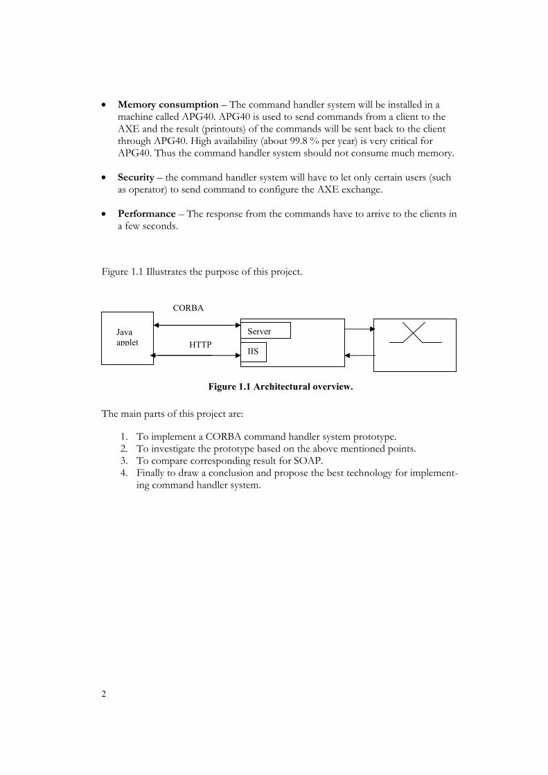
Figure 1.1 Illustrates the purpose of this project.
Figure 1.1 Architectural overview. The main parts of this project are:
1. To implement a CORBA command handler system prototype. 2. To investigate the prototype based on the above mentioned points. 3. To compare corresponding result for SOAP. 4. Finally to draw a conclusion and propose the best technology for implement-
ing command handler system.
(JA APG
CORBA
HTTP Java applet
IIS
Server

3
2 Heterogeneous Distributed Systems
An important characteristic of large computer networks such as Internet and corpo-rate Intranet is that they are heterogeneous. For example, a corporate Intranet might be made up of:
• Different hardware’s: PC, servers, mainframes and workstations.
• Different software’s (OS): various flavors of Microsoft Windows and XP or NT, UNIX, Apple Macintosh, Linux, IBM OS/2.
• Different Mobile devices: Palm or smart phones.
• Different network and network protocols: Ethernet, FDDI, ATM, TCP/IP, Novell NetWare, blue tooth or even microwaves and communication satellites.
The increasing complexity of these networks is due to the need to share information and resources with in and across diverse part of a computing enterprise.
2.1 What is a distributed system? “In a distributed system the existence of multiple autonomous1 computers is trans-parent, i.e. not visible to the user. The user can type a command to run a program, and it runs”. The Operating System selects the best processor, find and transport all inputs to the processor, and put the result in appropriate place. The user of a distrib-uted system is not aware that there are multiple processors [1].
2.2 Advantages of distributed systems Few of the reason for using a distributed system instead of having a huge centralized system are [1]:
1. Economics The collection of processors provides a higher performance and a better price/performance ratio than a single centralized system.
A combination of cheap processors is often more cost-effective than one expensive fast system.
2. Sharing of data and resources.
1 Computers, which, in pr inciple , could work independently .

4
3. Speed A distributed system may have more total computing power than a mainframe.
4. Incremental growth It is possible to add more processors and machines to the system, as requirement on processing power grows.
5. Reliability Reliability comes in two flavors, availability (if one or more machines go down, the system, as whole should continue working) and fault-tolerance (the system de-tects fault and handle them in a proper way).
2.3 Disadvantages of distributed systems Distributed application developers face many challenges and must address a number of issues that can be taken for granted in a local program where all logic executes in the same operating system process. Distributed application developers have to solve numerous of difficult and complex problem such as [1]
• Difficulty of developing distributed software.
• Communication problems.
• Security problems.
• Independent failures of processors.
• Transparent and uniform access to data.
Difficult to develop distributed software
Distributed software is hard to develop, design, debug and manage. Distributed sys-tems have distributed state, computation and operate over multiple computers and communication nodes.
Communication problems
Networks are needed to connect independent machines. Several problems are created by the network infrastructure such as performance limits and point of failure (com-munication break up, loss of messages etc).

5
Security problems
Distributed systems are vulnerable to security attacks because information is commu-nicated and processed on many machines, without having much control over them.
Performance
Communication between objects in the same process is faster than communication between objects on different machines.
Partial failures
When two objects are co-located, they fail together i.e. if the process in which they execute fails, both objects fail. But if two objects are distributed across process boundaries, the objects can fail independently. Distributed system developers need a way to adapt gracefully in the face of partial failures.
Concurrent access
In single threaded programming objects are accessed in a well-defined sequential or-der according to the program’s algorithms, and need not to be concerned with con-current access. But with multiple threaded programming, one must consider the pos-sible orderings of access to objects and use synchronization mechanisms to control concurrent access to shared objects.
Memory Access
Remote memory access is not the same as local memory access. Local pointers are meaningless outside the address space of the process.

6
2.4 Design issues with distributed systems Before implementing a distributed system application there are several conflicting design issues one must consider such as
• Some distributed system applications can only be run on specific machines or at specific locations.
• Smaller distributed system applications increase flexibility of deployment, but they also increase network traffic.
• Larger distributed system applications reduce network traffic, but they also reduce flexibility of deployment.
There are a lot of challenges that must be addressed in the design of distributed sys-tems. Distributed system application developers will face some of these challenges over and over again. Here is a brief explanation of these challenges [1].
2.4.1 Transparency
Transparency is about how to achieve the single system image, how to fool everyone into thinking that the collection of machines is a single computer [1]. Transparency is a strong property that is difficult to achieve. Transparency can be achieved in two different levels.
1. By hiding the distribution from the user.
2. By hiding the distribution from the program.
There are a number of different forms of transparency. These are the most essential ones
• Location transparency: users should not be required to know the physical loca-tion of resources.
• Access transparency: users should access a resource in an identical way whether the resource is local or remote.
• Migration transparency: resources can migrate (move from one location to an-other) without changing their names.
• Replication transparency: users should be unaware of the existence of multiple copies of the same resource.

7
• Concurrency transparency: Users should be unaware of the existence of other users in the same system even if they access the same resources.
• Failure transparency: refers to that applications should be able to complete their tasks even if failures occur in certain part of the system, without the user knowledge.
• Parallelism transparency: Users should be unaware of parallel execution of ac-tivities.
• Performance transparency: allows the system to be reconfigured to improve performance as loads vary.
There are a few more types of transparency that a designer has to consider, such as invocation transparency, machine type, operative system, programming language transparency, etc.
2.4.2 Reliability
Reliability is an important issue in distributed system, and requires availability, consis-tency and fault tolerance [1].
Availability
Availability is a proportion of time in which service is accessible to users. The idea behind availability is that if one machine in the distributed system goes down, some other machine will take over the job without the users knowledge. The system must not lose data when the changing takes place.
Fault tolerance
Fault tolerance is about how a system should react when it detects a fault. One can-not achieve high reliability without some way to detect faults and handle them.
2.4.3 Performance
All systems should be built to achieve maximal performance. To get a high perform-ance is a challenging point in distributed systems because of it conflicts with other desirable properties that have been tried to achieve so far, such as transparency, mi-gration and reliability. The overall performance of a distributed system depends on the performance of individual workstations, the speed of the communication infra-structure, the reliability (fault tolerance) used and the workload allocation.

8
2.4.4 Scalability
The main goal with scalability is to build distributed systems that scale with the in-creased number of users, CPU’s and resources connected etc, without performance loss. Incremental scalability should be transparent to clients and easy to add new re-sources. Avoiding any form of centralized resources gives high scaleable systems [1].

9
3 Distributed System Technologies
There are several distributed system technologies in the market today. Some of the essential ones are:
Remote Procedure Call (RPC)
Remote procedure call (RPC) is a common method of communication in distributed applications because of their familiar procedure-style semantics. There are two RPC implementations:
1. SUN RPC.
2. Distributed Computing Environment (DCE) RPC.
Remote Method Invocation (RMI)
RMI is a technology developed by Sun to write distributed objects using the java en-vironment. Because RMI is centered on Java, it brings the power of java safety and portability to distributed computing.
Simple Object Access Protocol (SOAP)
Microsoft, DevelopMentor, and Userland Software originally developed SOAP, and it was thereafter submitted to the Internet Engineering Task Force (IETF). SOAP uses two existing and widely deployed protocols: HTTP and XML. SOAP uses XML as its data encoding and HTTP as a mean of transport. SOAP defines a mechanism to pass commands and parameters between HTTP clients and servers.
Distributed Component Object Model (DCOM)
DCOM is an extension of component object model (COM). DCOM was developed by Microsoft and has been submitted to the IEFT as a draft standard.
Common Object Request Broker Architecture (CORBA)
CORBA is an industry-wide standard for creating distributed object systems. CORBA is short for Common Object Request Broker Architecture. CORBA enables invoca-tion of methods on distributed objects residing anywhere on a network, just as if they were local objects.

10
3.1 Remote Procedure Calls (RPC) RPC is a simple and powerful technique for constructing distributed client-server-based applications. The idea behind RCP is to make remote procedure call look as much as possible like a local one [1]. The calling procedure should not be aware that the called procedure is executing on a different machine it should be transparent. By using RPC, a developer of distributed applications avoids the details of underlying communication with the network. As far as the application developer is concerned, invoking a remote procedure is not very different from invoking an ordinary local procedure call. The run-time system providing the RPC mechanism handles all the underlying communication to make things look simple to the application programmer [2].
When the client makes an RPC, it provides the values of the parameters. The run-time system then contacts the location server to establish a binding between the client and the server. Once the connection is made, the parameter values are marshaled (packed for transmission) by the client stub and sent as a message to the server. Upon receipt of these messages, the server stub demarshals (unpacks) the parameters and calls the procedure using the parameter values that were sent by the client. Finally, the return value is marshaled by the server stub and sent back to the client, where it is demarshaled by the client stub and used as the return value from the procedure call.
What is Marshaling?
Marshaling is about translating the parameters into a format that can be transmitted across the network to the remote call. (This is sometimes referred to as an on-the-wire format). Unmarshaling is the reverse of marshaling; converting them from the on-the-wire format into a format that the calling method understands.
3.2 Remote Method Invocation (RMI) Before RMI, sockets were the only facility built into the java programming language that provided direct communication between machines. RMI abstracts the socket connectivity and data streaming. RMI enables objects in one java virtual machine to invoke methods on objects in a remote virtual machine; the purpose is to make ob-jects in separate virtual machine look and act like local objects [3].
A typical server application creates some remote objects, makes references to them accessible, and waits for clients to invoke methods on these remote objects. A client can call a remote object in a server once it obtains a reference to that object, as if it were a local object running on the same virtual machine as the server, and that server can also be a client of other remote objects [4]. RMI hides the underlying mechanism of transporting method arguments and return values across the network.

11
3.2.1 RMI architecture overview
The RMI system consists of three layers [5] the stub/skeleton layer (Client-side stubs and server-side skeletons), the remote reference layer (RRL) and the transport layer. The client code will first talk to its stub, which then sends the message to the remote RRL. The RRL then passes it through the transport layer to the server machine. At the server, the massage goes all the way up again. The transport layer passes it to the server RRL, which in turn retranslates it to the skeleton where it finally appears at the server’s object implementation.
3.3 Simple Object Access Protocol (SOAP) SOAP is a lightweight specification protocol used to invoke methods on servers, components and objects to exchange information in a distributed environment and it acts as the glue between heterogeneous software components.
3.3.1 What is SOAP?
SOAP uses XML as an encoding scheme for request and response parameters and use HTTP for transport. A SOAP method is a HTTP request and response that complies with the SOAP encoding rules. SOAP is a protocol that defines how to access services and servers in a platform-independent manner using HTTP and XML. SOAP does not care what operating system, or programming language is being used on either the server side or the client side [6].
Why HTTP and XML?
HTTP is a well-understood technology and this makes HTTP a good choice for transport mechanism. XML is becoming as important as HTTP. XML is a simple and extensible text markup language. Since XML is just text, any application can under-stand it. Combining HTTP and XML into a single solution gives (HTTP + XML = SOAP) [6].
3.3.2 SOAP Architecture
The main point behind SOAP is to “first invent no new technology” [7]. The authors of the specification explicitly exclude of building anything that is already been built. SOAP is a lightweight specification protocol used to invoke methods on servers and components to exchange information in a decentralized, distributed environment. This XML-based protocol can be broken down into three parts [8]:

12
1. The structure of the SOAP envelope (Payload) defines a general structure ex-pressing the content.
2. The SOAP encoding rules define a serialization mechanism that can be used to exchange instances of application-defined data types.
3. SOAP’s remote protocol call defines a convention, which can be used to rep-resent remote procedure calls and their responses.
The XML part of every SOAP message contains particular tags and attributes as seen in Figure 3.1. They are:
• The SOAP envelope: this is the first element in the XML document representing the message. It is mandatory and it contains the name of the element (envelope), followed by a namespace defining the SOAP version being used and the optional encoding Style attribute which points to a link where the serialization and encod-ing rules are defined.
• The (optional) SOAP header: is used to encapsulate extended information about the call. This information is user-defined, and its content depends on what you want to achieve.
• The SOAP body: is a container for the mandatory information being sent to the message endpoint. It contains the actual method call. The SOAP body clearly marks the separation of SOAP metadata and data.
Figure 3.1 SOAP message [6].
HTTP Header Post / ObjectURI HTTP/1.1 SOAPMethodname
SOAP Envelope
SOAP Header
SOAP Body
Element
Element

13
SOAP defines two types of messages, Call and Response, to allow clients to request a remote procedure and to allow servers to respond to such requests.
3.3.3 Example of a SOAP call
SOAP defines call methods to allow clients to request a remote procedure. The layout of the SOAP call will be illustrated in Figure 3.2.
The HTTP header is found just before the SOAP message. The HTTP protocol sends a POST request via the network. The first four lines found below are standard HTTP:
1.POST /StockQuote HTTP/1.1 2.Host: www.stockquoteserver.com 3.Content-Type: text/xml 4.charset="utf-8" 5.Content-Length: nnnn POST is the HTTP verb, /StockQuote is a URI request and HTTP/1.1 is a protocol been used and its version.
Host is required for all HTTP messages and it gives the target site (www.stockquoteserver.com).
Content-Type, charset and content-Length used to define the MIME format for mes-sage display. They are required for all HTTP messages that contain a payload.
1. The Content-Type “text/xml” indicates that the payload is an XML message to the server.
2. The charset is the HTTP coding
3. The Content-Length is the length of the message.

14
POST /StockQuote HTTP/1.1 Host: www.stockquoteserver.com Content-Type: text/xml Charset="utf-8" Content-Length: nnnn SOAPAction: Some-Namespace-URI#GetLastTradePrice <SOAP:Envelope xmlns:SOAP="urn:schemas-xmlsoap-org:soap.v1"> <SOAP-ENV:Header> <t:Transaction xmlns:t="some-URI" SOAP-ENV:mustUnderstand="1"> ..... </t:Transaction> </SOAP-ENV:Header> <SOAP:Body> <m:GetLastTradePrice xmlns:m="Some-Namespace-URI"> <symbol>DIS</symbol> </m:GetLastTradePrice> </SOAP:Body> </SOAP:Envelope>
Figure 3.2 Example of a SOAP call [8]. SOAPAction: Some-Namespace-URI#GetLastTradePrice The SOAPAction determines the intention of the HTTP request. The identifier fol-lowing the # sign must match the name of the first tag in the SOAP message body. This header is intended for firewalls and other network infrastructure that are aware of SOAP, especially for filtering and routing purposes. The value is a URI that identi-fies the action requested by this message. A HTTP server receiving this message knows that it is a SOAP message because it recognizes the HTTP header SOAPAc-tion.
<SOAP:Envelope xmlns:SOAP="urn:schemas-xmlsoap-org:soap.v1"> <SOAP-ENV:Header> <t:Transaction xmlns:t="some-URI" SOAP-ENV:mustUnderstand="1"> ..... </t:Transaction> </SOAP-ENV:Header> <SOAP:Body> <m:GetLastTradePrice xmlns:m="Some-Namespace-URI"> <symbol> LSE </symbol> </m:GetLastTradePrice> </SOAP:Body> </SOAP:Envelope>

15
The elements Envelope and Body provide a generic payload packaging mechanism; the element <GetLastTradePrice> contains an element called <symbol>, which con-tains a stock ticker symbol. The purpose of this request is to get the last trading price for a specific stock in this case Ericsson (LSE).
3.3.4 Example of a SOAP response
The layout of the SOAP response is identical to the call request with the exception that here the return value is returned in the body section [8] as seen in Figure 3.3.
HTTP/1.1 200 OK Content-Type: text/xml Content-Length: nnnn <SOAP:Envelope xmlns:SOAP="urn:schemas-xmlsoap-org:soap.v1"> <SOAP:Body> <m:GetLastTradePriceResponse xmlns:m="Some-Namespace-URI"> <return>67</return> </m:GetLastTradePriceResponse> </SOAP:Body> </SOAP:Envelope>
Figure 3.3 Example of a SOAP Response [8]. HTTP/1.1 200 OK Content-Type: text/xml Content-Length: nnnn The first three lines are, again, standard HTTP: the first line indicates a response code to the previous POST request, the second and third lines indicate content type and length.
<SOAP:Envelope xmlns:SOAP="urn:schemas-xmlsoap-org:soap.v1"> <SOAP:Body> <m:GetLastTradePriceResponse xmlns:m="Some-Namespace-URI"> <return>34.5</return> </m:GetLastTradePriceResponse> </SOAP:Body> </SOAP:Envelope>

16
The XML element, <GetLastTradePriceResponse>, contains a response to the re-quest for a trading price; its child element is <return>, which indicates the value, to return to the request. The response element name is merely the request element with “Response” appended.
The basic idea is that client code should resemble the simplicity of making a simple function call on another server. SOAP provides only single function or method invo-cations, which mean that you, cannot maintain the state to an object between calls. With SOAP, the client makes single method or function calls, one per HTTP request. The SOAP model follows standard web application stateless transactions with dis-connected data. You will be forced to program stateless objects, as all state informa-tion is lost from call to call.
3.3.5 Firewall and SOAP
Most firewalls block all but a few ports, such as the standard HTTP port 80, most distributed object protocols suffer because they rely on dynamically assigned ports for remote method invocations. If the system administrator opens a range of ports through the firewall, it is possible to get around this problem as long as the ports used by the distributed object protocol are included.
Since SOAP relies on HTTP as the transport mechanism, and most firewalls allow HTTP to pass through, there is no need to make any special accommodations on routers, firewalls, or proxy servers for SOAP to work.
3.3.6 Advantages of SOAP
• SOAP uses HTTP and therefore it can take advantage of the HTTP features like encryption and authentication as well as having the benefit of going through the enterprise firewall.
• SOAP is a simple protocol that is easy to implement and work with.
• SOAP can be implemented in any language, as long as the client sends a valid SOAP request.
3.3.7 Disadvantages of SOAP
• Existing implementations are not satisfactory (SOAP is still in its early age).
• Soap is stateless.

17
• SOAP does not address higher-level issues such as object activation or lifetime management.
3.4 Distributed Component Object Model COM defines how components and their clients interact. A client that needs to com-municate with a component in another process cannot call the component directly, but has to use some form of interprocess communication provided by the operating system. COM provides this communication and it intercepts calls from the client and forwards them to the component in another process.
Distributed COM (DCOM) is the big brother of COM. The definition of “distrib-uted” is that it is able to run clients and servers in different processes across an intra-net or Internet. DCOM works just like COM: a client asks where the server is located and, instead of pointing it to someplace on the local machine, it points to an IP ad-dress.
The primary difference between using COM and DCOM is that COM processes run on the same machine in different address spaces, but DCOM processes are spread across a network. That is why DCOM is often called COM on the wire [9].
Location transparency
Location transparency is achieved in DCOM using the proxy/stub architecture. The proxy serializes all parameters, which may be very complex structures, into a stream of bytes that can be transported across the network. The stub unmarshals the stream to recreate the parameter’s structures, which the server procedure uses to process the call.
Language independence
As an extension of COM, DCOM is completely language-independent.
18
4 Common Object Request Broker (CORBA)
The object management group (OMG http://www.omg.org) developed CORBA; OMG was founded by a group of commercial vendors in 1989. The OMG comprises over 800 companies and organizations. OMG releases specifications for the Common Object Request Broker Architecture (CORBA) and other related technologies. The OMG writes no software; it only facilitates the definition of standards.
4.1 What is CORBA? CORBA is an industry-wide standard for creating distributed object systems. CORBA defines how distributed objects can interoperate. CORBA is the heart of the OMG’s architectural framework, the Object Management Architecture (OMA) [11].
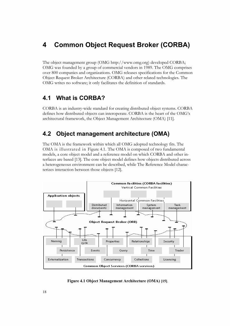
4.2 Object management architecture (OMA) The OMA is the framework within which all OMG adopted technology fits. The OMA is i l lustrated in Figure 4.1. The OMA is composed of two fundamental models, a core object model and a reference model on which CORBA and other in-terfaces are based [13]. The core object model defines how objects distributed across a heterogeneous environment can be described, while The Reference Model charac-terizes interaction between those objects [12].
Figure 4.1 Object Management Architecture (OMA) [15].

19
4.2.1 Core object model
The Core Object Model does not constrain the syntax of object interfaces or imple-mentation of objects. The main goals of the Core Object Model are portability and interoperability. This means being able to invoke operation on objects regardless of where they are located, which platform they execute on, or what programming lan-guage they are implemented in. The Object Model defines how distributed objects are described [14].
4.2.2 Reference model
The reference model is directly relevant to CORBA programmers because it provides which components and frameworks can support developers of distributed applica-tions [14].
4.2.3 Application interfaces
Application interfaces are developed specifically for a given application and are not standardized. When they are broadly accepted and used in a specific domain they become a vertical facilities.
4.2.4 Common facilities (CORBAfacilities)
Common facilities are those end-user-oriented interfaces that provide facilities across application domains and facilities provide standards for services aimed at application [16].
CORBAfacilities
CORBAfacilities provides higher-level functionality at the application level. COR-BAfacilities cover both horizontal facilities (features useful to all types of CORBA applications across various industries) and vertical facilities (functionality that is espe-cially useful to applications within particular vertical markets and industries).

20
Horizontal facilities
The horizontal CORBAfacilities are categorized into four types of facilities: user in-terface, information management, systems management, and task management. These categories are further broken down into other facilities [17].
Vertical facilities
Vertical facilities are domain-based and provide the functionality for a specific do-main such as telecommunication, electronic commerce, financial, manufacturing, or healthcare.
4.2.5 Object services (CORBA services)
Object services are the building blocks from which other components of OMA can be constructed. The object services offer fundamental services for developers. Such services include store objects, manage objects, locate objects, create objects, naming objects, controlling access to objects and keeping track of relocated objects. OMG has published standards for object services and some of them are explained below in Table 1 [18].

21
Table 1 CORBA Services.
Service Description
Naming Service A naming service allows a CORBA client to locate a named CORBA object.
Life Cycle Service The life cycle service defines how CORBA objects are created removed, moved, and copied.
Concurrency control Service
Concurrency control service defines how an object mediates simultaneous accesses by one or more clients.
Transactions Service The transaction service provides the interfaces to support transaction capabilities.
Persistent object Service (POS)
Persistent object service provides a common interface for the mechanisms used for retaining and managing the persistent state of objects in a data-store independent manner.
Security Service Security service will be investigated more closely later.
Time Service The Time Service enables the user to obtain the current time together with an error estimate with it.
Trader Service
The Trader Service supports the finding of CORBA objects like the naming service but rather than use a name to locate an object, it looks up an object based on properties describing the service offered by the object.

22
4.3 Object request broker (ORB) The ORB is the most important piece of the OMA; it is heart of any CORBA imple-mentation. The ORB is the software that implements the CORBA specification. The ORB is the only portion of CORBA that must be present in order to build a CORBA-compliant application. A CORBA application cannot function without the ORB.
The role of the ORB is to hide the underlying complexity of network communica-tions from the programmer [19]. The ORB locates the remote object on the network and ensures that
1. It is ready to receive the request.
2. It communicates the request to the object.
3. It waits for the results and returns the results back to the client.
Another responsibility of the ORB is to receive the input parameters from the com-ponent that is calling the method and to marshal these parameters. The ORB per-forms the entire process of marshaling input parameters, initiating the method invo-cation on the server, and unmarshaling the return parameters automatically and transparently.
The ORB gives location transparency, language independence, and platform-independence.
4.3.1 Location transparency
To invoke an object with CORBA, the client object only needs a reference to the server that it wants to communicate with. The client uses exactly the same request mechanism regardless of where the server is located. They might be in the same pro-cess or across a network. The client cannot tell the difference. As far as the client is concerned a result is returned (or an exception is raised).
One CORBA object never talks directly with another. Instead, the object requests for an interface to the ORB running on the local machine. The local ORB then passes the request to an ORB on the other machine. Thereafter the remote ORB locates the appropriate object and passes back an object reference to the requester [10].
4.3.2 Language independence
A client issuing the request can be written in a different programming language from the implementation of the CORBA object (server). In other words, a client written in java (java can run on virtually any type of machine) can communicate with a server

23
written in C++ (C++ gives high performance), which in turn can communicate with another server written in COBOL (for backward compatibility), and so forth. Lan-guage independence is important feature of CORBA; it gives developers the freedom to choose the language that best suits their needs.
CORBA achieve language independency by separating interface from implementation and provides language-neutral data types that make it possible to call objects across languages. The separation between an object’s interface and its implementation has several advantages. For example, it allows you to change the programming language in which a server object is implemented without changing clients that access the ob-ject.
4.3.3 Platform-independence
The major benefit offered by the ORB is its platform-independent treatment of data. This means that a client running on, for instance a Macintosh system or any of Mi-crosoft’s operating systems can invoke methods on a server running on an UNIX system or vice versa. CORBA makes it possible to run an object from the platform that makes the most sense for that object.
In short the ORB hides: • Object location: the client does not know where the target object resides.
• Object implementation: the client does not know how the server object is im-plemented or what programming language it was written in.
• Object execution state: the client does not know whether the server is cur-rently activated and ready or deactivated.
• Object communication mechanism: The client does not know what commu-nication mechanism is used.
The ORB responsibilities are: • Given an object reference from a client, the ORB locates the corresponding
object implementation (server) on behalf of the client.
• When the server is located, the ORB ensures that the server is ready to re-ceive the request.
• The ORB on the client side accepts the parameter of the method being in-voked and marshals the parameters to the network. The ORB on the server side unmarshals the parameters from the network and delivers them to the server.
• The ORB returns the result/error from the server to the client side ORB.

24
A number of ORB implementation exist in the market today, including VisiBroker from Inprise (Borland http://www.inprise.com), ORBIX from IONA Technologies ( http://www.iona.com) and JavaIDL from JavaSoft (http://www.javasoft.com).
Since there is more than one CORBA implementation and these implementations are from different vendors, they need a way to communicate with each other. The solu-tion of this problem was the new CORBA 2.0 Specification. The primary goal of CORBA 2.0 (see Figure 4.2) was to define a standard protocol by which ORBs from various CORBA vendors could communicate (interoperability across ORBs). This protocol is known as the Internet Inter-ORB Protocol (IIOP which is based on TCP/IP).
Figure 4.2 The Structure of CORBA 2.0 ORB source [15].

25
4.4 IIOP + IOR = Interoperability IIOP arises from the problems caused by communication over heterogeneous net-works. With CORBA 1.0, the OMG left it up to the vendors to implement a protocol for their ORBs and objects to use over a network, instead of mandate a particular data format or protocol for ORB communications, due to that ORBs could not communicate with one another. The CORBA 2.0 specification provides the method-ology ORBs need to communicate. This is known as the ORB Interoperability Archi-tecture and more specifically the General Inter-ORB Protocol (GIOP). The GIOP, written by the OMG, is a collection of message requests ORBs can make over a net-work. ORB Interoperability allows a client of one vendor ORB to invoke operations on an object in a different ORB.
GIOP implementation that all ORBs must be able to use is the Internet Inter-ORB Protocol (IIOP). IIOP maps GIOP messages to TCP/IP (GIOP + TCP/IP = IIOP). IIOP uses the Internet as backbone. IIOP ensures true interoperability among prod-ucts from numerous vendors, thus enabling CORBA applications to be more vendor-independent.
As of the 2.0 version of the CORBA specification, vendors are required to implement the IIOP protocol in order to be considered CORBA-compliant. IIOP runs on top TCP/IP on the application layer as illustrates in Figure 4.3. IIOP allows state data to be preserved across multiple invocations of objects and across multiple connections.
Application Ob-jects
ORB
IIOP
TCP0
IP
Ethernet
Physical Device
Figure 4.3 IIOP layers.
CORBA specifies a standard object reference format called Interoperable object ref-erence (IOR). An IOR specifies the wire protocol for talking to an object, as well as specifying the object’s network location. IORs are convenient because they are easy

26
to use and ORB-implementation-independent. An IOR contains the information required for a client ORB to connect to a CORBA object. The IOR is defined in such a way that any vendor’s ORB can accept an IOR and resolve it, yielding the object’s location. Because IOR are plain strings, they are easily transmitted across a network, stored in a file, etc.
What is inside a CORBA object reference (IOR)?
Type name (Repository ID): this is an optional field that serves as an index into interface repository to identify interface.
Protocol and address details: This field identifies a transport endpoint and specifies a protocol and the addressing information appropriate for that protocol. In this case IIOP, the addressing information consists of a
• IIOP version describes the IIOP version implemented by the ORB.
• Host name: identifies the TCP/IP address of the ORB’s host machine.
• TCP port number: specifies the TCP/IP port number where the ORB is listening for client requests.
• Time Stamp: the information in this filed is used ensure uniqueness for IORs.
Object key: the information in this field is binary data, property to the ORB that created the IOR. The Object Key internally consists of two components, the object adapter name and an Object ID.
4.5 Interface definition language (IDL) One of the keys to success in developing application in heterogeneous distributed system is to separate interfaces from their implementations [20].
IDL is used to describe the interfaces between CORBA objects. The interface defini-tion specifies which member functions are available to a client, without making any assumptions about the implementation of the object [20]. The interface serves as a contract between clients and servers [10].
IDL is not an implementation language it is a declarative language. The purpose of IDL is to define interfaces; providing implementations for these interfaces are per-formed using some other programming language.
From IDL definition, the CORBA objects are mapped to any programming language; because of IDL CORBA applications are independent of the language(s) used to im-plement them. IDL achieves language independence through the concept of language

27
mapping. Some of programming languages with IDL mapping includes Java, C, C++, Smalltalk Ada, Cobol and Lisp.
4.6 How dose CORBA work? The IDL compiler generates as client stubs and server skeletons. A client stub is a mechanism that creates and issues requests on behalf of a client, the client stub methods simply communicate with the ORB to marshal and unmarshal parameters. A skeleton is a mechanism that delivers requests to the CORBA object implementation (server) [10].
Below you can find a description of a CORBA interaction on the client and server side [10].
Client side
1. The client object invokes a CORBA call and contacts the stub that represents the server which the client wants to communicate.
2. The stub marshals the arguments provided to the operation and pass them to the underlying ORB on the client machine.
3. The ORB determines if the server is in the same machine or not. If the server is in the same machine the ORB contacts the appropriate skeleton. If the server is not in the same machine the ORB determines the location of the destination object ORB and call the server-object through the server’s ORB.
Server side
1. The server side ORB invokes the appropriate skeleton.
2. The skeleton unmarshalls the arguments send to the server.
3. The server returns the result back to the client in the similar fashion.
4.7 CORBA on the client side The following is a short introduction to the different parts of CORBA on the client side.
Client IDL stubs
A CORBA IDL compiler automates the transformation between CORBA IDL defi-nitions and the target programming language. The stub is actually wired into the

28
ORB, so that calling it invokes the ORB, which forwards the invocation to the server. The stub works directly with the client ORB to marshal the request [10].
Interface repository (IR)
The interface repository is a service that provides persistent objects that represent the IDL information in available form at runtime.
Dynamic invocation interface (DII)
The ORB DII allows dynamic creation and invocation of requests to objects. Clients use the DII to dynamically issue requests to objects without requiring IDL interface-specific stubs. The client can dynamically specify an object, operation and set of pa-rameters. This information is usually retrieved from the interface repository [10].
4.8 CORBA on the server side The following is a short introduction to the different parts of CORBA on the server side.
Server skeletons
An IDL compiler generates the server skeleton like the client stubs. The server skele-ton provides a static interface to each service exported by the server. On the server side, the ORB uses skeleton code to translate the remote invocation into a method call on the local object. Once the object completes the request, any response is sent back the way it came.
ORB Interface
The ORB interface consists of a few helper functions that go directly to the ORB and are not passed to the object implementation. The helper function includes converting object references to string and vice versa and allows test if a specific object currently is in use on the ORB [10].
Dynamic skeleton interface (DSI)
The dynamic skeleton interface is a way to deliver requests from an ORB to an object implementation that does not have compile-time knowledge of the type of the object it is implementing. DSI is the server side’s analogue to the client side’s dynamic invo-cation interface (DII). Just as the implementation of an object cannot distinguish

29
whether its client is an IDL stub or the DII, the client who invokes an object cannot determine whether the implementation is using a IDL skeleton or DSI to connect the implementation to the ORB.
Implementation repository
The implementation repository is an online database that contains information about where the executable code that implements objects resides and how to run it cor-rectly.
Object adapter (OA)
Before trying to describe what object adapters are and what they do, we will start by explaining some of the key terms that will be used [21].
Servant: A servant is simply a programming language object that implements re-quests on one or more objects. During the association time, servant fulfills requests on behalf of the object they are associated with. Servants are not objects. It is illegal to perform operations directly upon a servant all invocations must be routed through the ORB. Object adapters keep only a pointer to a servant.
Object ID: Object ID is an unique identifier within object adapters. It maps CORBA objects to servant within target object adapters. Object IDs are hidden from clients; they are encapsulated by object references.
Active Object Map (AOM)
AOM is a table mapping the currently active objects (Object ID) to their associated servants. Every object adapter has one active object map. AOM stores the object ID and the memory address at witch the corresponding servant can be found. The Ob-ject ID is used as an index into the AOM and there for identifies the servant for a request. AOM is illustrated in Figure 4.4.
Servant Pointer
Figure 4.4 Active Object Map.
Object ID Servant

30
What is an Object Adapter?
An Object Adapter (OA) is a component that an object implementation uses to make itself available through an ORB and which the ORB uses to manage the run-time environment of the object implementation [10].
An OA is concerned with the mechanisms to create CORBA objects and associate the CORBA objects with programming language objects (servant) that can actually do the work. The OA serves as mediator between the ORB and the servant. All interac-tions with server objects take place via the OA.
Different object adapters exist to suit the various server requirements, and an imple-mentation could choose between them and select the most appropriate one. The ba-sic task of an object adapter is dispatching an incoming request to the servant. The OA sites on top of the ORB’s core communication service and accepts requests for service on behalf of the server’s objects.
Currently CORBA defines the following object adapters, the Basic Object Adapter (BOA), Portable Object Adapter (POA), Library Object Adapter and Object-Oriented Database Adapter. BOA and specially POA will be investigated more closely due to its relevance for the prototype implementation. Library Object Adapter and Object-Oriented Database Adapter are outside the scope of this project.
Basic Object Adapters (BOA)
The basic object adapter was introduced with the first version of CORBA in 1991. The BOA provides CORBA objects with a common set of methods for accessing ORB functions.
BOA is specified too broadly so each vendor filled in the details with there own ad hoc solutions as they wished, making it harder to move server implementations from one ORB to another (lack of portability). The vendor extensions of BOA were too dissimilar therefore CORBA was now stuck with many incompatible object adapters. Instead of fixing BOA the OMG left BOA untouched and starts from scratch and wrote the portable object adapter (POA) specification.
4.9 Portable Object Adapter (POA) The Portable Object Adapter is designed after a few years of experience with the Ba-sic Object Adapter (BOA) to resolve some of BOA’s shortcomings.

31
4.9.1 Design goals of POA
The Portable Object Adapter is designed to achieve:
• Portability: To make servants portable between ORBs, and to be able to move source code with a different vendor’s ORB without changes.
• Transparent activation and deactivation of servants.
• To create objects with persistent and transient identities.
• A single servant can support multiple identities.
POA offers several advantages over BOA. In short the POA provides object crea-tion, servant registration and mapping and construct CORBA server applications that are portable between different ORB implementations [22].
The POA architecture
Different parts of the POA architecture’s will be described below. See Figure 4.5 for the overall picture of POA.

32
Figure 4.5 POA Architecture Source [22].
4.9.2 RootPOA
The POA specification allows multiple POA’s to exist simultaneously in a server. To ensure that a POA exists a special type of POA is provided by the ORB called root-POA. All servers have the rootPOA. A Multiple POA is arranged in a tree structure with the rootPOA living on top and containing references to all the children POA’s (or their parents). You can create additional POA’s from the rootPOA. Each POA has a name relative to the POA in witch it was created.
4.9.3 POA manager
Every POA is associated with a POA manager when it is created, and that cannot be changed. A POA manager controls the flow of request (processing state) of the POA. The POA manager can control one or several POA’s and groups them to provide common system resources, such as a network connection, to its POAs. A POA man-ager is a finite state machine with four possible processing states holding (initial), ac-

33
tive, inactive, and discarding. These states in turn determine the state of the POA [10].
POA manager states
Holding State: When a POA manager is created, it is in the holding state. Incoming requests are not processed immediately but queued.
Active State: This state indicates normal processing; incoming requests are dis-patched to the servant.
Discarding State: All incoming requests that are not been started will be discarded.
Inactive State: This state is entered prior to the destruction of associated POAs and cannot be left. Incoming requests are rejected, indicating permanent failure. Closing the POA enters this state.
How does POA manager finds the correct servant?
In order to understand how to handle object references and investigating them from security point of view a brief explanation will be given here below.
A client references an object or invokes a request on it through an Interoperable Ob-ject Reference (IOR). When the server ORB receives a request it will first locates the server by using the host name and port number in the IOR, and then it will try to dispatch the request to the appropriate servant with the help of the POA manager. As mentioned earlier the POA manager can be in different states. Depending on the POA’s state, the request is processed, blocked or queued for later processing. Assum-ing it is in the active state, the POA manager will inspect the request (IOR) witch hold the information required to find the server object, including its server address, POA name, and object ID.
Once the request gets delivered to the right machine, and to the right port, the POA manager listening on that port looks at the object key. The object key contains the POA name and the Object ID. By using the POA name, the POA manager identifies the particular POA in the server. POA’s are identified by their name within the name space of their parent POA. Each POA keeps track of its name and its full POA name (the full hierarchical path name). The hierarchy is indicated by a slash (/). The hierar-chy is like a file system the full path name is needed to locate an object’s POA, the rootPOA will serve as home directory, which then scans the first part of the path name and then delegates the request to one of its child POAs. The request is handed down the line until the right POA is reached.
34
4.9.4 POA policies
POA policies control the behavior of the associated POA and the objects the POA manages. Each POA has its own separate set of policies and POA’s behavior is de-termined by the values of its policies. Policies are selected by the user upon POA creation and cannot be changed. Default polices are set for a POA, if any polices are not explicitly set [10].
4.9.5 Servant managers
Servant managers permit loading servants into memory on demand, when they are needed instead of keeping all servants in memory all the time.
4.10 CORBA Security CORBA security will be investigated closely because it is one of the main comparison points of this project. We will start by explaining generally security terms and issues, thereafter we will go into a detailed explanation of CORBA security service. CORBA security service is one of CORBA core services specified in CORBA 2.x and higher. Specifications of CORBA security service define security functionality interfaces available in a CORBA ORB in the form of an object service (see section 4.2.5).
4.10.1 Security primer
To explain the different aspects of security a bank system example will be used. Secu-rity is about confidentiality, integrity, availability and accountability [23].
Data can be protected in different ways, for example by closing and locking the door to the room where you have the computer, which hold the sensitive data, isolated from any network. So that no one can see it, but then you cannot use the feature that network and distributed systems offers. A distributed application is hard to protect by physical means. And you do not want to protect your data from every one you want some users or application to interact with it, in an authorized way. You need a way to choose and verify who can and cannot access your data.

35
Authentication
Clients and servers can verify the identity of the other party. A bank customer must be sure that he/she is sending requests to the right bank. If the bank (server) is not authenticated, it is possible that an attacker steals information by simulating to be the bank. And if the client is not authenticated, an attacker can use the identity of the client and access a resource (bank account) that is not his. In short authentication is about making sure and verifying that both part of the connection (human and appli-cation) is whom they claim to bee.
The bank must have a program that checks the customer identity in the system when a customer tries to login into a bank resource. Authentication is not enough; it is also necessary to protect the integrity of a request.
Integrity
Integrity is needed to make sure that information is modified only by users who are authorized. Some kind of cryptographic checksums are needed to prevent fake re-quest and make sure that the request has not changed.
Authorization
Authorization is used to protect system resources, by setting rules. Rules often say things like a bank customer can not withdraw more money than he/she has in the bank or a bank clerk is not allowed to transfer more than 10,000 SEK, but a manager can transfer up to 50,000 SEK etc. Authorization makes sure that rules are not bro-ken.
Authorization can be achieved by using access control and data encryption. Access control assurance that the client (bank customer) at the other end of the session is permitted to do what he/she ask for. All bank customers have not the same rights or privileges to access the bank resources. Access to a bank resource must be strictly controlled. After the bank has authenticated a customer, it has to apply access control to restrict the server access, ensuring that resources are accessed/modified only by authorized customers.
Confidentiality
Confidentiality is about stopping intruders from being able to learn sensitive data from a message.

36
Accountability
Accountability is about maintenance of accountable actions. User security actions are stored so that they can be held responsible of their action. Accountability is important for applications such as electronic commerce, it makes users accountable for their actions. Just because a client is authenticated it dose not mean he/she will not break the rule.
Example: An authenticated customer may transfer money, which is not his own to his account. The bank needs a way to find out who did what. There are two types of accountability audit and non-repudiation. They assist in the detection of actual secu-rity violations.
Audit
Audit is about recording each user’s action. Audit logs can record which client has invoked which operation. When auditing a bank customer we can record all money transfer he/she makes, and in case if the client doses violates the bank security rule and denies doing so, evidence can be provide evidence by examining the audit log of the customer is responsible for the transfer.
Non-repudiation
Audit is not enough for various reasons and non-repudiation is a stronger form of accountability. Non-repudiation uses digital signature algorithms. Evidence of method invocation can be granted and verified, and ensures that sender cannot deny that she sent that message.
4.10.2 Security problem with distributed objects
Distributed systems are inherently insecure. The nature of the networking technology on which distributed systems are based on allows the system to use the public net-work to communicate with other systems connected to the network [11].
Security challenges in distributed systems
Explanation of different security challenges in distributed systems will be given be-low.
Distributed objects can play both client and server roles: The role of client and server is not clear. A server can provide services to clients while accessing services from another server. In this case, the server is acting as a client of one application and

37
as a server to the other application. A CORBA application can simultaneously act as clients and servers at the same time.
What has the role of client and server to do with CORBA security?
Client and server trust relationship is not bi-directional. That means a client often trusts a server, but the server does not trust a client.
Example: A client queries a database server, and trusts the respond result. But the database server does not trust the client.
Too much under the hood: Distributed objects hide their actual implementation. One object might use services from several other objects, and these interactions are hidden to the developer.
4.10.3 CORBA security services (CORBAsec)
CORBAsec is a shorter name for CORBA security service. Some of the terminologies are quoted from the CORBAsec [24].
Actors : The user of the system. Principal: A principal is a human user or system entity that is registered in the sys-tem. An initiating principal may be authenticated in a number of ways; the most common for human users is a password. A principal can have more than one identity. A principal includes identity, a role, a group, capabilities etc. A principal has a name that uniquely identifies it. Credentials: Credentials determine the rights or privileges that have been granted to the principal. Credentials contain the security attributes of the principal. Attributes are type/value pairs that are associated with authenticated users, and held in their creden-tials.
User sponsor: User sponsor is a code that interacts with a user to get information from the user at the time of logging. It is here the user type his username and pass-word to authenticate.
4.10.4 Overview of CORBA security
Security functionality is largely transparent to applications. Many CORBA products do not provide a proper implementation of the CORBAsec.

38
CORBAsec includes interface that define
• Authentication
• Access Control
• Secure Communication (include encryption)
• Security Auditing
• Non repudiation
• Security administration
Authentication in CORBA
Authentication is done to identify principals and to verify they are who they claim to be. For human principal authentication to the system is done by interacting with the user sponsor. In order to authenticate the user are required username and password.
When a principle is authenticated it normally supplies its security name, authentica-tion information, requested privilege attributes. The principal gets a credential by the ORB, which include an authenticated ID and its privileges. By seeing the principal’s credentials the system can determine what the user is allowed to do.
Delegation
As said earlier a CORBA application can act as client and server at the same time, so when a single server is not enough to solve a single task, then problem with security becomes more complex. Object calls can be chained, to perform a single task one object can invoke another object, but this object can not complete the operation it-self, so in turn it will call another object and so on. The question is whose credentials to use? Delegation of credentials is allowing an intermediate application to take on the credentials of the invoking object in order to complete the function called by this object.
There are many types of delegation models some of them are
No delegation: The intermediary uses its own credentials to make further call.
Simple delegation: The intermediary impersonates the client.
Composite delegation: The intermediary uses both the client and the intermediate credentials combined to make a call.

39
Access control
Access control is a way to determine weather a principal is allowed to access a re-source or not. CORBAsec have two level of access control and they are low level (ORB level) and high level (application level).
Security Administration, Security auditing and Non-repudiation is not relevant to this thesis.
4.10.5 CORBA and firewall
In practice, most organizations will block any unknown traffic at their company fire-wall. The firewall checks and permits or denies all communication between the inter-nal network and the outside in a variety of ways. The firewall can make decision (permits/denies) based on the destination of the traffic (certain hosts or port), proto-col type or application type.
A firewall can be configured to restrict different types of protocols that may travel across the firewall and also the ports that these protocols may try to access. Usually firewalls running on web servers are configured to allow only HTTP protocol re-quests (only incoming requests on the default HTTP port 80) while blocking both incoming and outgoing requests on other ports. This allows the users outside the firewall to only browse web pages.
Different types of firewalls
The following is a short introduction to different types of firewalls.
Filtering of packets firewalls (low level)
Filtering packets firewalls are routers with some additional functions, you can set po-lices on the router to filter packets based on where they come from and where they want to go. Filtering packets firewalls are network level firewalls [25].
Gateway firewalls (high level)
Gateway firewalls make decision by examining protocol or application. Gateway fire-walls are application level firewalls. Gateway firewalls use dual-homed host. A dual-homed host is a host that has two network interfaces card (different IP address). One side (address) of the host is connected to the internal network and the other is con-nected to the public network (Internet).

40
A gateway firewall that uses a dual-homed host will be the only host, which is physi-cally connected to the public network (Internet) and will restrict all access to public network. There is no way to access the internal network besides using the gateway firewall. This gateway understands the protocol or the application being used and listen to a specific port.
Special problems of CORBA and firewalls
There are several problems with CORBA and firewalls; here are those that are rele-vant to this project.
The addressing problem
One of Cobra’s problems with firewalls is the addressing of the server. When the server sends an IOR to the client the IOR contains the hostname and the port of the server. The client uses this IOR to invoke the server with the IIOP. This invocation opens a TCP connection to the host and port contained in the IOR. The ORB on client side uses this connection to sends and receives IIOP messages. But if there is a firewall between the client and the server, the firewall will prevent the client from being connected directly to the server.
Traditional client/server applications have not the same problem with firewall as CORBA dose, because they use fix ports for their application. For example HTTP runs on port 80, when a client want some service from the server the client knows in advance which port (in the case of HTTP port 80) to connect to, and the server lis-ten to specific well known ports. The server’s firewall can open specific ports to pro-vide services and close other ports.
But in CORBA it is hard to achieve this kind of protection. There is no fixed and well-known port for CORBA applications they are dynamic. The servers are launched at arbitrary ports. The firewall cannot allow some clients and deny others to connect to a specific server, because it cannot know in advance which port the server is listening to.
Callbacks
In traditional client/server applications the client opens a TCP connection to the server and the server denies or accepts the connection. If the server accepts the con-nection then it will provide the service. But in CORBA’s case there is a big problem when a client uses a callback CORBA application. In this case a server may connect back to the client. By using callback the server can invoke an operation on a client object.

41
Applications often make use of callbacks to provide a means for server objects to communicate back to specific clients, this feature is important in some application since it provides flexibility. Callbacks are important for asynchronous communica-tions.
Example: The stock price server can notify a client when new information arrives (i.e. when stock price changes) instead of the client trying to ask the server periodically for new information.
In order for a callback to work the server has to open a TCP connection back to the client, if there is a firewall at the client side then the request to open a TCP connec-tion will be blocked or denied. The client side firewall can not open special ports for callbacks either, because it can not know in advance which port the server will use for callback.
Firewalls do not allow IIOP traffic
Many firewalls both on the client and server side are not configured to allow IIOP traffic to pass [26].
Solution of CORBA’s problem with firewall (IIOP Gateway)
There are various level firewall products on the market; leading ORB vendors such as Inprise’s Gatekeeper (http://community.borland.com/article/0,1410,26387,00.html) and Iona’s Wonderwall (http://iona.com/docs/manuals/orbix/33/html/ orbixwonderwall33_admin/index.html) implement some of them.
Both IIOP gateways work and solve most of the above-mentioned problems in simi-lar way. But VisiBroker’s Gatekeeper will be investigated closely, because the ORB being used in this project to implement the prototype is from VisiBroker. And it will focus on how the Java applet will communicate with servers behind firewall.
IIOP gateways direct all traffic to and from the internal network through a single access point that can monitor and control every transmitted message. The role of the server process is to listen to incoming messages on the well-known IP port and to pass on these messages to the internal network, after subjecting them to access con-trol rules. When any potentially hostile or forbidden messages are encountered, these are blocked and not passed on to the internal network.
Here is how an IIOP Proxy server will solve most of the CORBA problems.
Solution to the addressing and dynamic port problem
Proxification solves the addressing and dynamic port problem across a server-side firewall in a transparent way, i.e. the server-side applications need not to be changed.

42
The idea behind a proxified object reference is to have two IOR’s for the same server. One is the usual IOR that can be used inside the firewall and the other is the proxified version of that IOR that can be used outside the firewall.
All IORs, which are used outside the firewall, must point to IIOP gateway host and port and all IORs, which are used inside the firewall, can use the real IOR.
Here is a scenario interaction between the server, IIOP Proxy server and the client outside a firewall.
When the server sends an IOR to the client the IIOP Proxy server will replace server-socket (host and port) in the IOR by the firewall-socket (host and port) and sends a proxified IOR transparently to the client. The client uses this IOR to invoke on the server with the IIOP. The client do not know that it has been given a reference to a IIOP proxy server in the gateway so, the client opens a TCP connection to the host and port contained in the proxified IOR, it thinks it got a reference to the server ob-ject. When the client invokes a request, the proxy object in the gateway will receive the request and will do the mapping to the right server. The server object does not know that the IIOP proxy has invoked it, instead of by the client. Besides solving the addressing and dynamic port problem proxification gives high security.
Solution to the callback problem
Bi-directional GIOP is introduced to solve this problem by allowing servers to reini-tialize previously used client communications ports for the purpose of initiating call-backs. Clients may call a function on the GIOP proxy to generate an IOR that will allow transfer between servers such that a new server can initiate a connection to the proxy at which time the proxy will reinitialize its connection to the client to initiate the callback.
HTTP tunneling
If firewalls do not allow IIOP traffic then CORBA applications are stacked. Several vendors have addressed this problem by using HTTP tunneling. HTTP tunneling is a mechanism about wrapping IIOP traffic with some HTML code around the IIOP message and sent it via the HTTP protocol and unwrapping it on the server side. In the server side there is a special HTTP to IIOP gateway that unwraps the request and makes the real IIOP request. In short HTTP tunneling is about embedding IIOP requests and responses through HTTP so they will pass securely through the firewall. The use of tunneling is designed to be as transparent as possible to the developer. To the developer HTTP tunneling does not require any additional programming. The ORB makes the decision to use HTTP tunneling when it discovers that it cannot es-tablish IIOP connection.
One of the big advantage of HTTP tunneling is that it dose not require any changes to the existing infrastructure (firewalls). And it solves most of CORBA’s problem

43
with firewalls. But HTTP tunneling has some drawbacks too, because of the addi-tional overhead in the wrapping and unwrapping of the IIOP message into HTTP it suffers significant performance penalties both in terms of processing power and net-work load. Commercial products supporting HTTP tunneling are IONA's Wonder-wall and Inprise’s Gatekeeper.
4.10.6 Applet and CORBA
For security reasons, applets can only communicate (open a TCP/IP connection) with the server from which the applet was downloaded. This restriction is known as applet sandboxing. Signing the applet code can solve this problem.
But for a CORBA application the applet’s sandbox security restriction is a big prob-lem, it breaks CORBA location transparency. Location transparency is one of funda-mental principle of distributed object computing. Using IIOP gateway can solve this problem. Here is a short description of how IIOP gateway solves the sand boxing problem. All CORBA-enabled applets loaded from the web server will invoke opera-tions on the IIOP gateway instead of an actual object. The IIOP gateway acts as a proxy for the object by establishing itself as a proxy object for all incoming requests from the client applets and sending the invocation to the object and passing the reply back to the applet.
44
5 AXE Structure and Basics
In order to make it easier to follow and understand the content in this thesis a brief overview of the AXE will be given in this chapter.
The AXE system is the most widely deployed switching system in the world. It is used in public telephony-oriented applications of every type, including traditional fixed network applications in local, transit, international and combined networks. AXE is also deployed for all major mobile standards analogue as well as digital. AXE has real-time processing capacity and can handle high volumes of traffic.
AXE is a Stored Program Control (SPC) exchange, that is a software program stored in a computer control the operation of switching equipment.
AXE can implement the following systems
• International, national and local switching.
• Mobile telephony nodes.
• Intelligent network nodes.
• International virtual private networks.
5.1 AXE Architecture The AXE architecture is an “open Architecture” which will increasingly feature in-dustry standard hardware and software elements. The main feature of AXE is modu-larity. The modularity of AXE makes it possible to add new functionality in a cost-effective way. An AXE mainly consists of a Central Processor (CP) and a number of regional processors (RP). Some of the ports to the CP are reserved for the I/O unit that handles the man-machine communication. In turn, this I/O unit consists of a support processor (SP) or an adjunct processor (AP).
5.2 AXE Hierarchy The AXE is structured hierarchically into a number of functional levels. At the high-est level we have
• APT – the switching part, which handles all of the telecommunications switching, functions.
• APZ – the control part, which contains the software programs, required control-ling the operation of the switching part.

45
APT and APZ are in turn divided into subsystems, each of which has a specific func-tion.
5.3 APG 40 The adjunct processor APG 40 is part of the APZ family for AXE exchanges. Im-plemented on open-standard computers and integrated as a subsystem of AXE, ad-junct processor is a platform for developing new service-related applications. APG 40 is a high availability cluster solution. High availability is achieved by hardware and software redundancy and the atomic fail-over mechanism.
The adjunct processor (AP) is an application platform with open-standard interface that provides the specific data processing, storage and transmission capacity that the new application service management application requires. The application must be available to the clients with less than one minute of downtime per year, and must scale to hundreds of thousands of messages per second with real-time demand on latency. One of the important reasons that APG 40 has such a high reliability re-quirement is because it holds debiting (accounting) information, and if one loses debit (accounting) information you lose money.
APG 40 Architecture
The system is based on the use of Windows NT operating system on Intel Pentium processors. APG 40 is a cluster solution A cluster server is a group of two server (nodes), where each node has its own memory and executes a copy of the operating system. Cluster nodes are attached to one or more shares storage buses (SCSI). Each shared storage bus attaches one or more data disks. The APG external communica-tion is based on TCP/IP. The AP cluster has three IP addresses and three names, one for each node and one cluster IP address that can move between the nodes.
Commands and their parameters are used to change all type of data in the AXE sys-tem. As commands are used by all functions in the system, a standard has been de-fined. This standard is called Man-Machine Language (MML).
5.4 Man Machine Language MML is made up of commands and parameters. Some commands do not contain any parameters, and some commands do. The general syntax of the command language is as shown in Figure 5.1.

46
Command Code [:Parameters];
[:Parameter [,Parameter]....]
Parameter name [= Parameter value]
Figure 5.1 General syntax of MML. All AXE commands are made up of five letters. The letters are grouped into three groups, which should make it easier to remember and learn the commands. The first two letters indicate the “function group”. It means that all commands related to the same group of function start with the same two letters.
Printouts
The AXE system can generate five different types of printouts and each type is de-scribed below:
• Check printout : This is not really a printout as it is a repetition of a command. For “dangerous” commands, which are changing data in the system, the AXE repeats the command again and the operator has to confirm the command with a semicolon. • Procedure printout : This type of printout is sent to the operator indicating the result of the command. Examples are EXECUTED , ORDERED and NOT ACCEPTED. • Answer printout : An answer printout is usually the answer to a print command. The printout should come within 10 seconds after the print command has been given.
• Result printout: This type of printout contains the result of some measuring func-tion or some other function requiring a long period of time. The only difference compared with an answer printout is that the printout is sent to the operator much later (from minutes to hours).
• Alarm printout: As the name indicates, this is a printout, which is printed when an alarm is generated by the system.

47
6 Implemented Solution
In this chapter we will give a brief explanation of the implemented prototype, the list of used hard and software, and the design of the implemented prototype.
6.1 Used hard- and software Hardware: The hardware used in this project is two ordinary Pentium III PC, one with Windows NT 4.0 Workstation and the other with Windows’s 2000 server in-stalled.
Software: VisiBroker for Java: VisiBroker for Java (http://www.inprise.com) is used to implement the prototype. VisiBroker for Java provides a complete CORBA 2.3 ORB runtime environment for building interoperable Java applications.
Jprobe:JProbe from Sitraka Software (http://www.sitraka.com) formerly KL Group is a memory debugger that shows how much memory is allocated and used while the program runs.
6.2 Prototype The main purpose of the prototype is to provide a way for a client (applet) to send MML commands through a server residing on APG 40 and to receive the result (printouts) from the AXE exchanges as shown in Figure 6.1. Commands are used for testing and maintaining the AXE exchanges.
Figure 6.1 The prototype architecture.
(JAVA applet
IIS APG 40
Server CORBA
HTTP Browser
AXE

48
Access to APG40 and AXE exchange was not possible at the time of the implemen-tation. Therefore both the CORBA and SOAP prototypes were simulated by saving the command-outputs in files and returning the contents of the files to the client as shown in Figure 6.2 .
Figure 6.2 The implemented CORBA solution.
6.2.1 Client
The user requests an HTML-page at the HTTP-server. The HTTP-server uses HTTP to download the web page to the user; that page contains an embedded Java applet. The applet provides a Graphical User Interface (GUI) to login, send commands and display response printouts.
The login procedure is as follows:
The client must provide a user name and a password that are valid in the AXE system with which a session is to be established. Saving the username and password in files and checking the validity of those simulate the login procedure.
6.2.2 Server
APG 40 is based on the use of Windows operating system, so APG 40 was simulated on Windows 2000 server with Microsoft web server Internet Information Services (IIS).
(JAVA ap
IIS Server
PrototypeROSCORBA
HTTP Java applet
Command-outputs are saved in these files

49
6.2.3 PrototypeROS
MMLROS is an application interface designed by a development team at UAB [29]. We have implemented a subset of MMLROS interface in both the CORBA and the SOAP prototype. The subset of MMLROS is defined using CORBA’s interface defi-nition language (IDL) and is called PrototypeROS. PrototypeROS consists of sub interfaces ROS, Sessions, SynchronousSession, AsynchronousSession and Print-outRetriver as shown in Figure 6.3.
Figure 6.3 Design of PrototypeROS.
Type of Sessions
There are two types of sessions, sessions for synchronous MML command sending (using blocking calls) and sessions for asynchronous MML command sending (using non-blocking calls and notifications for printouts). Only SynchronousSession has been implemented in both prototypes.
The session interface provides a reference to a PrintoutRetriever, which is used for printout retrieval. The other session interfaces (SynchronousSession and Asynchro-nousSession) inherit this ability.
Responsibilities of each interface are described in Table 2. General implementations are deferred to respective implementation interface named as interfacenameImpl.

50
Table 2 Interface names and there description.
Interface Name Interface description/ purpose
Resource Object Service (ROS)
The purpose of ROS is to serve as a factory for ses-sion objects. A ROS object is a starting point for MML communication, and then the client uses it to create Session objects. ROS declares the functionality to open a new MML session, which is a synchronous session.
Session This is the interface of a generic session, which does not allow any command sending. It is the base inter-face for the command session interfaces Synchro-nousSession and AsynchronousSession.
SynchronousSession A SynchronousSession provides a PrintoutRetriever object, through which all printouts from this session can be accessed.
PrintoutRetriever The interface PrintoutRetriever provides printout contents. Each SynchronousSession provides a PrintoutRetriever that is used to get printouts from that Session.
6.3 Client server interaction The sequence is as deferred in the sequence diagrams in Figure 6.4 – 6.7.
1. The client requests an HTML-page at the HTTP-server. The HTTP-server uses HTTP to download the web page to the client. The HTTP server will download the applet, the stub classes, and other CORBA classes.
2. After the applet and the ORB is initiated, the applet starts a connection to the CORBA Naming Service and looks up ROSimpl in the CORBA Naming Service in a naming context that corresponds to the network element (RO-Simpl) to which it wants to send MML commands.
Once the ORB is initialized and an object reference to ROSimpl is obtained, using the client-side ORB, the applet sends an IIOP message across the network.

51
Figure 6.4 Initiates applet and get ROS from CORBA name services.

52
Create a synchronous session
The user enters a user name, password and a Command he/she want to be pre-formed into the appropriate field in the Java applet (GUI). And once the reference to ROSImpl is obtained the applet uses ROSImpl to create Session (SynchronousSes-sionImpl). If there is a Session created previously this opened Session will be used. SynchronousSession provides a PrintoutRetriever object, through which all printouts from this session can be accessed as shown in Figure 6.5.
Figure 6.5 Synchronous session.

53
Issuing a MML commando in a synchronous session
To send a command the Session objects send method is invoked. After a user has successfully sent an MML-command a Printoutinfo object is returned as shown in Figure 6.6.
Figure 6.6 Sending a MML commando in a synchronous session.

54
Retrieving a result printout in a synchronous session
From the Printoutinfo object the applet collects information about what kind of printout the command generated. When the printout arrives, it is accessed through the PrintoutRetriver object and displayed in the appropriate field in the Java applet as shown in Figure 6.7.
Figure 6.7 Retrieving a result printout in a synchronous session.

55
7 Results
In this chapter we will present the result of the performence, memory and state mangment of the implemented solution.
7.1 CORBA performance In order to study the performance of CORBA the roundtrip time of invoking incre-ment on an int attribute (sum) was measured. The increment method increments the value of sum attributes by one and returns the incremented value back to the client. In the experiment the client and the server run in two different machines and com-municate across TCP/IP. The client was running on 733 MHz Pentium III NT 4.0 workstation and the server on 800 MHz Pentium III Windows’s 2000 server.
The client performs 1,000, 2,000 and 10,000 method invocations between startTime and stopTime. Java’s System.currentTimeMillis() call was used for time measure-ments. The average response time in milliseconds were calculated by dividing the total round trip time by the number of invocations.
The result of the performance test is presented in Table 3 indicates that the average response time decreased even though when the number of invocations increased.
Table 3 Performance result. 1000method invocations 2000 method invocations 10000 method invocations
Average re-sponse time
Total re-sponse time
Average re-sponse time
Total response time
Average response time
Total re-sponse time
CORBA 0.761 ms 761.0 ms 0.681 ms 1362.0 ms 0.4106 ms 4106.0 ms
7.2 Memory management Memory usage of the server was measured for one respectively five clients by invok-ing MML commands 1, 1,000, 2,000 and 10,000 times. Task manager in Windows was used to measure the memory usage. The values were taken from the memory usage column, which is shown in Figure 7.1. The Processes tab shows information about the processes that are currently running on the computer.

56
Figure 7.1 Task manager of Windows showing memory usage.

57
The result of the test is shown in Table 4.
Table 4 Memory consumption.
# invocations
# clients
One client
Five clients
Memory consumption Before method invocations 10840 KB 10836 KB
Memory consumption During method invocations 11100 KB 11112 KB1 invocations
Memory consumption After method invocations 600 KB 636 KB
Memory consumption Before method invocations 10848 KB 10892 KB
Memory consumption During method invocations 12916 KB 15224 KB1000 invoca-tions
Memory consumption After method invocations 744 KB 820 KB
Memory consumption Before method invocations 10848 KB 10840 KB
Memory consumption During method invocations 12726 KB 13756 KB2000 invoca-tions
Memory consumption After method invocations 10183 KB 10476 KB
Memory consumption Before method invocations 10880 KB 10888 KB
Memory consumption During method invocations 13512 KB 14 944 KB10000 invoca-tions
Memory consumption After method invocations 11124 KB 13308 KB
7.3 State management Internet Inter-ORB protocol (IIOP) is a part of the CORBA specification and is used for communication between different ORBs. IIOP allows state data to be preserved across multiple invocations of objects and across multiple connections. The client program controls the duration of an IIOP connection. Once the client (applet) estab-lishes a connection with the CORBA server, all subsequent command requests and replies (printouts) are part of the same session until the connection is dropped.
For more information about IIOP state management see [27].

58
8 Comparison of SOAP and CORBA
Both performance and memory management were tested with different amount of method invocations. The comparison purpose was to
• Investigate if the prototypes had memory leakage.
• Compare the performance and memory usage values of the prototypes.
• Observe how the performance and memory usage values were changing for dif-ferent invocations.
8.1 Performance Table 5 shows that the CORBA prototype is much faster than the SOAP prototype. The CORBA prototype is almost 50 times faster. The performance difference in-creased even more when the method invocations were increased.
Table 5 Performance result of the two prototypes.
1000 method invocations 2000 method invocations 10000 method invocations
Average response time
Total re-sponse time
Average response time
Total response time
Average re-sponse time
Total re-sponse time
CORBA 0.7 ms 0.7 sec 0.7 ms 1.3 sec 0.4 ms 4 sec
SOAP 40.0 ms 40 sec 37.0 ms 1 min 13 sec 29.0 ms 5 min
This performance penalty is caused because of SOAP uses clear text XML to encode messages and it takes time to parse the XML data. When an invocation occurs the XML parser need to be loaded, activated and after that the XML data has to be parsed which decrease the total performance time. CORBA on the other hand uses ORB to transport an object in binary format called (CDR). It takes less time to ex-tract binary data that results in better performance than SOAP.
Since SOAP uses XML for data representation, this overhead is inherent to the SOAP protocol and cannot be avoided by choosing a better implementation. On the other hand human readability of SOAP packets makes SOAP a useful protocol dur-ing development and debugging.
There has been done a similar performance test between SOAP and CORBA [28]. In that test CORBA was almost 15 times faster than SOAP. The differences between the test in this Master’s project and in [28] are

59
• Sessions have not been handled in the SOAP program in [28].
• [28] Uses Sun’s Java 2 ORB while Inprise’s Visibroker ORB is used in this Mas-ter’s project.
8.2 Memory Management JProbe has been used to measure the memory consumption of the CORBA client (applet). The reason why JProbe was not used for the server were
1. JProbe can only measure Java applications, such as applets or servlets. JProbe starts the application to be measured inside its process, and JProbe could not launch the CORBA server.
2. Neither could the SOAP Server be launched from JProbe. JProbe uses Applet-viewer (from SUN JVM) to test java applets and the SOAP client prototype could not be started by Appletviewer even though the client could be started from web browser.
Therefore task manager in Windows was used to measure the memory usage on the server side of both prototypes.
The CORBA prototype used much less memory in general than the SOAP prototype as shown in Table 6. The difference between the two solutions increased even more, when the number of invocations and clients increased. Additionally the SOAP proto-type could not handle five clients each invoking 10,000 commands and parser excep-tion was generated. This is probably because the parser could not handle so much parsing at the same time.

60
Table 6 Comparison of memory usage in the two prototypes.
# invocations # clients
one client
five clients
CORBA 11 MB 11 MB
Before method invocations SOAP 13 MB 13 MB
CORBA 11 MB 11 MB During method invocations
SOAP 13 MB 15 MB
CORBA 0.6 MB 0.6 MB
1 invocation
After method invocations SOAP
13 MB 15 MB
CORBA 11 MB 11 MB
Before method invocations
SOAP 13 MB 13 MB
CORBA 13 MB 15 MB During method invocations
SOAP 21 MB 21 MB
CORBA 0.7 MB 0.8 MB
1000 invocations
After method invocations SOAP
20 MB 21 MB
CORBA 11 MB 11 MB Before method invocations
SOAP 13 MB 13 MB
CORBA 13 MB 14 MB During method invocations
SOAP 23 MB 23 MB
CORBA 10 MB 10 MB
2000 invocations
After method invocations SOAP
23 MB 23 MB
CORBA 11 MB 11 MB
Before method invocations
SOAP 13 MB 13 MB
CORBA 14 MB 15 MB During method invocations
SOAP 27 MB Memory ex-
hausted CORBA
11 MB 13 MB
10 000 invocations
After method invocations SOAP
27 MB Memory ex-hausted

61
The CORBA solution on the other hand could handle those using the same amount (about 15,000 KB) as the SOAP solution used for only five clients each invoking one command.
Memory consumption overheads for SOAP is because of SOAP/XML messages are textual and the sizes of these messages are larger than CORBA’s, which are binary data. Additionally, serializing Java objects into SOAP-encoded XML data requires much more memory than the binary representation of CORBA. Deserialization in SOAP involves parsing the XML representation of an object and instantiating the object. In SOAP deserialization the class structure is learned as the XML is parsed. This coupled with the already large size of the XML representation of the serialized object makes the SOAP deserialization considerably less efficient. Serialization and deserialization need to be the primary targets for improving performance of SOAP.
Memory leak
If the memory usage after the invocation does not decrease to its initial value before the invocation, then it shows that there is a memory leak. The SOAP prototype leaks memory for all the tests but the CORBA prototype starts leaking memory when ten thousands commands were invoked.
8.3 State management When comparing state management of the two prototypes CORBA and SOAP it basically comes down to comparing IIOP and HTTP. IIOP preserves state by nature and HTTP uses additional mechanism to preserve state. So IIOP is easier to accom-plish state management with.

62
9 Conclusions
The tests and investigation, which are described above were done to compare CORBA and SOAP, show that SOAP is not suitable for Element Management tools at its current stage.
CORBA is more suitable because it
• Has better performance.
• Consumes less memory and has smaller memory leakage.
• Has better state management.
SOAP was not designed to be a distributed object system. The authors of the specifi-cation explicitly excluded many distributed object system aspects. Additionally SOAP was intended for web services, which does not need state management or the kind of requirements as such in element management applications. The solution provided by Apache SOAP implementation does solve the state management but it has a draw-back in performance and memory consumption.
CORBA on the other hand has all aspects of distributed object system, which makes it more suitable for this kind of applications. In conclusion CORBA based solution based on the above result is the overall best choice for element management applica-tion.

63
Abbreviations
BOA Basic Object Adapter CDR Common Data Representation CORBA Common Object Request Broker Architecture CORBAsec CORBA Security Services DCE Distributed Computing Environment DCOM Distributed Component Object Model DII Dynamic Invocation interface DS Distributed System DSI Dynamic Skeleton Interface HTTP Hypertext Transfer Protocol IDL Interface Definition Language IIOP Internet Inter-ORB Protocol IOR Interoperable Object Reference IR Interface repository MML Man-Machine Language OA Object Adapter OMA Object Management Architecture OMG Object Management Group ORB Object Request Broker POA Portable Object Adapter RMI Remote Method Invocation ROS Resource Object Service RPC Remote Procedure Calls SOAP Simple Object Access Protocol UAB Utecklings AB XML Extensible Markup Language

64
Bibliography
[1] Andrews S. Tanenbaum. Modern Operating Systems, Chapter 9 and 10. Prentice Hall, 1992, ISBN 0-13-595752-4.
[2] Ramesh Govindan, Inter-Process Communication: Abstractions and Imple-mentation, http://www.isi.edu/~govindan/cs402/lectures/ipc.html, Last checked: 23 Mars 2002.
[3] David Flanagan, William Crawford, and Kris Magnuson. Java Enterprise in a nut-shell. O’Reilly & Associates, 1999, ISBN 1-56592-483.
[4] Ann Wollrath, Jim Waldo, The Java Tutorial http://java.sun.com/docs/books/tutorial/rmi/index.html, Last checked: 23 Mars 2002.
[5] Java Remote Method Invocation, Sun Microsystems, Inc, http://java.sun.com/j2se/1.3/docs/guide/rmi/spec/ rmiTOC.html, Last checked: 23 Mars 2002.
[6] Kennard Scribner and Mark c. Stiver. Understanding SOAP. Sams, 2000 ISBN 0-672-31922-5.
[7] Brian E. Travis. XML and SOAP programming for BizTalk servers. Microsoft Press, 2000, ISBN 0-7356-1126-2.
[8] Don Box, David Ehnebuske, Gopal Kakivaya, Andrew Layman, Noah Mendel-sohn, Henrik Frystyk Nielsen, Satish Thatte, Dave Winer: Simple Object Ac-cess Protocol (SOAP) 1.1, http://www.w3.org/TR/soaP/, Last checked: 23 Mars 2002.
[9] William Rubin and Marshall Brain: An Introduction to DCOM -– Part I: http://devcentral.iticentral.com/articles/DCOM/intro_DCOM/ part1/default.php, Last checked: 23 Mars 2002.
[10] D. Harkey & R. Orfali. Client/Server Programming with Java and CORBA. John Wiley & Sons, 1997 ISBN 0-471-16351-1.
[11] R. Orfali. Instant CORBA. John Wiley & Sons, 1997 ISBN 0-471-18333-4.
[12] Object Management Architecture (OMA) Guide, http://www.omg.org/cgi -bin/doc?formal/00-06-41, Last checked: 23 Mars 2002.
[13] Object Management Architecture (OMA), http://www.omg.org/gettingstarted/specintro.htm#OMA, Last checked: 23 Mars 2002.

65
[14] OMA Overview by OMG, http://cgi.omg.org/oma/, Last checked: 23 Mars 2002.
[15] Paul Dreyfus, Corba: Catching the next wave, http://developer.netscape.com/docs/wpapers/corba/index.html, Last checked: 23 Mars 2002.
[16] CORBA Common Facilities Specifications, http://www.omg.org/technology/documents/formal/ corba_common_facilities_specific.htm , Last checked: 23 Mars 2002.
[17] Horizontal CORBAfacilities, http://www.omg.org/gettingstarted/ specintro.htm#HorizFacilities, Last checked: 23 Mars 2002.
[18] CORBA Services, http://www.omg.org/technology/documents/formal/ corbaservices.htm, Last checked: 23 Mars 2002.
[19] ORB Basics, http://www.omg.org/gettingstarted/orb_basics.htm, Last checked: 23 Mars 2002.
[20] OMG IDL, http://www.omg.org/gettingstarted/omg_idl.htm, Last checked: 23 Mars 2002.
[21] Douglas C. Schmidt and Steve Vinoski, Object Interconnections:Object Adapt-ers: Concept and terminology, http://www.iona.com/hyplan/vinoski/col11.pdf, Last checked: 23 Mars 2002.
[22] Douglas C. Schmidt, An Overview of the CORBA Portable Object Adapter, http://www.cs.wustl.edu/~schmidt/PDF/POA.pdf, Last checked: 23 Mars 2002.
[23] SIG Security. Säkerhetsarkitekturer. Studentlitteratur Lund 99 ISBN 91-630-7263-7.
[24] Security Service Specification, http://www.omg.org/ cgi-bin/doc?formal/01-03-08, Last checked: 23 Mars 2002.
[25] A. Vogel & K. Duddy. Java Programming with CORBA. John Wiley & Sons, 1997 ISBN 0-471-17986-8.
[26] CORBA 3 Firewall specification, http://www.omg.org/ cgi-bin-doc-orbos-98-05-04, Last checked: 23 Mars 2002.
[27] Paul Dreyfus, CORBA: THEORY AND PRACTICE, http://developer.netscape.com/viewsource/dreyfus_corba.html, Last checked: 23 Mars 2002.
[28] Tae Ki Kim, SOAP PERFORMANCE STUDY:http://www.tkim.net/paper/soap.html, Last checked: 23 Mars 2002.

66
[29] MMLROS 198 17-APR 901 078/1 Uen (internal document).