ATEX POSTER 2016 but if present, then only for a short time (
1
1 42 41 40 39 38 37 36 35 34 33 32 31 30 29 28 2 3 4 5 6 7 8 9 10 11 27 26 25 24 23 22 21 20 19 18 17 16 15 14 13 12 II 2G Ex db IIB T4 Gb (T amb -20°C to +40°C) 1180 450°C 300°C 200°C 135°C 100°C 85°C Maximum surface temperature Temperature class T1 T2 T3 T4 T5 T6 Typical Gas marking Equipment group Group I II Mining Non-mining Application Ex - Explosion protection Gas group IIA IIB IIC Propane Ethylene Hydrogen Typical gas EPL Ma Mb Ga Gb Gc Da Db Dc Group Mining Zone * in presence of explosive atmosphere Equipment Protection Levels (EPL) Gas Dust Energised De-energised* 0 1 2 20 21 22 Gas symbol G 1G Zone 0 2G Zone 1 3G Zone 2 Dust symbol D 1D Zone 20 2D Zone 21 3D Zone 22 Zone Criteria Presence of Gas or Dust Continuously or very long period (>1000 hrs per annum) Present in normal operation (>10 hrs <1000 hrs per annum) Unlikely but if present, then only for a short time (<10 hrs per annum) Equipment category, II - non-mining db - Flameproof to 60079-1 eb - Increased safety 60079-7 nA - Non-sparking 60079-15 db eb - Flameproof with increased safety terminals 60079 parts 1 & 7 ta, tb, tc Dust tight to 60079-31 IEC/EN harmonised standards (Gas) Equipment category, I - mining Mine symbol M M1 M2 M1 - energised M2 - de-energised * * in presence of explosive atmosphere EC Mark for electrical equipment in hazardous atmospheres Notified body (test house), identification number (1180 = SGS Baseefa) Compliant with European Directives Ambient temperature range IEC/EN harmonised standards (Dust) www.brookcrompton.com ATEX markings Electric motor ingress protection - 5 6 - - protection against the ingress of dust dust tight, no ingress of dust n/a n/a 1st numeral protection against solid objects 4 5 6 7 8 water splashing against the motor enclosure from any direction water sprayed against the motor enclosure @ 0.3 bar water sprayed against the motor @ 1.0 bar (water jet or heavy seas) immersion protection for a minimum of 30 mins, at a depth of 1 metre immersion protection for a minimum of 24 hrs, at a depth of 7 metres 2nd numeral protection against liquids U V W Connection Diagram - WA To reverse direction of rotation change over any two supply lines Direct-on-line U1 V1 W1 W2 U2 V2 Connection Diagram - WB Direct on Delta ( ) Star-Delta ∆ U1 V1 W1 W2 U2 V2 Star-Delta starting ( ) Υ∆ U1 V1 W1 W2 U2 V2 Connection Diagram - WC Low voltage ( ) Dual voltage ∆ U1 V1 W1 W2 U2 V2 High voltage ( ) Υ Connection Diagram - S225 No. 1 Internal Star ( ) ∆ No. 3 Star-Delta ( ) starting Connect all 6 leads to Star-Delta starter No. 3D Direct on Delta ( ) Link W2 to U1 U2 to V1 V2 to W1 No. 3Y Direct on Star ( ) Link W2 to U2 to V2 Supply to U1, V1 & W1 Υ 3 leads out Υ No. 2 Internal Delta ( ) 6 leads out Υ∆ ∆ Auxiliaries (when fitted) Heaters - Connect to single phase voltage are marked as shown Thermistors - Connect to thermistor control unit Thermostats - Connect to overload protection circuit Connection Diagrams Note: Category 1, Zone 0 and Zone 20 are not applicable to electric motors 1 2 3 4 5 6 7 8 9 10 11 12 13 14 No. Description Stator frame Drive end inner bearing cap Drive end bearing Drive end bearing circlip Drive end grease nipple Drive end endshield Drive end endshield fixing screws Drive end endshield plug Drive end bearing cap fixing screws Drive end oilseal Drive end endshield grease plug Stator foot fixing nut Stator foot fixing screw Stator foot * Ex db eb motors have gaskets fitted between terminal plate and terminal box, terminal box lid and terminal box and terminal box and glandplate. The above illustration is typical only and actual machine design may vary 15 16 17 18 19 20 21 22 23 24 25 26 27 28 No. Description Non-drive end inner bearing cap Non-drive end bearing Preloaded washer Non-drive end endshield Non-drive end endshield grease plug Non-drive end endshield fixing screws Non-drive end endshield plug Non-drive end bearing cap screws External fan key External fan Fan cover fixing flat washer Fan cover fixing shakeproof washer Fan cover fixing screw Fan cover 29 30 31 32 33 34 35 36 37 38 39 40 41 42 No. Description External fan circlip Non-drive end grease nipple extension Non-drive end grease nipple Lifting lug Lifting lug fixing screw Lifting lug fixing nut External earth stud Gland plate fixing screw Gland plate Terminal box lid Terminal box lid fixing screw Terminal box Terminal plate fixing screw Terminal plate and terminals Motor application formulae Kilowatts = Torque(Nm) x rpm 9550 Torque (Nm) = kilowatts x 9550 rpm Speed Synchronous rpm = Hertz x 120 poles Percentage slip = (Synchronous rpm - full load rpm) x 100 Synchronous rpm Amps knowing input kilowatts Amps = input kilowatts x 1000 1.732 x volts x power factor Amps knowing output kilowatts Amps = output kilowatts x 1000 1.732 x volts x power factor x efficiency* Amps knowing kVA Amps = kVA x 1000 1.732 x volts kVA kVA = 1.732 x volts x amps 1000 Input kilowatts Input kilowatts = 1.732 x volts x amps x power factor 1000 Output kilowatts Output kilowatts = 1.732 x volts x amps x power factor x efficiency 1000 Efficiency knowing output kilowatts efficiency* = output kilowatts x 1000 1.732 x volts x amps x power factor Power factor knowing input kilowatts power factor = input kilowatts x 1000 1.732 x volts x amps Convert kilowatts to horsepower / horsepower to kilowatts horsepower = kilowatts kilowatts = horsepower x 0.746 0.746 Electric motor 3 phase formulae Typical W flameproof motor Ex db (frame size 200-315) Cooling codes Code IC411 IC410 IC418 IC416 Totally enclosed fan ventilated (TEFV) Totally enclosed non ventilated (TENV) Totally enclosed air over motor (TEOAM) Totally enclosed force ventilated (TEFV) Type Horizontal shaft: Horizontal shaft: Vertical shaft: Vertical shaft: IM B3 IM B3 IM 1001 IM 1001 foot mounted IM B5 IM B5 IM 3001 IM 3001 flange at DE no feet IM B14 IM B14 IM 3601 IM 3601 face at DE no feet IM B6 IM B6 IM 1051 IM 1051 foot wall mounted with feet on left-hand side when viewed from DE IM B7 IM B7 IM 1061 IM 1061 foot wall mounted with feet on right-hand side when viewed from DE IM B8 IM B8 IM 1071 IM 1071 ceiling mounted with feet above motor IM V1 IM V1 IM 3011 IM 3011 flange at DE shaft down no feet IM V3 IM V3 IM 3031 IM 3031 flange at DE shaft up no feet IM V5 IM V5 IM 1011 IM 1011 vertical foot wall mounted shaft down IM V6 IM V6 IM 1031 IM 1031 vertical foot wall mounted shaft up IM V18 IM V18 IM 3611 IM 3611 face at DE shaft down no feet IM V19 IM V19 IM 3631 IM 3631 face at DE shaft up no feet Mounting codes Foot & D flange mounted would be B35. Foot & C Face mounted would be B34 Brook Crompton UK Ltd St Thomas’ Road Huddersfield West Yorkshire HD1 3LJ UK Tel: +44 (0) 1484 557200 Fax: +44 (0) 1484 557201 E-mail: [email protected] dh1304_ATEX poster/fp/c/10/16 © Copyright Brook Crompton UK Ltd. All rights reserved. * efficiency as per unit value (eg 80.5% = 0.805) Dust group IIIA IIIB IIIC Combustible flyings Non-conductive dust Conductive dust Typical dust 125°C Maximum surface temperature Temperature class (Dust) T125°C
Transcript of ATEX POSTER 2016 but if present, then only for a short time (
1
42
41
40
39
38 37
36 35
34
33
32
31
30
29
28
2
3
4
5
6
7
8
9
10
11
27
26
25
24
23
22
21
20
19
18
17
16
15
14
1312
IIII 22GG EExx ddbb IIIIBB TT44 GGbb ((TTaammbb --2200°°CC ttoo ++4400°°CC))1180
450°C300°C200°C135°C100°C85°C
Maximum surfacetemperature
Temperatureclass
TT11TT22TT33TT44TT55TT66
TTyyppiiccaall GGaass mmaarrkkiinngg
Equipment groupGroupIIIIII
MiningNon-mining
Application
EExx - Explosion protection
Gas group
IIIIAAIIIIBBIIIICC
PropaneEthyleneHydrogen
Typical gas
EPL
MMaaMMbbGGaaGGbbGGccDDaaDDbbDDcc
Group
Mining
Zone
* in presence of explosive atmosphere
Equipment Protection Levels (EPL)
Gas
Dust
EnergisedDe-energised*
012202122
Gas symbol G
11GG Zone 022GG Zone 133GG Zone 2
Dust symbol D
11DD Zone 2022DD Zone 2133DD Zone 22
Zone Criteria Presence of Gas or Dust
Continuously or very long period (>1000 hrs per annum)Present in normal operation (>10 hrs <1000 hrs per annum)Unlikely but if present, then only for a short time (<10 hrs per annum)
Equipment category, II - non-mining
ddbb - Flameproof to 60079-1eebb - Increased safety 60079-7nnAA - Non-sparking 60079-15ddbb eebb - Flameproof with increased
safety terminals 60079 parts 1 & 7
ttaa,, ttbb,, ttcc Dust tight to 60079-31
IEC/EN harmonised standards (Gas)
Equipment category, I - miningMine symbol M
MM11MM22
M1 - energisedM2 - de-energised*
* in presence of explosive atmosphere
EECC MMaarrkkfor electrical equipment in hazardous atmospheres
Notified body(test house),
identification number(1180 = SGS Baseefa)
Compliant with
European Directives
Ambient temperature range
IEC/EN harmonised standards (Dust)
wwwwww..bbrrooookkccrroommppttoonn..ccoomm
ATEX markings
Electric motor ingress protection
-56--
protection against the ingress of dustdust tight, no ingress of dustn/an/a
1st numeralprotection against solid objects
45678
water splashing against the motor enclosure from any directionwater sprayed against the motor enclosure @ 0.3 barwater sprayed against the motor @ 1.0 bar (water jet or heavy seas)immersion protection for a minimum of 30 mins, at a depth of 1 metreimmersion protection for a minimum of 24 hrs, at a depth of 7 metres
2nd numeralprotection against liquids
U V W
Connection Diagram - WA
To reverse direction ofrotation change over any
two supply lines
Direct-on-line
U1 V1 W1
W2 U2 V2
U1 V1 W1
W2 U2 V2
Connection Diagram - WB
Direct on Delta ( )
Star-Delta
∆
U1 V1 W1
W2 U2 V2
U1 V1 W1
W2 U2 V2
Star-Delta starting ( )Υ∆
U1 V1 W1
W2 U2 V2
U1 V1 W1
W2 U2 V2
Connection Diagram - WC
Low voltage ( )
Dual voltage
∆
U1 V1 W1
W2 U2 V2
U1 V1 W1
W2 U2 V2
High voltage ( )Υ
Connection Diagram - S225
NNoo.. 11 Internal Star ( ) ∆
NNoo.. 33 Star-Delta ( ) startingConnect all 6 leads toStar-Delta starter
NNoo.. 33DD Direct on Delta ( ) Link W2 to U1
U2 to V1V2 to W1
NNoo.. 33YY Direct on Star ( ) Link W2 to U2 to V2Supply to U1, V1 & W1
Υ
3 leads out
Υ NNoo.. 22 Internal Delta ( )
6 leads out
Υ∆
∆
U1 V1 W1
W2 U2 V2
U1 V1 W1
W2 U2 V2
Auxiliaries (when fitted)
HHeeaatteerrss - Connect to singlephase voltage
are marked as shown
U1 V1 W1
W2 U2 V2
U1 V1 W1
W2 U2 V2
TThheerrmmiissttoorrss - Connect tothermistor control unit
U1 V1 W1
W2 U2 V2
U1 V1 W1
W2 U2 V2
TThheerrmmoossttaattss - Connect tooverload protection circuit
Connection Diagrams
Note: Category 1, Zone 0 and Zone 20 are not applicable to electric motors
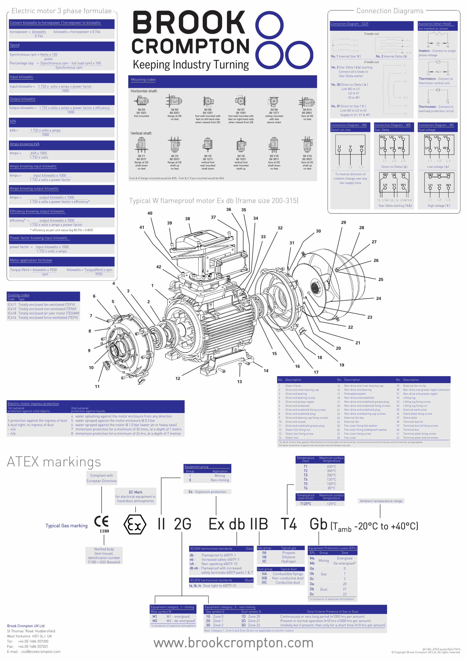
1234567891011121314
No. Description
Stator frameDrive end inner bearing capDrive end bearingDrive end bearing circlipDrive end grease nippleDrive end endshieldDrive end endshield fixing screwsDrive end endshield plugDrive end bearing cap fixing screwsDrive end oilsealDrive end endshield grease plugStator foot fixing nutStator foot fixing screwStator foot
* Ex db eb motors have gaskets fitted between terminal plate and terminal box, terminal box lid and terminal box and terminal box and glandplate.The above illustration is typical only and actual machine design may vary
1516171819202122232425262728
No. Description
Non-drive end inner bearing capNon-drive end bearingPreloaded washerNon-drive end endshieldNon-drive end endshield grease plugNon-drive end endshield fixing screwsNon-drive end endshield plugNon-drive end bearing cap screwsExternal fan keyExternal fanFan cover fixing flat washerFan cover fixing shakeproof washerFan cover fixing screwFan cover
2930313233343536373839404142
No. Description
External fan circlipNon-drive end grease nipple extensionNon-drive end grease nippleLifting lugLifting lug fixing screwLifting lug fixing nutExternal earth studGland plate fixing screwGland plateTerminal box lidTerminal box lid fixing screwTerminal boxTerminal plate fixing screwTerminal plate and terminals
Motor application formulae
Kilowatts = Torque(Nm) x rpm9550
Torque (Nm) = kilowatts x 9550rpm
Speed
Synchronous rpm = Hertz x 120poles
Percentage slip = (Synchronous rpm - full load rpm) x 100Synchronous rpm
Amps knowing input kilowatts
Amps = input kilowatts x 10001.732 x volts x power factor
Amps knowing output kilowatts
Amps = output kilowatts x 10001.732 x volts x power factor x efficiency*
Amps knowing kVA
Amps = kVA x 10001.732 x volts
kVA
kVA = 1.732 x volts x amps1000
Input kilowatts
Input kilowatts = 1.732 x volts x amps x power factor1000
Output kilowatts
Output kilowatts = 1.732 x volts x amps x power factor x efficiency1000
Efficiency knowing output kilowatts
efficiency* = output kilowatts x 10001.732 x volts x amps x power factor
Power factor knowing input kilowatts
power factor = input kilowatts x 10001.732 x volts x amps
Convert kilowatts to horsepower / horsepower to kilowatts
horsepower = kilowatts kilowatts = horsepower x 0.7460.746
Electric motor 3 phase formulae
Typical W flameproof motor Ex db (frame size 200-315)
Cooling codesCode
IC411IC410IC418IC416
Totally enclosed fan ventilated (TEFV)Totally enclosed non ventilated (TENV)Totally enclosed air over motor (TEOAM)Totally enclosed force ventilated (TEFV)
Type
Horizontal shaft:Horizontal shaft:
Vertical shaft:Vertical shaft:
IM B3IM B3IM 1001IM 1001
foot mounted
IM B5IM B5IM 3001IM 3001
flange at DEno feet
IM B14IM B14IM 3601 IM 3601 face at DE
no feet
IM B6IM B6IM 1051IM 1051
foot wall mounted withfeet on left-hand sidewhen viewed from DE
IM B7IM B7IM 1061IM 1061
foot wall mounted withfeet on right-hand sidewhen viewed from DE
IM B8IM B8IM 1071IM 1071
ceiling mountedwith feet
above motor
IM V1IM V1IM 3011IM 3011
flange at DEshaft down
no feet
IM V3IM V3IM 3031IM 3031
flange at DEshaft upno feet
IM V5IM V5IM 1011IM 1011
vertical footwall mountedshaft down
IM V6IM V6IM 1031IM 1031
vertical footwall mounted
shaft up
IM V18IM V18IM 3611IM 3611
face at DEshaft down
no feet
IM V19IM V19IM 3631IM 3631
face at DEshaft upno feet
Mounting codes
Foot & D flange mounted would be B35. Foot & C Face mounted would be B34
BBrrooookk CCrroommppttoonn UUKK LLttddSt Thomas’ Road HuddersfieldWest Yorkshire HD1 3LJ UKTel: +44 (0) 1484 557200Fax: +44 (0) 1484 557201E-mail: [email protected]
dh1304_ATEX poster/fp/c/10/16 © Copyright Brook Crompton UK Ltd. All rights reserved.
* efficiency as per unit value (eg 80.5% = 0.805)
U V W
Dust group
IIIIIIAAIIIIIIBBIIIIIICC
Combustible flyingsNon-conductive dustConductive dust
Typical dust
125°C
Maximum surfacetemperature
Temperatureclass (Dust)
TT112255°°CC