Advantage Flush System (AFS) - aecgroup.net Flush System (AFS) OPERATION MANUAL ... Advantage Flush...
27
Advantage Flush System (AFS) OPERATION MANUAL AEC GROUP INC. 17308 Mt. Wynne Circle Fountain Valley, CA 92708 Ph: (877) 906-1395 (714) 444-1395 Fax: (714) 444-1396 www.aecgroup.net ATTENTION: Read All Operating Instructions Before Use. Accreditations Pending
Transcript of Advantage Flush System (AFS) - aecgroup.net Flush System (AFS) OPERATION MANUAL ... Advantage Flush...

Advantage Flush System (AFS)OPERATION MANUAL
AEC GROUP INC.17308 Mt. Wynne Circle
Fountain Valley, CA 92708Ph: (877) 906-1395
(714) 444-1395 Fax: (714) 444-1396www.aecgroup.net
ATTENTION:Read All Operating
Instructions Before Use.
AccreditationsPending


TABLE OF CONTENTS
1
Warnings ..............................................................................................................................................2
Specifications .......................................................................................................................................3
Getting Started .....................................................................................................................................4
Unpacking Instructions......................................................................................................................4-5
Preparing Machine for Operation .....................................................................................................6-7
Programming Clock and Heater Time Clock......................................................................................8-9
Understanding the Keyboard..............................................................................................................10
Filling the Machine for the First Time................................................................................................11
Preparing to Perform a Flush Service.................................................................................................12
Performing an Engine Flush Service .............................................................................................13-15
How to Change the Solution.........................................................................................................16-17
Shutting Off the Machine...................................................................................................................18
Engines Not Recommended ...............................................................................................................18
Adapters ........................................................................................................................................19-20
Troubleshooting Guide ..................................................................................................................21-22
Avoiding Engine Overfills ...................................................................................................................23
Maintaining the Advantage Flush System.........................................................................................24
2
WARNINGSElectric Shock Can CauseInjury Or DeathInstall and maintain equipment in accordance withthe National Electrical Code (NFPA 70) and LocalCodes. Do not service or repair equipment withthe power on. Do not operate equipment withprotective insulators or covers removed. Serviceand repair to the equipment must be done by qualified and/or trained personnel only.
GroundingAll Advantage Flush Systems are equipped withgrounded power cords and plugs. Properly grounded receptacles are required, and in someinstances, a grounded plug adapter may berequired to comply with your State and LocalElectrical Codes.
Unplug power cord from the electrical outletbefore working on the equipment. Do not touch electrical hot parts.
Health Effects And First AidReferenceSafety glasses and protective clothing are recommended when handling the Advantage Flush Solution. Reference M.S.D.S., Section VII.
Acute Exposure:• SKIN CONTACT:
Remove contaminated clothing and shoes immediately; wash affected area with soap or mild detergent and large amounts of water. Reference M.S.D.S., Section VI.
• EYE CONTACT:Wash eyes immediately with large amounts of water or normal saline. Reference M.S.D.S., Section VI.
• INHALATION: Remove yourself from the exposed area to freshair immediately. Reference M.S.D.S., Section VI.
• INGESTION:Get medical attention immediately. Reference M.S.D.S., Section VI.
Advantage Flush SolutionStorage And DisposalObserve all Federal, State, and Local Regulationswhen storing and disposing of this substance. Forassistance contact the District Director of theEnvironmental Protection Agency. ReferenceM.S.D.S., Section VII.
• SMALL SPILLS:Take up with sand or other absorbent materials and place into containers for later disposal in accordance with Federal, State, and Local Regulations. Reference M.S.D.S., Section VII.
• WARNING:Advantage Flush Solution is oil based and very slippery.
!
3
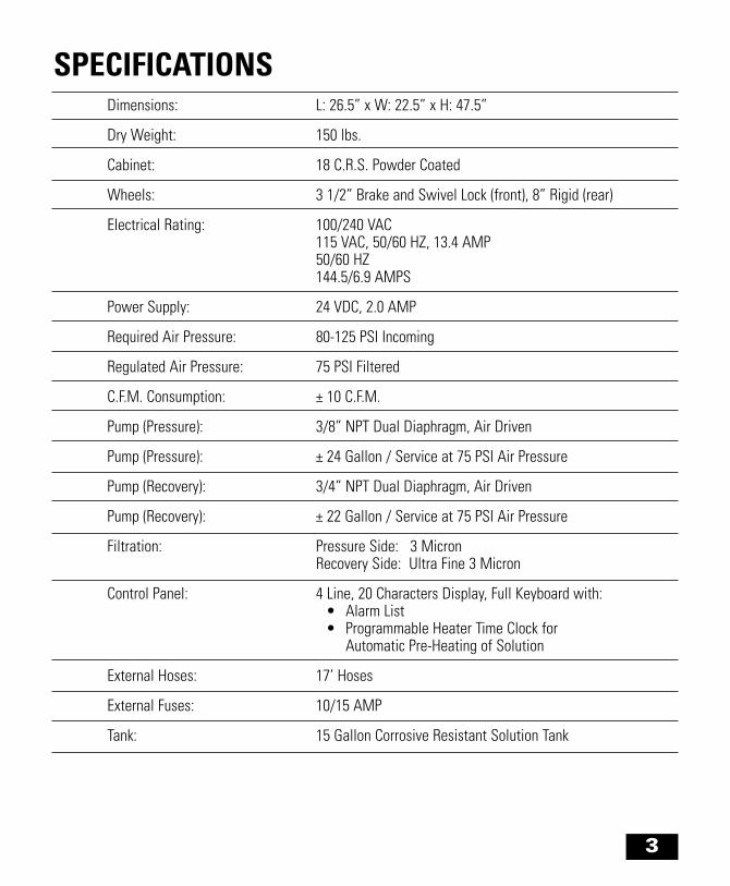
Dimensions: L: 26.5” x W: 22.5” x H: 47.5”
Dry Weight: 150 lbs.
Cabinet: 18 C.R.S. Powder Coated
Wheels: 3 1/2” Brake and Swivel Lock (front), 8” Rigid (rear)
Electrical Rating: 100/240 VAC115 VAC, 50/60 HZ, 13.4 AMP50/60 HZ144.5/6.9 AMPS
Power Supply: 24 VDC, 2.0 AMP
Required Air Pressure: 80-125 PSI Incoming
Regulated Air Pressure: 75 PSI Filtered
C.F.M. Consumption: ± 10 C.F.M.
Pump (Pressure): 3/8” NPT Dual Diaphragm, Air Driven
Pump (Pressure): ± 24 Gallon / Service at 75 PSI Air Pressure
Pump (Recovery): 3/4” NPT Dual Diaphragm, Air Driven
Pump (Recovery): ± 22 Gallon / Service at 75 PSI Air Pressure
Filtration: Pressure Side: 3 MicronRecovery Side: Ultra Fine 3 Micron
Control Panel: 4 Line, 20 Characters Display, Full Keyboard with:• Alarm List• Programmable Heater Time Clock for
Automatic Pre-Heating of Solution
External Hoses: 17’ Hoses
External Fuses: 10/15 AMP
Tank: 15 Gallon Corrosive Resistant Solution Tank
SPECIFICATIONS

4
AIR FITTING: Must have 1/4 NPTM threads.
AIR SUPPLY:80 PSI/5.6 BAR minimum at 10 CFM / 0.28 M3 min.
Shop Requirements:100-240 VAC APPLICATION:Requires 100-240 VAC, 14.5/6.9 AMPS rated grounded outlet.
WARNING: Machine draws up to 14.5 AMP; therefore, do not overload circuit.
!
!
WARNING: Pressure must not exceed 125 PSI / 8.6 BAR.
NOTE: Should you require any assistancecontact your local distributor.
GETTING STARTED
Unpack and assemble your system immediately. Remove the Advantage Flush System from its shippingcontainer. Look for any visible damage and report the damage to the freight carrier and your local distribu-tor. It is recommended that photographs be used to support all damage claims. All damage claims mustbe submitted to your local distributor in writing.When finished with unpacking and assembling the Advantage Flush System, complete and return theenclosed Limited Warranty Registration Card.
The following are included with your Advantage Flush System:• A Standard Adapter Kit.• Operation Manual.• Limited Warranty Registration Card.
Other items required:Advantage Flush Solution / Filter Pack.Containing the following:• One (1) box with forty (40) ultra fine 3 Micron filter elements and • One (1) 3 micron spin-on filter, and• Two (2) six (6) gallon containers of Advantage Flush Solution.
UNPACKING INSTRUCTIONS
5
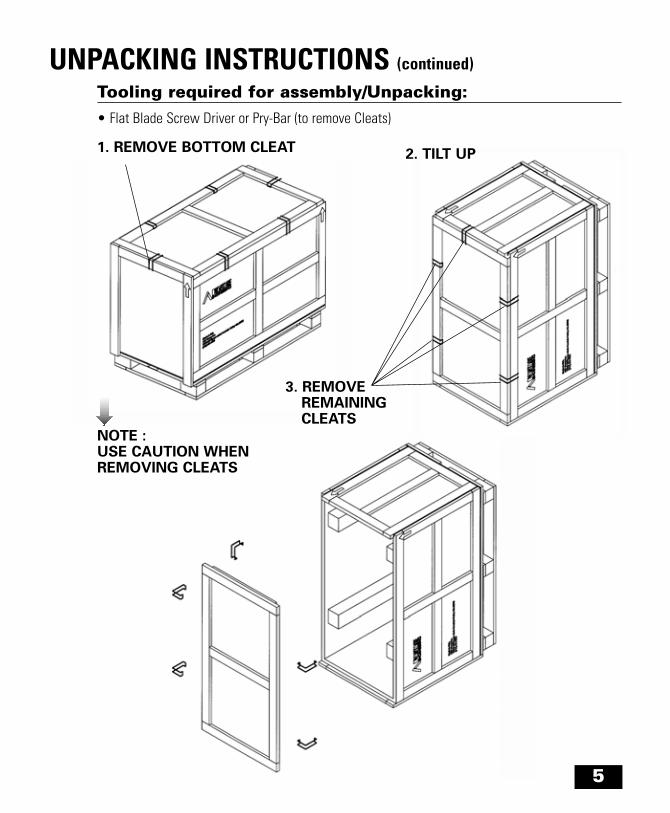
UNPACKING INSTRUCTIONS (continued)
NOTE : USE CAUTION WHENREMOVING CLEATS
2. TILT UP
3. REMOVEREMAINING CLEATS
1. REMOVE BOTTOM CLEAT
Tooling required for assembly/Unpacking:• Flat Blade Screw Driver or Pry-Bar (to remove Cleats)
6
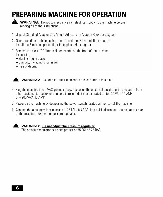
PREPARING MACHINE FOR OPERATION
1. Unpack Standard Adapter Set. Mount Adapters on Adapter Rack per diagram.
2. Open back door of the machine. Locate and remove red oil filter adapter. Install the 3-micron spin-on filter in its place. Hand tighten.
3. Remove the clear 10” filter canister located on the front of the machine.Inspect for:• Black o-ring in place.• Damage, including small nicks.• Free of debris.
WARNING: Do not connect any air or electrical supply to the machine before reading all of the instructions.
!
WARNING: Do not put a filter element in this canister at this time.!
WARNING: Do not adjust the pressure regulator.The pressure regulator has been pre-set at 75 PSI / 5.25 BAR.
!
4. Plug the machine into a VAC grounded power source. The electrical circuit must be separate from other equipment. If an extension cord is required, it must be rated up to 120 VAC, 15 AMP or + 200 VAC, 10 AMP.
5. Power up the machine by depressing the power switch located at the rear of the machine.
6. Connect the air supply (Not to exceed 125 PSI / 8.6 BAR) into quick disconnect, located at the rear of the machine, next to the pressure regulator.

7
PREPARING MACHINE FOR OPERATION (continued)
1. Program Reset: Used to reboot system upon program lockout. (See “Troubleshooting Guide”, “Flush cycle not working II”, Page 22
2. Password Cycle: To be used by Factory Representative only.
3. Date/Time: Used to set Date and Time. (See Pages 8-9.)
4. Heater Time Set: Used to set the Heater Time Clock. (See Pages 8-9.)
5. PLC/MTA Ver: Displays Software set up and Version
6. Password Tech: To be used by Factory Representative only.
NOTE:If this “Main Menu” is not shown, unplug the machine, wait ten (10) seconds, check the power source, and then re-plug the machine into the power source. If you still have no display, call your local distributor.
The “Main Menu” also includes the following function items:
Check the display on the front of the machine.The display panel will show the top portion of the “Main Menu” as seen below:
TTL SERVICES = 0
MAINT IN 588 FLUSHES
PACK SERVICES = 0
TANK TEMP = LOW
8
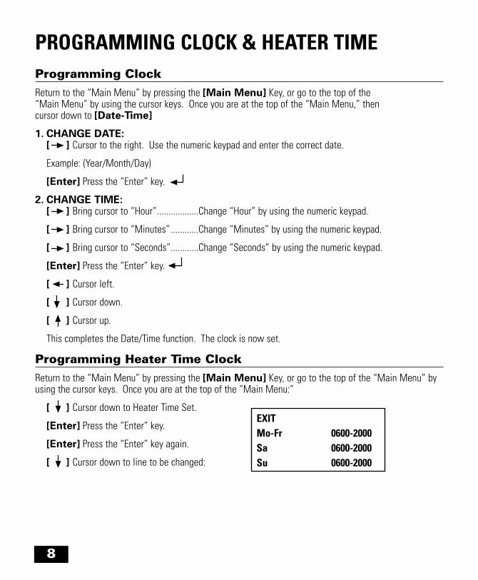
PROGRAMMING CLOCK & HEATER TIMEProgramming ClockReturn to the “Main Menu” by pressing the [Main Menu] Key, or go to the top of the “Main Menu” by using the cursor keys. Once you are at the top of the “Main Menu,” then cursor down to [Date-Time]
1. CHANGE DATE:[ ] Cursor to the right. Use the numeric keypad and enter the correct date.
Example: (Year/Month/Day)
[Enter] Press the “Enter” key.
2. CHANGE TIME:[ ] Bring cursor to “Hour”..................Change “Hour” by using the numeric keypad.
[ ] Bring cursor to “Minutes” ............Change “Minutes” by using the numeric keypad.
[ ] Bring cursor to “Seconds”............Change “Seconds” by using the numeric keypad.
[Enter] Press the “Enter” key.
[ ] Cursor left.
[ ] Cursor down.
[ ] Cursor up.
This completes the Date/Time function. The clock is now set.
Programming Heater Time ClockReturn to the “Main Menu” by pressing the [Main Menu] Key, or go to the top of the “Main Menu” byusing the cursor keys. Once you are at the top of the “Main Menu:”
[ ] Cursor down to Heater Time Set.
[Enter] Press the “Enter” key.
[Enter] Press the “Enter” key again.
[ ] Cursor down to line to be changed:
EXITMo-Fr 0600-2000Sa 0600-2000Su 0600-2000

DAY OF THE WEEK TIMEFrom-To From-ToMo - Fri 0600-1600
EXIT - +
ABORT FILLPAUSE
[ ] Cursor to Time Object. Cursor will appear on 0600.
To change value on First Time Object use “+” [Fill] Key or “-” [Abort] Key
[ ] Cursor to jump to next Time Object. Cursor will appear on 0600.
To change value on First Time Object use “+” [Fill] or “-” [Abort] Key
Repeat above instruction until all Time Objects are set to the required values.
Press “Exit” [Pause] Key
Press “Exit” [Pause] Key to return to “Main Menu”
Programming Heater Time Clock (continued)Set heater time +/- 20 minutes before opening and to the exact closing time.
In colder climates, set the time up to 60 minutes before opening.
On the days when the shop is closed, match on and off times (i.e. If the service department is closed on Sunday, program the time 0600-0600).
PROGRAMMING CLOCK & HEATER TIME (continued)
9
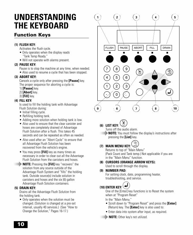
UNDERSTANDINGTHE KEYBOARD
1
9 6 7 8 10
2 3 4 5
FLUSH PAUSE ABORT FILL DRAIN
7 8 9
654
321
.0-
LIST MAIN
(1) FLUSH KEY:Activates the flush cycle.• Only operates when the display reads
“Tank Temp Ready.”• Will not operate with alarms present.
(2) PAUSE KEY:Pause is to stop the machine at any time, when needed.• Also used to resume a cycle that has been stopped.
(3) ABORT KEY:Cancels a cycle only after pressing the [Pause] key.The proper sequence for aborting a cycle is:1) [Pause] key.2) [Abort] key.3) [Fill] key.
(4) FILL KEY:Is used to fill the holding tank with Advantage Flush Solution during:• Initial filling cycle.• Refilling holding tank.• Adding more solution when holding tank is low.• Also used to ensure that the clear canister and
hoses are completely drained of Advantage Flush Solution after a flush. This takes 45 seconds and can be repeated as often as needed.
• Also used after an “Abort Cycle” to ensure that all Advantage Flush Solution has been recovered from the vehicle’s engine.
• You may press [Fill] key as many times asnecessary in order to clear out all the AdvantageFlush Solution from the canisters and hoses.NOTE: Pressing the [Fill] key “recovers” the solution from any source outside of the Advantage Flush System and “fills” the holding tank. Outside source(s) include solution in canisters and hoses and the six (6) gallon Advantage Flush Solution containers.
(5) DRAIN KEY:Drains all the Advantage Flush Solution from the holding tank.• Only operates when the solution must be
changed. (Solution is changed at a pre-set interval, usually 40 services.) (See “How to Change the Solution,” Pages 16-17.)
Function Keys
(6) LIST KEY:Turns off the audio alarm.
NOTE: You must follow the display’s instructions after pressing the [List] key.
(7) MAIN MENU KEY:Returns to top of “Main Menu” (Pack Count and Tank temp.) Not applicable if you are in the “Main Menu” function.
(8) CURSORS (ORANGE ARROW KEYS):Used to scroll through the display.
(9) NUMBER PAD:For setting clock, date, programming heater, troubleshooting, and service.
(10) ENTER KEY:One of the [Enter] key functions is to Reset the system when at “Program Reset”In the “Main Menu.”• Scroll down to “Program Reset” and press the [Enter]
(Return) key. The [Enter] key is also used to:• Enter data into system after input, as required.
NOTE: Other key’s not utilized.
10

11
FILLING THE MACHINE FOR THE FIRST TIME1. Unpack the two (2) six (6) gallon containers of Advantage Flush Solution.2. Uncoil black hose from hose hanger.3. Connect the 20” long black fill tube to the black hose. (Fill tube is located in upper adapter box.)
NOTE: Listen for audible click to ensure proper connection.4. Remove caps from all containers of Advantage Flush Solution. Place the fill tube into one of the
full containers of Advantage Flush Solution until the fill tube hits the bottom of the container.5. Press [Fill] key. The machine will automatically pump the Advantage Flush Solution into the
holding tank. Pump makes a normal pulsating sound.The display will show:
FILL CYCLE 0PAUSE
6. When the first container is empty, transfer the fill tube to the next container of Advantage Flush Solution. Repeat until two (2) containers are empty.
NOTE: The fill cycle will automatically stop the once the required level of Advantage Flush Solution is in the holding tank. Do not interrupt this process.
The display will show:
NOTE: If needed, press [Fill] key to completely remove any Advantage Flush Solution from clear canister and hoses.
9. Remove fill tube and return to upper adapter box.
10. Dispose of empty container according to Federal, State, and Local Regulations.
7. Press the [Main Menu] key.
The display will show:
FILLING COMPLETEPRESS MAIN KEY TO CONTINUE
TTL SERVICES = 0MAINT IN 588 FLUSHESPACK SERVICES = 0TANK TEMP = LOW
12
PREPARING TO PERFORM A FLUSH SERVICE1. Allow the Advantage Flush Solution to automatically heat to ± 105° F. The machine will heat up
the solution automatically as long as the current time is within your time clock setting.
NOTE: When operating temperature is reached the display will show “Tank Temp Ready.” The machine takes 15-40 minutes to heat the Advantage Flush Solution, depending on ambient temperature.
2. Install new ultra fine filter into the 10” clear canister, located on the front of the machine.
NOTE: Check the canister and black o-ring for any nicks and/or debris. Clean or replace if necessary.
* Dependent on software, solution change may be different (i.e. 20 or 30).
WARNING: After completion of 40 flushes* you must change the solution. If the machine isattached (hooked-up) to a vehicle and the [Drain] key is pressed, all of the solution will be pumpedinto the vehicle’s engine, causing a severe overfill condition. Never press the [Drain] key when thesystem is attached to an engine. (See “How to Change the Solution,” pages 9-1 through 9-2).
!

PERFORMING AN FLUSH SERVICE1. Drain oil and remove oil filter from the engine.
2. Select proper oil filter adapter from adapter rack. (See “Engines Not Recommended”, Page 18 and “Adapters”, Pages 19-20 for additional information and diagrams.)
13
NOTE: Use a solvent when cleaning adapters.
3. Attach oil filter port adapter to oil port by selecting the correct insert and lock it into the orifice on the adapter base; determine o-ring diameter, use larger diameter adapter plate if necessary, then attach to oil filter port. (See “Adapters”, Pages 19-20 for additional information.)
4. Select Oil Pan Adapter:Use appropriate oil pan drain plug adapter. Thread it into the pan. Hand tight is sufficient. Attach the 90° adapter assembly to the drain pan plug turning until hand tight.
5. Lock wheel brakes, located on the front of the machine.
NOTE: Check to ensure brakes are secure.
7. Connect the red hose to the oil filter adapter and the black hose to the oil pan adapter.
NOTE: Listen to audible click to ensure proper connection.
WARNING: Adapters and mating engine oil filter port surface must be clean.Engine damage may occur by failing to clean these surfaces.
!
WARNING: To avoid engine overfill make sure the hoses are properly aligned and connected to ensure there are no twists or kinks of adapter hoses and red and/or black external hoses.
!
8. Press [Flush] key.
9. Check for leaks in all attachments.
• If leaking air or fluid press the [Pause] key and eliminate the leaks.
• Press the [Pause] key to continue the flush.

PERFORMING AN FLUSH SERVICE (continued)
14
WARNING: After pressing the [Flush] key, it should take approximately 30 seconds forsolution to start returning from the engine to the Advantage Flush System. If no solution isflowing back to the Advantage Flush System, press the [Pause] key and check to ensurethat all connections are secure before continuing the service.
Once the problem has been corrected, press the [Pause] key to continue the flush. If after an additional 20 to 30 seconds the solution is still not flowing back to the Advantage Flush System, press the [Pause] key immediately. Correct the problem before any further attempt is made to perform the service. (See table on “Avoiding Engine Overfill,” page 21.)
!
10. The Advantage Flush System performs the service in four (4) stages.• The first three stages consist of a 100 second flush and up to a 90 second recovery.• The fourth stage consists of a 100 second flush and up to a 180 second recovery.
STAGE I 100 seconds up to 90 seconds
STAGE II 100 seconds up to 90 seconds
STAGE III 100 seconds up to 90 seconds
STAGE IV 100 seconds up to 180 seconds
Flush Recovery
Flush Cycle: Heated and pressurized (± 42 PSI), solution is pumped with pulsating action through the oil filter port to the main bearings, rod bearings, oil galleys, camshaft bearings, and valve lifters. Solution flows to the oil pan and is vacuum extracted through the drain plug adapter to the Advantage Flush System. The Advantage Flush System filters the contaminated solution through ultra fine 3 micron filters.
Recovery Cycle: Vacuum extracts all of the solution from the engine and pumps it back to the holding tank.
Final Recovery Cycle: During the first 105 seconds of “Last” recovery the air is pumped through the oil filter port adapter to force excess fluid and sludge debris from the engine to the oil pan, where it is evacuated. You may notice that the pump sounds as if it is picking up speed. When the service is completed the buzzer will sound five (5) times and the display will show that the service is completed.Check the clear filter canister to make sure that it is empty of solution. If not press [Fill] key, which will cause the system to run a 45 second recovery cycle.
NOTE: You can press the [Fill] key as often as required to recover all of the Advantage Engine Flush Solution in the 10” clear canister.

15
PERFORMING AN FLUSH SERVICE (continued)
11. Detach the red and black hose from the engine and rehang them.
NOTE: Avoid dropping and or dragging the hose ends on the floor. If the hose ends become dirty, clean with solvents.
12. Remove adapters from the engine.
13. Clean adapters with a clean rag or towel.
14. Return adapters to adapter rack.
15. Complete the oil change process.
16. Remove the ultra fine filter from the clear canister. Properly dispose of the used filter according to Federal, State, and Local Regulations.
The Advantage Flush System is now ready for the next service. (Refer back to Page 12.)
16
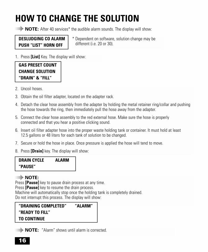
HOW TO CHANGE THE SOLUTIONNOTE: After 40 services* the audible alarm sounds. The display will show:
2. Uncoil hoses.
3. Obtain the oil filter adapter, located on the adapter rack.
4. Detach the clear hose assembly from the adapter by holding the metal retainer ring/collar and pushing the hose towards the ring, then immediately pull the hose away from the adapter.
5. Connect the clear hose assembly to the red external hose. Make sure the hose is properly connected and that you hear a positive clicking sound.
6. Insert oil filter adapter hose into the proper waste holding tank or container. It must hold at least 12.5 gallons or 48 liters for each tank of solution to be changed.
7. Secure or hold the hose in place. Once pressure is applied the hose will tend to move.
8. Press [Drain] key. The display will show:
1. Press [List] Key. The display will show:
NOTE: Press [Pause] key to pause drain process at any time. Press [Pause] key to resume the drain process. Machine will automatically stop once the holding tank is completely drained.Do not interrupt this process. The display will show:
NOTE: “Alarm” shows until alarm is corrected.
DESLUDGING CO ALARMPUSH “LIST” HORN OFF
GAS PRESET COUNT CHANGE SOLUTION“DRAIN” & “FILL”
DRAIN CYCLE ALARM“PAUSE”
“DRAINING COMPLETED” “ALARM”“READY TO FILL”TO CONTINUE
* Dependent on software, solution change may be different (i.e. 20 or 30).
17
HOW TO CHANGE THE SOLUTION (continued)
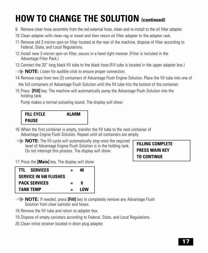
9. Remove clear hose assembly from the red external hose, clean and re-install to the oil filter adapter.10. Clean adapter with clean rag or towel and then return oil filter adapter to the adapter rack.11. Remove old 3 micron spin-on filter located at the rear of the machine, dispose of filter according to
Federal, State, and Local Regulations.12. Install new 3 micron spin-on filter, secure in a hand tight manner. (Filter is included in the
Advantage Filter Pack.)13. Connect the 20” long black fill tube to the black hose (Fill tube is located in the upper adapter box.)
NOTE: Listen for audible click to ensure proper connection.14. Remove caps from two (2) containers of Advantage Flush Engine Solution. Place the fill tube into one of
the full containers of Advantage Flush Solution until the fill tube hits the bottom of the container.15. Press [Fill] key. The machine will automatically pump the Advantage Flush Solution into the
holding tank.Pump makes a normal pulsating sound. The display will show:
16. When the first container is empty, transfer the fill tube to the next container of Advantage Engine Flush Solution. Repeat until all containers are empty.
NOTE: The fill cycle will automatically stop once the required level of Advantage Engine Flush Solution is in the holding tank. Do not interrupt this process. The display will show:
FILL CYCLE ALARMPAUSE
FILLING COMPLETEPRESS MAIN KEYTO CONTINUE
TTL SERVICES = 40 SERVICE IN 548 FLUSHESPACK SERVICES = 0 TANK TEMP = LOW
NOTE: If needed, press [Fill] key to completely remove any Advantage Flush Solution from clear canister and hoses.
18. Remove the fill tube and return to adapter box.19. Dispose of empty canisters according to Federal, State, and Local Regulations.20. Clean inline strainer located in drain plug adapter.
17. Press the [Main] key. The display will show:
18
SHUTTING OFF THE MACHINENOTE: Do not shut off the power source to the Advantage Flush System during any operating cycle.
The Advantage Flush System is equipped with an energy saver time clock and should not be disconnected from electrical power during non-business hours. Machines can be programmed to pre-heat the Advantage Flush Solution before opening for business and shut heaters off after hours (See “Programming Clock and Heater Time Clock,” Pages 8-9.)
NOTE: If you have any questions or require any assistance contact your local distributor.
ENGINES NOT RECOMMENDEDThe Advantage Flush Service is not recommended for the following engines:Horizontal or opposed engines such as:
•Porsche 911, 912, and 914
•Volkswagen Vanagon
•Chevrolet Corvair
•Subaru with pancake motors
All rotary engines such as:
•Mazda RX-7
All dry sump motors such as:
•Mercedes Benz 6.9 (1975-1979)
Worn Engines:
The purpose of engine flushing is to remove sludge and contaminant build-up from the engine’s internaloil system. It is not meant to be a corrective measure for needed mechanical repairs.

19
ADAPTERSThe Advantage Flush System, when attached to an engine, becomes a closed-loop, pressurized systemthat injects and extracts solution through the engine with a patented adapter system.
The Advantage Flush System is shipped with an adapter set that includes Oil Filter Port, or Upper Adapters for spin on filter applications and Oil Pan, or Lower Adapters.
Oil Filter Port AdaptersIn all cases it will be necessary to use the oil filter base adapter when connecting to the oil filter port ofthe engine. Depending on the engine’s oil filter housing, some combination of one or more of the otherupper adapters will be necessary to produce an effective attachment to the engine. In 90% of the cases when a spin-on filter is used, the outer housing lip of the oil filter housing and the center post are levelwith each other. Take one of the upper adapter inserts and lock into the oil filter base adapter. This assembly is directly attached to the engine’s oil filter housing (hand tighten).

20
ADAPTERS (continued)
If the outer lip of the engines oil filter housing is larger in diameter than the oil filter base plate, it will be necessary to add an adapter plate. (Illustrated below.)
If there is an extended center-post in the engine’s oil filter housing, it will be necessary to add the extension sleeve to the base plate and one of the internal extension sleeves.
Drain Pan AdaptersDrain PanTake the appropriate sized oil pan drain plug adapter (silver colored) and screw it into the oil pan drain opening. Attach the adapter assembly to the drain pan plug turning until hand tight.
Oil pan drain plug adapter
Insert
In-line strainer
Drain adapter assembly
Adapter plate
External sleeve
Internal sleeve

21
TROUBLESHOOTING GUIDEPROBLEM CAUSE(S) WHAT TO DO
No display No power. Check the wall receptacle for the proper voltage.
Machine not plugged in. Plug in.
On/Off switch is not Turn the On/Off switch, located on the back of the in the “On” position. machine, to the “On” position.
Fuse blown. Check the 5 AMP and 10-15 AMP Fuse, replace if blown.The fuses are located on the back of the machine abovethe On/Off Switch, lower fuse is 10-15 AMP, upper fuse is 5 AMP.
Loose wires / Check for security on all wires, if wire(s) are loose, bad connection UNPLUG MACHINE, tighten wire(s), and recheck.
Tank Low voltage from Check voltage in shop. If voltage is lower than 92% of thetemperature wall outlet normal required voltage, the unit will not heat properly.low
Amperage on extension cord Remove extension cord and replace with a cord that is not rated at 15 AMPS 15 AMP rated, or plug directly into the wall power outlet.
Machine 1) Disconnect air, press the [Fill] key, check for is low “Low Fill Cycle”. If counters run, let the counter in solution run until cycle has completed. Wait 20-60 minutes
for the machine to heat the solution.
2) If counter does not run, press the [Pause] key, thenpress the [Abort] key, then press the [Main Menu] key.Go to the program reset and press the [Enter] key.
3) Repeat Step 1 with air connected. If counters do not run, add one (1) six (6) gallon container of solution to the internal tank. Wait 20-60 minutes for the machine to heat solution.
Bad mechanical relay. Check for 24 VDC on purple and colored wires,located on mechanical relay(s). If 24 VDC is present, check for closed contact position. If contact is not closed, replace relay(s).
No fluid No air pressure. Check if shop air is connected to the unitcirculation and the pressure is set at 75-80 PSI.
Internal 3 Micron Filter Make sure 3 Micron Filter is installed and hand tightened.loose or not installed.
22
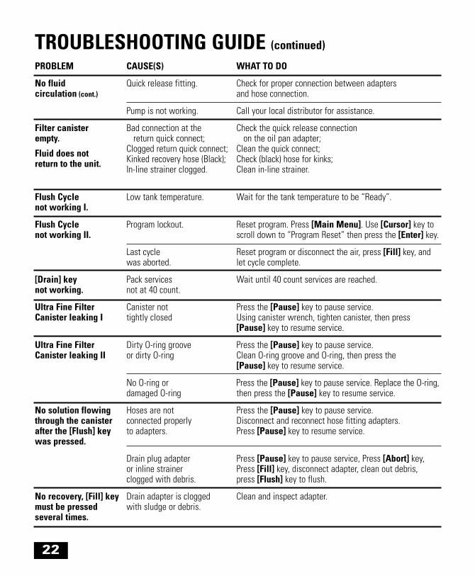
TROUBLESHOOTING GUIDE (continued)
PROBLEM CAUSE(S) WHAT TO DO
No fluid Quick release fitting. Check for proper connection between adapterscirculation (cont.) and hose connection.
Pump is not working. Call your local distributor for assistance.
Filter canister Bad connection at the Check the quick release connection empty. return quick connect; on the oil pan adapter;
Fluid does not Clogged return quick connect; Clean the quick connect;
return to the unit. Kinked recovery hose (Black); Check (black) hose for kinks;In-line strainer clogged. Clean in-line strainer.
Flush Cycle Low tank temperature. Wait for the tank temperature to be “Ready”.not working I.
Flush Cycle Program lockout. Reset program. Press [Main Menu]. Use [Cursor] key to not working II. scroll down to “Program Reset” then press the [Enter] key.
Last cycle Reset program or disconnect the air, press [Fill] key, andwas aborted. let cycle complete.
[Drain] key Pack services Wait until 40 count services are reached.not working. not at 40 count.
Ultra Fine Filter Canister not Press the [Pause] key to pause service. Canister leaking I tightly closed Using canister wrench, tighten canister, then press
[Pause] key to resume service.
Ultra Fine Filter Dirty O-ring groove Press the [Pause] key to pause service. Canister leaking II or dirty O-ring Clean O-ring groove and O-ring, then press the
[Pause] key to resume service.
No O-ring or Press the [Pause] key to pause service. Replace the O-ring,damaged O-ring then press the [Pause] key to resume service.
No solution flowing Hoses are not Press the [Pause] key to pause service. through the canister connected properly Disconnect and reconnect hose fitting adapters. after the [Flush] key to adapters. Press [Pause] key to resume service.was pressed.
Drain plug adapter Press [Pause] key to pause service, Press [Abort] key,or inline strainer Press [Fill] key, disconnect adapter, clean out debris,clogged with debris. press [Flush] key to flush.
No recovery, [Fill] key Drain adapter is clogged Clean and inspect adapter.must be pressed with sludge or debris.several times.
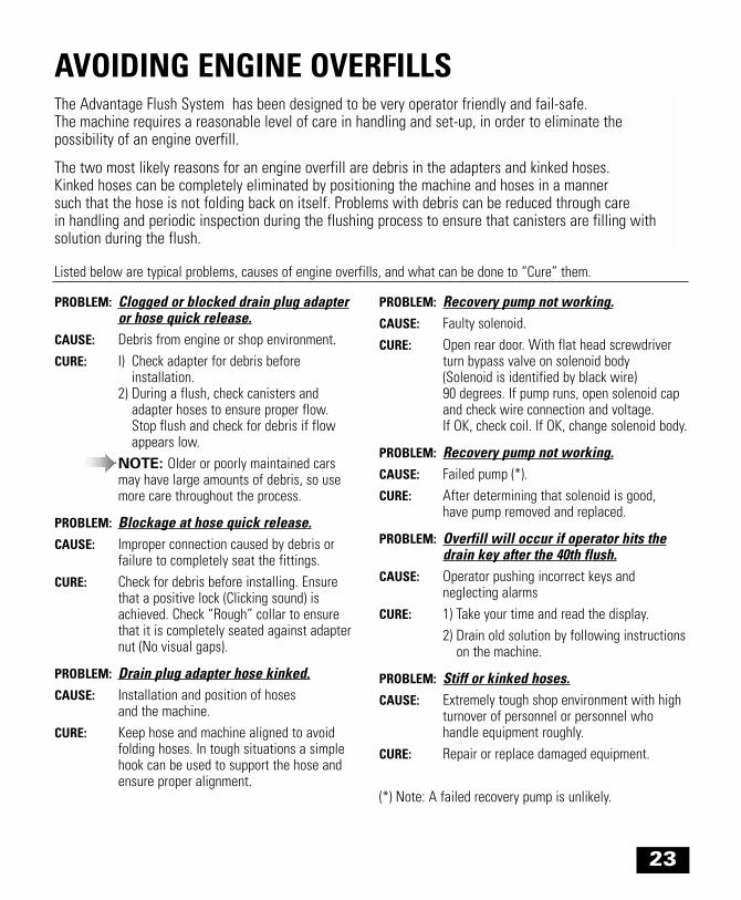
Listed below are typical problems, causes of engine overfills, and what can be done to “Cure” them.
The Advantage Flush System has been designed to be very operator friendly and fail-safe. The machine requires a reasonable level of care in handling and set-up, in order to eliminate the possibility of an engine overfill.
The two most likely reasons for an engine overfill are debris in the adapters and kinked hoses. Kinked hoses can be completely eliminated by positioning the machine and hoses in a manner such that the hose is not folding back on itself. Problems with debris can be reduced through care in handling and periodic inspection during the flushing process to ensure that canisters are filling withsolution during the flush.
23
AVOIDING ENGINE OVERFILLS
PROBLEM: Clogged or blocked drain plug adapteror hose quick release.
CAUSE: Debris from engine or shop environment.CURE: I) Check adapter for debris before
installation.2) During a flush, check canisters and
adapter hoses to ensure proper flow. Stop flush and check for debris if flow appears low.
NOTE: Older or poorly maintained carsmay have large amounts of debris, so use more care throughout the process.
PROBLEM: Blockage at hose quick release.CAUSE: Improper connection caused by debris or
failure to completely seat the fittings.CURE: Check for debris before installing. Ensure
that a positive lock (Clicking sound) is achieved. Check “Rough” collar to ensure that it is completely seated against adapternut (No visual gaps).
PROBLEM: Drain plug adapter hose kinked.CAUSE: Installation and position of hoses
and the machine.CURE: Keep hose and machine aligned to avoid
folding hoses. In tough situations a simple hook can be used to support the hose andensure proper alignment.
PROBLEM: Recovery pump not working.CAUSE: Faulty solenoid.CURE: Open rear door. With flat head screwdriver
turn bypass valve on solenoid body(Solenoid is identified by black wire) 90 degrees. If pump runs, open solenoid capand check wire connection and voltage. If OK, check coil. If OK, change solenoid body.
PROBLEM: Recovery pump not working.CAUSE: Failed pump (*).CURE: After determining that solenoid is good,
have pump removed and replaced.
PROBLEM: Overfill will occur if operator hits thedrain key after the 40th flush.
CAUSE: Operator pushing incorrect keys and neglecting alarms
CURE: 1) Take your time and read the display.2) Drain old solution by following instructions
on the machine.
PROBLEM: Stiff or kinked hoses.CAUSE: Extremely tough shop environment with high
turnover of personnel or personnel who handle equipment roughly.
CURE: Repair or replace damaged equipment.
(*) Note: A failed recovery pump is unlikely.
24
MAINTAINING THE ADVANTAGE FLUSH SYSTEM
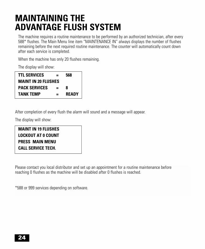
The machine requires a routine maintenance to be performed by an authorized technician, after every 588* flushes. The Main Menu line item “MAINTENANCE IN” always displays the number of flushes remaining before the next required routine maintenance. The counter will automatically count down after each service is completed.
When the machine has only 20 flushes remaining.
The display will show:
TTL SERVICES = 568MAINT IN 20 FLUSHESPACK SERVICES = 8TANK TEMP = READY
MAINT IN 19 FLUSHESLOCKOUT AT 0 COUNTPRESS MAIN MENU CALL SERVICE TECH.
Please contact you local distributor and set up an appointment for a routine maintenance before reaching 0 flushes as the machine will be disabled after 0 flushes is reached.
*588 or 999 services depending on software.
After completion of every flush the alarm will sound and a message will appear.
The display will show:

AEC GROUP INC.17308 Mt. Wynne Circle / Fountain Valley, CA 92708Ph: (877) 906-1395 / (714) 444-1395 / Fax: (714) 444-1396www.aecgroup.net
PN 7701-40-00-1