An Approach to Select the Optimum Rock Failure Criterion ...
A NEW STRENGTH TENSOR BASED FAILURE CRITERION FOR ANISOTROPIC MATERIALS
Paul V. Osswald, Technical University of Munich, Munich, Germany
Tim A. Osswald, Polymer Engineering Center, University of Wisconsin-Madison, WI
Abstract
A recently published 3D failure criterion [1] for anisotropic materials that incorporates stress interactions is presented. The strength tensor model includes fourth order strength tensor stress interaction components that can be computed based on the slope of the failure surface at distinct stress axes intersections, making the model apt to fit failure surfaces for a variety of anisotropic materials. Experimental data from the literature for unidirectional FRP’s, an anisotropic paperboard material and textile reinforced composites are used to validate the model.
Introduction
With rapidly growing use of continuous, chopped and textile fiber reinforced polymer composites in the design and manufacture of critical parts and structures for the aerospace and automotive industries, interest in the strength and failure of these parts has been continually growing. In the past decades, various failure criteria models have been developed and modified. Some models were developed for unidirectional fiber reinforced composites and cannot be extended to model failure in systems with fiber orientation distributions, nor textile reinforced composite structures. Furthermore, none of the existing models account for all modes of failure [2,3], nor include all stress interactions, if any. Some only include interactions between normal stresses, such as the interaction between longitudinal and transverse normal stresses and others only include interactions between the transverse shear stress and transverse normal stress. Today, there are two general families of failure criteria. The first and oldest one are strength tensor based criteria, which represent the failure surface with a single scalar function, such as the Tsai-Hill [4], the Gol’denblat-Kopnov [5], the Malmeister [6] or Tsai-Wu [7] and the Theocaris [8] criteria. In addition to the basic engineering failure strengths such as longitudinal and transverse strengths in tension and compression, as well as shear strengths, they include the interaction between longitudinal stress and transverse stress. Such models, such as the Tsai-Wu model, are widely used and have been incorporated into finite element analysis software to perform strength analysis of anisotropic parts. However, these models don’t include the interaction between normal stresses and shear stresses, which dominate the inter-fiber
failure mode in UD-FRP’s. The second family of models includes those that incorporate physical aspects of fracture, often termed phenomenological or mechanistic models, such as the ones by Sun [9], Puck [10], Pinho [11], Dávila [12] and Cuntze [13-15]. These models do not include the interaction between longitudinal stresses and transverse stresses, but concentrate on the interaction between transverse stresses and transverse shear stresses, modeling quite well the shear strength strengthening effect during transverse compression. This second family of failure criteria was explicitly developed to predict the failure of UD-FRP.
Figure 1: Types of FRP Composites This paper presents a strength tensor based failure
criterion, recently published by the authors [1], which includes fourth order tensor components that represent the interactions between stresses and can be applied to any anisotropic fiber reinforced composite material, such as continuous, chopped and woven fiber reinforced systems, subjected to complex stress fields, as schematically depicted in Figure 1. The new failure criterion is
SPE ANTEC® Anaheim 2017 / 741

compared to experimental data from the literature for unidirectional fiber reinforced composite laminates, a paperboard anisotropic material and a textile-reinforced composite.
Strength Tensor Based Failure Criterion
The failure criterion presented here [1] is a strength tensor model based on the Gol’denblat-Kopnov criterion [5]. The model presented by Gol’denblat and Kopnov defines a scalar failure function, f, as a function of strength tensors and stresses using 𝑓 = 𝐹%&𝜎%&
(+ 𝐹%&*+𝜎%&𝜎*+
,+ ⋯ (1)
were failure is expected when 𝑓 ≥ 1. The proposed strength tensor components 𝐹%& and 𝐹%&*+ are second and fourth order tensors, respectively, that depend on engineering strength parameters such as 𝑋1, 𝑋2, 𝑌1, 𝑌2, and 𝑆, which represent the maximum tensile and compressive stresses for the longitudinal (𝜎55) and transverse (𝜎66) directions and maximum shear strength (𝜏56), respectively. The tensors satisfy the symmetry conditions, 𝐹%& = 𝐹&% and 𝐹%&*+ = 𝐹*+%&. To achieve a linear criterion scalar function f, Gol’denblat and Kopnov set the exponents 𝛼 = 1 and 𝛽 = 1/2. Through this additive tensor technique Gol’denblat and Kopnov were able to couple all the failure modes into one single function, where a separate treatment of compressive and tensile modes is not required. For the plane stress case the Gol’denblat-Kopnov criterion becomes 𝑓 = 𝐹55𝜎55 + 𝐹66𝜎66 + 𝐹56𝜏56 + 𝐹5555𝜎556 +𝐹6666𝜎666 + 𝐹5656𝜏566 + 2𝐹5566𝜎55𝜎66 + 2𝐹5556𝜎55𝜏56 +2𝐹6656𝜎66𝜏56 5 6 (2) where the usual notation of 𝜎%% and 𝜏%&, for normal and shear stresses, respectively, was used. Gol’denblat and Kopnov dropped the stress interaction terms 𝐹5556 and 𝐹6656 terms and solved for most of the strength tensor components by assuming uniaxial conditions in the 1 and 2 directions or a shear condition in the 1 − 2 plane. In order to determine the 𝜎55−𝜎66 interaction strength tensor component 𝐹5566, Gol’denblat and Kopnov measured the positive and negative shear strengths, 𝑆=>? and 𝑆=>@, of a specimen where the fibers where oriented at 45°. The strength tensor terms given by Gol’denblat and Kopnov [5] are presented in Table 1. The model developed by the authors includes interaction terms 𝐹5556 and 𝐹6656 as well as the general strength tensor components, 𝐹%&*+. These interaction terms are based on the slopes of the failure surface (𝑓 = 1) at any of the points where the engineering strength values
are known within an arbitrary 𝜎%&−𝜎*+ plane. Hence, there is minimal experimental data needed to compute the slope of the failure surface around any of the four strength values within a 𝜎%&−𝜎*+ plane, hence, being able to calculate the interaction strength tensor component 𝐹%&*+. For this, the interaction terms between normal stresses and the interaction between normal and shear stresses are derived separately, as schematically depicted in Figure 2. Table 1. Strength tensor components
Tensor Component
From Gol’denblat-Kopnov [5]
𝐹55 12
1𝑋1−1𝑋2
𝐹5555 14
1𝑋1+1𝑋2
6
𝐹66 12
1𝑌1−1𝑌2
𝐹6666 14
1𝑌1+1𝑌2
6
𝐹56 0
𝐹5656 1𝑆6
𝐹5566
18
1𝑋1+1𝑋2
6
+1𝑌1+1𝑌2
6
−1𝑆=>?
+1𝑆=>@
6
To illustrate this we can take the 𝜎55−𝜎66 interaction, 𝐹5566, point on the failure surface where 𝜎55 = 𝜎55E1F = 𝑋1 and 𝜎66 = 0 and where the failure surface has a slope of HIJJ
HIKK= 𝜆55566. After taking the
derivative of equation (2) with respect to σ55, at the failure surface where 𝑓 = 1 and 𝜏56 = 0, the interaction term can easily be computed and is given by
𝐹5566 = − NKKKKKJ NKKONJJPKKKJJ ONKKKK
PKKKJJ (5)
𝐹5566 can also be evaluated at any of the remaining
three axes intersections of the failure surface within the 𝜎55−𝜎66 plane. Ideally, the same computed numerical value for the strength tensor interaction term will result from all four axes intersections. Table 2 presents the interaction strength tensor components for the more general case where the subscripts 1122 where replaced with iijj. To mathematically evaluate the interaction between normal stresses and shear stresses, such as 𝐹6656,
SPE ANTEC® Anaheim 2017 / 742

we assume symmetry by replacing 𝜏%& with 𝜏%& and propose an interaction term 𝐹%%%& based on the slope of the
failure surface, HSTUHITT
= 𝜇%%%&, at 𝜏%& = 𝜏%&F = 𝑆 and 𝜎%% = 0, as schematically depicted in Figure 2. This strength tensor component is also presented in general form in Table 2. The reader should consult reference [1] for the Malmeister or Tsai-Wu models’ interaction strength tensor components derived using the above technique.
Figure 2: Locations on the failure surface within the
𝜎%%−𝜎&& (a) and 𝜎%%−𝜏%& (b) planes where the interaction 𝐹%%&& and 𝐹%%%&, respectively, are evaluated
Comparison with Experimental Data
The present model was tested by comparing it to
other models and experimental data for unidirectional FRP materials, as well as experimental data for an
anisotropic paperboard and a two-ply plain weave CFRP laminate.
Table 2. Interaction strength tensor components (𝜏56F = 𝑆, etc.).
Tensor
Component
Present model
𝐹%%%& −𝐹%%𝜏%&F
− 𝐹%&%&𝜇%%%&
𝐹%%&&(𝜆5%%&&)
−𝐹%% + 𝐹&&𝜆5
%%&& 𝐹%%%%5/6 + 𝐹%%%%𝜆5%%&&
𝐹%%&&(𝜆6%%&&) − 𝐹%% + 𝐹&&𝜆6
%%&& 𝐹&&&&5/6 − 𝐹&&&&𝜆6%%&&
𝐹%%&&(𝜆Y%%&&) 𝐹%% + 𝐹&&𝜆Y
%%&& 𝐹%%%%5/6 − 𝐹%%%%𝜆Y%%&&
𝐹%%&&(𝜆=%%&&) 𝐹%% + 𝐹&&𝜆=
%%&& 𝐹&&&&5/6 − 𝐹&&&&𝜆=%%&&
Unidirectional FRP
The failure of unidirectional composites in the 𝜎55−𝜎66, 𝜏56−𝜎66 and 𝜏56−𝜎55 stress planes was analyzed with the present model, and compared to experiments performed with glass and carbon reinforced epoxy composites. The data was taken from the first World Wide Failure Exercise (WWFE-I) [16]. The WWFE-I fiber failure data for the σ55−σ66 plane presented in Figure 3 was modeled using the present model using a 𝜆=5556=0.041.
Figure 3: Comparing the present model using 𝜆=5556=0.041
to WWFE-I experimental data
The second test of the model was done with the inter-fiber failure WWFE-I data 𝜏56−𝜎66 stress plane used in Figures 4. The best fit of the experimental data resulted with a parameter 𝜇6656=-0.77. The present model is also compared to the Gol’denblat-Kopnov [5] and the Cuntze
SPE ANTEC® Anaheim 2017 / 743
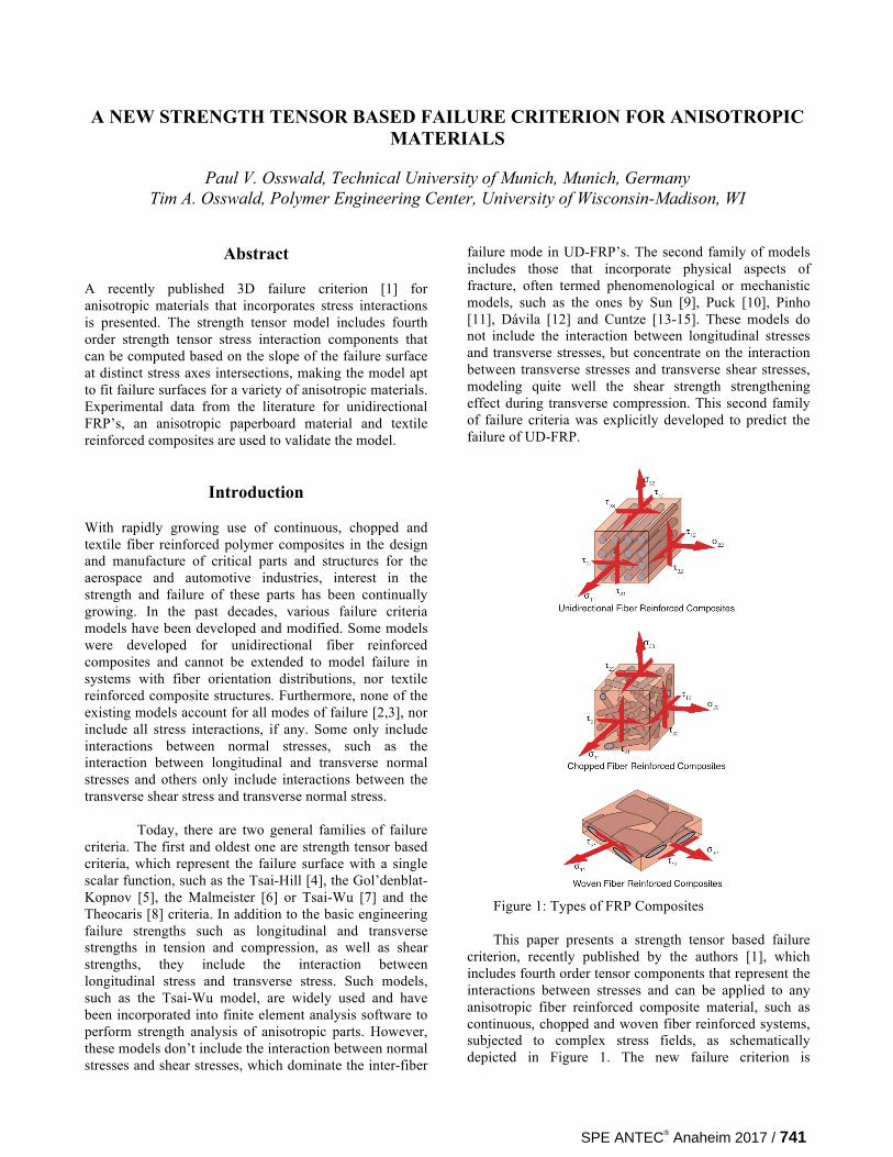
[13] criteria. For the Cuntze criterion 𝜇6656E1 = 𝜇6656E2=-0.55 was used. The Cuntze “friction” parameter can be adjusted independently in tension and compression to fit the data accordingly. However, the Cuntze model misses the data points on the left of the curve. Here, the experimental data exhibits a compressive transverse strength increase that is also reflected by the present model. It is not quite clear if the compressive transverse strength increase is real. While the authors have observed this “bulge” in other experimental data [13], the literature remains silent on this issue.
Figure 4: Comparing the present model using 𝜇6655=-0.77 to a biaxial failure stress envelope under transverse stress and shear stress loading data from the WWFE-I [16] and to the Cuntze model
The last set of experimental data used to test the
present model with unidirectional FRPC materials, is the longitudinal stress under shear stress in the 𝜏56−𝜎55 stress plane also used in Figure 5. Using the present model with a parameter 𝜇5556=0.054, the shear strengthening effect under tensile longitudinal loads is clearly observed in the figure.
Figure 5: Comparing the present model to WWFEI biaxial failure stress envelope data under longitudinal and shear stress loading results [16], using 𝜇5556=0.054
Anisotropic Paperboard To test the present model with an anisotropic material with a fiber orientation distribution, experiments performed on paperboard by Suhling et al. [17] were used.
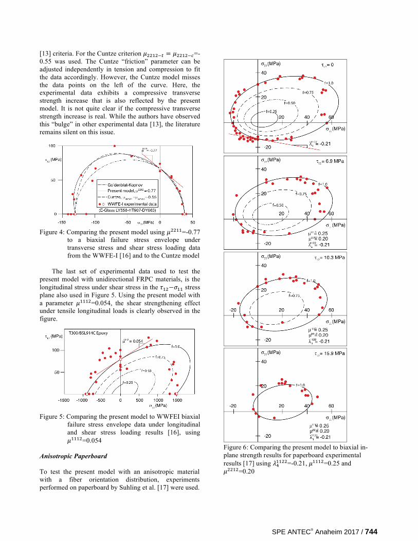
Figure 6: Comparing the present model to biaxial in-plane strength results for paperboard experimental results [17] using 𝜆=5566=-0.21, 𝜇5556=0.25 and 𝜇6656=0.20
SPE ANTEC® Anaheim 2017 / 744
In their study, they found that when 𝜏56=0, the Tsai-Wu criterion with 𝐹5566 = −2.297 ⋅ 10E= (MPa)-1 gave the best fit. However, when including all four levels of shear, 𝜏56=0, 𝜏56=6.9 MPa, 𝜏56=10.3 MPa and 𝜏56=15.9 MPa, they had to drop the longitudinal - transverse stress interaction tensor component (𝐹5566 = 0) to achieve an overall better fit. This compromised somewhat the results at 𝜏56=0, because the tilt of the elliptical failure surface and observed in the experimental results is lost when no stress interaction exists. On the other hand, in addition to including the stress interaction strength tensor 𝐹5566, the present model is able to include both shear stress - normal stress interactions 𝐹5556 and 𝐹6656, by adjusting 𝜆=5556, 𝜇5556and 𝜇6656, respectively. Figure 6 compares the strength data within the 𝜎55−𝜎66 stress plane at the four different shear levels to the present model. It is clear that by including all three stress interaction strength tensor components, a very good match between model and experiments was achieved. Two-ply plain weave CFRP laminate
To validate the present model against failure data from woven fabric composite materials, experiments by Mallikarachchi and Pellegrino [18] were used. The Gol’denblat and Kopnov data presented sufficient information to show that the 𝜎55−𝜎66 plane failure surface does not have a tilt and is therefore relatively circular. This is in agreement with the failure criterion developed in Greece by Theocaris [8] as well as his experimental work dealing with weaves [19]. The present model can fit the data used in the Gol’denblat and Kopnov paper very well, as can be seen in Figure 7. There is sufficient data available to evaluate F5566 at three locations in the Gol’denblat and Kopnov experimental data for a textile composite [5]. The authors computed the three slopes which resulted in the same longitudinal – transverse stress interaction tensor component of approximately 𝐹5566 =1.8 ∙ 10E` (MPa)-1.
To validate the present model against failure data from woven fabric composite materials with a combined longitudinal, transverse and planar shear stresses, experiments performed by Mallikarachchi and Pellegrino [18] on two-ply T300-1k/ Hexcel 913 plain weave laminates were used. In their own analysis, Mallikarachchi and Pellegrino used the Tsai-Wu model with a four-fold symmetry about the third axis of the laminate, resulting in 𝐹55 = 𝐹66, 𝐹5556 = 𝐹6656, etc. and used Tsai-Wu’s 𝐹5556 longitudinal - transverse stress interaction tensor component with 𝑓56 = − 5
6. As a result,
as shown in Figure 8, their failure surface was elliptical, contradicting the findings of Gol’denblat and Kopnov [5] as well as Theocaris [19]. The present model was fit in such a way that it predicts a nearly circular failure surface by using 𝜆=5556=-0.35. Furthermore, the parameters µ5556
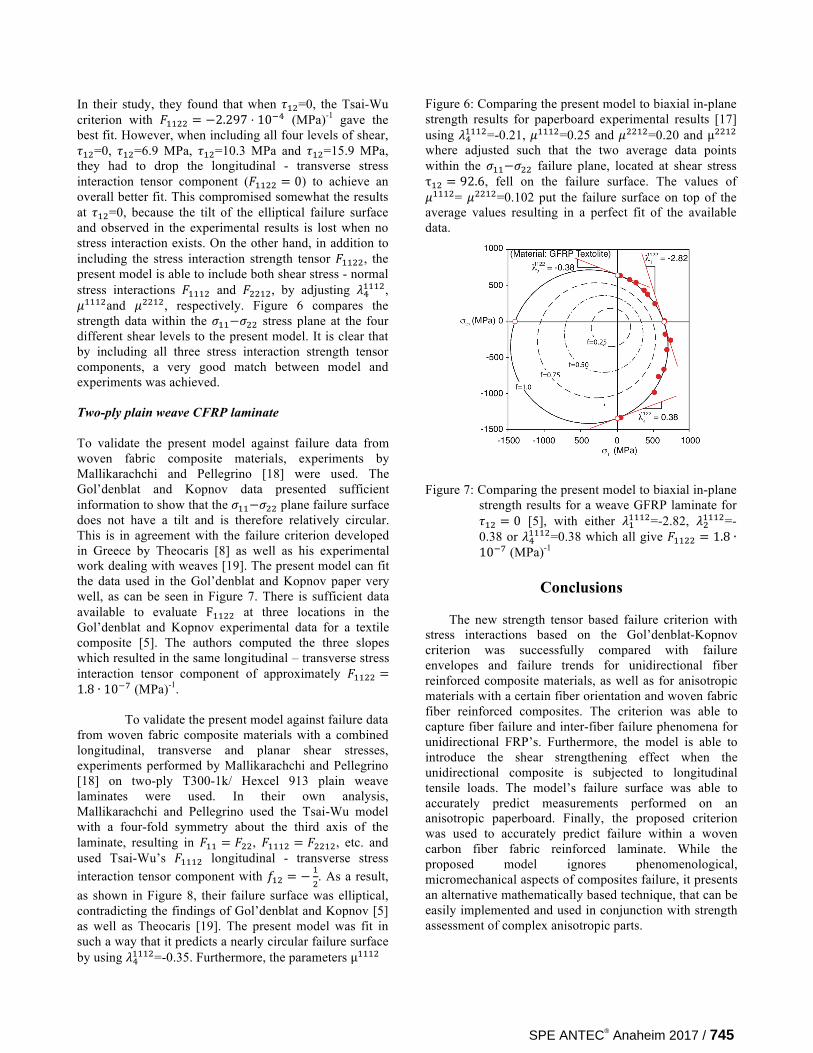
Figure 6: Comparing the present model to biaxial in-plane strength results for paperboard experimental results [17] using 𝜆=5556=-0.21, 𝜇5556=0.25 and 𝜇6656=0.20 and µ6656 where adjusted such that the two average data points within the 𝜎55−𝜎66 failure plane, located at shear stress τ56 = 92.6, fell on the failure surface. The values of 𝜇5556= 𝜇6656=0.102 put the failure surface on top of the average values resulting in a perfect fit of the available data.
Figure 7: Comparing the present model to biaxial in-plane
strength results for a weave GFRP laminate for 𝜏56 = 0 [5], with either 𝜆55556=-2.82, 𝜆65556=-0.38 or 𝜆=5556=0.38 which all give 𝐹5566 = 1.8 ∙10E` (MPa)-1
Conclusions
The new strength tensor based failure criterion with
stress interactions based on the Gol’denblat-Kopnov criterion was successfully compared with failure envelopes and failure trends for unidirectional fiber reinforced composite materials, as well as for anisotropic materials with a certain fiber orientation and woven fabric fiber reinforced composites. The criterion was able to capture fiber failure and inter-fiber failure phenomena for unidirectional FRP’s. Furthermore, the model is able to introduce the shear strengthening effect when the unidirectional composite is subjected to longitudinal tensile loads. The model’s failure surface was able to accurately predict measurements performed on an anisotropic paperboard. Finally, the proposed criterion was used to accurately predict failure within a woven carbon fiber fabric reinforced laminate. While the proposed model ignores phenomenological, micromechanical aspects of composites failure, it presents an alternative mathematically based technique, that can be easily implemented and used in conjunction with strength assessment of complex anisotropic parts.
SPE ANTEC® Anaheim 2017 / 745
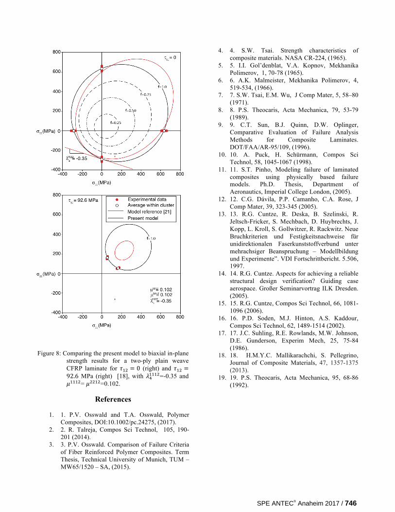
Figure 8: Comparing the present model to biaxial in-plane strength results for a two-ply plain weave CFRP laminate for 𝜏56 = 0 (right) and 𝜏56 =92.6 MPa (right) [18], with 𝜆=5556=-0.35 and 𝜇5556= 𝜇6656=0.102.
References
1. 1. P.V. Osswald and T.A. Osswald, Polymer
Composites, DOI:10.1002/pc.24275, (2017). 2. 2. R. Talreja, Compos Sci Technol, 105, 190-
201 (2014). 3. 3. P.V. Osswald. Comparison of Failure Criteria
of Fiber Reinforced Polymer Composites. Term Thesis, Technical University of Munich, TUM – MW65/1520 – SA, (2015).
4. 4. S.W. Tsai. Strength characteristics of composite materials. NASA CR-224, (1965).
5. 5. I.I. Gol’denblat, V.A. Kopnov, Mekhanika Polimerov, 1, 70-78 (1965).
6. 6. A.K. Malmeister, Mekhanika Polimerov, 4, 519-534, (1966).
7. 7. S.W. Tsai, E.M. Wu, J Comp Mater, 5, 58–80 (1971).
8. 8. P.S. Theocaris, Acta Mechanica, 79, 53-79 (1989).
9. 9. C.T. Sun, B.J. Quinn, D.W. Oplinger, Comparative Evaluation of Failure Analysis Methods for Composite Laminates. DOT/FAA/AR-95/109, (1996).
10. 10. A. Puck, H. Schürmann, Compos Sci Technol, 58, 1045-1067 (1998).
11. 11. S.T. Pinho, Modeling failure of laminated composites using physically based failure models. Ph.D. Thesis, Department of Aeronautics, Imperial College London, (2005).
12. 12. C.G. Dávila, P.P. Camanho, C.A. Rose, J Comp Mater, 39, 323-345 (2005).
13. 13. R.G. Cuntze, R. Deska, B. Szelinski, R. Jeltsch-Fricker, S. Mechbach, D. Huybrechts, J. Kopp, L. Kroll, S. Gollwitzer, R. Rackwitz. Neue Bruchkriterien und Festigkeitsnachweise für unidirektionalen Faserkunststoffverbund unter mehrachsiger Beanspruchung – Modellbildung und Experimente”. VDI Fortschrittbericht. 5.506, 1997.
14. 14. R.G. Cuntze. Aspects for achieving a reliable structural design verification? Guiding case aerospace. Großer Seminarvortrag ILK Dresden. (2005).
15. 15. R.G. Cuntze, Compos Sci Technol, 66, 1081-1096 (2006).
16. 16. P.D. Soden, M.J. Hinton, A.S. Kaddour, Compos Sci Technol, 62, 1489-1514 (2002).
17. 17. J.C. Suhling, R.E. Rowlands, M.W. Johnson, D.E. Gunderson, Experim Mech, 25, 75-84 (1986).
18. 18. H.M.Y.C. Mallikarachchi, S. Pellegrino, Journal of Composite Materials, 47, 1357-1375 (2013).
19. 19. P.S. Theocaris, Acta Mechanica, 95, 68-86 (1992).
SPE ANTEC® Anaheim 2017 / 746