
#84631 MicroLux 7x16 Mini Lathe Instruction Manual x 16” Variable Speed Mini Lathe Instruction...
16
7” x 16” Variable Speed Mini Lathe Instruction Manual Made in China for 340 Snyder Avenue Berkeley Heights, NJ 07922 For technical assistance, call 908-464-1094 Monday thru Friday, 1pm to 5pm ET ©Micro-Mark MM050310 Please read and understand all instructions before using this tool. Note: These instructions will show you how to assemble this machine, work its controls and maintain it for long life. It is not intended as an educational course on how to make parts using a lathe. #84631
Transcript of #84631 MicroLux 7x16 Mini Lathe Instruction Manual x 16” Variable Speed Mini Lathe Instruction...

7” x 16” Variable Speed Mini LatheInstruction Manual
Made in China for
340 Snyder AvenueBerkeley Heights, NJ 07922
For technical assistance, call 908-464-1094 Monday thru Friday, 1pm to 5pm ET©Micro-Mark
MM050310
Please read and understand all instructions before using this tool.
Note: These instructions will show you how to assemble this machine, work its controls and maintain it for long life.
It is not intended as an educational course on how to make parts using a lathe.
#84631

2
Maximum swing over bed 7” diameterDistance between centers 16”Spindle taper Morse No. 3 (MT3)Tailstock taper Morse No. 2 (MT2)Spindle bore .787” (20 mm)Cross slide travel 2.559” (65 mm)Compound slide travel 2.165” (55 mm)Spindle speed (continuously variable) 0 to 2500 rpm approx.Thread cutting 12 to 52 TPI in 18 stepsMotor Power 500 Watts
SPECIFICATIONS
IMPORTANT SAFETY INSTRUCTIONSREAD ALL INSTRUCTIONS AND WARNINGS BEFORE USING THIS TOOL.
OperatorCOMMON SENSE AND CAUTION ARE FACTORS WHICH CANNOT BE BUILT INTO ANY PRODUCT. THESE FACTORS MUST BE SUPPLIED BY THE OPERATOR. PLEASE REMEMBER:
1. When using electric tools, machines or equipment, basic safety precautions should always be followed to reduce the risk of fire, electric shock, and personal injury.
2. Keep work area clean. Cluttered areas invite injuries.
3. Consider work area conditions. Do not use machines or power tools in damp, wet or poorly lit locations. Do not expose equipment to rain. Keep work area well lit. Do not use tools in the presence of flammablegases or liquids.
4. Keep children away from the work area.
5. Guard against electric shock. Prevent bodily contact with grounded surfaces, such as pipes, radiators,ranges, and refrigerator enclosures.
6. Stay alert. Never operate equipment if you are tired.
7. Do not operate the product if you are under the influence of alcohol or drugs. Read warning labels on prescriptions to determine if your judgment or reflexes might be impaired.
8. Do not wear loose clothing or jewelry, as they can be caught in moving parts. Contain long hair with a hat or headband.
9. Use eye and ear protection. Always wear:
ANSI approved chemical splash goggles when working with chemicals.
ANSI approved impact safety goggles at other times.
ANSI approved dust mask or respirator when working around metal, wood, and chemical dusts and mists.
A full face shield if you are producing metal or wood filings and/or chips.
10. Keep proper footing and balance at all times.
11. Do not reach over or across running machinery.
12. Always check that adjusting keys and wrenches are removed from the tool or machine before starting it.
13. Do not carry any tool with your finger on the start button.
14. When servicing, use only identical replacement parts.

3
Before OperationBe sure the switch is OFF when not in use and before plugging in to wall outlet.
Do not use inappropriate attachments in an attempt to exceed the toolʼs capacity. Approved accessories areavailable from Micro-Mark (1-800-225-1066), www.micromark.com.
Check for damaged parts. Before using any tool, any part that appears damaged should be carefully checkedto determine that it will operate properly and perform its intended function.
Check for alignment and binding of all moving parts, broken parts or mounting fixtures or any other conditionthat may affect proper operation. Any part that is damaged should be properly repaired or replaced by a qualifiedtechnician.
Do not use the tool if any switch does not properly turn off and on.
Operation Never force the tool or attachment to do the work of a larger industrial tool. The machine will do a job better andmore safely at the rate for which it was intended.
Do not carry the tool by its power cord.
Always unplug the cord by the plug. Never yank on the cord to disconnect the machine from the wall outlet.
Always turn off the machine before unplugging.
IF YOU QUESTION THE SAFE CONDITION OF THE MACHINE, DO NOT OPERATE IT!
Electrical Grounding InstructionsThis machine has a three-prong plug. The third (round) prong is the ground. Plug this cord only into a three-prong receptacle. Do not attempt to defeat the protection the ground wire provides by cutting off the round prong. Cutting off the ground will result in a safety hazard and void the warranty.
DO NOT MODIFY THE PLUG IN ANY WAY.IF YOU ARE NOT SURE ABOUT THE CONNECTIONS,
CALL A QUALIFIED ELECTRICIAN.

4
1. Gear cover
2. Headstock
3. 3-jaw chuck
4. Cutter guard
5. Tool post
6. Cross-slide
7. Compound slide
8. Tailstock
9. Cam action tailstock handle
10. Tailstock spindle feed handle
11. Bed
12. Lead screw
13. Compound slide feed handle
14. Thread dial indicator table
15. Automatic feed lever
16. Apron
17. Dial
18. Cross-slide feed Handle
19. Carriage/saddle Longitudinal Feed Wheel
20. Emergency stop switch
21. Green lamp
22. Forward/Reverse switch
23. Yellow lamp
24. Fuse cover
25. Speed control knob
26. Digital readout port (with protective cap)
LATHE FEATURES
CONTROL PANEL
2
20 21 22 23 24 25 26
1 3 54 6 7 8 9 10
11
13 121417 16 151819
5
1. HeadstockThe motor drives the spindle via an internal tooth belt. Spindle speed is continuously variable, and is regulated by the speed control knob (20) located on the main control panel.
The spindle is provided with an internal No. 3 Morse taper (MT3) to accommodate a center, or for use with a face plate or turning clamp.
The 3-jaw self-centering chuck (3) is mounted on the spindle flange. To remove the chuck, remove the three securing nuts on the rear of the flange,and pull it free together with the three mounting studs.
Three external jaws are also supplied to extend the capacity of the chuck. Their use and method of assembly is described under “Accessories,” page 12.
The spindle has 6 holes drilled in its flange to accommodate a range of attachments, such as a face plate, 4-jaw chuck, etc. (see Accessories).
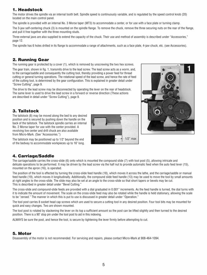
2. Running GearThe running gear is protected by a cover (1), which is removed by unscrewing the two hex screws.
The gear train, shown in fig. 1, transmits drive to the lead screw. The lead screw acts as a worm, and, to the carriage/saddle and consequently the cutting tool, thereby providing a power feed for threadcutting or general turning operations. The rotational speed of the lead screw, and hence the rate of feedof the cutting tool, is determined by the gear configuration. This is explained in greater detail under“Screw Cutting”, page 9.
The drive to the lead screw may be disconnected by operating the lever on the rear of headstock. The same lever is used to drive the lead screw in a forward or reverse direction (These actions are described in detail under “Screw Cutting”), page 9.
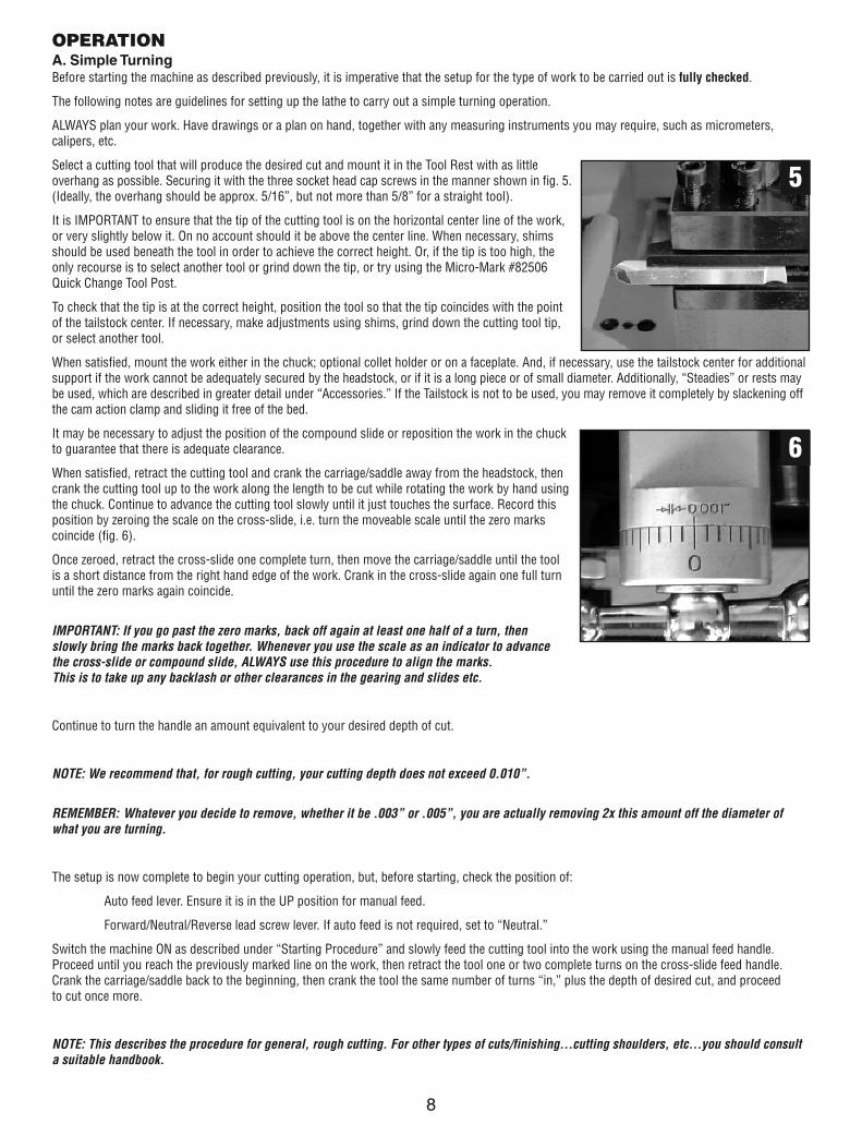
3. TailstockThe tailstock (8) may be moved along the bed to any desiredposition and is secured by pushing down the handle on theback of the tailstock. The tailstock spindle carries an internalNo. 2 Morse taper for use with the center provided. A revolving live center and drill chuck are also available from Micro-Mark. (See “Accessories.”)
The tailstock may be positioned up to 1/2" beyond the end of the bedway to accommodate workpieces up to 16" long.
4. Carriage/SaddleThe carriage/saddle carries the cross-slide (6) onto which is mounted the compound slide (7) with tool post (5), allowing intricate and delicate operations to be performed. It may be driven by the lead screw via the half nut to provide automatic feed when the auto feed lever (15),mounted on the apron (16), is operated.
The position of the tool is effected by turning the cross-slide feed handle (18), which moves it across the lathe, and the carriage/saddle or manualfeed handle (19), which moves it longitudinally. Additionally, the compound slide feed handle (13) may be used to move the tool by small amounts at right angles to the cross-slide. The slide may also be set at an angle to the cross-slide so that short tapers or bevels may be cut. This is described in greater detail under “Bevel Cutting.”
The cross-slide and compound-slide feeds are provided with a dial graduated in 0.001” increments. As the feed handle is turned, the dial turns with it to indicate the amount of movement. The scale on the cross-slide feed may also be rotated while the handle is held stationary, allowing the scale to be “zeroed.” The manner in which this is put to use is discussed in greater detail under “Operation.”
The tool post carries 8 socket head cap screws which are used to secure a cutting tool in any desired position. Four tool bits may be mounted forquick and easy changes. Two are shown mounted.
The tool post is rotated by slackening the lever on its top a sufficient amount so the post can be lifted slightly and then turned to the desiredposition. There is a 90˚ stop pin under the tool post to aid in this indexing.
ALWAYS be sure the post, and hence the tool, is secure by tightening the lever firmly before attempting to cut.
5. MotorDisassembly of the motor is not recommended. For servicing and repairs, please contact Micro-Mark at 908-464-1094.
1
1/2” max

6
Unpacking and Preparing for Use (See assembly instructions)Upon receipt, carefully unpack the lathe and inspect it to ensure that no damage was suffered in transit and to account for all parts. Should any damage be apparent, or parts are missing, please contact the carrier and Micro-Mark immediately.
The following loose items are to be found in the packing case (fig. 2):
4 Rubber Feet*
4 M6 pan head Screws*
4 Hex Keys
1 Chuck key
1 Plastic Oil Container
1 Spare Fuse
2 Plastic Handles w/Nuts and Bolts*
1 MT-2 Dead Center for Tailstock
3 External Jaws for 3-Jaw Chuck
2 Open End Wrenches, 8/10 mm and 14/17 mm
1 Gear Set: 65, 60, 57, 55, 50, 45, 40 (2), 35, 30
*Not shown
The machine is very heavy. With an assistant, lift it onto a sturdy surface or workbench. Remove all traces of preservative with a good quality solvent, then lightly oil all machined surfaces.
You will notice that, for transit purposes, the cross slide feed handle has been mounted in reverse. Remove it by unscrewing the socket head screwthat secures it, and mount it in the correct way. Then turn all feed handles to ensure they move freely, evenly and smoothly.
Attach the plastic handles to the rims of the manual feed and tailstock feed hand wheels, ensuring that the nuts are tight and the handles spin freelyaround the bolts without excessive end play.
The carriage/saddle, cross-slide and compound slide adjustments are all factory set to ensure smooth movement in both directions. However, if the adjustments have been upset during transit (indicated by stiff or erratic movement), refer to “Settings and Adjustments” for the methods of adjustment.
All hex keys and wrenches necessary to carry out the various adjustments are supplied together with a chuck key for the 3-jaw chuck and a spare fuse (F10AL250V). The fuse holder is located on the top of the main control panel.
The four rubber feet are to be attached to the underside of the bed with the four M6 pan head screws in the tapped holes provided. These screws are also used to secure the chip tray. To provide maximum stability and additional safety, we strongly recommend that you secure the lathe to a firm foundation as described under “Mounting the Lathe” below.
The three external jaws for the 3-jaw self-centering chuck extend the capacity of the chuck and are discussed in greater detail under “Accessories.”
INSTALLATIONMounting the LatheThe lathe should be mounted on a sturdy workbench of sufficient heightso that you do not need to bend your back to perform normal operations.The machine is very heavy, so get assistance from another person whenmoving the machine.
Provide adequate overhead lighting so that you will not be working inyour own shadow.
We strongly recommend that the machine be firmly bolted to a sturdyworkbench using the same tapped holes used to secure the feet to thelathe. This will provide added stability and, consequently, safety.
To do this, remove the four M6 screws which secure the rubber feet and chip tray to the machine (if already fitted). Remove the rubber feet.They will no longer be used.
Drill four 1/4” clearance holes in the bench top at the locations shown in fig. 3 and, with appropriate length M6 x 1.0 bolts or screws with flat washers (not supplied), secure the lathe to the worktop ensuring that thechip tray is in place.
Alternatively, if you do not wish for a permanent installation, you may secure the lathe to a 5/8” thick plywood board with a minimum recommendedsize of 12” x 32”, centering the mounting holes on the board. When the lathe is in use, the board should be clamped to workbench with C-clamps.
2
22-1/2”
2-27/32”
3

STARTING PROCEDUREA. During Installation – Initial Start (fig. 4)Taking all precautions previously stated, turn the speed control knob fully counter-clockwise, settingit to OFF. (You will NOT hear an audible click.)
Be sure the cross-slide is well away from the chuck and the automatic feed lever is in its disengagedposition (lever is UP). Insert the electric plug into the wall socket.
To start the lathe, follow the procedure below:
• Check that the red emergency switch is latched down and that the Forward/Reverse switch is in theforward position. (If the machine has been shut down in an emergency, also make sure that anytrouble has been cleared from the machine and the green light is off. If the green light is on, lift theemergency cover and press the red button or unplug the machine from the wall outlet).
• Release the red emergency stop button by pressing in the safety lock on the left side of the switch and then lifting up. You will find a red (OFF) anda green (ON) button. Press the green button to activate/power the panel. The green light will illuminate, and the digital readout should display fourzeros and the word “STOP” in the lower right corner of the display. (If so equipped.) See note below.
• If all is still clear, slowly rotate the speed control knob (clockwise) to begin rotation of the spindle drive system and see that the readout display hasactivated and the word “STOP” has disappeared.
Run the machine for a total of 5 minutes, and during this time, gradually increase the spindle speed to its maximum. Continue to run the machine atthis speed for at least 2 minutes, then shut it off. Disconnect the plug from the wall outlet.
Check that all components are still secure and working freely and correctly. Check also to ensure the mountings are secure.
Repeat the procedure again, but this time in the reverse direction.
Should any adjustments be necessary, refer to the appropriate section under “Settings and Adjustments”.
B. Starting Under Normal Conditions (fig. 4)• Take all necessary precautions previously stated, and ensure the workpiece can rotate fully without obstruction.
• Always have the speed range set to off before switching machine on.
• Set the Forward/Reverse switch on the main control panel to the desired position.
• Engage or ensure the auto feed lever is disengaged, depending upon whether or not automatic feed is required.
IMPORTANT: This should ALWAYS be a deliberate, conscious action.
NOTE: If auto feed is required, the lead screw Forward/Neutral/Reverse lever should be set to the desired position. If auto feed is not required, the lever may be set to Neutral. To do this, grasp the knurled handle on the back of the headstock and pull out against spring pressure. Holding the handle in this position, move the lever until the pointed end is located in the middle pit mark in the casing.
• Proceed to start the machine as described in Section A above.
• If you are done working, or if the machine is to be left unattended, close the emergency off button and disconnect the plug from the wall outlet.
ATTENTION: The power supply system of the 120v AC machine has an automatic overload protective device. If the machine is overloaded, themotor will automatically shut down, and the yellow lamp will light and the readout will display “ERR” (if equipped).
7
4
CAUTION:Always turn the speed control to the OFF position before starting lathe. Starting the lathewith the speed control set to a higher speed can damage the speed control circuit board.
IMPORTANT!First, rotate the RPM to OFF (counter clockwise). The display should read four zeros (0000) and the word “STOP” should reappear in the lower right corner, if equipped. You will now notice the yellowoverload light has gone out. While it is possible to start spinning again simply by rotating the RPM knob at this point, we advise you to push down smartly the Emergency Stop Button and investigate
the cause of the overload. Once you have cleared the situation, then, and only then, should you begin the start up sequence in this section.
Note: the big red emergency stop button must be pressed smartly (with some force) to activate the internal shut off system properly. If the green light remains lit, power is still available to the motor,
so be sure to press the red button hard-enough to shut down the power.
8
OPERATIONA. Simple TurningBefore starting the machine as described previously, it is imperative that the setup for the type of work to be carried out is fully checked.
The following notes are guidelines for setting up the lathe to carry out a simple turning operation.
ALWAYS plan your work. Have drawings or a plan on hand, together with any measuring instruments you may require, such as micrometers,calipers, etc.
Select a cutting tool that will produce the desired cut and mount it in the Tool Rest with as little overhang as possible. Securing it with the three socket head cap screws in the manner shown in fig. 5.(Ideally, the overhang should be approx. 5/16”, but not more than 5/8” for a straight tool).
It is IMPORTANT to ensure that the tip of the cutting tool is on the horizontal center line of the work,or very slightly below it. On no account should it be above the center line. When necessary, shimsshould be used beneath the tool in order to achieve the correct height. Or, if the tip is too high, theonly recourse is to select another tool or grind down the tip, or try using the Micro-Mark #82506Quick Change Tool Post.
To check that the tip is at the correct height, position the tool so that the tip coincides with the pointof the tailstock center. If necessary, make adjustments using shims, grind down the cutting tool tip,or select another tool.
When satisfied, mount the work either in the chuck; optional collet holder or on a faceplate. And, if necessary, use the tailstock center for additionalsupport if the work cannot be adequately secured by the headstock, or if it is a long piece or of small diameter. Additionally, “Steadies” or rests maybe used, which are described in greater detail under “Accessories.” If the Tailstock is not to be used, you may remove it completely by slackening offthe cam action clamp and sliding it free of the bed.
It may be necessary to adjust the position of the compound slide or reposition the work in the chuckto guarantee that there is adequate clearance.
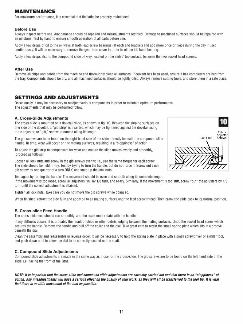
When satisfied, retract the cutting tool and crank the carriage/saddle away from the headstock, thencrank the cutting tool up to the work along the length to be cut while rotating the work by hand usingthe chuck. Continue to advance the cutting tool slowly until it just touches the surface. Record thisposition by zeroing the scale on the cross-slide, i.e. turn the moveable scale until the zero markscoincide (fig. 6).
Once zeroed, retract the cross-slide one complete turn, then move the carriage/saddle until the tool is a short distance from the right hand edge of the work. Crank in the cross-slide again one full turnuntil the zero marks again coincide.
IMPORTANT: If you go past the zero marks, back off again at least one half of a turn, then slowly bring the marks back together. Whenever you use the scale as an indicator to advancethe cross-slide or compound slide, ALWAYS use this procedure to align the marks. This is to take up any backlash or other clearances in the gearing and slides etc.
Continue to turn the handle an amount equivalent to your desired depth of cut.
NOTE: We recommend that, for rough cutting, your cutting depth does not exceed 0.010”.
REMEMBER: Whatever you decide to remove, whether it be .003” or .005”, you are actually removing 2x this amount off the diameter ofwhat you are turning.
The setup is now complete to begin your cutting operation, but, before starting, check the position of:
Auto feed lever. Ensure it is in the UP position for manual feed.
Forward/Neutral/Reverse lead screw lever. If auto feed is not required, set to “Neutral.”
Switch the machine ON as described under “Starting Procedure” and slowly feed the cutting tool into the work using the manual feed handle. Proceed until you reach the previously marked line on the work, then retract the tool one or two complete turns on the cross-slide feed handle.Crank the carriage/saddle back to the beginning, then crank the tool the same number of turns “in,” plus the depth of desired cut, and proceed to cut once more.
NOTE: This describes the procedure for general, rough cutting. For other types of cuts/finishing...cutting shoulders, etc...you should consulta suitable handbook.
5
6

9
B. Simple Turning With Power FeedThe same basic setup is used as described previously, except that, before starting, the lead screw F/N/R Lever (on the rear of headstock) is set tothe “Forward” position and the auto feed lever (15) is operated in order to drive the carriage/saddle. As mentioned previously, the rotational speedof the lead screw, and hence the rate of feed of the tool, is dependent upon the gear configuration of the gear train. The feed rate for normal turningis considerably less than that used for screw cutting.
The lathe is factory-configured for normal turning; however, if you have been screw cutting, always remember to reset the gear configuration to thatfor normal turning. Please refer to the chart on a later page which shows the gear configuration and an explanation of how to change the gears.
1. Taking all precautions previously mentioned, position the cutting tool a short distance to the right of the workpiece with the appropriate depth of cut set on the cross-slide.
2. Ensure the lead screw F/N/R lever is set to “Forward” and select “Forward” on the Forward/Reverse switch on the main control panel.Switch on the machine.
3. Turn the knob to achieve your desired spindle speed with your right hand and push down on the auto feed lever until the nut becomesfirmly engaged with the lead screw.
IMPORTANT: Your left hand should always be free in order to hit the emergency stop should it become necessary.
4. Carefully observe the movement of the tool and as it approaches the mark on the surface (denoting the end of cut), pull the auto feedlever UP sharply and ensure it stays UP. If a degree of accuracy is required, it is recommended that you finish the cut by hand.
NOTE: If you require a shoulder with perfectly clean corners, then you need to use an appropriately shaped tool.
5. Retract the tool one or two complete turns on the cross-slide feed. Then crank the carriage/saddle so that the tool is at the start pointonce again. Advance the tool the same number of turns, plus the depth of cut, and when ready, push down the auto feed lever and proceed to take another cut.
C. Bevel CuttingBevel cutting involves the use of the compound slide, which is mounted on thecross-slide and set at right angles to it (indicated by the zero mark on the bodyof the cross-slide) for all normal cutting operations.
To set the compound slide so that the cutting tool will cut a bevel, first retractthe slide until the two socket head screws (A) are revealed as shown in fig. 7.
Loosen the screws sufficiently to allow the compound slide to be turned to thedesired angle, as indicated on the scale, and secure the slide in this position byretightening the socket head screws.
The taper, or bevel, is cut by setting the cross-slide appropriately, then using thecompound slide feed handle to advance the cutting tool in the direction of the arrow as shown in fig. 8.
D. Screw CuttingThis operation requires a degree of skill and accuracy, and should not be attempted unless you are completely familiar with all aspects of the lathe.Essentially, the carriage/saddle will move towards the headstock under power, the same as cutting with auto feed, except the rate of feed is greater,as determined by the gear configuration. The cutting tool, therefore, is moving ever closer to the rotating chuck. Great care and concentration mustbe exercised to ensure that the two do not meet when the machine is operating, as the damage caused would be disastrous.
The lathe is supplied with a lead screw that will produce imperial threads in a range from 12 to 52 threads per inch. It is important to remember thatthe type of thread you need to cut (i.e., UNF, BA, BSP, BSW, etc.) will be totally dependant upon the cutting tool profile, as profiles differ from threadto thread. For detailed information regarding screw cutting techniques, cutting tools, etc., you should consult a suitable handbook or obtain adviceand/or training from a qualified person.
The general procedure for screw cutting is as follows:
1. Try to get as much distance from the chuck to the end of the proposed screw thread as possible. If your design allows, cut a “run-off”into the work piece which is of a smaller diameter than the root diameter of the proposed screw thread.
2. Install the appropriate gears for the thread required, and correctly mount the cutting tool. Set your required depth of cut, and positionthe tool ready to begin cutting.
Note: Depth of cut is vitally important and may be calculated or obtained from an appropriate reference manual.
3. Take all necessary precautions previously stated, and start the machine with the automatic feed lever in its disengaged position (UP).
4. Engage the auto-feed lever sharply, turn the Forward/Reverse (F/R) switch to “Forward.” As the tool approaches the end of the desired thread, push down on the red button that has been revealed under the emergency button to stop. Do not disengage the auto-feed lever.
5. Retract the tool using the cross-slide feed handle, noting the exact position on the scale and the exact number of turns. Turn the switchto “Reverse”, then press the green button and the carriage/saddle winds back to the beginning and press the red button again. Nowchange the Directional Switch to Forward. Restart the tool by winding IN the cross-slide the exact number of turns previously woundOUT and then continue to wind IN the to the desired depth of cut. Press the green button to begin again.
6. Repeat as required in this manner until the thread is completed.
87

CHANGING GEARS FOR SCREW CUTTINGThe lead screw is driven via a gear train and a gear on the spindle. The gear ratio will determine the rotational speed of the lead screw with relation tothe spindle, i.e., one turn of the spindle will turn the lead screw an amount determined by the gear ratio.
By setting the gears to a known ratio, we can therefore produce threads of a known size, and as the lead screw supplied produces Imperial threads,the known values will be in Threads Per Inch (TPI).
As previously mentioned, the actual thread produced will be totally dependent upon the profile of the cutting tool. It is not within the scope of thismanual to provide detailed information regarding types of cutting tool, cutting speeds and working with various types of material etc, and it is stronglyadvised that you consult appropriate handbooks or seek advice from a qualified person.
The chart below shows the thread sizes that may be cut using the gearconfiguration shown in the corresponding columns.
NOTE: The factory setup for the lathe provides for normal turningusing the power or auto feed, and the gear configuration is as follows:Gear A 20T; Gear B 80T; Gear C 20T, Gear D 80T.
In order to changethe gears, ensure themachine is switchedOFF and disconnectedfrom the wall outlet.Remove the gear traincover which is securedwith two socket headscrews.
Gear A may beconsidered as thedriver, and gear Das the driven gear.
When a simple geartrain is configured, asillustrated in fig. 9, gearB acts as an idler andits size is therefore irrelevant – any convenient gear willsuffice to connect A and D. This is denoted by a blank space in thecolumn in the gear chart.
The positions of the shafts carrying gears A and D are fixed;therefore, all adjustments are carried out on the shaft carrying gearsB and C and the adjuster “A”, shown in fig. 9.
1. Unscrew the hex socket head screws securing gears A and D,followed by the screw securing gears B and C.
2. To allow the gears B and C to disengage completely and toprovide for easier reassembly, unscrew the nut securing theshaft carrying B and C and the nut securing the adjuster A.
3. Remove the gears, taking care to retain the small keys on eachshaft, and replace with those necessary to produce your screwthread. They may be mounted either way round. The number ofteeth on each gear is clearly marked. Replace the securingscrews, ensuring the flat washer bears up against the gear hubin each case.
NOTE: If a compound gear train is required (B), ensure the spacer,which is keyed to the shaft carrying gear D, is located on the shaftBEFORE the gear, in order to align gear D with gear C.
4. Proceed to move the shaft carrying B and C and the adjuster“A” so that all gears mesh correctly, then tighten the adjustersecuring nuts. This may take one or two attempts, but makesure there is as little backlash as possible without beingover-tight (turn the spindle by hand to test for backlash).
Replace the cover and secure with the two hex socket head bolts.
Threads GearPer Inch A B C D
12 40 3013 40 65 60 3014 40 3516 40 4018 40 4519 40 50 60 5720 40 5022 40 5524 40 6026 40 6528 20 3532 20 4036 20 4538 20 50 60 5740 20 5044 20 5548 20 6052 20 65
Examples:1. Fig. A
To cut 12 TPI, use40T in position A,30T in position Dand any convenientgear in position B toconnect A and D.
GEAR CHART FOR CUTTING IMPERIAL THREADS
9Spindle
A
B/C
D
2. Ref. Fig. BTo cut 13 TPI, use40T in position A,65T in position B60T in position C30T in position D
10
Fig. A
Fig. B
11
MAINTENANCEFor maximum performance, it is essential that the lathe be properly maintained.
Before UseAlways inspect before use. Any damage should be repaired and misadjustments rectified. Damage to machined surfaces should be repaired with an oil stone. Test by hand to ensure smooth operation of all parts before use.
Apply a few drops of oil to the oil ways at both lead screw bearings (at each end bracket) and add more once or twice during the day if used continuously. It will be necessary to remove the gear train cover in order to oil the left hand bearing.
Apply a few drops also to the compound slide oil way, located on the slides’ top surface, between the two socket head screws.
After UseRemove all chips and debris from the machine and thoroughly clean all surfaces. If coolant has been used, ensure it has completely drained fromthe tray. Components should be dry, and all machined surfaces should be lightly oiled. Always remove cutting tools, and store them in a safe place.
SETTINGS AND ADJUSTMENTSOccasionally, it may be necessary to readjust various components in order to maintain optimum performance. The adjustments that may be performed follow:
A. Cross-Slide AdjustmentsThe cross-slide is mounted on a dovetail slide, as shown in fig. 10. Between the sloping surfaces on one side of the dovetail, a “gib strip” is inserted, which may be tightened against the dovetail using three adjuster, or “gib,” screws mounted along its length.
The gib screws are to be found on the right hand side of the slide, directly beneath the compound slidehandle. In time, wear will occur on the mating surfaces, resulting in a “sloppiness” of action.
To adjust the gib strip to compensate for wear and ensure the slide moves evenly and smoothly,proceed as follows:
Loosen all lock nuts and screw in the gib screws evenly; i.e., use the same torque for each screw. The slide should be held firmly. Test by trying to turn the handle, but do not force it. Screw out each gib screw by one quarter of a turn ONLY, and snug up the lock nuts
Test again by turning the handle. The movement should be even and smooth along its complete length. If the movement is too loose, screw all adjusters “in” by 1/8 turn, and re-try. Similarly, if the movement is too stiff, screw “out” the adjusters by 1/8turn until the correct adjustment is attained.
Tighten all lock nuts. Take care you do not move the gib screws while doing so.
When finished, retract the side fully and apply oil to all mating surfaces and the feed screw thread. Then crank the slide back to its normal position.
B. Cross-slide Feed HandleThe cross slide feed should run smoothly, and the scale must rotate with the handle.
If any stiffness occurs, it is probably the result of chips or other debris lodging between the mating surfaces. Undo the socket head screw which secures the handle. Remove the handle and pull off the collar and the dial. Take great care to retain the small spring plate which sits in a groove beneath the dial.
Clean the assembly and reassemble in reverse order. It will be necessary to hold the spring plate in place with a small screwdriver or similar tool,and push down on it to allow the dial to be correctly located on the shaft.
C. Compound Slide AdjustmentsCompound slide adjustments are made in the same way as those for the cross-slide. The gib screws are to be found on the left hand side of theslide; i.e., facing the front of the lathe.
NOTE: It is important that the cross-slide and compound slide adjustments are correctly carried out and that there is no “sloppiness” of action. Any misadjustments will have a serious effect on the quality of your work, as they will all be transferred to the tool tip. It is vital that there is as little movement of the tool as possible.
10
External Jaws for 3-Jaw ChuckTo change the jaws, insert the chuck key and open the jaws to their fullest extent. It will then be possibleto remove each jaw in turn.
Replace them with the external jaws, noting the following:
The thread segments of the jaws are progressively stepped as shown in fig. 11. They are also numbered 1 to 3. This is to take into account the lead of the screw thread within the chuck. It is therefore necessaryto assemble the jaws in the correct order.
Place them as shown in fig. 11 and assemble in the same order, clockwise in the slots in the chuck,turning the chuck key as you insert them. Close the jaws fully and check to ensure they all meet at the center. If a jaw is out, open the jaws fully, andretain pressure on the jaw in question while turning the chuck key until it snaps down into position. Re-check to ensure all jaws meet at the center.
Follower and Steady RestsFig. 12 illustrates the steady rest (A) and follower rest (B) assembled to the lathe.They support a long workpiece so that the pressure of thecutting tool does not push it away.
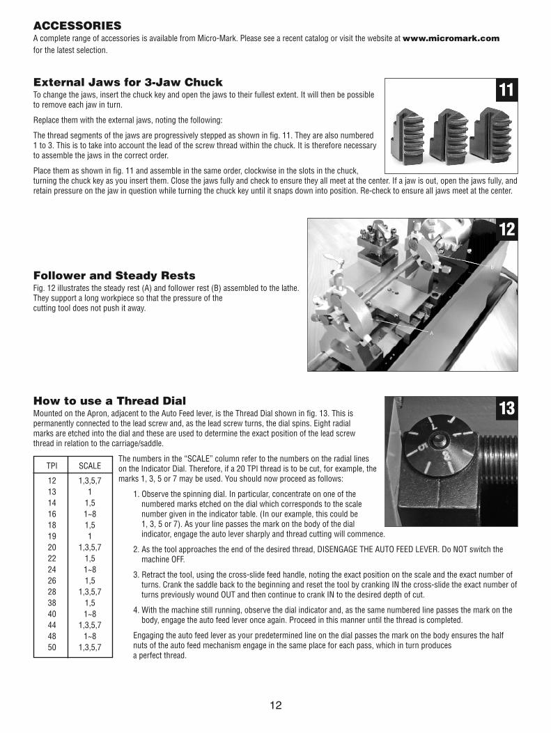
How to use a Thread DialMounted on the Apron, adjacent to the Auto Feed lever, is the Thread Dial shown in fig. 13. This ispermanently connected to the lead screw and, as the lead screw turns, the dial spins. Eight radialmarks are etched into the dial and these are used to determine the exact position of the lead screwthread in relation to the carriage/saddle.
The numbers in the “SCALE” column refer to the numbers on the radial lineson the Indicator Dial. Therefore, if a 20 TPI thread is to be cut, for example, themarks 1, 3, 5 or 7 may be used. You should now proceed as follows:
1. Observe the spinning dial. In particular, concentrate on one of thenumbered marks etched on the dial which corresponds to the scalenumber given in the indicator table. (In our example, this could be 1, 3, 5 or 7). As your line passes the mark on the body of the dialindicator, engage the auto lever sharply and thread cutting will commence.
2. As the tool approaches the end of the desired thread, DISENGAGE THE AUTO FEED LEVER. Do NOT switch themachine OFF.
3. Retract the tool, using the cross-slide feed handle, noting the exact position on the scale and the exact number ofturns. Crank the saddle back to the beginning and reset the tool by cranking IN the cross-slide the exact number ofturns previously wound OUT and then continue to crank IN to the desired depth of cut.
4. With the machine still running, observe the dial indicator and, as the same numbered line passes the mark on thebody, engage the auto feed lever once again. Proceed in this manner until the thread is completed.
Engaging the auto feed lever as your predetermined line on the dial passes the mark on the body ensures the halfnuts of the auto feed mechanism engage in the same place for each pass, which in turn produces a perfect thread.
11
13
12
TPI SCALE
12 1,3,5,713 114 1,516 1~818 1,519 120 1,3,5,722 1,524 1~826 1,528 1,3,5,738 1,540 1~844 1,3,5,748 1~850 1,3,5,7
12
ACCESSORIESA complete range of accessories is available from Micro-Mark. Please see a recent catalog or visit the website at www.micromark.comfor the latest selection.

13

14
1 GB 278-89 - 80206 Bearing 80206 2
2 CN10203 Cover 2
3 GB 70-85 - M5 x 12 Screw M5*12 11
4 C2A0208 Spindle gear 1
5 GB 810-88 - M27x1.5 Nut M27*1.5 2
6 CN10207 Pulley 1
7 CN10204 Spacer 2
8 GB 77-85 - M6 x 25 Screw M6*25 3
9 GB 6170-86 - M6 Nut M6 6
10 SC30201 Headstock Casting 1
11 SC20202 Spindle 1
12 GB1096-79 4x28 Parallel Key 4*28 1
13 GB 96-85 - 6 Washer 6 2
14 500W Brushless motor 500W 1
15 GB 859-87 - 5 Spring Washer 5 9
16 GB 70-85 - M5 x 14 Screw M5*14 7
17 CN11502 Pulley 1
18 GB1096-79 5x18 Parallel Key 5*18 1
19 1.5x100x9 Timing belt 1
20 CN11503 Motor connector 1
21 CN11501 Bracket for motor 1
22 GB 97.1-85 - 5 Washer 5 7
23 GB 77-85 - M6 x 10 Screw M6*10 3
24 GB 70-85 - M6 x 12 Screw M6*12 7
25 GB 6172-86 - M5 Nut M5 4
26 GB 77-85 - M5 x 10 Screw M5*10 5
27 GB 6172-86 - M4 Nut M4 6
28 GB 79-85 - M4 x 16 Screw M4*16 3
29 GB 70-85 - M4 x 8 Screw M4*8 2
30 GB 70-85 - M4 x 12 Screw M4*12 4
31 GB 97.1-85 - 8 Washer 8 2
32 GB 93-87 - M6 Spring washer M6 2
33 GB 70-85 - M6 x 10 Screw M6*10 4
34 GB 70-85 - M8 x 20 Screw M6*20 2
35 C2A0501 Saddle 1
36 C2A0505 Press board 2
37 C2A0502 Cross Slide 1
38 C2A0503A Feeding Screw (Imperial) 1
39 C2A0507 Gib Strip 1
40 C2A0504A Feeding Nut (Imperial) 1
41 C2A0509A Fixing ring (Imperial) 1
42 C2A0508A Dial (Imperial) 2
43 C2A0511 Handle (big) 1
44 C2A0506 Orientation 1
45 C2A0414 Spring patch 2
46 GB 70-85 - M6 x 16 Screw M6*16 3
47 GB308-85 5 Steel ball 1
48 GB 70-85 - M4 x 10 Screw M4*10 4
49 GB 41-86 - M 8 Nut M8 1
50 GB 65-85 - M8 x 55 Screw M8*55 2
51 GB 119-86 - A 5 x 12 Round Pin A5*12 1
52 GB 78-85 - M6 x 12 Screw M6*12 2
53 GB 96-85 - 4 Washer 4 2
54 GB 818-85 - M4 x 8 Screw (H type) 8
55 GB 75-85 - M4 x 10 Screw M4*10 3
56 GB 79-85 - M6 x 8 Screw M6*8 1
57 GB 6170-86 - M4 Nut M4 1
58 GB 77-85 - M4 x 20 Screw M4*20 1
59 C2A0601 Apron 1
60 C2A0604 Shaft 1
61 C2A0607 H/L Gear 1
62 C2A0609 Groove Cam 1
63 C2A0602B Half nut (Imperial) 1
64 C2A0603 Feeding Gear 1
65 C2A030200 Handwheel 2
66 C2A0307 Handle 2
67 C2A0606 Gib strip 1
68 C2A0410 Handle assembly 3
69 C2A0408 Spring 2
70 C2A03A12 __ 1
71 GB 819-85 - M4x10 Screw M4*10 2
72 GB 79-85 - M4 x 12 Screw M4*12 3
73 GB 77-85 - M10 x 50 Screw M10*50 1
74 GB 70-85 - M6 x 25 Screw M6*25 9
75 C2A0401A Compound rest 1
76 C3D0402 Slider 1
77 C2A0403 Gib strip 1
78 C2A0413 Angle block 1
79 C2A0404A Bracket 1
80 C2A0406A Cross feeding screw 1
81 C2A0415 Washer 1
82 C2A0411 Handle 1
83 C2A0407 Positioning pin 1
84 C2A0405 Tool rest 1
85 C2A0409 Handle set 1
86 C2A03A11 Cam brake shaft 1
87 GB 70-85 - M5 x 16 Screw M5*16 1
88 GB 75-85 - M5 x 25 Screw M5*25 1
89 C2A03A10 Brake shaft 1
90 C2A03A13B Connecting plate 1
91 GB 79-85 - M6 x 14 Screw M6*14 1
92 GB 77-85 - M8 x 40 Screw M8*40 1
93 C2A0301B Tailstock casting 1
94 C2A0302 Bottom board 1
Parts List
No. Drawing # Description Qty. No. Drawing # Description Qty.

15
95 C2A03A0102B Plate of tailstock 1
96 C2A0306 Washer 1
97 C2A0304 Tailstock screw 1
98 C2A0305 Flange 1
99 C2A0303 Tailstock 1
100 C2A0309 Handle base 1
101 C2A0308 Clamp 1
102 SC21801 Cover 1
103 SC22511 Switch label 1
104 Magnetic switch 1
105 Connector 1
106 Fuse 1
107 GB 818-85 - M4 x 10 Screw M4*10 2
108 Yellow indicator light 1
109 HY29H Switch 1
110 Power indicator 1
111 Knob 1
112 PC board 1
113 SC21802 Motor cover 1
114 GB 818-85 - M5 x 8 Screw M5*8 9
115 M16 Rubber gasket 1
116 Specification label 1
117 Lightning label 1
118 C3D1803 Defend board 1
119 C2A1820 Dustproof cover 1
120 Power cord 1
121 C2A0104 Left bracket 1
122 C2A0105 Right bracket 1
123 GB 70-85 - M6 x 20 Screw M6*20 5
124 GB1096-79 3x16 Parallel key 3*16 1
125 C2A0106 Washer 1
126 GB 70-85 - M3 x 10 Screw M3*10 5
127 C2A010101 Rubber pad 4
128 GB 818-85 - M6 x 16 Screw M6*16 4
129 GB 71-85 - M5 x 20 Screw M5*20 1
130 GB 6170-86 - M5 Nut M5 1
131 GB 5781-86 - M8x25 Screw M8*25 3
132 SC30101 Bed way 1
133 SC30105 Long rack 1
134 SC30104 Oil ray 1
135 SC30103A Lead screw (Imperial) 1
136 SC22303 Cover 1
137 GB 818-85 - M3 x 6 Screw 2
138 GB 894.1 - 12 Spring washer 2
139 C2A0814 Gear_ 1
140 C2A0811 Gear shaft 2
141 C2A0815 Gear_ 1
142 GB 96-85 - 5 Washer 2
143 GB 93-87 - M5 Spring washer 1
144 GB 818-85 - M5 x 10 Screw 1
145 C2A0805 Bolt 1
146 GB1096-79 3x8 Key 1
147 C2A0812 Gear 1
148 C2A0802 Gear bracket 1
149 GB 70-85 - M5 x 20 Screw 2
150 GB1096-79 3x6 Key 1
151 C2A0816 Gear 2
152 C2A0810 Washer 2
153 C2A0827 Bolt 1
154 C2A0801 Gear retainer 1
155 C2A0804 Shaft 1
156 C2A0813 Sleeve 1
157 C2A0806 Key 1
158 C2A0826 Gear 2
159 GB 70-85 - M5 x 8 Screw 1
160 C2A0808 Handle sleeve 1
161 GB 6172-86 - M6 Hex. Nut 1
162 SC20801 Fixing plate 1
163 C2A0807 Pointer 1
164 C2A0809 Compressing spring 1
165 SC2080300 Plate assembly 1
166 GB70-85 M5x65 Socket screw 2
167 SC20802 Gear cover 1
168 80 Chuck Chuck 1
169 C2A03A0101B Locking shaft 1
170 C2A03A14 Thread dowel 1
171 GB 65-85 - M6 x 20 Screw 1
172 GB 78-85 - M6 x 8 Socket screw 1
173 GB2089-80 1.6x17.6x20 Compressing spring 1
174 C2A03A09 Braker handle shaft 1
175 GB4141.14A-84 M8_40 Long handle sleeve 1
176 C3D0403 Screw 1
177 GB 65-85 - M6 x 30 Screw 1
178 GB 848-85 - 6 Washer 1
179 C3D0404 Compressing spring 1
180 C3D230100 Cover 1
181 C2A0109A 2
182 GB 818-85 - M6 x 20 Screw 4
183 C2A0610 Thread dial base 1
184 C2A0612B Thread dial indicator 1
185 C2A0611 Thread dial gear 1
186 GB 93-87 - M4 Spring washer 1
187 C3D0401 Tool rest cover 1
Parts List (continued)
No. Drawing # Description Qty. No. Drawing # Description Qty.

16