4x25G WDM of 200 GHz Grid for Both 10km & 40km …ieee802.org/3/hssg/public/may07/jiang_01_0507.pdf4...
18
4 x 25 G WDM of 200 GHz Grid for Both 10 km & 40 km Distance Objectives Wenbin Jiang, DC Sun, EJ Mao IEEE 802.3 HSSG Geneva, May, 2007
Transcript of 4x25G WDM of 200 GHz Grid for Both 10km & 40km …ieee802.org/3/hssg/public/may07/jiang_01_0507.pdf4...

4 x 25 G WDM of 200 GHz Grid for Both 10 km & 40 km Distance Objectives
Wenbin Jiang, DC Sun, EJ MaoIEEE 802.3 HSSGGeneva, May, 2007

2 IEEE 802.3 HSSG, Geneva, May, 2007
Background
Laser transmitter spectral width broadens when modulated due to– Intrinsic Modulation bandwidth– Chirping
Dispersion penalty increases due to increased spectral width4x25G CWDM PMD is subject to large dispersion penalty over 10km single mode fibers

3 IEEE 802.3 HSSG, Geneva, May, 2007
Spectral Width Broadening due to Modulation @ 10G
20dB ∆λ RMS 0.10nm @ 10G20dB ∆λ RMS 0.06nm @ CW
20dB ∆λ RMS 0.21nm @ 10G20dB ∆λ RMS 0.06nm @ CW
EML
DML

4 IEEE 802.3 HSSG, Geneva, May, 2007
Spectral Width Broadening Trend to 25G
0
0.05
0.1
0.15
0.2
0.25
0.3
0.35
0.4
0 5 10 15 20 25
Bit Rate (Gbps)
Line
wid
th @
20d
B (n
m)
EML
DML
EML spectral width broaden to around 0.2 nm @ 25GDML spectral width is projected to be around 0.4 nm @ 25G

5 IEEE 802.3 HSSG, Geneva, May, 2007
SMF-28 Dispersion
Dλ = S0/4(λ-λ04/λ3)
WhereS0 = 0.092 ps/(nm2 km)λ0 = 1302 – 1322 nm (spec by Corning)

6 IEEE 802.3 HSSG, Geneva, May, 2007
Dispersion Induced Bit Rate & Distance LimitationReference
G. P. Agrawal, Fiber-Optic Communication Systems, John Wiley & Sons, Inc., 1997
Optical source with a large spectral width:BL|D|σλ ≤ ¼ (5.2.2)
Optical source with a small spectral width:B(|β2|L)½ ≤ ¼ (5.2.3)
WhereB is bit rateL is distanceD is dispersion coefficientσλ is RMS spectral widthβ2 is GVD parameter and relates to D by
D = - (2πc/λ2)β2
Assumptions1. Gaussian pulse (a narrower shaped pulse, such as super-Gaussian, broadens faster.)2. Chirp negligible (DML is typically negatively or down chirped, and broadens faster.)2. Wavelength away from zero-dispersion wavelength

7 IEEE 802.3 HSSG, Geneva, May, 2007
CWDM Wavelengths around Zero Dispersion Wavelength
IEEE: – 1275.7 nm, 1300.2 nm, 1324.7 nm, 1349.2 nm
• Channel bandwidth 13.4 nm
– Wavelength range: 1269.0 nm – 1355.9 nm• Span of 86.9 nm
ITU: – 1291 nm, 1311 nm, 1331 nm, 1351 nm
• Channel bandwidth 13 nm
– Wavelength range: 1284.5 nm – 1357.5 nm• Span of 73.0 nm

8 IEEE 802.3 HSSG, Geneva, May, 2007
RMS Spectral Width Requirement vs. Wavelength for 10km and 40km with Large Spectral Width Source @ 25 GbpsAssuming Nominal Fiber Minimum Dispersion Wavelength @ 1310 nm
0.0000.1000.2000.3000.4000.5000.6000.7000.8000.9001.000
1260 1280 1300 1320 1340 1360 1380
Wavelength (nm)
Line
wid
th R
MS
(nm
)
40km
10km
IEEE
ITU0.06 nm0.24 nmITU
0.06 nm0.25 nmIEEE
40 km10 km
Spectral width for CWDM
• CWDM does not support 40km• Only EML supports 10km
9 IEEE 802.3 HSSG, Geneva, May, 2007
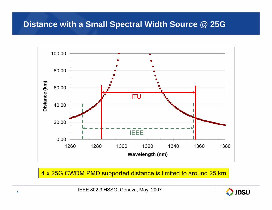
Distance with a Small Spectral Width Source @ 25G
0.00
20.00
40.00
60.00
80.00
100.00
1260 1280 1300 1320 1340 1360 1380
Wavelength (nm)
Dis
tanc
e (k
m)
IEEE
ITU
4 x 25G CWDM PMD supported distance is limited to around 25 km

10 IEEE 802.3 HSSG, Geneva, May, 2007
Proposal
Narrow grid 4 x 25G WDM around the minimum dispersion wavelength is required to support the HSSG 40km distance objective to overcomedispersion limit – Propose 200 GHz WDM grid for the transmitters
• Allow to use one EML design with temperature tuning to cover all four wavelengths, thus achieving higher laser volume for lower cost
• 400 GHz grid as an alternative is possible, but requires either larger temperature tuning range for two laser chip design
– SOA pre-Amp + PIN for the receiverEML is required to marginally support the HSSG 10km distance objective with the 4 x 25G CWDM PMD option– Propose to adopt the same WDM grid as the 40km PMD
• Increase the total volume base with the combined 10km & 40km market demand• Enable DML for the 10km distance objective for future lower cost potential • Allow to use one EML/DML design with temperature tuning to cover all four
wavelengths, thus achieving higher laser volume for lower cost– PIN for the receiver

11 IEEE 802.3 HSSG, Geneva, May, 2007
4x25G Optical Module Block Diagram --- 1st Gen
4 x 25GWDM TOSA
Optical Mux
4 x 25GWDM ROSA with TIA/AGC
Optical deMux
Laser Driver IC
CDR
4x25G to10 x 10G Gear Box
Optical Out
Optical In
ElectricalCTBI
SOAPre-Amp
Optional for 40 km

12 IEEE 802.3 HSSG, Geneva, May, 2007
4x25G Optical Module Block Diagram --- 2nd Gen
4 x 25GWDM TOSA
Optical Mux
4 x 25GWDM ROSA with TIA/AGC
Optical deMux
Laser Driver IC
CDR
Optical Out
Optical In
ElectricalCEI-25
SOAPre-Amp
Optional for 40 km

13 IEEE 802.3 HSSG, Geneva, May, 2007
Alternative Conceptual 4x25G Optical Module for 40 km
4 x 25GWDM TOSA
Optical Mux
4 x 25GWDM ROSA with TIA/AGC
Optical deMux
Laser Driver IC
CDR
Optical Out
Optical In
Electrical CEI-25
SOA

14 IEEE 802.3 HSSG, Geneva, May, 2007
25 G Transmitter Optical Assembly

15 IEEE 802.3 HSSG, Geneva, May, 2007
200 GHz Grid for WDM with Temperature Tuning

16 IEEE 802.3 HSSG, Geneva, May, 2007
25G Eye Diagrams over Temperatures
70°C 65°C
50°C 30°C

17 IEEE 802.3 HSSG, Geneva, May, 2007
25G Transmissions over 10 km SMF
1m 10km

18 IEEE 802.3 HSSG, Geneva, May, 2007
Commercially Available SOA Spec from a Vendor
One SOA may cover all four wavelengths with 200 GHz WDM grid