15 LD 500 - LOMBARDINI SERVICEservice.lombardinigroup.it/documents/Manuali Officina...Jammed...
44
1 COMPILER TECO/ATI ENDORSED DATE 29.02.2004 REG. CODE 1-5302-637 MODEL N° 51078 DATE OF ISSUE 02-04 REVISION 00 15 LD 500 1 st Edition WORK SHOP MANUAL 15 LD 500, series engines, p.no. 1-5302-637
-
Upload
hoangduong -
Category
Documents
-
view
222 -
download
3
Transcript of 15 LD 500 - LOMBARDINI SERVICEservice.lombardinigroup.it/documents/Manuali Officina...Jammed...
1COMPILER TECO/ATI ENDORSEDDATE
29.02.2004
REG. CODE
1-5302-637
MODEL N°
51078
DATE OF ISSUE
02-04REVISION 00
15 LD 500
1st Edition
WORK SHOPMANUAL
15 LD 500, series engines, p.no. 1-5302-637
2COMPILER TECO/ATI ENDORSEDDATE
29.02.2004
REG. CODE
1-5302-637
MODEL N°
51078
DATE OF ISSUE
02-04REVISION 00
FOREWORD
We have done all in our power to give up to date and accurate technical information in this manual. Lombardiniengines are, however, constantly developing thus the data in this publication may be liable to modification withoutprior notice.
The information in this manual is the exclusive property of Lombardini. Neither partial nor total duplications or reprintsare therefore permitted without the express authorization of Lombardini.
The information in this manual is given on the assumption that:
1 - the persons who service Lombardini engines have been adequately trained and outfitted to safely andprofessionally carry out the necessary tasks;
2 - the persons who service Lombardini engines possess the necessary skills and special Lombardini tools to safelyand professionally carry out the necessary tasks;
3 - the persons who service Lombardini engines have read the specific information concerning the above mentionedService operations and that they have clearly understood the operations required.
GENERAL SERVICE NOTES
1 - Only use genuine Lombardini spare parts. Use of spurious spares may lead to incorrect performance and shortenthe life of the engines.
2 - The metric system is used to express all data, i.e. the dimensions are given in millimeters (mm), torque isexpressed in Newton-meters (Nm), weight in kilograms (kg), volume in liters or cubic centimeters (cc) andpressure in barometric units (bar).
3COMPILER TECO/ATI ENDORSEDDATE
29.02.2004
REG. CODE
1-5302-637
MODEL N°
51078
DATE OF ISSUE
02-04REVISION 00
WARRANTY CERTIFICATE
WARRANTY CERTIFICATE
The products manufactured by Lombardini Srl are warranted to be free from conformity defects for a period of 24months from the date of delivery to the first end user.For engines fitted to stationary equipment, working at constant load and at constant and/or slightly variable speedwithin the setting limits, the warranty covers a period up to a limit of 2000 working hours, if the above mentionedperiod (24 months) is not expired.If no hour-meter is fitted , 12 working hours per calendar day will be considered.For what concerns the parts subject to wear and deterioration (injection/feeding system, electrical system, coolingsystem, sealing parts, non-metallic pipes, belts) warranty covers a maximum limit of 2000 working hours, if theabove mentioned period (24 months) is not expired.For correct maintenance and replacement of these parts, it is necessary to follow the instructions reported in thedocumentation supplied with each engine.To ensure the engine warranty is valid, the engine installation, considering the product technical features, must becarried out by qualified personnel only.The list of the Lombardini authorized dealers is reported in the “Service” booklet, supplied with each engine.Special applications involving considerable modifications to the cooling/lubricating system (for ex.: dry oil sump),filtering system, turbo-charged models, will require special written warranty agreements.Within the above stated periods Lombardini Srl directly or through its authorized network will repair and/or replacefree of charge any own part or component that, upon examination by Lombardini or by an authorized Lombardiniagent, is found to be defective in conformity, workmanship or materials.Any other responsibility/obligation for different expenses, damages and direct/indirect losses deriving from the engineuse or from both the total or partial impossibility of use, is excluded.The repair or replacement of any component will not extend or renew the warranty period.
Lombardini warranty obligations here above described will be cancelled if:
- Lombardini engines are not correctly installed and as a consequence the correct functional parameters are notrespected and altered.
- Lombardini engines are not used according to the instructions reported in the “Use and Maintenance” bookletsupplied with each engine.
- Any seal affixed to the engine by Lombardini has been tampered with or removed.- Spare parts used are not original Lombardini.- Feeding and injection systems are damaged by unauthorized or poor quality fuel types.- Electrical system failure is due to components, connected to this system, which are not supplied or installed by
Lombardini.- Engines have been disassembled, repaired or altered by any part other than an authorized Lombardini agent.
Following expiration of the above stated warranty periods and working hours, Lombardini will have no furtherresponsibility for warranty and will consider its here above mentioned obligations for warranty complete.Any warranty request related to a non-conformity of the product must be addressed to the Lombardini Srl serviceagents.
4COMPILER TECO/ATI ENDORSEDDATE
29.02.2004
REG. CODE
1-5302-637
MODEL N°
51078
DATE OF ISSUE
02-04REVISION 00
INDEX
I TROUBLE SHOOTING __________________________________________________________ Page 7
II SAFETY AND WARNING DECALS - SAFETY INSTRUCTIONS ____________________________ " 8
III MODEL NUMBER AND IDENTIFICATION _____________________________________________ " 10
IV TECHNICAL DATA ______________________________________________________________ " 11
V CHARACTERISTICS _____________________________________________________________ " 12
VI OVERALL DIMENSIONS __________________________________________________________ " 13
VII SPECIAL TOOLS________________________________________________________________ " 14
VIII MAINTENANCE - RECOMMENDED OIL TYPE - REFILLING_______________________________ " 15
IX DISASSEMBLY OF THE ENGINE _________________________________________________ Page 17
Demounting and remounting the main bearings .......................................................................................................... 18Demounting the piston ................................................................................................................................................... 18Flywheel extraction .......................................................................................................................................................... 17Removing the cover on the timing system side ............................................................................................................. 17Removing the injection pump......................................................................................................................................... 17Removing the injector ..................................................................................................................................................... 17
X CHECKS AND OVERHAUL ______________________________________________________ Page 19
Camshaft ........................................................................................................................................................................ 23Checking the oil pump .................................................................................................................................................... 23Connecting rod ............................................................................................................................................................... 21Crankshaft ....................................................................................................................................................................... 22Cylinder ........................................................................................................................................................................... 20Fuel pump (optional) ...................................................................................................................................................... 24Head ................................................................................................................................................................................ 19Injection pump tappets and pads ................................................................................................................................... 24Lubrication circuit ............................................................................................................................................................ 22Oil retention rings ............................................................................................................................................................ 22Piston rings - Piston - Pin ............................................................................................................................................... 21Rocker arms ................................................................................................................................................................... 20Tapets and rocker arms .................................................................................................................................................. 24Valve springs ................................................................................................................................................................... 20Valves - Guides - Housings ............................................................................................................................................ 19
This manual contains pertinent information regarding the repair of LOMBARDINI air-cooled, indirect injection Diesel enginestype 15LD500: updated February 29, 2004.
5COMPILER TECO/ATI ENDORSEDDATE
29.02.2004
REG. CODE
1-5302-637
MODEL N°
51078
DATE OF ISSUE
02-04REVISION 00
INDEX
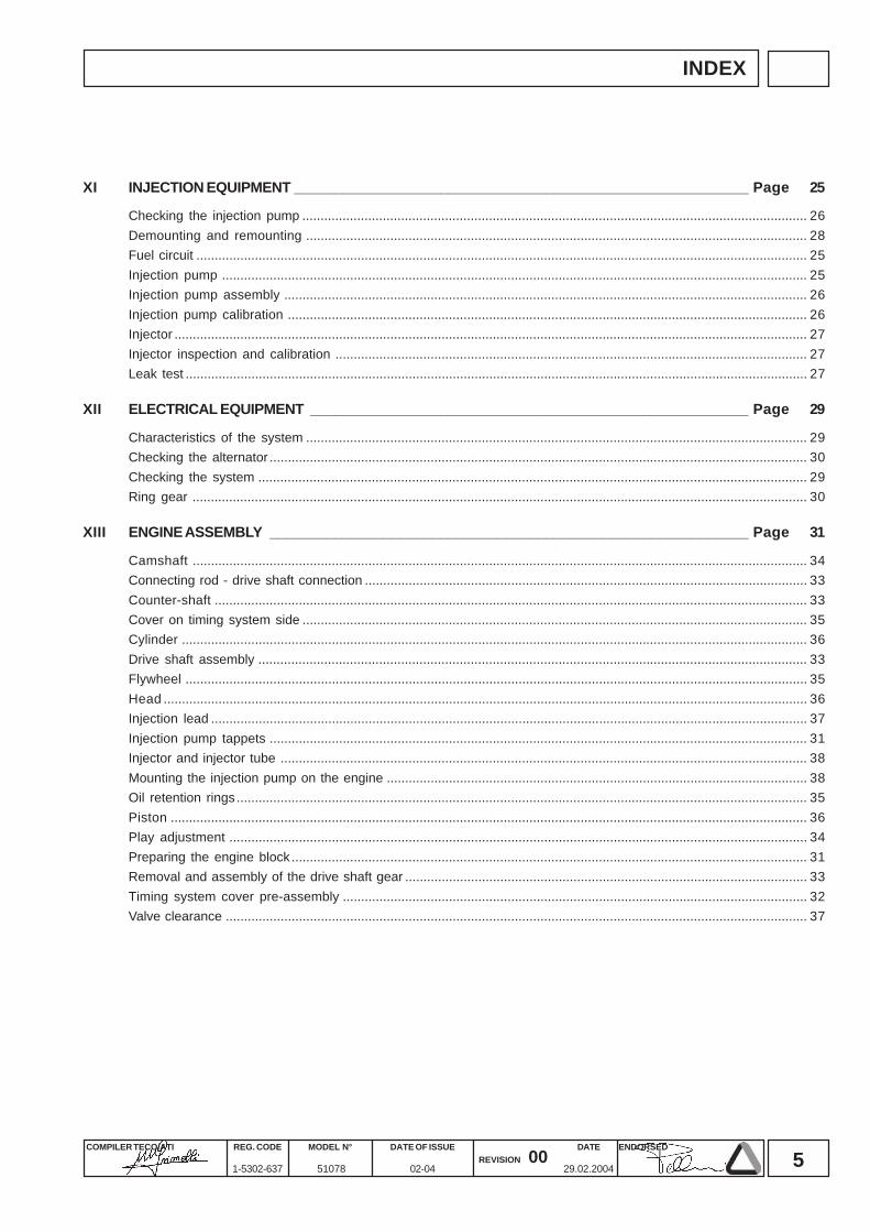
XI INJECTION EQUIPMENT ________________________________________________________ Page 25
Checking the injection pump .......................................................................................................................................... 26Demounting and remounting ......................................................................................................................................... 28Fuel circuit ....................................................................................................................................................................... 25Injection pump ................................................................................................................................................................ 25Injection pump assembly ............................................................................................................................................... 26Injection pump calibration .............................................................................................................................................. 26Injector ............................................................................................................................................................................. 27Injector inspection and calibration ................................................................................................................................. 27Leak test .......................................................................................................................................................................... 27
XII ELECTRICAL EQUIPMENT ______________________________________________________ Page 29
Characteristics of the system ......................................................................................................................................... 29Checking the alternator ................................................................................................................................................... 30Checking the system ...................................................................................................................................................... 29Ring gear ........................................................................................................................................................................ 30
XIII ENGINE ASSEMBLY ___________________________________________________________ Page 31
Camshaft ........................................................................................................................................................................ 34Connecting rod - drive shaft connection ......................................................................................................................... 33Counter-shaft .................................................................................................................................................................. 33Cover on timing system side .......................................................................................................................................... 35Cylinder ........................................................................................................................................................................... 36Drive shaft assembly ...................................................................................................................................................... 33Flywheel .......................................................................................................................................................................... 35Head ................................................................................................................................................................................ 36Injection lead ................................................................................................................................................................... 37Injection pump tappets ................................................................................................................................................... 31Injector and injector tube ................................................................................................................................................ 38Mounting the injection pump on the engine ................................................................................................................... 38Oil retention rings ............................................................................................................................................................ 35Piston .............................................................................................................................................................................. 36Play adjustment .............................................................................................................................................................. 34Preparing the engine block ............................................................................................................................................. 31Removal and assembly of the drive shaft gear .............................................................................................................. 33Timing system cover pre-assembly ............................................................................................................................... 32Valve clearance ............................................................................................................................................................... 37
6COMPILER TECO/ATI ENDORSEDDATE
29.02.2004
REG. CODE
1-5302-637
MODEL N°
51078
DATE OF ISSUE
02-04REVISION 00
INDEX
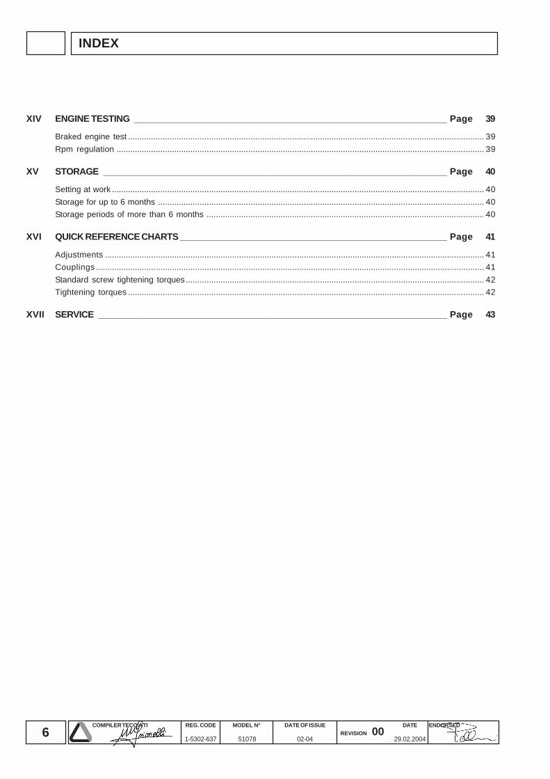
XIV ENGINE TESTING _____________________________________________________________ Page 39
Braked engine test .......................................................................................................................................................... 39Rpm regulation ............................................................................................................................................................... 39
XV STORAGE ___________________________________________________________________ Page 40
Setting at work ................................................................................................................................................................. 40Storage for up to 6 months ............................................................................................................................................. 40Storage periods of more than 6 months ........................................................................................................................ 40
XVI QUICK REFERENCE CHARTS ____________________________________________________ Page 41
Adjustments .................................................................................................................................................................... 41Couplings ........................................................................................................................................................................ 41Standard screw tightening torques ................................................................................................................................. 42Tightening torques .......................................................................................................................................................... 42
XVII SERVICE ____________________________________________________________________ Page 43
7COMPILER TECO/ATI ENDORSEDDATE
29.02.2004
REG. CODE
1-5302-637
MODEL N°
51078
DATE OF ISSUE
02-04REVISION 00
ITROUBLE SHOOTING
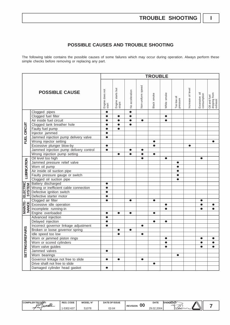
Clogged pipesClogged fuel filterAir inside fuel circuitClogged tank breather holeFaulty fuel pumpInjector jammedJammed injection pump delivery valveWrong injector settingExcessive plunger blow-byJammed injection pump delivery controlWrong injection pump settingOil level too highJammed pressure relief valveWorn oil pumpAir inside oil suction pipeFaulty pressure gauge or switchClogged oil suction pipeBattery dischargedWrong or inefficient cable connectionDefective ignition switchDefective starter motorClogged air filterExcessive idle operationIncomplete running-inEngine overloadedAdvanced injectionDelayed injectionIncorrect governor linkage adjustmentBroken or loose governor springIdle speed too lowWorn or jammed piston ringsWorn or scored cylindersWorn valve guidesJammed valvesWorn bearingsGovernor linkage not free to slideDrive shaft not free to slideDamaged cylinder head gasket
TROUBLE
LUBR
ICAT
ION
POSSIBLE CAUSE
FUEL
CIR
CUIT
ELEC
TRIC
SYST
EMM
AINT
E-NA
NCE
SETT
ING
S/RE
PAIR
S
POSSIBLE CAUSES AND TROUBLE SHOOTING
The following table contains the possible causes of some failures which may occur during operation. Always perform thesesimple checks before removing or replacing any part.
Engi
ne d
oes
not
star
t
No
acce
lera
tion
Blac
k sm
oke
Exce
ssiv
e oi
lco
nsum
ptio
n
Too
low
oil
pres
sure
Engi
ne s
tarts
but
stop
s
Non
-uni
form
spe
ed
Whi
te s
mok
e
Oil
and
fuel
drip
ping
from
exha
ust
Incr
ease
oil
leve
l
8COMPILER TECO/ATI ENDORSEDDATE
29.02.2004
REG. CODE
1-5302-637
MODEL N°
51078
DATE OF ISSUE
02-04REVISION 00
II SAFETY AND WARNING DECALS - SAFETY INSTRUCTIONS
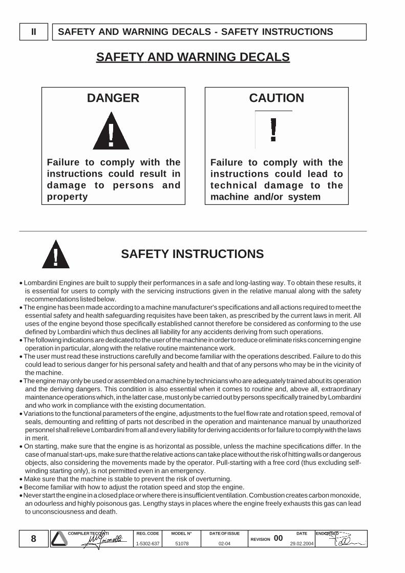
Failure to comply with theinstructions could result indamage to persons andproperty
Failure to comply with theinstructions could lead totechnical damage to themachine and/or system
SAFETY AND WARNING DECALS
SAFETY INSTRUCTIONS
DANGER CAUTION
• Lombardini Engines are built to supply their performances in a safe and long-lasting way. To obtain these results, itis essential for users to comply with the servicing instructions given in the relative manual along with the safetyrecommendations listed below.
• The engine has been made according to a machine manufacturer's specifications and all actions required to meet theessential safety and health safeguarding requisites have been taken, as prescribed by the current laws in merit. Alluses of the engine beyond those specifically established cannot therefore be considered as conforming to the usedefined by Lombardini which thus declines all liability for any accidents deriving from such operations.
• The following indications are dedicated to the user of the machine in order to reduce or eliminate risks concerning engineoperation in particular, along with the relative routine maintenance work.
• The user must read these instructions carefully and become familiar with the operations described. Failure to do thiscould lead to serious danger for his personal safety and health and that of any persons who may be in the vicinity ofthe machine.
• The engine may only be used or assembled on a machine by technicians who are adequately trained about its operationand the deriving dangers. This condition is also essential when it comes to routine and, above all, extraordinarymaintenance operations which, in the latter case, must only be carried out by persons specifically trained by Lombardiniand who work in compliance with the existing documentation.
• Variations to the functional parameters of the engine, adjustments to the fuel flow rate and rotation speed, removal ofseals, demounting and refitting of parts not described in the operation and maintenance manual by unauthorizedpersonnel shall relieve Lombardini from all and every liability for deriving accidents or for failure to comply with the lawsin merit.
• On starting, make sure that the engine is as horizontal as possible, unless the machine specifications differ. In thecase of manual start-ups, make sure that the relative actions can take place without the risk of hitting walls or dangerousobjects, also considering the movements made by the operator. Pull-starting with a free cord (thus excluding self-winding starting only), is not permitted even in an emergency.
• Make sure that the machine is stable to prevent the risk of overturning.• Become familiar with how to adjust the rotation speed and stop the engine.• Never start the engine in a closed place or where there is insufficient ventilation. Combustion creates carbon monoxide,
an odourless and highly poisonous gas. Lengthy stays in places where the engine freely exhausts this gas can leadto unconsciousness and death.
9COMPILER TECO/ATI ENDORSEDDATE
29.02.2004
REG. CODE
1-5302-637
MODEL N°
51078
DATE OF ISSUE
02-04REVISION 00
IISAFETY AND WARNING DECALS - SAFETY INSTRUCTIONS
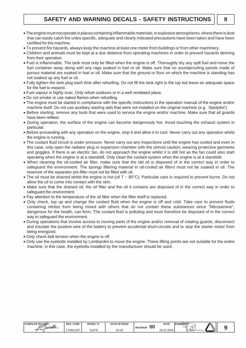
• The engine must not operate in places containing inflammable materials, in explosive atmospheres, where there is dustthat can easily catch fire unles specific, adequate and clearly indicated precautions have been taken and have beencertified for the machine.
• To prevent fire hazards, always keep the machine at least one meter from buildings or from other machinery.• Children and animals must be kept at a due distance from operating machines in order to prevent hazards deriving
from their operation.• Fuel is inflammable. The tank must only be filled when the engine is off. Thoroughly dry any spilt fuel and move the
fuel container away along with any rags soaked in fuel or oil. Make sure that no soundproofing panels made ofporous material are soaked in fuel or oil. Make sure that the ground or floor on which the machine is standing hasnot soaked up any fuel or oil.
• Fully tighten the tank plug each time after refuelling. Do not fill the tank right to the top but leave an adequate spacefor the fuel to expand.
• Fuel vapour is highly toxic. Only refuel outdoors or in a well ventilated place.• Do not smoke or use naked flames when refuelling.• The engine must be started in compliance with the specific instructions in the operation manual of the engine and/or
machine itself. Do not use auxiliary starting aids that were not installed on the original machine (e.g. Startpilot’).• Before starting, remove any tools that were used to service the engine and/or machine. Make sure that all guards
have been refitted.• During operation, the surface of the engine can become dangerously hot. Avoid touching the exhaust system in
particular.• Before proceeding with any operation on the engine, stop it and allow it to cool. Never carry out any operation whilst
the engine is running.• The coolant fluid circuit is under pressure. Never carry out any inspections until the engine has cooled and even in
this case, only open the radiator plug or expansion chamber with the utmost caution, wearing protective garmentsand goggles. If there is an electric fan, do not approach the engine whilst it is still hot as the fan could also startoperating when the engine is at a standstill. Only clean the coolant system when the engine is at a standstill.
• When cleaning the oil-cooled air filter, make sure that the old oil is disposed of in the correct way in order tosafeguard the environment. The spongy filtering material in oil-cooled air filters must not be soaked in oil. Thereservoir of the separator pre-filter must not be filled with oil.
• The oil must be drained whilst the engine is hot (oil T ~ 80°C). Particular care is required to prevent burns. Do notallow the oil to come into contact with the skin.
• Make sure that the drained oil, the oil filter and the oil it contains are disposed of in the correct way in order tosafeguard the environment.
• Pay attention to the temperature of the oil filter when the filter itself is replaced.• Only check, top up and change the coolant fluid when the engine is off and cold. Take care to prevent fluids
containing nitrites from being mixed with others that do not contain these substances since "Nitrosamine",dangerous for the health, can form. The coolant fluid is polluting and must therefore be disposed of in the correctway to safeguard the environment.
• During operations that involve access to moving parts of the engine and/or removal of rotating guards, disconnectand insulate the positive wire of the battery to prevent accidental short-circuits and to stop the starter motor frombeing energized.
• Only check belt tension when the engine is off.• Only use the eyebolts installed by Lombardini to move the engine. These lifting points are not suitable for the entire
machine; in this case, the eyebolts installed by the manufacturer should be used.
10COMPILER TECO/ATI ENDORSEDDATE
29.02.2004
REG. CODE
1-5302-637
MODEL N°
51078
DATE OF ISSUE
02-04REVISION 00
III MODEL NUMBER AND IDENTIFICATION
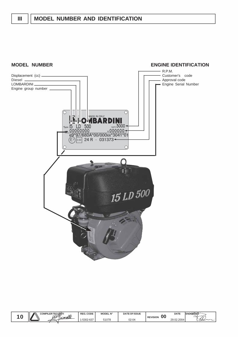
ENGINE IDENTIFICATIONR.P.M.Customer's codeApproval codeEngine Serial Number
MODEL NUMBER
Displacement (cc)DieselLOMBARDINIEngine group number
11COMPILER TECO/ATI ENDORSEDDATE
29.02.2004
REG. CODE
1-5302-637
MODEL N°
51078
DATE OF ISSUE
02-04REVISION 00
IV
15 LD 500
TECHNICAL DATA
CHARACTERISTICS
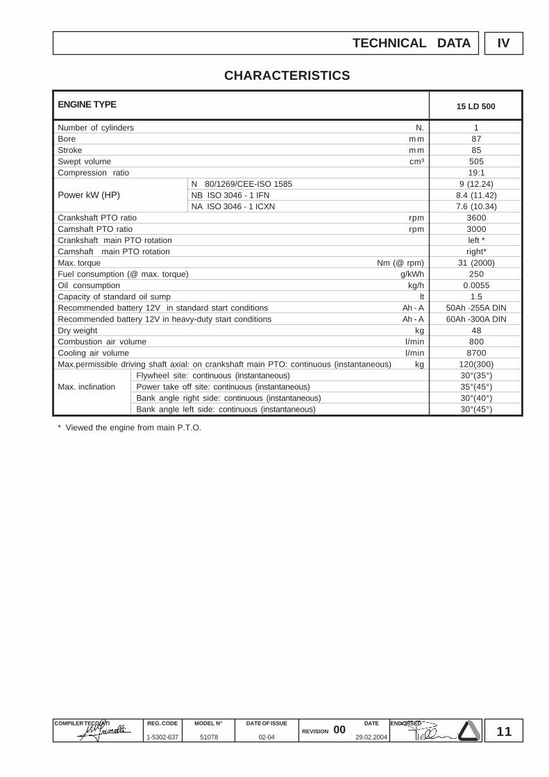
ENGINE TYPE
Number of cylinders N. 1Bore m m 87Stroke m m 85Swept volume cm³ 505Compression ratio 19:1
N 80/1269/CEE-ISO 1585 9 (12.24)Power kW (HP) NB ISO 3046 - 1 IFN 8.4 (11.42)
NA ISO 3046 - 1 ICXN 7.6 (10.34)Crankshaft PTO ratio rpm 3600Camshaft PTO ratio rpm 3000Crankshaft main PTO rotation left *Camshaft main PTO rotation right*Max. torque Nm (@ rpm) 31 (2000)Fuel consumption (@ max. torque) g/kWh 250Oil consumption kg/h 0.0055Capacity of standard oil sump lt 1.5Recommended battery 12V in standard start conditions Ah - A 50Ah -255A DINRecommended battery 12V in heavy-duty start conditions Ah - A 60Ah -300A DINDry weight kg 48Combustion air volume l/min 800Cooling air volume l/min 8700Max.permissible driving shaft axial: on crankshaft main PTO: continuous (instantaneous) kg 120(300)
Flywheel site: continuous (instantaneous) 30°(35°)Max. inclination Power take off site: continuous (instantaneous) 35°(45°)
Bank angle right side: continuous (instantaneous) 30°(40°)Bank angle left side: continuous (instantaneous) 30°(45°)
* Viewed the engine from main P.T.O.
12COMPILER TECO/ATI ENDORSEDDATE
29.02.2004
REG. CODE
1-5302-637
MODEL N°
51078
DATE OF ISSUE
02-04REVISION 00
V
15 LD 500
CHARACTERISTICS
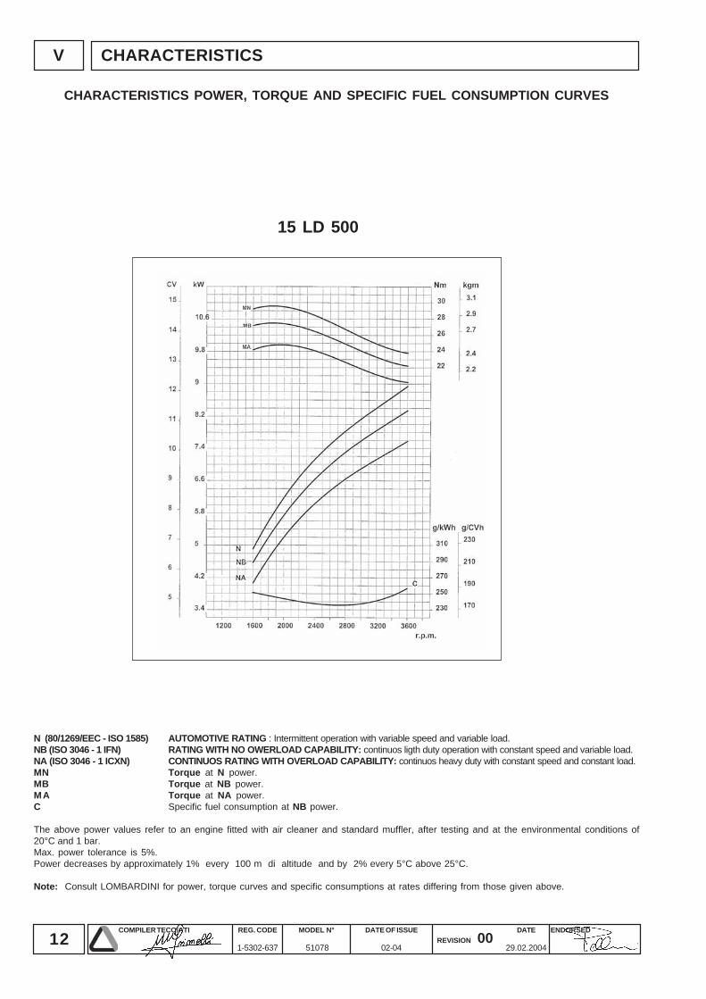
CHARACTERISTICS POWER, TORQUE AND SPECIFIC FUEL CONSUMPTION CURVES
N (80/1269/EEC - ISO 1585) AUTOMOTIVE RATING : Intermittent operation with variable speed and variable load.NB (ISO 3046 - 1 IFN) RATING WITH NO OWERLOAD CAPABILITY: continuos ligth duty operation with constant speed and variable load.NA (ISO 3046 - 1 ICXN) CONTINUOS RATING WITH OVERLOAD CAPABILITY: continuos heavy duty with constant speed and constant load.MN Torque at N power.MB Torque at NB power.MA Torque at NA power.C Specific fuel consumption at NB power.
The above power values refer to an engine fitted with air cleaner and standard muffler, after testing and at the environmental conditions of20°C and 1 bar.Max. power tolerance is 5%.Power decreases by approximately 1% every 100 m di altitude and by 2% every 5°C above 25°C.
Note: Consult LOMBARDINI for power, torque curves and specific consumptions at rates differing from those given above.
13COMPILER TECO/ATI ENDORSEDDATE
29.02.2004
REG. CODE
1-5302-637
MODEL N°
51078
DATE OF ISSUE
02-04REVISION 00
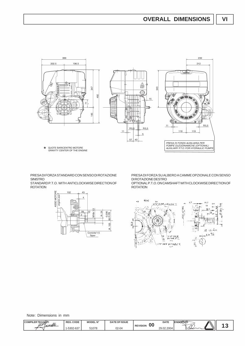
VI
PRESA DI FORZA SU ALBERO A CAMME OPZIONALE CON SENSODI ROTAZIONE DESTROOPTIONAL P.T.O. ON CAMSHAFT WITH CLOCKWISE DIRECTION OFROTATION
PRESA DI FORZA STANDARD CON SENSO DI ROTAZIONESINISTROSTANDARD P.T.O. WITH ANTICLOCKWISE DIRECTION OFROTATION
OVERALL DIMENSIONS
Note: Dimensions in mm
14COMPILER TECO/ATI ENDORSEDDATE
29.02.2004
REG. CODE
1-5302-637
MODEL N°
51078
DATE OF ISSUE
02-04REVISION 00
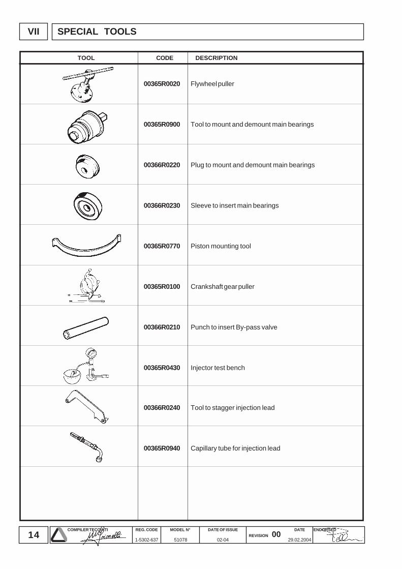
VII
00365R0020
00365R0900
00366R0220
00366R0230
00365R0770
00365R0100
00366R0210
00365R0430
00366R0240
00365R0940
SPECIAL TOOLS
TOOL CODE DESCRIPTION
Flywheel puller
Tool to mount and demount main bearings
Plug to mount and demount main bearings
Sleeve to insert main bearings
Piston mounting tool
Crankshaft gear puller
Punch to insert By-pass valve
Injector test bench
Tool to stagger injection lead
Capillary tube for injection lead
15COMPILER TECO/ATI ENDORSEDDATE
29.02.2004
REG. CODE
1-5302-637
MODEL N°
51078
DATE OF ISSUE
02-04REVISION 00
VIII
10 50(1) 250(2) 500(3) 2500 5000
•••
••
••••••
••
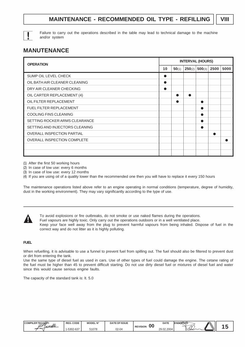
MAINTENANCE - RECOMMENDED OIL TYPE - REFILLING
Failure to carry out the operations described in the table may lead to technical damage to the machineand/or system
To avoid explosions or fire outbreaks, do not smoke or use naked flames during the operations.Fuel vapours are highly toxic. Only carry out the operations outdoors or in a well ventilated place.Keep your face well away from the plug to prevent harmful vapours from being inhaled. Dispose of fuel in thecorrect way and do not litter as it is highly polluting.
FUEL
When refuelling, it is advisable to use a funnel to prevent fuel from spilling out. The fuel should also be filtered to prevent dustor dirt from entering the tank.Use the same type of diesel fuel as used in cars. Use of other types of fuel could damage the engine. The cetane rating ofthe fuel must be higher than 45 to prevent difficult starting. Do not use dirty diesel fuel or mixtures of diesel fuel and watersince this would cause serious engine faults.
The capacity of the standard tank is: lt. 5.0
The maintenance operations listed above refer to an engine operating in normal conditions (temperature, degree of humidity,dust in the working environment). They may vary significantly according to the type of use.
MANUTENANCEINTERVAL (HOURS)
OPERATION
SUMP OIL LEVEL CHECK
OIL BATH AIR CLEANER CLEANING
DRY AIR CLEANER CHECKING
OIL CARTER REPLACEMENT (4)
OIL FILTER REPLACEMENT
FUEL FILTER REPLACEMENT
COOLING FINS CLEANING
SETTING ROCKER ARMS CLEARANCE
SETTING AND INJECTORS CLEANING
OVERALL INSPECTION PARTIAL
OVERALL INSPECTION COMPLETE
(1) After the first 50 working hours(2) In case of low use: every 6 months(3) In case of low use: every 12 months(4) If you are using oil of a quality lower than the recommended one then you will have to replace it every 150 hours
16COMPILER TECO/ATI ENDORSEDDATE
29.02.2004
REG. CODE
1-5302-637
MODEL N°
51078
DATE OF ISSUE
02-04REVISION 00
VIII
-30
-25
-20
-15
-10
-5 0
+5
+10
+15
+20
+25
+30
+35
+40
+45
SAE 20WSAE 10W
+50
SAE 30SAE 40
SAE 10W-30SAE 10W-40
SAE 10W-60SAE 15W-40 base minerale
SAE 15W-40 base semi-sintetica
SAE 20W-60 base semi-sinteticaSAE 5W-30 base sintetica
SAE 0W-30 base sinteticaSAE 5W-40 base sintetica
-35
-40
CCMC G- 2CF CE CD CC CB CA SA SB SC SD SE SF SG
DIESEL BENZINA - ESSENCE - PETROLBENZIN - GASOLINA
CCMC G- 3 G- 5CCMC PD - 1 / PD - 2
CCMC D- 2D- 4CCMC D- 3D- 5
MIL - L - 2104 DMIL - L - 2104 E
MIL - L -46152 CMIL - L- 46152 D/E
MB 226.1 MB 226.5MB 227.1 MB 227.5
228.3 MB 228.1
VW 501.01VW 500.00
SHAPIG- 4
SJ
VOLVO VDSMAN QC 13-017
VW 505.00
MAINTENANCE - RECOMMENDED OIL TYPE - REFILLING
The engine could be damaged if allowed to operate with insufficient oil. It is also dangerous to add too much oil asits combustion could sharply increase the rotation speed.Use a suitable oil in order to protect the engine.The lubrication oil influences the performances and life of the engine in an incredible way.The risk of piston seizure, jammed piston rings and rapid wear of the cylinder liner, the bearings and all movingparts increases if oil whose characteristics differ from the recommended type is used, or if the oil is not regularlychanged. All this notably reduces engine life.Oil viscosity must suit the ambient temperature in which the engine operates.
Old oil can cause skin cancer if repeatedly left in contact with the skin and for long periods of time. If contact with theoil is inevitable, you are advised to thoroughly wash your hands with soap and water as soon as possible.Appropriate protective gloves etc should be wore during this operation.Old oil is highly polluting and must be disposed of in the correct way. Do not litter.
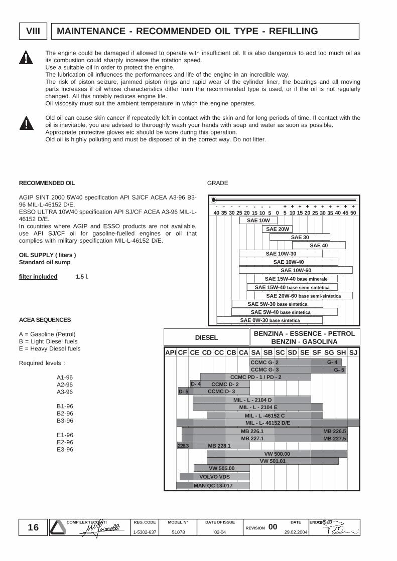
GRADERECOMMENDED OIL
AGIP SINT 2000 5W40 specification API SJ/CF ACEA A3-96 B3-96 MIL-L-46152 D/E.ESSO ULTRA 10W40 specification API SJ/CF ACEA A3-96 MIL-L-46152 D/E.In countries where AGIP and ESSO products are not available,use API SJ/CF oil for gasoline-fuelled engines or oil thatcomplies with military specification MIL-L-46152 D/E.
OIL SUPPLY ( liters )Standard oil sump
filter included 1.5 l.
ACEA SEQUENCES
A = Gasoline (Petrol)B = Light Diesel fuelsE = Heavy Diesel fuels
Required levels :
A1-96A2-96A3-96
B1-96B2-96B3-96
E1-96E2-96E3-96
17COMPILER TECO/ATI ENDORSEDDATE
29.02.2004
REG. CODE
1-5302-637
MODEL N°
51078
DATE OF ISSUE
02-04REVISION 00
IX
1
2
3
4
DISASSEMBLY OF THE ENGINE
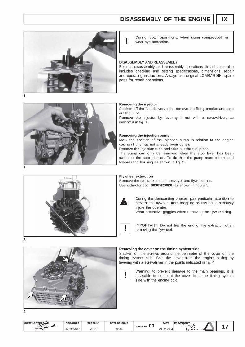
During repair operations, when using compressed air,wear eye protection.
Flywheel extractionRemove the fuel tank, the air conveyor and flywheel nut.Use extractor cod. 00365R0020, as shown in figure 3.
During the demounting phases, pay particular attention toprevent the flywheel from dropping as this could seriouslyinjure the operator.Wear protective goggles when removing the flywheel ring.
IMPORTANT: Do not tap the end of the extractor whenremoving the flywheel.
Removing the injectorSlacken off the fuel delivery pipe, remove the fixing bracket and takeout the tube.Remove the injector by levering it out with a screwdriver, asindicated in fig. 1.
Removing the injection pumpMark the position of the injection pump in relation to the enginecasing (if this has not already been done).Remove the injection tube and take out the fuel pipes.The pump can only be removed when the stop lever has beenturned to the stop position. To do this, the pump must be pressedtowards the housing as shown in fig. 2.
Removing the cover on the timing system sideSlacken off the screws around the perimeter of the cover on thetiming system side. Split the cover from the engine casing bylevering with a screwdriver in the points indicated in fig. 4.
Warning: to prevent damage to the main bearings, it isadvisable to demount the cover from the timing systemside with the engine cold.
DISASSEMBLY AND REASSEMBLYBesides disassembly and reassembly operations this chapter alsoincludes checking and setting specifications, dimensions, repairand operating instructions. Always use original LOMBARDINI spareparts for repair operations.
18COMPILER TECO/ATI ENDORSEDDATE
29.02.2004
REG. CODE
1-5302-637
MODEL N°
51078
DATE OF ISSUE
02-04REVISION 00
IX
5
6
7
00365R0900
00366R0220
00366R023000366R0220
00365R0900
DISASSEMBLY OF THE ENGINE
Main bearing
Main bearing
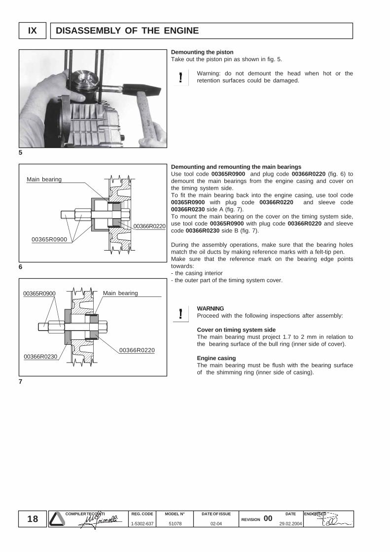
Demounting the pistonTake out the piston pin as shown in fig. 5.
Warning: do not demount the head when hot or theretention surfaces could be damaged.
Demounting and remounting the main bearingsUse tool code 00365R0900 and plug code 00366R0220 (fig. 6) todemount the main bearings from the engine casing and cover onthe timing system side.To fit the main bearing back into the engine casing, use tool code00365R0900 with plug code 00366R0220 and sleeve code00366R0230 side A (fig. 7).To mount the main bearing on the cover on the timing system side,use tool code 00365R0900 with plug code 00366R0220 and sleevecode 00366R0230 side B (fig. 7).
During the assembly operations, make sure that the bearing holesmatch the oil ducts by making reference marks with a felt-tip pen.Make sure that the reference mark on the bearing edge pointstowards:- the casing interior- the outer part of the timing system cover.
WARNINGProceed with the following inspections after assembly:
Cover on timing system sideThe main bearing must project 1.7 to 2 mm in relation tothe bearing surface of the bull ring (inner side of cover).
Engine casingThe main bearing must be flush with the bearing surfaceof the shimming ring (inner side of casing).
19COMPILER TECO/ATI ENDORSEDDATE
29.02.2004
REG. CODE
1-5302-637
MODEL N°
51078
DATE OF ISSUE
02-04REVISION 00
8
9
10
11
X
B B
C1 C2
A
D1 D2
G
F1
F2
A
E E
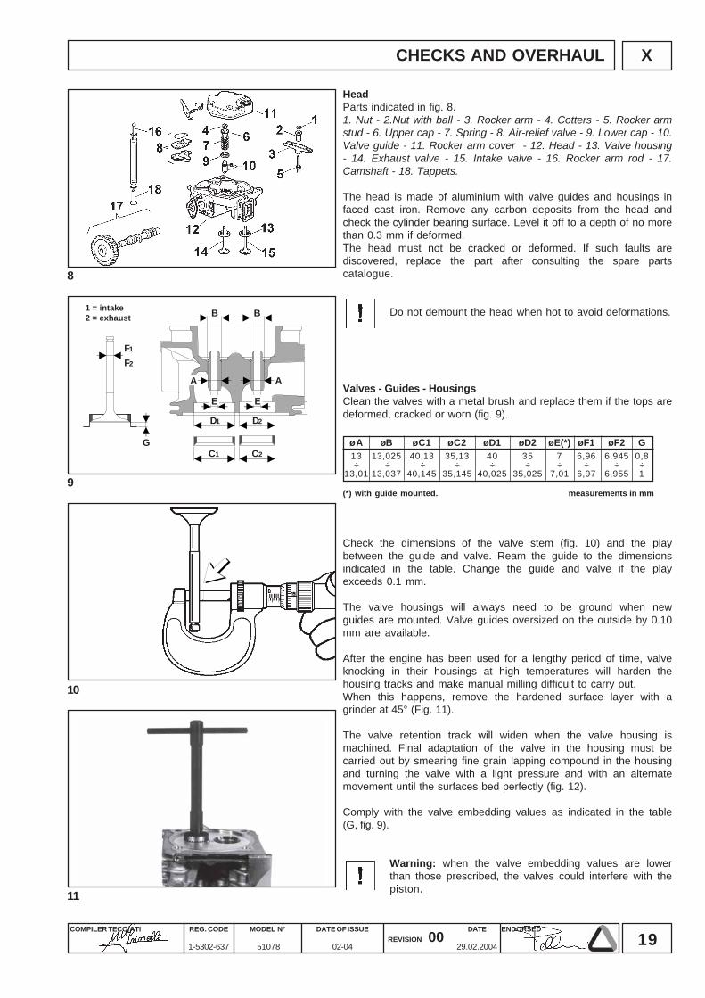
øA øB øC1 øC2 øD1 øD2 øE(*) øF1 øF2 G13 13,025 40,13 35,13 40 35 7 6,96 6,945 0,8÷ ÷ ÷ ÷ ÷ ÷ ÷ ÷ ÷ ÷
13,01 13,037 40,145 35,145 40,025 35,025 7,01 6,97 6,955 1
CHECKS AND OVERHAUL
HeadParts indicated in fig. 8.1. Nut - 2.Nut with ball - 3. Rocker arm - 4. Cotters - 5. Rocker armstud - 6. Upper cap - 7. Spring - 8. Air-relief valve - 9. Lower cap - 10.Valve guide - 11. Rocker arm cover - 12. Head - 13. Valve housing- 14. Exhaust valve - 15. Intake valve - 16. Rocker arm rod - 17.Camshaft - 18. Tappets.
The head is made of aluminium with valve guides and housings infaced cast iron. Remove any carbon deposits from the head andcheck the cylinder bearing surface. Level it off to a depth of no morethan 0.3 mm if deformed.The head must not be cracked or deformed. If such faults arediscovered, replace the part after consulting the spare partscatalogue.
Do not demount the head when hot to avoid deformations.
Valves - Guides - HousingsClean the valves with a metal brush and replace them if the tops aredeformed, cracked or worn (fig. 9).
(*) with guide mounted. measurements in mm
Check the dimensions of the valve stem (fig. 10) and the playbetween the guide and valve. Ream the guide to the dimensionsindicated in the table. Change the guide and valve if the playexceeds 0.1 mm.
The valve housings will always need to be ground when newguides are mounted. Valve guides oversized on the outside by 0.10mm are available.
After the engine has been used for a lengthy period of time, valveknocking in their housings at high temperatures will harden thehousing tracks and make manual milling difficult to carry out.When this happens, remove the hardened surface layer with agrinder at 45° (Fig. 11).
The valve retention track will widen when the valve housing ismachined. Final adaptation of the valve in the housing must becarried out by smearing fine grain lapping compound in the housingand turning the valve with a light pressure and with an alternatemovement until the surfaces bed perfectly (fig. 12).
Comply with the valve embedding values as indicated in the table(G, fig. 9).
Warning: when the valve embedding values are lowerthan those prescribed, the valves could interfere with thepiston.
1 = intake2 = exhaust
20COMPILER TECO/ATI ENDORSEDDATE
29.02.2004
REG. CODE
1-5302-637
MODEL N°
51078
DATE OF ISSUE
02-04REVISION 00
X
12
13
14
15
42.3
÷ 4
3.7
28.3
÷ 2
8,5
18,7
÷ 1
8,9
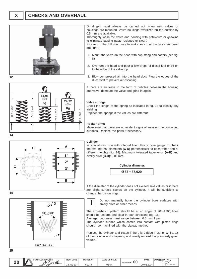
14,91±5%Kg
D
C A
2°1°
3°
B
X
90° - 120°
Ra = 0,5 - 1 µ
24,72±5%Kg
Ø 87 ÷ 87,020
CHECKS AND OVERHAUL
Free
len
gth
Grinding-in must always be carried out when new valves orhousings are mounted. Valve housings oversized on the outside by0.5 mm are available.Thoroughly wash the valve and housing with petroleum or gasolineto eliminate lapping paste residues or swarf.Proceed in the following way to make sure that the valve and seatare tight:
1. Mount the valve on the head with cap string and cotters (see fig.8)
2. Overturn the head and pour a few drops of diesel fuel or oil onto the edge of the valve top
3. Blow compressed air into the head duct. Plug the edges of theduct itself to prevent air escaping.
If there are air leaks in the form of bubbles between the housingand valve, demount the valve and grind-in again.
Valve springsCheck the length of the spring as indicated in fig. 13 to identify anyyielding.Replace the springs if the values are different.
Rocker armsMake sure that there are no evident signs of wear on the contactingsurfaces. Replace the parts if necessary.
CylinderIn special cast iron with integral liner. Use a bore gauge to checkthe two internal diameters (C-D) perpendicular to each other and atdifferent heights (fig. 14). Maximum tolerated taper error (A-B) andovality error (C-D): 0.06 mm.
Cylinder diameter:
If the diameter of the cylinder does not exceed said values or if thereare slight surface scores on the cylinder, it will be sufficient tochange the piston rings.
Do not manually hone the cylinder bore surfaces withemery cloth or other means.
The cross-hatch pattern should be at an angle of 90°÷120°; linesshould be uniform and clear in both directions (fig. 15).Average roughness must range between 0.5 mm 1 µm.The cylinder surface which comes into contact with piston ringsshould be machined with the plateau method.
Replace the cylinder and piston if there is a ridge in zone "X" fig. 15of the cylinder and if tapering and ovality exceed the previously givenvalues.
21COMPILER TECO/ATI ENDORSEDDATE
29.02.2004
REG. CODE
1-5302-637
MODEL N°
51078
DATE OF ISSUE
02-04REVISION 00
X
16
17
18
19
A
B
C
100 m m
-0,02+0,02-0,020
+0,020
+ - + -
0,30 ÷ 0,50
0,25 ÷ 0,50
0,80
0,80
A = 0,22
B = 0,19
C = 0,16
Ø 86,915 ÷ 86,835
0,003 ÷ 0,013 0,04021,997 ÷ 22,002
0,023 ÷ 0,038 0,07021,997 ÷ 22,002
CHECKS AND OVERHAUL
Fitting mm Max. wear mm
Piston ring
1st Compression
2nd Compression
3rd Oil scrapper
Max. wear mm
Piston ring
Compression
Oil scrapper
Assy.clearance mm Max. wear mm Pin Ø mm
Assy.clearance mm Max. wear mm Pin Ø mm
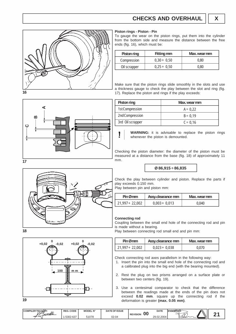
Piston rings - Piston - PinTo gauge the wear on the piston rings, put them into the cylinderfrom the bottom side and measure the distance between the freeends (fig. 16), which must be:
Make sure that the piston rings slide smoothly in the slots and usea thickness gauge to check the play between the slot and ring (fig.17). Replace the piston and rings if the play exceeds:
WARNING: it is advisable to replace the piston ringswhenever the piston is demounted.
Checking the piston diameter: the diameter of the piston must bemeasured at a distance from the base (fig. 18) of approximately 11mm.
Connecting rodCoupling between the small end hole of the connecting rod and pinis made without a bearing.Play between connecting rod small end and pin mm:
Check connecting rod axes parallelism in the following way:1. Insert the pin into the small end hole of the connecting rod and
a calibrated plug into the big end (with the bearing mounted).
2. Rest the plug on two prisms arranged on a surface plate orbetween two centers (fig. 19).
3. Use a centesimal comparator to check that the differencebetween the readings made at the ends of the pin does notexceed 0.02 mm. square up the connecting rod if thedeformation is greater (max. 0.05 mm).
Check the play between cylinder and piston. Replace the parts ifplay exceeds 0.150 mm.Play between pin and piston mm:
22COMPILER TECO/ATI ENDORSEDDATE
29.02.2004
REG. CODE
1-5302-637
MODEL N°
51078
DATE OF ISSUE
02-04REVISION 00
X
20
21
22
23
5
CA
B
R 1 R 0,5
R 3
3
2
1
4
76
6
A C
B
-0,25 mm
41,72 ÷ 41,74
39,73 ÷ 39,75
STD mm
41,97 ÷ 41,99
39,98 ÷ 40
CHECKS AND OVERHAUL
Dimensions
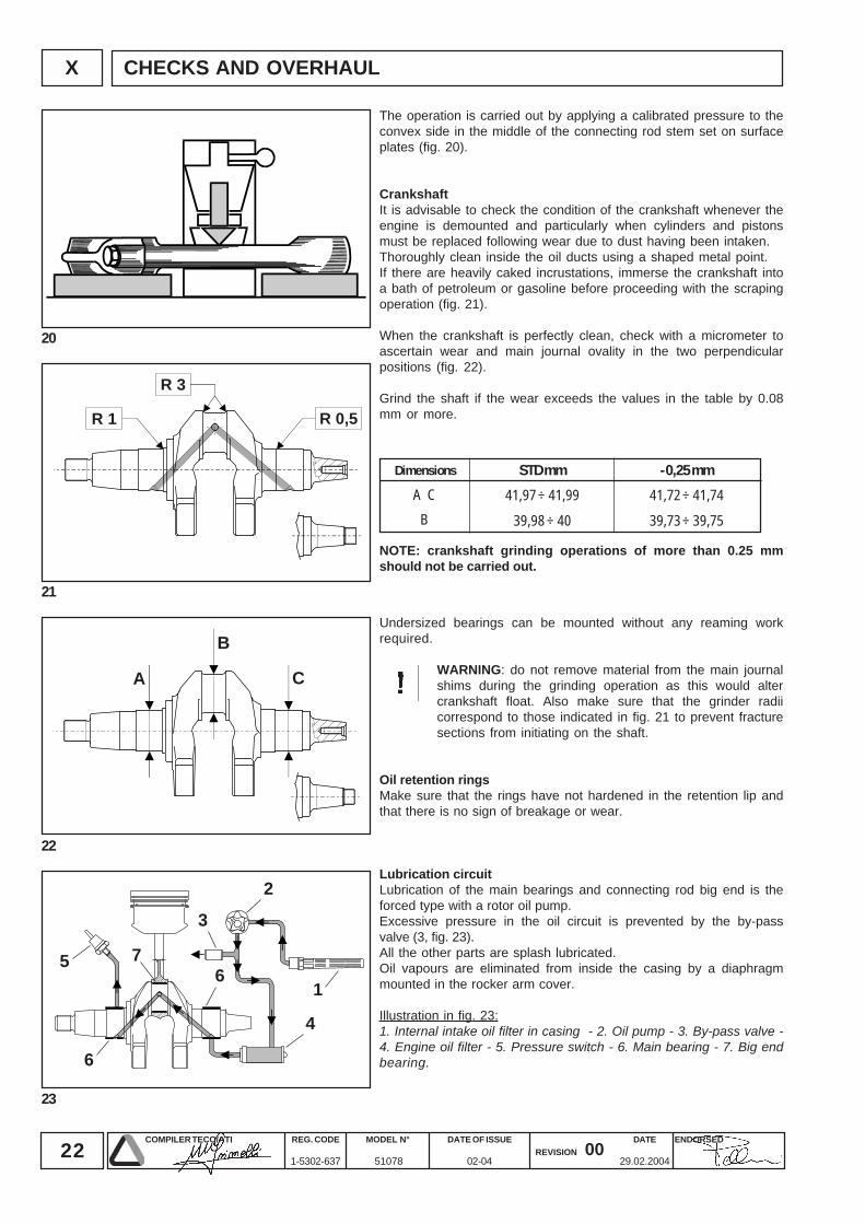
The operation is carried out by applying a calibrated pressure to theconvex side in the middle of the connecting rod stem set on surfaceplates (fig. 20).
CrankshaftIt is advisable to check the condition of the crankshaft whenever theengine is demounted and particularly when cylinders and pistonsmust be replaced following wear due to dust having been intaken.Thoroughly clean inside the oil ducts using a shaped metal point.If there are heavily caked incrustations, immerse the crankshaft intoa bath of petroleum or gasoline before proceeding with the scrapingoperation (fig. 21).
When the crankshaft is perfectly clean, check with a micrometer toascertain wear and main journal ovality in the two perpendicularpositions (fig. 22).
Grind the shaft if the wear exceeds the values in the table by 0.08mm or more.
Undersized bearings can be mounted without any reaming workrequired.
WARNING: do not remove material from the main journalshims during the grinding operation as this would altercrankshaft float. Also make sure that the grinder radiicorrespond to those indicated in fig. 21 to prevent fracturesections from initiating on the shaft.
Oil retention ringsMake sure that the rings have not hardened in the retention lip andthat there is no sign of breakage or wear.
Lubrication circuitLubrication of the main bearings and connecting rod big end is theforced type with a rotor oil pump.Excessive pressure in the oil circuit is prevented by the by-passvalve (3, fig. 23).All the other parts are splash lubricated.Oil vapours are eliminated from inside the casing by a diaphragmmounted in the rocker arm cover.
Illustration in fig. 23:1. Internal intake oil filter in casing - 2. Oil pump - 3. By-pass valve -4. Engine oil filter - 5. Pressure switch - 6. Main bearing - 7. Big endbearing.
NOTE: crankshaft grinding operations of more than 0.25 mmshould not be carried out.
23COMPILER TECO/ATI ENDORSEDDATE
29.02.2004
REG. CODE
1-5302-637
MODEL N°
51078
DATE OF ISSUE
02-04REVISION 00
X
24
25
26
27
FEC
F DØ
17,9
73 ÷
17,
984
DD
Ø17
,973
÷ 1
7,98
4
40,8
5 ÷
40,9
0
35,9
5 ÷
36,0
0
0,16 ÷ 0,215 0,345
C
D
E
F
Ø 25,97 ÷ 25,99
Ø 34,96 ÷ 34,99
26,205 ÷ 26,27
7,97 ÷ 7,99
Ø 25,92
Ø 34,87
26,31
7,93
0,03 ÷ 0,07 0,11
CHECKS AND OVERHAUL
Fitting mm Max. wear mm
Measurement Max. wear mmDimensions mm
Fitting mm Max. wear mm
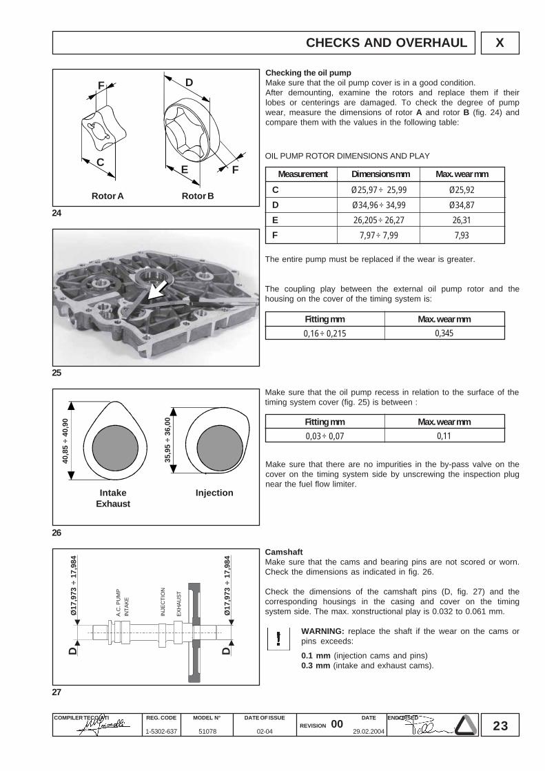
Checking the oil pumpMake sure that the oil pump cover is in a good condition.After demounting, examine the rotors and replace them if theirlobes or centerings are damaged. To check the degree of pumpwear, measure the dimensions of rotor A and rotor B (fig. 24) andcompare them with the values in the following table:
OIL PUMP ROTOR DIMENSIONS AND PLAY
The entire pump must be replaced if the wear is greater.
The coupling play between the external oil pump rotor and thehousing on the cover of the timing system is:
Make sure that the oil pump recess in relation to the surface of thetiming system cover (fig. 25) is between :
Make sure that there are no impurities in the by-pass valve on thecover on the timing system side by unscrewing the inspection plugnear the fuel flow limiter.
CamshaftMake sure that the cams and bearing pins are not scored or worn.Check the dimensions as indicated in fig. 26.
Check the dimensions of the camshaft pins (D, fig. 27) and thecorresponding housings in the casing and cover on the timingsystem side. The max. xonstructional play is 0.032 to 0.061 mm.
WARNING: replace the shaft if the wear on the cams orpins exceeds:
0.1 mm (injection cams and pins)0.3 mm (intake and exhaust cams).
InjectionIntakeExhaust
Rotor A Rotor B
A.C
. PU
MP
INTA
KE
INJE
CTI
ON
EXH
AUST
24COMPILER TECO/ATI ENDORSEDDATE
29.02.2004
REG. CODE
1-5302-637
MODEL N°
51078
DATE OF ISSUE
02-04REVISION 00
X
28
29
Ø7,986 ÷ 7,995
Ø18
,9 ÷
19
4,45 ÷ 4,55
216,
8 ÷
217,
2
Ø21
,959
÷ 2
1,97
90,005 ÷ 0,029 0,10
0,021 ÷ 0,059 0,10
53,0 ÷ 53,2 0,3 1,45 ÷ 2,05
CHECKS AND OVERHAUL
Fitting mm Max. wear mm
Fitting mm Max. wear mm
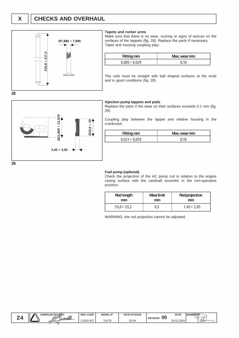
Tapets and rocker armsMake sure that there is no wear, scoring or signs of seizure on thesurfaces of the tappets (fig. 28). Replace the parts if necessary.Tapet and housing coupling play:
The rods must be straight with ball shaped surfaces at the endsand in good conditions (fig. 28).
Injection pump tappets and padsReplace the parts if the wear on their surfaces exceeds 0.1 mm (fig.29).
Coupling play between the tappet and relative housing in thecrankcase:
Fuel pump (optional)Check the projection of the AC pump rod in relation to the enginecasing surface with the canshaft eccentric in the non-operativeposition.
WARNING: the rod projection cannot be adjusted.
Wear limitmm
Rod lengthmm
Rod projectionmm
25COMPILER TECO/ATI ENDORSEDDATE
29.02.2004
REG. CODE
1-5302-637
MODEL N°
51078
DATE OF ISSUE
02-04REVISION 00
XI
30
31
12
34
5
6
7
8
9
10
11
12
13
14
15
6
7
8
1
2
3
4
5
INJECTION EQUIPMENT
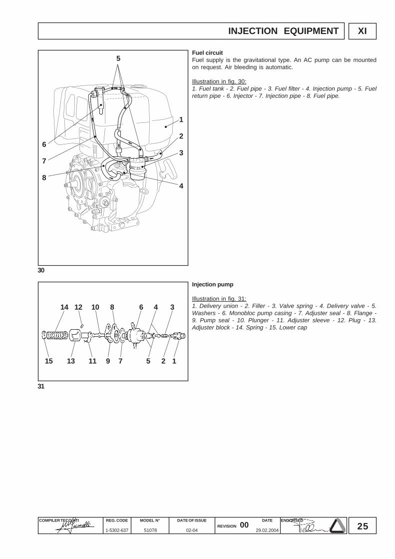
Injection pump
Illustration in fig. 31:1. Delivery union - 2. Filler - 3. Valve spring - 4. Delivery valve - 5.Washers - 6. Monobloc pump casing - 7. Adjuster seal - 8. Flange -9. Pump seal - 10. Plunger - 11. Adjuster sleeve - 12. Plug - 13.Adjuster block - 14. Spring - 15. Lower cap
Fuel circuitFuel supply is the gravitational type. An AC pump can be mountedon request. Air bleeding is automatic.
Illustration in fig. 30:1. Fuel tank - 2. Fuel pipe - 3. Fuel filter - 4. Injection pump - 5. Fuelreturn pipe - 6. Injector - 7. Injection pipe - 8. Fuel pipe.
26COMPILER TECO/ATI ENDORSEDDATE
29.02.2004
REG. CODE
1-5302-637
MODEL N°
51078
DATE OF ISSUE
02-04REVISION 00
XI
33
34
35
32
A
B
25,5 ÷ 29 cc
4,0 ÷ 4,1 mm
4,3 ÷ 5,4 kgm (42,5 ÷ 52,5 Nm)
INJECTION EQUIPMENT
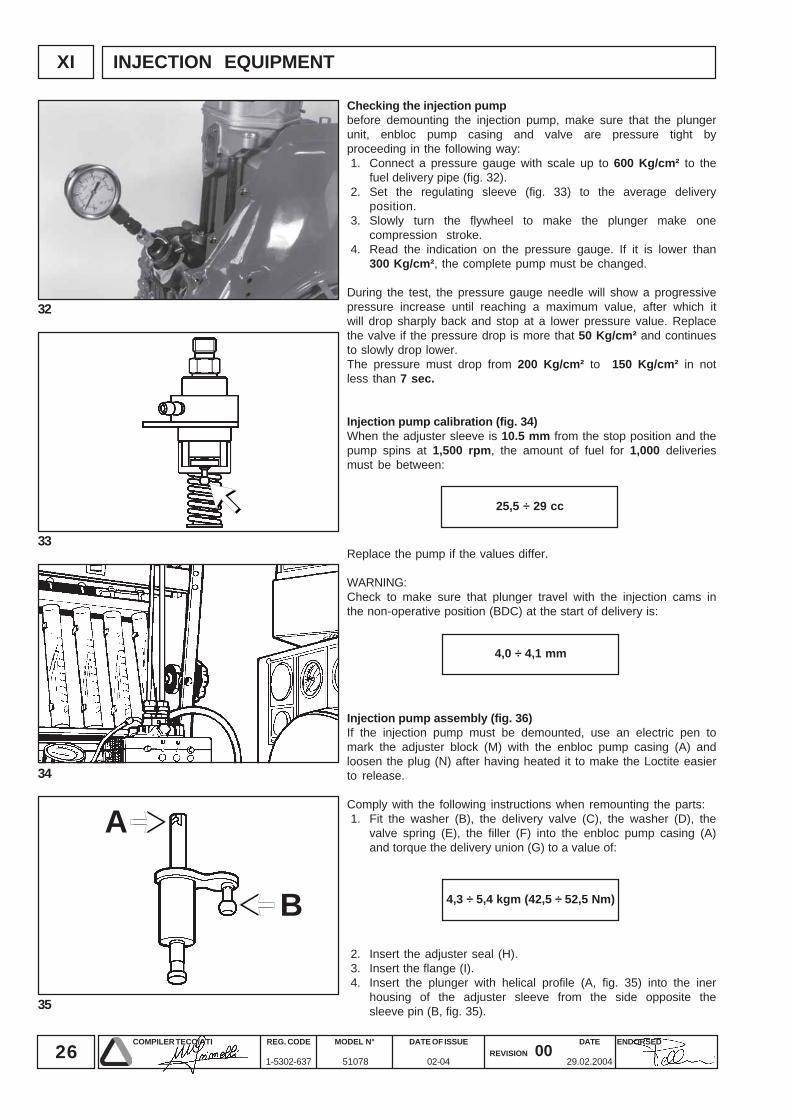
Checking the injection pumpbefore demounting the injection pump, make sure that the plungerunit, enbloc pump casing and valve are pressure tight byproceeding in the following way:1. Connect a pressure gauge with scale up to 600 Kg/cm² to the
fuel delivery pipe (fig. 32).2. Set the regulating sleeve (fig. 33) to the average delivery
position.3. Slowly turn the flywheel to make the plunger make one
compression stroke.4. Read the indication on the pressure gauge. If it is lower than
300 Kg/cm², the complete pump must be changed.
During the test, the pressure gauge needle will show a progressivepressure increase until reaching a maximum value, after which itwill drop sharply back and stop at a lower pressure value. Replacethe valve if the pressure drop is more that 50 Kg/cm² and continuesto slowly drop lower.The pressure must drop from 200 Kg/cm² to 150 Kg/cm² in notless than 7 sec.
Injection pump calibration (fig. 34)When the adjuster sleeve is 10.5 mm from the stop position and thepump spins at 1,500 rpm, the amount of fuel for 1,000 deliveriesmust be between:
2. Insert the adjuster seal (H).3. Insert the flange (I).4. Insert the plunger with helical profile (A, fig. 35) into the iner
housing of the adjuster sleeve from the side opposite thesleeve pin (B, fig. 35).
Replace the pump if the values differ.
WARNING:Check to make sure that plunger travel with the injection cams inthe non-operative position (BDC) at the start of delivery is:
Injection pump assembly (fig. 36)If the injection pump must be demounted, use an electric pen tomark the adjuster block (M) with the enbloc pump casing (A) andloosen the plug (N) after having heated it to make the Loctite easierto release.
Comply with the following instructions when remounting the parts:1. Fit the washer (B), the delivery valve (C), the washer (D), the
valve spring (E), the filler (F) into the enbloc pump casing (A)and torque the delivery union (G) to a value of:
27COMPILER TECO/ATI ENDORSEDDATE
29.02.2004
REG. CODE
1-5302-637
MODEL N°
51078
DATE OF ISSUE
02-04REVISION 00
XI
36
37
38
39
D
1
29 7 5
346810
G F E
B C A
H
L
I
M
O P
N
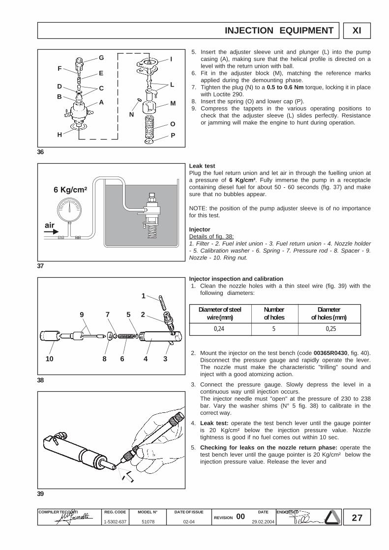
0,24 5 0,25
INJECTION EQUIPMENT
Numberof holes
Diameter of steelwire (mm)
Diameterof holes (mm)
2. Mount the injector on the test bench (code 00365R0430, fig. 40).Disconnect the pressure gauge and rapidly operate the lever.The nozzle must make the characteristic "trilling" sound andinject with a good atomizing action.
3. Connect the pressure gauge. Slowly depress the level in acontinuous way until injection occurs.The injector needle must "open" at the pressure of 230 to 238bar. Vary the washer shims (N° 5 fig. 38) to calibrate in thecorrect way.
4. Leak test: operate the test bench lever until the gauge pointeris 20 Kg/cm² below the injection pressure value. Nozzletightness is good if no fuel comes out within 10 sec.
5. Checking for leaks on the nozzle return phase: operate thetest bench lever until the gauge pointer is 20 Kg/cm² below theinjection pressure value. Release the lever and
Leak testPlug the fuel return union and let air in through the fuelling union ata pressure of 6 Kg/cm². Fully immerse the pump in a receptaclecontaining diesel fuel for about 50 - 60 seconds (fig. 37) and makesure that no bubbles appear.
NOTE: the position of the pump adjuster sleeve is of no importancefor this test.
InjectorDetails of fig. 38:1. Filter - 2. Fuel inlet union - 3. Fuel return union - 4. Nozzle holder- 5. Calibration washer - 6. Spring - 7. Pressure rod - 8. Spacer - 9.Nozzle - 10. Ring nut.
Injector inspection and calibration1. Clean the nozzle holes with a thin steel wire (fig. 39) with the
following diameters:
5. Insert the adjuster sleeve unit and plunger (L) into the pumpcasing (A), making sure that the helical profile is directed on alevel with the return union with ball.
6. Fit in the adjuster block (M), matching the reference marksapplied during the demounting phase.
7. Tighten the plug (N) to a 0.5 to 0.6 Nm torque, locking it in placewith Loctite 290.
8. Insert the spring (O) and lower cap (P).9. Compress the tappets in the various operating positions to
check that the adjuster sleeve (L) slides perfectly. Resistanceor jamming will make the engine to hunt during operation.
28COMPILER TECO/ATI ENDORSEDDATE
29.02.2004
REG. CODE
1-5302-637
MODEL N°
51078
DATE OF ISSUE
02-04REVISION 00
XI
40
41
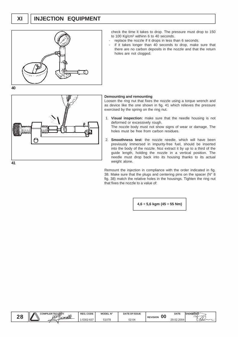
4,6 ÷ 5,6 kgm (45 ÷ 55 Nm)
INJECTION EQUIPMENT
check the time it takes to drop. The pressure must drop to 150to 100 Kg/cm² withinn 6 to 40 seconds.
- replace the nozzle if it drops in less than 6 seconds.- if it takes longer than 40 seconds to drop, make sure that
there are no carbon deposits in the nozzle and that the returnholes are not clogged.
Demounting and remountingLoosen the ring nut that fixes the nozzle using a torque wrench andas device like the one shown in fig. 41 which relieves the pressureexercised by the spring on the ring nut.
1. Visual inspection: make sure that the needle housing is notdeformed or excessively rough.The nozzle body must not show signs of wear or damage. Theholes must be free from carbon residues.
2. Smoothness test: the nozzle needle, which will have beenpreviously immersed in impurity-free fuel, should be insertedinto the body of the nozzle. Noz extract it by up to a third of theguide length, holding the nozzle in a vertical position. Theneedle must drop back into its housing thanks to its actualweight alone.
Remount the injection in compliance with the order indicated in fig.38. Make sure that the plugs and centering pins on the spacer (N° 8fig. 38) match the relative holes in the housings. Tighten the ring nutthat fixes the nozzle to a value of:
29COMPILER TECO/ATI ENDORSEDDATE
29.02.2004
REG. CODE
1-5302-637
MODEL N°
51078
DATE OF ISSUE
02-04REVISION 00
XII
42
43
A V
1
2
3
4
5
6
78
15/5
430
30/1
1550
L.E.
5030
Nx3
3N
x33
Rx2
.5R
x1
Nx2
.5
Gx1
Gx1
Rx2
.5
Mx1
.5
Mx1
Bx1
Vx1.5
Mx1
441000
5
10
15
20
25
A
2000 3000 RPM
ELECTRICAL EQUIPMENT
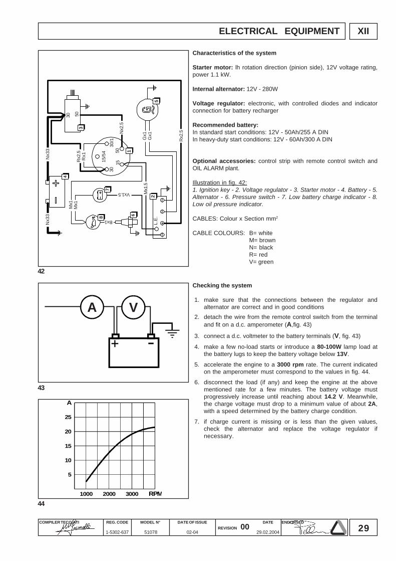
Characteristics of the system
Starter motor: lh rotation direction (pinion side), 12V voltage rating,power 1.1 kW.
Internal alternator: 12V - 280W
Voltage regulator: electronic, with controlled diodes and indicatorconnection for battery recharger
Recommended battery:In standard start conditions: 12V - 50Ah/255 A DINIn heavy-duty start conditions: 12V - 60Ah/300 A DIN
Optional accessories: control strip with remote control switch andOIL ALARM plant.
Illustration in fig. 42:1. Ignition key - 2. Voltage regulator - 3. Starter motor - 4. Battery - 5.Alternator - 6. Pressure switch - 7. Low battery charge indicator - 8.Low oil pressure indicator.
CABLES: Colour x Section mm2
CABLE COLOURS: B= whiteM= brownN= blackR= redV= green
Checking the system
1. make sure that the connections between the regulator andalternator are correct and in good conditions
2. detach the wire from the remote control switch from the terminaland fit on a d.c. amperometer (A,fig. 43)
3. connect a d.c. voltmeter to the battery terminals (V, fig. 43)
4. make a few no-load starts or introduce a 80-100W lamp load atthe battery lugs to keep the battery voltage below 13V.
5. accelerate the engine to a 3000 rpm rate. The current indicatedon the amperometer must correspond to the values in fig. 44.
6. disconnect the load (if any) and keep the engine at the abovementioned rate for a few minutes. The battery voltage mustprogressively increase until reaching about 14.2 V. Meanwhile,the charge voltage must drop to a minimum value of about 2A,with a speed determined by the battery charge condition.
7. if charge current is missing or is less than the given values,check the alternator and replace the voltage regulator ifnecessary.
30COMPILER TECO/ATI ENDORSEDDATE
29.02.2004
REG. CODE
1-5302-637
MODEL N°
51078
DATE OF ISSUE
02-04REVISION 00
XII
46
47
45
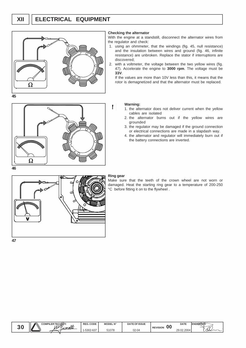
ELECTRICAL EQUIPMENT
Checking the alternatorWith the engine at a standstill, disconnect the alternator wires fromthe regulator and check:1. using an ohmmeter, that the windings (fig. 45, null resistance)
and the insulation between wires and ground (fig. 46, infiniteresistance) are unbroken. Replace the stator if interruptions arediscovered;
2. with a voltmeter, the voltage between the two yellow wires (fig.47). Accelerate the engine to 3000 rpm. The voltage must be33V.If the values are more than 10V less than this, it means that therotor is demagnetized and that the alternator must be replaced.
Warning:1. the alternator does not deliver current when the yellow
cables are isolated2. the alternator burns out if the yellow wires are
grounded3. the regulator may be damaged if the ground connection
or electrical connections are made in a slapdash way.4. the alternator and regulator will immediately burn out if
the battery connections are inverted.
Ring gearMake sure that the teeth of the crown wheel are not worn ordamaged. Heat the starting ring gear to a temperature of 200-250°C before fitting it on to the flywheel .
31COMPILER TECO/ATI ENDORSEDDATE
29.02.2004
REG. CODE
1-5302-637
MODEL N°
51078
DATE OF ISSUE
02-04REVISION 00
XIII
48
49
50
51
A
B
C
ENGINE ASSEMBLY
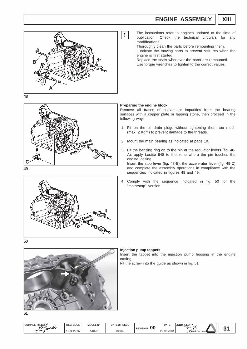
The instructions refer to engines updated at the time ofpublication. Check the technical circulars for anymodifications.Thoroughly clean the parts before remounting them.Lubricate the moving parts to prevent seizures when theengine is first started.Replace the seals whenever the parts are remounted.Use torque wrenches to tighten to the correct values.
Injection pump tappetsInsert the tappet into the injection pump housing in the enginecasing.Fit the screw into the guide as shown in fig. 51
Preparing the engine blockRemove all traces of sealant or impurities from the bearingsurfaces with a copper plate or lapping stone, then proceed in thefollowing way:
1. Fit on the oil drain plugs without tightening them too much(max. 2 Kgm) to prevent damage to the threads.
2. Mount the main bearing as indicated at page 18.
3. Fit the benzing ring on to the pin of the regulator levers (fig. 48-A); apply Loctite 648 to the zone where the pin touches theengine casing.Insert the stop lever (fig. 48-B), the accelerator lever (fig. 49-C)and complete the assembly operations in compliance with thesequencies indicated in figures 48 and 49.
4. Comply with the sequence indicated in fig. 50 for the"motorstop" version.
32COMPILER TECO/ATI ENDORSEDDATE
29.02.2004
REG. CODE
1-5302-637
MODEL N°
51078
DATE OF ISSUE
02-04REVISION 00
52
53
54
55
XII
A
B
E
C D
AABB
CCDD
0,8 ÷ 1,0 kgm (7,8 ÷ 9,8 Nm)
ENGINE ASSEMBLY
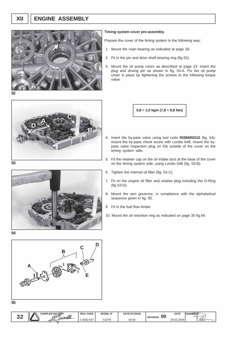
Timing system cover pre-assembly
Prepare the cover of the timing system in the following way:
1. Mount the main bearing as indicated at page 18.
2. Fit in the pin and drive shaft bearing ring (fig 52).
3. Mount the oil pump rotors as described at page 23. Insert theplug and driving pin as shown in fig. 53-A. Fix the oil pumpcover in place by tightening the screws to the following torquevalue:
4. Insert the by-pass valve using tool code 00366R0210 (fig. 54);mount the by-pass check screw with Loctite 648; mount the by-pass valve inspection plug on the outside of the cover on thetiming system side.
5. Fit the retainer cap on the oil intake duct at the base of the coveron the timing system side, using Loctite 648 (fig. 53-B).
6. Tighten the internal oil filter (fig. 53-C).
7. Fit on the engine oil filter and relative plug including the O-Ring(fig 53-D).
8. Mount the rpm governor, in compliance with the alphabeticalsequence given in fig. 55.
9. Fit in the fuel flow limiter
10. Mount the oil retention ring as indicated on page 35 fig.66.
33COMPILER TECO/ATI ENDORSEDDATE
29.02.2004
REG. CODE
1-5302-637
MODEL N°
51078
DATE OF ISSUE
02-04REVISION 00
XIII
56
57
58
59
A
A = 1,7 ÷ 2,0 mm
A
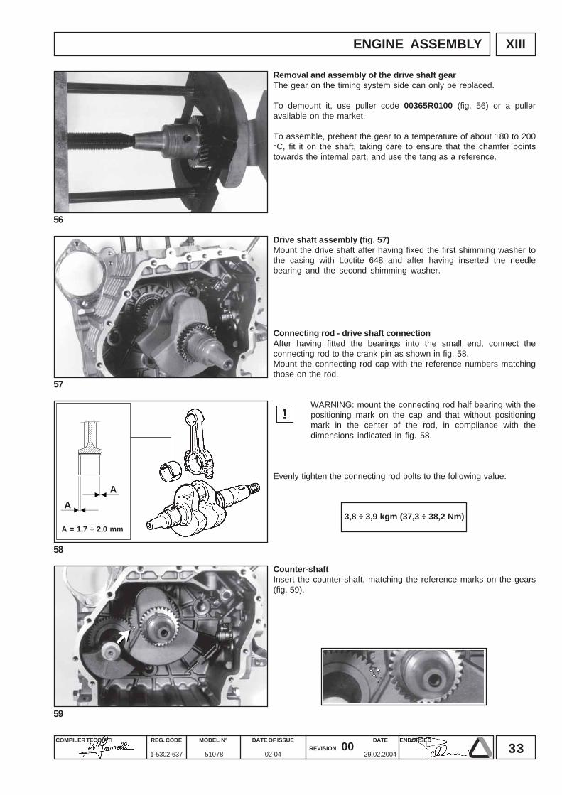
3,8 ÷ 3,9 kgm (37,3 ÷ 38,2 Nm)
ENGINE ASSEMBLY
Removal and assembly of the drive shaft gearThe gear on the timing system side can only be replaced.
To demount it, use puller code 00365R0100 (fig. 56) or a pulleravailable on the market.
To assemble, preheat the gear to a temperature of about 180 to 200°C, fit it on the shaft, taking care to ensure that the chamfer pointstowards the internal part, and use the tang as a reference.
Counter-shaftInsert the counter-shaft, matching the reference marks on the gears(fig. 59).
Connecting rod - drive shaft connectionAfter having fitted the bearings into the small end, connect theconnecting rod to the crank pin as shown in fig. 58.Mount the connecting rod cap with the reference numbers matchingthose on the rod.
WARNING: mount the connecting rod half bearing with thepositioning mark on the cap and that without positioningmark in the center of the rod, in compliance with thedimensions indicated in fig. 58.
Evenly tighten the connecting rod bolts to the following value:
Drive shaft assembly (fig. 57)Mount the drive shaft after having fixed the first shimming washer tothe casing with Loctite 648 and after having inserted the needlebearing and the second shimming washer.
34COMPILER TECO/ATI ENDORSEDDATE
29.02.2004
REG. CODE
1-5302-637
MODEL N°
51078
DATE OF ISSUE
02-04REVISION 00
XIII
60
61
63
62
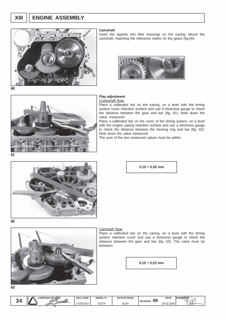
0,10 ÷ 0,30 mm
0,10 ÷ 0,25 mm
ENGINE ASSEMBLY
Play adjustmentCrankshaft float:Place a calibrated bar on the casing, on a level with the timingsystem cover retention surface and use a thickness gauge to checkthe distance between the gear and bar (fig. 61). Note down thevalue measured.Place a calibrated bar on the cover of the timing system, on a levelwith the engine casing retention surface and use a thickness gaugeto check the distance between the bearing ring and bar (fig. 62).Note down the value measured.The sum of the two measured values must be within:
Camshaft float:Place a calibrated bar on the casing, on a level with the timingsystem retention cover and use a thickness gauge to check thedistance between the gear and bar (fig. 63). The value must bebetween:
CamshaftInsert the tappets into their housings on the casing. Mount thecamshaft, matching the reference marks on the gears (fig.60).
35COMPILER TECO/ATI ENDORSEDDATE
29.02.2004
REG. CODE
1-5302-637
MODEL N°
51078
DATE OF ISSUE
02-04REVISION 00
XIII
64
65
66
67
0,10 ÷ 0,25 mm
2,7 ÷ 2,8 kgm (26,5 ÷ 27,5 Nm)
18 ÷ 20 kgm (176,5 ÷ 196,1 Nm)
ENGINE ASSEMBLY
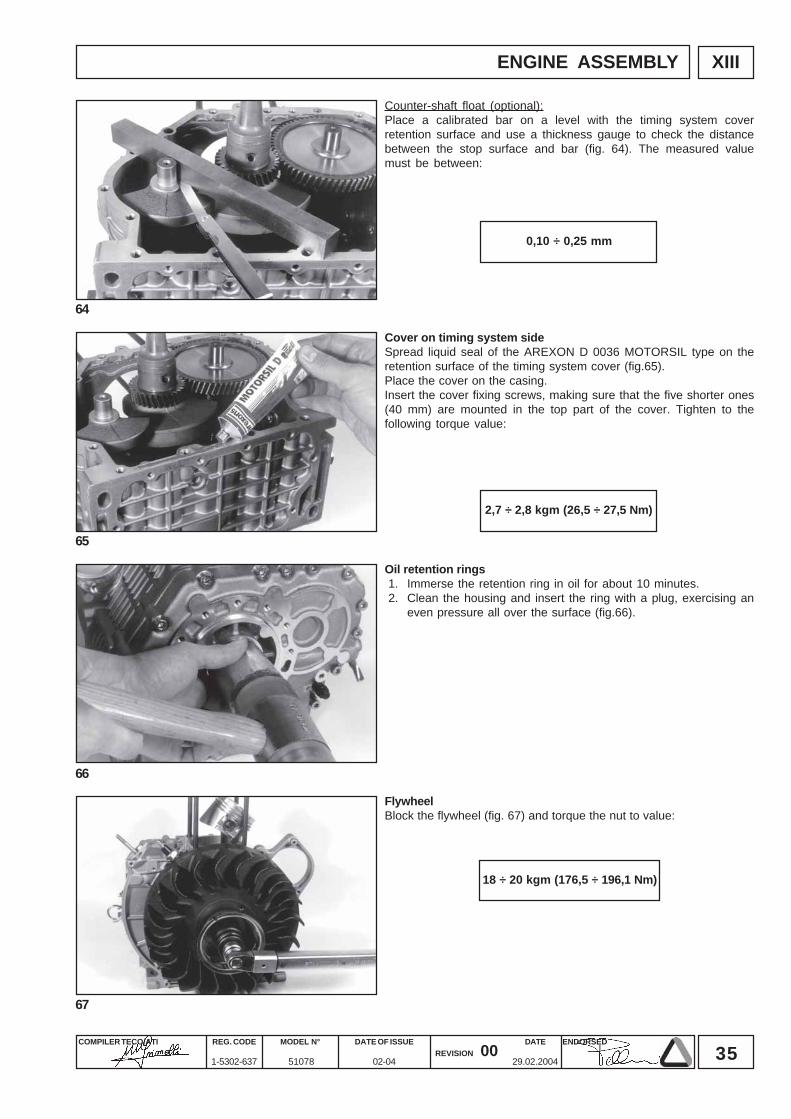
Cover on timing system sideSpread liquid seal of the AREXON D 0036 MOTORSIL type on theretention surface of the timing system cover (fig.65).Place the cover on the casing.Insert the cover fixing screws, making sure that the five shorter ones(40 mm) are mounted in the top part of the cover. Tighten to thefollowing torque value:
Oil retention rings1. Immerse the retention ring in oil for about 10 minutes.2. Clean the housing and insert the ring with a plug, exercising an
even pressure all over the surface (fig.66).
FlywheelBlock the flywheel (fig. 67) and torque the nut to value:
Counter-shaft float (optional):Place a calibrated bar on a level with the timing system coverretention surface and use a thickness gauge to check the distancebetween the stop surface and bar (fig. 64). The measured valuemust be between:
36COMPILER TECO/ATI ENDORSEDDATE
29.02.2004
REG. CODE
1-5302-637
MODEL N°
51078
DATE OF ISSUE
02-04REVISION 00
XIII
TOP
68
69
71
70
0,7 ÷ 0,8 mm
2,2 ÷ 2,7 mm
0,00 ÷ 0,10
0,10 ÷ 0,20
0,20 ÷ 0,30
0,30 ÷ 0,40
0,8
0,9
1,0
1,1
ENGINE ASSEMBLY
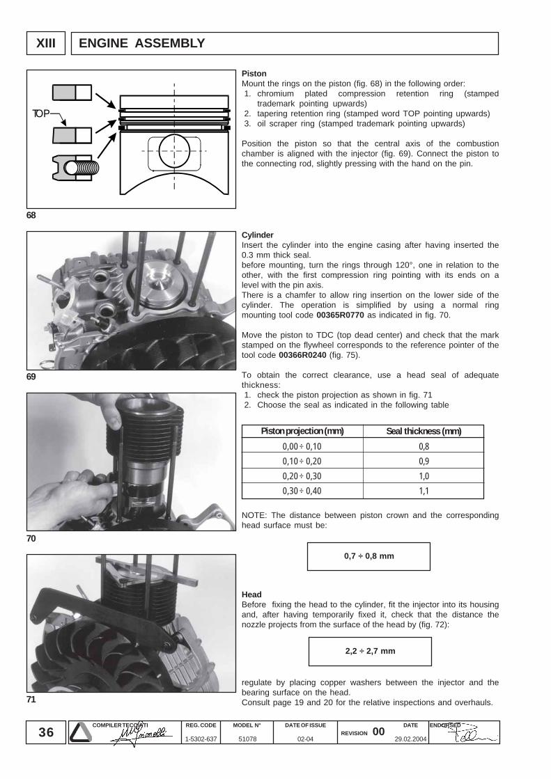
HeadBefore fixing the head to the cylinder, fit the injector into its housingand, after having temporarily fixed it, check that the distance thenozzle projects from the surface of the head by (fig. 72):
CylinderInsert the cylinder into the engine casing after having inserted the0.3 mm thick seal.before mounting, turn the rings through 120°, one in relation to theother, with the first compression ring pointing with its ends on alevel with the pin axis.There is a chamfer to allow ring insertion on the lower side of thecylinder. The operation is simplified by using a normal ringmounting tool code 00365R0770 as indicated in fig. 70.
Move the piston to TDC (top dead center) and check that the markstamped on the flywheel corresponds to the reference pointer of thetool code 00366R0240 (fig. 75).
To obtain the correct clearance, use a head seal of adequatethickness:1. check the piston projection as shown in fig. 712. Choose the seal as indicated in the following table
NOTE: The distance between piston crown and the correspondinghead surface must be:
regulate by placing copper washers between the injector and thebearing surface on the head.Consult page 19 and 20 for the relative inspections and overhauls.
PistonMount the rings on the piston (fig. 68) in the following order:1. chromium plated compression retention ring (stamped
trademark pointing upwards)2. tapering retention ring (stamped word TOP pointing upwards)3. oil scraper ring (stamped trademark pointing upwards)
Position the piston so that the central axis of the combustionchamber is aligned with the injector (fig. 69). Connect the piston tothe connecting rod, slightly pressing with the hand on the pin.
Piston projection (mm) Seal thickness (mm)
37COMPILER TECO/ATI ENDORSEDDATE
29.02.2004
REG. CODE
1-5302-637
MODEL N°
51078
DATE OF ISSUE
02-04REVISION 00
XIII
72
73
74
75
AA
IPIP
4 kgm (39,2 Nm)
3000
3600
18° (42,4 mm)
23° (54,2 mm)
ENGINE ASSEMBLY
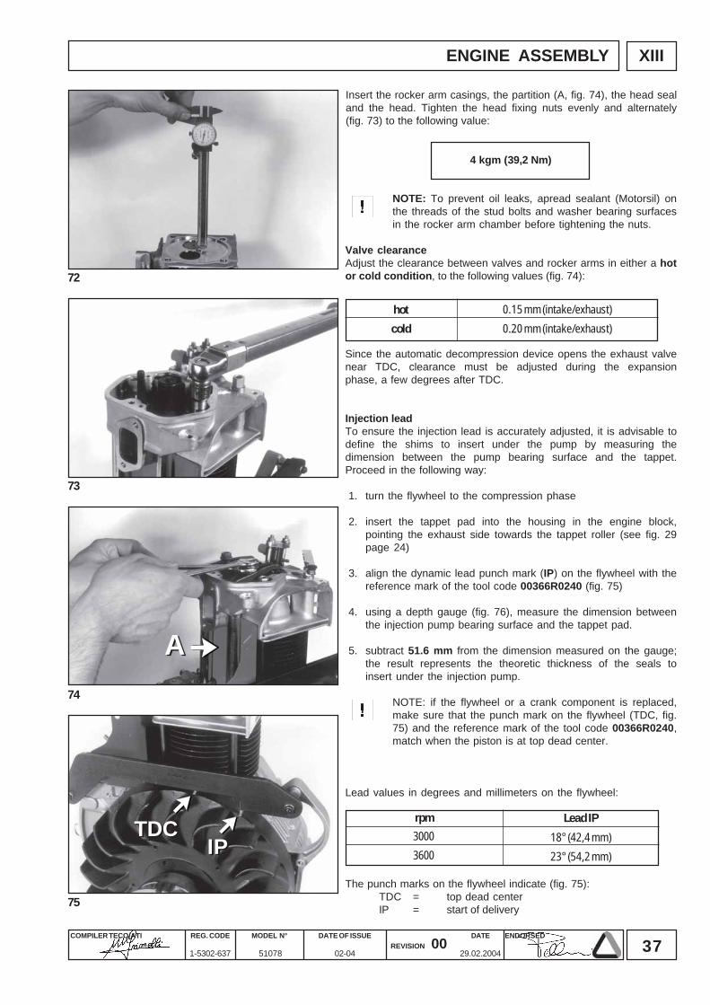
hot
cold
0.15 mm (intake/exhaust)
0.20 mm (intake/exhaust)
NOTE: To prevent oil leaks, apread sealant (Motorsil) onthe threads of the stud bolts and washer bearing surfacesin the rocker arm chamber before tightening the nuts.
Valve clearanceAdjust the clearance between valves and rocker arms in either a hotor cold condition, to the following values (fig. 74):
Insert the rocker arm casings, the partition (A, fig. 74), the head sealand the head. Tighten the head fixing nuts evenly and alternately(fig. 73) to the following value:
Since the automatic decompression device opens the exhaust valvenear TDC, clearance must be adjusted during the expansionphase, a few degrees after TDC.
Injection leadTo ensure the injection lead is accurately adjusted, it is advisable todefine the shims to insert under the pump by measuring thedimension between the pump bearing surface and the tappet.Proceed in the following way:
1. turn the flywheel to the compression phase
2. insert the tappet pad into the housing in the engine block,pointing the exhaust side towards the tappet roller (see fig. 29page 24)
3. align the dynamic lead punch mark (IP) on the flywheel with thereference mark of the tool code 00366R0240 (fig. 75)
4. using a depth gauge (fig. 76), measure the dimension betweenthe injection pump bearing surface and the tappet pad.
5. subtract 51.6 mm from the dimension measured on the gauge;the result represents the theoretic thickness of the seals toinsert under the injection pump.
NOTE: if the flywheel or a crank component is replaced,make sure that the punch mark on the flywheel (TDC, fig.75) and the reference mark of the tool code 00366R0240,match when the piston is at top dead center.
Lead values in degrees and millimeters on the flywheel:
The punch marks on the flywheel indicate (fig. 75):TDC = top dead centerIP = start of delivery
rpm Lead IPTDCTDC
38COMPILER TECO/ATI ENDORSEDDATE
29.02.2004
REG. CODE
1-5302-637
MODEL N°
51078
DATE OF ISSUE
02-04REVISION 00
XIII
78
77
76
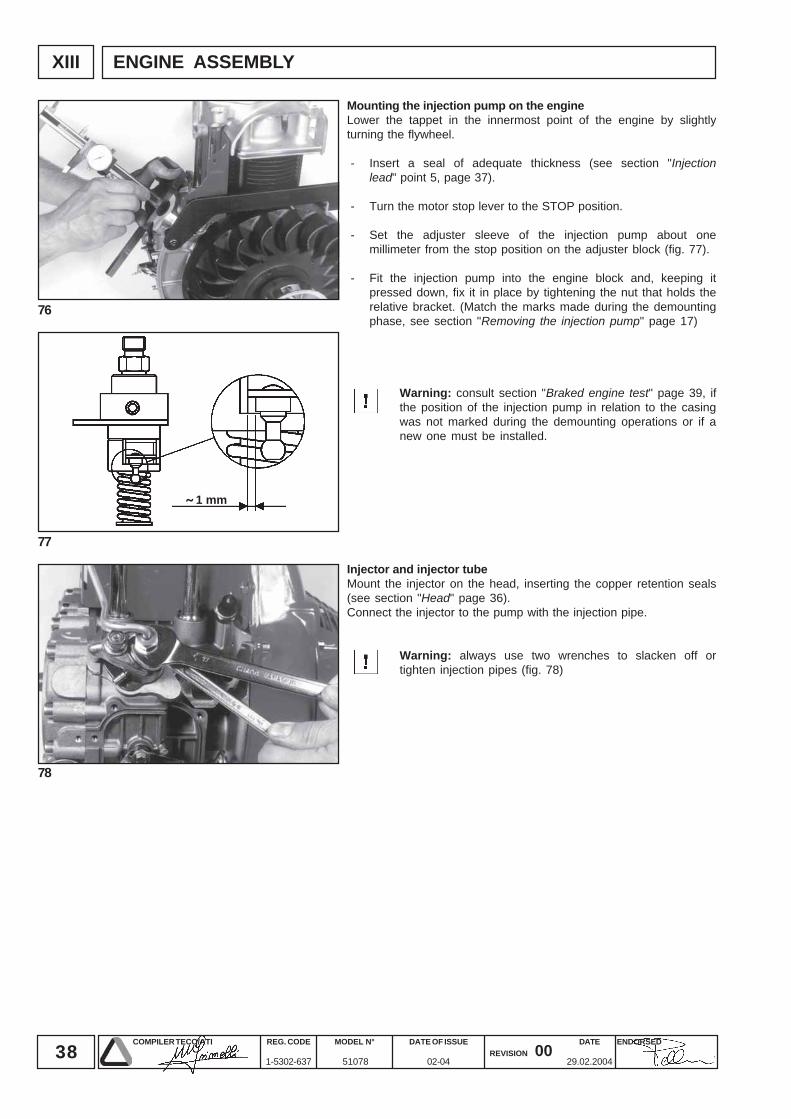
˜ 1 mm
ENGINE ASSEMBLY
Mounting the injection pump on the engineLower the tappet in the innermost point of the engine by slightlyturning the flywheel.
- Insert a seal of adequate thickness (see section "Injectionlead" point 5, page 37).
- Turn the motor stop lever to the STOP position.
- Set the adjuster sleeve of the injection pump about onemillimeter from the stop position on the adjuster block (fig. 77).
- Fit the injection pump into the engine block and, keeping itpressed down, fix it in place by tightening the nut that holds therelative bracket. (Match the marks made during the demountingphase, see section "Removing the injection pump" page 17)
Warning: consult section "Braked engine test" page 39, ifthe position of the injection pump in relation to the casingwas not marked during the demounting operations or if anew one must be installed.
Injector and injector tubeMount the injector on the head, inserting the copper retention seals(see section "Head" page 36).Connect the injector to the pump with the injection pipe.
Warning: always use two wrenches to slacken off ortighten injection pipes (fig. 78)
39COMPILER TECO/ATI ENDORSEDDATE
29.02.2004
REG. CODE
1-5302-637
MODEL N°
51078
DATE OF ISSUE
02-04REVISION 00
XIV
81
80
79
5
15
30
30
30
5
0
0
30%
50%
70%
100%
2000
3000/3600
3000/3600
3000/3600
3000/3600
3000/3600
BBAA
STOP
8° MAX
2,5 mm
A B C
D D
ENGINE TESTING
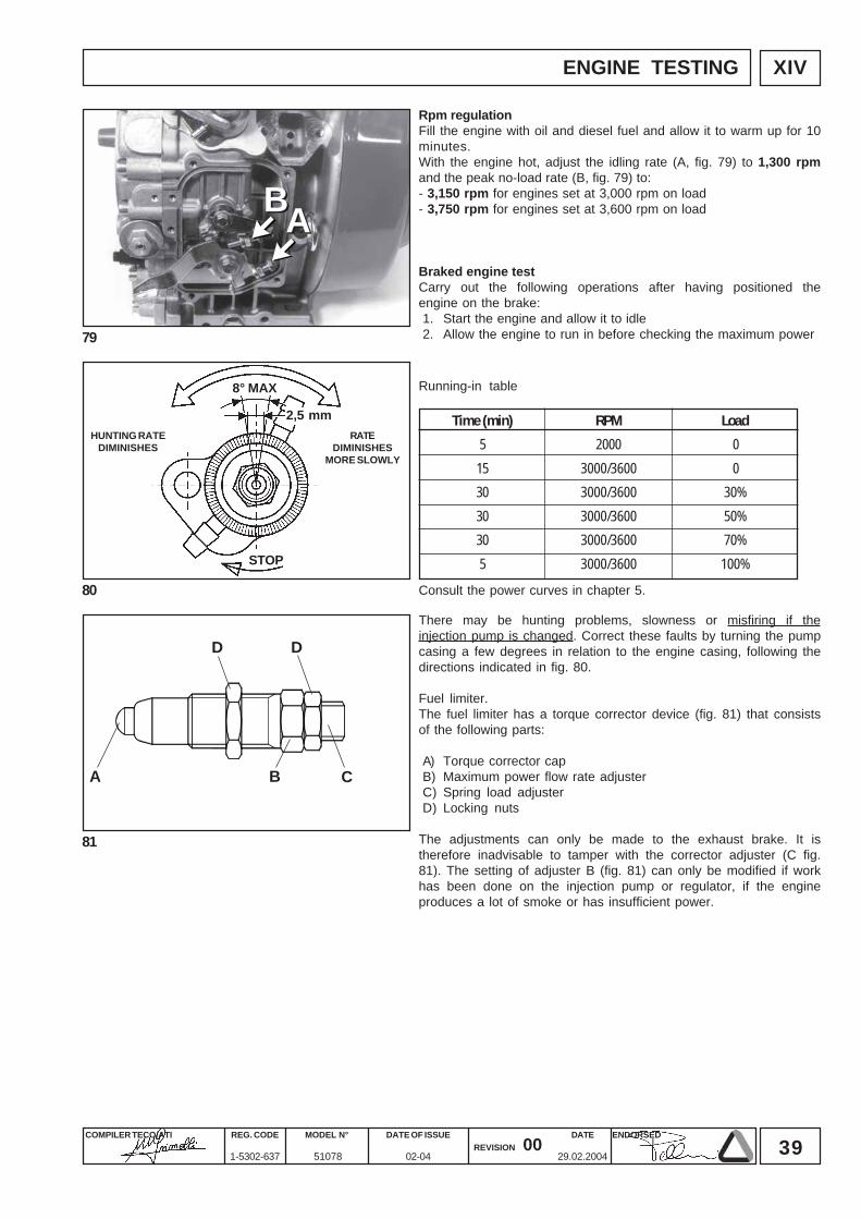
Running-in table
LoadTime (min) RPMHUNTING RATE
DIMINISHESRATE
DIMINISHESMORE SLOWLY
Consult the power curves in chapter 5.
Rpm regulationFill the engine with oil and diesel fuel and allow it to warm up for 10minutes.With the engine hot, adjust the idling rate (A, fig. 79) to 1,300 rpmand the peak no-load rate (B, fig. 79) to:- 3,150 rpm for engines set at 3,000 rpm on load- 3,750 rpm for engines set at 3,600 rpm on load
Braked engine testCarry out the following operations after having positioned theengine on the brake:1. Start the engine and allow it to idle2. Allow the engine to run in before checking the maximum power
There may be hunting problems, slowness or misfiring if theinjection pump is changed. Correct these faults by turning the pumpcasing a few degrees in relation to the engine casing, following thedirections indicated in fig. 80.
Fuel limiter.The fuel limiter has a torque corrector device (fig. 81) that consistsof the following parts:
A) Torque corrector capB) Maximum power flow rate adjusterC) Spring load adjusterD) Locking nuts
The adjustments can only be made to the exhaust brake. It istherefore inadvisable to tamper with the corrector adjuster (C fig.81). The setting of adjuster B (fig. 81) can only be modified if workhas been done on the injection pump or regulator, if the engineproduces a lot of smoke or has insufficient power.
40COMPILER TECO/ATI ENDORSEDDATE
29.02.2004
REG. CODE
1-5302-637
MODEL N°
51078
DATE OF ISSUE
02-04REVISION 00
XV STORAGE
Storage
Prepare engines as follows for storage over 30 days
Temporary protection (1/6 months)
• Let engine run at idling speed in no-load conditions for 15 minutes.• Fill crankcase with protection oil MIL-1-644-P9 and let engine run at 3/4 full speed for 5/10 minutes.• When engine is warm empty oil pan and fill with standard new oil• Remove fuel tube and empty the tank• Remove fuel filter, replace cartridge if dirty and refit• Carefully clean cylinder fins, heads and fan• Seal all openings with tape.• Remove injectors, pour a spoonful of oil type SAE 30 into the cylinders and rotate manualy to distribute the oil. Refit
injectors.• Spray oil type SAE 10W into exhaust and intake manifolds, rocker arms, valves, tappet etc. Grease all unpainted
parts.• Loosen belt• Wrap the engine in a plastic film.• Store in a dry place, if possible not directly on the soil and far from high voltage electric lines.
Permanent protection (over 6 months)
• The following is recommended apart from the above instructions:• For the lubrication and injection system as well as for moving parts use rustproof oil type MIL-L-21260 P10 grade 2, SAE
30 (Ex. ESSO RUST - BAN 623 - AGIP, RUSTIA C. SAE 30) Let the engine run with rustproof oil and drain any excess.• Coat external unpainted surfaces with antirust type MIL-C- 16173D - grade 3 /Ex. ESSO RUST BAN 398 - AGIP, RUSTIA
100/F).
How to prepare the engine for operation
• Clean engine outside• Remove protections and covers• Remove antirust with an appropriate solvent or degreaser.• Remove injector, fill with standard oil, turn crankshaft by a few revolutions, remove oil pan and drain the protective oil.
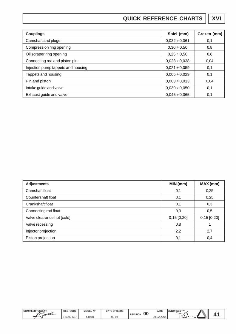
41COMPILER TECO/ATI ENDORSEDDATE
29.02.2004
REG. CODE
1-5302-637
MODEL N°
51078
DATE OF ISSUE
02-04REVISION 00
XVI
0,032 ÷ 0,0610,30 ÷ 0,50
0,25 ÷ 0,50
0,023 ÷ 0,0380,021 ÷ 0,059
0,005 ÷ 0,029
0,003 ÷ 0,0130,030 ÷ 0,050
0,045 ÷ 0,065
0,10,8
0,8
0,040,1
0,1
0,040,1
0,1
MIN (mm)0,10,1
0,1
0,30,15 [0,20]
0,8
2,20,1
MAX (mm)0,250,25
0,3
0,50,15 [0,20]
1
2,70,4
QUICK REFERENCE CHARTS
Spiel (mm) Grezen (mm)CouplingsCamshaft and plugsCompression ring opening
Oil scraper ring opening
Connecting rod and piston pinInjection pump tappets and housing
Tappets and housing
Pin and pistonIntake guide and valve
Exhaust guide and valve
AdjustmentsCamshaft floatCountershaft float
Crankshaft float
Connecting rod floatValve clearance hot [cold]
Valve recessing
Injector projectionPiston projection
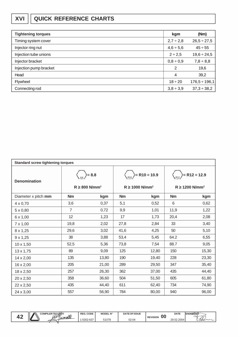
42COMPILER TECO/ATI ENDORSEDDATE
29.02.2004
REG. CODE
1-5302-637
MODEL N°
51078
DATE OF ISSUE
02-04REVISION 00
XVI
= 8.88.8
= R10 = 10.9R10
= R12 = 12.9R12
kgm0,52
1,011,73
2,84
4,255,45
7,54
12,8019,40
29,50
37,0051,50
62,40
80,00
Nm5,1
9,917
27,8
41,653,4
73,8
125190
289
362504
611
784
kgm0,62
1,222,08
3,40
5,106,55
9,05
15,3023,30
35,40
44,4061,80
74,90
96,00
Nm6
11,920,4
33
5064.2
88.7
150228
347
435605
734
940
R ≥≥≥≥≥ 800 N/mm2 R ≥≥≥≥≥ 1000 N/mm2 R ≥≥≥≥≥ 1200 N/mm2
Nm3,6
712
19,8
29,638
52,5
89135
205
257358
435
557
kgm0,37
0,721,23
2,02
3,023,88
5,36
9,0913,80
21,00
26,3036,60
44,40
56,90
4 x 0,705 x 0,80
6 x 1,00
7 x 1,008 x 1,25
9 x 1,25
10 x 1,5013 x 1,75
14 x 2,00
16 x 2,0018 x 2,50
20 x 2,50
22 x 2,5024 x 3,00
kgm2,7 ÷ 2,8
4,6 ÷ 5,6
2 ÷ 2,50,8 ÷ 0,9
2
418 ÷ 20
3,8 ÷ 3,9
(Nm)26,5 ÷ 27,5
45 ÷ 55
19,6 ÷ 24,57,8 ÷ 8,8
19,6
39,2176,5 ÷ 196,1
37,3 ÷ 38,2
QUICK REFERENCE CHARTS
Standard screw tightening torques
Denomination
Diameter x pitch mm
Tightening torquesTiming system cover
Injector ring nut
Injection tube unionsInjector bracket
Injection pump bracket
HeadFlywheel
Connecting rod
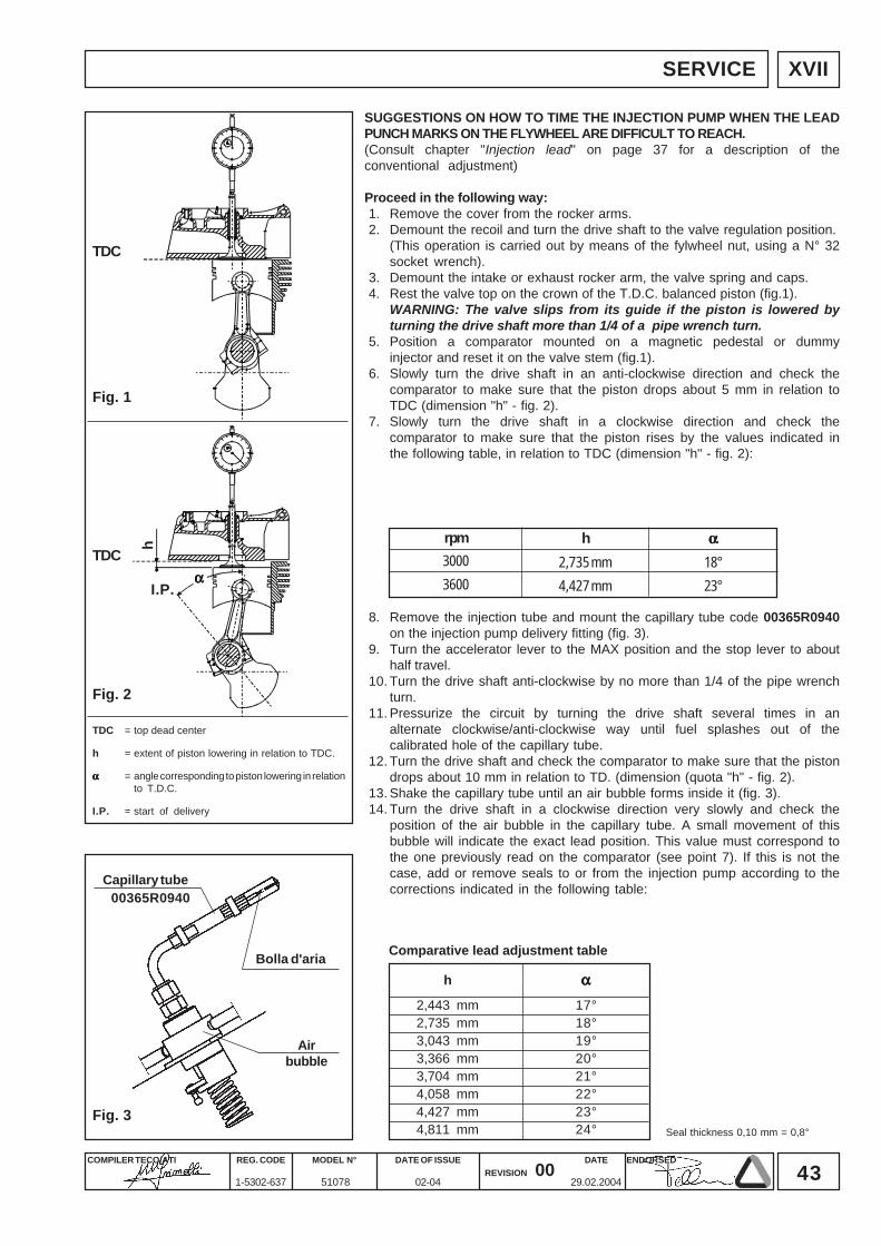
43COMPILER TECO/ATI ENDORSEDDATE
29.02.2004
REG. CODE
1-5302-637
MODEL N°
51078
DATE OF ISSUE
02-04REVISION 00
SERVICE
ααααα
h
I.P.
Fig. 1
Fig. 2
Fig. 3
00365R0940
2,443 mm 17°2,735 mm 18°3,043 mm 19°3,366 mm 20°3,704 mm 21°4,058 mm 22°4,427 mm 23°4,811 mm 24°
h ααααα
3000
3600
2,735 mm
4,427 mm
h
18°
23°
ααααα
XVII
SUGGESTIONS ON HOW TO TIME THE INJECTION PUMP WHEN THE LEADPUNCH MARKS ON THE FLYWHEEL ARE DIFFICULT TO REACH.(Consult chapter "Injection lead" on page 37 for a description of theconventional adjustment)
Proceed in the following way:1. Remove the cover from the rocker arms.2. Demount the recoil and turn the drive shaft to the valve regulation position.
(This operation is carried out by means of the fylwheel nut, using a N° 32socket wrench).
3. Demount the intake or exhaust rocker arm, the valve spring and caps.4. Rest the valve top on the crown of the T.D.C. balanced piston (fig.1).
WARNING: The valve slips from its guide if the piston is lowered byturning the drive shaft more than 1/4 of a pipe wrench turn.
5. Position a comparator mounted on a magnetic pedestal or dummyinjector and reset it on the valve stem (fig.1).
6. Slowly turn the drive shaft in an anti-clockwise direction and check thecomparator to make sure that the piston drops about 5 mm in relation toTDC (dimension "h" - fig. 2).
7. Slowly turn the drive shaft in a clockwise direction and check thecomparator to make sure that the piston rises by the values indicated inthe following table, in relation to TDC (dimension "h" - fig. 2):
8. Remove the injection tube and mount the capillary tube code 00365R0940on the injection pump delivery fitting (fig. 3).
9. Turn the accelerator lever to the MAX position and the stop lever to abouthalf travel.
10. Turn the drive shaft anti-clockwise by no more than 1/4 of the pipe wrenchturn.
11. Pressurize the circuit by turning the drive shaft several times in analternate clockwise/anti-clockwise way until fuel splashes out of thecalibrated hole of the capillary tube.
12. Turn the drive shaft and check the comparator to make sure that the pistondrops about 10 mm in relation to TD. (dimension (quota "h" - fig. 2).
13. Shake the capillary tube until an air bubble forms inside it (fig. 3).14. Turn the drive shaft in a clockwise direction very slowly and check the
position of the air bubble in the capillary tube. A small movement of thisbubble will indicate the exact lead position. This value must correspond tothe one previously read on the comparator (see point 7). If this is not thecase, add or remove seals to or from the injection pump according to thecorrections indicated in the following table:
TDC = top dead center
h = extent of piston lowering in relation to TDC.
ααααα = angle corresponding to piston lowering in relationto T.D.C.
I.P. = start of delivery
rpm
Comparative lead adjustment table
Seal thickness 0,10 mm = 0,8°
Airbubble
Bolla d'aria
Capillary tube
TDC
TDC
44COMPILER TECO/ATI ENDORSEDDATE
29.02.2004
REG. CODE
1-5302-637
MODEL N°
51078
DATE OF ISSUE
02-04REVISION 00
La Lombardini si riserva il diritto di modificare in qualunque momento i dati contenuti in questa pubblicazione.Lombardini se rèserve le droit de modifier, à n'importe quel moment, les données reportées dans cette publication.Data reported in this issue can be modified at any time by Lombardini .Lombardini vorbehält alle Rechte, diese Angabe jederzeit verändern.La Lombardini se reserva el derecho de modificar sin previo aviso los datos de esta publicación.
42100 Reggio Emilia – Italia - ITALYVia Cav. del Lavoro Adelmo Lombardini, 2 - Cas. Post. 1074Tel. (+39) 0522 3891 - Telex 530003 Motlom I – Telegr.: LombarmotorR.E.A. 227083 - Reg. Impr. RE 10875Cod. fiscale e Partita IVA 01829970357 - CEE Code IT 01829970357E-MAIL: [email protected]: http://www.lombardini.it