PDF (4.34 MB) - IOPscience
18
OPEN ACCESS Temperature-dependent Néel wall dynamics in GaMnAs/GaAs To cite this article: J Honolka et al 2010 New J. Phys. 12 093022 View the article online for updates and enhancements. You may also like Determination of interlayer exchange fields acting on individual (Ga,Mn)As layers in (Ga,Mn)As/GaAs multilayers Sunjae Chung, Sangyeop Lee, Taehee Yoo et al. - Switching the uniaxial magnetic anisotropy by ion irradiation induced compensation Ye Yuan, Teyri Amarouche, Chi Xu et al. - Hole spin injection from a GaMnAs layer into GaAs–AlAs–InGaAs resonant tunneling diodes D H Rodrigues, M J S P Brasil, M Orlita et al. - This content was downloaded from IP address 95.65.73.201 on 14/02/2022 at 07:42
Transcript of PDF (4.34 MB) - IOPscience
OPEN ACCESS
Temperature-dependent Néel wall dynamics inGaMnAs/GaAsTo cite this article: J Honolka et al 2010 New J. Phys. 12 093022
View the article online for updates and enhancements.
You may also likeDetermination of interlayer exchange fieldsacting on individual (Ga,Mn)As layers in(Ga,Mn)As/GaAs multilayersSunjae Chung, Sangyeop Lee, TaeheeYoo et al.
-
Switching the uniaxial magnetic anisotropyby ion irradiation induced compensationYe Yuan, Teyri Amarouche, Chi Xu et al.
-
Hole spin injection from a GaMnAs layerinto GaAs–AlAs–InGaAs resonanttunneling diodesD H Rodrigues, M J S P Brasil, M Orlita etal.
-
This content was downloaded from IP address 95.65.73.201 on 14/02/2022 at 07:42
T h e o p e n – a c c e s s j o u r n a l f o r p h y s i c s
New Journal of Physics
Temperature-dependent Néel wall dynamicsin GaMnAs/GaAs
J Honolka1,3, L Herrera Diez1, R K Kremer1, K Kern1, E Placidi2
and F Arciprete2
1 Max-Planck-Institut für Festkörperforschung, Heisenbergstrasse 1,70569 Stuttgart, Germany2 Dipartimento di Fisica, Università di Roma ‘Tor Vergata’ and CNR-INFM,Via della Ricerca Scientifica 1, I-00133 Roma, ItalyE-mail: [email protected]
New Journal of Physics 12 (2010) 093022 (17pp)Received 1 July 2010Published 15 September 2010Online at http://www.njp.org/doi:10.1088/1367-2630/12/9/093022
Abstract. Extensive Kerr microscopy studies reveal strongly temperature-dependent domain wall (DW) dynamics in Hall bars made from compressivelystrained GaMnAs. Depending on the temperature, magnetic charging of the DWsis observed, and the nucleation rates depend on the Hall geometry with respectto the crystal axes. Above a critical temperature where a biaxial-to-uniaxialanisotropy transition occurs, a drastic increase in nucleation events is observed.Below this temperature, the nucleation of domains tends to be rather insensitiveto temperature. This spatially resolved study of the DW dynamics in patternedGaMnAs at variable temperature has important implications for potentialapplications in single DW magneto-logic devices made from ferromagneticsemiconductors.
3 Author to whom any correspondence should be addressed.
New Journal of Physics 12 (2010) 0930221367-2630/10/093022+17$30.00 © IOP Publishing Ltd and Deutsche Physikalische Gesellschaft
2
Contents
1. Magnetic characterization of unpatterned, virgin GaMnAs epilayers 32. Observation of temperature-dependent domain wall (DW) dynamics in patterned
GaMnAs Hall bars 62.1. DW alignment—charging of walls . . . . . . . . . . . . . . . . . . . . . . . . 82.2. Temperature dependence of domain nucleation . . . . . . . . . . . . . . . . . 12
3. Conclusions 15Acknowledgments 16References 16
The ferromagnetic semiconductor GaMnAs [1] has been extensively studied in the past fewyears not only from the viewpoint of basic science but also focusing on the properties thatcan lead to novel applications in spin-based electronics and magneto-logic devices [2, 3]. Forthe latter, a good understanding of domain wall (DW) dynamics is needed in order to controlprocesses such as DW nucleation and propagation. In ferromagnetic GaMnAs with in-planemagnetization, magnetic reversal processes have been studied mostly by means of magneto-transport [4, 5], but with very limited gain of local information about DW nucleation and motion.Magnetic domains in GaMnAs/GaAs were first observed magneto-optically with the aid of agarnet film as an optical magnetic field sensor where large domain structures of a few hundredsof micrometers in size were reported [6]. On the scale of a few micrometers, single DWs havebeen resolved in the static limit by means of electron holography [7] with high spatial resolution.Additionally, we have shown that Kerr microscopy provides full-time and spatially resolvedinformation about the dynamics of in-plane magnetic domains during the magnetization reversalon the scale of a few hundreds of micrometers [8]. Other authors have demonstrated thatscanning Kerr microscopy can provide a spacial resolution down to 500 nm that can be used toimage the magnetization dynamics in smaller structures [9]. Due to the low Curie temperatures(Tc) well below room temperature of most ferromagnetic semiconductors, it is of technicalinterest to study these materials in the highest possible temperature range just below Tc. In thiswork, we present a careful characterization of the temperature-dependent biaxial and uniaxialmagnetic anisotropies in compressively strained GaMnAs and their influence on the evolutionof the magnetic domain structure, thereby identifying limits for DW logic devices in the high-temperature regime. A preferential DW alignment is found to be linked to the change in themagnetic easy axis direction given by the temperature dependence of the uniaxial and biaxialanisotropy contributions. An increase in the number of domain nucleation centers is observedbeyond a critical temperature where a biaxial-to-uniaxial anisotropy transition takes place. Thedependence of this behavior on the geometry of the device is also presented.
The material under study consists of GaMnAs epilayers of 170 nm thickness grown onGaAs(001) substrates by molecular beam epitaxy (MBE). The compressive strain induced by themismatch between the GaMnAs lattice constant and that of the underlying GaAs determines allthe magnetization easy axes to lie within the surface plane [10]. The nominal Mn concentrationis (2.3 ± 0.1)%, and this has been estimated on the basis of flux ratios. A more detaileddescription of the sample growth and material characterization has been given elsewhere [8].The GaMnAs devices used in the Kerr microscopy experiments are Hall bars of 200 µm widthfabricated by standard photolithography and ion milling.
New Journal of Physics 12 (2010) 093022 (http://www.njp.org/)
3
1. Magnetic characterization of unpatterned, virgin GaMnAs epilayers
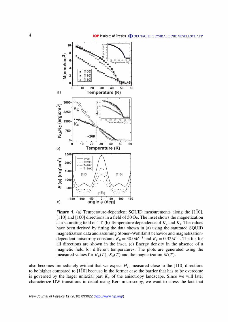
For a full characterization of the magnetic anisotropy within the GaMnAs epilayer, weperformed temperature-dependent superconducting quantum interference device (SQUID) aswell as magneto-optical Kerr effect (MOKE) measurements with magnetic fields applied invarious in-plane directions. SQUID measurements were performed after cooling the sample ina field of 1000 Oe along a chosen direction. Thereafter the field was reduced to 50 Oe and themagnetization was measured in the respective direction with increasing temperature. The resultsare shown in figure 1(a) for fields along three directions [11̄0], [110] and [100]. Also plotted isthe magnetization versus temperature M(T ) (figure 1(a), inset) in a saturating field of H = 1 T.From the temperature-dependent magnetic response at non-saturating fields of H = 50 Oe fordifferent directions, the temperature dependence of the anisotropy constants can be estimatedassuming a Stoner–Wohlfahrt coherent rotation of the magnetization following the total energydensity E(ϕ) =
Kc4 cos2(2ϕ) + Ku cos2 ϕ − M H cos(ϕ − ϕH ), where Kc and Ku are the biaxial
and uniaxial anisotropy constants, M is the magnetization, H is the magnetic field and ϕ and ϕH
are the angles of M and H with the [11̄0] direction. For each temperature the measured SQUIDsignal MSQUID is determined simply by the equation system
∂ E/∂ϕ = 0, (∂2 E/∂2ϕ > 0), (1)
MSQUID= M cos(ϕ − ϕH ). (2)
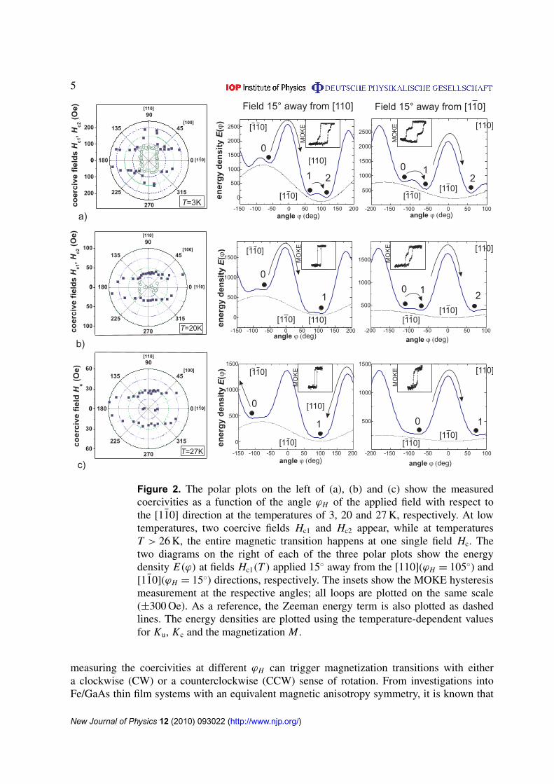
Here, MSQUID is the measured projection of the magnetization M(T ) on the axis of the SQUIDpick-up coils, which are aligned parallel to the magnetic field. While M(T ) is known from theSQUID measurement at saturating fields, Ku and Kc are temperature-dependent parameters tobe derived by fitting. Assuming a magnetization dependence of the anisotropy constants closeto Ku = αM2 and Kc = βM4 [11], we can use equations (1) and (2) to fit the SQUID data,as shown in the inset of figure 1(b). The fits shown for the three directions [11̄0], [110] and[100] are derived using one and the same fit parameters α = 30.0 and β = 0.32 in additionto the magnetization exponents 1.8 and 4.1 for the expressions of Ku and Kc, respectively.In figure 1(b), the temperature dependence of Ku and Kc is plotted as obtained from thefitting procedure. A clear crossover is observed from biaxial to uniaxial magnetic anisotropyat approximately 26 K where Ku = Kc. As a consequence, along the [110] direction the secondderivative of the energy, ∂2 E/∂2ϕ, changes sign at Ku = Kc and the number of local minima inE(ϕ) is reduced from 4 to 2 due to the disappearance of the biaxial-induced energy barrier inthe [110] direction (see figure 1(c)). As extensively shown in magneto-transport measurementsby Pappert et al [5], this crossover becomes directly visible in polar coercivity plots of figure 2,which summarize the coercive fields derived from MOKE hysteresis loops taken in differentdirections with respect to the [11̄0] crystal axis. The shape of the angular dependence of thecoercivities at T = 3 and 27 K clearly confirms the change from a fourfold Kc dominatedsymmetry to a twofold Ku dominated symmetry at low and high temperatures, respectively. Atlow temperatures, in agreement with the literature, the biaxial fourfold symmetry leads to two-step reversals via intermediate local minima in E(ϕ). Specifically for our samples, transitionsat T = 3 K have been shown to be mediated by two individual DWs with DW angles 1ϕ of∼120◦ and ∼60◦, respectively [8], triggered at the coercive fields Hc1 and Hc2. The reversal viaan intermediate state is illustrated in the two right plots of figure 2(a), where E(ϕ) is shownfor fields H = Hc1 applied 15◦ away from the [110] and [11̄0] directions, respectively. For Hc1,the measured values at T = 3 K in the respective direction were taken. From the diagram it
New Journal of Physics 12 (2010) 093022 (http://www.njp.org/)
4
Figure 1. (a) Temperature-dependent SQUID measurements along the [11̄0],[110] and [100] directions in a field of 50 Oe. The inset shows the magnetizationat a saturating field of 1 T. (b) Temperature dependence of Ku and Kc. The valueshave been derived by fitting the data shown in (a) using the saturated SQUIDmagnetization data and assuming Stoner–Wohlfahrt behavior and magnetization-dependent anisotropy constants Ku = 30.0M1.8 and Kc = 0.32M4.1. The fits forall directions are shown in the inset. (c) Energy density in the absence of amagnetic field for different temperatures. The plots are generated using themeasured values for Ku(T ), Kc(T ) and the magnetization M(T ).
also becomes immediately evident that we expect Hc1 measured close to the [110] directionsto be higher compared to [11̄0] because in the former case the barrier that has to be overcomeis governed by the larger uniaxial part Ku of the anisotropy landscape. Since we will latercharacterize DW transitions in detail using Kerr microscopy, we want to stress the fact that
New Journal of Physics 12 (2010) 093022 (http://www.njp.org/)
5
Figure 2. The polar plots on the left of (a), (b) and (c) show the measuredcoercivities as a function of the angle ϕH of the applied field with respect tothe [11̄0] direction at the temperatures of 3, 20 and 27 K, respectively. At lowtemperatures, two coercive fields Hc1 and Hc2 appear, while at temperaturesT > 26 K, the entire magnetic transition happens at one single field Hc. Thetwo diagrams on the right of each of the three polar plots show the energydensity E(ϕ) at fields Hc1(T ) applied 15◦ away from the [110](ϕH = 105◦) and[11̄0](ϕH = 15◦) directions, respectively. The insets show the MOKE hysteresismeasurement at the respective angles; all loops are plotted on the same scale(±300 Oe). As a reference, the Zeeman energy term is also plotted as dashedlines. The energy densities are plotted using the temperature-dependent valuesfor Ku, Kc and the magnetization M .
measuring the coercivities at different ϕH can trigger magnetization transitions with eithera clockwise (CW) or a counterclockwise (CCW) sense of rotation. From investigations intoFe/GaAs thin film systems with an equivalent magnetic anisotropy symmetry, it is known that
New Journal of Physics 12 (2010) 093022 (http://www.njp.org/)
6
0
90
180
270
CCW
CCW
CCW
CCW
CW
CW
CW
CW
0
90
180
270
CCW
CCW CW
CW
K /Ku c < 1 K /Ku c > 1a) b)
2nd globaleasy axis
1st globaleasy axis
= [110] = [110]
one globaleasy axis
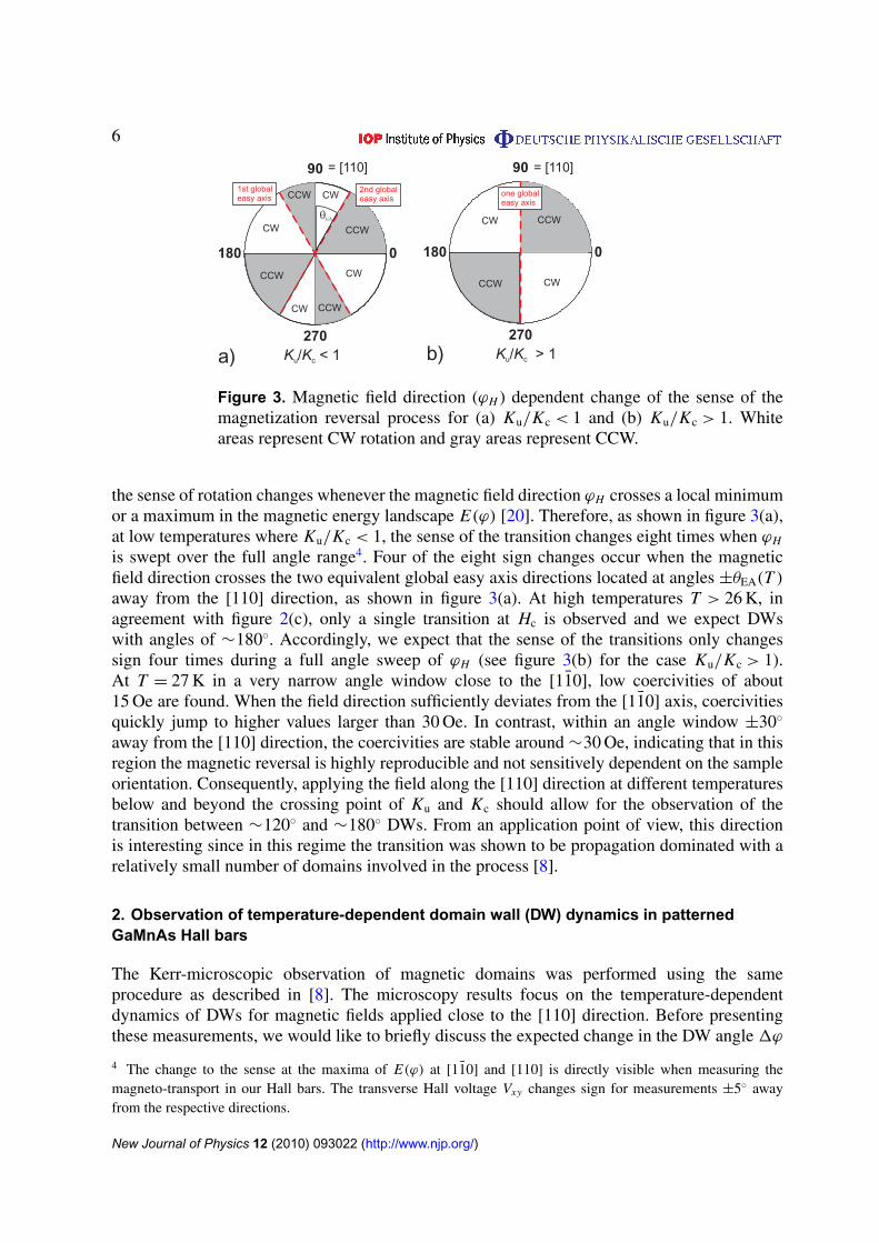
Figure 3. Magnetic field direction (ϕH ) dependent change of the sense of themagnetization reversal process for (a) Ku/Kc < 1 and (b) Ku/Kc > 1. Whiteareas represent CW rotation and gray areas represent CCW.
the sense of rotation changes whenever the magnetic field direction ϕH crosses a local minimumor a maximum in the magnetic energy landscape E(ϕ) [20]. Therefore, as shown in figure 3(a),at low temperatures where Ku/Kc < 1, the sense of the transition changes eight times when ϕH
is swept over the full angle range4. Four of the eight sign changes occur when the magneticfield direction crosses the two equivalent global easy axis directions located at angles ±θEA(T )
away from the [110] direction, as shown in figure 3(a). At high temperatures T > 26 K, inagreement with figure 2(c), only a single transition at Hc is observed and we expect DWswith angles of ∼180◦. Accordingly, we expect that the sense of the transitions only changessign four times during a full angle sweep of ϕH (see figure 3(b) for the case Ku/Kc > 1).At T = 27 K in a very narrow angle window close to the [11̄0], low coercivities of about15 Oe are found. When the field direction sufficiently deviates from the [11̄0] axis, coercivitiesquickly jump to higher values larger than 30 Oe. In contrast, within an angle window ±30◦
away from the [110] direction, the coercivities are stable around ∼30 Oe, indicating that in thisregion the magnetic reversal is highly reproducible and not sensitively dependent on the sampleorientation. Consequently, applying the field along the [110] direction at different temperaturesbelow and beyond the crossing point of Ku and Kc should allow for the observation of thetransition between ∼120◦ and ∼180◦ DWs. From an application point of view, this directionis interesting since in this regime the transition was shown to be propagation dominated with arelatively small number of domains involved in the process [8].
2. Observation of temperature-dependent domain wall (DW) dynamics in patternedGaMnAs Hall bars
The Kerr-microscopic observation of magnetic domains was performed using the sameprocedure as described in [8]. The microscopy results focus on the temperature-dependentdynamics of DWs for magnetic fields applied close to the [110] direction. Before presentingthese measurements, we would like to briefly discuss the expected change in the DW angle 1ϕ
4 The change to the sense at the maxima of E(ϕ) at [11̄0] and [110] is directly visible when measuring themagneto-transport in our Hall bars. The transverse Hall voltage Vxy changes sign for measurements ±5◦ awayfrom the respective directions.
New Journal of Physics 12 (2010) 093022 (http://www.njp.org/)

7
Figure 4. (a) Plot of the angle between the [110] axis and the closest globalminimum direction versus temperature (open squares). The global easy axisreaches the [110] direction at about 26 K where Ku = Kc (compare to figure 1).The corresponding DW angle for a transition via the uniaxial easy axis along[110] with δϕH = 15◦ (b) and δϕH = 0◦ (c) is also plotted (filled squares).
and sense of rotation with temperature as well as with increasing deviations δϕH from the [110]direction.
From simple symmetry arguments reflected in figure 3, it is evident that generally smalldeviations of ±δϕH to both sides of the [110] direction will trigger DW transitions of oppositesense. However, despite the opposite sense in rotation, the absolute DW angles remain exactlythe same. More specifically, at low temperatures T < 26 K and δϕH < θEA, CW (CCW)deviations lead to CW (CCW) transitions at Hc1 and Hc2, whereas for δϕH > θEA, CW (CCW)deviations lead to a CCW (CW) transition. The angle θEA is shown in figure 3(a). For T > 26 K,CW (CCW) deviations always lead to a CCW (CW) transition. For a full understanding of DWdynamics at different temperatures, it is therefore important to trace the temperature-dependentglobal easy axis direction. To give an example of the influence of δϕH on 1ϕ, figure 4 showsthe temperature-dependent angle θEA(T ) of the global easy axis direction with respect to [110]at zero magnetic field together with the expected DW angle of the first transition at Hc1 for
New Journal of Physics 12 (2010) 093022 (http://www.njp.org/)
8
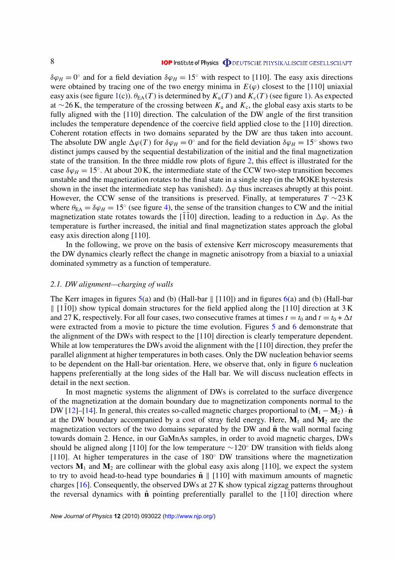
δϕH = 0◦ and for a field deviation δϕH = 15◦ with respect to [110]. The easy axis directionswere obtained by tracing one of the two energy minima in E(ϕ) closest to the [110] uniaxialeasy axis (see figure 1(c)). θEA(T ) is determined by Ku(T ) and Kc(T ) (see figure 1). As expectedat ∼26 K, the temperature of the crossing between Ku and Kc, the global easy axis starts to befully aligned with the [110] direction. The calculation of the DW angle of the first transitionincludes the temperature dependence of the coercive field applied close to the [110] direction.Coherent rotation effects in two domains separated by the DW are thus taken into account.The absolute DW angle 1ϕ(T ) for δϕH = 0◦ and for the field deviation δϕH = 15◦ shows twodistinct jumps caused by the sequential destabilization of the initial and the final magnetizationstate of the transition. In the three middle row plots of figure 2, this effect is illustrated for thecase δϕH = 15◦. At about 20 K, the intermediate state of the CCW two-step transition becomesunstable and the magnetization rotates to the final state in a single step (in the MOKE hysteresisshown in the inset the intermediate step has vanished). 1ϕ thus increases abruptly at this point.However, the CCW sense of the transitions is preserved. Finally, at temperatures T ∼23 Kwhere θEA = δϕH = 15◦ (see figure 4), the sense of the transition changes to CW and the initialmagnetization state rotates towards the [1̄1̄0] direction, leading to a reduction in 1ϕ. As thetemperature is further increased, the initial and final magnetization states approach the globaleasy axis direction along [110].
In the following, we prove on the basis of extensive Kerr microscopy measurements thatthe DW dynamics clearly reflect the change in magnetic anisotropy from a biaxial to a uniaxialdominated symmetry as a function of temperature.
2.1. DW alignment—charging of walls
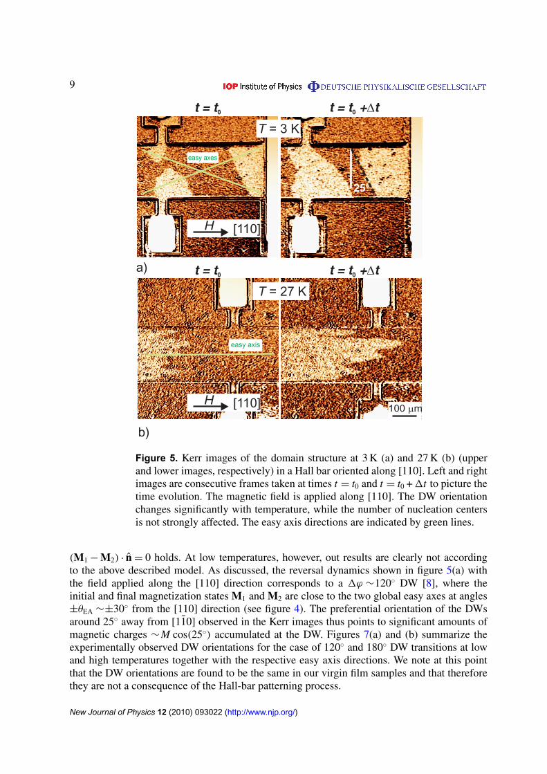
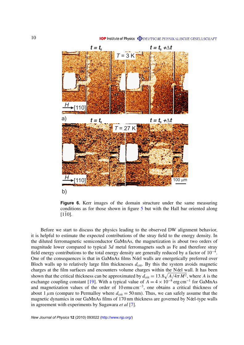
The Kerr images in figures 5(a) and (b) (Hall-bar ‖ [110]) and in figures 6(a) and (b) (Hall-bar‖ [11̄0]) show typical domain structures for the field applied along the [110] direction at 3 Kand 27 K, respectively. For all four cases, two consecutive frames at times t = t0 and t = t0 + 1twere extracted from a movie to picture the time evolution. Figures 5 and 6 demonstrate thatthe alignment of the DWs with respect to the [110] direction is clearly temperature dependent.While at low temperatures the DWs avoid the alignment with the [110] direction, they prefer theparallel alignment at higher temperatures in both cases. Only the DW nucleation behavior seemsto be dependent on the Hall-bar orientation. Here, we observe that, only in figure 6 nucleationhappens preferentially at the long sides of the Hall bar. We will discuss nucleation effects indetail in the next section.
In most magnetic systems the alignment of DWs is correlated to the surface divergenceof the magnetization at the domain boundary due to magnetization components normal to theDW [12]–[14]. In general, this creates so-called magnetic charges proportional to (M1 − M2) · n̂at the DW boundary accompanied by a cost of stray field energy. Here, M1 and M2 are themagnetization vectors of the two domains separated by the DW and n̂ the wall normal facingtowards domain 2. Hence, in our GaMnAs samples, in order to avoid magnetic charges, DWsshould be aligned along [110] for the low temperature ∼120◦ DW transition with fields along[110]. At higher temperatures in the case of 180◦ DW transitions where the magnetizationvectors M1 and M2 are collinear with the global easy axis along [110], we expect the systemto try to avoid head-to-head type boundaries n̂ ‖ [110] with maximum amounts of magneticcharges [16]. Consequently, the observed DWs at 27 K show typical zigzag patterns throughoutthe reversal dynamics with n̂ pointing preferentially parallel to the [11̄0] direction where
New Journal of Physics 12 (2010) 093022 (http://www.njp.org/)
9
100 m
H [110]
H [110]
T = 3 K
T = 27 K
a)
b)
25°
easy axes
easy axis
t = t0 t = t + t0
t = t0 t = t + t0
Figure 5. Kerr images of the domain structure at 3 K (a) and 27 K (b) (upperand lower images, respectively) in a Hall bar oriented along [110]. Left and rightimages are consecutive frames taken at times t = t0 and t = t0 + 1t to picture thetime evolution. The magnetic field is applied along [110]. The DW orientationchanges significantly with temperature, while the number of nucleation centersis not strongly affected. The easy axis directions are indicated by green lines.
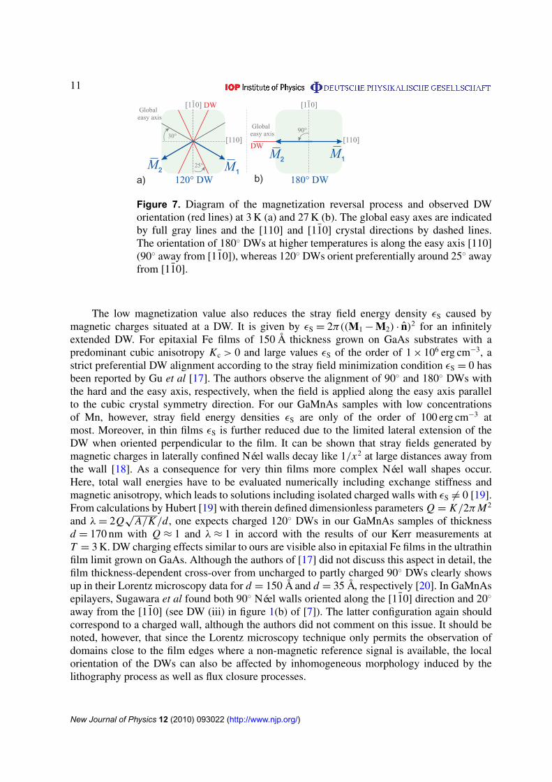
(M1 − M2) · n̂ = 0 holds. At low temperatures, however, out results are clearly not accordingto the above described model. As discussed, the reversal dynamics shown in figure 5(a) withthe field applied along the [110] direction corresponds to a 1ϕ ∼120◦ DW [8], where theinitial and final magnetization states M1 and M2 are close to the two global easy axes at angles±θEA ∼±30◦ from the [110] direction (see figure 4). The preferential orientation of the DWsaround 25◦ away from [11̄0] observed in the Kerr images thus points to significant amounts ofmagnetic charges ∼M cos(25◦) accumulated at the DW. Figures 7(a) and (b) summarize theexperimentally observed DW orientations for the case of 120◦ and 180◦ DW transitions at lowand high temperatures together with the respective easy axis directions. We note at this pointthat the DW orientations are found to be the same in our virgin film samples and that thereforethey are not a consequence of the Hall-bar patterning process.
New Journal of Physics 12 (2010) 093022 (http://www.njp.org/)
10
3 K
T = 27 K
[110]
100 m
b)
a)
a)
[110]
T = 3 K
b)
T = 27 K
[110] 100 m
TT = 7722 2T = 27 K
H
H
t = t0 t = t + t0
t = t0 t = t + t0
Figure 6. Kerr images of the domain structure under the same measuringconditions as for those shown in figure 5 but with the Hall bar oriented along[11̄0].
Before we start to discuss the physics leading to the observed DW alignment behavior,it is helpful to estimate the expected contributions of the stray field to the energy density. Inthe diluted ferromagnetic semiconductor GaMnAs, the magnetization is about two orders ofmagnitude lower compared to typical 3d metal ferromagnets such as Fe and therefore strayfield energy contributions to the total energy density are generally reduced by a factor of 10−4.One of the consequences is that in GaMnAs films Néel walls are energetically preferred overBloch walls up to relatively large film thicknesses dcrit. By this the system avoids magneticcharges at the film surfaces and encounters volume charges within the Néel wall. It has beenshown that the critical thickness can be approximated by dcrit = 13.8
√A/4π M2, where A is the
exchange coupling constant [19]. With a typical value of A = 4 × 10⁻⁸ erg cm−1 for GaMnAsand magnetization values of the order of 10 emu cm−3, one obtains a critical thickness ofabout 1 µm (compare to Permalloy where dcrit = 50 nm). Thus, we can safely assume that themagnetic dynamics in our GaMnAs films of 170 nm thickness are governed by Néel-type wallsin agreement with experiments by Sugawara et al [7].
New Journal of Physics 12 (2010) 093022 (http://www.njp.org/)
11
[110]
[110] DWGlobal
easy axis
120° DW
25°
Globaleasy axis
DWM2 M1
[110]
180° DW
[110]90°
M2 M1
30°
a) b)
Figure 7. Diagram of the magnetization reversal process and observed DWorientation (red lines) at 3 K (a) and 27 K (b). The global easy axes are indicatedby full gray lines and the [110] and [11̄0] crystal directions by dashed lines.The orientation of 180◦ DWs at higher temperatures is along the easy axis [110](90◦ away from [11̄0]), whereas 120◦ DWs orient preferentially around 25◦ awayfrom [11̄0].
The low magnetization value also reduces the stray field energy density εS caused bymagnetic charges situated at a DW. It is given by εS = 2π((M1 − M2) · n̂)2 for an infinitelyextended DW. For epitaxial Fe films of 150 Å thickness grown on GaAs substrates with apredominant cubic anisotropy Kc > 0 and large values εS of the order of 1 × 10⁶ erg cm−3, astrict preferential DW alignment according to the stray field minimization condition εS = 0 hasbeen reported by Gu et al [17]. The authors observe the alignment of 90◦ and 180◦ DWs withthe hard and the easy axis, respectively, when the field is applied along the easy axis parallelto the cubic crystal symmetry direction. For our GaMnAs samples with low concentrationsof Mn, however, stray field energy densities εS are only of the order of 100 erg cm−3 atmost. Moreover, in thin films εS is further reduced due to the limited lateral extension of theDW when oriented perpendicular to the film. It can be shown that stray fields generated bymagnetic charges in laterally confined Néel walls decay like 1/x2 at large distances away fromthe wall [18]. As a consequence for very thin films more complex Néel wall shapes occur.Here, total wall energies have to be evaluated numerically including exchange stiffness andmagnetic anisotropy, which leads to solutions including isolated charged walls with εS 6= 0 [19].From calculations by Hubert [19] with therein defined dimensionless parameters Q = K/2π M2
and λ = 2Q√
A/K/d, one expects charged 120◦ DWs in our GaMnAs samples of thicknessd = 170 nm with Q ≈ 1 and λ ≈ 1 in accord with the results of our Kerr measurements atT = 3 K. DW charging effects similar to ours are visible also in epitaxial Fe films in the ultrathinfilm limit grown on GaAs. Although the authors of [17] did not discuss this aspect in detail, thefilm thickness-dependent cross-over from uncharged to partly charged 90◦ DWs clearly showsup in their Lorentz microscopy data for d = 150 Å and d = 35 Å, respectively [20]. In GaMnAsepilayers, Sugawara et al found both 90◦ Néel walls oriented along the [11̄0] direction and 20◦
away from the [11̄0] (see DW (iii) in figure 1(b) of [7]). The latter configuration again shouldcorrespond to a charged wall, although the authors did not comment on this issue. It should benoted, however, that since the Lorentz microscopy technique only permits the observation ofdomains close to the film edges where a non-magnetic reference signal is available, the localorientation of the DWs can also be affected by inhomogeneous morphology induced by thelithography process as well as flux closure processes.
New Journal of Physics 12 (2010) 093022 (http://www.njp.org/)
12
24 K 33 K
H[110]
100 mµ
3 K 9 Kb)
c) d)
a)
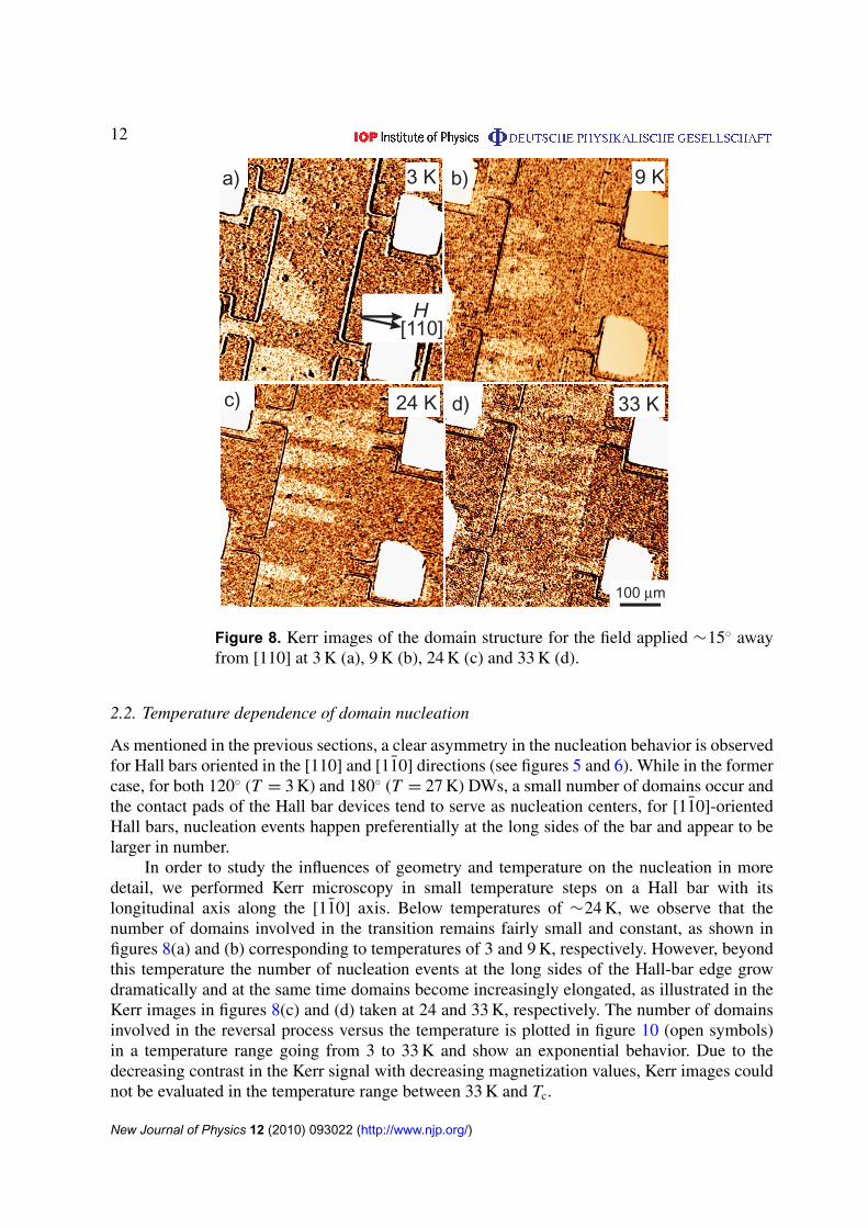
Figure 8. Kerr images of the domain structure for the field applied ∼15◦ awayfrom [110] at 3 K (a), 9 K (b), 24 K (c) and 33 K (d).
2.2. Temperature dependence of domain nucleation
As mentioned in the previous sections, a clear asymmetry in the nucleation behavior is observedfor Hall bars oriented in the [110] and [11̄0] directions (see figures 5 and 6). While in the formercase, for both 120◦ (T = 3 K) and 180◦ (T = 27 K) DWs, a small number of domains occur andthe contact pads of the Hall bar devices tend to serve as nucleation centers, for [11̄0]-orientedHall bars, nucleation events happen preferentially at the long sides of the bar and appear to belarger in number.
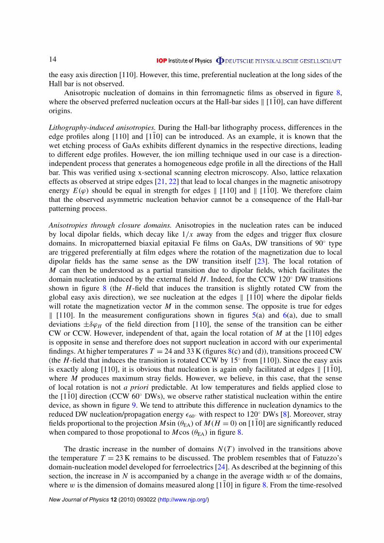
In order to study the influences of geometry and temperature on the nucleation in moredetail, we performed Kerr microscopy in small temperature steps on a Hall bar with itslongitudinal axis along the [11̄0] axis. Below temperatures of ∼24 K, we observe that thenumber of domains involved in the transition remains fairly small and constant, as shown infigures 8(a) and (b) corresponding to temperatures of 3 and 9 K, respectively. However, beyondthis temperature the number of nucleation events at the long sides of the Hall-bar edge growdramatically and at the same time domains become increasingly elongated, as illustrated in theKerr images in figures 8(c) and (d) taken at 24 and 33 K, respectively. The number of domainsinvolved in the reversal process versus the temperature is plotted in figure 10 (open symbols)in a temperature range going from 3 to 33 K and show an exponential behavior. Due to thedecreasing contrast in the Kerr signal with decreasing magnetization values, Kerr images couldnot be evaluated in the temperature range between 33 K and Tc.
New Journal of Physics 12 (2010) 093022 (http://www.njp.org/)
13
a) T = 3 K
[110]H
b)
100 mµ
T = 27 K
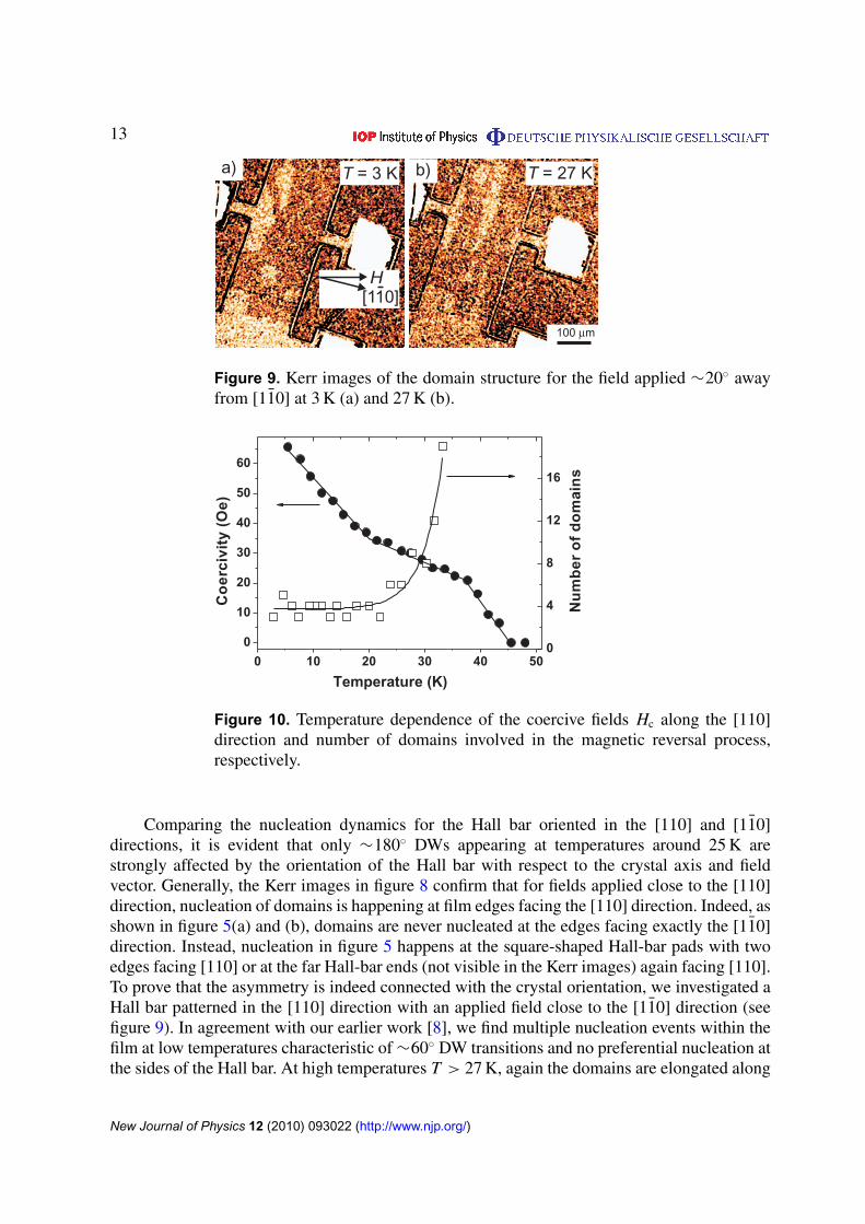
Figure 9. Kerr images of the domain structure for the field applied ∼20◦ awayfrom [11̄0] at 3 K (a) and 27 K (b).
0 10 20 30 40 50
0
10
20
30
40
50
60
0
4
8
12
16
Co
erci
vity
(Oe)
Temperature (K)
Nu
mb
ero
fd
om
ain
s
Figure 10. Temperature dependence of the coercive fields Hc along the [110]direction and number of domains involved in the magnetic reversal process,respectively.
Comparing the nucleation dynamics for the Hall bar oriented in the [110] and [11̄0]directions, it is evident that only ∼180◦ DWs appearing at temperatures around 25 K arestrongly affected by the orientation of the Hall bar with respect to the crystal axis and fieldvector. Generally, the Kerr images in figure 8 confirm that for fields applied close to the [110]direction, nucleation of domains is happening at film edges facing the [110] direction. Indeed, asshown in figure 5(a) and (b), domains are never nucleated at the edges facing exactly the [11̄0]direction. Instead, nucleation in figure 5 happens at the square-shaped Hall-bar pads with twoedges facing [110] or at the far Hall-bar ends (not visible in the Kerr images) again facing [110].To prove that the asymmetry is indeed connected with the crystal orientation, we investigated aHall bar patterned in the [110] direction with an applied field close to the [11̄0] direction (seefigure 9). In agreement with our earlier work [8], we find multiple nucleation events within thefilm at low temperatures characteristic of ∼60◦ DW transitions and no preferential nucleation atthe sides of the Hall bar. At high temperatures T > 27 K, again the domains are elongated along
New Journal of Physics 12 (2010) 093022 (http://www.njp.org/)
14
the easy axis direction [110]. However, this time, preferential nucleation at the long sides of theHall bar is not observed.
Anisotropic nucleation of domains in thin ferromagnetic films as observed in figure 8,where the observed preferred nucleation occurs at the Hall-bar sides ‖ [11̄0], can have differentorigins.
Lithography-induced anisotropies. During the Hall-bar lithography process, differences in theedge profiles along [110] and [11̄0] can be introduced. As an example, it is known that thewet etching process of GaAs exhibits different dynamics in the respective directions, leadingto different edge profiles. However, the ion milling technique used in our case is a direction-independent process that generates a homogeneous edge profile in all the directions of the Hallbar. This was verified using x-sectional scanning electron microscopy. Also, lattice relaxationeffects as observed at stripe edges [21, 22] that lead to local changes in the magnetic anisotropyenergy E(ϕ) should be equal in strength for edges ‖ [110] and ‖ [11̄0]. We therefore claimthat the observed asymmetric nucleation behavior cannot be a consequence of the Hall-barpatterning process.
Anisotropies through closure domains. Anisotropies in the nucleation rates can be inducedby local dipolar fields, which decay like 1/x away from the edges and trigger flux closuredomains. In micropatterned biaxial epitaxial Fe films on GaAs, DW transitions of 90◦ typeare triggered preferentially at film edges where the rotation of the magnetization due to localdipolar fields has the same sense as the DW transition itself [23]. The local rotation ofM can then be understood as a partial transition due to dipolar fields, which facilitates thedomain nucleation induced by the external field H . Indeed, for the CCW 120◦ DW transitionsshown in figure 8 (the H -field that induces the transition is slightly rotated CW from theglobal easy axis direction), we see nucleation at the edges ‖ [11̄0] where the dipolar fieldswill rotate the magnetization vector M in the common sense. The opposite is true for edges‖ [110]. In the measurement configurations shown in figures 5(a) and 6(a), due to smalldeviations ±δϕH of the field direction from [110], the sense of the transition can be eitherCW or CCW. However, independent of that, again the local rotation of M at the [110] edgesis opposite in sense and therefore does not support nucleation in accord with our experimentalfindings. At higher temperatures T = 24 and 33 K (figures 8(c) and (d)), transitions proceed CW(the H -field that induces the transition is rotated CCW by 15◦ from [110]). Since the easy axisis exactly along [110], it is obvious that nucleation is again only facilitated at edges ‖ [11̄0],where M produces maximum stray fields. However, we believe, in this case, that the senseof local rotation is not a priori predictable. At low temperatures and fields applied close tothe [11̄0] direction (CCW 60◦ DWs), we observe rather statistical nucleation within the entiredevice, as shown in figure 9. We tend to attribute this difference in nucleation dynamics to thereduced DW nucleation/propagation energy ε60◦ with respect to 120◦ DWs [8]. Moreover, strayfields proportional to the projection Msin (θEA) of M(H = 0) on [11̄0] are significantly reducedwhen compared to those propotional to Mcos (θEA) in figure 8.
The drastic increase in the number of domains N (T ) involved in the transitions abovethe temperature T = 23 K remains to be discussed. The problem resembles that of Fatuzzo’sdomain-nucleation model developed for ferroelectrics [24]. As described at the beginning of thissection, the increase in N is accompanied by a change in the average width w of the domains,where w is the dimension of domains measured along [11̄0] in figure 8. From the time-resolved
New Journal of Physics 12 (2010) 093022 (http://www.njp.org/)
15
dynamics visible in our Kerr movies above T = 24 K, it is evident that after nucleation of adomain at the Hall-bar edges, DW propagation is mainly taking place in the [110] direction withlittle change in w of the respective domain. Following Fatuzzo, we therefore attribute the drasticincrease in N to a complex interplay of temperature-dependent nucleation rates 0(T ) at the filmedges, a reduced DW mobility µ[11̄0] along [11̄0] and effects of coalescence of domains. If wc isthe average domain width at the coercive field Hc where 50% of the area of the film has switched,then the respective number of domains in a given section of the Hall bar with a length l ‖ [11̄0] isapproximately Nc = l/2wc. Here, wc will be a function of the mobilities along µ[110] and µ[11̄0]
and the nucleation rates 0. With this we can qualitatively understand the temperature-dependentnucleation dynamics. The Kerr data prove that with increasing temperature and especially forT > 20 K, the ratio between µ[110] and µ[11̄0] is significantly shifted toward propagation along[110], which assuming a constant 0 would reduce wc and increase Nc. On the other hand,we expect 0 to increase with temperature according to a thermally activated process, whichsupports coalescence of domains at an early stage after nucleation. Generally, both a decreasein the mobilities and 0 leads to an increase in the coercive field Hc at constant sweep rates ofthe magnetic field. Indeed, the temperature dependence of Hc shown in figure 10 (full symbols)indicates a distinct decrease in slope at T ≈ 20 K, which points toward a change in the mobilitiesand/or 0 (M decreases rather monotonously in this temperature range as shown in the inset offigure 1(a)). Sudden changes in µ[11̄0] or 0 would not be unexpected since they occur in closeproximity to the crossing point between Ku and Kc (∼26 K ), where the magnetic transitionschange their character. Above the crossing temperature, we interpret the drastic increase inN (T ) to be mainly due to a monotonous reduction in µ[11̄0]. As previously mentioned, thedramatic change in the nucleation behavior roughly coincides with the onset of the uniaxialanisotropy dominated temperature regime and therefore may be linked to the structural seed ofthe uniaxial contribution to the magneto-crystalline anisotropy energy. The origin of the uniaxialanisotropy is still under debate. However, some authors tend to attribute it to an anisotropicdynamics during sample growth. This approach proposes that the Mn atoms are preferentiallyincorporated due to the layer-by-layer reconstruction of the surface during growth making the[110] and [11̄0] directions inequivalent [6, 25]. It is well known that DW dynamics are highlysensitive to the presence of defects in the structure of the magnetic material where these defectscan act both as domain nucleation centers and as DW pinning centers. Therefore, a preferentialarrangement of the Mn atoms inside the structure potentially contributing to the appearanceof the magnetic uniaxial anisotropy can also play an important role in the DW dynamics. Thispreferential incorporation of Mn could create an anisotropic arrangement of DW pinning centersfor the [110] direction, with respect to the [11̄0] direction, giving rise to the different DWvelocities we observe along these two crystalline axes.
3. Conclusions
This work presents an extensive characterization of the temperature-dependent magnetic domainwall (DW) dynamics in Hall bars made from compressively strained GaMnAs and identifieslimits for single DW logic devices in the high-temperature regime. The Kerr microscopy allowsus to locally observe nucleation events of domains as well as the alignment and propagationbehavior of DWs. A clear correlation of the preferential DW alignment with the temperature-dependent magnetic easy axis direction is found. The latter is determined by the temperature-dependent in-plane uniaxial and biaxial anisotropy energy contributions. At low temperatures,
New Journal of Physics 12 (2010) 093022 (http://www.njp.org/)
16
magnetically charged DWs with DW angles considerably smaller than 180◦ are observed. Abovethe biaxial-to-uniaxial transition temperature, this charging effect is lost and DWs are orientedalong the easy axis. Domain nucleation happens almost exclusively at Hall-bar edges alignedalong the [11̄0] uniaxial hard axis direction. This behavior is attributed to small demagnetizingfield contributions at the edges of the device, which locally facilitate the magnetic transitionand therefore nucleation of domains: the mechanism is asymmetric and favors nucleation atedges ‖ [11̄0]. Our extensive study of domain nucleation and propagation dynamics at variabletemperatures in GaMnAs demonstrates that multi-domain states can be avoided by a suitabledevice geometry. This, together with our finding that the orientation of DWs can be tuned by theratio between uniaxial and biaxial anisotropy energies, has important implications for potentialapplications in the field of magneto-logics and, in particular, for single DW devices where DWsare manipulated through spin-polarized currents.
Acknowledgments
We thank Professor H Kronmüller for valuable discussions and Ulrike Waizman for conductingthe SEM measurements.
References
[1] Ohno H 1998 Science 281 951[2] Jungwirth T, Sinova J, Masek J, Kucera J and MacDonald A H 2006 Rev. Mod. Phys. 78 809[3] Dietl T, Ohno H, Matsukura F, Cibert J and Ferrand D 2000 Science 287 1019[4] Tang H X, Kawakami R K, Awschalom D D and Roukes M L 2003 Phys. Rev. Lett. 90 107201[5] Pappert K, Gould C, Sawicki M, Wenisch J, Brunner K, Schmidt G and Molenkamp L W 2007 New J. Phys.
9 354[6] Welp U, Vlasko-Vlasov V K, Liu X, Furdyna J K and Wojtowicz T 2003 Phys. Rev. Lett. 90 167206[7] Sugawara A, Kasai H, Tonomura A, Brown P D, Campion R P, Edmonds K W, Gallagher B L, Zemen J and
Jungwirth T 2008 Phys. Rev. Lett. 100 047202[8] Herrera Diez L, Kremer R K, Enders A, Rössle M, Arac E, Honolka J, Kern K, Placidi E and Arciprete F
2008 Phys. Rev. B 78 155310[9] Hoffmann F, Woltersdorf G, Wegscheider W, Einwanger A, Weiss D and Back C H 2009 Phys. Rev. B 80
054417[10] Shen A, Ohno H, Matsukura F, Sugawara Y, Akiba N, Kuroiwa T, Oiwa A, Endo A, Katsumoto S and Iye Y
1997 J. Cryst. Growth 175/176 1069[11] Wang K Y, Sawicki M, Edmonds K W, Campion R P, Maat S, Foxon C T, Gallagher B L and Dietl T 2005
Phys. Rev. Lett. 95 217204[12] Hubert A and Schaefer R 1998 Magnetic Domains: The Analysis of Magnetic Microstructures (Berlin:
Springer)[13] Stewart K H 1954 Ferromagnetic Domains (Cambridge: Cambridge University Press)[14] Tebble R S 1969 Magnetic Domains (London: Methuen)[15] Horcas I, Fernández R, Gómez-Rodríguez J M and Colchero J 2007 Rev. Sci. Instrum. 78 013705[16] Vogel J, Cherifi S, Pizzini S, Romanens F, Camarero J, Petroff F, Heun S and Locatelli A 2007 J. Phys.:
Condens. Matter 19 476204[17] Gu E, Bland J A C, Daboo C, Gester M, Brown L M, Ploessl R and Chapman J N 1995 Phys. Rev. B 51 3596[18] Kronmüller H 1965 Phys. Status Solidi. 11 K125[19] Hubert A 1979 IEEE Trans. Magn. 15 1251
New Journal of Physics 12 (2010) 093022 (http://www.njp.org/)
17
[20] Daboo C, Hicken R J, Gu E, Gester M, Gray S J, Eley D E P, Ahmad E, Bland J A C, Ploessl R and ChapmanJ N 1995 Phys. Rev. B 51 015964
[21] Wunderlich J et al 2007 Phys. Rev. B 76 054424[22] Wenisch J, Gould C, Ebel L, Storz J, Pappert K, Schmidt M J, Kumpf C, Schmidt G, Brunner K and
Molenkamp L W 2007 Phys. Rev. Lett. 99 077201[23] Ebels U, Adeyeye A O, Gester M, Daboo C, Cowburn R P and Bland J A C 1997 J. Appl. Phys. 81 4724[24] Fatuzzo E 1962 Phys. Rev. 127 1999[25] Welp U, Vlasko-Vlasov V K, Liu X, Furdyna J K and Wojtowicz T 2004 Appl. Phys. Lett 85 260
New Journal of Physics 12 (2010) 093022 (http://www.njp.org/)