PCM 80 Version 1… · PCM 80 Algorithms ... To access these documents: • Enter CompuServe, ......
49
PCM 80 Version 1.10 MIDI Implementation Details
Transcript of PCM 80 Version 1… · PCM 80 Algorithms ... To access these documents: • Enter CompuServe, ......

PCM 80 Version 1.10MIDI Implementation Details

Lexicon, Inc. • 3 Oak Park • Bedford, MA 01730 USA • Tel 781-280-0300 • Fax 781-280-0490www.lexicon com
© 1996, Lexicon, Inc.AllRights Reserved
Lexicon Part No. 070-11486 Printed in U.S.A.
Overview ............................................................ 1Autoconfiguration ............................................... 1Types of System Exclusive Messages............... 1Enabling System Exclusive Messages .............. 2ASCII Character Data ........................................ 2Numeric Values.................................................. 2Nibbleized Data.................................................. 2Data Errors ......................................................... 2Timing Considerations ....................................... 2SysEx Automation.............................................. 3Other MIDI Implementation notes ...................... 3
System Exclusive Message Descriptions ............. 4System Exclusive Message Header Block......... 4Table of SysEx Identifiers .................................. 40x00 System Configuration Response............... 50X01 Bank Dump ............................................... 60X02 Single Effect Dump ................................... 6
Single Effect Data ...................................... 7Patch Save Data ........................................ 8
0X03 Table Dump .............................................. 80X04 Table Element Dump ................................ 90X05 Chain Bulk Dump...................................... 90X06 Single Chain Dump................................. 100X07 Chain Element Dump ............................. 100X08 Display Dump ......................................... 100X0B Parameter Dump .................................... 110X0C Button Dump .......................................... 120X12 Soft Row Assignment Dump................... 120X13 Patch Assignment Dump ........................ 130X14 Knob Message........................................ 140X15 Program Change Dump.......................... 140X16 Parameter Specific Response ................ 150X17 Parameter Display Response ................. 150X18 System Setup Dump............................... 160X19 Save Current Edit Buffer Message ......... 160X1A Effect Information Response .................. 170X1C Adjust Knob Name Dump ...................... 170X1E Verbose Dump ....................................... 170X1F LED Response ....................................... 180X20 Meter Response ..................................... 180X21 Patch Display Response ........................ 190X22 Matrix Mapping Response ...................... 190X23 Adjust Knob Value Dump ....................... 190X24 Soft Row Display Response ................... 200X7C Failure Response ................................... 200X7F Data Request ......................................... 21
Contents
PCM 80 Algorithms ............................................... 22Algorithm 0: Plate............................................. 22Algorithm 1:Chamber ....................................... 23Algorithm 2: Infinite .......................................... 24Algorithm 3: Inverse ......................................... 26Algorithm 4: Concert Hall ................................. 27Algorithm 5: M-Band+Rvb ................................ 28Algorithm 6: Glide>Hall .................................... 30Algorithm 7: Chorus+Rvb ................................. 31Algorithm 8: Res1>Plate .................................. 33Algorithm 9: Res2>Plate .................................. 34
Appendix A: Patch Sources by Index ................. 36Remapping of MIDI Controllers ........................ 36Patch Source Table ......................................... 36
Appendix B: MIDI Bank Assignments ................. 37
Appendix C: MIDI Inquiry Message ..................... 38
Appendix D: List of Error Messages ................... 39
Appendix E: System (Type 0) Parameters .......... 40
Appendix F: Patchable (Type 1) Parameters ...... 42
Appendix G: Non-Patchable (Type 2)Parameters ..................................................... 43
MIDI Implementation Chart ................................... 44

1
PCM 80 Version 1.10 MIDI Implementation DetailsLexicon
PCM 80Version 1.10 MIDI Implementation Details
An ASCII text version of this document is available on CompuServe under section seven of the MIDIB forum. To access these documents:
• Enter CompuServe, type GO MIDIBVEN• Select "section seven: Lexicon"• Enter the Lexicon library
OverviewThe Lexicon PCM 80 is a complex device with an involved MIDI System Exclusive implementation. Thisdocument describes the Version 1.10 PCM 80 MIDI implementation, and assumes familiarity with thefunctions and operations of the PCM 80. MIDI Implementation information relevant to PCM 80 algorithmcards, or to Version 1.00 software, is available in separate documents
The most substantial changes to MIDI implementation between Versions 1.00 and 1.10 are in the areaof effects and bank dumps. Although the data compression used in Verson 1.00 has been eliminated,Version 1.10 will accept dumps in that format. The software version of any PCM 80 can be determinedusing the MIDI Inquiry Message, described in Appendix C of this document.
AutoconfigurationTo aid development of editors and librarians which will remain useful through the lifetime of the PCM 80,regardless of the addition of new algorithms, we have provided a number of new System Exclusivemessages that allow a librarian to autoconfigure when it encounters new algorithms. Messages which areparticularly useful in autoconfiguration are:
System Configuration ResponseParameter Specific ResponseParameter Display ResponseEffect Information ResponsePatch Display ResponseMatrix Mapping ResponseSoft Row Display ResponseData RequestDirection of Data Transfer
Types of System Exclusive MessagesThere are several types of System Exclusive messages: Data Requests, Messages, Responses and DataDumps.
Data Requests A request is initiated by a remote device (never by a PCM 80). A request usually resultsin a dump. A request for data causes no change in the state of the PCM 80.
Messages A message is sent by a remote device to a PCM 80. It is a command for which there isno response, such as a knob message. It may cause a change in the state of the PCM80.
Responses A response is a data packet that is sent from the PCM 80 to another device, always asthe result of a request by that device A response is never sent to the PCM 80 (It maybe harmlessly transmitted to a PCM 80, but results in no change in the PCM 80).

2
LexiconPCM 80 Version 1.10 MIDI Implementation Details
Data Dumps A dump contains information about some aspect of the PCM 80’s internal state. A dumpis transmitted by a PCM 80, eitheron request to another device, or to another PCM 80(via front panel dump commands or SysEx Automation). When a dump is transmittedto a PCM 80, it will normally cause a change in the internal state of the PCM 80. A dumpcan also be purely informational, containing version information, etc. This sort of dumpmay be received by a PCM 80 but results in no change. It is initiated only as the resultof an external request and may be considered as unidirectional.
Enabling System Exclusive MessagesThe PCM 80 must be enabled via the front panel controls for receipt of System Exclusive messages. IfSystem Exclusive message receipt is not enabled, all System Exclusive messages are ignored. Thestatus of both the PCM 80 Memory Protect function and PCM 80 Pro and Go Edit modes are ignored whenSystem Exclusive is enabled.
ASCII Character DataMany of the System Exclusive messages include ASCII character data. This refers to the values between0x20 (space) and 0x7E (tilde). No other values should be used. Character fields should be padded withspaces — the C NULL-terminator should not be used. When the PCM 80 receives an out-of-range value,it will convert that value to a space. The small block character on the PCM 80 display (used to indicatepatch source/destination) is transmitted as a tilde. It is not possible to transmit this character to the PCM80 via System Exclusive messages. The ASCII backslash character (0x5c) maps to the yen character(¥)on the PCM 80 display.
Numeric ValuesAny numeric values greater than one byte are transmitted from least-significant to most-significant.
Nibble-ized dataSome data (most importantly effect data) is transmitted in a nibble-ized format, i.e. each byte of data istransmitted as a pair of bytes, with 4 bits of data in each byte. As in all other cases in the PCM 80, the less-significant portion of the byte is transmitted first.
Data ErrorsThe PCM 80 will display System Exclusive errors when it encounters any of a number of problems,including checksum errors and early termination of a System Exclusive message (too few characters).It will also report back to the sender of a System Exclusive message if it cannot fulfill a legally formattedrequest. This covers situations such as bank-not-present, etc.
Timing ConsiderationsAs some messages require significant time to process, System Exclusive information should not be sentto the PCM 80 in bursts of more than 3 messages every 20ms. The individual message descriptionspresented later in this document note any specific time out requirements.
3
PCM 80 Version 1.10 MIDI Implementation DetailsLexicon
SysEx AutomationSysEx Automation is intended primarily for facilities using multiple PCM 80s in identical modes ofoperation. This mode, which is enabled from the PCM 80 front panel, asumes that all units have the sameeffects in the same locations and the same algorithm cards loaded, and that a single master unit front panelis controlling all slaved units. (Only front panel operations are transmitted as SysEx automationcommands.) Ideally, the master’s Target ID (Control 3.4) should be set to All. The MIDI inputs of all slaveunits must be connected directly to the master MIDI OUT. This requires a MIDI THRU box if there is morethan one slave. This is not an appropriate mode for effect editing.
The displays of the slaves do not necessarily track the display of the master, although the internal statesdo. Although knob turns and button pushes are not transmitted, the actual parameter values are. Thisguarantees that the slave units will be locked directly to the master values. The only exceptions to this arethe Tap, Compare and Bypass buttons, whose states are transmitted to the slaves because they changethe internal state of the device. The others are visual only.
Not all system parameters are transmitted by SysEx Automation. Those which are transmitted are listedin Appendix E.
Other MIDI Implementation notesMIDI Controller 32 is used for Bank Select. MIDI Controller 0 (normally the most significant bits of BankSelect) is ignored.
Program Change messages may be lost if they are sent to the PCM 80 before previous Program Changemessages are completed. Controller Data may be sent at full MIDI speed, with no loss of data.
4
LexiconPCM 80 Version 1.10 MIDI Implementation Details
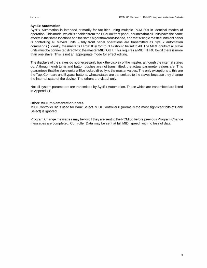
System Exclusive Message Descriptions
System Exclusive Message Header BlockAll SysEx messages are preceded by the standard header.
Byte # Byte Value Description Notes
1 F0 SysEx ID
2 06 Lexicon ID
3 07 PCM 80 ID
4 0iii iiii Device ID Values 0-126 are defined as specific addresses. Any mes-sage sent to device 127 will be received by any PCM 80 on thecable as long as it is enabled to receive System Exclusivemessages.
5 0iii iiii SysEx Identifier Identifies the type of message. All System Exclusive mes-sages in this document are described by this identifier. Iden-tifiers which are not used should be considered as reservedand should not be used.
6-(n-1) Message-specific bytes See individual descriptions
n F7 EOX End of exclusive
Table of SysEx IdentifiersThe following table provides a quick reference for the System Exclusive messages which are describedin detail in the following pages.
Identifier (Hex) Name of Message
0x00 System Configuration Response0x01 Bank Dump0x02 Single Effect Dump0x03 Table Dump0x04 Table Element Dump0x05 Chain Bulk Dump0x06 Single Chain Dump0x07 Chain Element Dump0x08 Display Dump
0x09-0x0A reserved0x0B Parameter Dump0x0C Button Dump
0x0D-0x11 reserved0x12 Soft Row Assignment Dump0x13 Patch Assignment Dump0x14 Knob Message0x15 Program Change Dump0x16 Parameter Specific Response0x17 Parameter Display Response0x18 System Setup Dump0x19 Save Current Edit Buffer Message0x1A Effect Info Response0x1B reserved0x1C Adjust Knob Name Dump0x1D reserved0x1E Verbose Dump Message0x1F LED Response0x20 Meter Response0x21 Patch Display Response0x22 Matrix Mapping Response0x23 Adjust Knob Value Dump0x24 Soft Row Display Response
0x25-0x7B reserved0x7C Failure Response
0x7D-0x7E reserved0x7F Data Request

5
PCM 80 Version 1.10 MIDI Implementation DetailsLexicon
0x00 System Configuration ResponseThis response is transmitted by the PCM 80 to a remote device when requested. It is ignored by the PCM80. Note that this is not a Setup Dump — it is purely informational.
Byte # Byte Value Description Notes1 F0 SysEx ID
2 06 Lexicon ID
3 07 PCM 80 ID
4 0iii iiii Device ID
5 0x0 Configuration Data
6 0iii iiii Major Version # This is the version number that appears to the left of the decimalpoint on the the integer portion of the power up display.
7 0iii iiii Minor Version # This is the version number that appears to the right of the decimalpoint on the fractional portion of the power up display. On the frontpanel this may be displayed as a 2-character value with a leadingzero. For example, a minor revison of 1 will appear as x.01. A minorrevision of 10 will appear as x.10
8-15 0iii iiii 8 Byte Time string Time of the code build in ASCII format xx:yy:zz(Hours:Minutes:Seconds)
16-26 0iii iiii 11 Byte Date string Date of the code build in ASCII format: xxx:yy:zzzz(Month:Day:Year)
27-34 0000 iiii 56000 memory page count4-byte value (nibble-ized) Number of pages (64K words/page) of memory available to the
Motorola 56002 processor. The number of pages in a standardPCM 80 is 4. Memory can be expanded using SIMM memory.
35-148 0iii iiii 114 Byte Bank information(Space for 57 banks) Indexed by bank, 2 characters/bank. First character=bank size.
(0=bank not present.) A non-zero in the second byte indicates thatthe bank is a non-writeable preset bank.
149 0n Card Present non-zero if present
150 0n Card Write Protect non-zero if protected
151 0iii iiii Card Version Indicates the version of the card directory structure. This should beignored if the Card Present bit is not set.
152 0iii iiii Card Type Types are:0x00=ROM (holds algorithms or presets)0x01=RAM (holds user effects, maps, setups and chains)0x80=Bootable Diagnostics card.This should be ignored if the Card Present bit is not set.
153-162 0iii iiii 10 Byte Name string for card This should be ignored if the Card Present bit is not set.
163 0iii iiii Page count Indicates the amount of memory available on the card. 1 page=64K.For example, 0x10 indicates 1 megabyte. This should be ignored ifthe Card Present bit is not set.
164 0iii iiii Count of algorithms online Number of valid algorithm IDs in the array beginning at byte 165.These are the algorithms currently available to the system andinclude internal algorithms plus any algorithms loaded from card.Algorithms for any card not loaded into the system will not appearhere.
165-228 0iii iiii 64 Byte List of algorithm IDs Only count from byte 164 is valid.
229 0iii iiii Current User Interface Mode 0=Control; 1=Tempo; 2=Edit; 3=Program; 4=Register. Mode andsubmode are purely informational and do not affect PCM 80 abilityto respond to MIDI.
230 0iii iiii User interface in a Submode 0=False; 1=True. A submode is defined as a state of the machinethat is different from that caused by pressing Control, Tempo, Edit,Program Banks or Register Banks. This includes any of the dialogmodes such as saving an Effect, etc.
231 0iii iiii Compare mode 0=Off, 1=On
232 0iii iiii Bypass 0=Off, 1=On
233 0xF7 End of SysEx
6
LexiconPCM 80 Version 1.10 MIDI Implementation Details
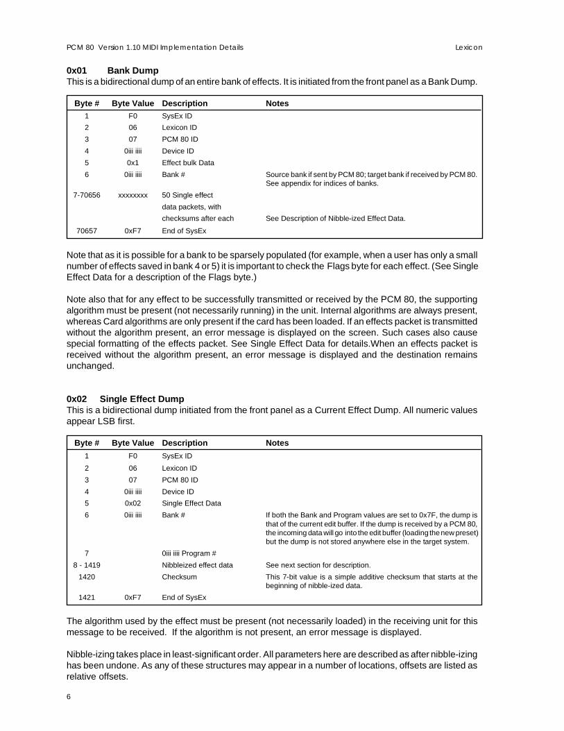
0x01 Bank DumpThis is a bidirectional dump of an entire bank of effects. It is initiated from the front panel as a Bank Dump.
Byte # Byte Value Description Notes1 F0 SysEx ID
2 06 Lexicon ID
3 07 PCM 80 ID
4 0iii iiii Device ID
5 0x1 Effect bulk Data
6 0iii iiii Bank # Source bank if sent by PCM 80; target bank if received by PCM 80.See appendix for indices of banks.
7-70656 xxxxxxxx 50 Single effect
data packets, with
checksums after each See Description of Nibble-ized Effect Data.
70657 0xF7 End of SysEx
Note that as it is possible for a bank to be sparsely populated (for example, when a user has only a smallnumber of effects saved in bank 4 or 5) it is important to check the Flags byte for each effect. (See SingleEffect Data for a description of the Flags byte.)
Note also that for any effect to be successfully transmitted or received by the PCM 80, the supportingalgorithm must be present (not necessarily running) in the unit. Internal algorithms are always present,whereas Card algorithms are only present if the card has been loaded. If an effects packet is transmittedwithout the algorithm present, an error message is displayed on the screen. Such cases also causespecial formatting of the effects packet. See Single Effect Data for details.When an effects packet isreceived without the algorithm present, an error message is displayed and the destination remainsunchanged.
0x02 Single Effect DumpThis is a bidirectional dump initiated from the front panel as a Current Effect Dump. All numeric valuesappear LSB first.
Byte # Byte Value Description Notes
1 F0 SysEx ID
2 06 Lexicon ID
3 07 PCM 80 ID
4 0iii iiii Device ID
5 0x02 Single Effect Data
6 0iii iiii Bank # If both the Bank and Program values are set to 0x7F, the dump isthat of the current edit buffer. If the dump is received by a PCM 80,the incoming data will go into the edit buffer (loading the new preset)but the dump is not stored anywhere else in the target system.
7 0iii iiii Program #
8 - 1419 Nibbleized effect data See next section for description.
1420 Checksum This 7-bit value is a simple additive checksum that starts at thebeginning of nibble-ized data.
1421 0xF7 End of SysEx
The algorithm used by the effect must be present (not necessarily loaded) in the receiving unit for thismessage to be received. If the algorithm is not present, an error message is displayed.
Nibble-izing takes place in least-significant order. All parameters here are described as after nibble-izinghas been undone. As any of these structures may appear in a number of locations, offsets are listed asrelative offsets.

7
PCM 80 Version 1.10 MIDI Implementation DetailsLexicon
Single Effect Data
ByteOffset Size Description Notes
0 16-bit (LSB first) Flags 0xffff=Valid Effect; 0xfffe=Blank effect slot. This is only sent during abank dump when certain positions in the bank are empty. Any other valueindicates that the effect was originally dumped from a Version 1.00 ROM.The internals of the dump differ from what is described here. Note thatthe version 1.10 ROM will accept effect dumps from Version 1.00 — theversion 1.00 ROM will NOT accept dumps from V1.10.
2 8-bit Algorithm ID The algorithm must be present in the unit for this packet to be transmittedor received. This packet has a special format if the algorithm is notpresent when the packet is transmitted. The value 0x7F replaces theAlgorithm ID which is placed in the Edit Matrix Position. The Effect Nameis properly transmitted, but the remainder of the packet is 0.
3 8-bit Edit Matrix Position Position in edit matrix when Edit is pressed. Upper nibble representscolumn; lower nibble represents row. See previous note in the case ofalgorithm not present.
4-15 12 Bytes Effect Name Name of effect. See notes on ASCII Character Data in the Overview.
16-24 9 Bytes Knob Name Name of Soft Knob. See notes on ASCII Character Data in the Overview.
25 1 Byte Adjust Knob Value Stored value for the Soft Knob.
26-35 10 Bytes Soft row assignments See Soft Row Assignment Dumps.
36-65 16-bit (LSB first)Type 2
Parameter Values Multiple values (15) This field is an indexed array of values for all Type 2 parameters. SeeAppendix G: Non-Patchable (Type 2) Parameters.
66-395 Set of 1103-Byte values Type 1 values (110) This field is an indexed array of values for all Type 1 parameters.
1 Byte=Tempo Flag (1 if Tempo Mode); 2 Bytes=Value.
If Tempo Mod =0, then this is a 16-bit value (LSB first). If Tempo Mode=1,then 1st byte is numerator and 2nd byte is denominator. The first 22parameters are the same for all algorithms. The remaining are unique foreach algorithm. See Appendix F: Patchable (Type 1) Parameters.
396 31 Bytes Patch Structure 0 This structure describes a single patch. Its fields are described in thePatch Save Data table following this section.
427 31 Bytes Patch Structure 1
458 31 Bytes Patch Structure 2
489 31 Bytes Patch Structure 3
520 31 Bytes Patch Structure 4
551 31 Bytes Patch Structure 5
582 31 Bytes Patch Structure 6
613 31 Bytes Patch Structure 7
644 31 Bytes Patch Structure 8
675 31 Bytes Patch Structure 9
706 End of Data End of Data End of Data

8
LexiconPCM 80 Version 1.10 MIDI Implementation Details
Patch Save Data
ByteOffset Size Description Notes
0 8-bit Valid Flag 0=patch not connected, ignore following data; 1=patch connected,following data valid.
1 8-bit Tempo Mode 0=Target parameter not in Tempo Mode; 1=Target parameter in TempoMode. This must match the tempo flag field for the Type 1 parameter thatis the target of the patch.
2 1 Byte Patch Source See the Patch Source Table in Appendix A.
3 1 Byte Destination List ID The value for the Destination List ID is returned by the ParameterSpecific Response (0x16).
4 2 Bytes (LSB first) Destination List Index The value for the Destination List Index is returned by the ParameterSpecific Response (0x16).
6 1 Byte Point Count 0-8=number of points in the patch. 0 is interpreted in the same way as aValid Flag of 0.
7 8 3-byte values Patch Point Values Values for each of 8 possible pivot points. Fields are interpreted as: 1Byte=Position (0-127). These should be in ascending order. 2Bytes=Value of target parameter at the pivot point. Only the first PointCount of these values is meaningful. The remainder should be transmit-ted as 0’s.
31 End of Data End of Data End of Data
0x03 Table DumpThis is a bidirectional dump (initiated from the front panel as a Map Dump) which describes a completeprogram table (map).
Byte # Byte Value Description Notes
1 F0 SysEx ID
2 06 Lexicon ID
3 07 PCM 80 ID
4 0iii iiii Device ID
5 0x3 Table Data
6 0iii iiii Table (map) # Unlike some other objects, there is no “current” table, so the 0x7F valuehas no function in this case. There are normally 2 tables in the box (0 and1). If a RAM card is in place, there are two additional tables (2 and 3).
7 0iii iiii Bank for tableposition 0 Any legitimate bank. See Appendix B: MIDI Bank Assignments. If
nothing is assigned to this position in the table, a value of 0x7F isreturned.
8 0iii iiii Offset for tableposition 0 0 - 49
9-262 Bank/offset for positions 1-127
263 0xF7 End of SysEx
9
PCM 80 Version 1.10 MIDI Implementation DetailsLexicon
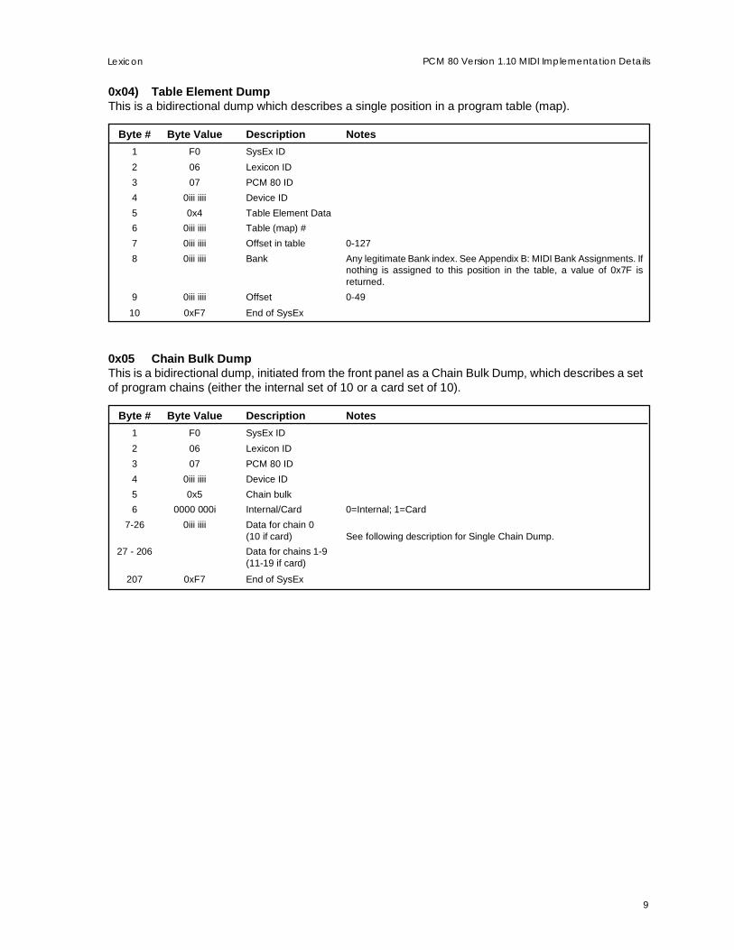
0x04) Table Element DumpThis is a bidirectional dump which describes a single position in a program table (map).
Byte # Byte Value Description Notes
1 F0 SysEx ID
2 06 Lexicon ID
3 07 PCM 80 ID
4 0iii iiii Device ID
5 0x4 Table Element Data
6 0iii iiii Table (map) #
7 0iii iiii Offset in table 0-127
8 0iii iiii Bank Any legitimate Bank index. See Appendix B: MIDI Bank Assignments. Ifnothing is assigned to this position in the table, a value of 0x7F isreturned.
9 0iii iiii Offset 0-49
10 0xF7 End of SysEx
0x05 Chain Bulk DumpThis is a bidirectional dump, initiated from the front panel as a Chain Bulk Dump, which describes a setof program chains (either the internal set of 10 or a card set of 10).
Byte # Byte Value Description Notes
1 F0 SysEx ID
2 06 Lexicon ID
3 07 PCM 80 ID
4 0iii iiii Device ID
5 0x5 Chain bulk
6 0000 000i Internal/Card 0=Internal; 1=Card
7-26 0iii iiii Data for chain 0(10 if card) See following description for Single Chain Dump.
27 - 206 Data for chains 1-9(11-19 if card)
207 0xF7 End of SysEx

10
LexiconPCM 80 Version 1.10 MIDI Implementation Details
0x06 Single Chain DumpThis is a bidirectional dump, initiated from the front panel as a Chain Dump, which describes a completeprogram chain.
Byte # Byte Value Description Notes
1 F0 SysEx ID
2 06 Lexicon ID
3 07 PCM 80 ID
4 0iii iiii Device ID
5 0x6 Chain Data
6 0iii iiii Chain # Unlike some other objects, there is no “current” chain, so the value 0x7Fhas no effect here. Normally there are 10 chains available (0-9). If a RAMcard is in place, an additional 10 chains (10-19) are available.
7 0iii iiii Bank for chainposition 0 Any legitimate Bank index. See Appendix B: MIDI Bank Assignments. If
nothing is assigned to this position in the table, a value of 0x7F isreturned.
8 0iii iiii Chain position offset 0-49
9-26 Bank/offset forpositions 1-9
27 0xF7 End of SysEx
0x07 Chain Element DumpThis is a bidirectional dump which describes a single position in a program chain.
Byte # Byte Value Description Notes1 F0 SysEx ID
2 06 Lexicon ID
3 07 PCM 80 ID
4 0iii iiii Device ID
5 0x7 Chain Element Data
6 0iii iiii Chain #
7 0iii iiii Offset in chain 0-9
8 0iii iiii Bank Any legitimate Bank index. See Appendix B: MIDI Bank Assignments. Ifnothing is assigned to this position in the table, a value of 0x7F isreturned.
9 0iii iiii Offset 0-49
10 0xF7 End of SysEx
0x08 Display DumpWhen sent from the PCM 80, this bidirectional dump holds the current display information, whatever itis. When sent to the PCM 80, this text is displayed for 2 seconds.
Byte # Byte Value Description Notes1 F0 SysEx ID
2 06 Lexicon ID
3 07 PCM 80 ID
4 0iii iiii Device ID
5 0x08 Display message
6-25 0iii iiii Top line of display 20-byte copy of upper display line.
26-45 0iii iiii Bottom line of display 20-byte copy of lower display line.
46 0xF7 End of SysEx
11
PCM 80 Version 1.10 MIDI Implementation DetailsLexicon
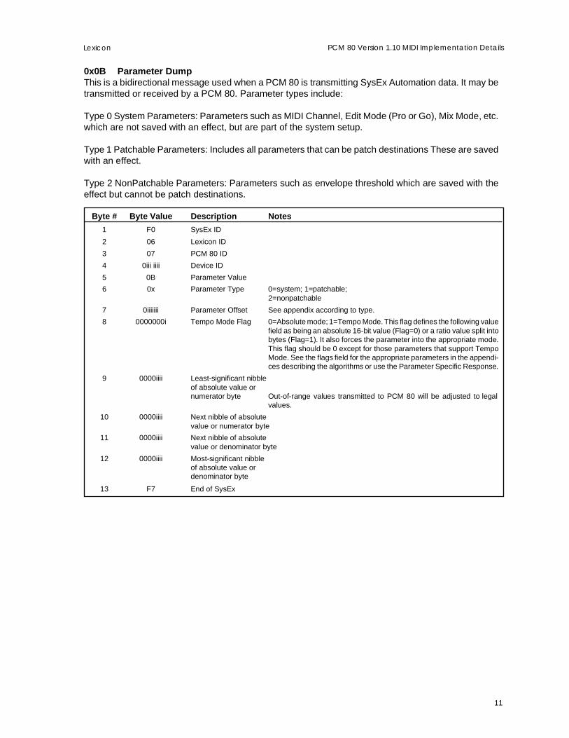
0x0B Parameter DumpThis is a bidirectional message used when a PCM 80 is transmitting SysEx Automation data. It may betransmitted or received by a PCM 80. Parameter types include:
Type 0 System Parameters: Parameters such as MIDI Channel, Edit Mode (Pro or Go), Mix Mode, etc.which are not saved with an effect, but are part of the system setup.
Type 1 Patchable Parameters: Includes all parameters that can be patch destinations These are savedwith an effect.
Type 2 NonPatchable Parameters: Parameters such as envelope threshold which are saved with theeffect but cannot be patch destinations.
Byte # Byte Value Description Notes
1 F0 SysEx ID
2 06 Lexicon ID
3 07 PCM 80 ID
4 0iii iiii Device ID
5 0B Parameter Value
6 0x Parameter Type 0=system; 1=patchable;2=nonpatchable
7 0iiiiiii Parameter Offset See appendix according to type.
8 0000000i Tempo Mode Flag 0=Absolute mode; 1=Tempo Mode. This flag defines the following valuefield as being an absolute 16-bit value (Flag=0) or a ratio value split intobytes (Flag=1). It also forces the parameter into the appropriate mode.This flag should be 0 except for those parameters that support TempoMode. See the flags field for the appropriate parameters in the appendi-ces describing the algorithms or use the Parameter Specific Response.
9 0000iiii Least-significant nibbleof absolute value ornumerator byte Out-of-range values transmitted to PCM 80 will be adjusted to legal
values.
10 0000iiii Next nibble of absolutevalue or numerator byte
11 0000iiii Next nibble of absolutevalue or denominator byte
12 0000iiii Most-significant nibbleof absolute value ordenominator byte
13 F7 End of SysEx
12
LexiconPCM 80 Version 1.10 MIDI Implementation Details
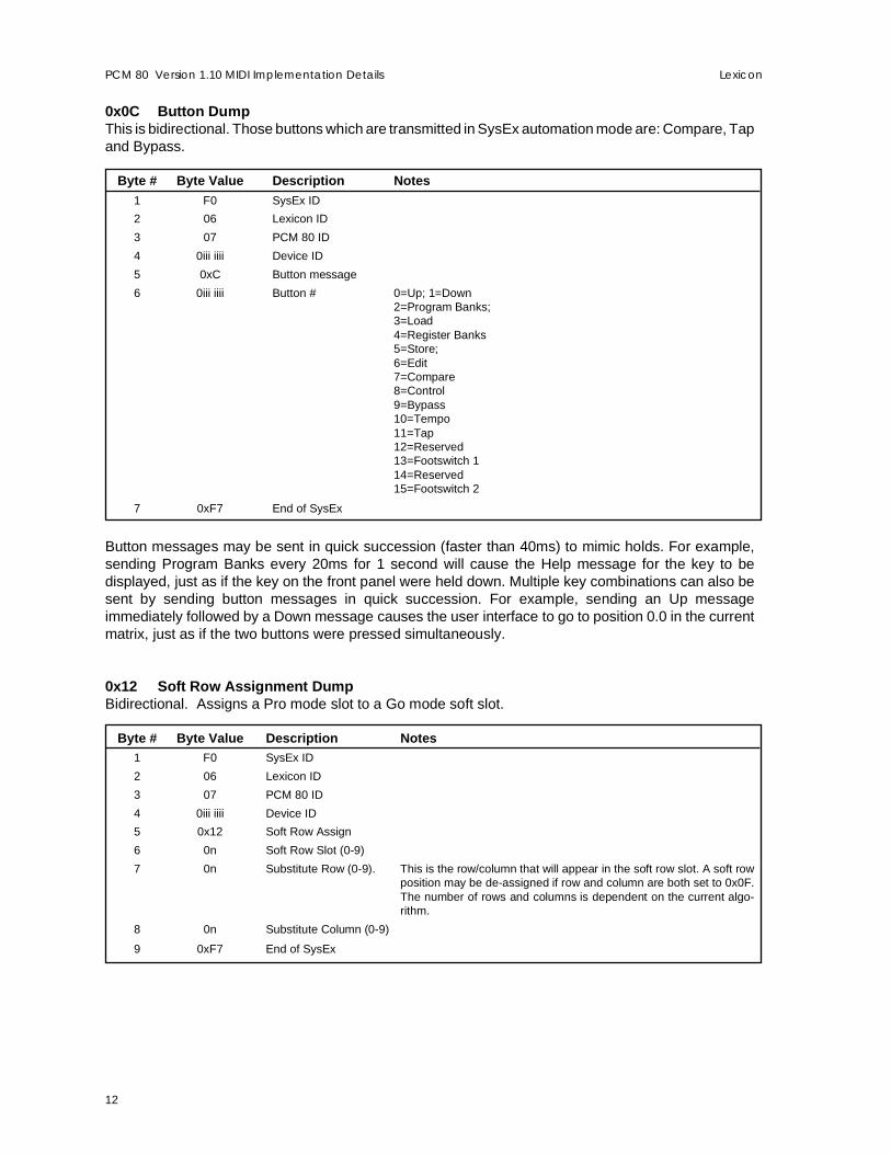
0x0C Button DumpThis is bidirectional. Those buttons which are transmitted in SysEx automation mode are: Compare, Tapand Bypass.
Byte # Byte Value Description Notes1 F0 SysEx ID
2 06 Lexicon ID
3 07 PCM 80 ID
4 0iii iiii Device ID
5 0xC Button message
6 0iii iiii Button # 0=Up; 1=Down2=Program Banks;3=Load4=Register Banks5=Store;6=Edit7=Compare8=Control9=Bypass10=Tempo11=Tap12=Reserved13=Footswitch 114=Reserved15=Footswitch 2
7 0xF7 End of SysEx
Button messages may be sent in quick succession (faster than 40ms) to mimic holds. For example,sending Program Banks every 20ms for 1 second will cause the Help message for the key to bedisplayed, just as if the key on the front panel were held down. Multiple key combinations can also besent by sending button messages in quick succession. For example, sending an Up messageimmediately followed by a Down message causes the user interface to go to position 0.0 in the currentmatrix, just as if the two buttons were pressed simultaneously.
0x12 Soft Row Assignment DumpBidirectional. Assigns a Pro mode slot to a Go mode soft slot.
Byte # Byte Value Description Notes1 F0 SysEx ID
2 06 Lexicon ID
3 07 PCM 80 ID
4 0iii iiii Device ID
5 0x12 Soft Row Assign
6 0n Soft Row Slot (0-9)
7 0n Substitute Row (0-9). This is the row/column that will appear in the soft row slot. A soft rowposition may be de-assigned if row and column are both set to 0x0F.The number of rows and columns is dependent on the current algo-rithm.
8 0n Substitute Column (0-9)
9 0xF7 End of SysEx
13
PCM 80 Version 1.10 MIDI Implementation DetailsLexicon
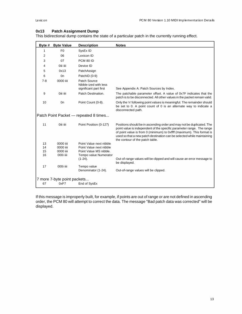
0x13 Patch Assignment DumpThis bidirectional dump contains the state of a particular patch in the currently running effect.
Byte # Byte Value Description Notes1 F0 SysEx ID
2 06 Lexicon ID
3 07 PCM 80 ID
4 0iii iiii Device ID
5 0x13 PatchAssign
6 0n PatchID (0-9)
7-8 0000 iiii Patch SourceNibble-ized with lesssignificant part first See Appendix A: Patch Sources by Index.
9 0iii iiii Patch Destination. The patchable parameter offset. A value of 0x7F indicates that thepatch is to be disconnected. All other values in the packet remain valid.
10 0n Point Count (0-8). Only the 'n' following point values is meaningful. The remainder shouldbe set to 0. A point count of 0 is an alternate way to indicate adisconnected path.
Patch Point Packet — repeated 8 times...
11 0iii iiii Point Position (0-127) Positions should be in ascending order and may not be duplicated. Thepoint value is independent of the specific parameter range. The rangeof point value is from 0 (minimum) to 0xffff (maximum). This format isused so that a new patch destination can be selected while maintainingthe contour of the patch table.
13 0000 iiii Point Value next nibble14 0000 iiii Point Value next nibble15 0000 iiii Point Value MS nibble.16 000i iiii Tempo value Numerator
(1-24). Out-of-range values will be clipped and will cause an error message tobe displayed.
17 000i iiii Tempo valueDenominator (1-24). Out-of-range values will be clipped.
7 more 7-byte point packets...67 0xF7 End of SysEx
If this message is improperly built, for example, if points are out of range or are not defined in ascendingorder, the PCM 80 will attempt to correct the data. The message "Bad patch data was corrected" will bedisplayed.

14
LexiconPCM 80 Version 1.10 MIDI Implementation Details
0x14 Knob MessageHost to PCM 80 only. (In SysEx Automation mode, the PCM 80 sends parameter values, not knobmessages.) Knobs operate within the current context of the user interface. For example, in RegisterBanks mode, the Adjust knob is a soft knob. In Edit mode, it adjusts the displayed parameter. Thismessage is only useful for a remote controller.
Byte # Byte Value Description Notes1 F0 SysEx ID
2 06 Lexicon ID
3 07 PCM 80 ID
4 0iii iiii Device ID
5 0x14 Knob Code
6 0n Knob ID: 0=Select knob; 1=Adjust knob
7 0n Least-significantnibble of 2’scomplement knobdelta (16 bits). For example: 0xffff=-1 (counterclockwise); 0x0001=+1 (clockwise)
8 0n Next nibble
9 0n Next nibble
10 0n Most-significant nibble
11 0xF7 End of SysEx
0x15 Program Change DumpBidirectional. This is the method used in SysEx Automation to send Program Change messages. It maybe used in other cases, although the number of bytes is larger than a standard MIDI Program Changemessage. The current MIDI Program Change mode selection (mapped, chained, off, etc) is ignored.
Byte # Byte Value Description Notes1 F0 SysEx ID
2 06 Lexicon ID
3 07 PCM 80 ID
4 0iii iiii Device ID
5 0x15 Program Change code
6 0iii iiii Bank See Appendix B: MIDI Bank Assignments.
7 0iii iiii Program 0-49
8 0xF7 End of SysEx
15
PCM 80 Version 1.10 MIDI Implementation DetailsLexicon
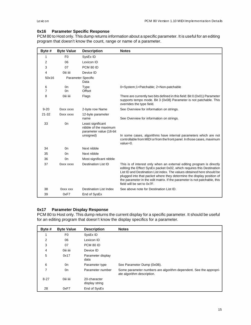
0x16 Parameter Specific ResponsePCM 80 to Host only. This dump returns information about a specific parameter. It is useful for an editingprogram that doesn’t know the count, range or name of a parameter.
Byte # Byte Value Description Notes
1 F0 SysEx ID
2 06 Lexicon ID
3 07 PCM 80 ID
4 0iii iiii Device ID
5 0x16 Parameter SpecificData
6 0n Type 0=System;1=Patchable; 2=Non-patchable7 0n Offset
8 0iii iiii Flags There are currently two bits defined in this field: Bit 0 (0x01) Parametersupports tempo mode. Bit 3 (0x08) Parameter is not patchable. Thisoverrides the type field.
9-20 0xxx xxxx 2-byte row Name See Overview for information on strings.
21-32 0xxx xxxx 12-byte parametername See Overview for information on strings.
33 0n Least significantnibble of the maximumparameter value (16-bitunsigned) In some cases, algorithms have internal parameters which are not
controllable from MIDI or from the front panel. In those cases, maximumvalue=0.
34 0n Next nibble
35 0n Next nibble
36 0n Most-significant nibble
37 0xxx xxxx Destination List ID This is of interest only when an external editing program is directlyediting the Effect SysEx packet 0x02, which requires this DestinationList ID and Destination List index. The values obtained here should beplugged into that packet where they determine the display position ofthe parameter in the edit matrix. If the parameter is not patchable, thisfield will be set to 0x7F.
38 0xxx xxx Destination List Index See above note for Destination List ID.
39 0xF7 End of SysEx
0x17 Parameter Display ResponsePCM 80 to Host only. This dump returns the current display for a specific parameter. It should be usefulfor an editing program that doesn’t know the display specifics for a parameter.
Byte # Byte Value Description Notes1 F0 SysEx ID
2 06 Lexicon ID
3 07 PCM 80 ID
4 0iii iiii Device ID
5 0x17 Parameter displaydata
6 0n Parameter type See Parameter Dump (0x0B).
7 0n Parameter number Some parameter numbers are algorithm dependent. See the appropri-ate algorithm description.
8-27 0iii iiii 20-characterdisplay string
28 0xF7 End of SysEx
16
LexiconPCM 80 Version 1.10 MIDI Implementation Details
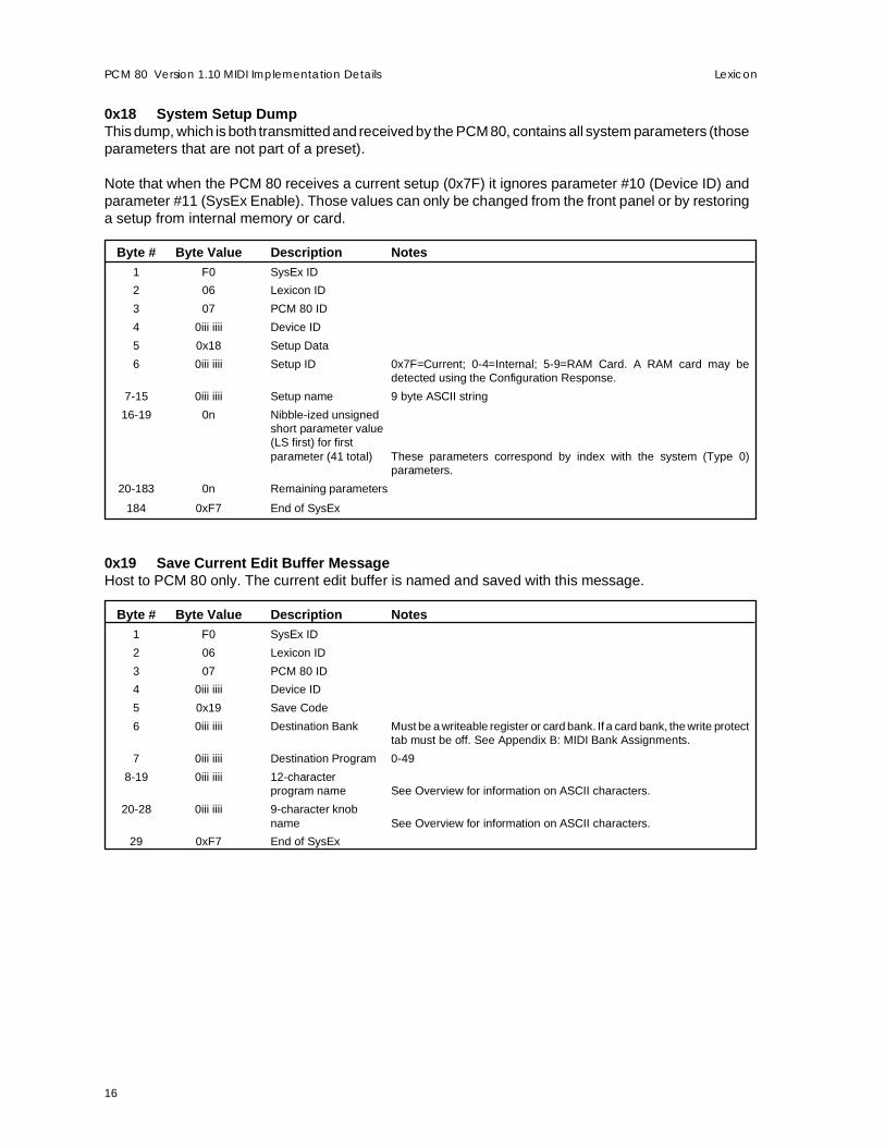
0x18 System Setup DumpThis dump, which is both transmitted and received by the PCM 80, contains all system parameters (thoseparameters that are not part of a preset).
Note that when the PCM 80 receives a current setup (0x7F) it ignores parameter #10 (Device ID) andparameter #11 (SysEx Enable). Those values can only be changed from the front panel or by restoringa setup from internal memory or card.
Byte # Byte Value Description Notes1 F0 SysEx ID
2 06 Lexicon ID
3 07 PCM 80 ID
4 0iii iiii Device ID
5 0x18 Setup Data
6 0iii iiii Setup ID 0x7F=Current; 0-4=Internal; 5-9=RAM Card. A RAM card may bedetected using the Configuration Response.
7-15 0iii iiii Setup name 9 byte ASCII string
16-19 0n Nibble-ized unsignedshort parameter value(LS first) for firstparameter (41 total) These parameters correspond by index with the system (Type 0)
parameters.
20-183 0n Remaining parameters
184 0xF7 End of SysEx
0x19 Save Current Edit Buffer MessageHost to PCM 80 only. The current edit buffer is named and saved with this message.
Byte # Byte Value Description Notes1 F0 SysEx ID
2 06 Lexicon ID
3 07 PCM 80 ID
4 0iii iiii Device ID
5 0x19 Save Code
6 0iii iiii Destination Bank Must be a writeable register or card bank. If a card bank, the write protecttab must be off. See Appendix B: MIDI Bank Assignments.
7 0iii iiii Destination Program 0-49
8-19 0iii iiii 12-characterprogram name See Overview for information on ASCII characters.
20-28 0iii iiii 9-character knobname See Overview for information on ASCII characters.
29 0xF7 End of SysEx
17
PCM 80 Version 1.10 MIDI Implementation DetailsLexicon
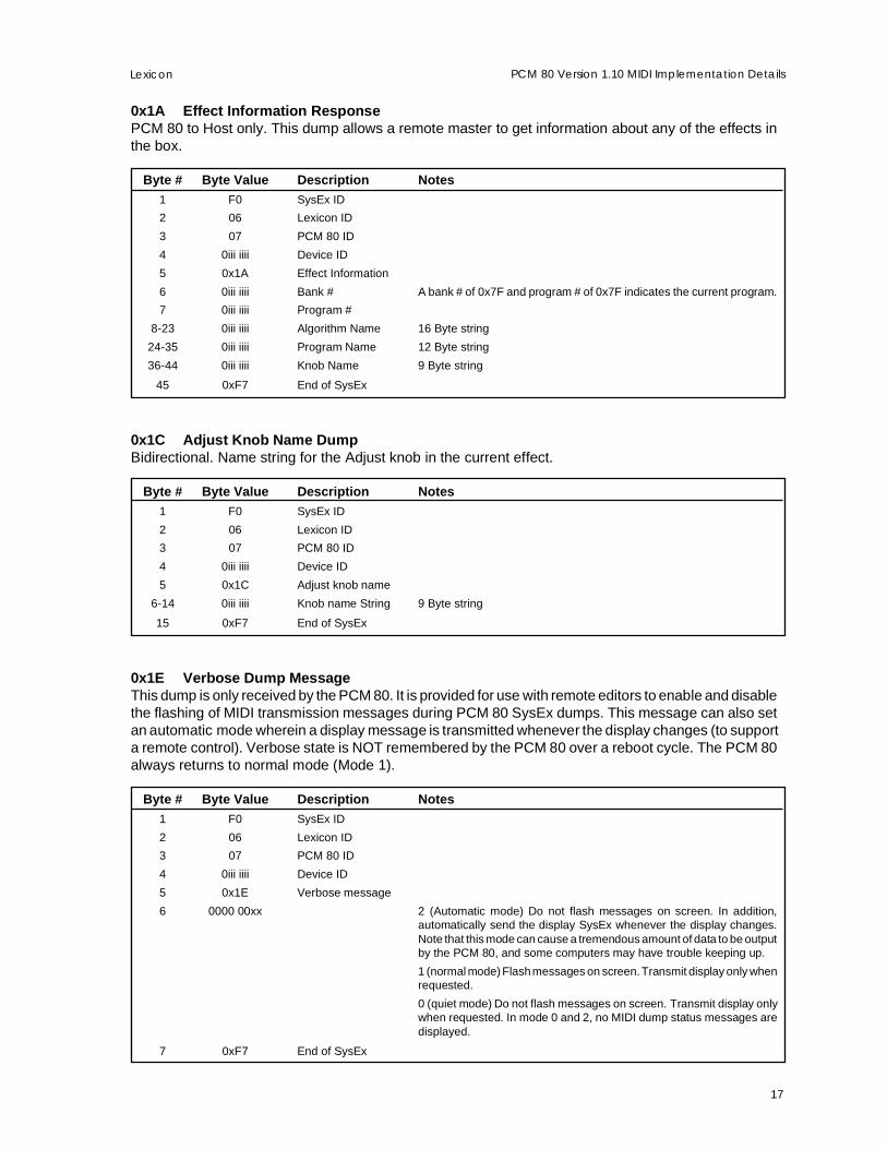
0x1A Effect Information ResponsePCM 80 to Host only. This dump allows a remote master to get information about any of the effects inthe box.
Byte # Byte Value Description Notes1 F0 SysEx ID
2 06 Lexicon ID
3 07 PCM 80 ID
4 0iii iiii Device ID
5 0x1A Effect Information
6 0iii iiii Bank # A bank # of 0x7F and program # of 0x7F indicates the current program.
7 0iii iiii Program #
8-23 0iii iiii Algorithm Name 16 Byte string
24-35 0iii iiii Program Name 12 Byte string
36-44 0iii iiii Knob Name 9 Byte string
45 0xF7 End of SysEx
0x1C Adjust Knob Name DumpBidirectional. Name string for the Adjust knob in the current effect.
Byte # Byte Value Description Notes1 F0 SysEx ID
2 06 Lexicon ID
3 07 PCM 80 ID
4 0iii iiii Device ID
5 0x1C Adjust knob name
6-14 0iii iiii Knob name String 9 Byte string
15 0xF7 End of SysEx
0x1E Verbose Dump MessageThis dump is only received by the PCM 80. It is provided for use with remote editors to enable and disablethe flashing of MIDI transmission messages during PCM 80 SysEx dumps. This message can also setan automatic mode wherein a display message is transmitted whenever the display changes (to supporta remote control). Verbose state is NOT remembered by the PCM 80 over a reboot cycle. The PCM 80always returns to normal mode (Mode 1).
Byte # Byte Value Description Notes1 F0 SysEx ID
2 06 Lexicon ID
3 07 PCM 80 ID
4 0iii iiii Device ID
5 0x1E Verbose message
6 0000 00xx 2 (Automatic mode) Do not flash messages on screen. In addition,automatically send the display SysEx whenever the display changes.Note that this mode can cause a tremendous amount of data to be outputby the PCM 80, and some computers may have trouble keeping up.
1 (normal mode) Flash messages on screen. Transmit display only whenrequested.
0 (quiet mode) Do not flash messages on screen. Transmit display onlywhen requested. In mode 0 and 2, no MIDI dump status messages aredisplayed.
7 0xF7 End of SysEx

18
LexiconPCM 80 Version 1.10 MIDI Implementation Details
0x1F LED responseWhen the automatic verbose mode is selected, this dump is transmitted by the PCM 80 whenever anyof the LEDs change. The meter values are also included, since it is likely that they have also changed.When this message is sent, no meter message is sent for the same time period to lower the data traffic.
Byte # Byte Value Description Notes1 F0 SysEx ID
2 06 Lexicon ID
3 07 PCM 80 ID
4 0iii iiii Device ID
5 0x1F LED message
6 0iii iiii LED bitmask Bit 0=Program Banks; Bit 1=Load; Bit 2=Register Banks; Bit 3=Store;Bit 4=Edit; Bit 5=Compare; Bit 6=Control
7 0iii iiii LED bitmask Bit 0=Bypass; Bit 1=Tempo; Bits 2-6=reserved
8 000i iiii Left Meter bitmask These bits match the front panel meters as follows: Bit 0 =24dB (green);Bit 1=18dB (green); Bit 2=2dB (green); Bit 3=6dB (amber); Bit 4=0dB(red)
9 000i iiii Right Meter bitmask same as left meter bitmask
10 0xF7 End of SysEx
0x20 Meter responseWhen the automatic verbose mode is selected, this dump is transmitted by the PCM 80 whenever themeter values change. For data reduction purposes, there is no LED change.
Byte # Byte Value Description Notes1 F0 SysEx ID
2 06 Lexicon ID
3 07 PCM 80 ID
4 0iii iiii Device ID
5 0x20 Meter message
6 000i iiii Left Meter bitmask Same as the LED message description.
7 000i iiii Right Meter bitmask
8 0xF7 End of SysEx

19
PCM 80 Version 1.10 MIDI Implementation DetailsLexicon
0x21 Patch Display ResponsePCM 80 to Host only. This dump returns the current display for a specified patch at a specified input value.It is useful for an editing program that doesn’t know the display specifics for a parameter.
Byte # Byte Value Description Notes
1 F0 SysEx ID
2 06 Lexicon ID
3 07 PCM 80 ID
4 0iii iiii Device ID
5 0x21 Patch display data
6 0n Patch (0-9)
7 0n Pivot point (0-127) This should be an assigned point.
8-22 0iii iiii 15-characterdisplay string See Overview for information on ASCII characters.
23 0xF7 End of SysEx
0x22 Matrix Mapping ResponsePCM 80 to Host only. This dump is a response to a request for information. The request holds DestinationList ID and Destination List Index. This message returns the parameter that is mapped to that locationin the edit matrix. These are required when translating to and from the stored effect format.
Byte # Byte Value Description Notes1 F0 SysEx ID
2 06 Lexicon ID
3 07 PCM 80 ID
4 0iii iiii Device ID
5 0x22 matrix mapping data
6 0iii iiii Destination List ID Used in the single effect packet.
7 0iii iiii Destination List Index Used in the single effect packet.
8 0iii iiii Parameter type See Parameter Dump .
9 0iii iiii Parameter offset Dependent on parameter type and algorithm.
10 0xF7 End of SysEx
0x23 Adjust Knob Value DumpBidirectional. This dump allows the Adjust knob value to be transmitted or received.
Byte # Byte Value Description Notes1 F0 SysEx ID
2 06 Lexicon ID
3 07 PCM 80 ID
4 0iii iiii Device ID
5 0x23 Adjust knob value
6 0iii iiii Knob Value Value within range of 0-127
7 0xF7 End of SysEx
20
LexiconPCM 80 Version 1.10 MIDI Implementation Details
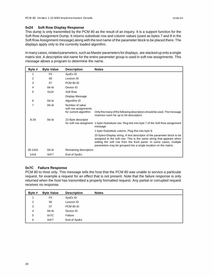
0x24 Soft Row Display ResponseThis dump is only transmitted by the PCM 80 as the result of an inquiry. It is a support function for theSoft Row Assignment Dump. It returns substitute row and column values (used as bytes 7 and 8 in theSoft Row Assignment message) along with the text name of the parameter block to be placed there. Thedisplays apply only to the currently loaded algorithm.
In many cases, related parameters, such as Master parameters for displays, are stacked up onto a singlematrix slot. A descriptive slot name for the entire parameter group is used in soft row assignments. Thismessage allows a program to determine the name.
Byte # Byte Value Description Notes1 F0 SysEx ID
2 06 Lexicon ID
3 07 PCM 80 ID
4 0iii iiii Device ID
5 0x24 Soft Row
Display Message
6 0iii iiii Algorithm iD
7 0iii iiii Number of valuesoft row assignmentsfor current algorithm Only this many of the following descriptors should be used. The message
reserves room for up to 64 descriptors
8-29 0iii iiii 22-Byte descriptorfor soft row assigment 1 byte=Substitute row. Plug this into byte 7 of the Soft Row assignment
message
1 byte=Substitute column. Plug this into byte 8.
20 bytes=Display string. A text descriptor of the parameter block to beassigned to the soft row. This is the same string that appears whenediting the soft row from the front panel. In some cases, multipleparameters may be grouped into a single location on the matrix.
30-1415 0iii iiii Remaining descriptors
1416 0xF7 End of SysEx
0x7C Failure ResponsePCM 80 to Host only. This message tells the host that the PCM 80 was unable to service a particularrequest, for example a request for an effect that is not present. Note that the failure response is onlyreturned when the host has transmitted a properly formatted request. Any partial or corrupted requestreceives no response.
Byte # Byte Value Description Notes1 F0 SysEx ID
2 06 Lexicon ID
3 07 PCM 80 ID
4 0iii iiii Device ID
5 0x7C Failure
6 0xF7 End of SysEx

21
PCM 80 Version 1.10 MIDI Implementation DetailsLexicon
0x7F Data RequestHost to PCM 80 only. The host may request that a message be sent by the PCM 80.
Byte # Byte Value Description Notes1 F0 SysEx ID
2 06 Lexicon ID
3 07 PCM 80 ID
4 0iii iiii Device ID
5 0x7F Data request
6 0iii iiii Type of datarequested This matches the message IDs described above, but not all messages
may be requested. See the table below
7-11 parameters forrequest These depend on the type of message requested. Any unused param-
eters should be set to 0. See the table below
12 0xF7 End of SysEx
Request Request Byte Parameter bytes NotesSystemConfig 0x00 none
Effect Bulk 0x01 Bank
Effect Single 0x02 Bank, Offset 0x7F returns dump of currently-running effect, including any unsavededits.
Table 0x03 Table ID
Tableelement 0x04 Table ID, Offset
Chain Bulk 0x05 Chain Group 0=Internal; 1=External (Card)
Chain 0x06 Chain ID
Chain element 0x07 Chain ID, Offset
Display 0x08 none Return dump of current display.
Parameter 0x0B Type, Offset Dependent on parameter type and algorithm.
Soft Row 0x12 Offset (0-9) Return matrix positions mapped to specified soft row offset.
Patch 0x13 PatchID (0-9)
Param spec 0x16 Type, Offset
Param display 0x17 Type, Offset
Effect Info 0x1A Bank, Offset Offset must be 0-49.
0x1B Bank
Adjust Name 0x1C none
0x1D
Patch Display 0x21 Patch#, Pivot Point
Matrix Mapping 0x22 Destination List ID,Destination List Index
Adjust Value 0x23 none
Soft RowDisplay 0x24 Algorithm ID 0x7F for currently running algorithm
22
LexiconPCM 80 Version 1.10 MIDI Implementation Details
PCM 80 Algorithms
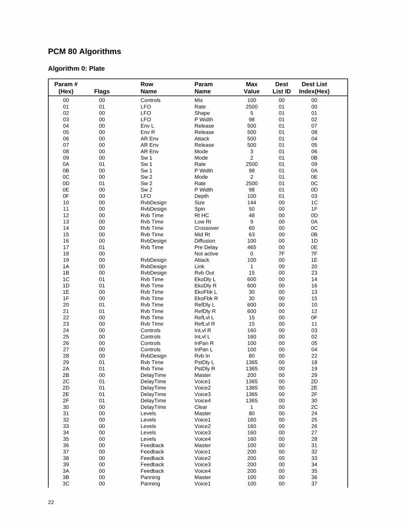
Algorithm 0: Plate
Param # Row Param Max Dest Dest List(Hex) Flags Name Name Value List ID Index(Hex)
00 00 Controls Mix 100 00 0001 01 LFO Rate 2500 01 0002 00 LFO Shape 5 01 0103 00 LFO P Width 98 01 0204 00 Env L Release 500 01 0705 00 Env R Release 500 01 0806 00 AR Env Attack 500 01 0407 00 AR Env Release 500 01 0508 00 AR Env Mode 3 01 0609 00 Sw 1 Mode 2 01 0B0A 01 Sw 1 Rate 2500 01 090B 00 Sw 1 P Width 98 01 0A0C 00 Sw 2 Mode 2 01 0E0D 01 Sw 2 Rate 2500 01 0C0E 00 Sw 2 P Width 98 01 0D0F 00 LFO Depth 100 01 0310 00 RvbDesign Size 144 00 1C11 00 RvbDesign Spin 50 00 1F12 00 Rvb Time Rt HC 48 00 0D13 00 Rvb Time Low Rt 9 00 0A14 00 Rvb Time Crossover 60 00 0C15 00 Rvb Time Mid Rt 63 00 0B16 00 RvbDesign Diffusion 100 00 1D17 01 Rvb Time Pre Delay 465 00 0E18 00 Not active 0 7F 7F19 00 RvbDesign Attack 100 00 1E1A 00 RvbDesign Link 1 00 201B 00 RvbDesign Rvb Out 15 00 231C 01 Rvb Time EkoDly L 600 00 141D 01 Rvb Time EkoDly R 600 00 161E 00 Rvb Time EkoFbk L 30 00 131F 00 Rvb Time EkoFbk R 30 00 1520 01 Rvb Time RefDly L 600 00 1021 01 Rvb Time RefDly R 600 00 1222 00 Rvb Time RefLvl L 15 00 0F23 00 Rvb Time RefLvl R 15 00 1124 00 Controls InLvl R 160 00 0325 00 Controls InLvl L 160 00 0226 00 Controls InPan R 100 00 0527 00 Controls InPan L 100 00 0428 00 RvbDesign Rvb In 80 00 2229 01 Rvb Time PstDly L 1365 00 182A 01 Rvb Time PstDly R 1365 00 192B 00 DelayTime Master 200 00 292C 01 DelayTime Voice1 1365 00 2D2D 01 DelayTime Voice2 1365 00 2E2E 01 DelayTime Voice3 1365 00 2F2F 01 DelayTime Voice4 1365 00 3030 00 DelayTime Clear 1 00 2C31 00 Levels Master 80 00 2432 00 Levels Voice1 160 00 2533 00 Levels Voice2 160 00 2634 00 Levels Voice3 160 00 2735 00 Levels Voice4 160 00 2836 00 Feedback Master 100 00 3137 00 Feedback Voice1 200 00 3238 00 Feedback Voice2 200 00 3339 00 Feedback Voice3 200 00 343A 00 Feedback Voice4 200 00 353B 00 Panning Master 100 00 363C 00 Panning Voice1 100 00 37

23
Lexicon PCM 80 Version 1.10 MIDI Implementation Details
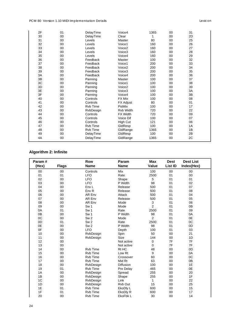
3D 00 Panning Voice2 100 00 383E 00 Panning Voice3 100 00 393F 00 Panning Voice4 100 00 3A40 00 Controls FX Mix 100 00 0841 00 Controls FX Adjust 80 00 0142 00 Rvb Time PstMix 100 00 1743 00 RvbDesign Rvb Width 720 00 2144 00 Controls FX Width 720 00 0945 00 Controls Voice Dif 100 00 0746 00 Controls High Cut 121 00 0647 00 Rvb Time GldResp 100 00 1A48 00 Rvb Time GldRange 1365 00 1B49 00 DelayTime GldResp 100 00 2A4A 00 DelayTime GldRange 1365 00 2B
Algorithm 1: Chamber
Param # Row Param Max Dest Dest List(Hex) Flags Name Name Value List ID Index(Hex)
00 00 Controls Mix 100 00 0001 01 LFO Rate 2500 01 0002 00 LFO Shape 5 01 0103 00 LFO P Width 98 01 0204 00 Env L Release 500 01 0705 00 Env R Release 500 01 0806 00 AR Env Attack 500 01 0407 00 AR Env Release 500 01 0508 00 AR Env Mode 3 01 0609 00 Sw 1 Mode 2 01 0B0A 01 Sw 1 Rate 2500 01 090B 00 Sw 1 P Width 98 01 0A0C 00 Sw 2 Mode 2 01 0E0D 01 Sw 2 Rate 2500 01 0C0E 00 Sw 2 P Width 98 01 0D0F 00 LFO Depth 100 01 0310 00 RvbDesign Size 144 00 1C11 00 RvbDesign Spin 50 00 2012 00 Rvb Time Rt HC 48 00 0D13 00 Rvb Time Low Rt 9 00 0A14 00 Rvb Time Crossover 60 00 0C15 00 Rvb Time Mid Rt 63 00 0B16 00 RvbDesign Diffusion 100 00 1D17 01 Rvb Time Pre Delay 465 00 0E18 00 RvbDesign Spread 255 00 1F19 00 RvbDesign Shape 255 00 1E1A 00 RvbDesign Link 1 00 211B 00 RvbDesign Rvb Out 15 00 241C 01 Rvb Time EkoDly L 600 00 141D 01 Rvb Time EkoDly R 600 00 161E 00 Rvb Time EkoFbk L 30 00 131F 00 Rvb Time EkoFbk R 30 00 1520 01 Rvb Time RefDly L 600 00 1021 01 Rvb Time RefDly R 600 00 1222 00 Rvb Time RefLvl L 15 00 0F23 00 Rvb Time RefLvl R 15 00 1124 00 Controls InLvl R 160 00 0325 00 Controls InLvl L 160 00 0226 00 Controls InPan R 100 00 0527 00 Controls InPan L 100 00 0428 00 RvbDesign Rvb In 80 00 2329 01 Rvb Time PstDly L 1365 00 182A 01 Rvb Time PstDly R 1365 00 192B 00 DelayTime Master 200 00 2A2C 01 DelayTime Voice1 1365 00 2E2D 01 DelayTime Voice2 1365 00 2F2E 01 DelayTime Voice3 1365 00 30
24
LexiconPCM 80 Version 1.10 MIDI Implementation Details
2F 01 DelayTime Voice4 1365 00 3130 00 DelayTime Clear 1 00 2D31 00 Levels Master 80 00 2532 00 Levels Voice1 160 00 2633 00 Levels Voice2 160 00 2734 00 Levels Voice3 160 00 2835 00 Levels Voice4 160 00 2936 00 Feedback Master 100 00 3237 00 Feedback Voice1 200 00 3338 00 Feedback Voice2 200 00 3439 00 Feedback Voice3 200 00 353A 00 Feedback Voice4 200 00 363B 00 Panning Master 100 00 373C 00 Panning Voice1 100 00 383D 00 Panning Voice2 100 00 393E 00 Panning Voice3 100 00 3A3F 00 Panning Voice4 100 00 3B40 00 Controls FX Mix 100 00 0841 00 Controls FX Adjust 80 00 0142 00 Rvb Time PstMix 100 00 1743 00 RvbDesign Rvb Width 720 00 2244 00 Controls FX Width 720 00 0945 00 Controls Voice Dif 100 00 0746 00 Controls High Cut 121 00 0647 00 Rvb Time GldResp 100 00 1A48 00 Rvb Time GldRange 1365 00 1B49 00 DelayTime GldResp 100 00 2B4A 00 DelayTime GldRange 1365 00 2C
Algorithm 2: Infinite
Param # Row Param Max Dest Dest List(Hex) Flags Name Name Value List ID Index(Hex)
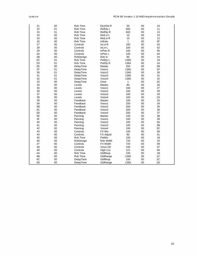
00 00 Controls Mix 100 00 0001 01 LFO Rate 2500 01 0002 00 LFO Shape 5 01 0103 00 LFO P Width 98 01 0204 00 Env L Release 500 01 0705 00 Env R Release 500 01 0806 00 AR Env Attack 500 01 0407 00 AR Env Release 500 01 0508 00 AR Env Mode 3 01 0609 00 Sw 1 Mode 2 01 0B0A 01 Sw 1 Rate 2500 01 090B 00 Sw 1 P Width 98 01 0A0C 00 Sw 2 Mode 2 01 0E0D 01 Sw 2 Rate 2500 01 0C0E 00 Sw 2 P Width 98 01 0D0F 00 LFO Depth 100 01 0310 00 RvbDesign Spin 50 00 2111 00 RvbDesign Size 144 00 1D12 00 Not active 0 7F 7F13 00 Not active 0 7F 7F14 00 Rvb Time Rt HC 48 00 0D15 00 Rvb Time Low Rt 9 00 0A16 00 Rvb Time Crossover 60 00 0C17 00 Rvb Time Mid Rt 63 00 0B18 00 RvbDesign Diffusion 100 00 1E19 01 Rvb Time Pre Delay 465 00 0E1A 00 RvbDesign Spread 255 00 201B 00 RvbDesign Shape 255 00 1F1C 00 RvbDesign Link 1 00 221D 00 RvbDesign Rvb Out 15 00 251E 01 Rvb Time EkoDly L 600 00 151F 01 Rvb Time EkoDly R 600 00 1720 00 Rvb Time EkoFbk L 30 00 14
25
Lexicon PCM 80 Version 1.10 MIDI Implementation Details
21 00 Rvb Time EkoFbk R 30 00 1622 01 Rvb Time RefDly L 600 00 1123 01 Rvb Time RefDly R 600 00 1324 00 Rvb Time RefLvl L 15 00 1025 00 Rvb Time RefLvl R 15 00 1226 00 Rvb Time Infinite 1 00 0F27 00 Controls InLvl R 160 00 0328 00 Controls InLvl L 160 00 0229 00 Controls InPan R 100 00 052A 00 Controls InPan L 100 00 042B 00 RvbDesign Rvb In 80 00 242C 01 Rvb Time PstDly L 1365 00 192D 01 Rvb Time PstDly R 1365 00 1A2E 00 DelayTime Master 200 00 2B2F 01 DelayTime Voice1 1365 00 2F30 01 DelayTime Voice2 1365 00 3031 01 DelayTime Voice3 1365 00 3132 01 DelayTime Voice4 1365 00 3233 00 DelayTime Clear 1 00 2E34 00 Levels Master 80 00 2635 00 Levels Voice1 160 00 2736 00 Levels Voice2 160 00 2837 00 Levels Voice3 160 00 2938 00 Levels Voice4 160 00 2A39 00 Feedback Master 100 00 333A 00 Feedback Voice1 200 00 343B 00 Feedback Voice2 200 00 353C 00 Feedback Voice3 200 00 363D 00 Feedback Voice4 200 00 373E 00 Panning Master 100 00 383F 00 Panning Voice1 100 00 3940 00 Panning Voice2 100 00 3A41 00 Panning Voice3 100 00 3B42 00 Panning Voice4 100 00 3C43 00 Controls FX Mix 100 00 0844 00 Controls FX Adjust 80 00 0145 00 Rvb Time PstMix 100 00 1846 00 RvbDesign Rvb Width 720 00 2347 00 Controls FX Width 720 00 0948 00 Controls Voice Dif 100 00 0749 00 Controls High Cut 121 00 064A 00 Rvb Time GldResp 100 00 1B4B 00 Rvb Time GldRange 1365 00 1C4C 00 DelayTime GldResp 100 00 2C4D 00 DelayTime GldRange 1365 00 2D

26
LexiconPCM 80 Version 1.10 MIDI Implementation Details
Algorithm 3: Inverse
Param # Row Param Max Dest Dest List(Hex) Flags Name Name Value List ID Index(Hex)
00 00 Controls Mix 100 00 0001 01 LFO Rate 2500 01 0002 00 LFO Shape 5 01 0103 00 LFO P Width 98 01 0204 00 Env L Release 500 01 0705 00 Env R Release 500 01 0806 00 AR Env Attack 500 01 0407 00 AR Env Release 500 01 0508 00 AR Env Mode 3 01 0609 00 Sw 1 Mode 2 01 0B0A 01 Sw 1 Rate 2500 01 090B 00 Sw 1 P Width 98 01 0A0C 00 Sw 2 Mode 2 01 0E0D 01 Sw 2 Rate 2500 01 0C0E 00 Sw 2 P Width 98 01 0D0F 00 LFO Depth 100 01 0310 00 Not active 0 7F 7F11 00 RvbDesign Duration 112 00 1812 00 Rvb Time Rt HC 48 00 0D13 00 Rvb Time Crossover 60 00 0C14 00 Rvb Time Low Slope 32 00 0A15 00 Rvb Time Mid Slope 32 00 0B16 00 RvbDesign Diffusion 100 00 1917 01 Rvb Time Pre Delay 465 00 0E18 00 Not active 0 7F 7F19 00 RvbDesign Shape 255 00 1A1A 01 Rvb Time RefDly L 400 00 101B 01 Rvb Time RefDly R 400 00 121C 00 Rvb Time RefLvl L 15 00 0F1D 00 Rvb Time RefLvl R 15 00 111E 00 Controls InLvl R 160 00 031F 00 Controls InLvl L 160 00 0220 00 Controls InPan R 100 00 0521 00 Controls InPan L 100 00 0422 00 RvbDesign Rvb In 80 00 1C23 01 Rvb Time PstDly L 1365 00 1424 01 Rvb Time PstDly R 1365 00 1525 00 DelayTime Master 200 00 2226 01 DelayTime Voice1 1365 00 2627 01 DelayTime Voice2 1365 00 2728 01 DelayTime Voice3 1365 00 2829 01 DelayTime Voice4 1365 00 292A 00 DelayTime Clear 1 00 252B 00 Levels Master 80 00 1D2C 00 Levels Voice1 160 00 1E2D 00 Levels Voice2 160 00 1F2E 00 Levels Voice3 160 00 202F 00 Levels Voice4 160 00 2130 00 Feedback Master 100 00 2A31 00 Feedback Voice1 200 00 2B32 00 Feedback Voice2 200 00 2C33 00 Feedback Voice3 200 00 2D34 00 Feedback Voice4 200 00 2E35 00 Panning Master 100 00 2F36 00 Panning Voice1 100 00 3037 00 Panning Voice2 100 00 3138 00 Panning Voice3 100 00 3239 00 Panning Voice4 100 00 333A 00 Controls FX Mix 100 00 083B 00 Controls FX Adjust 80 00 013C 00 Rvb Time PstMix 100 00 133D 00 RvbDesign Rvb Width 720 00 1B3E 00 Controls FX Width 720 00 093F 00 Controls Voice Dif 100 00 07
27
Lexicon PCM 80 Version 1.10 MIDI Implementation Details
40 00 Controls High Cut 121 00 0641 00 Rvb Time GldResp 100 00 1642 00 Rvb Time GldRange 1365 00 1743 00 DelayTime GldResp 100 00 2344 00 DelayTime GldRange 1365 00 24
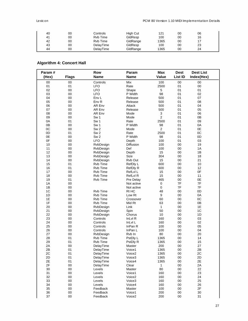
Algorithm 4: Concert Hall
Param # Row Param Max Dest Dest List(Hex) Flags Name Name Value List ID Index(Hex)
00 00 Controls Mix 100 00 0001 01 LFO Rate 2500 01 0002 00 LFO Shape 5 01 0103 00 LFO P Width 98 01 0204 00 Env L Release 500 01 0705 00 Env R Release 500 01 0806 00 AR Env Attack 500 01 0407 00 AR Env Release 500 01 0508 00 AR Env Mode 3 01 0609 00 Sw 1 Mode 2 01 0B0A 01 Sw 1 Rate 2500 01 090B 00 Sw 1 P Width 98 01 0A0C 00 Sw 2 Mode 2 01 0E0D 01 Sw 2 Rate 2500 01 0C0E 00 Sw 2 P Width 98 01 0D0F 00 LFO Depth 100 01 0310 00 RvbDesign Diffusion 100 00 1911 00 RvbDesign Def 100 00 1A12 00 RvbDesign Depth 15 00 1B13 00 RvbDesign Size 304 00 1814 00 RvbDesign Rvb Out 15 00 2115 01 Rvb Time RefDly L 600 00 1016 01 Rvb Time RefDly R 600 00 1217 00 Rvb Time RefLvl L 15 00 0F18 00 Rvb Time RefLvl R 15 00 1119 01 Rvb Time Pre Delay 465 00 0E1A 00 Not active 0 7F 7F1B 00 Not active 0 7F 7F1C 00 Rvb Time Rt HC 48 00 0D1D 00 Rvb Time Low Rt 9 00 0A1E 00 Rvb Time Crossover 60 00 0C1F 00 Rvb Time Mid Rt 63 00 0B20 00 RvbDesign Link 1 00 1E21 00 RvbDesign Spin 50 00 1C22 00 RvbDesign Chorus 10 00 1D23 00 Controls InLvl R 160 00 0324 00 Controls InLvl L 160 00 0225 00 Controls InPan R 100 00 0526 00 Controls InPan L 100 00 0427 00 RvbDesign Rvb In 80 00 2028 01 Rvb Time PstDly L 1365 00 1429 01 Rvb Time PstDly R 1365 00 152A 00 DelayTime Master 200 00 272B 01 DelayTime Voice1 1365 00 2B2C 01 DelayTime Voice2 1365 00 2C2D 01 DelayTime Voice3 1365 00 2D2E 01 DelayTime Voice4 1365 00 2E2F 00 DelayTime Clear 1 00 2A30 00 Levels Master 80 00 2231 00 Levels Voice1 160 00 2332 00 Levels Voice2 160 00 2433 00 Levels Voice3 160 00 2534 00 Levels Voice4 160 00 2635 00 Feedback Master 100 00 2F36 00 Feedback Voice1 200 00 3037 00 Feedback Voice2 200 00 31

28
LexiconPCM 80 Version 1.10 MIDI Implementation Details
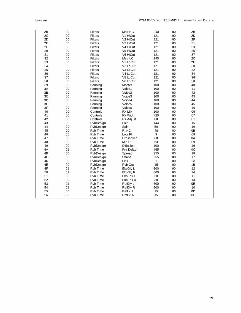
38 00 Feedback Voice3 200 00 3239 00 Feedback Voice4 200 00 333A 00 Panning Master 100 00 343B 00 Panning Voice1 100 00 353C 00 Panning Voice2 100 00 363D 00 Panning Voice3 100 00 373E 00 Panning Voice4 100 00 383F 00 Controls FX Mix 100 00 0840 00 Controls FX Adjust 80 00 0141 00 Rvb Time PstMix 100 00 1342 00 RvbDesign Rvb Width 720 00 1F43 00 Controls FX Width 720 00 0944 00 Controls Voice Dif 100 00 0745 00 Controls High Cut 121 00 0646 00 Rvb Time GldResp 100 00 1647 00 Rvb Time GldRange 1365 00 1748 00 DelayTime GldResp 100 00 2849 00 DelayTime GldRange 1365 00 29
Algorithm 5: M-Band+Rvb
Param # Row Param Max Dest Dest List(Hex) Flags Name Name Value List ID Index(Hex)
00 00 Controls Mix 100 00 0001 01 LFO Rate 2500 01 0002 00 LFO Shape 5 01 0103 00 LFO P Width 98 01 0204 00 Env L Release 500 01 0705 00 Env R Release 500 01 0806 00 AR Env Attack 500 01 0407 00 AR Env Release 500 01 0508 00 AR Env Mode 3 01 0609 00 Sw 1 Mode 2 01 0B0A 01 Sw 1 Rate 2500 01 090B 00 Sw 1 P Width 98 01 0A0C 00 Sw 2 Mode 2 01 0E0D 01 Sw 2 Rate 2500 01 0C0E 00 Sw 2 P Width 98 01 0D0F 00 LFO Depth 100 01 0310 00 Controls InLvl R 160 00 0311 00 Controls InLvl L 160 00 0212 00 Controls InPan R 100 00 0513 00 Controls InPan L 100 00 0414 00 Not active 0 7F 7F15 00 DelayTime Master 200 00 2316 01 DelayTime Voice1 43690 00 2517 01 DelayTime Voice2 43690 00 2618 01 DelayTime Voice3 43690 00 2719 01 DelayTime Voice4 43690 00 281A 01 DelayTime Voice5 43690 00 291B 01 DelayTime Voice6 43690 00 2A1C 00 DelayTime Clear 1 00 241D 00 Levels Master 80 00 1C1E 00 Levels Voice1 160 00 1D1F 00 Levels Voice2 160 00 1E20 00 Levels Voice3 160 00 1F21 00 Levels Voice4 160 00 2022 00 Levels Voice5 160 00 2123 00 Levels Voice6 160 00 2224 00 Feedback Master 100 00 3925 00 Feedback Voice1 200 00 3A26 00 Feedback Voice2 200 00 3B27 00 Feedback Voice3 200 00 3C28 00 Feedback Voice4 200 00 3D29 00 Feedback Voice5 200 00 3E2A 00 Feedback Voice6 200 00 3F
29
Lexicon PCM 80 Version 1.10 MIDI Implementation Details
2B 00 Filters Mstr HC 240 00 2B2C 00 Filters V1 HiCut 121 00 2D2D 00 Filters V2 HiCut 121 00 2F2E 00 Filters V3 HiCut 121 00 312F 00 Filters V4 HiCut 121 00 3330 00 Filters V5 HiCut 121 00 3531 00 Filters V6 HiCut 121 00 3732 00 Filters Mstr LC 240 00 2C33 00 Filters V1 LoCut 121 00 2E34 00 Filters V2 LoCut 121 00 3035 00 Filters V3 LoCut 121 00 3236 00 Filters V4 LoCut 121 00 3437 00 Filters V5 LoCut 121 00 3638 00 Filters V6 LoCut 121 00 3839 00 Panning Master 100 00 403A 00 Panning Voice1 100 00 413B 00 Panning Voice2 100 00 423C 00 Panning Voice3 100 00 433D 00 Panning Voice4 100 00 443E 00 Panning Voice5 100 00 453F 00 Panning Voice6 100 00 4640 00 Controls FX Mix 100 00 0641 00 Controls FX Width 720 00 0742 00 Controls FX Adjust 80 00 0143 00 RvbDesign Size 144 00 1544 00 RvbDesign Spin 50 00 1945 00 Rvb Time Rt HC 48 00 0B46 00 Rvb Time Low Rt 9 00 0847 00 Rvb Time Crossover 60 00 0A48 00 Rvb Time Mid Rt 63 00 0949 00 RvbDesign Diffusion 100 00 164A 01 Rvb Time Pre Delay 465 00 0C4B 00 RvbDesign Spread 255 00 184C 00 RvbDesign Shape 255 00 174D 00 RvbDesign Link 1 00 1A4E 00 RvbDesign Rvb Out 15 00 1B4F 01 Rvb Time EkoDly L 600 00 1250 01 Rvb Time EkoDly R 600 00 1451 00 Rvb Time EkoFbk L 30 00 1152 00 Rvb Time EkoFbk R 30 00 1353 01 Rvb Time RefDly L 600 00 0E54 01 Rvb Time RefDly R 600 00 1055 00 Rvb Time RefLvl L 15 00 0D56 00 Rvb Time RefLvl R 15 00 0F

30
LexiconPCM 80 Version 1.10 MIDI Implementation Details
Algorithm 6: Glide>Hall
Param # Row Param Max Dest Dest List(Hex) Flags Name Name Value List ID Index(Hex)
00 00 Controls Mix 100 00 0001 01 LFO Rate 2500 01 0002 00 LFO Shape 5 01 0103 00 LFO P Width 98 01 0204 00 Env L Release 500 01 0705 00 Env R Release 500 01 0806 00 AR Env Attack 500 01 0407 00 AR Env Release 500 01 0508 00 AR Env Mode 3 01 0609 00 Sw 1 Mode 2 01 0B0A 01 Sw 1 Rate 2500 01 090B 00 Sw 1 P Width 98 01 0A0C 00 Sw 2 Mode 2 01 0E0D 01 Sw 2 Rate 2500 01 0C0E 00 Sw 2 P Width 98 01 0D0F 00 LFO Depth 100 01 0310 00 Controls InLvl R 160 00 0311 00 Controls InLvl L 160 00 0212 00 Controls InPan R 100 00 0513 00 Controls InPan L 100 00 0414 00 Glide FX A Lvl L 160 00 1C15 00 Glide FX B Lvl L 160 00 2016 00 Glide FX A Lvl R 160 00 1E17 00 Glide FX B Lvl R 160 00 2218 00 Glide FX Fbk 08 0C 00 00 200 2419 00 Glide FX X-Fbk L 200 00 261A 00 Glide FX Fbk 08 0C 00 00 200 251B 00 Glide FX X-Fbk R 200 00 271C 00 Glide FX A Dly L 420 00 1D1D 00 Glide FX B Dly L 420 00 211E 00 Glide FX A Dly R 420 00 1F1F 00 Glide FX B Dly R 420 00 2320 00 Glide FX Gld Lvl 80 00 1B21 00 DelayTime Master 200 00 2F22 01 DelayTime Voice1 27511 00 3123 01 DelayTime Voice2 27511 00 3224 01 DelayTime Voice3 27511 00 3325 01 DelayTime Voice4 27511 00 3426 01 DelayTime Voice5 27511 00 3527 01 DelayTime Voice6 27511 00 3628 00 DelayTime Clear 1 00 3029 00 Levels Master 80 00 282A 00 Levels Voice1 160 00 292B 00 Levels Voice2 160 00 2A2C 00 Levels Voice3 160 00 2B2D 00 Levels Voice4 160 00 2C2E 00 Levels Voice5 160 00 2D2F 00 Levels Voice6 160 00 2E30 00 Feedback Mstr Fbk 100 00 3731 00 Feedback V1 08 0C 00 00 200 3932 00 Feedback V2 08 0C 00 00 200 3B33 00 Feedback V3 08 0C 00 00 200 3D34 00 Feedback V4 08 0C 00 00 200 3F35 00 Feedback V5 08 0C 00 00 200 4136 00 Feedback V6 08 0C 00 00 200 4337 00 Feedback Mstr XFbk 100 00 3838 00 Feedback V1 X-Fbk 200 00 3A39 00 Feedback V2 X-Fbk 200 00 3C3A 00 Feedback V3 X-Fbk 200 00 3E3B 00 Feedback V4 X-Fbk 200 00 403C 00 Feedback V5 X-Fbk 200 00 423D 00 Feedback V6 X-Fbk 200 00 443E 00 Controls Voice Dif 100 00 063F 00 Panning Master 100 00 45

31
Lexicon PCM 80 Version 1.10 MIDI Implementation Details
40 00 Panning Voice1 100 00 4641 00 Panning Voice2 100 00 4742 00 Panning Voice3 100 00 4843 00 Panning Voice4 100 00 4944 00 Panning Voice5 100 00 4A45 00 Panning Voice6 100 00 4B46 00 RvbDesign Rvb In 80 00 1947 00 Controls FX Mix 100 00 0748 00 Controls FX Width 720 00 0849 00 Controls FX Adjust 80 00 014A 00 RvbDesign Diffusion 100 00 134B 00 RvbDesign Def 100 00 144C 00 RvbDesign Depth 15 00 154D 00 RvbDesign Size 304 00 124E 00 RvbDesign Rvb Out 15 00 1A4F 01 Rvb Time RefDly L 600 00 0F50 01 Rvb Time RefDly R 600 00 1151 00 Rvb Time RefLvl L 15 00 0E52 00 Rvb Time RefLvl R 15 00 1053 01 Rvb Time Pre Delay 465 00 0D54 00 Not active 0 7F 7F55 00 Not active 0 7F 7F56 00 Rvb Time Rt HC 48 00 0C57 00 Rvb Time Low Rt 9 00 0958 00 Rvb Time Crossover 60 00 0B59 00 Rvb Time Mid Rt 63 00 0A5A 00 RvbDesign Link 1 00 185B 00 RvbDesign Spin 50 00 165C 00 RvbDesign Chorus 10 00 17
Algorithm 7: Chorus+Rvb
Param # Row Param Max Dest Dest List(Hex) Flags Name Name Value List ID Index(Hex)
00 00 Controls Mix 100 00 0001 01 LFO Rate 2500 01 0002 00 LFO Shape 5 01 0103 00 LFO P Width 98 01 0204 00 Env L Release 500 01 0705 00 Env R Release 500 01 0806 00 AR Env Attack 500 01 0407 00 AR Env Release 500 01 0508 00 AR Env Mode 3 01 0609 00 Sw 1 Mode 2 01 0B0A 01 Sw 1 Rate 2500 01 090B 00 Sw 1 P Width 98 01 0A0C 00 Sw 2 Mode 2 01 0E0D 01 Sw 2 Rate 2500 01 0C0E 00 Sw 2 P Width 98 01 0D0F 00 LFO Depth 100 01 0310 00 Controls InLvl R 160 00 0311 00 Controls InLvl L 160 00 0212 00 Controls InPan R 100 00 0513 00 Controls InPan L 100 00 0414 00 Not active 0 7F 7F15 00 Controls High Cut 121 00 0616 00 Controls FX Width 720 00 0817 00 DelayTime Master 200 00 2318 01 DelayTime Voice1 1365 00 2719 01 DelayTime Voice2 1365 00 281A 01 DelayTime Voice3 1365 00 291B 01 DelayTime Voice4 1365 00 2A1C 01 DelayTime Voice5 1365 00 2B1D 01 DelayTime Voice6 1365 00 2C1E 00 DelayTime Clear 1 00 261F 00 DelayTime GldResp 100 00 24

32
LexiconPCM 80 Version 1.10 MIDI Implementation Details
20 00 DelayTime GldRange 1365 00 2521 00 Chorus MstDepth 200 00 2D22 00 Chorus V1 Depth 500 00 2F23 00 Chorus V2 Depth 500 00 3124 00 Chorus V3 Depth 500 00 3325 00 Chorus V4 Depth 500 00 3526 00 Chorus V5 Depth 500 00 3727 00 Chorus V6 Depth 500 00 3928 00 Chorus MstRate 200 00 2E29 00 Chorus V1 Rate 100 00 302A 00 Chorus V2 Rate 100 00 322B 00 Chorus V3 Rate 100 00 342C 00 Chorus V4 Rate 100 00 362D 00 Chorus V5 Rate 100 00 382E 00 Chorus V6 Rate 100 00 3A2F 00 Levels Master 80 00 1C30 00 Levels Voice1 160 00 1D31 00 Levels Voice2 160 00 1E32 00 Levels Voice3 160 00 1F33 00 Levels Voice4 160 00 2034 00 Levels Voice5 160 00 2135 00 Levels Voice6 160 00 2236 00 Feedback Master 100 00 3B37 00 Feedback Voice1 200 00 3C38 00 Feedback Voice2 200 00 3D39 00 Feedback Voice3 200 00 3E3A 00 Feedback Voice4 200 00 3F3B 00 Feedback Voice5 200 00 403C 00 Feedback Voice6 200 00 413D 00 Panning Master 100 00 423E 00 Panning Voice1 100 00 433F 00 Panning Voice2 100 00 4440 00 Panning Voice3 100 00 4541 00 Panning Voice4 100 00 4642 00 Panning Voice5 100 00 4743 00 Panning Voice6 100 00 4844 00 Controls FX Mix 100 00 0745 00 Controls FX Adjust 80 00 0146 00 RvbDesign Size 144 00 1647 00 RvbDesign Spin 50 00 1948 00 Rvb Time Rt HC 48 00 0C49 00 Rvb Time Low Rt 9 00 094A 00 Rvb Time Crossover 60 00 0B4B 00 Rvb Time Mid Rt 63 00 0A4C 00 RvbDesign Diffusion 100 00 174D 01 Rvb Time Pre Delay 465 00 0D4E 00 Not active 0 7F 7F4F 00 RvbDesign Attack 100 00 1850 00 RvbDesign Link 1 00 1A51 00 RvbDesign Rvb Out 15 00 1B52 01 Rvb Time EkoDly L 600 00 1353 01 Rvb Time EkoDly R 600 00 1554 00 Rvb Time EkoFbk L 30 00 1255 00 Rvb Time EkoFbk R 30 00 1456 01 Rvb Time RefDly L 600 00 0F57 01 Rvb Time RefDly R 600 00 1158 00 Rvb Time RefLvl L 15 00 0E59 00 Rvb Time RefLvl R 15 00 10

33
Lexicon PCM 80 Version 1.10 MIDI Implementation Details
Algorithm 8: Res1>Plate
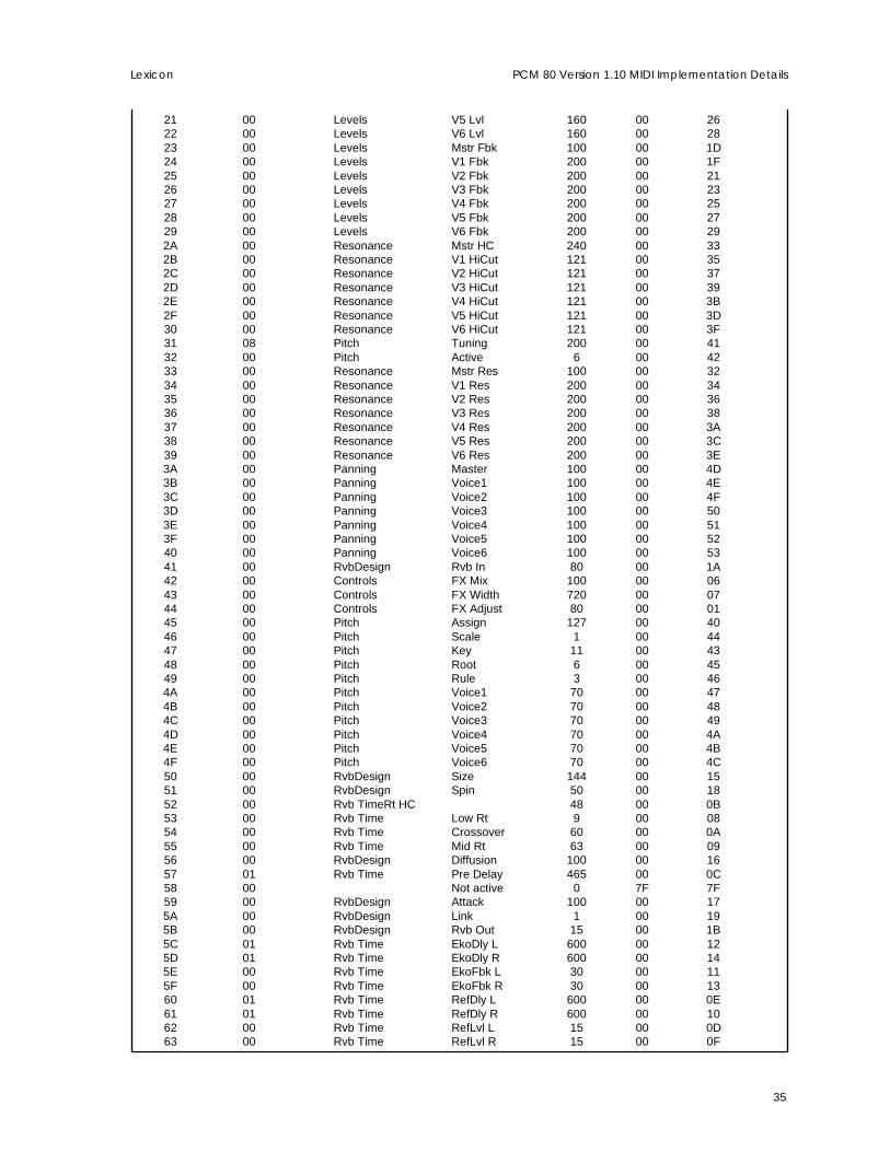
Param # Row Param Max Dest Dest List(Hex) Flags Name Name Value List ID Index(Hex)
00 00 Controls Mix 100 00 0001 01 LFO Rate 2500 01 0002 00 LFO Shape 5 01 0103 00 LFO P Width 98 01 0204 00 Env L Release 500 01 0705 00 Env R Release 500 01 0806 00 AR Env Attack 500 01 0407 00 AR Env Release 500 01 0508 00 AR Env Mode 3 01 0609 00 Sw 1 Mode 2 01 0B0A 01 Sw 1 Rate 2500 01 090B 00 Sw 1 P Width 98 01 0A0C 00 Sw 2 Mode 2 01 0E0D 01 Sw 2 Rate 2500 01 0C0E 00 Sw 2 P Width 98 01 0D0F 00 LFO Depth 100 01 0310 00 Controls InLvl R 160 00 0311 00 Controls InLvl L 160 00 0212 00 Controls InPan R 100 00 0513 00 Controls InPan L 100 00 0414 00 DelayTime Master 200 00 2A15 01 DelayTime Voice1 38229 00 2C16 01 DelayTime Voice2 38229 00 2D17 01 DelayTime Voice3 38229 00 2E18 01 DelayTime Voice4 38229 00 2F19 01 DelayTime Voice5 38229 00 301A 01 DelayTime Voice6 38229 00 311B 00 DelayTime Clear 1 00 2B1C 00 Levels Mstr Lvl 80 00 1C1D 00 Levels V1 Lvl 160 00 1E1E 00 Levels V2 Lvl 160 00 201F 00 Levels V3 Lvl 160 00 2220 00 Levels V4 Lvl 160 00 2421 00 Levels V5 Lvl 160 00 2622 00 Levels V6 Lvl 160 00 2823 00 Levels Mstr Fbk 100 00 1D24 00 Levels V1 Fbk 200 00 1F25 00 Levels V2 Fbk 200 00 2126 00 Levels V3 Fbk 200 00 2327 00 Levels V4 Fbk 200 00 2528 00 Levels V5 Fbk 200 00 2729 00 Levels V6 Fbk 200 00 292A 00 Resonance Mstr HC 240 00 332B 00 Resonance V1 HiCut 121 00 352C 00 Resonance V2 HiCut 121 00 372D 00 Resonance V3 HiCut 121 00 392E 00 Resonance V4 HiCut 121 00 3B2F 00 Resonance V5 HiCut 121 00 3D30 00 Resonance V6 HiCut 121 00 3F31 08 Pitch Tuning 200 00 4132 00 Pitch Active 6 00 4233 00 Resonance Mstr Res 100 00 3234 00 Resonance V1 Res 200 00 3435 00 Resonance V2 Res 200 00 3636 00 Resonance V3 Res 200 00 3837 00 Resonance V4 Res 200 00 3A38 00 Resonance V5 Res 200 00 3C39 00 Resonance V6 Res 200 00 3E3A 00 Panning Master 100 00 443B 00 Panning Voice1 100 00 453C 00 Panning Voice2 100 00 463D 00 Panning Voice3 100 00 473E 00 Panning Voice4 100 00 48

34
LexiconPCM 80 Version 1.10 MIDI Implementation Details
3F 00 Panning Voice5 100 00 4940 00 Panning Voice6 100 00 4A41 00 RvbDesign Rvb In 80 00 1A42 00 Controls FX Mix 100 00 0643 00 Controls FX Width 720 00 0744 00 Controls FX Adjust 80 00 0145 00 Pitch Assign 127 00 4046 00 Pitch Unison 1 00 4347 00 RvbDesign Size 144 00 1548 00 RvbDesign Spin 50 00 1849 00 Rvb Time Rt HC 48 00 0B4A 00 Rvb Time Low Rt 9 00 084B 00 Rvb Time Crossover 60 00 0A4C 00 Rvb Time Mid Rt 63 00 094D 00 RvbDesign Diffusion 100 00 164E 01 Rvb Time Pre Delay 465 00 0C4F 00 Not active 0 7F 7F50 00 RvbDesign Attack 100 00 1751 00 RvbDesign Link 1 00 1952 00 RvbDesign Rvb Out 15 00 1B53 01 Rvb Time EkoDly L 600 00 1254 01 Rvb Time EkoDly R 600 00 1455 00 Rvb Time EkoFbk L 30 00 1156 00 Rvb Time EkoFbk R 30 00 1357 01 Rvb Time RefDly L 600 00 0E58 01 Rvb Time RefDly R 600 00 1059 00 Rvb Time RefLvl L 15 00 0D5A 00 Rvb Time RefLvl R 15 00 0F
Algorithm 9: Res 2>Plate
Param # Row Param Max Dest Dest List(Hex) Flags Name Name Value List ID Index(Hex)
00 00 Controls Mix 100 00 0001 01 LFO Rate 2500 01 0002 00 LFO Shape 5 01 0103 00 LFO P Width 98 01 0204 00 Env L Release 500 01 0705 00 Env R Release 500 01 0806 00 AR Env Attack 500 01 0407 00 AR Env Release 500 01 0508 00 AR Env Mode 3 01 0609 00 Sw 1 Mode 2 01 0B0A 01 Sw 1 Rate 2500 01 090B 00 Sw 1 P Width 98 01 0A0C 00 Sw 2 Mode 2 01 0E0D 01 Sw 2 Rate 2500 01 0C0E 00 Sw 2 P Width 98 01 0D0F 00 LFO Depth 100 01 0310 00 Controls InLvl R 160 00 0311 00 Controls InLvl L 160 00 0212 00 Controls InPan R 100 00 0513 00 Controls InPan L 100 00 0414 00 DelayTime Master 200 00 2A15 01 DelayTime Voice1 38229 00 2C16 01 DelayTime Voice2 38229 00 2D17 01 DelayTime Voice3 38229 00 2E18 01 DelayTime Voice4 38229 00 2F19 01 DelayTime Voice5 38229 00 301A 01 DelayTime Voice6 38229 00 311B 00 DelayTime Clear 1 00 2B1C 00 Levels Mstr Lvl 80 00 1C1D 00 Levels V1 Lvl 160 00 1E1E 00 Levels V2 Lvl 160 00 201F 00 Levels V3 Lvl 160 00 2220 00 Levels V4 Lvl 160 00 24
35
Lexicon PCM 80 Version 1.10 MIDI Implementation Details
21 00 Levels V5 Lvl 160 00 2622 00 Levels V6 Lvl 160 00 2823 00 Levels Mstr Fbk 100 00 1D24 00 Levels V1 Fbk 200 00 1F25 00 Levels V2 Fbk 200 00 2126 00 Levels V3 Fbk 200 00 2327 00 Levels V4 Fbk 200 00 2528 00 Levels V5 Fbk 200 00 2729 00 Levels V6 Fbk 200 00 292A 00 Resonance Mstr HC 240 00 332B 00 Resonance V1 HiCut 121 00 352C 00 Resonance V2 HiCut 121 00 372D 00 Resonance V3 HiCut 121 00 392E 00 Resonance V4 HiCut 121 00 3B2F 00 Resonance V5 HiCut 121 00 3D30 00 Resonance V6 HiCut 121 00 3F31 08 Pitch Tuning 200 00 4132 00 Pitch Active 6 00 4233 00 Resonance Mstr Res 100 00 3234 00 Resonance V1 Res 200 00 3435 00 Resonance V2 Res 200 00 3636 00 Resonance V3 Res 200 00 3837 00 Resonance V4 Res 200 00 3A38 00 Resonance V5 Res 200 00 3C39 00 Resonance V6 Res 200 00 3E3A 00 Panning Master 100 00 4D3B 00 Panning Voice1 100 00 4E3C 00 Panning Voice2 100 00 4F3D 00 Panning Voice3 100 00 503E 00 Panning Voice4 100 00 513F 00 Panning Voice5 100 00 5240 00 Panning Voice6 100 00 5341 00 RvbDesign Rvb In 80 00 1A42 00 Controls FX Mix 100 00 0643 00 Controls FX Width 720 00 0744 00 Controls FX Adjust 80 00 0145 00 Pitch Assign 127 00 4046 00 Pitch Scale 1 00 4447 00 Pitch Key 11 00 4348 00 Pitch Root 6 00 4549 00 Pitch Rule 3 00 464A 00 Pitch Voice1 70 00 474B 00 Pitch Voice2 70 00 484C 00 Pitch Voice3 70 00 494D 00 Pitch Voice4 70 00 4A4E 00 Pitch Voice5 70 00 4B4F 00 Pitch Voice6 70 00 4C50 00 RvbDesign Size 144 00 1551 00 RvbDesign Spin 50 00 1852 00 Rvb Time Rt HC 48 00 0B53 00 Rvb Time Low Rt 9 00 0854 00 Rvb Time Crossover 60 00 0A55 00 Rvb Time Mid Rt 63 00 0956 00 RvbDesign Diffusion 100 00 1657 01 Rvb Time Pre Delay 465 00 0C58 00 Not active 0 7F 7F59 00 RvbDesign Attack 100 00 175A 00 RvbDesign Link 1 00 195B 00 RvbDesign Rvb Out 15 00 1B5C 01 Rvb Time EkoDly L 600 00 125D 01 Rvb Time EkoDly R 600 00 145E 00 Rvb Time EkoFbk L 30 00 115F 00 Rvb Time EkoFbk R 30 00 1360 01 Rvb Time RefDly L 600 00 0E61 01 Rvb Time RefDly R 600 00 1062 00 Rvb Time RefLvl L 15 00 0D63 00 Rvb Time RefLvl R 15 00 0F

36
LexiconPCM 80 Version 1.10 MIDI Implementation Details
Appendix A: Patch Sources by Index
Remapping of MIDI controllersIn the MIDI spec, two continuous controllers are reserved for Bank change. Those controllers are #0 and#32. Those controllers are not available as patch sources in the PCM 80, as their use could possibly causeunwanted effects. Therefore, controller IDs are remapped in the patch source list. Controllers 0 and 32are excluded. This means that you must subtract 1 from any MIDI Controller# below #33 and you mustsubtract 2 from Controller #33 on up. For example:
Controller # Patch Source Index0 Not available1-31 0-3032 Not available33-119 31-117
MIDI controls above 119 are reserved for other messages and are not available as controllers. They arealso excluded from the patch source table.
Patch Source TableAll patch sources have outputs in the range of 0-127. See the preceding table for exclusions
Source Index Controller
0-117 MIDI controllers 0-119118 Pitch bend119 Channel pressure120 Velocity of last-played note121 Last note number122 Lowest current note number123 Highest current note number124 Clock commands125 LFO (selectable output)126 LFO Sine127 LFO Cosine128 LFO Square129 LFO Sawtooth130 LFO Pulse131 LFO Triangle132 Left Envelope follower133 Right Envelope follower134 AR Envelope generator135 Latch136 Timeswitch 1137 Timeswitch 2138 Composite Timeswitch139 Mono input level140 Left input level141 Right input level142 Continuous foot pedal143 Footswitch 1144 Footswitch 2145 ADJUST knob146 Tempo147-253 Reserved — Do not use these values.254 Always on (127)255 Always off (0)

37
Lexicon PCM 80 Version 1.10 MIDI Implementation Details
Appendix B: MIDI Bank assignments
Effects in the PCM 80 are accessed by Bank and Program numbers. Banks are assigned as follows:Bank 0-3 Internal presets (Displayed as P0-P3)
Bank 4 User generated effects (Displayed as R)
Bank 5-9 Extension presets. Presets are loaded into these banks from algorithm cards.(Displayed as X0-X4)
Bank 10- Card banks, either user generated or preset, depending on card type. Displayed asC0, C1, etc. Bank numbers above 9 are displayed alphabetically, beginning withCA.
Program numbers range from 0-49. Numbers greater than 49 are ignored. The exception is mapped modein which a program number (0-127) is used to look up a bank/program combination from a table.

38
LexiconPCM 80 Version 1.10 MIDI Implementation Details
Appendix C: MIDI inquiry message
The MIDI specification defines a global message that allows a host device to determine what sorts ofdevices are connected. This message is interpreted by the PCM 80 as follows:
Inquiry message from host to PCM 80:
Byte # ByteValue Description Notes1 0xf0 SysEx ID
2 0x7e Universalnon-realtime header
3 0iii iiii Channel Treated as the SysEx Device ID assigned to the PCM 80
4 0x06 General information
5 0x01 Device inquiry
6 0xF7 EOX
Response from PCM 80:
Byte # ByteValue Description Notes1 0xf0 SysEx ID
2 0x7e Universalnon-realtime header
3 0iii iiii Channel. SysExdevice ID assignedto the PCM 80
4 0x06 General information
5 0x02 Device ID message
6 0x06 Lexicon SysEx ID
7 0x00 Family code LSB
8 0x00 Family code MSB
9 0x07 Family membercode LSB This is the PCM 80 SysEx product code (byte 3 of a standard SysEx
message.)
10 0x00 Family membercode MSB
11 0iii iiii Major softwarerevision # See System Configuration Response.
12 0iii iiii Minor softwarerevision # See System Configuration Response.
13 0iii iiii Release code For normal released code this byte is 0. Any other value indicatestest code that is not under general release
14 0x00 Unused revisiondata
15 0xf7 EOX

39
Lexicon PCM 80 Version 1.10 MIDI Implementation Details
Appendix D: List of Error Messages
These messages are displayed on the PCM 80 when MIDI or other errors occur.
MIDI reset complete Displayed after a MIDI reset has been received or transmitted.
Receiving SysExdata... Displayed whenever System Exclusive data is being received by the
PCM 80. Received data must match the ID specified in the PCM 80 MIDIrow or the ID must be 127 (broadcast).
Transmitting MIDIbulk data... Dump is progressing. May not appear for dumps of very small data sets.
Does not appear if verbose mode is off.
MIDI data dumpis complete Dump is over. Does not appear if verbose mode is off.
SysEx checksum error Checksum error in incoming data.
SysEx data overrun SysEx data has been transmitted to the PCM 80 faster than it can beprocessed.
SysEx data error... Indicates some sort of corruption in the SysEx data.
Cannot store dataas requested Usually indicates invalid Bank/offset specification. Bank may not be
writeable, or may not be present, or offset may be >49.
Operation failed Catchall error message. In some store operations, may indicate that acard is write-protected
Can’t dump registerNeed algorithm card Displayed when a bank or register which requires a card-based algo-
rithm is being dumped.
Effect unchangedNo data in dump The dump just received was originally transmitted without an algorithm
card and, therefore, does not contain all necessary data. The destina-tion of the dump is not overwritten.
Effect unchangedNeed algorithm card The incoming dump requires an algorithm card to be decoded. The
destination of the dump is not overwritten.
Bad patch datawas corrected A program load failed because of corrupt patch data, probably bad data
in a MIDI transfer of effect data. The effect should be carefully screenedand may not be usable.

40
LexiconPCM 80 Version 1.10 MIDI Implementation Details
Appendix E: System (Type 0) Parameters
These parameters are global (not part of a preset). The automation column indicates transmission viaSysEx automation.
Param# Max Auto-Dec Hex Description Value mation? Notes
0 00 Audio source 2 n 0=Digital; 1=Analog 48kHz; 2=Analog 44.1kHz
1 01 Analog Input Level 100 ? Percentage, from 0-100
2 02 Digital Input Level 100 ? Percentage, from 0-100
3 03 MIDI Receive 17 n 0=Off; 1-16=MIDI channels; 17=Omni
4 04 MIDI transmiton/off/channel 16 n 0=Off; 1-16=Channel for transmission of controller data
5 05 External tapsource patch
sourcelist y
6 06 External tapthreshold 127 y
7 07 MIDI controller IDfor continuouspedal 117 y
8 08 MIDI controller IDfor footswitch 1 117 y
9 09 MIDI controller IDfor Adjust knob 117 n
10 0A MIDI SysEx device ID 126 n This parameter is not controllable from MIDI, but is re-turned by a request for the parameter value.
11 0B MIDI SysEx enable 1 n This parameter is not controllable from MIDI, but is re-turned by a request for the parameter value.
12 0C Memory protect 1 n 0=Off; 1=On
13 0D Pro/Go Mode 1 y 0=Go; 1=Pro
14 0E Mix Pgm/Global 1 y 0=Program; 1=Global
15 0F Tempo Pgm/Global 1 y 0=Program; 1=Global
16 10 Autoload 1 y 0=Off; 1=On
17 11 Bypass Mode 3 y 0=All Mute; 1=Input Mute;
2=Output Mute; 3=Bypass
18 12 MIDI controller IDfor Footswitch 2 117 y
19 13 Patch update mode 1 y 0=Immediate; 1=Delayed
20 14 MIDI ProgramChange mode 3 n 0=On; 1=Off; 2=Mapped; 3=Chained
21 15 Map select 127 y Actual number of valid maps depends on presence andtype of card. The parameter specific message for thisparameter will always return the maximum possiblerange. The actual useful values should be determinedfrom the Configuration Response message.
22 16 Chain select 127 y Actual number of valid chains depends on presence andtype of card. The parameter specific message for thisparameter will always return the maximum possiblerange. The actual useful values should be determinedfrom the Configuration Response message.
23 17 Pgm+ source 120 y 0=No Assignment; 1-118=MIDI controllers; 119=Foot Sw1;120=Foot Sw 2.
24 18 Pgm- source 120 y 0=No Assignment; 1-118=MIDI controllers; 119=Foot Sw1;120=Foot Sw 2.
25 19 Program Changebypass mode 1 y 0=Mute; 1=Bypass

41
Lexicon PCM 80 Version 1.10 MIDI Implementation Details
26 1A Global Mix value 100 y 0=Dry; 100=Wet
27 1B Transmit MIDI clock 1 n 0=Do not transmit clock; 1=Transmit clock
28 1C Dump speed 2 n 0=Slow; 1=Medium; 2=Fast Note: This causes brieftimeouts to be inserted between individual effects In abank dump. There is no other effect from this parameter.This is helpful for slow or memory-bound devices whichmay have difficulty digesting the large amount of data in abank dump. Packets are sent as follows:
Header and label information; Pause; 1st effect; Pause;2nd-50th effects with pauses. Final effect data includesEOX
29 1D MIDI automationmode 1 n 0=Off; 1=On
30 1E Transmitted DeviceID for automation 127 n 0-126=specific target ID’s; 127=broadcast
31 1F Tempo blink 1 y 0=On; 1=Off
32 20 Global tempo value 360 y 40-400BPM in 1 beat increments.
33 21 Dig In status 0 n No effect when transmitted.
34 22 Selects display ofdigital error 5 n 0=Validity; 1=Confidence; 2=Slip Sample; 3=CRC;
4=Parity
35 23 Autolock enable 1 y 0=disabled; 1=enabled
36 24 Transmitted SCMSselection 2 n 0=No Copy; 1=Single Copy; 2=Multi Copy
37 25 Transmitted emphasisselection 2 n 0=No Emphasis; 1=Emphasis; 2=Pass Thru
38 26 Tempo source 1 y 0=Internal; 1=MIDI
39 27 Analog output level 1 n 0=-10dBu; 1=+4 dBu
40 28 Sample dump outputresolution 20 y Number of valid bits for sample dump. This parameter will
only be meaningful for algorithms that support MIDIsample dump.
41 29 Bypass controllerassign 120 y 0=No Assignment; 1-118=MIDI controllers; 119=Foot Sw
1; 120=Foot Sw2.

42
LexiconPCM 80 Version 1.10 MIDI Implementation Details
Appendix F: Patchable (Type 1) Parameters
These are the patchable parameters that are the same (both offset and range) for all algorithms. DSP-specific parameters are not listed.
Param# MaxDec Hex Description Value Notes
0 00 Mix 100 Only when Pgm is selected as Mix mode.
1 01 LFO rate 1000 0-10Hz in .01Hz increments
2 02 LFO shape 6 0=Sine; 1=Cosine; 2=Square; 3=Sawtooth; 4=Pulse;5=Triangle; 6=Random
3 03 LFO pulsewidth 98 1-99 %
4 04 Follow ENV L 500 0-10 sec in 20ms increments
5 05 Follow ENV R 500 0-10 sec in 20ms increments
6 06 AR envelope attack 500 0-10 sec in 20ms increments
7 07 AR envelope release 500 0-10 sec in 20ms increments
8 08 AR envelopegenerator mode 3 0=Off; 1=One Shot; 2=Retrigger; 3=Repeat
9 09 Timeswitch 1 mode 2 0=Off; 1=Switch; 2=Ramp
10 0A Timeswitch 1 rate 1000 0-10Hz in .01Hz increments
11 0B Timeswitch 1pulsewidth 98 1-99 %
12 0C Timeswitch 2 mode 2 0=Off; 1=Switch; 2=Ramp
13 0D Timeswitch 2 rate 1000 0-10Hz in .01Hz increments
14 0E Timeswitch 2pulsewidth 98 1-99 %
15 0F LFO depth 100 0-100%
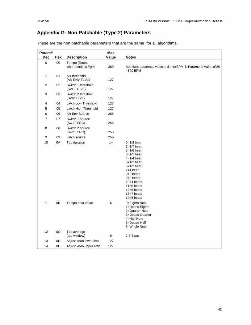
43
Lexicon PCM 80 Version 1.10 MIDI Implementation Details
Appendix G: Non-Patchable (Type 2) Parameters
These are the non patchable parameters that are the same for all algorithms.
Param# MaxDec Hex Description Value Notes
0 00 Tempo (Rate),when mode is Pgm 360 Add 40 to parameter value to derive BPM, ie Parameter Value of 80
=120 BPM
1 01 AR threshold(AR ENV TLVL) 127
2 02 Switch 1 threshold(SW 1 TLVL) 127
3 03 Switch 2 threshold(SW2 TLVL) 127
4 04 Latch Low Threshold 127
5 05 Latch High Threshold 127
6 06 AR Env Source 255
7 07 Switch 1 source(Sw1 TSRC) 255
8 08 Switch 2 source(Sw2 TSRC) 255
9 09 Latch source 255
10 0A Tap duration 14 0=1/8 beat1=1/7 beat2=1/6 beat3=1/5 beat4=1/4 beat5=1/3 beat6=1/2 beat7=1 beat8=2 beats9=3 beats10=4 beats11=5 beats12=6 beats13=7 beats14=8 beats
11 0B Tempo beat value 6 0=Eighth Note1=Dotted Eighth2=Quarter Note3=Dotted Quarter4=Half Note5=Dotted Half6=Whole Note
12 0C Tap average(tap window) 6 2-8 Taps
13 0D Adjust knob lower limit 127
14 0E Adjust knob upper limit 127

44
LexiconPCM 80 Version 1.10 MIDI Implementation Details
MIDI Implementation Chart
Lexicon PCM 80Digital Effects System
Mode 1: OMNI ON, POLY Mode 2: OMNI ON, MONO O : Yes OX: SelectableMode 3: OMNI OFF, POLY Mode 4: OMNI OFF, MONO X : No
Function Transmitted Recognized Remarks
Basic Default 1 1Channel Changed 1-16 1-16
Mode Default X Mode 1, 3Messages X XAltered X
Note X 0-127 Last Note, Low Note,Number High Note used as
controllers
Velocity Note ON X O 9n v = 1-127 used as controllerNote OFF
After Keys X XTouch Channel X O
Pitch Bend X O
Control 1-119 OX OX ADJUST, Footpedal,Change Footswitch 1, and
Footswitch 2 can be assigned controllers 1-119 for MIDItransmit
Program X 0-127 See ImplementationChange True # Details
System Lexicon OX OX product ID=6Exclusive Real-time X X
non Real-time X OX device ID
System :Song Pos X XCommon :Song Sel X X
:Tune X X
System :Clock OX OXReal Time :Commands X OX* START, STOP and
CONTINUE arepatchable as a switch:START/CONTINUE=127;STOP=0
Aux :Local ON/OFF X XMessages :All Notes OFF X O
:Active Sense X X:Reset All Controllers OX OX
Notes

45
Lexicon PCM 80 Version 1.10 MIDI Implementation Details

Lexicon, Inc.3 Oak ParkBedford, MA 01730 USATel 781-280-0300Fax 781-280-0490www.lexicon.com
Lexicon Part No. 070-11486 Printed in U.S.A.