PCI MNL 124-18 Specification for Fire Resistance of ... · PDF file14 PCI manual, rational...
43
1| Page PCI MNL 124-18 1 2 Specification for Fire Resistance of 3 Precast/Prestressed Concrete 4 5 A PCI Standard 6 FOREWORD 7 The Precast/Prestressed Concrete Institute first promulgated a manual for the design for fire resistance of precast 8 prestressed concrete in 1977. A second edition was prepared in 1989 and a third edition in 2011. Recommended 9 design procedures in these three editions were based on fire test data and reports for precast prestressed concrete 10 dating back to the 1960’s. Little has changed in fundamental design for fire resistance. While fire resistance is 11 discussed in other publications as “calculated” fire resistance, these provisions have generally been prescriptive. 12 That is, tables of information are used to select concrete mass or protection for steel. Since the first edition of the 13 PCI manual, rational design, which is truly a fire resistance calculation procedure, has been illustrated. Though not a 14 standard, the first edition of the International Building Code in 2000 referenced the procedures in the PCI fire design 15 manual as being acceptable for prestressed slabs not covered elsewhere. 16 With 2014 designation of PCI as an ANSI Accredited Standards Developer by the American National Standards 17 Institute, the material for fire resistance of precast and precast, prestressed concrete was deemed important enough 18 to the precast industry that the newest edition of the provisions would be developed in a consensus standard form. 19 Thus, the design procedures would be referenced in the 2021 International Building Code as a standard developed 20 through a ANSI consensus process. 21 22 PREFACE 23 This standard was developed following the protocols required by the PCI Group Operations Manual. The provisions 24 were first generated and balloted in the PCI Fire Committee. A review and comment by the PCI Technical Activities 25 Council (TAC) followed and resulted in substantive changes to the document. These changes were balloted by the 26 PCI Fire Committee and finally accepted by the PCI TAC. The document was then submitted to the PCI Standards 27 Committee where additional review and balloting took place. The membership of that committee is balanced 28 according to the rules of ANSI accreditation. In addition, a public review period was provided and public comments 29 were resolved through the PCI Standards Committee. The entire process is a consensus process involving PCI 30 members, non-members of PCI and the general public. 31 32 Note to reviewers: Graphs and figures that have been scanned and copied into this document will be 33 updated for metric units when final layout is done. 34 35
-
Upload
nguyenmien -
Category
Documents
-
view
234 -
download
8
Transcript of PCI MNL 124-18 Specification for Fire Resistance of ... · PDF file14 PCI manual, rational...

1|P a g e
PCI MNL 124-18 1 2
Specification for Fire Resistance of 3
Precast/Prestressed Concrete 4 5
A PCI Standard 6
FOREWORD 7The Precast/Prestressed Concrete Institute first promulgated a manual for the design for fire resistance of precast 8prestressed concrete in 1977. A second edition was prepared in 1989 and a third edition in 2011. Recommended 9design procedures in these three editions were based on fire test data and reports for precast prestressed concrete 10dating back to the 1960’s. Little has changed in fundamental design for fire resistance. While fire resistance is 11discussed in other publications as “calculated” fire resistance, these provisions have generally been prescriptive. 12That is, tables of information are used to select concrete mass or protection for steel. Since the first edition of the 13PCI manual, rational design, which is truly a fire resistance calculation procedure, has been illustrated. Though not a 14standard, the first edition of the International Building Code in 2000 referenced the procedures in the PCI fire design 15manual as being acceptable for prestressed slabs not covered elsewhere. 16With 2014 designation of PCI as an ANSI Accredited Standards Developer by the American National Standards 17Institute, the material for fire resistance of precast and precast, prestressed concrete was deemed important enough 18to the precast industry that the newest edition of the provisions would be developed in a consensus standard form. 19Thus, the design procedures would be referenced in the 2021 International Building Code as a standard developed 20through a ANSI consensus process. 21 22
PREFACE 23This standard was developed following the protocols required by the PCI Group Operations Manual. The provisions 24were first generated and balloted in the PCI Fire Committee. A review and comment by the PCI Technical Activities 25Council (TAC) followed and resulted in substantive changes to the document. These changes were balloted by the 26PCI Fire Committee and finally accepted by the PCI TAC. The document was then submitted to the PCI Standards 27Committee where additional review and balloting took place. The membership of that committee is balanced 28according to the rules of ANSI accreditation. In addition, a public review period was provided and public comments 29were resolved through the PCI Standards Committee. The entire process is a consensus process involving PCI 30members, non-members of PCI and the general public. 31
32Note to reviewers: Graphs and figures that have been scanned and copied into this document will be 33updated for metric units when final layout is done. 34 35
RBecker
Highlight
RBecker
Highlight
RBecker
Highlight
RBecker
Highlight

2|P a g e
36TABLE OF CONTENTS 37
38Chapter 1—General 39
1.1—Scope 401.2—Definitions 411.3—Notation 421.4—Referenced standards 43
Chapter 2—General requirements 442.1—General 452.2—Steel properties 462.3—Concrete properties 472.4—Determining restrained/unrestrained conditions 482.5—Methods for determining structural fire resistance of precast/prestressed concrete elements 49
Chapter 3—Precast concrete elements 503.1—General 513.2—Prescriptive requirements 523.3—Rational design for slabs and beams 53
Chapter 4—Special considerations 544.1—General 554.2—Protection of openings 564.3—Protection of connections 57
58Appendix A—Standard Commentary 59 60

3|P a g e
CHAPTER 1—GENERAL 61
621.1—Scope. This document specifies requirements for the design of precast and precast, prestressed concrete 63elements to resist fire and provide fire protection. For the purposes of this standard, “precast concrete element” shall 64mean a plant-cast concrete member reinforced with any combination of nonprestressed deformed reinforcement or 65prestressed strand. This standard provides acceptable methods to determine the fire resistance of precast concrete 66structural elements, including walls, floor and roof slabs, beams, and columns, and the fire protection for structural 67steel columns with precast concrete covers. The fire exposure and applicable end-point criteria of ASTM E119 shall 68be used in the application of these methods for design. Except where the requirements of this standard are more 69stringent, elements shall conform to the requirements of ACI 318. 70 71
1.2—Definitions. The following definitions shall apply for the purposes of this standard: 72
approved—approved by the building official responsible for enforcing the legally adopted building code of 73which this standard is a part, or approved by some other authority having jurisdiction. 74bar, high-strength alloy steel—steel bars conforming to the requirements of ASTM A722/A722M. 75beam—a structural member with a primary load demand in flexure or shear. 76blanket, ceramic fiber—mineral wool insulating material made of alumina-silica fibers and having a density of 774 to 8 lb/ft3 (64 to 128 kg/m3). 78board, mineral—a rigid, felted thermal insulation board complying with ASTM C726. 79building code—a legal document that establishes the minimum requirements necessary for building design and 80construction to provide for public health and safety. 81concrete, carbonate aggregate—concrete made with coarse aggregate consisting mainly of calcium or 82magnesium carbonate or a combination of calcium and magnesium carbonate (for example, limestone or 83dolomite). 84concrete, lightweight-aggregate—concrete made with aggregates conforming to ASTM C330/C330M. 85concrete, normalweight—concrete made with aggregates conforming to ASTM C33/C33M. 86concrete, perlite—nonstructural lightweight insulating concrete made by mixing perlite aggregate complying 87with ASTM C332 with portland cement slurry, having a density of approximately 30 lb/ft3 (481 kg/m3). 88concrete, sand-lightweight—concrete made with lightweight coarse aggregate conforming to ASTM 89C330/C330M and normal weight fine aggregate conforming to ASTM C33/C33M. 90concrete, siliceous aggregate—normal weight concrete having aggregates composed mainly of silica or silicate 91compounds other than calcium or magnesium carbonate (for example granite). 92concrete, vermiculite—nonstructural lightweight insulating concrete in which the aggregate consists of 93exfoliated vermiculite, having a density of approximately 30 lb/ft3 (481 kg/m3). 94end-point criteria—conditions of acceptance for an ASTM E119 fire test. 95end-point, heat transmission—An acceptance criterion of ASTM E119 limiting the temperature rise of the 96unexposed surface to an average of 250°F (121°C) for all measuring points or a maximum of 325°F (163°C) at 97any one point. 98end-point, integrity—an acceptance criterion of ASTM E119 prohibiting the passage of flame or gases hot 99enough to ignite cotton waste before the end of the desired fire-endurance period. This term also applies to the 100hose-stream test of a fire-exposed wall. 101end-point, steel temperature—an acceptance criterion of ASTM E119 defining the limiting steel temperatures 102for unrestrained assembly classifications. 103end-point, structural—ASTM E119 criteria that specify the conditions of acceptance for structural performance 104of a tested assembly. 105endurance, fire—a measure of the elapsed time during which a material or assembly continues to exhibit fire 106resistance. Elapsed time as applied to elements of buildings shall be measured in accordance with ASTM E119. 107fiberboard, glass—fibrous glass insulation board complying with ASTM C612. 108fiber, sprayed mineral [SMF]—a blend of refined mineral fibers and inorganic binders. 109fire resistance—the property of a material or assembly to withstand fire or provide protection from it. It is 110characterized by the ability to confine a fire and/or continue to perform a given structural function when exposed 111to fire. 112

4|P a g e
fire-resistance rating (sometimes called fire rating, fire-resistance classification, or hourly rating)—a legal term 113defined in building codes, usually based on fire endurance; fire-resistance ratings are assigned by building codes 114for various types of construction and occupancies and are usually given in half-hour or hourly increments. 115fire test—see standard fire test. 116insulation, mineral wool—resilient, noncombustible spun mineral fiber with a minimum density of 10 lb/ft3 (160 117kg/m3). 118joist—a comparatively narrow beam used in closely spaced arrangements to support floor or roof slabs (that 119require no reinforcement except that required for temperature and shrinkage stresses); also a horizontal structural 120member such as that which supports deck form sheathing. 121mastic, intumescent—spray-applied coating that reacts to heat at approximately 300°F (149°C) by foaming to a 122multicellular structure having 10 to 15 times its initial thickness. 123material, vermiculite cementitious [VCM]—cementitious material containing mill-mixed vermiculite to which 124water is added to form a mixture suitable for spraying, with an approximate wet unit weight between 55 and 60 125lb/ft3 (881 to 961 kg/m3). 126reinforcement, cold-drawn wire—steel wire made from rods that have been rolled from billets, cold-drawn 127through a die; for concrete reinforcement of a diameter not less than 0.08 in. (2 mm) nor greater than 0.625 in. 128(15.9 mm). 129standard fire exposure—the time-temperature relationship defined by ASTM E119. 130standard fire test—the test prescribed by ASTM E119. 131steel, cold-drawn—uncoated steel used in prestressing wire or strand but not including high-strength alloy steel 132bars used for post-tensioning tendons. 133steel, hot-rolled—steel used for reinforcing bars or structural steel members. 134strand—prestressing reinforcement composed of a number of wires twisted about a center wire or core. 135temperature, critical—temperature of reinforcing steel in unrestrained flexural members during fire exposure at 136which the nominal flexural strength of a member is reduced to the moment produced by application of service 137loads to that member. 138tendon—a steel element such as strand, bar, wire, or a bundle of such elements, primarily used in tension to 139impart compressive stress to concrete. 140wallboard, gypsum type “X”—mill-fabricated product complying with ASTM C1396/C1396M Type X, made 141of a gypsum core containing special minerals and encased in a smooth, finished paper on the face side and liner 142paper on the back. 143 144
1.3—Notation. The following notation shall be used in the application of the design methods specified herein: 145 146A = cross-sectional area, in.2 (mm2) 147Aps = cross-sectional area of prestressing tendons, in.2 (mm2) 148As = cross-sectional area of nonprestressed longitudinal tension reinforcement, in.2 (mm2) 149a = depth of equivalent rectangular concrete compressive stress block at nominal flexural strength, in. (mm) 150aq = depth of equivalent concrete rectangular stress block at elevated temperature, in. (mm) 151b = width of compression zone (flexure), in. (mm) 152b = width of beam or joist at centroid of reinforcement (temperature from fire exposure), in. (mm) 153d = distance from centroid of longitudinal tension reinforcement to extreme compressive fiber, in. (mm) 154E = modulus of elasticity of concrete, psi or ksi (MPa) 155fc = measured compressive strength of concrete, psi or ksi (MPa) 156f'c = specified compressive strength of concrete, psi or ksi (MPa) 157f'cq = reduced compressive strength of concrete at elevated temperature, psi or ksi (MPa) 158fps = stress in prestressing steel at nominal flexural strength, psi or ksi (MPa) 159fpsq = stress in prestressing steel at elevated temperature at nominal flexural strength, psi or ksi (MPa) 160fpu = specified ultimate tensile strength of prestressing tendons, psi or ksi (MPa) 161fpuq = ultimate tensile strength of prestressing tendons at elevated temperature, psi or ksi (MPa) 162fy = specified yield strength of nonprestressed reinforcing steel, psi or ksi (MPa) 163h = average thickness of concrete cover, in. (mm) 164ℓ = clear span between supports, ft (mm) 165M = applied moment due to full service load on member, lb-ft (kN-m) 166

5|P a g e
Mn = nominal flexural strength at section, lb-ft (kN-m) 167Mnq = nominal flexural strength at section at elevated temperature, lb-ft (kN-m) 168R = fire resistance, minutes 169Ri = fire resistance of individual components, minutes 170s = spacing of ribs, in. (mm) 171t = thickness, in. (mm) 172te = equivalent thickness, in. (mm) 173Te = equivalent thickness calculated in 3.2.2.3(2)(b), in. (mm) 174u = average thickness of concrete between the center of main reinforcing steel and fire-exposed surface, in. 175
(mm) 176ū = effective u, the average thickness of concrete between the centroid of the multiple strands and the nearest 177
fire-exposed surface, in. (mm) 178us = distance from side of beam or joist to a point within the member, in. (mm) 179w = uniformly distributed load on a flexural member 180X0 = distance from inflection point to location of first interior support, measured after moment redistribution has 181
occurred, in. (mm) 182X1 = distance along length of a flexural member from a support to a point of maximum moment, in. (mm) 183X2 = distance along length of flexural member between points of zero moment, in. (mm) 184q = subscript denoting changes of parameter due to elevated temperature 185f = strength reduction factor as specified in ACI 318 186vp = reinforcement index for concrete beam reinforced with prestressing steel, taken as Apsfpu/bdf'c 187wr = reinforcement index for concrete beam reinforced with nonprestressed steel, taken as Asfy/bdf'c 188
1.4—Referenced standards. 189
American Concrete Institute 190117-10 Standard Specification for Tolerances for Concrete Construction and Materials and 191
Commentary 192216.1-14 Code Requirements for Determining Fire Resistance of Concrete and Masonry 193
Construction Assemblies 194318-14 Building Code Requirements for Structural Concrete and Commentary 195
196ASTM International 197
A722/A722M-15 Standard Specification for Uncoated High-Strength Steel Bars for Prestressed Concrete 198C33/C33M-16e1 Standard Specification for Concrete Aggregates 199C330/C330M-14 Standard Specification for Lightweight Aggregates for Structural Concrete 200C331/C331M-14 Standard Specification for Lightweight Aggregates for Concrete Masonry Units 201C332-09 Standard Specification for Lightweight Aggregates for Insulating Concrete 202C516-08(2013)e1 Standard Specification for Vermiculite Loose Fill Thermal Insulation 203C549-06(2012) Standard Specification for Perlite Loose Fill Insulation 204C567/C567M-14 Standard Test Method for Determining Density of Structural Lightweight Concrete 205C612-14 Standard Specification for Mineral Fiber Block and Board Thermal Insulation 206C726-17 Standard Specification for Mineral Wool Roof Insulation Board 207C796/C796M-12 Standard Test Method for Foaming Agents for Use in Producing Cellular Concrete Using 208
Preformed Foam 209C1396/C1396M-14a Standard Specification for Gypsum Board 210E119-16a Standard Test Methods for Fire Tests of Building Construction and Materials 211
International Code Council 212IBC-18 International Building Code 213
214

6|P a g e
CHAPTER 2—GENERAL REQUIREMENTS 215
2162.1—General. The provisions in this section shall be used to perform the calculations necessary to determine the 217fire resistance of precast concrete. 218 219
2.1.1 Alternate documentation. Where approved, other technical substantiation to establish the material 220criteria needed for performance of the fire resistance calculations specified herein shall be permitted. 221
2.2—Steel properties. If uncoated hot-rolled and cold-drawn steel or high-strength alloy steel bars are used for the 222structural design of the precast concrete elements, the residual strength of the steel at elevated temperatures from fire 223exposure shall be determined using Fig. 2.2(a). 224
225
Figure 2.2(a) 226Strength-temperature relationships of steel. 227Note: °F = (°C × 1.8) + 32; 1 ksi = 6.895 MPa. 228
229
2.2.1 Steel temperatures. The temperature of the reinforcement at the required fire resistance shall be 230determined based on the temperature of the concrete at the centroid of the reinforcement in accordance with 231the following. 232 233
PERC
ENT
OF
STRE
NGTH
AT
70 °F
TEMPERATURE, °F
Hot-rolled steel(yield strength)
High strengthalloy steel bars(tensile strength)
Cold drawnprestressing steel250 ksi or 270 ksi(tensile strength)
100
80
60
40
20
070 200 400 600 800 1000 1200 1400

7|P a g e
a) Figures 2.2(b), 2.2(c), or 2.2(d) for solid and hollow core slabs. 234b) Figures 2.2(e), 2.2(f), 2.2(g), 2.2(h), 2.2(i), and 2.2(j) for beams and stemmed members with widths 235
between 3 and 10 in. (76 and 254 mm). 236c) For beams and slabs not conforming to (a) or (b), isotherm diagrams shall be determined based on 237
test data. 238
239
Figure 2.2(b) 240 Steel temperature based on carbonate concrete cover. 241
Note: °F = (°C × 1.8) + 32; 1 in. = 25.4 mm. 242 243
FIRE TEST TIME, hr
TEM
PE
RA
TUR
E, °
F
1600
1500
1400
1300
1200
1100
1000
900
800
700
600
5000.5 1 1.5 2.5 3.52 3 4
CARBONATE AGGREGATE CONCRETE
1 /4 in.
1 /2 in.
3 /4 in. fro
m exposed surface
1 in.
11 /2 in.
2 in.
3 in.

8|P a g e
244 245
Figure 2.2(c) 246Steel temperature based on siliceous concrete cover. 247
Note: °F = (°C × 1.8) + 32; 1 in. = 25.4 mm. 248 249
FIRE TEST TIME, hr
TEM
PE
RA
TUR
E, °
F
1600
1500
1400
1300
1200
1100
1000
900
800
700
600
5000.5 1 1.5 2.5 3.52 3 4
SILICEOUS AGGREGATE CONCRETE
3 /4 in.
from ex
pos
ed su
rface
1 in.
11 /2 in.
2 in.
3 in.
4 in.
1 /2 in.
1 /4 in.

9|P a g e
250 251
Figure 2.2(d) 252Steel temperature based on sand-lightweight concrete cover. 253
Note: °F = (°C × 1.8) + 32; 1 in. = 25.4 mm. 254 255
FIRE TEST TIME, hr
TEM
PE
RA
TUR
E, °
F
1600
1500
1400
1300
1200
1100
1000
900
800
700
600
5000.5 1 1.5 2.5 3.52 3 4
SAND-LIGHTWEIGHT AGGREGATE CONCRETE
1 /2 in.
3 /4 in.
from ex
posed
surfa
ce
1 in.
11/2 i
n.
2 in.
3 in.
1 /4 in
.

10|P a g e
256Figures 2.2(e) 257
Steel temperature based on beams and stem size at ½ hr exposure. 258Note: °F = (°C × 1.8) + 32; 1 in. = 25.4 mm. 259
260 261 262
263Figures 2.2(f) 264
Steel temperature based on beams and stem size at 1 hr exposure. 265Note: °F = (°C × 1.8) + 32; 1 in. = 25.4 mm. 266
267
TEM
PE
RA
TUR
E, °
F
b, in.
1100
900
700
300
100
500
3 654 8 9 107
NORMALWEIGHT(Carbonate or siliceous aggregate)
b, in.
1100
900
700
300
100
500
3 654 8 9 107
SAND-LIGHTWEIGHT
u = 11/2
u = 11/2
u = 2
u = 2u = 3
u = 3u = 10
u = 10
b
u
in.
in.
in.
in.
in. in.
in. in.
TEM
PE
RA
TUR
E, °
F
b, in.
1100
900
700
300
100
500
3 654 8 9 107
NORMALWEIGHT(Carbonate or siliceous aggregate)
b, in.
1100
900
700
300
100
500
3 654 8 9 107
b
u
SAND-LIGHTWEIGHT
u = 11/2 in.
u = 2 in.u = 3 in.u = 4 in.u = 5 in.u = 6 in.
u = 11/2 in.
u = 2 in.
u = 3 in.u = 5 in.u = 10 in. u = 10 in.

11|P a g e
268Figures 2.2(g) 269
Steel temperature based on beams and stem size at 1 ½ hr exposure. 270Note: °F = (°C × 1.8) + 32; 1 in. = 25.4 mm. 271
272
273Figures 2.2(h) 274
Steel temperature based on beams and stem size at 2 hr exposure. 275Note: °F = (°C × 1.8) + 32; 1 in. = 25.4 mm. 276
277
TEM
PE
RA
TUR
E, °
F
b, in.
1200
1000
800
400
200
600
3 654 8 9 107
NORMALWEIGHT(Carbonate or siliceous aggregate)
u = 11/2 in.u = 2 in.
u = 3 in.u = 4 in.u = 5 in.
u = 6 in.u = 10 in.
b, in.
1200
1000
800
400
200
600
3 654 8 9 107
u = 11/2 in.
u = 2 in.
u = 3 in.
u = 5 in.
u = 10 in.
SAND-LIGHTWEIGHT
b
u
TEM
PE
RA
TUR
E, °
F
b, in.
1300
1100
900
500
300
700
3 654 8 9 107
u = 11/2 in.u = 2 in.
u = 4 in.
u = 3 in.
u = 1 1/2 in.
u = 2 in.
u = 4 in.
u = 5 in.
u = 5 in.
u = 6 in.u = 10 in.u = 10 in.
b, in.
1300
1100
900
500
300
700
3 654 8 9 107
SAND-LIGHTWEIGHTNORMALWEIGHT(Carbonate or siliceous aggregate)
u = 3 in.
b
u

12|P a g e
278Figures 2.2(i) 279
Steel temperature based on beams and stem size at 3 hr exposure. 280Note: °F = (°C × 1.8) + 32; 1 in. = 25.4 mm. 281
282
283Figures 2.2(j) 284
Steel temperature based on beams and stem size at 4 hr exposure. 285Note: °F = (°C × 1.8) + 32; 1 in. = 25.4 mm. 286
287
TEM
PE
RA
TUR
E, °
F
b, in.
1400
1200
1000
600
400
800
3 654 8 9 107
u = 2 in.
u = 3 in.u = 4 in.u = 5 in.u = 6 in.u = 10 in.
NORMALWEIGHT(Carbonate or siliceous aggregate)
b, in.
1400
1200
1000
600
400
800
3 654 8 9 107
u = 11/2 in.
u = 2 in.
u = 3 in.u = 4 in.u = 5 in.u = 10 in.
SAND-LIGHTWEIGHT
b
u
u = 11/2 in.
TEM
PE
RA
TUR
E, °
F
b, in.
1500
1300
1100
700
500
900
3 654 8 9 107
u = 11/2 in.
u = 2 in.u = 3 in.u = 4 in.u = 5 in.u = 6 in.u = 10 in.
NORMALWEIGHT(Carbonate or siliceous aggregate)
b, in.
1500
1300
1100
700
500
900
3 654 8 9 107
u = 1 1/2 in.u = 2 in.
u = 3 in.
u = 4 in.u = 5 in.u = 10 in.
SAND-LIGHTWEIGHT
b
u

13|P a g e
2.3—Concrete properties. If sand-lightweight, carbonate or siliceous aggregate concrete are used for the structural 288design of the precast concrete elements, the residual compressive strength of the concrete at elevated temperatures 289from fire exposure shall be determined using Fig. 2.2(k). 290
291 292
293
Figure 2.2(k) 294Strength-temperature relations of concrete. 295
Note: °F = (°C × 1.8) + 32; 1 psi = 6.895 kPa. 296 297
2982.3.1 Concrete temperatures. The temperature of the concrete, at the required fire resistance, shall be 299determined in accordance with the following. 300 301
a) Figures 2.2(b), 2.2(c), or 2.2(d) for solid and hollow core slabs. 302b) Figures 2.2(e), 2.2(f), 2.2(g), 2.2(h), 2.2(i), and 2.2(j) for beams and stemmed members with widths 303
between 3 and 10 in. (76 and 254 mm). 304c) For beams and slabs not conforming to (a) or (b), isotherm diagrams shall be determined based on 305
test data. 306
2.4—Determining restrained/unrestrained conditions. In determining the fire resistance, the precast concrete 307elements shall be classified as being in a restrained or unrestrained condition, in accordance with 2.4.1. Precast 308concrete elements that do not comply with 2.4.1 shall be classified as unrestrained. 309
3102.4.1 Restrained conditions. Precast and cast-in-place concrete floor or roof systems are permitted to be 311considered restrained where the floor or roof elements are secured to the building frame such that the thermal 312expansion of the floor or roof system is resisted by the frame. The following conditions are permitted to be 313classified as a restrained condition. 314 315
PE
RC
EN
T O
F O
RIG
INA
L C
OM
PR
ES
SIV
E S
TRE
NG
TH
TEMPERATURE, °F
100
120
Carbonate
Siliceous
Original strength = f ′cAverage f ′c = 3900 psiStressed to 0.4 f ′c during heating
Sand-lightweight
80
60
40
20
070 200 400 600 800 1000 1200 1400
14|P a g e
1) Single-span or simply supported end spans of multiple bay structures if the spans are tied into walls 316with or without tie beams, and the walls are designed and detailed to resist thermal expansion from 317the span. 318
2) Interior spans of multiple bay structures where (a), (b), (c), (d), or (e) is satisfied: 319a) A continuous structural concrete slab or topping. 320b) The space between the ends of precast concrete elements is filled with concrete or mortar. 321c) The space between the ends of precast concrete elements and the vertical face of the support 322
is filled with concrete or mortar. 323d) The space between the end of precast concrete elements does not exceed 0.25% of the 324
length for members made with normalweight concrete and 0.10% of the length for 325members made with structural lightweight-aggregate or sand-lightweight concrete. 326
e) The space between the ends of precast concrete solid or hollow-core slab elements and the 327vertical face of the supports does not exceed 0.25% of the length for members made with 328normalweight concrete and 0.10% of the length for members made with structural 329lightweight-aggregate or sand-lightweight concrete. 330
3) End bays of steel-framed or concrete-framed buildings if precast concrete decks are secured to the 331framing and the framing or the adjoining floor or roof construction is designed and detailed to resist 332thermal expansion from the span. 333
4) Interior and exterior spans of precast concrete systems with cast-in-place concrete joints, pour strips 334with chord reinforcement or welded chord connections, or topping. 335
336
2.5—Methods for determining structural fire resistance of precast concrete elements. The fire 337resistance of precast concrete elements shall be determined in accordance with 2.5.1 or 2.5.2. 338
Exception. Fire resistance for precast concrete elements determined in accordance with other approved 339standards. 340
3412.5.1 Prescriptive fire-resistant design. The fire resistance of precast concrete elements shall be permitted 342to be determined in accordance with the prescriptive provisions in 3.2 to show compliance with the required 343fire resistance. 344
3452.5.2 Rational design. The fire resistance of precast concrete elements shall be permitted to be calculated in 346accordance with the rational provisions in 3.3 to show compliance with the required fire resistance. 347 348 349

15|P a g e
CHAPTER 3—PRECAST CONCRETE ELEMENTS 350
3513.1—General. The fire resistance of precast concrete elements shall be determined in accordance with 3.2 or 3.3. 352
3.2—Prescriptive requirements. The fire resistance for precast concrete columns, walls, beams, and slabs shall 353be determined in accordance with 3.2.1 through 3.2.4. 354
3.2.1 Columns. The fire resistance of precast concrete columns shall be determined in accordance with 3553.2.1.1 and 3.2.1.2. The fire resistance of steel columns protected by precast concrete covers shall be 356determined in accordance with 3.2.1.3. 357 358
3.2.1.1 Columns dimensions. The minimum dimension on any side for precast concrete columns 359with a compressive strength less than or equal to 12,000 psi (82.7 MPa) shall be determined from 360Table 3.2.1 based on the type of concrete used and the required fire resistance. Precast concrete 361columns with a compressive strength greater than 12,000 psi (82.7 MPa) shall have a minimum 362dimension of 24 in. (610 mm) on any side for all concrete types and all fire-resistance ratings. 363
364Table 3.2.1 Minimum precast concrete column dimensions 365
Fire resistance, hours Minimum precast concrete column dimensions, in. (mm) Siliceous Carbonate Sand-lightweight, lightweight
1 8 (203) 8 (203) 8 (203) 1½ 9 (229) 9 (229) 8½ (216) 2* 10 (254) 10 (254) 9 (229) 3* 12 (305) 11 (279) 10½ (267) 4† 14 (356) 12 (305) 12 (305)
* Where two parallel sides of a column are at least 36 in. (914 mm) in width, the minimum dimension of the other sides can be reduced to 8 in. (203 mm). † Where two parallel sides of a column are at least 36 in. (914 mm) in width, the minimum dimension of the other sides can be reduced to 10 in. (254 mm).
3663.2.1.2 Column reinforcement cover. The main longitudinal reinforcement in all precast concrete 367columns shall be provided with a minimum of 1 in. (25 mm) of concrete cover for each hour of fire 368resistance up to a maximum cover thickness of 2 in. (51 mm). Spiral and tie reinforcement for 369precast concrete columns with a compressive strength f'c greater than 12,000 psi (82.7 MPa) shall 370also satisfy (a) through (e). 371 372
a) Free ends of rectangular ties shall be terminated with a 135-degree standard hook. 373b) Free ends of circular ties shall be terminated with a 90-degree standard hook. 374c) Free ends of spirals shall be terminated with a 90-degree standard hook. This requirement 375
also applies to free ends of lap splices. 376d) Hook extensions shall be six (6) bar diameters and at least 3 in. (76 mm), except for no. 6, 377
no. 7, and no. 8 bars in 90-degree hooks where hook extensions shall be twelve (12) bar 378diameters. 379
e) Hook extensions shall be directed into the core of the column. 380 381
3.2.1.3 Steel columns protected by precast concrete cover. The fire resistance of steel columns 382shall be permitted to be provided by precast concrete cover elements that satisfy the requirements 383of this section. 384
3853.2.1.3.1 Thickness of precast concrete cover. The thickness of the precast concrete cover 386shall be determined from Fig. 3.2(a) or 3.2(b) based on the required fire resistance for the 387steel column, size of the steel column, and the concrete type used for the precast concrete 388cover. Precast concrete covers in accordance with Fig. 3.2(c) shall be permitted. 389
390

16|P a g e
391
392
Figure 3.2(a) and (b) 393Fire endurance of steel columns protected by concrete covers. 394
Note: 1 in. = 25.4 mm. 395
396
Figure 3.2(c) 397Precast concrete covers. 398
399 400
t, THICKNESS OF COLUMN COVER, in.
FIRE
END
URAN
CE, h
r
00
2
1
3
Normalweight concrete (carbonate or siliceous aggregates)(a)
Sand-lightweight concrete(b)
4
5
1 2 3 4 00
2
1
3
4
5
1 2 3 4
W14 × 31
1
W14
× 31
1
W10 × 49
W10 × 11
2
W8 × 31
W8 × 31
t
W10 × 112 W10 × 49
(b)(a)
(d)(c)
(f)(e)

17|P a g e
3.2.1.3.2 Other steel column sizes and shapes. Where the steel column size or shape 401specified is not shown, the precast concrete cover shall be permitted to determined based 402on interpolation between curves based on the unit weight per foot of the steel. 403 4043.2.1.3.3 Vertical movement. The precast concrete covers shall be attached to the steel 405columns with connections that permit vertical movement of the covers due to expansion 406from fire. 407 4083.2.1.3.4 Joints and gaps in precast concrete covers. The vertical and horizontal joints 409between precast concrete covers shall be provided with protection in accordance with 4.2.2. 410Gaps at the top between the precast concrete cover and the steel column shall be filled with 411mineral fiber or ceramic fiber material to the same depth as required for the vertical or 412horizontal joints. 413 414
3.2.2 Walls. The fire resistance for precast concrete wall assemblies shall be determined in accordance with 4153.2.2.1 through 3.2.2.4. 416
3.2.2.1 Solid precast concrete wall panels. The fire resistance of solid precast concrete wall panels shall be 417determined in accordance with Table 3.2.2(a) based on the thickness of the concrete and the aggregate used 418for the concrete mixture. Where the precast concrete wall panel is provided with a layer of 5/8 in. (16 mm) 419thick Type X gypsum board on the fire-exposed side of the wall, the fire resistance shall be permitted to be 420determined in accordance with Table 3.2.2(b) based on the thickness of the concrete and the aggregate used 421for the concrete mixture. 422
423Table 3.2.2(a) Thickness of solid concrete wall panels for fire endurance 424
Aggregate Thickness in in. (mm) for fire endurance of 1 hour 2 hour 3 hour 4 hour
All Lightweight 2.5 (64) 3.6 (91) 4.4 (112) 5.1 (130) Sand-lightweight 2.7 (69) 3.8 (97) 4.6 (117) 5.4 (137) Carbonate 3.2 (81) 4.6 (117) 5.7 (145) 6.6 (168) Siliceous 3.5 (89) 5.0 (127) 6.2 (157) 7.0 (178)
425 Table 3.2.2(b) Thickness of concrete wall panels faced with 426 5/8 in. (16 mm) thick type X gypsum wallboard for fire endurance 427
Aggregate Thickness in in. (mm) for fire endurance of 2 hour 3 hour
Sand-lightweight 2.5 (64) 3.6 (91) Carbonate 2.8 (71) 4.0 (102) Siliceous 2.9 (74) 4.2 (107)
428
3.2.2.2 Multi-course solid precast concrete wall panels. Where precast concrete wall panels are constructed 429of two courses, the fire resistance of the two-course precast concrete wall panels shall be determined in 430accordance with Table 3.2.2(c) based on the thickness of the concrete, the aggregate used for the concrete 431mixture, and the fire-exposed wythe material. 432
433

18|P a g e
434
Table 3.2.2(c) Thickness of inside wythes in in. (mm) for fire endurance for two-course panels 435Fire
Endur- ance
Inside wythe material (fire exposed side)
Siliceous Sand-lightweight 1 ½ in.
(38 mm) 2 in.
(51 mm) 3 in.
(76 mm) 1 ½ in.
(38 mm) 2 in.
(51 mm) 3 in.
(76 mm)
1 hour
Carbonate aggregate concrete Siliceous aggregate concrete Lightweight aggregate concrete Cellular concrete1 Perlite concrete1
Vermiculite concrete1
Sprayed mineral fiber Sprayed vermiculite cementitious
1.9 (48) 2.0 (51) 1.5 (38) 0.7 (18) 0.8 (20) 0.9 (23) 0.4 (10) 0.4 (10)
1.4 (36) 1.5 (38) 1.2 (30) 0.5 (13) 0.6 (15) 0.6 (15) 0.3 (8) 0.3 (8)
0.5 (13) 0.5 (13) 0.3 (8) 0.2 (5) 0.2 (5) 0.2 (5) 0.1 (3) 0.1 (3)
1.7 (43) 1.7 (43) 1.1 (28) 0.5 (13) 0.7 (18) 0.7 (18) 0.4 (10) 0.4 (10)
1.0 (25) 1.0 (25) 0.6 (15) 0.3 (8) 0.4 (10) 0.4 (10) 0.2 (5) 0.2 (5)
0.0 0.0 0.0 0.0 0.0 0.0 0.0 0.0
2 hour
Carbonate aggregate concrete Siliceous aggregate concrete Lightweight aggregate concrete Cellular concrete1 Perlite concrete1
Vermiculite concrete1
Sprayed mineral fiber Sprayed vermiculite cementitious
3.3 (84) 3.5 (89) 2.5 (64) 1.2 (30) 1.4 (36) 1.6 (41) 1.1 (28) 1.0 (25)
2.8 (71) 3.0 (76) 2.1 (53) 1.0 (25) 1.1 (28) 1.3 (33) 0.8 (20) 0.8 (20)
1.9 (48) 2.0 (51) 1.4 (36) 0.6 (15) 0.7 (18) 0.8 (20) 0.5 (13) 0.5 (13)
3.2 (81) 3.3 (84) 2.3 (58) 1.2 (30) 1.3 (33) 1.4 (36) 1.0 (25) 1.0 (25)
2.6 (66) 2.7 (69) 1.8 (46) 0.9 (23) 0.9 (23) 1.1 (28) 0.8 (20) 0.8 (20)
1.3 (33) 1.3 (33) 0.8 (20) 0.4 (10) 0.4 (10) 0.4 (10) 0.3 (8) 0.3 (8)
3 hour
Carbonate aggregate concrete Siliceous aggregate concrete Lightweight aggregate concrete Cellular concrete1 Perlite concrete1
Vermiculite concrete1
Sprayed mineral fiber Sprayed vermiculite cementitious
4.4 (112) 4.7 (119) 3.4 (86) 1.6 (41) 1.9 (48) 2.2 (56) NA 1.6 (41)
3.9 (99) 4.2 (107) 3.1 (79) 1.3 (33) 1.6 (41) 1.8 (46) 1.4 (36) 1.4 (36)
3.0 (76) 3.2 (81) 2.4 (61) 0.9 (23) 1.1 (28) 1.3 (33) 0.9 (23) 0.9 (23)
4.2 (107) 4.4 (112) 3.1 (79) 1.6 (41) 1.8 (46) 2.0 (51) NA 1.6 (41)
3.7 (94) 3.8 (97) 2.6 (66) 1.3 (33) 1.4 (36) 1.6 (41) 1.3 (33) 1.3 (33)
2.4 (61) 2.5 (64) 1.6 (41) 0.8 (20) 0.8 (20) 1.0 (25) 0.9 (23) 0.8 (20)
4 hour
Carbonate aggregate concrete Siliceous aggregate concrete Lightweight aggregate concrete Cellular concrete1 Perlite concrete1
Vermiculite concrete1
Sprayed mineral fiber Sprayed vermiculite cementitious
5.2 (132) 5.6 (142) 4.2 (107) 2.1 (53) 2.3 (58) 2.7 (69) NA NA
4.8 (122) 5.1 (130) 3.8 (97) 1.9 (48) 2.0 (51) 2.3 (58) NA 1.8 (46)
3.9 (99) 4.1 (104) 3.0 (76) 1.4 (36) 1.5 (38) 1.7 (43) 1.4 (36) 1.3 (33)
5.2 (132) 5.5 (140) 3.9 (99) 2.0 (51) 2.3 (58) 2.6 (66) NA NA
4.7 (119) 4.9 (124) 3.4 (86) 1.7 (43) 1.9 (48) 2.2 (56) NA 1.8 (46)
3.5 (89) 3.7 (94) 2.4 (61) 1.1 (28) 1.3 (33) 1.5 (38) 1.4 (36) 1.3 (33)
130 lb/ft3 density (481 kg/m3) 436
437
3.2.2.3 Nonuniform precast concrete wall panels. The fire resistance of precast concrete wall panels with 438nonuniform thickness shall be determined in accordance with Table 3.2.2(a) using an equivalent thickness 439determined by one of the following methods based on the type of cross section provided. 440
1) Hollow-core panels. For hollow-core concrete wall panels with uniform cross-sectional area 441of cores along the panel length, the equivalent thickness shall be equal to the net cross-sectional 442area of the concrete divided by the nominal wall panel width. Where all of the cores of the wall 443panel are filled with expanded shale, clay or slag, or vermiculite or perlite, the equivalent 444thickness shall be the nominal wall panel thickness. 445
19|P a g e
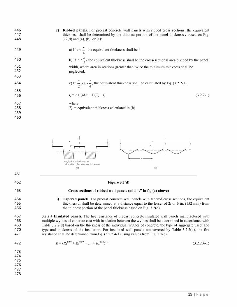
2) Ribbed panels. For precast concrete wall panels with ribbed cross sections, the equivalent 446thickness shall be determined by the thinnest portion of the panel thickness t based on Fig. 4473.2(d) and (a), (b), or (c): 448
a) If 4st £ , the equivalent thickness shall be t. 449
b) If 2st ³ , the equivalent thickness shall be the cross-sectional area divided by the panel 450
width, where area in sections greater than twice the minimum thickness shall be 451neglected. 452
453
c) If 42sts
>> , the equivalent thickness shall be calculated by Eq. (3.2.2-1). 454
455te = t + (4t/s – 1)(Te – t) (3.2.2-1) 456
where 457Te = equivalent thickness calculated in (b) 458
459 460
461
Figure 3.2(d) 462
Cross sections of ribbed wall panels (add “s” in fig (a) above) 463
3) Tapered panels. For precast concrete wall panels with tapered cross sections, the equivalent 464thickness te shall be determined at a distance equal to the lesser of 2t or 6 in. (152 mm) from 465the thinnest portion of the panel thickness based on Fig. 3.2(d). 466
3.2.2.4 Insulated panels. The fire resistance of precast concrete insulated wall panels manufactured with 467multiple wythes of concrete cast with insulation between the wythes shall be determined in accordance with 468Table 3.2.2(d) based on the thickness of the individual wythes of concrete, the type of aggregate used, and 469type and thickness of the insulation. For insulated wall panels not covered by Table 3.2.2(d), the fire 470resistance shall be determined from Eq. (3.2.2.4-1) using values from Fig. 3.2(e). 471
R = (R10.59 + R2
0.59 + … + Rn0.59)1.7 (3.2.2.4-1) 472
473 474 475 476 477 478
Neglect shaded area incalculation of equivalent thickness
t2t
s
te t
(a) (b)

20|P a g e
479 480 481 482Table 3.2.2(d) Fire endurance of precast concrete insulated panels 483
Inside wythe Thickness in in. (mm)
Insulation Thickness in in. (mm)
Outside wythe Thickness in in. (mm)
Fire Endurance Hour:minutes
1 ½ (38) Siliceous aggregate 1 ½ (38) Carbonate aggregate 1 ½ (38) Sand-lightweight1
2 (51) Siliceous aggregate 2 (51) Carbonate aggregate 2 (51) Sand-lightweight1
3 (76) Siliceous aggregate
1 (25) cellular plastic2
1 (25) cellular plastic2
1 (25) cellular plastic2
1 (25) cellular plastic2
1 (25) cellular plastic2
1 (25) cellular plastic2
1 (25) cellular plastic2
1 ½ (38) Siliceous aggregate 1 ½ (38) Carbonate aggregate 1 ½ (38) Sand-lightweight1
2 (51) Siliceous aggregate 2 (51) Carbonate aggregate 2 (51) Sand-lightweight1
3 (76) Siliceous aggregate
1:23 1:23 1:45 1:50 2:00 2:32 3:07
1 ½ (38) Siliceous aggregate 2 (51) Siliceous aggregate 2 (51) Sand-lightweight1
2 (51) Siliceous aggregate
¾ (19) glass fiber board ¾ (19) glass fiber board ¾ (19) glass fiber board ¾ (19) glass fiber board
1 ½ (38) Siliceous aggregate 2 (51) Siliceous aggregate 2 (51) Sand-lightweight1
3 (76) Siliceous aggregate
1:39 2:07 2:52 3:10
1 ½ (38) Siliceous aggregate 2 (51) Siliceous aggregate 2 (51) Sand-lightweight1
1 ½ (38) glass fiber board 1 ½ (38) glass fiber board 1 ½ (38) glass fiber board
1 ½ (38) Siliceous aggregate 2 (51) Siliceous aggregate 2 (51) Sand-lightweight1
2:35 3:08 4:00
1 ½ (38) Siliceous aggregate 1 ½ (38) Sand-lightweight1
2 (51) Carbonate aggregate 2 (51) Sand-lightweight1
1 (25) insulating concrete3
1 (25) insulating concrete3
1 (25) insulating concrete3
1 (25) insulating concrete3
1 ½ (38) Siliceous aggregate 1 ½ (38) Sand-lightweight1
2 (51) Carbonate aggregate 2 (51) Sand-lightweight1
2:12 2:39 2:56 3:33
1 ½ (38) Siliceous aggregate 1 ½ (38) Sand-lightweight1
2 (51) Siliceous aggregate
1 ½ (38) insulating concrete3
1 ½ (38) insulating concrete3
1 ½ (38) insulating concrete3
1 ½ (38) Siliceous aggregate 1 ½ (38) Sand-lightweight1
3 (76) Siliceous aggregate
2:54 3:24 4:16
2 (51) Siliceous aggregate 1 ½ (38) Sand-lightweight1
2 (51) insulating concrete3
2 (51) insulating concrete3 2 (51) Siliceous aggregate 1 ½ (38) Sand-lightweight1
4:25 4:19
1115 lb/ft3 maximum (1842 kg/m3) 4842Polystyrene or polyurethane 485335 lb/ft3 maximum (561 kg/m3) 486
487
488
489

21|P a g e
490
R, minutes R0.59 60 11.20 120 16.85 180 21.41 240 25.37 Material R0.59 Cellular plastic (1 in. or thicker) 2.57 ¾ in. thick glass fiber board 4.03 1½ in. thick glass fiber board 8.57 Continuous air space 3.33 Two continuous air spaces 6.67
491
Figure 3.2(e) 492
Design aid for Eq. 3.2.2.4-1 493
Note: 1 in. = 25.4 mm. 494
495
THICKNESS OF ONE COURSE, in.
R0.
59 F
OR
USE
IN E
Q. 8
.2
Insu
lating
con
cret
e (3
5 lb
/ft³)
Lightw
eight
conc
rete
Sand-lig
htweig
ht co
ncret
e
Carbonate aggregate concrete
Siliceous a
ggregate concrete
1 2 3 4 50
20
15
10
5

22|P a g e
3.2.3 Beams. The fire resistance for concrete beams shall be determined in accordance with 3.2.3.1 through 4963.2.3.3. Alternatively, the provisions of 2.5.2 shall be permitted. 497
3.2.3.1 Restrained beam reinforcement cover. The positive moment reinforcement for all 498prestressed concrete beams that meet the requirements for restrained conditions in 2.4.1 shall be 499provided with concrete cover in accordance with Table 3.2.3(a) or 3.2.3(b), based on aggregate type 500and beam width or beam cross-sectional area. Where differences in values between Tables 3.2.3(a) 501and 3.2.3(b) occur, the smaller value is permitted to be used. The positive moment reinforcement 502for all reinforced concrete beams that meet the requirements for restrained conditions in 2.4.1 shall 503be provided with concrete cover in accordance with Table 3.2.3(c), based on beam width. 504
3.2.3.2 Unrestrained beam reinforcement cover. The positive moment reinforcement for all 505prestressed concrete beams that do not meet the requirements for restrained conditions in 2.4.1 shall 506be provided with concrete cover in accordance with Table 3.2.3(d) or 3.2.3(e), based on aggregate 507type and beam width or beam cross-sectional area. Where differences in values between Tables 5083.2.3(d) and 3.2.3(e) occur, the smaller value is permitted to be used. The positive moment 509reinforcement for all reinforced concrete beams that do not meet the requirements for restrained 510conditions in 2.4.1 shall be provided with concrete cover in accordance with Table 3.2.3(f), based 511on beam width. 512
3.2.3.3 Determining reinforcement cover for concrete beams. The concrete cover for prestressing 513tendons shall be determined in accordance with 3.2.3.3.1. The concrete cover for nonprestressed 514reinforcement shall be determined in accordance with 3.2.3.3.2. 515
3.2.3.3.1 Prestressing tendon cover 516
a) For an individual tendon, the cover is the distance between the surface of the individual 517tendon and the nearest fire-exposed surface of the beam. 518
b) For an ungrouted duct, the cover is the distance between the surface of the duct and the 519fire-exposed surface of the beam. 520
c) For beams with two or more tendons, the cover is the average of the minimum distances 521between the individual tendons and the fire-exposed surface of the beam. 522
d) The cover for corner tendons with equal spacing to the bottom and side, shall be one half 523of the actual distance between the surface of the tendon and the fire exposed surface of the 524beam. 525
e) For stemmed members with two or more tendons located vertically along the center of the 526stem, the cover is the average distance from the centroid of the tendons to the bottom of 527the stem. 528
f) For any one tendon, the actual cover shall not be less than one half of the smaller values in 529Tables 3.2.3(a), 3.2.3(b), 3.2.3(d), or 3.2.3(e) but at least 1 in. (25 mm). 530
3.2.3.3.2 Nonprestressed reinforcement cover 531
a) For an individual reinforcement bar, the cover is the distance between the surface of the 532individual bar and the nearest fire-exposed surface of the beam. 533
b) The cover for corner bars shall be one half of the actual distance between the surface of the 534bar and the fire exposed surface of the beam. 535

23|P a g e
c) For any one bar, the actual cover shall not be less than one half of the smaller value in 536Tables 3.2.3(c) or 3.2.3(f), but at least 3/4 in. (19 mm). 537
Table 3.2.3(a) Concrete cover for restrained prestressed beams 8 in. (203 mm) or greater in width 538
Fire resistance,
hours
Concrete cover for restrained prestressed beams, in. (mm) Siliceous or carbonate Sand-lightweight, lightweight
Beam width = 8 in. (203 mm)*
Beam width ≥12 in. (305 mm)
Beam width = 8 in. (203 mm)*
Beam width ≥ 12 in. (305 mm)
1 1½ (38) 1½ (38) 1½ (38) 1½ (38) 1½ 1½ (38) 1½ (38) 1½ (38) 1½ (38) 2 1½ (38) 1½ (38) 1½ (38) 1½ (38) 3 1¾† (44) 1½ (38) 1½ (38) 1½ (38) 4† 2½† (64) 1 7/8† (48) 2† (51) 1 5/8† (41)
* Direct interpolation for minimum cover is permitted for beam widths between 8 and 12 in. (203 and 305 mm) †Values are based on beams spaced at more than 4 ft (1219 mm) on center. For beam spacings less than 4 ft (1219 mm) on center, the minimum concrete cover is permitted to be reduced to ¾ in. (19 mm) for 4 hour ratings or less.
539
540
Table 3.2.3(b) Concrete cover for restrained prestressed beams of all widths 541
Fire resistance,
hours
Concrete cover for restrained prestressed beams, in. (mm)* Siliceous or carbonate Sand-lightweight All aggregate
150 in.2 < A† ≤ 300 in.2 (96700 mm2 < A ≤
194000 mm2)
300 in.2 < A† (194000 mm2 <
A)
150 in.2 < A† (96700 mm2 < A)
40 in.2 ≤ A† ≤ 150 in.2 (25800 mm2 ≤ A ≤
96700 mm2) 1 1½ (38) 1½ (38) 1½ (38) 1½ (38)
1½ 1½ (38) 1½ (38) 1½ (38) 1½ (38) 2 1½ (38) 1½ (38) 1½ (38) 2 (51) 3 1 3/4 (44) 1½ (38) 1½ (38) 2½ (64) 4 2½ (64) 2 (51) 2 (51) n/a
Note: n/a = not applicable. * Values are based on beams spaced at more than 4 ft (1219 mm) on center. For beam spacings less than 4 ft (1219 mm) on center, the minimum concrete cover is permitted to be reduced to ¾ in. (19 mm) for 4 hour ratings or less. †A = beam area, in.2 (mm2) A portion of the flange is permitted to be included in the cross-sectional area of a stem where the width of the flange included in the area calculation does not exceed three times the average width of the stem.
542
543
Table 3.2.3(c) Concrete cover for restrained concrete beams 544
Fire resistance, hours Concrete cover for restrained concrete beams, in. (mm) Beam width = 5 in.
(127 mm)* Beam width = 7 in.
(178 mm)* Beam width ≥ 10 in.
(254 mm)* 1 ¾ (19) ¾ (19) ¾ (19)
1½ ¾ (19) ¾ (19) ¾ (19) 2 ¾ (19) ¾ (19) ¾ (19) 3 1† (25) ¾ (19) ¾ (19) 4 1¼† (32) ¾ (19) ¾ (19)
* Direct interpolation for minimum cover is permitted for beam widths between the values shown. † Values are based on beams spaced at more than 4 ft (1219 mm) on center. For beam spacings less than 4 ft (1219 mm) on center, the minimum concrete cover is permitted to be reduced to ¾ in. (19 mm) for 4 hour ratings or less.
545

24|P a g e
546
Table 3.2.3(d) Concrete cover for unrestrained prestressed beams 8 in. (203 mm) or greater in width 547
Fire resistance,
hours
Concrete cover for unrestrained prestressed beams, in. (mm) Siliceous or carbonate Sand-lightweight, lightweight
Beam width = 8 in. (203 mm)*
Beam width ≥ 12 in. (305 mm)*
Beam width = 8 in. (203 mm)*
Beam width ≥ 12 in. (305 mm)*
1 1½ (38) 1½ (38) 1½ (38) 1½ (38) 1½ 1¾ (44) 1½ (38) 1½ (38) 1½ (38) 2 2½ (64) 1 7/8 (48) 2 (51) 1 5/8 (41) 3 5† (127) 2½ (64) 3¼ (83) 2 (51) 4 n/a 3 (76) n/a 2½ (64)
Note: n/a = not applicable. * Direct interpolation for minimum cover is permitted for beams between 8 and 12 in. (203 and 305 mm). † This value is not possible for 8 in. (203 mm) beam widths but is shown for interpolation purposes.
548
549
Table 3.2.3(e) Concrete cover for unrestrained prestressed beams of all widths 550
Fire resistance,
hours
Concrete cover for unrestrained prestressed beams, in. (mm) Siliceous or carbonate Sand-lightweight All aggregate
150 in.2 < A* ≤ 300 in.2 (96700 mm2 < A ≤
194000 mm2)
300 in.2 < A*
(194000 mm2 < A)
150 in.2 < A* (96700 mm2 < A)
40 in.2 ≤ A* ≤ 150 in.2 (25800 mm2 ≤ A ≤
96700 mm2) 1 1½ (38) 1½ (38) 1½ (38) 2 (51)
1½ 1¾ (44) 1½ (38) 1½ (38) 2½ (64) 2 2½ (64) 2 (51) 2 (51) n/a 3 n/a 3† (76) 3† (76) n/a 4† n/a 4† (102) 4† (102) n/a
Note: n/a = not applicable. * A = beam area, in.2 (mm2) A portion of the flange is permitted to be included in the cross-sectional area of a stem where calculation does not exceed three times the average width of the stem. † U-shaped or hooped stirrups spaced not to exceed the depth of the beam with a minimum cover of 1 in. (25 mm) shall be provided.
551
552
Table 3.2.3(f) Concrete cover for unrestrained concrete beams 553
Fire resistance, hours
Concrete cover for unrestrained concrete beams, in. (mm) Beam width = 5 in.
(127 mm)* Beam width = 7 in.
(178 mm)* Beam width ≥ 10 in.
(254 mm)* 1 ¾ (19) ¾ (19) ¾ (19)
1½ 1 (25) ¾ (19) ¾ (19) 2 1¼ (32) ¾ (19) ¾ (19) 3 n/a 1¾ (44) 1 (25) 4 n/a 3 (76) 1¾ (44)
Note: n/a = not applicable. * Direct interpolation for minimum cover is permitted for beam widths between the values shown.
554
555
3.2.4 Floor and roof slabs. The fire resistance for precast concrete floor and roof slabs shall be determined 556in accordance with 3.2.4.1 through 3.2.4.4. Alternatively, the provisions of 2.5.2 shall be permitted. 557

25|P a g e
3.2.4.1 Solid single-course slabs. The fire resistance of solid precast concrete slabs shall be 558determined in accordance with Table 3.2.2(a) based on the thickness of the concrete and the 559aggregate used for the concrete mixture. 560
3.2.4.1.1 Nonuniform thickness slabs. The equivalent thickness te of nonuniform slabs 561shall be determined in accordance with 3.2.2.3. 562
3.2.4.1.2 Additional component layers. If the underside of the precast concrete slab is 563provided with an additional layer of 5/8 in. (16 mm) thick Type X gypsum board on the 564fire-exposed side of the slab, the fire resistance shall be permitted to be determined in 565accordance with Fig. 3.2.4(a) based on the thickness of the concrete, the aggregate used for 566the concrete mixture, and the depth of the air space between the slab and the gypsum board. 567If vermiculite cementitious material, sprayed mineral fiber, or intumescent mastics are 568applied to the precast concrete element, the concrete thickness shall be permitted to be 569increased based on the values in Fig. 3.2.4(b). 570
571
572
Figure 3.2.4(a) 573Fire endurance of single-course floor slab. 574
Note: 1 in. = 25.4 mm. 575
576
577
5/8 in. thick type X gypsum wallboard6 in. thick air space
CONCRETE SLAB THICKNESS, in.
FIRE
END
URAN
CE, h
rFI
RE E
NDUR
ANCE
, hr
5/8 in. thick type X gypsum wallboard7/8 in. thick air space
Sand-lightweight
Siliceous aggregate concrete
Carbonate
Sand-lightweight
Siliceous aggregate concreteCarbonate
02 3 4
1
2
3
4
02 3 4
1
2
3
4

26|P a g e
578
Figures 3.2.4(b) 579Equivalent concrete cover with vermiculite cementitious material, 580
sprayed mineral fiber, or intumescent mastics. 581Note: 1 in. = 25.4 mm. 582
583 584
3.2.4.2 Multi-course floor slabs. The fire resistance of precast concrete floor slabs provided with 585an additional course of lightweight concrete, cellular concrete, perlite concrete, vermiculite 586concrete, vermiculite cementitious material, sprayed mineral fiber, or intumescent mastics shall be 587determined in accordance with Fig. 3.2.4(c) through 3.2.4(e) based on the thickness of the concrete, 588the aggregate used for the concrete mixture and the type and location of the added course. 589
3.2.4.3 Multi-course roof slabs. The fire resistance of precast concrete roof slabs provided with an 590additional course of mineral board or glass fiber board shall be determined in accordance with Fig. 5913.4.1(f) based on the thickness of the concrete, the aggregate used for the concrete mixture and the 592type and location of the added course. 593
5
4
3
2
1
00 0.25 0.5 0.75
Intu
mes
cent
mas
tic
(for 2
hr o
r les
s)
1 1.25 1.5
EQUI
VALE
NT C
ONC
RETE
CO
VER
THIC
KNES
S, in
.
THICKNESS OF SPRAY-APPLIED INSULATING MATERIAL, in.
Vermiculite
cementitious m
aterial (VCM) (slabs)
Sprayed mineral fiber (S
MF) (slabs)
VCM or SMF (joists)

27|P a g e
594
Figure 3.2.4(c) 595Fire endurance of multi-course floor slab with normalweight and lightweight concrete. 596
Note: 1 in. = 25.4 mm. 597
THICKNESS OF SAND-LIGHTWEIGHT CONCRETE BASE SLAB, in.(b)
OVE
RLAY
THI
CKNE
SS, i
n.TH
ICKN
ESS
OF
SAND
-LIG
HTW
EIG
HTCO
NCRE
TE O
VERL
AY, i
n.
THICKNESS OF NORMALWEIGHT CONCRETE BASE SLAB, in.(a)
LIGHTWEIGHT CONCRETE
NORMALWEIGHT CONCRETE
NORMALWEIGHT CONCRETE
LIGHTWEIGHT CONCRETE
CARB. BASE SIL. BASE
CARB. OVERLAY SIL. OVERLAY
1 hr
2 hr
3 hr4 hr
3
2
1
41 320
5
4
5
3
2
1
41 320
5
4
5
3
2
1
41 320
5
4
5
3
2
1
41 320
5
4
5
1 hr
2 hr
3 hr4 hr
1 hr
2 hr
3 hr4 hr
1 hr
2 hr3 hr
4 hr

28|P a g e
598
Figure 3.2.4(d) 599Fire endurance of multi-course floor slab with normalweight concrete and vermiculite 600
cementitious material, sprayed mineral fiber, or intumescent mastics. 601
Note: 1 in. = 25.4 mm. 602
CONCRETE
THICKNESS OF CONCRETE BASE SLAB, in.(c)
THIC
KNES
S O
F IN
TUM
ESCE
NT M
ASTI
C, in
.TH
ICKN
ESS
OF
SPRA
YED
MIN
ERAL
FIB
ER, i
n.TH
ICKN
ESS
OF
VERM
ICUL
ITE
TYPE
MK,
in.
THICKNESS OF CONCRETE BASE SLAB, in.(b)
THICKNESS OF CONCRETE BASE SLAB, in.(a)
CARB. SIL. SLW
CARB. SIL. SLW
CARB. SIL. SLW
CONCRETE
VERMICULITE C.M.
CONCRETE
SPRAYED MINERAL FIBER
CONCRETE
INTUMESCENT MASTIC
1.5
1.0
0.5
51 30
1.5
1.0
0.5
51 30
1.5
1.0
0.5
51 30
1.2
0.8
0.4
51 30
1.2
0.8
0.4
51 30
1.2
0.8
0.4
51 30
0.2
51 30
0.4
0.2
51 30
0.4
0.2
51 30
0.4
1 hr
2 hr3 hr
4 hr
1 hr
2 hr
3 hr4 hr
1 hr
2 hr
3 hr4 hr
1 hr
2 hr3 hr
4 hr
1 hr
2 hr3 hr
4 hr
1 hr
2 hr3 hr
4 hr
1 hr
2 hr
3 hr
1 hr
2 hr
3 hr
1 hr
2 hr
3 hr

29|P a g e
603
Figure 3.2.4(e) 604Fire endurance of multi-course floor slab with normalweight concrete and cellular, 605
vermiculate, or perlite concrete. 606
Note: 1 in. = 25.4 mm. 607
THICKNESS OF CONCRETE BASE SLAB, in.(c)
THIC
KNES
S O
F VE
RMIC
ULIT
ECO
NCRE
TE O
VERL
AY, i
n.TH
ICKN
ESS
OF
PERL
ITE
CONC
RETE
OVE
RLAY
, in.
THIC
KNES
S O
F CE
LLUL
ARCO
NCRE
TE O
VERL
AY, i
n.
THICKNESS OF CONCRETE BASE SLAB, in.(b)
THICKNESS OF CONCRETE BASE SLAB, in.(a)
CARB. BASE SIL. BASE SLW
CARB. BASE SIL. BASE SLW
CARB. BASE SIL. BASE SLW
CELLULAR CONCRETE
CONCRETE
PERLITE CONCRETE
CONCRETE
VERMICULITE CONCRETE
CONCRETE
3
2
1
40 2
3
2
1
40 2
3
2
1
40 2
3
2
1
40 2
4
3
2
1
40 2
4
3
2
1
40 2
4
3
2
1
40 2
4
3
2
1
40 2
4
3
2
1
40 2
4
1 hr
2 hr3 hr
4 hr
1 hr2 hr
3 hr4 hr
1 hr2 hr
3 hr4 hr
1 hr
2 hr3 hr
4 hr
1 hr
2 hr3 hr
4 hr
1 hr
2 hr3 hr
4 hr
1 hr
2 hr3 hr
4 hr
1 hr
2 hr3 hr
4 hr
1 hr2 hr
3 hr4 hr

30|P a g e
608
Figure 3.2.4(f) 609Fire endurance of multi-course roof slab with normalweight concrete and 610
mineral board or glass fiber board. 611
Note: 1 in. = 25.4 mm. 612
THICKNESS OF CONCRETE BASE SLAB, in.(b)
THIC
KNES
S O
F G
LASS
FIB
ER B
OAR
D, in
.TH
ICKN
ESS
OF
MIN
ERAL
BO
ARD,
in.
THICKNESS OF CONCRETE BASE SLAB, in.(a)
MINERAL BOARD
CONCRETE
GLASS FIBER BOARD
CONCRETE
CARB. BASE SIL. BASE SLW BASE
CARB. BASE SIL. BASE SLW BASE
STANDARD 3-PLYBUILT-UP ROOFING
STANDARD 3-PLYBUILT-UP ROOFING
1 hr
2 hr3 hr
4 hr
3
2
1
41 320
3
2
1
41 320
3
2
1
41 320
3
2
1
41 320
5
3
2
1
41 320
5
3
2
1
41 320
5
3
2
1
41 320
5
1 hr
2 hr3 hr
4 hr
1 hr
2 hr3 hr
4 hr
1 hr
2 hr3 hr
4 hr
1 hr
2 hr3 hr
4 hr
1 hr
2 hr3 hr
4 hr

31|P a g e
3.2.4.4 Slab reinforcement cover. The reinforcement for all precast, prestressed or cast-in-place 613concrete slabs that meet the requirements for restrained conditions in 2.4.1 shall be provided with a 614minimum of ¾ in. (19 mm) of concrete cover for fire resistance ratings up to four hours. The 615reinforcement for all precast, prestressed concrete slabs that do not meet the requirements for 616restrained conditions in 2.4.1 shall be provided with concrete cover in accordance with Table 6173.2.4(a). The reinforcement for all nonprestressed slabs that do not meet the requirements for 618restrained conditions in 2.4.1 shall be provided with concrete cover in accordance with Table 6193.2.4(b). 620
Table 3.2.4(a) Concrete cover for unrestrained prestressed slabs 621
Fire resistance, hours Concrete cover for unrestrained prestressed slabs, in. (mm) Siliceous Carbonate Sand-lightweight, lightweight
1 1 1/8 (29) 1 (25) 1 (25) 1½ 1½ (38) 1 3/8 (35) 1 3/8 (35) 2 1¾ (44) 1 5/8 (41) 1½ (38) 3 2 3/8 (60) 2 1/8 (54) 2 (51) 4 2¾ (70) 2¼ (57) 2¼ (57)
622
Table 3.2.4(b) Concrete cover for unrestrained nonprestressed slabs 623
Fire resistance, hours Concrete cover for unrestrained nonprestressed slabs, in. (mm) Siliceous Carbonate Sand-lightweight, lightweight
1 ¾ (19) ¾ (19) ¾ (19) 1½ ¾ (19) ¾ (19) ¾ (19) 2 1 (25) ¾ (19) ¾ (19) 3 1¼ (32) 1¼ (32) 1¼ (32) 4 1 5/8 (41) 1¼ (32) 1¼ (32)
624
3.2.4.4.1 Determining reinforcement cover for slabs. The concrete cover to 625reinforcement shall be determined in accordance with 3.2.3.3 626
3.3—Rational design for slabs and beams. Precast concrete slabs and beams designed in accordance with 3.3.1 627through 3.3.5 shall demonstrate that sectional strength considering concrete and steel material properties at elevated 628temperatures is greater than or equal to the load effects at the required fire resistance. Except as permitted by the 629building code, minimum thickness requirements in 3.2.4.1 through 3.2.4.3 for heat transmission shall be satisfied. 630
3.3.1 Concrete temperature. If the concrete temperature in the compression zone exceeds 900°F (482°C), 631the reduced concrete compressive strength fc¢q shall be used in calculating the value of the depth of the 632equivalent rectangular stress block aɵ. 633
3.3.2 Unrestrained simply supported slabs and beams. For unrestrained simply supported horizontal 634structural members the applied moment M shall not exceed the nominal flexural strength at elevated 635temperature Mnɵ of the member, based on the internal temperature of the concrete and steel for a given fire 636resistance rating. The nominal flexural strength at elevated temperature Mnɵ of the member shall be 637determined in accordance with Eq. (3.3.2-1), (3.3.2-2), and (3.3.2-3). 638
÷ø
öçè
æ -=2q
qa
dfAM pspsn (3.3.2-1) 639
÷÷ø
öççè
æ-= '
5.01
q
qqq
c
pupspups bdf
fAff (3.3.2-2) 640

32|P a g e
bf
fAa
c
psps'85.0 q
qq = (3.3.2-3) 641
642
3.3.3 Restrained simply supported slabs and beams. For restrained simply supported horizontal structural 643members the applied moment M shall not exceed the nominal flexural strength Mnɵ calculated in accordance 644with Eq. (3.3.2-1), (3.3.2.-2), and (3.3.2-3) with the internal temperature of the concrete and steel determined 645at one-half the required fire resistance rating of the restrained member, but not less than 1 hour. 646
3.3.4 Beams and slabs continuous at supports. For horizontal structural members with continuity at 647supports, the applied moment M shall not exceed the nominal flexural strength at elevated temperature Mnɵ 648of the member, based on the internal temperature of the concrete and steel for a given fire resistance rating. 649
3.3.4.1 Positive moment capacity. The positive nominal flexural strength at elevated temperature, 650M+
nq, of the member shall be determined in accordance with Eq. (3.3.2-1). 651
3.3.4.2 Applied positive moment. The applied positive moment M+ shall be the lesser of the simple 652span moment and the positive nominal moment capacity from Eq. (3.3.4-1). 653
++ £= qnMwM8
2! (3.3.4-1) 654
3.3.4.3 Negative moment capacity. The negative nominal flexural strength at elevated temperature 655M-
nq at supports where slabs and beams are continuous shall be determined in accordance with Eq. 656(3.3.2-1). The applied negative moment M- shall not exceed the negative nominal flexural strength 657at elevated temperature M-
nq. 658
3.3.4.4 Applied negative moment. The applied negative moment at supports where slabs and beams 659are continuous shall be determined in accordance with (a) through (c). 660
a) Uniformly loaded member continuous at one support. The applied negative moment at 661the continuous support shall be determined in accordance with Fig. 3.3(a) and Eq. (3.3.4-2) 662through (3.3.4-4). 663664
22
2 22 !
!!
wMwwM
+- ±= (3.3.4-2)665
!!
wMX
-
-=21 (3.3.4-3)666
!wMX
-
=2
0 (3.3.4-4) 667
668 669670
671
672
673

33|P a g e
674
675
Figure 3.3(a) 676Moment diagram for uniformly loaded members continuous at one support. 677
678
b) Uniformly loaded member continuous at two supports. The applied negative moment at 679the continuous support shall be determined in accordance with Fig. 3.3(b) and Eq. (3.3.4-5) 680through (3.3.4-7). 681
+- -= MwM8
2! (3.3.4-5)682
wMX
+
=2
2 (3.3.4-6) 683
( )20 21 XX -= ! (3.3.4-7) 684
685 686
687
688
689
690
691
692
693
694Figure 3.3(b) 695
Moment diagram for uniformly loaded members continuous at both supports. 696 697
c) Other cases. For cases not described in (a) and (b), the applied negative moment at the end 698of a member shall distribute the applied loads based on any reasonable assumptions for member 699stiffness of the structural elements at the design fire conditions. 700
3.3.4.5 Negative moment reinforcement. The design shall consider the amount of and the effects 701of negative reinforcement on moment redistribution to prevent a secondary failure. At least 20% of 702the maximum negative moment reinforcement shall be extended through the length of the span ℓ. In 703addition, negative moment reinforcement shall extend a development length beyond the inflection 704point X calculated using one-half of the required live load. 705
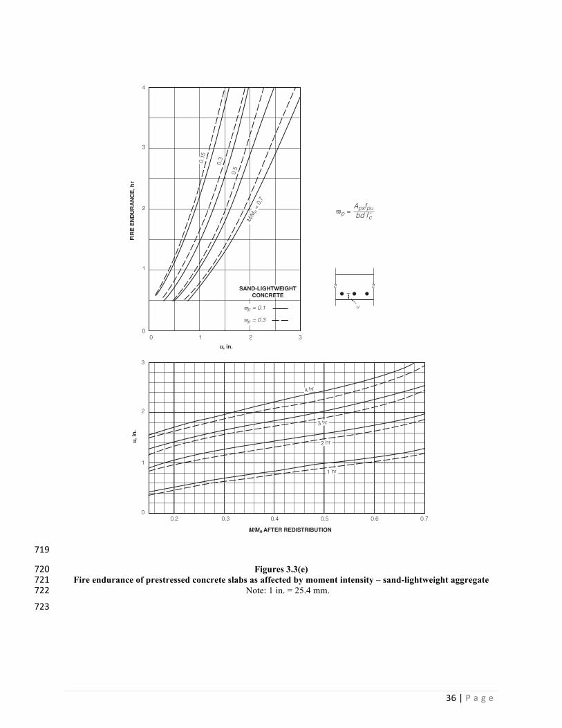
3.3.5 Moment intensity. Figures 3.3(c), 3.3(d) or 3.3(e) shall be permitted to be used to determine the fire 706resistance of slabs and beams based on the moment intensity M/Mn of the design of precast concrete elements 707

34|P a g e
using carbonate, siliceous, and sand-lightweight concrete, respectively. For precast concrete elements wider 708than 10 in. (254 mm), the strands shall be spaced uniformly in horizontal rows and the fire resistance shall 709be based on the effective u, ū. These figures shall not be applied if strands are bundled. 710
711
Figures 3.3(c) 712Fire endurance of prestressed concrete slabs as affected by moment intensity – carbonate aggregate 713
Note: 1 in. = 25.4 mm. 714
4
3
2
1
0
3
24 hr
0.15 0.
3
M/M
n =
0.7
0.5
3 hr
2 hr
1 hr1
0
0 1
0.2 0.3 0.4 0.5 0.6 0.7
2 3
FIRE
END
URAN
CE, h
r
u, in.
CARBONATEAGGREGATE
u, in
.
M/Mn AFTER REDISTRIBUTION
u
Apsfpubd f c
ϖp =
ϖp = 0.1
ϖp = 0.3

35|P a g e
715
Figures 3.3(d) 716Fire endurance of prestressed concrete slabs as affected by moment intensity – siliceous aggregate 717
Note: 1 in. = 25.4 mm. 718
4
3
2
1
0
3
2
4 hr
0.15
0.3
M/M
n =
0.7
0.5
3 hr
2 hr
1 hr1
0
0 1
0.2 0.3 0.4 0.5 0.6 0.7
2 3
FIRE
END
URAN
CE, h
r
u, in.
SILICEOUSAGGREGATE
u, in
.
M/Mn AFTER REDISTRIBUTION
uϖp = 0.1
ϖp = 0.3
Apsfpubd f c
ϖp =
36|P a g e
719
Figures 3.3(e) 720Fire endurance of prestressed concrete slabs as affected by moment intensity – sand-lightweight aggregate 721
Note: 1 in. = 25.4 mm. 722
723
4
3
2
1
0
3
2
4 hr
0.15
0.3
M/Mn
= 0.
7
0.5
3 hr
2 hr
1 hr1
0
0 1
0.2 0.3 0.4 0.5 0.6 0.7
2 3
FIRE
END
URAN
CE, h
r
u, in.
SAND-LIGHTWEIGHTCONCRETE
u, in
.
M/Mn AFTER REDISTRIBUTION
uϖp = 0.1
ϖp = 0.3
Apsfpubd fc
ϖp =

37|P a g e
CHAPTER 4—SPECIAL CONSIDERATIONS 724
7254.1—General The fire resistance design of precast concrete shall include consideration of the effect on fire resistance 726of openings through precast concrete elements and connections between precast concrete elements. Openings shall be 727protected in accordance with 4.2 and connections shall be protected in accordance with 4.3. 728
4.2—Protection of openings. Openings through precast concrete elements required to have a fire resistance by 729poke-thru devices and joints shall be protected to provide the necessary fire resistance of the element. Poke-thru 730devices shall be protected in accordance with 4.2.1. Joints in precast concrete elements shall comply with 4.2.2. 731
4.2.1 Poke-thru devices. Poke-thru devices shall be provided with the protection necessary to achieve the 732required fire resistance in accordance with one of (a) through (e). Approved alternative materials and methods 733shall be permitted. 734
a) Sprayed mineral fiber cover for the required thickness in accordance with Fig. 4.2(a) 735b) Vermiculite cementitious material cover for the required thickness in accordance with Fig. 4.2(b) 736
c) Perlite concrete shield for the required thickness in accordance with Fig. 4.2(c) 737
d) Mineral insulation board shield for the required thickness in accordance with Fig. 4.2(d) 738
e) Mineral wool insulation shield for the required thickness in accordance with Fig. 4.2(e) 739
740
741
742
Figure 4.2(a) Figure 4.2(b) 743
Fittings undercoated with sprayed mineral fiber Fittings undercoated with vermiculite 744
cementitious material 745
Note: °F = (°C × 1.8) + 32; 1 in. = 25.4 mm. 746
THICKNESS OF VERMICULITE CEMENTITIOUS MATERIAL, in.
FIRE
TES
T TI
ME
FOR
325
°FRI
SE O
VER
FITT
ING
, hr
00
2
1
3
(b)
4
1 2
4 in. slab
Toggle-type fitting
Box-type fitting
00
2
1
3
(a)
4
1 2
Toggle-type fitting
Box-type fitting
THICKNESS OF SPRAYED MINERAL FIBER, in.
4 in. slab

38|P a g e
747
748
749
Figure 4.2(c) Figure 4.2(d) 750
Fittings protected with perlite concrete Fittings protected with mineral insulation board 751
Note: °F = (°C × 1.8) + 32; 1 in. = 25.4 mm. 752
753
754
Figure 4.2(e) 755
Fittings protected with mineral wool insulation 756
Note: °F = (°C × 1.8) + 32; 1 in. = 25.4 mm. 757
758
4.2.2 Joints in precast concrete elements. Joints in precast concrete wall, floor, or roof assemblies required 759to have a fire resistance shall be protected in accordance with this section. 760
0
FIRE
TES
T TI
ME
FOR
325
°FRI
SE O
VER
FITT
ING
, hr
00
2
1
3
(c)
4
1 2
THICKNESS OF INSULATION WOOL SHIELD, in.
FIRE
TES
T TI
ME
FOR
325
°FRI
SE O
VER
FITT
ING
, hr
0
2
1
3
(a)
4
1 2
THICKNESS OF PERLITE CONCRETE SHIELD, in.
00
2
1
3
(b)
4
1 2
THICKNESS OF INSULATION BOARD SHIELD, in.
FIRE
TES
T TI
ME
FOR
325
°FRI
SE O
VER
FITT
ING
, hr
00
2
1
3
(d)
4
4 8
SLAB THICKNESS, in.
00
2
1
3
4
Toggle-type fitting
Box-type fitting
Toggle-type fitting
Box-type fitting
Toggle-type fittingBox-type fitting
Toggle-type fitting Box-type fitting
4 in. slab
4 in. slab 4 in. slab
2ʺ PC shield
1ʺ PC shield
2 6 4 82 6
2ʺ PC shield
1ʺ PC shield
0
FIRE
TES
T TI
ME
FOR
325
°FRI
SE O
VER
FITT
ING
, hr
00
2
1
3
(c)
4
1 2
THICKNESS OF INSULATION WOOL SHIELD, in.
FIRE
TES
T TI
ME
FOR
325
°FRI
SE O
VER
FITT
ING
, hr
0
2
1
3
(a)
4
1 2
THICKNESS OF PERLITE CONCRETE SHIELD, in.
00
2
1
3
(b)
4
1 2
THICKNESS OF INSULATION BOARD SHIELD, in.
FIRE
TES
T TI
ME
FOR
325
°FRI
SE O
VER
FITT
ING
, hr
00
2
1
3
(d)
4
4 8
SLAB THICKNESS, in.
00
2
1
3
4
Toggle-type fitting
Box-type fitting
Toggle-type fitting
Box-type fitting
Toggle-type fittingBox-type fitting
Toggle-type fitting Box-type fitting
4 in. slab
4 in. slab 4 in. slab
2ʺ PC shield
1ʺ PC shield
2 6 4 82 6
2ʺ PC shield
1ʺ PC shield

39|P a g e
4.2.2.1 Walls. Joints in walls shall comply with (a) or (b). 761
a) Joints in exterior walls shall be permitted to be included in the allowable area of unprotected 762openings permitted in exterior walls in accordance with the building code. 763
b) Joints in fire-resistant exterior and interior walls that require protection shall be constructed in 764accordance with Fig. 4.2(f), 4.2(g), 4.2(h), or 4.2(i) based on the joint type, joint materials, joint 765width, wall panel thickness, and required fire endurance. 766
767
768
Figure 4.2(f) Figure 4.2(g) 769
Two-stage cavity joint Two-stage shiplap joint 770
Note: 1 in. = 25.4 mm. 771
JOINT WIDTH, in.
FIRE
END
URAN
CE, h
r
0 1/4 1/2 3/40
2
1
4
3
1
7 in. panel
6 in. panel
5 in. panel
4 in. panel
Jointwidth
Panelthickness
Bond breaker
11/4 in. Ceramicfiber blanket
backup rod
Sealant
Sealant
FIRE SIDE
JOINT WIDTH, in.
FIRE
END
URAN
CE, h
r
0 1/4 1/2 3/40
2
1
4
3
1
6 in. panel
5 in. panel
4 in. panel
Panel thicknessBond breaker
11/2 in. ceramicfiber blanket
Backup rodSealant Sealant
Joint width FIRE
SIDE

40|P a g e
772
Figure 4.2(h) 773
Sealant and backer rod joints 774
Note: 1 in. = 25.4 mm. 775
JOINT WIDTH, in.
FIRE
END
URAN
CE, h
r
0 1/4 1/2 3/40
2
1
3
1
6 in. panel
5 in. panel-shiplap joint
5 in. panel4 in. panel
Panel thicknessBackup rod
Sealant Sealant
Joint width FIRE
SIDE
Backup rod
Panelthickness
backup rodSealant
FIRE SIDE
Jointwidth
BUTT JOINT
SHIPLAP JOINT
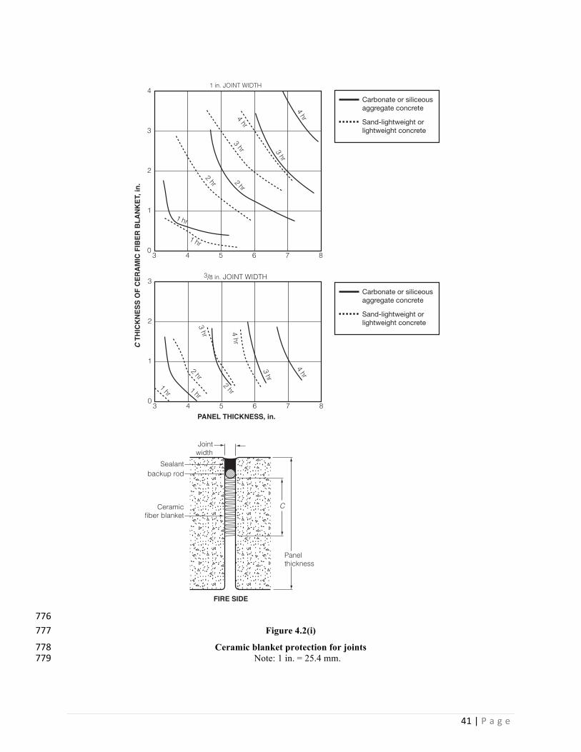
41|P a g e
776Figure 4.2(i) 777
Ceramic blanket protection for joints 778Note: 1 in. = 25.4 mm. 779
C T
HICK
NESS
OF
CERA
MIC
FIB
ER B
LANK
ET, i
n.
3 4 5 860
2
1
4
3
7
PANEL THICKNESS, in.3 4 5 860
2
1
3
7
1 in. JOINT WIDTH
3/8 in. JOINT WIDTH4 hr
3 hr
2 hr
1 hr
4 hr
3 hr
1 hr
1 hr
1 hr
2 hr
2 hr
3 hr 4 hr
2 hr
3 hr4 hr
Carbonate or siliceousaggregate concrete
Sand-lightweight or lightweight concrete
Carbonate or siliceousaggregate concrete
Sand-lightweight or lightweight concrete
Panelthickness
Ceramicfiber blanket
backup rodSealant
FIRE SIDE
Jointwidth
C

42|P a g e
780
4.2.2.2 Slabs. Joints in floor and roof slabs shall comply with one of (a) through (c). 781
a) Joints in slabs shall be permitted to be unprotected in accordance with the building code. 782
b) 1 in. (25 mm) minimum thickness of concrete topping over the joint. 783
c) Grout to a depth of at least 1 in. (25 mm), but not less than one third of the thickness of the slab 784at the joint. 785
4.3—Protection of connections. Connections for precast concrete elements shall meet the lesser required fire 786resistance of the elements being connected. Connections for precast concrete elements required to have a fire resistance 787shall be protected to provide the necessary fire resistance of the element. 788
Exception: Verification of connection fire resistance by testing shall be permitted. 789
4.3.1 Structural steel brackets. Exposed steel brackets that serve as connections for fire-resistant precast 790concrete elements that will be weakened by fire exposure and affect the stability of the structure shall be 791protected to the same degree as that required for the lesser fire resistance of the precast concrete element 792or the supporting member. The exposed steel brackets shall be protected with sprayed mineral fiber, 793vermiculite cementitious material, or intumescent mastics in accordance with Fig. 4.3(a), or dry-packed 794concrete or mortar in accordance with Fig. 4.3(b). Approved alternative methods shall be permitted. 795
796
Figure 4.3(a) Figure 4.3(b) 797
Fire protection for steel brackets Concrete or mortar protection for steel brackets 798
Note: 1 in. = 25.4 mm. 799
800
4.3.2 Ledges, pockets, and concrete corbels. Ledges, pockets, or concrete corbels integral with a precast 801concrete element supporting other elements shall not require additional protection if the element providing the 802support is designed to the required fire resistance. 803
FIRE ENDURANCE, hr
THIC
KNES
S O
F PR
OTE
CTIO
N M
ATER
IAL,
in.
10
2
1
3
4
2 3 4
CONCRETE OR DRY-PACK MORTAR
b ≥ 12 in.
b = 8 in.
(b)(a)
10
2
1
3
4
2 3 4
t = 5 /16
in. S
MF
t = 11/16 in.
IM
SMF or VCM
t = 5/16 in.
t = 5/16 in. VCM

43|P a g e
804 805