PCI-6870 series
128
PCI-6870 series Socket 370 Pentium ® III/Celeron™ Half-sized CPU Card with High Speed PCI Bus, VGA, Fast Ethernet and CompactFlash Type II card
Transcript of PCI-6870 series

PCI-6870 seriesSocket 370 Pentium® III/Celeron™Half-sized CPU Card with High SpeedPCI Bus, VGA, Fast Ethernet andCompactFlash Type II card

PCI-6870 User's Manual i i
Copyright NoticeThis document is copyrighted, 2002. All rights are reserved. Theoriginal manufacturer reserves the right to make improvements to theproducts described in this manual at any time without notice.
No part of this manual may be reproduced, copied, translated ortransmitted in any form or by any means without the prior writtenpermission of the original manufacturer. Information provided in thismanual is intended to be accurate and reliable. However, the originalmanufacturer assumes no responsibility for its use, nor for anyinfringements upon the rights of third parties which may result from itsuse.
AcknowledgementsAward is a trademark of Award Software International, Inc.IBM, PC/AT, PS/2 and VGA are trademarks of International BusinessMachines Corporation.Intel and Pentium are trademarks of Intel Corporation.Microsoft Windows® is a registered trademark of Microsoft Corp.UMC is a trademark of United Microelectronics Corporation.
All other product names or trademarks are properties of theirrespective owners.
For more information on this and other Advantech products pleasevisit our website at: http://www.advantech.com
http://www.advantech.com/epc
For technical support and service for please visit our support websiteat: http://www.advantech.com/support
This manual is for the PCI-6870 Series Rev. A1
Part No. 2006687000 1st EditionPrinted in Taiwan September, 2002

i i i Preface and Table of Contents
Packing List
Before installing your board, ensure that the following materials havebeen received:
• 1 ea. PCI-6870 SBC
• 1 ea. Keyboard/Mouse cable (1700060202)
• 1 ea. COM port cable (1700100250)
• 1 ea. EIDE HDD cable (1700260250)
• 1 ea. Power cable (1703080101)
• 1 ea. Startup Manual
• 1 ea. CD (Driver & utility)
• 1 ea. Warranty card
Note 1: For detailed contents of the PCI-6870 series, please refer to theenclosed CD-ROM or disk (in PDF format).
If any of these items are missing or damaged, contact your distributoror sales representative immediately.
Optional Devices• 1759209100 Fan/Heatsink module
• 9689000042 IrDA adapter
• 1700100170 USB cable adapter

PCI-6870 User's Manual i v
ContentsChapter 1 General Information ......................................... 1
1.1 Introduction................................................................................. 21.2 Specifications .............................................................................. 31.3 Features ...................................................................................... 51.4 Board layout: Dimensions .......................................................... 6
Chapter 2 Installation ......................................................... 72.1 Safety Precautions ...................................................................... 82.2 Jumpers ...................................................................................... 82.3 Connectors .................................................................................. 9
2.3.1 Locating Jumpers and Connectors ....................................102.4 Setting jumpers ........................................................................ 11
2.4.1 COM2 settings for RS-232/422/485 (J3) ............................. 132.4.2 CMOS clear function (J4) ..................................................132.4.3 Watchdog timer config. (J5) ............................................... 132.4.4 Hardware Reset (J6) ........................................................... 132.5.1 IR Connector (CN1) ........................................................... 142.5.2 VGA Display Connector (CN2) ......................................... 14
2.5 Installation Caution ................................................................... 152.5.3 RS-232 connection (COM1-CN3) ......................................152.5.4 Keyboard & PS/2 Mouse Connector (CN4) ...................... 152.5.5 ATX Feature Connector (CN6) ..........................................152.5.6 Parallel Port Connector (CN7) ............................................162.5.7 RS-232/422/485 connection (COM2-CN8) .........................162.5.8 USB Connector (CN9) .......................................................172.5.9 EBX Power Connector (CN11) ...........................................172.5.10 CPU Fan Power Supply Connector (CN12) ..................... 172.5.11 ATX power button (CN13) .............................................. 172.5.12 Ethernet Configuration (CN14) ........................................ 182.5.13 Primary EIDE Connector (CN15) ......................................182.5.14 Serial IRQ ???? (CN16) ..................................................... 192.5.15 Audio connector (CN17) .................................................192.5.16 EIDE, CDROM, HDD connector (CN18) ..........................192.5.17 Video Expansion Connector ???? (CN19) ........................202.5.18 Floppy Drive Connector (CN20) ......................................202.5.19 CompactFlash Disk (SK1) ................................................20
miles.odonnol
miles.odonnol
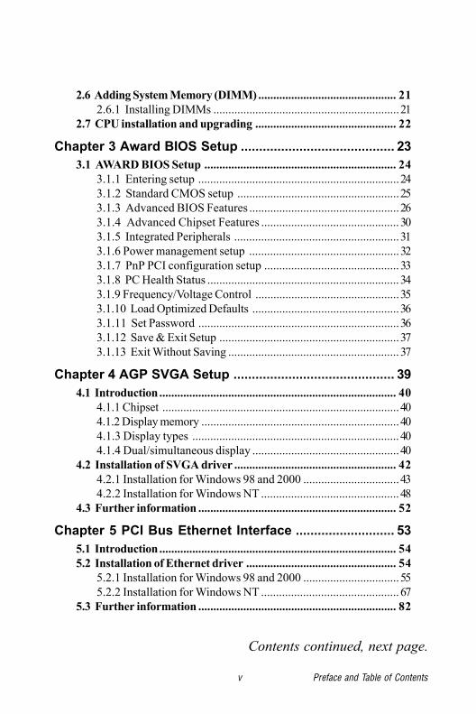
v Preface and Table of Contents
Contents continued, next page.
2.6 Adding System Memory (DIMM).............................................. 212.6.1 Installing DIMMs ..............................................................21
2.7 CPU installation and upgrading ............................................... 22
Chapter 3 Award BIOS Setup .......................................... 233.1 AWARD BIOS Setup ................................................................ 24
3.1.1 Entering setup ...................................................................243.1.2 Standard CMOS setup ......................................................253.1.3 Advanced BIOS Features ..................................................263.1.4 Advanced Chipset Features .............................................. 303.1.5 Integrated Peripherals .......................................................313.1.6 Power management setup ..................................................323.1.7 PnP PCI configuration setup ............................................. 333.1.8 PC Health Status ................................................................ 343.1.9 Frequency/Voltage Control ................................................353.1.10 Load Optimized Defaults .................................................363.1.11 Set Password ...................................................................363.1.12 Save & Exit Setup ............................................................373.1.13 Exit Without Saving ......................................................... 37
Chapter 4 AGP SVGA Setup ............................................ 394.1 Introduction............................................................................... 40
4.1.1 Chipset ...............................................................................404.1.2 Display memory ..................................................................404.1.3 Display types ..................................................................... 404.1.4 Dual/simultaneous display .................................................40
4.2 Installation of SVGA driver ...................................................... 424.2.1 Installation for Windows 98 and 2000 ................................434.2.2 Installation for Windows NT .............................................. 48
4.3 Further information .................................................................. 52
Chapter 5 PCI Bus Ethernet Interface ........................... 535.1 Introduction............................................................................... 545.2 Installation of Ethernet driver .................................................. 54
5.2.1 Installation for Windows 98 and 2000 ................................555.2.2 Installation for Windows NT .............................................. 67
5.3 Further information .................................................................. 82

PCI-6870 User's Manual v i
Chapter 6 Audio ................................................................ 836.1 Introduction............................................................................... 846.2 Installation of audio driver ....................................................... 84
6.2.1 Installation for Windows 98 and 2000 ................................856.2.2 Installation for Windows NT .............................................. 92
Appendix A Programming the Watchdog Timer ............. 95A.1 Programming the Watchdog Timer ........................................ 96
Appendix B Filler .............................................................. 99
Appendix C Pin Assignments ........................................ 101C.1 CompactFlash Card Connector (SK1) ................................... 102C.2 IR Connector (CN1) ............................................................... 102C.4 COM1 RS-232 Serial Port (CN3) ......................................... 104C.3 VGA Display Connector (CN2) .............................................. 105C.6 ATX Power Connector (CN6) ................................................ 106C.5 Keyboard and Mouse Connnector (CN4) ............................... 107C.7 Printer Port Connector (CN7) ............................................... 109C.8 COM2 RS-422/485 Serial Port (CN8) .................................. 109C.20 External Keyboard Connector (CN21) ................................ 110C.9 USB1/USB2 Connector (CN9) ............................................... 111C.10 EBX Power Connector (CN11)............................................ 111C.12 ATX Power Switch (CN13) .................................................. 112C.11 CPU Fan Power Connector (CN12) ...................................... 113C.13 CD-ROM in connector (CN14) ............................................ 114C.14 IDE Hard Drive Connector (CN15) ...................................... 115C.15 Audio connector (CN17) ...................................................... 116C.16 Secondary IDE (ATA33) ....................................................... 116C.17 Video Expansion Connector (CN19) .................................... 116C.18 Floppy Drive Connector (CN20) .......................................... 117
Appendix D System Assignments ................................. 119D.1 System I/O Ports .................................................................... 120D.2 DMA Channel Assignments .................................................. 121D.3 Interrupt Assignments .......................................................... 121D.4 1st MB Memory Map .............................................................. 122

General InformationThis chapter gives background informationon the PCI-6870.
Sections include:
• Introduction
• Features
• Specifications
• Board layout and dimensionsC
HA
PT
ER1

2 PCI-6870 User's Manual
1.1 IntroductionThe PCI-6870 all-in-one industrial grade PCI-bus CPU card usesIntel’s highly acclaimed Celeron® processor or Pentium® IIIprocessor, together with the Intel 815E PCI chipset.
The CPU provides 128/256 KB (or 256/512 KB for Pentium III) on-CPU L2 cache, eliminating the need for external SRAM chips. Ithas two PCI EIDE interfaces for up to four devices and a floppydisk drive interface for up to two devices. Other features includetwo RS-232 serial ports (16C550 UARTs with 16-byte FIFO orcompatible), one enhanced parallel port (supports SPP/EPP/ECP)and two USB (Universal Serial Bus) ports. The PCI enhanced IDEcontroller supports Ultra DMA100, Ultra DMA33 and PIO Mode 4operation. This provides data transfer rates of over 33 MB/sec.System BIOS supports boot-up from an IDE, CD-ROM, USBdevices, and LS-120.
A backup of CMOS data is stored in the Flash memory, whichprotects data even after a battery failure. Also included is a 62-level Watchdog timer which resets the CPU or generates aninterrupt if a program cannot be executed normally. This enablesreliable operation in unattended environments.
The PCI-6870 offers several impressive industrial features such asVGA (AGP) controller, one DIMM slot for up to 512 MB RAMmemory and a 10/100Base-T Ethernet controller. In addition, thePCI-6870 series supports a solid state disk (SSD) using aCompactFlash™ Type II disk that is not as vulnerable to thehazards of an industrial computing environment. These featuresmake it an ideal choice for applications that require both highperformance and full functionality.

Chapter 1 General Information3
1.2 SpecificationsStandard SBC functions• CPU: Socket 370 for Intel® Pentium III processors up to 1.26 GHz,
and Celeron™ processor up to 1.2 GHz
• BIOS: 2 Mbit Flash BIOS,
Supports Plug & Play, APM 1.2
Supports Ethernet Boot ROM
Supports boot from USB device
Supports boot from CD-ROM
Supports boot from LS-120 ZIP™ Drive
Optional Customer icon
• Chipset: Intel® 815E B-stepping PCI set, FSB 133/100 MHz
• 2nd level cache: 512/256 KB on Pentium III or 256/128 KB onCeleron™ Processor
• System memory: One 168-pin DIMM socket, supports 8 MB to512 MB, accepts 8/16/32/64/128 MB Synchronous DRAM
• PCI IDE interface: Two Enhanced IDE interfaces, support 4 IDEdevices. Channel One supports up to UltraDMA 100. ChannelTwo supports PIO mode 3,4 with bus mastering up to 33MB/sec.
• Floppy disk drive interface: Supports up to two FDDs (360 KB/1.2 MB/720 KB/1.44 MB/2.88 MB)
• Parallel port: One parallel port, supports EPP/ECP
• IR port: One 115 kbps IrDA compliant serial infrared
• Serial ports: 2 serial ports
COM1: RS-232, COM2: RS-232/422/485

4 PCI-6870 User's Manual
• Watchdog timer: 62 levels timer interval, setup by software,jumperless selection, generates system reset.
VGA function
AGP SVGA Interface• Chipset: Intel 815E embedded
• Display memory: Shares system memory up to 4MB
• Display type: CRT
• Interface: Direct AGP, Accelerator Graphics Ports 1.0 compliant
• Display mode: CRT display supports up to 800 x 600 @ 24 bpp,1024 x 768 @ 24 bpp
Ethernet controller functions• Intel 815E Chipset MAC embedded + 82562ET PHY
PCI Ethernet controller, IEEE 802.3 protocol compatibleSupports 10/100 Mbps Base-T
Solid state disk• Supports CompactFlash™ Type II disks
Mechanical and environmental specifications• Standard Mode Power Consumption
6.68 A @ 5 V with Pentium III 850 and 256MB DIMM
• Operating temperature:0 ~ 60° C (32 ~ 140° F)
• Size: 185 mm x 122 mm• Weight: 0.27 kg
Chapter 1 General Information5
1.3 Features
• Supports Socket 370 for Intel® Pentium® III/Celeron™processor
• Direct AGP supports 24 bit CRT
• USB interface compliant with USB rev. 1.0
• System overheat temperature control
• 62-levels Watchdog timer with system reset or IRQ11
• Supports both wake on LAN and wake on modem
• Supports PCI interface compliant with PCI rev. 2.1
• Supports four PCI Bus masters

6 PCI-6870 User's Manual
Figure 1-1: PCI-6870 (dimensions)
1.4 Board layout: Dimensions

Installation
This chapter tells how to set up thePCI-6870 hardware. It includes instructionson setting jumpers, and connectingperipherals, switches and indicators. Besure to read all the safety precautions beforeyou begin the installation procedure.
CH
AP
TE
R2

2.2 JumpersThe PCI-6870 has a number of jumpers that allow you to configureyour system to suit your application. The table below lists thefunction of each of the board’s jumpers.
Table 2-1: Jumpers
Label FunctionJ2 reserve (FWH)
J3 RS-232/422/485 select
J4 clear CMOS
J5 watchdog timer enable
J6 reset
2.1 Safety PrecautionsFollow these simple precautions to protect yourself from harm andyour PC from damage.1. To avoid electric shock, always disconnect the power from your
PC chassis before you work on it. Don't touch any components onthe CPU card or other cards while the PC is on.
2. Disconnect power before making any configuration changes. Thesudden rush of power as you connect a jumper or install a cardmay damage sensitive electronic components.
3. Always ground yourself to remove any static charge before you touchyour CPU card. Be particularly careful not to touch the chipconnectors. Modern integrated electronic devices, especially CPUsand memory chips, are extremely sensitive to static electric dischargesand fields. Keep the card in its antistatic packaging when it is notinstalled in the PC, and place it on a static dissipative mat when you areworking with it. Wear a grounding wrist strap for continuousprotection.

2.3 ConnectorsOn-board connectors link the PCI-6870 to external devices such ashard disk drives, a keyboard, or floppy drives. The table belowlists the function of each of the board’s connectors.
Table 2-2: Connectors
Label Function
SK1 CompactFlash Type I
CN1 IrDA
CN2 VGA
CN3 COM 1
CN4 PS/2 Keyboard
CN5 RJ45 with LED
CN6 ATX con (WHL3V-2M)
CN7 Printer port connector
CN8 COM 2
CN9 USB x 2
CN11 EBX power
CN12 CPU fan
CN13 ATX PS-ON SW
CN14 CDROM-IN
CN15 Primary IDE (ATA100)
CN16 Serial IRQ
CN17 Audio connector
CN18 Secondary IDE (ATA33)
CN19 Video Expansion connector
CN20 FDD connector

10 PCI-6870 User's Manual
2.3.1 Locating Jumpers and Connectors
Figure 2-1: Locating connectors (component side)
B I O SB I O SB I O SB I O SB I O S

Chapter 2 Installation 10
Open
1
Closed Closed 2-3
132
Open Closed Closed 2-3
2.4 Setting jumpersYou configure your card to match the needs of your application bysetting jumpers. A jumper is the simplest kind of electric switch. Itconsists of two metal pins and a small metal clip (often protectedby a plastic cover) that slides over the pins to connect them. To“close” a jumper, connect the pins with the clip. To “open” ajumper, remove the clip. Sometimes a jumper will have three pins,labeled 1, 2, and 3. In this case, you would connect either pins 1and 2 or 2 and 3.
The jumper settings are schematically depicted in this manual asfollows:
A pair of needle-nose pliers may be helpful when working withjumpers. Setting switches is slightly different but more simple.Simply slide the desired switch to the on or off position. In theexample below, the 6 element switch would be. 1:off, 2:on, 3:off,4:off, 5:off, 6:off.
If you have any doubts about the best hardware configuration foryour application, contact your local distributor or salesrepresentative.
On
1 2 3 4 5 6Off

12 PCI-6870 User's Manual
2.4.1 COM2 settings for RS-232/422/485 (J3)
Table 2-3: COM2 settings for RS-232/422/485 (J3)
*RS-232 RS-422 RS-485
* default setting
1 2
3 4
5 6
1 2
3 4
5 6
1 2
3 4
5 6
2.4.2 CMOS clear function (J4)
Warning: To avoid damaging the computer, always turn off
the power supply before setting "Clear CMOS".
Set the jumper back to normal before turning on
the power supply.
Table 2-4: RTC power and CMOS clear (J4)
*Normal CMOS data clear
* default setting
1 1

Chapter 2 Installation 12
2.4.3 Watchdog timer config. (J5)An on-board watchdog timer reduces the chance of disruptionswhich EMP (electro-magnetic pulse) interference can cause. This is aninvaluable protective device for standalone or unmannedapplications. Setup involves one jumper and running the controlsoftware. (Refer to Appendix A.)
When the watchdog timer is enabled and the CPU shuts down, thewatchdog timer will automatically reset the system.
Table 2-5: Watchdog timer system reset select (J5)
*System Reset off
* default setting
11
2.4.4 Hardware Reset (J6)If you install a reset switch, it should be an open single pole switch.Momentarily pressing the switch will activate a reset. The switchshould be rated for 10 mA, 5 V.

14 PCI-6870 User's Manual
2.5 Installation CautionThe following sections tell how to make each connection. In mostcases, you will simply need to connect a standard cable. All of theconnector pin assignments are shown in Appendix C.
Warning! Always completely disconnect the power cord
from your chassis whenever you are working on
it. Do not make connections while the power is
on. Sensitive electronic components can be
damaged by a sudden rush of power. Only
experienced electronics personnel should open
the PC chassis.
Caution! Always ground yourself to remove any static
charge before touching the CPU card. Modern
electronic devices are very sensitive to static
electric charges. Use a grounding wrist strap at
all times. Place all electronic components on a
static-dissipative surface or in a static-shielded
bag when they are not in the chassis.
2.5.1 IR Connector (CN1)This connector supports the optional wireless infraredtransmitting and receiving module. This module mounts on thesystem case. You must configure the setting through BIOS setup.
2.5.2 VGA Display Connector (CN2)The PCI-6870 provides a VGA controller for a high resolution VGAinterface. The PCI-6870 CN2 is a DB-15 connector for VGA monitorinput. Pin assignments for the CRT display are detailed inAppendix C.

Chapter 2 Installation 14
2.5.3 RS-232 connection (COM1-CN3)Different devices implement the RS-232 standard in different ways.If you are having problems with a serial device, be sure to checkthe pin assignments for the connector.
2.5.4 Keyboard & PS/2 Mouse Connector (CN4)The PCI-6870 board provides a keyboard connector. A 6-pin mini-DIN connector (CN4) on the card mounting bracket supportssingle-board computer applications. The card comes with anadapter to convert from the 6-pin mini-DIN connector to astandard DIN connector and to a PS/2 mouse connector.
Note: For CN5, see Ethernet Configuration
2.5.5 ATX Feature Connector (CN6)When the PCI-6870 is used as a stand alone card, both the 7-pinmain power connector (CN11) and the ATX feature connector(CN6) must be connected to the power supply. If the PCI-6870 isused with a passive backplane, the main power connector (CN11)should not be connected as the card will be powered from thebackplane.
The ATX adapter cable (optional) is used to connect the PCI-6870to the ATX power supply. The ATX adapter cable has differentconnectors at both ends. On one end is the ATX 20-pin (femaletype) which connects to the (male) ATX power supply source.The other end has a 3-pin connector (female type) which connectsto the ATX feature connector (CN6) on the board itself. This endalso has the 7-pin main power connector (CN11).

16 PCI-6870 User's Manual
2.5.7 RS-232/422/485 connection(COM2-CN8: RS-232; CN8: RS-422/485)COM2 is an RS-232/422/485 serial port. The specific port type isdetermined by jumper settings (J3), as detailed in Chapter 1.
The IRQ and address range for both ports are fixed. However, ifyou wish to disable the port or change these parameters later, youcan do this in the system BIOS setup. The table below shows thesettings for the PCI-6870 board's ports:
Table 2-6: PCI-6870 serial port default settings
Port Address Interrupt DefaultCOM1 3F8, 3E8 IRQ4 3F8
COM2 2F8, 2E8 IRQ3 2F8
2.5.6 Parallel Port Connector (CN7)The parallel port is normally used to connect the CPU card to aprinter. The PCI-6870 includes an on-board parallel port, accessedthrough a 26-pin flat-cable connector, CN7. The card comes withan adapter cable which lets you use a traditional DB-25 connector.The cable has a 26-pin connector on one end and a DB-25connector on the other, mounted on a retaining bracket. Thebracket installs at the end of an empty slot in your chassis, givingyou access to the connector.
The parallel port is designated as LPT1, and can be disabled orchanged to LPT2 or LPT3 in the system BIOS setup.
To install the bracket, find an empty slot in your chassis. Unscrewthe plate that covers the end of the slot. Screw in the bracket inplace of the plate. Next, attach the flat-cable connector to CN7 onthe CPU card. Wire 1 of the cable is red or blue, and the otherwires are gray. Make sure that wire 1 corresponds to pin 1 of CN7.Pin 1 is on the right side of CN7.

Chapter 2 Installation 16
2.5.8 USB Connector (CN9)The PCI-6870 board provides two USB (Universal Serial Bus)interfaces, which give complete plug and play and also hotattach/detach for up to 127 external devices. The USB interfacescomply with USB specification rev. 1.0 and are fuse protected.
The USB interfaces are accessed through a 10-pin flat-cableconnector, CN9. The adapter cable has a 10-pin connector on oneend and a USB connector on the bracket.
The USB interfaces can be disabled in the system BIOS setup.
2.5.9 EBX Power Connector (CN11)If you prefer not to acquire power through PCI-6870’s backplanevia the gold H-connectors, CN11 also provides power inputconnectors for +5 V and +12 V. (see Appendix C)
2.5.10 CPU Fan Power Supply Connector (CN12)This provides power supply to the optional CPU cooling fan. Thisconnector is only available when +12 V power is supplied to theboard.
Warning! Before making the connection, make sure the
voltage is absolutely correct and matched with
the correct connector.
2.5.11 ATX power button (CN13)The PCI-6870 provides an ATX power input connector. Whenconnected with the ATX power switch, the ATX power switchconnector (CN13) enables power On/Off from the chassis.

18 PCI-6870 User's Manual
2.5.13 Primary EIDE Connector (CN15)You can attach four IDE (Integrated Device Electronics) drives tothe PCI-6870’s internal controller. The PCI-6870 CPU card has anEIDE connector, CN15.
Wire number 1 on the cable is red or blue, and the other wires aregray. Connect one end to connector CN15 on the CPU card. Makesure that the red (or blue) wire corresponds to pin 1 on theconnector (on the right side). See Chapter 1 for help in finding theconnector.
Unlike floppy drives, IDE hard drives can connect in eitherposition on the cable. If you install two drives, you will need to setone as the master and one as the slave. You do this by setting thejumpers on the drives. If you use just one drive, you should set itas the master. See the documentation that came with your drive formore information.
2.5.12 Ethernet Configuration (CN14)The PCI-6870 is equipped with a high performance 32-bit PCI-busFast Ethernet interface which is fully compliant with IEEE 802.3u10/100Base-T specifications. It is supported by all major networkoperating systems.
The medium type can be configured via the RSET8139.EXEprogram included on the utility disk. (See Chapter 5 for detailedinformation.)
RJ-45A connector (CN5)10/100Base-T connects to the PCI-6870 via an adapter cable to theRJ-45 standard jack.
Network bootThe network boot feature is built into the BIOS. It can be enabledor disabled in the chipset setup of the CMOS configuration. Referto "BIOS Setting" in Chapter 3 for more information.

Chapter 2 Installation 18
2.5.15 Audio connector (CN17)Connect external speakers to CN17. To activate the on-boardbuzzer, set the connector so that Pins 3 and 4 are closed.
2.5.16 EIDE, CDROM, HDD connector (CN18)The PCI-6870 provides 2 IDE channels which you can attach up tofour Enhanced Integrated Device Electronics hard disk drives orCDROM to the PCI-6870’s internal controller. The PCI-6870's IDEcontroller uses a PCI interface. This advanced IDE controllersupports faster data transfer, PID mode 3, mode 4 and UDMA/100.The secondary channel supports UDMA/33 only.
Connecting the hard driveConnecting drives is done in a daisy-chain fashion. It requires oneof two cables (not included in this package), depending on thedrive size. 1.8" and 2.5" drives need a 1 x 44-pin to 2 x 44-pin flat-cable connector. 3.5" drives use a 1 x 44-pin to 2 x 40-pinconnector.
Wire number 1 on the cable is red or blue, and the other wires aregray.
Connect one end of the cable to CN14 or CN16. Make sure that thered (or blue) wire corresponds to pin 1 on the connector, which islabeled on the board (on the right side).
Connect the first hard drive to the other end of the cable. Wire 1on the cable should also connect to pin 1 on the hard driveconnector, which is labeled on the drive circuit board. Check thedocumentation that came with the drive for more information.
Connect the second drive, as described above, on CN15.
2.5.14 Serial IRQ ???? (CN16)

20 PCI-6870 User's Manual
2.5.19 CompactFlash Disk (SK1)The PCI-6870 is equipped with a CompactFlash™ disk socket onthe solder side that supports the IDE interface for CompactFlashcards. The on-board CompactFlash socket is designed to preventincorrect installation. Be sure that the system power is off wheninstalling and removing CompactFlash™ cards.
The CompactFlash card is defaulted as the Secondary channelslave drive on your PC system.
Plug the other end of the cable into the Enhanced IDE hard drive,with pin 1 on the cable corresponding to pin 1 on the hard drive.(See your hard drive’s documentation for the location of theconnector.)
If desired, connect a second drive as described above.
Unlike floppy drives, IDE hard drives can connect to either end ofthe cable. If you install two drives, you will need to set one as themaster and one as the slave by using jumpers on the drives. If youinstall only one drive, set it as the master.
2.5.18 Floppy Drive Connector (CN20)You can attach up to two floppy disk drives to the PCI-6870’s on-board controller. You can use any combination of 5.25" (360 KB/1.2MB) and/or 3.5" (720 KB/1.44/2.88 MB) drives.
The card comes with a 34-pin daisy-chain drive connector cable.On one end of the cable is a 34-pin flat-cable connector. On theother end are two sets of floppy disk drive connectors. Each setconsists of a 34-pin flat-cable connector (usually used for 3.5"drives) and a printed-circuit-board connector (usually used for5.25" drives). You can use only one connector in each set. The seton the end (after the twist in the cable) connects to the A: floppy.The set in the middle connects to the B: floppy.
2.5.17 Video Expansion Connector ???? (CN19)

Chapter 2 Installation 20
2.6 Adding System Memory (DIMM)You can install anywhere from 8 to 512 MB of SDRAM into yourPCI-6870 series card. The card is provided with a 168-pin DIMMsocket, which accepts 32, 64, 128, 256, or 512 MB 3.3 V power levelDIMMs.
Note: The PCI-6870 card only supports SDRAM DIMM
modules. EDO DIMM is not supported.
2.6.1 Installing DIMMs
Note:The modules can only fit into the socket one way. Their
gold pins must point down into the DIMM socket.
The procedure for installing DIMMs appears below. Please followthese steps carefully.
1. Ensure that all power supplies to the system are switched Off.
2. Install the DIMM card. Install the DIMM so that its gold pinspoint down into the DIMM socket.
3. Slip the DIMM into the socket at a 45 degree angle andcarefully fit the bottom of the card against the connectors.
4. Gently push the DIMM into a perpendicular position until theclips on the ends of the DIMM sockets snap into place.
5. Check to ensure that the DIMM is correctly seated and allconnector contacts touch. The DIMM should not move around inits socket.

22 PCI-6870 User's Manual
2.7 CPU installation and upgrading1. If you are upgrading the CPU, remove the old CPU from the
socket. If it is difficult to remove, you may find chip lubricant(designed for pin-grid-array devices, PGAs) and a chip pullerhelpful. Both are available at electronics hobby supply stores.
2. Plug the new CPU into the empty socket. Follow theinstructions that came with the CPU or math coprocessor. Ifyou have no instructions, do the following: Lubricate the CPUpins with lubricant made for PGA devices. This will make thenew CPU slide in much more easily, and reduce the chance ofdamaging it. Next, carefully align the CPU so that it is parallelto the socket and the notch on the corner of the CPUcorresponds with the notch on the inside of the socket. Gentlyslide the CPU in. There will probably be a gap between theCPU and the connector when it is fully seated - do not pushtoo hard!

3Award BIOS SetupThis chapter describes how to set thecard’s BIOS configuration data.
CHAPTER

24 PCI-6870 User's Manual
3.1 AWARD BIOS Setup
The Award BIOS ROM has a built-in Setup program that allows usersto modify the basic system configuration. This type of information isstored in battery-backed RAM so that it retains the Setup informationwhen the power is turned off.
3.1.1 Entering setupTurn on the computer and immediately press <DEL>. This will allowyou to enter Setup.
Figure 3-1: Setup program initial screen

Chapter 3 Award BIOS Setup 25
3.1.2 Standard CMOS setupChoose the “STANDARD CMOS SETUP” option from the INITIALSETUP SCREEN Menu, and the screen below is displayed. Thisstandard Setup Menu allows users to configure system componentssuch as date, time, hard disk drive, floppy drive, display, and memory.
Figure 3-2: CMOS setup screen

26 PCI-6870 User's Manual
3.1.3 Advanced BIOS FeaturesThe ADVANCED BIOS FEATURES is a submenu from the initial BIOSsetup screen. It allows the user to configure the PCI-6870 according tohis particular requirements.
Below are some major items that are provided in the ADVANCED BIOSFEATURES SETUP screen:
Figure 3-3: Advanced BIOS Features setup screen
Virus WarningDuring and after the system boots up, any attempt to write to the bootsector or partition table of the hard disk drive will halt the system. Inthis case, a warning message will be displayed. You can run the anti-virus program to locate the problem.
If Virus Warning is Disabled, no warning message will appear ifanything attempts to access the boot sector or hard disk partition.
CPU Internal Cache/External CacheDepending on the CPU/chipset design, these options can speed upmemory access when enabled.

Chapter 3 Award BIOS Setup 27
Quick Power On Self TestThis option speeds up the Power-On Self Test (POST) conducted assoon as the computer is turned on. When enabled, BIOS shortens orskips some of the items during the test. When disabled, normal POSTprocedures assumes.
Boot SequenceThis function determines the sequence in which the computer willsearch the drives for the disk operating system (i.e. DOS). The defaultvalue is “C, A”.
A,C System will first search the FDD, then the HDD.
C ,A System will first search the HDD, then the FDD.
C only System will only search the HDD.
• •
• •
• •
Boot Up Floppy SeekDuring POST, BIOS will determine if the floppy disk drive installed is40 or 80 tracks. 360 KB type is 40 tracks while 720 KB, 1.2 MB, and 1.44MB are all 80 tracks.
Enabled BIOS searches the floppy drive to determine if it is 40 or 80tracks. Note that BIOS cannot differentiate 720 KB, 1.2 MB,and 1.44 MB type drives as they are all 80 tracks.
Disabled BIOS will not search for the floppy drive type by tracknumber. Note that there will not be any warning message ifthe drive installed is 360 KB.
Boot Up NumLock StatusThe default is “On”.
On Keypad boots up to number keys.
Off Keypad boots up to arrow keys.

28 PCI-6870 User's Manual
Boot Up System Speed
High Sets the speed to high
Low Sets the speed to low
IDE HDD Block Mode
Enabled Enable IDE HDD Block Mode. BIOS will detect the block sizeof the HDD and send a block command automatically.
Disabled Disable IDE HDD Block Mode
Gate A20 option
Normal The A20 signal is controlled by the keyboard controller orchipset hardware
Fast Default: Fast. The A20 signal is controlled by Port 92 orchipset specific method.
Typematic Rate SettingThe typematic rate determines the characters per second accepted bythe computer. Typematic Rate setting enables or disables the typematicrate.
Typematic Rate (Char/Sec)BIOS accepts the following input values (character/second) forTypematic Rate: 6, 8, 10, 12, 15, 20, 24, 30.
Typematic Delay (msec)When holding down a key, the Typematic Delay is the time intervalbetween the appearance of the first and second characters. The inputvalues (msec) for this category are: 250, 500, 750, 1000.
Security OptionThis setting determines whether the system will boot if the passwordis denied, while limiting access to Setup.

Chapter 3 Award BIOS Setup 29
System The system will not boot, and access to Setup will bedenied if the correct password is not entered at the prompt.
Setup The system will boot, but access to Setup will bedenied if the correct password is not entered at the prompt.
Note: To disable security, select PASSWORD SETTING in the mainmenu. At this point, you will be asked to enter a password. Simply hitthe <ENTER> key to disable security. When security is disabled, thesystem will boot, and you can enter Setup freely.
OS Select for DRAM>64 MBThis setting is under OS/2 system.
Video BIOS ShadowThis determines whether video BIOS will be copied to RAM, which isoptional according to the chipset design. When enabled, VideoShadow increases the video speed.
C8000 - CFFFF Shadow/DC000-DFFFF ShadowThese determine whether optional ROM will be copied to RAM inblocks of 16 KB.
Enabled Optional shadow is enabled
Disabled Optional shadow is disabled

30 PCI-6870 User's Manual
3.1.4 Advanced Chipset FeaturesBy choosing the “ADVANCED CHIPSET FEATURES” option from theINITIAL SETUP SCREEN Menu, the screen below is displayed. Thissample screen contains the manufacturer’s default values for the PCI-6870.
Figure 3-4: Advanced Chipset Features screen

Chapter 3 Award BIOS Setup 31
3.1.5 Integrated PeripheralsChoosing the Integrated Peripherals option from the Initial SetupScreen menu should produce the screen below. Here we see themanufacturer’s default values for the PCI-6870 Series.
Figure 3-5: Integrated Peripherals

32 PCI-6870 User's Manual
3.1.6 Power management setupThe power management setup controls the CPU cards’ “green”features. The following screen shows the manufacturer’s defaults.
Figure 3-6: Power management setup screen
Power ManagementThis option allows you to determine if the values in power manage-ment are disabled, user-defined, or predefined.
HDD Power ManagementYou can choose to turn the HDD off after one of the time intervalslisted, or when the system is in Suspend mode. If in a power savingmode, any access to the HDD will wake it up.
Note: The HDD will not power down if the Power Manage-ment option is disabled.
IRQ ActivityIRQ can be set independently. Activity on any enabled IRQ will wakeup the system.

Chapter 3 Award BIOS Setup 33
3.1.7 PnP PCI configuration setupBy choosing the PnP/PCI Configurations option from the Initial SetupScreen menu, the screen below is displayed. This sample screencontains the manufacturer’s default values for the PCI-6870 Series.
Figure 3-7: PCI configuration screen

34 PCI-6870 User's Manual
3.1.8 PC Health StatusThe PC Health Status screen looks like this. It displays informationsuch as CPU and motherboard temperatures, fan speeds, and corevoltage.
Figure 3-8: PC Health Status

Chapter 3 Award BIOS Setup 35
3.1.9 Frequency/Voltage ControlBy choosing the Frequency/Voltage Control option from the InitialSetup Screen menu, the screen below is displayed. This sample screencontains the manufacturer’s default values for the PCI-6870.
Figure 3-9: Frequency/Voltage Control
Caution Incorrect settings in Frequency/Voltage Control maydamage the system CPU, video adapter, or otherhardware.

36 PCI-6870 User's Manual
3.1.10 Load Optimized DefaultsLoad Optimized Defaults loads the default system values directly fromROM. If the stored record created by the Setup program should everbecome corrupted (and therefore unusable), these defaults will loadautomatically when you turn the PCI-6870 Series system on.
3.1.11 Set PasswordTo establish, change, or disable the password, choose the “SETPASSWORD” option form the Setup main menu and press [Enter]. Thepassword can be at most 8 characters long.
Remember, to enable this feature, you must first select the SecurityOption in the Advanced BIOS Features Setup to be either “Setup” or“System.”
To Establish Password
Choose the Set Password option from the CMOS Setup Utility mainmenu and press <Enter>.
When you see “Enter Password,” enter the desired password andpress <Enter>.
At the “Confirm Password” prompt, retype the desired password, thenpress <Enter>.
Select Save to CMOS and EXIT, type <Y>, then <Enter>.
To Change Password
Choose the Set Password option from the CMOS Setup Utility mainmenu and press <Enter>.
When you see “Enter Password,” enter the existing password andpress <Enter>.
You will see “Confirm Password.” Type it again, and press <Enter>.
Select Set Password again, and at the “Enter Password” prompt, enterthe new password and press <Enter>.
At the “Confirm Password” prompt, retype the new password, andpress <Enter>.

Chapter 3 Award BIOS Setup 37
Select Save to CMOS and EXIT, type <Y>, then <Enter>.
To Disable Password
Choose the Set Password option from the CMOS Setup Utility mainmenu and press <Enter>.
When you see “Enter Password,” enter the existing password andpress <Enter>.
You will see “Confirm Password.” Type it again, and press <Enter>.
Select Set Password again, and at the “Enter Password” prompt, don’tenter anything; just press <Enter>.
At the “Confirm Password” prompt, again don’t type in anything; justpress <Enter>.
Select Save & Exit Setup, type <Y>, then <Enter>.
3.1.12 Save & Exit SetupIf you select this, type <Y>, and press the [Enter] key, the valuesentered in the setup utilities will be recorded in the CMOS memory ofthe chipset. The microprocessor will check this every time you turnyour system on and compare this to what it finds as it checks thesystem. This record is required for the system to operate.
3.1.13 Exit Without SavingSelecting this option and pressing the [Enter] key lets you exit theSetup program without recording any new values or changing oldones.

38 PCI-6870 User's Manual

AGP SVGA Setup• Introduction
• Installation of SVGA driver for
- Windows 98 and 2000
- Windows NT
CH
AP
TE
R 4

40 PCI-6870 User's Manual
4.1 IntroductionThe PCI-6870 has an on-board AGP flat panel/VGA interface. Thespecifications and features are described as follows:
4.1.1 ChipsetThe PCI-6870 makes use of the display properties of the Intel 815EAGP/SVGA controller. It supports interlaced and non-interlacedanalog monitors (color and monochrome VGA) in high-resolutionmodes while maintaining complete IBM VGA compatibility. Digitalmonitors (i.e. MDA, CGA, and EGA) are NOT supported. Multiplefrequency (multisync) monitors are handled as if they were analogmonitors.
4.1.2 Display memoryWith 2.5 MB display memory on chip, the VGA controller can driveCRT displays or color panel displays with resolutions up to 1024 x768 at 16.8 M colors. (With an option of 8 MB display memory onchip). This yields true-color resolution of 1280 x 1024.
4.1.3 Display typesCRT and panel displays can be used simultaneously. The PCI-6870can be set in one of three configurations: on a CRT, on a flat paneldisplay, or on both simultaneously. The system is initially set tosimultaneous display mode. The BIOS setup can be used to configurethe display. In BIOS, select “Integrated Peripherals”, then “Boot-updisplay type.” You can then choose one of the following modes:“CRT only”, “Panel only”, or “Simultaneous.”
4.1.4 Dual/simultaneous displayThe PCI-6870 uses the Intel 815e controller that is capable ofproviding multiple views and simultaneous display with mixed video

Chapter 4 AGP SVGA Setup41
and graphics on a flat panel and CRT.
To set up dual display under Windows 98, follow these steps:
1. Select “Windows98”, “Control panel”, “Display”, “Settings”.
2. Select “1” for current display, or “2” for second display.
3. Enable “Extend my Windows desktop onto this monitor”.
4. Click “OK”.
Figure 4-1: Selecting display settings

42 PCI-6870 User's Manual
4.2 Installation of SVGA driverComplete the following steps to install the SVGA driver. Follow theprocedures that apply to the operating system that you are usingwithin your PCI-6870.
Important: The following windows illustrations are examples
only. You must follow the instructions which appear
on your screen.

Chapter 4 AGP SVGA Setup43
4.2.1 Installation for Windows 98 and 2000Insert the disk, or otherwise make the files available to the system,and run setup. Then proceed as directed by the prompts.

44 PCI-6870 User's Manual

Chapter 4 AGP SVGA Setup45

46 PCI-6870 User's Manual

Chapter 4 AGP SVGA Setup47

48 PCI-6870 User's Manual
4.2.2 Installation for Windows NTInsert the disk, or otherwise make the files available to the system,and run setup. Then proceed as directed by the prompts.

Chapter 4 AGP SVGA Setup49

50 PCI-6870 User's Manual

Chapter 4 AGP SVGA Setup51

52 PCI-6870 User's Manual
4.3 Further informationFor further information about the AGP/SVGA installation in your PCI-6870, including driver updates, troubleshooting guides and FAQ lists,visit the following web resources:
Trident website: www.trid.comAdvantech websites: www.advantech.com
www.advantech.com.tw

5CHAPTER
PCI Bus EthernetInterfaceThis chapter provides information on Ethernetconfiguration.
• Introduction
• Installation of Ethernet driver forWindows 98 & 2000
• Installation of Ethernet driver forWindows NT
• Further information

54 PCI-6870 User's Manual
5.1 IntroductionThe PCI-6870 is equipped with a high performance Intel 82562ET
32-bit Ethernet chipset. This is a highly integrated Platform LANConnect (ICH2/3/4) device combining 10BASE-T and 100BASE-TXphysical layer capabilities. It is fully compliant with the IEEE 802.3/802.3u standard. The IEEE 802.3u standard for 100BASE-TX definesnetworking over two pairs of Category 5 unshielded twisted paircable. The 82562ET complies with the IEEE 802.3u Auto-Negotiation(and 100BASE-TX) standard and the IEEE 802.3x Full-Duplex FlowControl standard.
The Ethernet port provides a standard RJ-45 jack on board. Thenetwork boot feature can be utilized by incorporating the boot ROMimage files for the appropriate network operating system. The bootROM BIOS files are combined with system BIOS, which can beenabled/disabled in the BIOS setup.
5.2 Installation of Ethernet driverBefore installing the Ethernet driver, note the procedures below.Select the operating system you are using in your PCI-6870, and thenrefer to the corresponding installation illustrations.
Note: The windows illustrations in this chapter are
examples only. You must follow the instructions
which appear on your screen.

Chapter 5 PCI Bus Ethernet Interface 55
5.2.1 Installation for Windows 98 and 2000Insert the disk, or otherwise make the files available to the system,and run the executable. Then proceed as directed by the prompts.

56 PCI-6870 User's Manual

Chapter 5 PCI Bus Ethernet Interface 57

58 PCI-6870 User's Manual

Chapter 5 PCI Bus Ethernet Interface 59

60 PCI-6870 User's Manual

Chapter 5 PCI Bus Ethernet Interface 61

62 PCI-6870 User's Manual

Chapter 5 PCI Bus Ethernet Interface 63

64 PCI-6870 User's Manual

Chapter 5 PCI Bus Ethernet Interface 65

66 PCI-6870 User's Manual

Chapter 5 PCI Bus Ethernet Interface 67
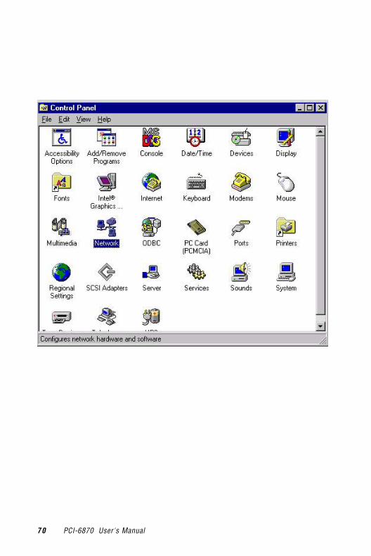
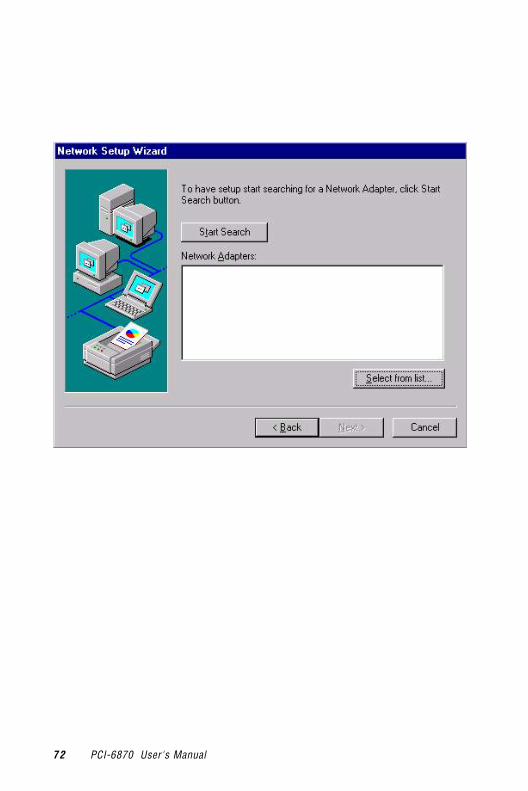
5.2.2 Installation for Windows NTInsert the disk, or otherwise make the files available to the system,and run the appropriate executable. Then proceed as directed by theprompts.
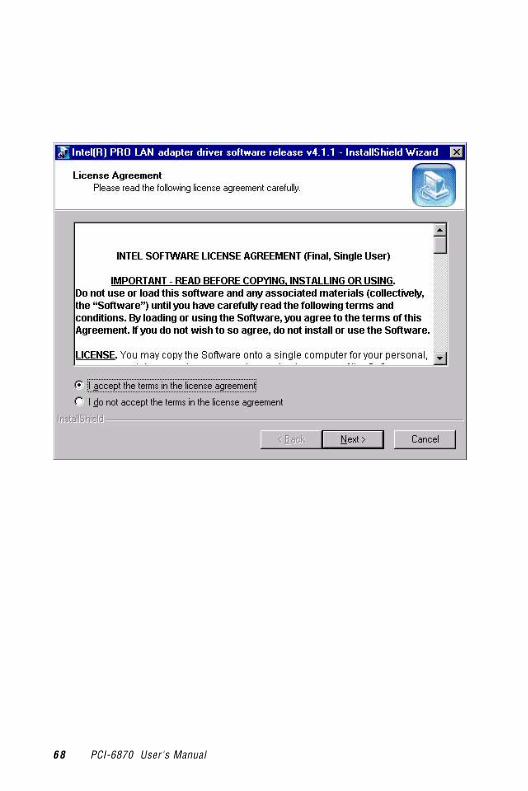
68 PCI-6870 User's Manual

Chapter 5 PCI Bus Ethernet Interface 69
70 PCI-6870 User's Manual

Chapter 5 PCI Bus Ethernet Interface 71
72 PCI-6870 User's Manual

Chapter 5 PCI Bus Ethernet Interface 73

74 PCI-6870 User's Manual

Chapter 5 PCI Bus Ethernet Interface 75

76 PCI-6870 User's Manual

Chapter 5 PCI Bus Ethernet Interface 77

78 PCI-6870 User's Manual

Chapter 5 PCI Bus Ethernet Interface 79

80 PCI-6870 User's Manual

Chapter 5 PCI Bus Ethernet Interface 81

82 PCI-6870 User's Manual
5.3 Further informationIntel website:http://www.intel.com/design/network/products/lan/controllers/82562.htm
Advantech website: www.advantech.comwww.advantech.com.tw

Audio
• Introduction
• Installation of audio driver forWindows 98 and 2000
• Installation of audio driver forWindows NT
6CHAPTER

84 PCI-6870 User's Manual
6.1 IntroductionThe PCI-6870's on-board audio interface provides high-quality stereosound and FM music synthesis (ESFM) by using the Cs5530A audiocontroller from Cyrix Corporation. The audio interface can record,compress, and play back voice, sound, and music with a built-in mixercontrol. The PCI-6870's on-board audio interface also supports thePlug and Play (PnP) standard and provides PnP configuration foraudio, FM, and MPU-104 logical devices. It is compatible with AC97version 2.0, voice, and music functions. The ESFM synthesizer isregister compatible with the OPL3 and has extended capabilities.
6.2 Installation of audio driverBefore installing the audio driver, please take note of the proceduresdetailed below. You must know which operating system you are usingin your PCI-6870's, and then refer to the corresponding installationflow chart. Just follow the steps in the flow chart. You can quicklyand successfully complete the installation, even though you are notfamiliar with instructions for Windows.
Note: The CD-ROM drive is designated as "D" throughoutthis chapter.

Chapter 6 Audio 85
6.2.1 Installation for Windows 98 and 2000

86 PCI-6870 User's Manual

Chapter 6 Audio 87

88 PCI-6870 User's Manual

Chapter 6 Audio 89
90 PCI-6870 User's Manual

Chapter 6 Audio 91

92 PCI-6870 User's Manual
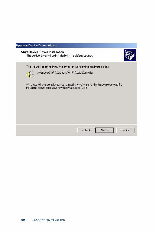
6.2.2 Installation for Windows NT

Chapter 6 Audio 93

94 PCI-6870 User's Manual

Programmingthe WatchdogTimerThe PCI-6870 is equipped with awatchdog timer that resets theCPU or generates an interrupt ifprocessing comes to a standstillfor any reason. This featureensures system reliability inindustrial standalone or unmannedenvironments.
AAPPENDIX

96 PCI-6870 User's Manual
A.1 Programming the Watchdog TimerTo program the watchdog timer, you must write a program whichwrites I/O port address 443 (hex). The output data is a value of timeinterval. The value range is from 01 (hex) to 3E (hex), and the relatedtime interval is 1 sec. to 62 sec.
Data Time Interval
01 1 sec.
02 2 sec.
03 3 sec.
04 4 sec.
• •
• •
• •
3E 62 sec.

Appendix A Programming the Watchdog Timer 97
After data entry, your program must refresh the watchdog timer byrewriting the I/O port 443 (hex) while simultaneously setting it. Whenyou want to disable the watchdog timer, your program should read I/Oport 443 (hex).
The following example shows how you might program the watchdogtimer in BASIC:10 REM Watchdog timer example program20 OUT &H443, data REM Start and restart the watchdog30 GOSUB 1000 REM Your application task #1,40 OUT &H443, data REM Reset the timer50 GOSUB 2000 REM Your application task #2,60 OUT &H443, data REM Reset the timer70 X=INP (&H443) REM, Disable the watchdog timer80 END
1000 REM Subroutine #1, your application task• •• •• •1070 RETURN2000 REM Subroutine #2, your application task• •• •• •2090 RETURN

98 PCI-6870 User's Manual

BFillerThis appendix is supplied so that we canuse the old Appendixes C and D, whichare perfectly good, without changing allthe references to them that appear in thetext. We didn't want anyone to think thatwe forgot Appendix B.
APPE
ND
IX

100 PCI-6870 User's Manual
This page intentionally left pretty much blank.

Appendix C Pin Assignments 101
Pin AssignmentsThis appendix contains information of a detailedor specialized nature. It includes:
• CRT display connector
• RS-232/422/485 serial port connector
• Keyboard and mouse connector
• External keyboard connector
• Main power connectors (AT/ATX)
• IDE connector
• RS-232 serial port connector
• Ethernet RJ-45 connector
• Floppy connector
• Parallel connector
• IR connector
• HDD LED connector
• CompactFlash card connector
CAPPENDIX

102 PCI-6870 Series Appendix C
C.1 CompactFlash Card Connector (SK1)
Table C-1: CompactFlash card connector
Pin Signal Pin Signal1 GND 2 D033 D04 4 D055 D06 6 D077 * CS0 8 A102
9 * ATA SEL 10 A092
11 A082 12 A072
13 +5 V 14 A062
15 A052 16 A042
17 A032 18 A0219 A01 20 A0021 D00 22 D0123 D02 24 * IOCS1625 * CD2 26 * CD127 D111 28 D121
29 D131 30 D141
31 D151 32 * CS11
33 * VS1 34 * IORD35 * IOWR 36 * WE3
37 INTRQ 38 +5 V39 * CSEL 40 * VS241 * RESER 42 IORDY43 * INPACK 44 * REG3
45 * DASP 46 * PDIAG47 D081 48 D091
49 D10 50 GND* low active

Appendix C Pin Assignments 103
C.2 IR Connector (CN1)
Table C-2: IR connector
Pin Signal1 +5 V2 IRRX3 IR_RX4 GND5 IR_TX
1 2 3

104 PCI-6870 Series Appendix C
C.3 VGA Display Connector (CN2)
Table C-3: CRT display connector
Pin Signal Pin Signal1 RED 9 N/C2 GREEN 10 GND3 BLUE 11 N/C4 N/C 12 N/C5 GND 13 H-SYNC6 GND 14 V-SYNC7 GND 15 N/C8 GND
1511
106
51
10 15
16
11
5

Appendix C Pin Assignments 105
C.4 COM1 RS-232 Serial Port (CN3)
Table C-4: COM1 RS-232 serial port
Pin Signal1 DCD2 SIN3 SOUT4 DTR5 GND6 DSR7 RTS8 CTS9 RI
54321
9876

106 PCI-6870 Series Appendix C
C.5 Keyboard and Mouse Connnector (CN4)
Table C-5: Keyboard and mouse connectorPin Signal
1 KBCLK2 KBDATA3 MSCLK signal4 GND5 +5V6 MSDATA signal
5
3
12
4
6

Appendix C Pin Assignments 107
C.6 ATX Power Connector (CN6)
Table C-6: ATX power connector
Pin Signal1 5 V SB2 GND3 PS_ON
1 2 3

108 PCI-6870 Series Appendix C
C.7 Printer Port Connector (CN7)
Table C-7: Parallel port connector
Pin Signal1 * STROBE2 * AUTOFD3 D04 ERR5 D16 * INIT7 D28 * SLCTINI9 D310 GND11 D412 GND13 D514 GND15 D616 GND17 D718 GND19 ACK#20 GND21 BUSY22 GND23 PE24 GND25 SLCT26 GND
* low active
25 23 3 1
26 24 4 2

Appendix C Pin Assignments 109
C.8 COM2 RS-422/485 Serial Port (CN8)
Table C-8: COM2 RS-232/422/485 serial port
Pin RS-422 port RS-485 port1 TXD- DATA-2 N/C N/C3 TXD+ DATA+4 N/C N/C5 RXD+ N/C6 N/C N/C7 RXD- N/C8 N/C N/C9 GND GND10 N/C N/C
10
2
9
1

C.9 USB1/USB2 Connector (CN9)
Table C-9: USB1/USB2 connector
USB1 USB21 USBV0 2 USBV13 USBD0- 4 USBD1-5 USBDO+ 6 USBD1+7 USBG0 8 USBG19 Chassis GND 10 N/C
1
9
2
10

C.10 EBX Power Connector (CN11)

112 PCI-6870 Series Appendix C
C.11 CPU Fan Power Connector (CN12)
Table C-10: CPU fan power connector
Pin Signal1 GND2 +12 V3 FAN_DEC
1 2 3

Appendix C Pin Assignments 113
C.12 ATX Power Switch (CN13)
Table C-11:ATX power switch
Pin Signal1 Standby 5 V2 Power ON
1

114 PCI-6870 Series Appendix C
C.13 CD-ROM in connector (CN14)
Table C-12: CD-ROM connector
Pin Signal
1 CD_R
2 GND
3 GND
4 CD_L

Appendix C Pin Assignments 115
C.14 IDE Hard Drive Connector (CN15)
Table C-13: IDE hard drive connector
Pin Signal Pin Signal1 IDE RESET* 2 GND3 DATA 7 4 DATA 85 DATA 6 6 DATA 97 DATA 5 8 DATA 109 DATA 4 10 DATA 1111 DATA 3 12 DATA 1213 DATA 2 14 DATA 1315 DATA 1 16 DATA 1417 DATA 0 18 DATA 1519 GND 20 N/C21 DRQ 22 GND23 IO WRITE 24 GND25 IO READ 26 GND27 IO CHANNEL READY 28 Cable Select29 HDACKO* 30 GND31 IRQ14 32 N/C33 ADDR 1 34 Reserved35 ADDR 0 36 ADDR 237 CS1# 38 CS3#39 IDE ACTIVE* 40 GND41 5 V 42 5 V43 GND 44 NC
* low active

116 PCI-6870 Series Appendix C
C.15 Audio connector (CN17)
Table C-14: Audio connector (CN12)
Pin Signal Pin Signal
1 SPEAKER OUT R+ 2 SPEAKER OUT R-
3 SPEAKER OUT L+ 4 SPEAKER OUT L-
5 LINE OUT R 6 LINE OUT L
7 GND 8 GND
9 LINE IN R 10 LINE IN L
11 GND 12 GND
13 MIC1 14 NC
15 MIC2 16 GND
414
15 3
16
13 1
2
C.16 Secondary IDE (ATA33)
C.17 Video Expansion Connector (CN19)

Appendix C Pin Assignments 117
C.18 Floppy Drive Connector (CN20)
Table C-15: Floppy drive connector
Pin Signal Pin Signal1 GND 2 RWC#3 GND 4 N/C5 GND 6 DS17 GND 8 INDEX#9 GND 10 MOA#11 GND 12 DSB#13 GND 14 DSA#15 GND 16 MOB#17 GND 18 DIR#19 GND 20 STEP#21 GND 22 WD#23 GND 24 WE#25 GND 26 TRAK0#27 GND 28 WP#29 GND 30 RDATA#31 GND 32 HEAD#33 GND 34 DSKCHG#
* low active
33 31 .... 3 1
34 32 .... 4 2

118 PCI-6870 Series Appendix C

DSystemAssignmentsThis appendix contains information of adetailed or specialized nature. It includes:
• System I/O ports
• DMA channel assignments
• Interrupt assignments
• 1st MB memory mapAP
PEN
DIX

120 PCI-6870 User's Manual
D.1 System I/O Ports
Table D-1: System I/O ports
Addr. range (Hex) Device000-01F DMA controller020-021 Interrupt controller 1, master022-023 Chipset address040-05F 8254 timer060-06F 8042 (keyboard controller)070-07F Real-time clock, non-maskable interrupt (NMI)
mask080-09F DMA page register0A0-0BF Interrupt controller 20C0-0DF DMA controller0F0 Clear math co-processor0F1 Reset math co-processor0F8-0FF Math co-processor1F0-1F8 Fixed disk200-207 Game I/O278-27F Parallel printer port 2 (LPT 3)2F8-2FF Serial port 2300-31F Prototype card360-36F Reserved378-37F Parallel printer port 1 (LPT 2)380-38F SDLC, bisynchronous 23A0-3AF Bisynchronous 13B0-3BF Monochrome display and printer adapter (LPT1)3C0-3CF Reserved3D0-3DF Color/graphics monitor adapter3F0-3F7 Diskette controller3F8-3FF Serial port 1* PNP audio I/O map range from 220 ~ 250H (16 bytes) MPU-401 select from 300 ~ 330H (2 bytes)

Appendix D System Assignments 121
D.2 DMA Channel Assignments
Table D-2: DMA channel assignments
Channel Function0 Available1 Available2 Floppy disk (8-bit transfer)3 Available4 Cascade for DMA controller 15 Available6 Available7 Available* Audio DMA select 0, 1 or 3
D.3 Interrupt Assignments
Table D-3: Interrupt assignments
Interrupt# Interrupt sourceIRQ 0 Interval timerIRQ 1 KeyboardIRQ 2 Interrupt from controller 2 (cascade)IRQ 8 Real-time clockIRQ 9 Cascaded to INT 0A (IRQ 2)IRQ 10 AvailableIRQ 11 Watchdog TimerIRQ 12 PS/2 mouse (non-releasable)IRQ 13 INT from co-processorIRQ 14 Fixed disk controller (primary)IRQ 15 Fixed disk controller (secondary)IRQ 3 Serial communication port 2IRQ 4 Serial communication port 1IRQ 5 Parallel port 2IRQ 6 Diskette controller (FDC)IRQ 7 Parallel port 1 (print port)* PNP audio IRQ select: 5, 7, 9 or 10* Ethernet function is auto-sensing
122 PCI-6870 User's Manual
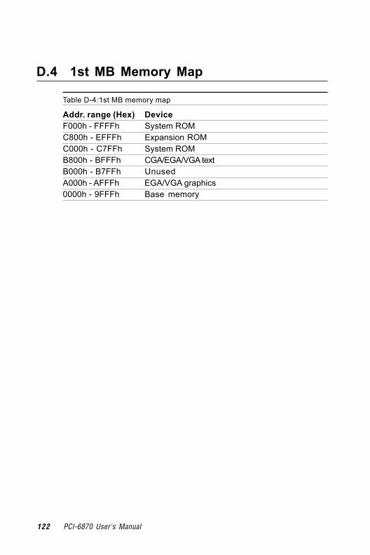
D.4 1st MB Memory Map
Table D-4:1st MB memory map
Addr. range (Hex) DeviceF000h - FFFFh System ROMC800h - EFFFh Expansion ROMC000h - C7FFh System ROMB800h - BFFFh CGA/EGA/VGA textB000h - B7FFh UnusedA000h - AFFFh EGA/VGA graphics0000h - 9FFFh Base memory