
PCA-6003 - Advantech
112
PCA-6003 Full-sized socket 370 Intel ® Pentium ® III processor- based PCI/ISA-bus CPU card
Transcript of PCA-6003 - Advantech
PCA-6003Full-sized socket 370 Intel®Pentium® III processor-based PCI/ISA-bus CPUcard

Copyright noticeThis document is copyrighted, 2000, by Advantech Co., Ltd. All rightsare reserved. Advantech Co., Ltd. reserves the right to make improve-ments to the products described in this manual at any time withoutnotice.
No part of this manual may be reproduced, copied, translated ortransmitted in any form or by any means without the prior writtenpermission of Advantech Co., Ltd. Information provided in this manualis intended to be accurate and reliable. However, Advantech Co., Ltd.assumes no responsibility for its use, nor for any infringements uponthe rights of third parties which may result from its use.
Acknowledgements• AWARD is a trademark of AWARD Software, Inc.
• Intel® and Pentium® III are trademarks of Intel Corporation.
• MS-DOS is a trademark of Microsoft Corporation.
• WinBond is a trademark of Winbond Corporation.
• VIA is a registered trademark of VIA Technologies Inc.
All other product names or trademarks are the properties of theirrespective owners.
Part No. 2002600301
2nd Edition Printed in Taiwan Feb. 2002

A Message to the Customer
Advantech customer servicesEach and every Advantech product is built to the most exactingspecifications to ensure reliable performance in the harsh anddemanding conditions typical of industrial environments. Whetheryour new Advantech equipment is destined for the laboratory or thefactory floor, you can be assured that your product will provide thereliability and ease of operation for which the name Advantech hascome to be known.
Your satisfaction is our primary concern. Here is a guide toAdvantech’s customer services. To ensure you get the full benefit ofour services, please follow the instructions below carefully.
Technical supportWe want you to get the maximum performance from your products. Soif you run into technical difficulties, we are here to help. For the mostfrequently asked questions, you can easily find answers in yourproduct documentation. These answers are normally a lot moredetailed than the ones we can give over the phone.
So please consult this manual first. If you still cannot find the answer,gather all the information or questions that apply to your problem, andwith the product close at hand, call your dealer. Our dealers are welltrained and ready to give you the support you need to get the mostfrom your Advantech products. In fact, most problems reported areminor and are able to be easily solved over the phone.
In addition, free technical support is available from Advantechengineers every business day. We are always ready to give advice onapplication requirements or specific information on the installation andoperation of any of our products.

elbatnosirapmocseireS3006-ACP
ledoM 1A00-V3006-ACP 1A00-EV3006-ACP 1A00-H3006-ACP
:UPC letnI ® muitneP ® 073tekcoSIII � � �
:tespihcmetsyS T331ELPollopAAIV � � �
:SOIB SOIBhsalFP&PdrawA � � �
:ehcaC2L UPCnoBK215/652/821 � � �
:MARmetsyS.xaM)stekcosnip-861X2(BG1
� � �
troPBSU 2 2 2srotcennocEDIE2 � � �
stroplellarap1,laires2 � � �
:AGV AGV/PGA)ni-tliubtespihC(
� � �
:NAL tenrehtET-esaB001/01)C9318ketlaeR:tespihc(
✕ � �
)evirdhgihASI(ASiH ✕ ✕ �

Product warrantyAdvantech warrants to you, the original purchaser, that each of itsproducts will be free from defects in materials and workmanship for twoyears from the date of purchase.
This warranty does not apply to any products which have beenrepaired or altered by persons other than repair personnel authorizedby Advantech, or which have been subject to misuse, abuse, accidentor improper installation. Advantech assumes no liability under theterms of this warranty as a consequence of such events.
If an Advantech product is defective, it will be repaired or replaced atno charge during the warranty period. For out-of-warranty repairs, youwill be billed according to the cost of replacement materials, servicetime and freight. Please consult your dealer for more details.
If you think you have a defective product, follow these steps:
1. Collect all the information about the problem encountered. (Forexample, type of PC, CPU speed, Advantech products used, otherhardware and software used, etc.) Note anything abnormal and listany on-screen messages you get when the problem occurs.
2. Call your dealer and describe the problem. Please have yourmanual, product, and any helpful information readily available.
3. If your product is diagnosed as defective, obtain an RMA (returnmaterial authorization) number from your dealer. This allows us toprocess your return more quickly.
4. Carefully pack the defective product, a fully-completed Repair andReplacement Order Card and a photocopy proof of purchase date(such as your sales receipt) in a shippable container. A productreturned without proof of the purchase date is not eligible forwarranty service.
5. Write the RMA number visibly on the outside of the package andship it prepaid to your dealer.

Initial InspectionBefore you begin installing your card, please make sure that thefollowing materials have been shipped:
• 1 PCA-6003 socket 370 Pentium III® processor-based single boardcomputer
• 1 Pentium III® processor (optional)
• 1 PCA-6003 startup Manual
• 1 CD driver utility and manual (in PDF format)
• 1 FDD cable, P/N: 1701340703
• 2 UDMA 66/100 HDD cables, P/N: 1701400452
• 1 printer (parallel port) cable & COM port cable kit, P/N: 1700060305
• 1 ivory cable for PS/2 keyboard and PS/2 mouse, P/N: 1700060202
• 1 USB cable (optional), P/N 1700100170
If any of these items are missing or damaged, contact your distributoror sales representative immediately.
We have carefully inspected the PCA-6003 mechanically andelectrically before shipment. It should be free of marks and scratchesand in perfect working order upon receipt.
As you unpack the PCA-6003, check it for signs of shipping damage.(For example, damaged box, scratches, dents, etc.) If it is damaged or itfails to meet the specifications, notify our service department or yourlocal sales representative immediately. Also notify the carrier. Retainthe shipping carton and packing material for inspection by the carrier.After inspection, we will make arrangements to repair or replace theunit.

Content
Chapter 1 Hardware Configuration ............................... 11.1 Introduction .......................................................................... 21.2 Features ................................................................................. 31.3 Specifications ........................................................................ 5
1.3.1 System .........................................................................51.3.2 Memory .......................................................................51.3.3 Input/Output ................................................................61.3.4 VGA interface .............................................................61.3.5 Ethernet LAN .............................................................61.3.7 Industrial features ........................................................ 61.3.8 Mechanical and environmental specifications .............7
1.4 Board Layout: Main Features ........................................... 81.5 Jumpers and Connectors .................................................... 91.6 Board Layout: Jumper and Connector Locations ........ 111.7 Safety Precautions .............................................................. 121.8 Jumper Settings ................................................................. 13
1.8.1 How to set jumpers ................................................... 131.8.2 CMOS clear (J1) ....................................................... 141.8.3 Watchdog timer output (J2) ...................................... 14
1.9 System Memory ................................................................. 151.9.1 Sample calculation: DIMM memory capacity ........... 151.9.2 Supplementary information about DIMMs ................ 16
1.10 Memory Installation Procedures .................................. 161.11 Cache Memory ................................................................. 161.12 CPU Installation ............................................................... 17
Chapter 2 Connecting Peripherals ............................. 192.1 Primary (CN1) and Secondary (CN2) IDE Connectors 202.2 Floppy Drive Connector (CN3) ....................................... 212.3 Parallel Port (CN4) ............................................................ 212.4 USB Port (CN6) ................................................................. 22

2.5 VGA Connector (CN7) ...................................................... 222.6 10/100Base-T Ethernet Connector (CN8) .................... 232.7 Serial Ports (CN9: COM1; CN10: COM2) ................... 232.8 PS/2 Keyboard and Mouse Connector (CN11) ............. 242.9 External Keyboard Connector (CN12) .......................... 242.10 Infrared (IR) Connector (CN13) ................................... 252.11 CPU Fan Connector (CN14) .......................................... 252.12 Front Panel Connectors (CN16, CN17, CN18, CN19,CN21 and CN29) ...................................................................... 26
2.12.1 Keyboard lock and power LED (CN16) ................. 262.12.2 External speaker (CN17) ........................................ 262.12.3 Reset (CN18) .......................................................... 272.12.4 HDD LED (CN19) ................................................. 272.12.5 SM Bus Connector (CN29) ..................................... 272.12.6 Connecting to SNMP-1000 remote manager .......... 27
2.13 ATX Power Control Connectors (CN20 and CN21) .. 282.13.1 ATX feature connector (CN20) and soft powerswitch connector (CN21) ................................................... 282.13.2 Controlling the soft power switch ............................ 29
2.14 LCD Connector (CN41) ................................................. 292.15 LCD Inverter Power Connector (CN42) ..................... 292.16 AC-97 Audio Interface (CN43) ..................................... 29
Chapter 3 Award BIOS Setup ...................................... 313.1 Introduction ........................................................................ 323.2 Entering Setup .................................................................... 323.3 Standard CMOS Setup ...................................................... 33
3.3.1 CMOS RAM backup ................................................ 333.4 Advanced BIOS Features ................................................. 34
3.4.1 Virus Warning ............................................................ 343.4.2 CPU Internal Cache / External Cache ...................... 343.4.3 CPU L2 Cache ECC Checking ................................ 353.4.4 First/Second/Third/Other Boot Device ...................... 353.4.5 Swap Floppy Drive .................................................... 353.4.6 Boot UP Floppy Seek ................................................ 353.4.7 Boot Up NumLock Status ......................................... 35

3.4.8 Gate A20 Option ....................................................... 353.4.9 Typematic Rate Setting ............................................. 353.4.10 Typematic Rate (Chars/Sec) ................................... 363.4.11 Typematic Delay (msec) ......................................... 363.4.12 Security Option ........................................................ 363.4.13 OS Select for DRAM 64MB .................................. 363.4.14 Video BIOS Shadow ............................................... 363.4.15 Small Logo (EPA)Show .......................................... 36
3.5 Advanced Chipset Features ............................................. 373.5.1 DRAM Clock ............................................................ 373.5.2 SDRAM Cycle Length .............................................. 373.5.3 Bank Interleave ......................................................... 383.5.4 Memory Hole ............................................................ 383.5.5 P2C/P2P Concurrency .............................................. 383.5.6 System BIOS Cacheable........................................... 383.5.7 AGP Aperture Size ................................................... 383.5.8 Onchip USB .............................................................. 383.5.9 USB Keyboard Support ............................................ 393.5.10 USB Mouse Support ............................................... 393.5.11 CPU to PCI Write Buffer ........................................ 393.5.12 PCI Dynamic Bursting ............................................ 393.5.13 PCI Master 0 WS Write .......................................... 393.5.14 PCI Delay Transaction ........................................... 393.5.15 PCI#2 Access #1 Retry ......................................... 393.5.16 AGP Master 1 WS Write ........................................ 403.5.17 Memory Parity/ ECC Check ................................... 40
3.6 Integrated Peripherals ...................................................... 403.6.1 On-Chip Primary/Secondary PCI IDE...................... 403.6.2 IDE Primary Master/Slave PIO/UDMA Mode, IDESecondary Master/Slave PIO/UDMA Mode (Auto) ......... 403.6.3 Init Display First ........................................................ 413.6.4 IDE HDD Block Mode ............................................. 413.6.5 Onboard FDD Controller ........................................... 413.6.6 Onboard Serial Port 1 (3F8H/IRQ4) ......................... 413.6.7 Onboard Serial Port 2 (2F8H/IRQ3) ......................... 41
3.6.8 UART 2 Mode Select ............................................... 413.6.9 Onboard Parallel Port (378H/IRQ7) ......................... 413.6.10 Onboard Parallel Port Mode (ECP + EPP) ............ 423.6.11 ECP Mode Use DMA ............................................. 423.6.12 EPP Mode Select .................................................... 42
3.7 Power Management Setup ............................................... 433.7.1 ACPI function ........................................................... 433.7.2 Power Management .................................................. 433.7.3 PM Control by APM ................................................. 443.7.4 Video Off Option ....................................................... 443.7.5 Video Off Method ..................................................... 443.7.6 MODEM Use IRQ ................................................... 453.7.7 Soft-Off by PWRBTN .............................................. 453.7.8 State After Power Failure ......................................... 45
3.8 Wake Up Event .................................................................. 463.8.1 VGA .......................................................................... 463.8.2 LPT & COM............................................................. 463.8.3 HDD & FDD ............................................................ 463.8.4 Power On by LAN.................................................... 463.8.5 Power On by Modem ................................................ 473.8.6 Power On by Alarm .................................................. 47
3.9 PnP/PCI Configurations .................................................... 483.9.1 PnP OS Installed ....................................................... 483.9.2 Reset Configuration Data .......................................... 483.9.3 Resources controlled by: ........................................... 48
3.10 PC Health Status .............................................................. 493.10.1 Current CPU Temperature ...................................... 493.10.2 Current CPUFAN Speed ........................................ 493.10.5 VCORE ................................................................... 493.10.7 +2.5/ +3.3V/ + 5V/ +12V ........................................ 49
3.11 Load Setup Defaults ........................................................ 503.12 Password Setting .............................................................. 503.13 Save & Exit Setup ........................................................... 513.14 Exit Without Saving ......................................................... 51

Chapter 4 AGP SVGA Setup ........................................ 534.1 Before You Begin ............................................................... 544.2 Features ............................................................................... 544.3 Installation .......................................................................... 55
Chapter 5 LAN Configuration ...................................... 575.1 Introduction ........................................................................ 585.2 Features ............................................................................... 585.3 Driver Installation .............................................................. 595.4 Windows 9X Drivers Setup Procedure ........................... 605.5 Windows NT Drivers Setup Procedure .......................... 665.6 Windows 2000 Drivers Setup Procedure ....................... 71
Appendix A Programming the Watchdog Timer ........ 79A.1 Programming the Watchdog Timer ................................ 80
Appendix B Pin Assignments ..................................... 83B.1 IDE Hard Drive Connector (CN1, CN2) ....................... 84B.2 Floppy Drive Connector (CN3) ...................................... 85B.3 Parallel Port Connector (CN4) ........................................ 86B.4 USB Connector (CN6) ..................................................... 87B.5 VGA Connector (CN7) ..................................................... 87B.6 Keyboard and Mouse Connnector (CN11) ................... 88B.7 External Keyboard Connector (CN12) .......................... 88B.8 IR Connector (CN13) ....................................................... 89B.9 CPU Fan Power Connector (CN14) ............................... 89B.10 Power LED and Keylock Connector (CN16) ............. 90B.11 External Speaker Connector (CN17) .......................... 90B.12 Reset Connector (CN18) ............................................... 91B.13 HDD LED Connector (CN19) ...................................... 91B.14 ATX Feature Connector (CN20) .................................. 91B.15 ATX Soft Power Switch (CN21) .................................... 92B.16 SM Bus Connector (CN29) ........................................... 92B.17 18-bit LCD Display Connector (CN41) ....................... 93B.18 Flat panel inverter power connector (CN42) ............. 94B.19 AC-97 Audio Interface (CN43) ..................................... 94

B.20 System I/O Ports ............................................................. 95B.21 DMA Channel Assignments ......................................... 96B.22 Interrupt Assignments ................................................... 96B.23 1st MB Memory Map .................................................... 97B.24 PCI Bus Map ................................................................... 97
TableTable 1-1: Jumpers ........................................................................................................ 9Table 1-2: Connectors .................................................................................................. 10Table 1-3: CMOS clear (J1) ......................................................................................... 14Table 1-4: Watchdog timer output (J2) ........................................................................ 14Table 1-5: DIMM module allocation table .................................................................. 15Table 1-6: DIMM memory capacity sample calculation ............................................ 15Table 2-1: Serial port connections (COM1, COM2) .................................................. 23Table 2-2: PS/2 or ATX power supply LED status .................................................... 26Table B-1: IDE hard drive connector (CN1, CN2) ...................................................... 84Table B-2: Floppy drive connector (CN3) .................................................................. 85Table B-3: Parallel port connector (CN4) .................................................................... 86Table B-4: USB1/USB2 connector (CN6) ................................................................... 87Table B-5: VGA connector (CN7) ............................................................................... 87Table B-6: Keyboard and mouse connector (CN11) ................................................... 88Table B-7: External keyboard connector (CN12) ........................................................ 88Table B-8: IR connector (CN13) ................................................................................. 89Table B-9: CPU fan power connector (CN14) ............................................................ 89Table B-10: Power LED and keylock connector (CN16) ............................................ 90Table B-11: External speaker (CN17) .......................................................................... 90Table B-12: Reset connector (CN18) .......................................................................... 91Table B-13: HDD LED connector (CN19) .................................................................. 91Table B-14: ATX feature connector (CN20) ............................................................... 91Table B-15: ATX soft power switch (CN21) ............................................................. 92Table B-16: SM Bus Connector (CN29) ..................................................................... 92Table B-17: 18-bit LCD display connector ................................................................. 93Table B-18 ................................................................................................................... 94Table B-19 ................................................................................................................... 94Table B-20: System I/O ports ..................................................................................... 95Table B-21: DMA channel assignments ...................................................................... 96Table B-22: Interrupt assignments .............................................................................. 96Table B-23: 1st MB memory map .............................................................................. 97Table B-24: PCI bus map ............................................................................................ 97

FigureFigure 1-1: Board layout: main features ........................................................................ 8Figure 1-2: Board layout: jumper and connecter locations .......................................... 11Figure 3-1: Award BIOS Setup initial screen ............................................................... 32Figure 3-2: Standard CMOS features screen ............................................................... 33Figure 3-3: Advanced BIOS features screen ................................................................ 34Figure 3-4: Advanced chipset features screen ............................................................. 37Figure 3-5: Integrated peripherals ................................................................................ 40Figure 3-6: Power management setup screen ............................................................... 43Figure 3-7: Wake-up event screen ................................................................................ 46Figure 3-8: PnP/PCI configurations screen .................................................................. 48Figure 3-9: PC health status screen ............................................................................. 49


Hardware Configuration
This chapter gives background informa-tion on the PCA-6003. It then shows youhow to configure the card to match yourapplication and prepare it for installationinto your PC.
Sections include:
• Introduction
• Features
• Specifications
• Board Layout
• Jumpers and Connectors
• Safety Precautions
• Jumper Settings
• System Memory
• Memory Installation Procedures
• Cache Memory
• CPU Installation
1CHAPTER

2 PCA-6003 User's Manual
1.1 IntroductionThe PCA-6003 Series all-in-one industrial grade single board computeris a low cost yet full-featured product. It uses VIA's Apollo PLE133chipset with integrated VGA and supports Intel Pentiun III / Celeronprocessor up to 1.26GHz and above. Its on-board I/O functions andindustrial features can meet most of the requirements of industrialapplications.
The CPU provides 128/256/512 KB on-CPU L2 cache, eliminating theneed for external SRAM chips. It has two PCI EIDE interfaces (for upto four devices) and a floppy disk drive interface (for up to twodevices). Other features include two RS-232 serial ports (16C550UARTs with 16-byte FIFO or compatible), one enhanced parallel port(supports EPP/ECP) and two USB (Universal Serial Bus) ports. ThePCI enhanced IDE controller supports Ultra DMA/33/66/100 and PIOMode 4 operation. This provides data transfer rates of 33/66/100 MB/sec. System BIOS supports boot-up from an IDE CD-ROM, SCSICD-ROM, LS-120, IDE HDD, SCSI HDD, ZIP-100, LAN, and FDD.
A backup of CMOS data is stored in the Flash memory, which protectsdata even after a battery failure. Also included is a 63-level watchdogtimer, which resets the CPU or generates an interrupt if a programcannot be executed normally. This enables reliable operation inunattended environments.
The PCA-6003 Series offers several impressive industrial features suchas chipset built-in VGA (AGP) interface, a 10/100Base-T networkingcontroller, two DIMM slots for a total of 1 GB RAM memory, and ahigh driving ISA bus. The AC-97 audio interface (requires an audioextension card: P/N PCA-AUDIO-00A1) provides audio input andoutput. All these make it an ideal choice for applications that requireboth high performance and full functionality.
The remote management interface enables the PCA-6003 to bemanaged through Ethernet when it is connected to the SNMP-1000Remote HTTP/SNMP System Manager.

Chapter 1 Hardware Configuration 3
1.2 Features1. Fan status monitoring and alarm: To prevent system overheating
and damage, the CPU fan can be monitored for speed and failure.The fan is set for its normal RPM range and alarm thresholds.
2. Temperature monitoring and alarm: To prevent system overheat-ing and damage, the CPU card supports processor thermal sensingand auto-protection.
3. Voltage monitoring and alarm: System voltage levels are moni-tored to ensure stable current flows to critical components. Voltagespecifications will become even more critical for processors of thefuture. Thus monitoring will become ever more necessary to ensureproper system configuration and management.
4. ATX soft power switch: Through the BIOS, the power button canbe defined as the "Standby" (aka "Suspend" or "Sleep") button oras the "Soft-Off" button (see Section 3.6.6 Soft-off by PWR-BTN).Regardless of the setting, pushing the power button for more than4 seconds will enter the Soft-Off mode.
5. Power-on by modem (requires modem): This allows a computer tobe turned on remotely through an internal or external modem. Userscan thus access information on their computers from anywhere inthe world.
6. Power-on by LAN: This allows you to remotely power up yoursystem through your network by sending a wake-up frame orsignal. With this feature, you can remotely upload/ download datato/from systems during off-peak hours.
7. Message LED: Chassis LEDs now act as information providers.The way a particular LED illuminates indicates the stage thecomputer is in. A single glimpse provides useful information to theuser.
Note: Some of the features mentioned above are notavailable with all models. For more information aboutthe specifications of a particular model, see Section1.3: Specifications.

4 PCA-6003 User's Manual
8. More:• Additional metal bracket for CPU stabilization• Power On by Alarm: Powers up your computer at a certain
time• Virus warning: During and after system boot-up, any attempt
to write to the boot sector or partition table of the hard diskdrive will halt the system. In this case, a warning message willbe displayed. You can then run your anti-virus program tolocate the problem
Chapter 1 Hardware Configuration 5
1.3 Specifications
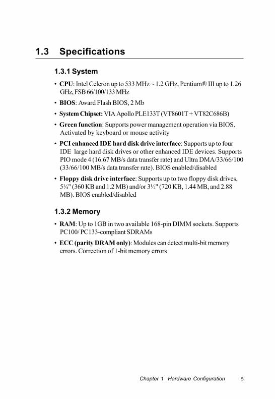
1.3.1 System• CPU: Intel Celeron up to 533 MHz ~ 1.2 GHz, Pentium® III up to 1.26
GHz, FSB 66/100/133 MHz• BIOS: Award Flash BIOS, 2 Mb• System Chipset: VIA Apollo PLE133T (VT8601T + VT82C686B)• Green function: Supports power management operation via BIOS.
Activated by keyboard or mouse activity• PCI enhanced IDE hard disk drive interface: Supports up to four
IDE large hard disk drives or other enhanced IDE devices. SupportsPIO mode 4 (16.67 MB/s data transfer rate) and Ultra DMA/33/66/100(33/66/100 MB/s data transfer rate). BIOS enabled/disabled
• Floppy disk drive interface: Supports up to two floppy disk drives,5¼" (360 KB and 1.2 MB) and/or 3½" (720 KB, 1.44 MB, and 2.88MB). BIOS enabled/disabled
1.3.2 Memory• RAM: Up to 1GB in two available 168-pin DIMM sockets. Supports
PC100/ PC133-compliant SDRAMs• ECC (parity DRAM only): Modules can detect multi-bit memory
errors. Correction of 1-bit memory errors
6 PCA-6003 User's Manual
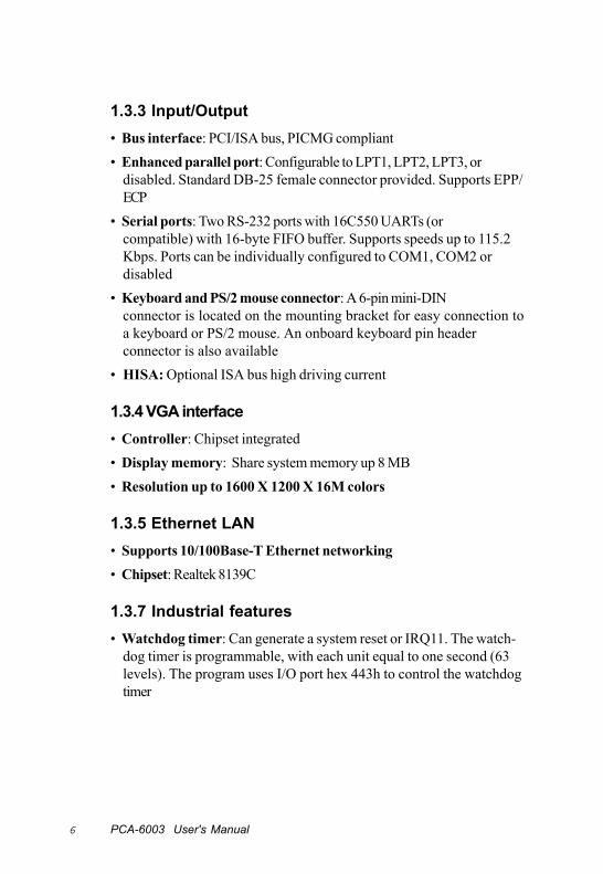
1.3.3 Input/Output• Bus interface: PCI/ISA bus, PICMG compliant• Enhanced parallel port: Configurable to LPT1, LPT2, LPT3, or
disabled. Standard DB-25 female connector provided. Supports EPP/ECP
• Serial ports: Two RS-232 ports with 16C550 UARTs (orcompatible) with 16-byte FIFO buffer. Supports speeds up to 115.2Kbps. Ports can be individually configured to COM1, COM2 ordisabled
• Keyboard and PS/2 mouse connector: A 6-pin mini-DINconnector is located on the mounting bracket for easy connection toa keyboard or PS/2 mouse. An onboard keyboard pin headerconnector is also available
• HISA: Optional ISA bus high driving current
1.3.4 VGA interface• Controller: Chipset integrated• Display memory: Share system memory up 8 MB• Resolution up to 1600 X 1200 X 16M colors
1.3.5 Ethernet LAN• Supports 10/100Base-T Ethernet networking• Chipset: Realtek 8139C
1.3.7 Industrial features• Watchdog timer: Can generate a system reset or IRQ11. The watch-
dog timer is programmable, with each unit equal to one second (63levels). The program uses I/O port hex 443h to control the watchdogtimer

Chapter 1 Hardware Configuration 7
1.3.8 Mechanical and environmental specifications• Operating temperature: 0 ~ 60° C (32 ~ 140° F), depending on CPU• Storage temperature: --20 ~ 70° C (-4 ~ 158° F)• Humidity: 20 ~ 95% non-condensing• Power supply voltage: +5 V, ±12 V• Power consumption:
+5 V @ 6.8 A, +12V @ 400 mA (typical, with Pentium III 1 GHz and256 MB SDRAM)
• Board size: 338 x 122 mm (13.3" x 4.8")• Board weight: 0.5 kg (1.2 lb)

8 PCA-6003 User's Manual
1.4 Board Layout: Main Features
Figure 1-1: Board layout: main features
Two
DIM
M s
ocke
tsup
to 1
GB
SDR
AMEI
DE
Con
nect
ors
Sock
et 3
70Pe
ntiu
m II
I CPU
up to
1.2
6 G
B
FDD
Con
nect
or
CO
M1
Para
llel p
ort
CO
M2
LAN
VGA
PS/2
mou
sean
d ke
yboa
rdco
nnec
tor
RTL
8139
CEt
hern
et c
ontro
ller
Chapter 1 Hardware Configuration 9
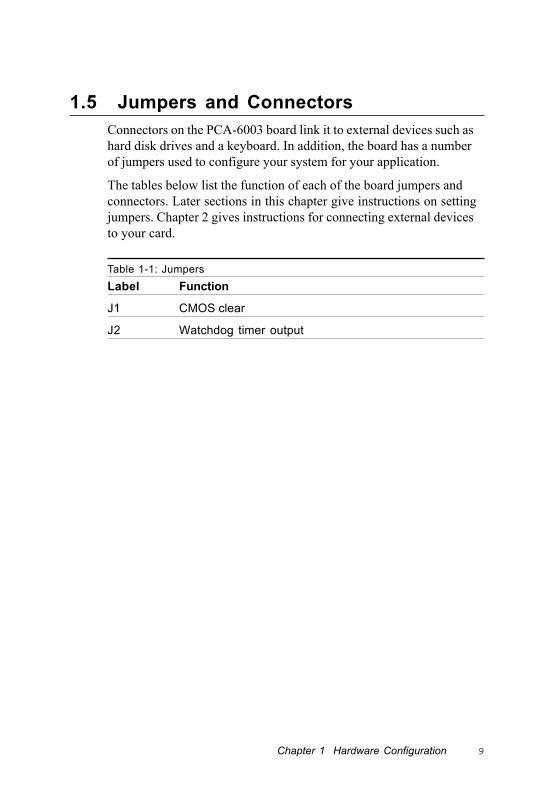
1.5 Jumpers and ConnectorsConnectors on the PCA-6003 board link it to external devices such ashard disk drives and a keyboard. In addition, the board has a numberof jumpers used to configure your system for your application.
The tables below list the function of each of the board jumpers andconnectors. Later sections in this chapter give instructions on settingjumpers. Chapter 2 gives instructions for connecting external devicesto your card.
Table 1-1: JumpersLabel Function
J1 CMOS clear
J2 Watchdog timer output

10 PCA-6003 User's Manual
Table 1-2: ConnectorsLabel Function
CN1 Primary IDE connector
CN2 Secondary IDE connector
CN3 Floppy drive connector
CN4 Parallel port
CN6 USB port
CN7 VGA connector
CN8 10/100Base-T Ethernet connector
CN9 Serial port: COM1
CN10 Serial port: COM2
CN11 PS/2 keyboard and mouse connector
CN12 External keyboard connector
CN13 Infrared (IR) connector
CN14 CPU fan connector
CN16 Keyboard lock and power LED
CN17 External speaker
CN18 Reset connector
CN19 HDD LED connector
CN20 ATX feature connector
CN21 ATX soft power switch
CN29 External SM bus connector
CN41 LCD flat panel connector
CN42 LCD flat panel inverter power connector
CN43 AC-97 Audio Interface
Chapter 1 Hardware Configuration 11
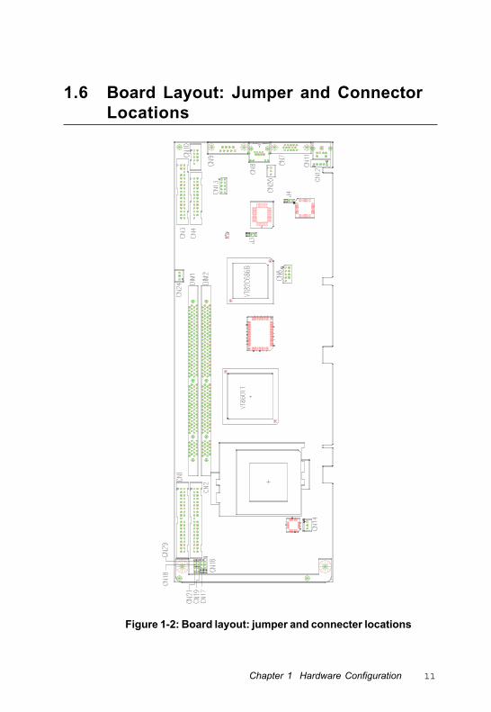
1.6 Board Layout: Jumper and ConnectorLocations
Figure 1-2: Board layout: jumper and connecter locations
12 PCA-6003 User's Manual
1.7 Safety Precautions
Warning! Always completely disconnect the power cord fromyour chassis whenever you work with the hardware.Do not make connections while the power is on.Sensitive electronic components can be damaged bysudden power surges. Only experiencedelectronics personnel should open the PC chassis.
Caution! Always ground yourself to remove any static chargebefore touching the CPU card. Modern electronicdevices are very sensitive to static electric charges.As a safety precaution, use a grounding wrist strapat all times. Place all electronic components in astatic-dissipative surface or static-shielded bag whenthey are not in the chassis.

Chapter 1 Hardware Configuration 13
1.8 Jumper SettingsThis section provides instructions on how to configure your card bysetting jumpers. It also includes the card's default settings and youroptions for each jumper.
1.8.1 How to set jumpersYou configure your card to match the needs of your application bysetting jumpers. A jumper is a metal bridge that closes an electricalcircuit. It consists of two metal pins and a small metal clip (oftenprotected by a plastic cover) that slides over the pins to connect them.To “close” (or turn ON) a jumper, you connect the pins with the clip.To “open” (or turn OFF) a jumper, you remove the clip. Sometimes ajumper consists of a set of three pins, labeled 1, 2, and 3. In this caseyou connect either pins 1 and 2, or 2 and 3.
A pair of needle-nose pliers may be useful when setting jumpers.

14 PCA-6003 User's Manual
1.8.2 CMOS clear (J1)The PCA-6003 CPU card contains a jumper that can erase CMOS dataand reset the system BIOS information. Normally this jumper should beset with pins 1-2 closed. If you want to reset the CMOS data, set J1 to2-3 closed for just a few seconds, and then move the jumper back to 1-2 closed. This procedure will reset the CMOS to its default setting.
Table 1-3: CMOS clear (J1)Function Jumper setting
* Keep CMOS data 1-2 closed
Clear CMOS data 2-3 closed
* default setting
1.8.3 Watchdog timer output (J2)The PCA-6003 contains a watchdog timer that will reset the CPU orsend a signal to IRQ11 in the event the software fails to reset thewatchdog timer. The J2 jumper settings control the outcome of whatthe computer will do in the event the watchdog timer is tripped.
Table 1-4: Watchdog timer output (J2)Function Jumper setting
IRQ11 1-2 closed
* Reset 2-3 closed
* default setting
11
1
1
1
1
Chapter 1 Hardware Configuration 15
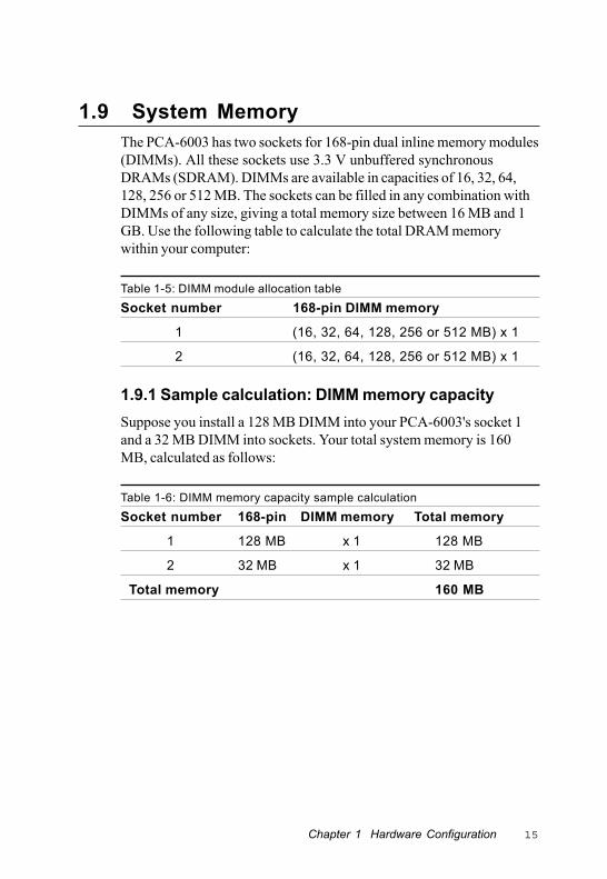
1.9 System MemoryThe PCA-6003 has two sockets for 168-pin dual inline memory modules(DIMMs). All these sockets use 3.3 V unbuffered synchronousDRAMs (SDRAM). DIMMs are available in capacities of 16, 32, 64,128, 256 or 512 MB. The sockets can be filled in any combination withDIMMs of any size, giving a total memory size between 16 MB and 1GB. Use the following table to calculate the total DRAM memorywithin your computer:
Table 1-5: DIMM module allocation tableSocket number 168-pin DIMM memory
1 (16, 32, 64, 128, 256 or 512 MB) x 1
2 (16, 32, 64, 128, 256 or 512 MB) x 1
1.9.1 Sample calculation: DIMM memory capacitySuppose you install a 128 MB DIMM into your PCA-6003's socket 1and a 32 MB DIMM into sockets. Your total system memory is 160MB, calculated as follows:
Table 1-6: DIMM memory capacity sample calculationSocket number 168-pin DIMM memory Total memory
1 128 MB x 1 128 MB
2 32 MB x 1 32 MB
Total memory 160 MB
16 PCA-6003 User's Manual
1.9.2 Supplementary information about DIMMsYour PCA-6003 can accept SDRAM memory chips with or withoutparity. Also note:
• If the PCA-6003 operates at 133/100 MHz, only use PC-133/ PC-100compliant DIMMs. Most systems will not even boot if non-compli-ant modules are used. This is due to strict timing issues involved atthis speed.
• SDRAM chips are usually thinner and have higher pin density thanEDO chips.
• Chips with 9 chips/side support ECC; chips with 8 chips/side do notsupport ECC.
1.10 Memory Installation ProceduresTo install DIMMs, first make sure the two handles of the DIMMsocket are in the "open" position. i.e. The handles lean outward.Slowly slide the DIMM module along the plastic guides on both endsof the socket. Then press the DIMM module right down into thesocket, until you hear a click. This is when the two handles haveautomatically locked the memory module into the correct position ofthe DIMM socket. To remove the memory module, just push bothhandles outward, and the memory module will be ejected by themechanism in the socket.
1.11 Cache MemorySince the second level (L2) cache has been embedded into the Intel®
Pentium III/Celeron processor, you do not have to take care of eitherSRAM chips or SRAM modules. The built-in second level cache in thePentium III/Celeron processor yields much higher performance thanthe external cache memories. The cache size in the Intel® Pentium IIIprocessor is 256 KB or 512 KB, for Celeron processor is 128 or 256 KB.

Chapter 1 Hardware Configuration 17
1.12 CPU InstallationThe CPU on the board must have a fan or heat sink attached, toprevent overheating.
Warning: Without a fan or heat sink, the CPU will overheat andcause damage to both the CPU and the mother-board.
To install a CPU, first turn off your system and remove its cover.Locate the processor socket 370.
1. Make sure the socket 370 lever is in the upright position. To raisethe lever, pull it out to the side a little and raise it as far as it will go.
2. Place the CPU in the empty socket. Follow the instructions thatcame with the CPU. If you have no instructions, complete thefollowing procedure. Carefully align the CPU so it is parallel to thesocket and the notches on the corners of the CPU correspond withthe notches on the inside of the socket. Gently slide the CPU in. Itshould insert easily. If it does not insert easily, pull the lever up alittle bit more.
3. Press the lever down. The plate will slide forward. You will feelsome resistance as the pressure starts to secure the CPU in thesocket. This is normal and will not damage the CPU.
When the CPU is installed, the lever should snap into place at the sideof the socket.
Note: To remove a CPU, pull the lever out to the side alittle and raise it as far as it will go. Lift out the CPU.

18 PCA-6003 User's Manual

Connecting Peripherals
This chapter tells how to connect periph-erals, switches and indicators to thePCA-6003 board. You can access most ofthe connectors from the top of the boardwhile it is installed in the chassis. If youhave a number of cards installed, or yourchassis is very tight, you may need topartially remove the card to make all theconnections.
2CHAPTER
20 PCA-6003 User's Manual
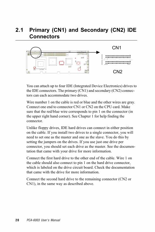
2.1 Primary (CN1) and Secondary (CN2) IDEConnectors
You can attach up to four IDE (Integrated Device Electronics) drives tothe IDE connectors. The primary (CN1) and secondary (CN2) connec-tors can each accommodate two drives.
Wire number 1 on the cable is red or blue and the other wires are gray.Connect one end to connector CN1 or CN2 on the CPU card. Makesure that the red/blue wire corresponds to pin 1 on the connector (inthe upper right hand corner). See Chapter 1 for help finding theconnector.
Unlike floppy drives, IDE hard drives can connect in either positionon the cable. If you install two drives to a single connector, you willneed to set one as the master and one as the slave. You do this bysetting the jumpers on the drives. If you use just one drive perconnector, you should set each drive as the master. See the documen-tation that came with your drive for more information.
Connect the first hard drive to the other end of the cable. Wire 1 onthe cable should also connect to pin 1 on the hard drive connector,which is labeled on the drive circuit board. Check the documentationthat came with the drive for more information.
Connect the second hard drive to the remaining connector (CN2 orCN1), in the same way as described above.
CN1
CN2

Chapter 2 Connecting Peripherals 21
2.2 Floppy Drive Connector (CN3)
You can attach up to two floppy disk drives to the PCA-6003'sonboard controller. You can use any combination of 5.25" (360 KB / 1.2MB) and/or 3.5" (720 KB / 1.44/2.88 MB) drives.
The card comes with a 34-pin daisy-chain drive connector cable. Onone end of the cable is a 34-pin flat-cable connector. On the other endare two sets of floppy disk drive connectors. The set on the end (afterthe twist in the cable) connects to the A: floppy drive. The set in themiddle connects to the B: floppy drive.
2.3 Parallel Port (CN4)
The parallel port is normally used to connect the CPU card to a printer.The onboard parallel port can be accessed through a 26-pin flat-cableconnector, CN4. The card comes with an adapter cable which lets youuse a traditional DB-25 connector. The cable has a 26-pin connector onone end and a DB-25 connector on the other, mounted on a retainingbracket. The bracket installs at the end of an empty slot in yourchassis, giving you access to the connector.
The parallel port is designated as LPT1, and can be disabled orchanged to LPT2 or LPT3 in the system BIOS setup.
CN3
CN4

22 PCA-6003 User's Manual
2.4 USB Port (CN6)
The PCA-6003 provides two USB (Universal Serial Bus) interfaces,which give complete Plug & Play and hot attach/detach for up to 127external devices.The USB interface complies with USB SpecificationRev. 1.0 and is fuse-protected.
The USB interface is accessed through a 10-pin flat-cable connector,CN6. The adapter cable has a 10-pin connector on one end and twoUSB connectors on the bracket.
The USB interface can be disabled in the system BIOS setup.
2.5 VGA Connector (CN7)
The PCA-6003 includes a AGP SVGA interface that can drive conven-tional CRT displays. CN7 is a standard 15-pin D-SUB connectorcommonly used for VGA. Pin assignments for CRT connector CN7 aredetailed in Appendix B.
To install the bracket, find an empty slot in your chassis. Unscrew theplate that covers the end of the slot. Screw in the bracket in place ofthe plate. Next, attach the flat-cable connector to CN4 on the CPU card.Wire 1 of the cable is red or blue, and the other wires are gray. Makesure that wire 1 corresponds to pin 1 of CN4. Pin 1 is on the upper rightside of CN4.
CN6
CN7
Pin 1

Chapter 2 Connecting Peripherals 23
2.6 10/100Base-T Ethernet Connector (CN8)
The PCA-6003 is equipped with a high-performance 32-bit PCI-busEthernet interface, which is fully compliant with IEEE 802.3/u 10/100Mbps CSMA/CD standards. It is supported by all major networkoperating systems and is 100% Novell NE-2000 compatible. Anonboard RJ-45 jack provides convenient 10/100Base-T RJ-45 opera-tion.
2.7 Serial Ports (CN9: COM1; CN10: COM2)
The PCA-6003 offers two serial ports, CN9 as COM1 and CN10 asCOM2. These ports can connect to serial devices, such as a mouse orprinters, or to a communication network.
Table 2-1: Serial port connections (COM1, COM2)Connector Ports Address Interrupt
CN9 COM1 3F8*, 3E8 IRQ4
CN10 COM2 2F8*, 2E8 IRQ3
* default settings
CN8
CN9CN10
24 PCA-6003 User's Manual
The IRQ and address ranges for both ports are fixed. However, if youwant to disable the port or change these parameters later, you can dothis in the system BIOS setup.
Different devices implement the RS-232 standard in different ways. Ifyou are having problems with a serial device, be sure to check the pinassignments for the connector.
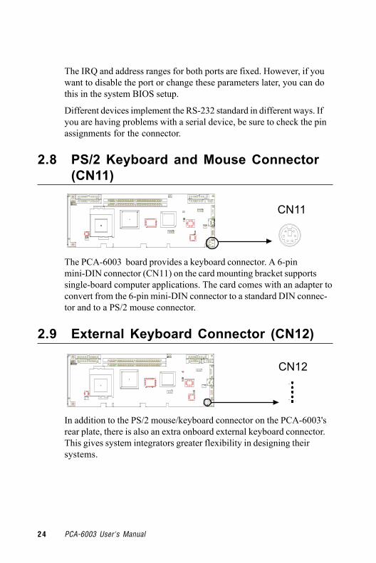
2.8 PS/2 Keyboard and Mouse Connector(CN11)
The PCA-6003 board provides a keyboard connector. A 6-pinmini-DIN connector (CN11) on the card mounting bracket supportssingle-board computer applications. The card comes with an adapter toconvert from the 6-pin mini-DIN connector to a standard DIN connec-tor and to a PS/2 mouse connector.
2.9 External Keyboard Connector (CN12)
In addition to the PS/2 mouse/keyboard connector on the PCA-6003'srear plate, there is also an extra onboard external keyboard connector.This gives system integrators greater flexibility in designing theirsystems.
CN11
CN12
Chapter 2 Connecting Peripherals 25
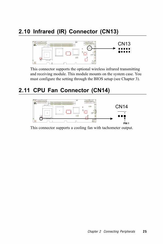
2.10 Infrared (IR) Connector (CN13)
This connector supports the optional wireless infrared transmittingand receiving module. This module mounts on the system case. Youmust configure the setting through the BIOS setup (see Chapter 3).
2.11 CPU Fan Connector (CN14)
This connector supports a cooling fan with tachometer output.
CN13
CN14
PIN 1

26 PCA-6003 User's Manual
2.12 Front Panel Connectors (CN16, CN17,CN18, CN19, CN21 and CN29)
There are several external switches to monitor and control thePCA-6003.
2.12.1 Keyboard lock and power LED (CN16)CN16 is a 5-pin connector for the keyboard lock and power on LED.Refer to Appendix B for detailed information on the pin assignments. Ifa PS/2 or ATX power supply is used, the system's power LED statuswill be as indicated below:
Table 2-2: PS/2 or ATX power supply LED statusPower mode LED (PS/2 power) LED (ATX power)
System On On On
System Suspend Fast flashes Fast flashes
System Off Off Slow flashes
2.12.2 External speaker (CN17)CN17 is a 4-pin connector for an extenal speaker. If there is no externalspeaker, the PCA-6003 provides an onboard buzzer as an alternative.To enable the buzzer, set pins 3-4 as closed.
CN19
CN16
CN29CN17
CN18CN21

Chapter 2 Connecting Peripherals 27
2.12.3 Reset (CN18)Many computer cases offer the convenience of a reset button.Connect the wire from the reset button.
2.12.4 HDD LED (CN19)You can connect an LED to connector CN19 to indicate when the HDDis active.
2.12.5 SM Bus Connector (CN29)This connector is reserved for Advantech's SNMP-1000 HTTP/SNMPRemote System Manager. The SNMP-1000 allows users to monitor theinternal voltages, temperature and fans from a remote computerthrough an Ethernet network.
CN23 can be connected to CN3 or CN6 of SNMP-1000. Please becareful about the pin assignments, pin 1 must be connected to pin 1and pin2 to pin 2 on both ends of cable.
2.12.6 Connecting to SNMP-1000 remote managerUse the 6-pin to 8-pin cable to connect the CPU card to SNMP-1000.This cable comes with the SNMP-1000.
1
1
CN21 CN18
CPU Card
CN19 CN29
SNMP-1000
CN19
PIN 1PIN 1

28 PCA-6003 User's Manual
2.13 ATX Power Control Connectors (CN20and CN21)
CN20
2.13.1 ATX feature connector (CN20) and soft power switchconnector (CN21)The PCA-6003 can support an advanced soft power switch function ifan ATX power supply is used. To enable the soft power switchfunction:
1. Take the specially designed ATX-to-PS/2 power cable out of theaccessory bag.
2. Connect the 3-pin plug of the cable to CN20 (ATX feature connec-tor).
3. Connect the power on/off button to CN21. (A momentary type ofbutton should be used.)
Note: If you will not be using an ATX power connector,make sure that pins 2-3 of CN20 are closed.
Warnings: 1. Make sure that you unplug your power supplywhen adding or removing expansion cards or othersystem components. Failure to do so may causesevere damage to both your CPU card and expan-sion cards.
2. ATX power supplies may power on if certainmotherboard components or connections are touchedby metallic objects.
Chapter 2 Connecting Peripherals 29
Important: Make sure that the ATX power supply can take atleast a 720 mA load on the 5 V standby lead (5VSB).If not, you may have difficulty powering on yoursystem and/or supporting the "Wake-on-LAN"function.
2.13.2 Controlling the soft power switchUsers can also identify the current power mode through the system'spower LED (see Section 2.13.1).
2.14 LCD Connector (CN41)This 40-pin connector supports an 18-bit TFT LCD.
2.15 LCD Inverter Power Connector (CN42)The LCD inverter is connectoed to CN42 via a 5-pin connector toprovide +12 V power to the LCD display. The pin ssignments for CN42can be found in Appendix B.
2.16 AC-97 Audio Interface (CN43)This interface can be used to connect to the PCA-AUDIO audioextension module for the audio function.

30 PCA-6003 User's Manual

Award BIOS Setup
This chapter describes how to set thecard’s BIOS configuration data.
CH
APT
ER3

32 PCA-6003 User’s Manual
3.1 IntroductionAward’s BIOS ROM has a built-in setup program that allows users tomodify the basic system configuration. This type of information isstored in battery-backed memory (CMOS RAM) so that it retains thesetup information when the power is turned off.
3.2 Entering SetupTurn on the computer and check for the “patch code”. If there is anumber assigned to the patch code, it means that the BIOS supportsyour CPU.
If there is no number assigned to the patch code, please contactAdvantech’s applications engineer to obtain an up-to-date patch codefile. This will ensure that your CPU’s system status is valid.
After ensuring that you have a number assigned to the patch code,press <Del> to allow you to enter the setup.
Figure 3-1: Award BIOS Setup initial screen

Chapter 3 Award BIOS Setup 33
3.3 Standard CMOS SetupChoose the “Standard CMOS Features” option from the “Initial SetupScreen” menu, and the screen below will be displayed. This menuallows users to configure system components such as date, time, harddisk drive, floppy drive, display, and memory.
Figure 3-2: Standard CMOS features screen
3.3.1 CMOS RAM backupThe CMOS RAM is powered by an onboard button cell battery.
When BIOS CMOS Setup has been completed, CMOS RAM data isautomatically backed up to Flash ROM. If conditions in a harshindustrial enviroment cause a soft error, BIOS will recheck the data andautomatically restore the original data for booting.
Note: If you intend to update CMOS RAM data, you haveto click on “DEL” within two seconds of the “CMOSchecksum error....” display screen message appear-ing. Then enter the “Setup” screen to modify the data.If the “CMOS checksum error....” message appearsagain and again, please check to see if you need toreplace the battery in your system.

34 PCA-6003 User’s Manual
3.4 Advanced BIOS FeaturesThe “Advanced BIOS Features” screen appears when choosing the“Advanced BIOS Features” item from the “Initial Setup Screen”menu. It allows the user to configure the CPU card according to hisparticular requirements.
Below are some major items that are provided in the Advanced BIOSFeatures screen.
A quick booting function is provided for your convenience. Simplyenable the Quick Booting item to save yourself valuable time.
Figure 3-3: Advanced BIOS features screen
3.4.1 Virus WarningIf enabled, a warning message and alarm beep activates if someoneattempts to write here. The commands are “Enabled” or “Disabled.”
3.4.2 CPU Internal Cache / External CacheEnabling this feature speeds up memory access. The commands are“Enabled” or “Disabled.”
Chapter 3 Award BIOS Setup 35
3.4.3 CPU L2 Cache ECC CheckingEnabling allows CPU L2 cache checking. The commands are “Enabled”or “Disabled.”
3.4.4 First/Second/Third/Other Boot DeviceThe BIOS tries to load the OS with the devices in the sequenceselected.
Choices are: Floppy, LS/ZIP, HDD, SCSI, CDROM, LAN, Disabled.
3.4.5 Swap Floppy DriveLogical name assignments of floppy drives can be swapped if there ismore than one floppy drive. The commands are “Enabled” or “Dis-abled.”
3.4.6 Boot UP Floppy SeekSelection of the command “Disabled” will speed the boot up. Selectionof “Enabled” searches disk drives during boot up.
3.4.7 Boot Up NumLock Status This feature selects the “power on” state for NumLock. The com-mands are “Enabled” or “Disabled.”
3.4.8 Gate A20 OptionNormal The A20 signal is controlled by the keyboard
controller.
Fast (Default) The A20 signal is controlled by the chipset.
3.4.9 Typematic Rate SettingThe typematic rate is the rate key strokes repeat as determined by thekeyboard controller. The commands are “Enabled” or “Disabled.”Enabling allows the typematic rate and delay to be selected.

36 PCA-6003 User’s Manual
3.4.10 Typematic Rate (Chars/Sec)BIOS accepts the following input values (characters/second) fortypematic rate: 6, 8, 10, 12, 15, 20, 24, 30.
3.4.11 Typematic Delay (msec)Typematic delay is the time interval between the appearance of twoconsecutive characters, when holding down a key. The input valuesfor this category are: 250, 500, 750, 1000 (msec).
3.4.12 Security OptionThis setting determines whether the system will boot up if thepassword is denied. Access to Setup is, however, always limited.
System The system will not boot, and access to Setup will bedenied if the correct password is not entered at the prompt.
Setup The system will boot, but access to Setup will be denied ifthe correct password is not entered at the prompt.
Note: To disable security, select “PASSWORD SETTING”in the main menu. At this point, you will be asked toenter a password. Simply press <Enter> to disablesecurity. When security is disabled, the system willboot, and you can enter Setup freely.
3.4.13 OS Select for DRAM > 64MBThis setting allows selecting an OS with greater than 64MB of RAM.Commands are “Non-OS2” or “OS2.”
3.4.14 Video BIOS ShadowEnable copies video BIOS to sharow RAM for performnace improving.Choices are Enable, Disable.
3.4.15 Small Logo (EPA)ShowEnergy Star Log from Environmental Protection Agency. Choices are:Enable, Disable.

Chapter 3 Award BIOS Setup 37
3.5 Advanced Chipset FeaturesBy choosing the “Advanced Cipset Features” option from the “InitialSetup Screen” menu, the screen below will be displayed. This samplescreen contains the manufacturer’s default values for this CPU card, asshown in Figure 3-5:
Note: DRAM default timings have been carefully chosenand should ONLY be changed if data is being lost.Please first contact technical support.
Figure 3-4: Advanced chipset features screen
3.5.1 DRAM ClockThis item allows you to control the DRAM speed. The Choice: HostClock, CLK-33M.
3.5.2 SDRAM Cycle LengthWhen synchronous DRAM is installed, the number of clock cycles ofCAS latency depends on the DRAM timing. Do not reset this fieldfrom the default value specified by the system designer. The Choice:2, 3.

38 PCA-6003 User’s Manual
3.5.3 Bank InterleaveThis item allows you to select the value in this field, depending onwhether the board has paged DRAMs or EDO (extended data output)DRAMs. The Choice: EDO 50ns, EDO 60ns,Slow, Medium, Fast,Turbo.
3.5.4 Memory HoleIn order to improve performance, certain space in memory is reservedfor ISA cards. This memory must be mapped into the memory spacebelow 16MB. The Choice: 15M-16M, Disabled.
3.5.5 P2C/P2P ConcurrencyThis item allows you to enable/disable the PCI to CPU, CPU to PCIconcurrency. The Choice: Enabled, Disabled
3.5.6 System BIOS CacheableSelecting Enabled allows caching of the system BIOS ROM at F0000h-FFFFFh, resulting in better system performance. However, if anyprogram writes to this memory area, a system error may result. Thechoice: Enabled, Disabled.
3.5.7 AGP Aperture SizeSelect the size of Accelerated Graphics Port (AGP) aperture. Theaperture is a portion of the PCI memory address range dedicated forgraphics memory address space. Host cycles that hit the aperturerange are forwarded to the AGP without any translation. The Choice:4M, 8M, 16M, 32M, 65M, 128M, 256M.
3.5.8 Onchip USBThis should be enabled if your system has a USB installed on thesystem board and you want to use it. Even when so equipped, if youadd a higher performance controller, you will need to disable thisfeature. The choice: Enabled, Disabled.

Chapter 3 Award BIOS Setup 39
3.5.9 USB Keyboard SupportSelect Enabled if your system contains a Universal Serial Bus (USB)controller and you have a USB keyboard. The choice: Enabled,Disabled.
3.5.10 USB Mouse SupportSelect Enabled if your system contains a Universal Serial Bus (USB)controller and you have a USB mouse. The choice: Enabled, Disabled.
3.5.11 CPU to PCI Write BufferWhen this field is Enabled, writes from the CPU to the PCI bus arebuffered, to compensate for the speed differences between the CPUand the PCI bus. When Disabled, the writes are not buffered and theCPU must wait until the write is complete before starting another writecycle. The choice: Enabled, Disabled.
3.5.12 PCI Dynamic BurstingWhen Enabled, every write transaction goes to the write buffer.Burstable transactions then burst on the PCI bus and nonburstabletransactions don’t. The choice: Enabled, Disabled
3.5.13 PCI Master 0 WS WriteWhen Enabled, writes to the PCI bus are executed with zero waitstates. The choice: Enabled, Disabled
3.5.14 PCI Delay TransactionThe chipset has an embedded 32-bit posted write buffer to supportdelay transactions cycles. Select Enabled to support compliance withPCI specification version 2.1. The choice: Enabled, Disabled
3.5.15 PCI#2 Access #1 RetryWhen disabled, PCI#2 will not be disconnected until access finishes(difault). When enabled, PCI#2 will be disconnected if max retries areattempted without success. The choice: Enabled, Disabled

40 PCA-6003 User’s Manual
3.5.16 AGP Master 1 WS WriteWhen Enabled, writes to the AGP(Accelerated Graphics Port) areexecuted with one wait states. The choice: Enabled, Disabled
3.5.17 Memory Parity/ ECC CheckEnabled add a parity check to the boot-up memory test. SelectEnabled when only system DRAM contains parity. The Choice:Enable, Disable.
3.6 Integrated Peripherals
Figure 3-5: Integrated peripherals
3.6.1 On-Chip Primary/Secondary PCI IDEIf you enable IDE HDD Block Mode, the enhanced IDE driver will beenabled. Leave IDE HDD Block Mode on the default setting.
3.6.2 IDE Primary Master/Slave PIO/UDMA Mode,IDE Secondary Master/Slave PIO/UDMA Mode (Auto)Each channel (Primary and Secondary) has both a master and a slave,making four IDE devices possible. Because each IDE device may havea different Mode timing (0, 1, 2, 3, 4), it is necessary for these to beindependent. The default setting “Auto” will allow autodetection toensure optimal performance.

Chapter 3 Award BIOS Setup 41
3.6.3 Init Display FirstThis item allows you to choose which one to activate first, PCI Slot orAGP. The choices: PCI Slot, AGP.
3.6.4 IDE HDD Block ModeBlock mode is also called block transfer, multiple commands, ormultiple sector read/write. If your IDE hard drive supports block mode(most new drives do), select Enabled for automatic detection of theoptimal number of block read/writes per sector the drive can support.
The choice: Enabled, Disabled
3.6.5 Onboard FDD ControllerWhen enabled, this field allows you to connect your floppy diskdrives to the onboard floppy disk drive connector instead of aseparate controller card. If you want to use a different controller cardto connect the floppy disk drives, set this field to Disabled.
3.6.6 Onboard Serial Port 1 (3F8H/IRQ4)The settings are Auto 3F8/IRQ4, 2F8/IRQ3, 3E8/IRQ4, 2E8/IRQ3, andDisabled for the on-board serial connector.
3.6.7 Onboard Serial Port 2 (2F8H/IRQ3)The settings are Auto 3F8/IRQ4, 2F8/IRQ3, 3E8/IRQ4, 2E8/IRQ3, andDisabled for the on-board serial connector.
3.6.8 UART 2 Mode SelectThis item allows you to select UART mode. The choices: HPSIR,ASKIR, Standard.
3.6.9 Onboard Parallel Port (378H/IRQ7)This field sets the address of the on-board parallel port connector. Youcan select either 3BC/IRQ7, 378/IRQ7, 278/IRQ5 or Disabled. If youinstall an I/O card with a parallel port, make sure there is no conflict in
42 PCA-6003 User’s Manual
the address assignments. The CPU card can support up to threeparallel ports, as long as there are no conflicts for each port.
3.6.10 Onboard Parallel Port Mode (ECP + EPP)This field allows you to set the operation mode of the parallel port.The setting “Normal” allows normal speed operation, but in onedirection only. “EPP” allows bidirectional parallel port operation atmaximum speed. “ECP” allows the parallel port to operate in bidirec-tional mode and at a speed faster than the maximum data transfer rate.“ECP + EPP” allows normal speed operation in a two-way mode.
3.6.11 ECP Mode Use DMAThis selection is available only if you select “ECP” or “ECP + EPP” inthe Parallel Port Mode field. In ECP Mode Use DMA, you can selectDMA channel 1, DMA channel 3, or Disable. Leave this field on thedefault setting.
3.6.12 EPP Mode SelectThis field allows you to select EPP port type 1.7 or 1.9. The choices:EPP1.7, 1.9.

Chapter 3 Award BIOS Setup 43
3.7 Power Management SetupThe power management setup controls the CPU card’s “green”features to save power. The following screen shows the manufactur-er’s defaults:
Figure 3-6: Power management setup screen
3.7.1 ACPI functionThis item allows you to enable/disable the Advanced Configurationand Power Management (ACPI). The choice: Enabled, Disabled.
3.7.2 Power ManagementThis category allows you to select the type (or degree) of powersaving and is directly related to the following modes:
1. HDD Power Down
2. Doze Mode
3. Suspend Mode
There are four selections for Power Management, three of which havefixed mode settings.

44 PCA-6003 User’s Manual
nOsyawlA sedomgnivasrewopgnirudnoniamerlliwrotinoM
ffO>---NdnepsuS .edomdnepsuSehtsretnesmetsysehtnehwdeknalbrotinoM
ffO>---NybtS,psuS .sedomybdnatSrodnepsuSrehtiesretnemetsysehtnehwdeknalbrotinoM
ffO>ÑsedoMllA .edomgnivasrewopynasretnemetsysehtnehwdeknalbrotinoM
3.7.5 Video Off MethodThis determines the manner in which the monitor is blanked.
knalB+CNYSH/V latnozirohdnalacitrevehtffonrutotmetsysehtesuaclliwnoitcelessihT.reffuboedivehtotsknalbetirwdnastropnoitazinorhcnys
neercSknalB .reffuboedivehtotsknalbsetirwylnonoitposihT
SMPD tnemeganaMrewoPyalpsiDehtstroppusrotinomruoyfinoitposihttceleStcelesotsdradnatSscinortcelEoediVehtfodradnats)SMPD(gnilangiS
.seulavtnemeganamrewopoediv
)tluafed(elbasiD sedomruofllaselbasiD.tnemeganamrewopoN
gnivaSrewoP.niM ,.rh1=edoMybdnatS.rh1=edoMezoD.tnemeganamrewopmuminiM.nim51=nwoDrewoPDDHdna,.rh1=edoMdnepsuS
gnivaSrewoP.xaM 1=edoMybdnatS,.nim1=edoMezoD.tnemeganamrewopmumixaM.nim1=nwoDrewoPDDHdna,.nim1=edoMdnepsuS,.nim
denifeDresU ehtfohcae,delbasidtonnehW.yllaudividniedomhcaetesotuoyswollAsegnarhcihwnwoDrewoPDDHroftpecxe.rh1ot.nim1morferasegnar
.elbasiddna.nim51ot.nim1morf
3.7.3 PM Control by APMWhen enabled, an Advanced Power Management device will beactivated to enhance the Max. Power Saving mode and stop the CPUinternal clock. If Advance Power Management (APM) is installed onyour system, selecting Yes gives better power savings. If the Max.Power Saving is not enabled, this will be preset to No.
3.7.4 Video Off OptionWhen enabled, this feature allows the VGA adapter to operate in apower saving mode.

Chapter 3 Award BIOS Setup 45
3.7.6 MODEM Use IRQThis determines the IRQ in which the MODEM can use.The choices: 3,4, 5, 7, 9, 10, 11, NA.
3.7.7 Soft-Off by PWRBTNIf you choose “Instant-Off”, then pushing the ATX soft power switchbutton once will switch the system to “system off” power mode. Youcan choose “Delay 4 sec.” If you do so, then pushing the button formore than 4 seconds will turn off the system, whereas pushing thebutton momentarily (for less than 4 seconds) will switch the system to“suspend” mode.
3.7.8 State After Power FailureThis field lets you to determine the state that your computer returnsafter a power failure. If sets to Off, the PC will not boot after a powerfailure. If sets to On, the PC will restart after a power failure. If sets toAuto, the PC will go back to the previous state before a power failureoccurred. For instance, if the PC is power-on when power system fails,the PC will restart when power system is working again. If the PC ispower-ff when power system fails, the PC will not boot when powersystem is working again. The Choice: Off, On, Auto.

46 PCA-6003 User’s Manual
Figure 3-7: Wake-up event screen
3.8.1 VGAWhen Enabled, you can set the VGA awakens the system.
3.8.2 LPT & COMWhen On of LPT & COM, any activity from one of the listed systemperipheral devices or IRQs wakes up the system.
3.8.3 HDD & FDDWhen On of HDD & FDD, any activity from one of the listed systemperipheral devices wakes up the system.
3.8.4 Power On by LANThis shows you to wake up the system via LAN from the remote host.The Choice: Enable, Disable.
3.8 Wake Up Event

Chapter 3 Award BIOS Setup 47
3.8.5 Power On by ModemWhen enabled, an input signal on the serial Ring Indicator (RI) line (inother words, an incoming call on the modem) awakens the system froma soft off state. The Choice: Enable, Disable.
3.8.6 Power On by AlarmWhen enabled, you can set the date and time at which the RTC (real-time clock) alarm awakens the system from Suspend mode. TheChoice: Enable, Disable.
48 PCA-6003 User’s Manual
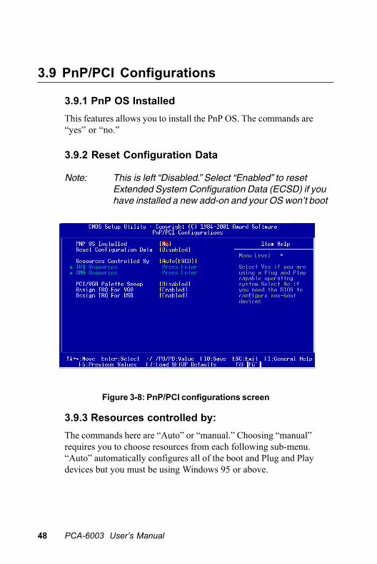
Figure 3-8: PnP/PCI configurations screen
3.9 PnP/PCI Configurations
3.9.1 PnP OS InstalledThis features allows you to install the PnP OS. The commands are“yes” or “no.”
3.9.2 Reset Configuration Data
Note: This is left “Disabled.” Select “Enabled” to resetExtended System Configuration Data (ECSD) if youhave installed a new add-on and your OS won’t bootand you need to reconfigure.
3.9.3 Resources controlled by:The commands here are “Auto” or “manual.” Choosing “manual”requires you to choose resources from each following sub-menu.“Auto” automatically configures all of the boot and Plug and Playdevices but you must be using Windows 95 or above.

Chapter 3 Award BIOS Setup 49
3.10 PC Health Status
Figure 3-9: PC health status screen
3.10.1 Current CPU TemperatureThis shows you the current CPU1 temperature.
3.10.2 Current CPUFAN SpeedThis shows you the current CPUFAN speed.
3.10.5 VCOREThis shows CPU1 core voltage.
3.10.7 +2.5/ +3.3V/ + 5V/ +12VThis shows you the voltage of +2.5/ +3.3V/ + 5V/ +12V

50 PCA-6003 User’s Manual
3.11 Load Setup Defaults“LOAD SETUP DEFAULTS” loads the values required by the systemfor maximum performance.
3.12 Password SettingTo change the password:
1. Choose the “Set Password” option from the “Initial Setup Screen”menu and press <Enter>.
The screen will display the following message:
Press <Enter>.
2. If the CMOS is good or if this option has been used to change thedefault password, the user is asked for the password stored in theCMOS. The screen will display the following message:
Enter the current password and press <Enter>.
3. After pressing <Enter> (ROM password) or the current password(user-defined), you can change the password stored in the CMOS.The password must be no longer than eight (8) characters.
Remember, to enable the password setting feature, you must firstselect either “Setup” or “System” from the “Advanced BIOS Fea-tures” menu.
Confirm Password:
Enter Password:

3.13 Save & Exit SetupIf you select this and press <Enter>, the values entered in the setuputilities will be recorded in the CMOS memory of the chipset. Themicroprocessor will check this every time you turn your system onand compare this to what it finds as it checks the system. This recordis required for the system to operate.
3.14 Exit Without SavingSelecting this option and pressing <Enter> lets you exit the setupprogram without recording any new values or changing old ones.

52 PCA-6003 User’s Manual
AGP SVGA Setup
The PCA-6003 features an integratedAGP/VGA interface. This chapter providesinstructions for installing and operatingthe software drivers on the display driverCD included in your package.
CH
APT
ER4

54 PCA-6003 User's Manual
4.1 Before You BeginTo facilitate the installation of the enhanced display device drivers andutility software, you should read the instructions in this chaptercarefully before you attempt installation. The enhanced displaydrivers for the PCA-6003 board are located on the software installationCD. You must install the drivers and utility software by using thesupplied SETUP program for DOS drivers.
Note: The files on the software installation CD are com-pressed. Do not attempt to install the drivers bycopying the files manually. You must use the suppliedSETUP program to install the drivers.
Before you begin, it is important to note that most display driversneed to have the relevant software application already installed in thesystem prior to installing the enhanced display drivers. In addition,many of the installation procedures assume that you are familiar withboth the relevant software applications and operating system com-mands. Review the relevant operating system commands and thepertinent sections of your application software’s user’s manual beforeperforming the installation.
4.2 Features• Chipset integrated high performance 3D graphic engine
• High speed internal AGP bus mastering data bus
• PC 99 compliant
• Support DVD playback & hardware motion compensation
• Integrated 230 MHz DAC allows 16M colors at 1600 x 1200 resolu-tion
• User-friendly installation for Windows 95 and Windows NT
• AGP 1.0 interface
• Share system SDRAM up to 8 MB.

Chapter 4 PCI SVGA Setup 55
4.3 InstallationFirst, insert CD drive. Then follow the Icons for your PCA Series modelnumber.
Click on the right driver for the auto-installation.
Please follow the instruction of the installation program to install theVGA driver and to restart the system when the installation is finished.

56 PCA-6003 User's Manual

LAN Configuration
The PCA-6003 features an onboard LANinterface. This chapter gives detailedinformation on Ethernet configuration. Itshows you how to configure the card tomatch your application requirements.
CH
APT
ER5
58 PCA-6003 User's Manual
5.1 IntroductionThe PCA-6003 features an optional 32-bit 10/100 Mbps Ethernetnetwork interface. This interface supports bus mastering architectureand auto-negotiation features. Therefore standard twisted-pair cablingwith RJ-45 connectors for both 10 Mbps and 100 Mbps connectionscan be used. Extensive driver support for commonly-used networksystems is also provided.
5.2 Features• Realtek RTL8139C Ethernet LAN controller
(fully integrated 10Base-T/100Base-TX)
• Supports Wake-on-LAN remote control function
• Supports up to128 K bytes Boot ROM
• PCI Bus Master complies with PCI Rev. 2.2
• MAC & PHY (10/100 Mbps) interfaces
• Complies to IEEE 802.3X 10Base-T and IEEE 802.3u 100Base-Tinterfaces
• 3.3 V power supply with 5 V tolerant I/Os
• Single RJ-45 connector gives auto-detection of 10 Mbps or 100Mbps network data transfer rates and connected cable types
• Enhancements on ACPI, PCI power management
• Compliant to PC99 standard
Chapter 5 LAN Configuration 59
5.3 Driver InstallationThe PCA-6003's onboard Ethernet interface supports all major networkoperating systems.
The BIOS automatically detects the LAN while booting, and assignsan IRQ level and I/O address. No jumpers or switches are required foruser configuration.
The drivers and installation instructions are located in the followingdirectories of the utility CD:
• Dos: Drivers for DOS platforms
• Info: Installation instructions
• Nwserver: Drivers for Novell NetWare
• Wfw: Drivers for Windows 3.11 for Workgroups
Please refer to the text files in the Info directory for detailed informa-tion about installing the drivers.
Note: Operating system vendors may post driver updateson their websites. Please visit the websites of OSvendors to download updated drivers.

60 PCA-6003 User's Manual
5.4 Windows 9X Drivers SetupProcedure
Note 1: If you are using Windows 98SE, your system will findthe LAN device "PCI Ethernet Controller". You mustfirst remove this device from your system, and thenrestart your computer. Then you will be ready toinstall the correct driver by following the procedurebelow.
Note 2: The CD-ROM drive is designated as "D" throughoutthis section.
1. In the "Windows" screen, click on "Start" and select "Settings".Then click on the "Control Panel" icon to select "System".

Chapter 5 LAN Configuration 61
2. In the "System Properties" window, select the "Device Manager"tab. Select "View devices by type", and navigate to:Computer\Other devices\PCI Ethernet Controller. Highlight "PCIEthernet Controller" and click on "Properties".

62 PCA-6003 User's Manual
3. In the "PCI Ethernet Controller Properties" window, select the"Driver" tab. Then click on "Update Driver...".
4. In the "Update Device Driver Wizard" window, click on "Next".

Chapter 5 LAN Configuration 63
5. Click "Next".
6. In the following "Update Device Driver Wizard" window, select"Specify a location:". Type in: "D:\Drv_LAN\RTL8139C\WIN98".Then click on "Next".
64 PCA-6003 User's Manual
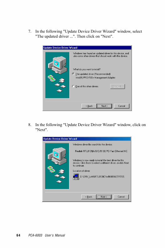
7. In the following "Update Device Driver Wizard" window, select"The updated driver ...". Then click on "Next".
8. In the following "Update Device Driver Wizard" window, click on"Next".

Chapter 5 LAN Configuration 65
9. When the "Insert Disk" window appears, insert the utility CD intothe CD-ROM drive. Then click on "OK".
10. When the "Update Device Driver Wizard" window shows, click onfinish.
11. In the "System Settings change" window, select click on "Yes".
66 PCA-6003 User's Manual
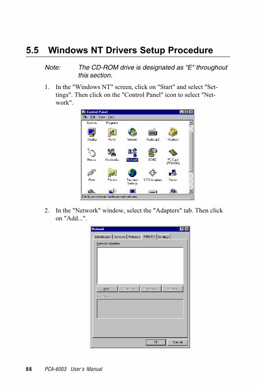
5.5 Windows NT Drivers Setup Procedure
Note: The CD-ROM drive is designated as "E" throughoutthis section.
1. In the "Windows NT" screen, click on "Start" and select "Set-tings". Then click on the "Control Panel" icon to select "Net-work".
2. In the "Network" window, select the "Adapters" tab. Then clickon "Add...".

Chapter 5 LAN Configuration 67
3. In the "Select Network Adapter" window, click on "Have Disk...".
4. When the "Insert Disk" window appears, insert the utility CD intothe CD-ROM drive. The correct file path is;D:\Drv_LAN\RTL8139C\WINNT4. When you have the correct filepath, click on "OK".

68 PCA-6003 User's Manual
5. In the "Select OEM Option" window, click on "OK".
6. In the "Duplex mode", click "OK".

Chapter 5 LAN Configuration 69
8. In the "Microsoft TCP/IP Properties" window, select the "IPAddress" tab. Then select "Specify an IP address". Type in the IPAddress and Subnet Mask details. Then click on "OK".
7. In the "Network" window, select the "Adapters" tab. Under"Network Adapters:", highlight "Realtek RTL8139CA/B/C(8130).

70 PCA-6003 User's Manual
9. In the "Network Settings Change" window, click on "Yes".
Chapter 5 LAN Configuration 71
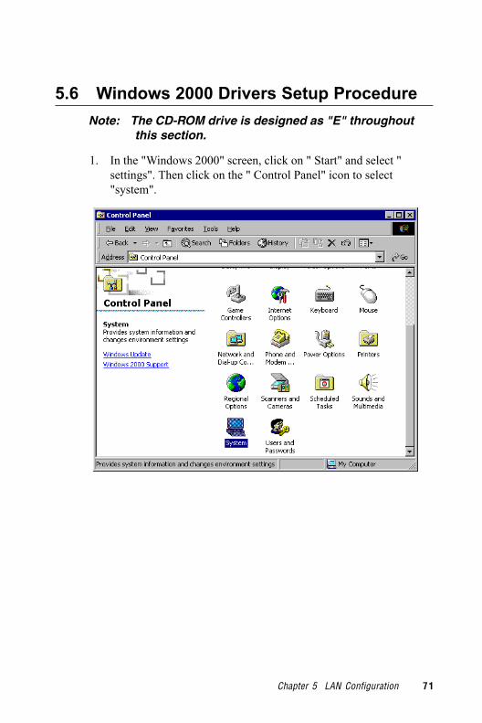
5.6 Windows 2000 Drivers Setup Procedure Note: The CD-ROM drive is designed as "E" throughout this section.
1. In the "Windows 2000" screen, click on " Start" and select "settings". Then click on the " Control Panel" icon to select"system".

72 PCA-6003 User's Manual
2. In the " System Properties" window, select the " Device Manag-er".

Chapter 5 LAN Configuration 73
3. In "Device Manager" screen, follow the screen instructions, toclick on "Properties".
4. In the following screen, to click on "Update Driver".

74 PCA-6003 User's Manual
5. Click on "Next".
6. Following the highlighted item, and click on "Next".

Chapter 5 LAN Configuration 75
7. Click on "Have Disk".
8. Key in "E:\Drv__LAN\RTL8139C\WIN2000", then click on "OK".

76 PCA-6003 User's Manual
9. To highlight the following item, and click "Next".
10. Click "Next".

Chapter 5 LAN Configuration 77
11. Click "Finish" to complete the installation.

78 PCA-6003 User's Manual

Programming theWatchdog Timer
The PCA-6003 is equipped with a watch-dog timer that resets the CPU or generatesan interrupt if processing comes to astandstill for any reason. This featureensures system reliability in industrialstandalone or unmanned environments.
AAPP
END
IX

80 PCA-6003 User's Manual
A.1 Programming the Watchdog TimerTo program the watchdog timer, you must write a program whichwrites I/O port address 443 (hex). The output data is a time intervalvalue. The value range is from 01 (hex) to 3F (hex), and the relatedtime interval is 1 sec. to 63 sec.
Data Time Interval
01 1 sec.
02 2 sec.
03 3 sec.
04 4 sec.
• •
• •
• •
3F 63 sec.

Appendix A Programming the Watchdog Timer 81
After data entry, your program must refresh the watchdog timer byrewriting I/O port 443 (hex) while simultaneously setting it. Whenyou want to disable the watchdog timer, your program should read I/Oport 443 (hex).
The following example shows how you might program the watchdogtimer in BASIC:10 REM Watchdog timer example program20 OUT &H443, data REM Start and restart the watchdog30 GOSUB 1000 REM Your application task #1,40 OUT &H443, data REM Reset the timer50 GOSUB 2000 REM Your application task #2,60 OUT &H443, data REM Reset the timer70 X=INP (&H443) REM Disable the watchdog timer80 END1000 REM Subroutine #1, your application task• •• •• •1070 RETURN2000 REM Subroutine #2, your application task• •• •• •2090 RETURN

82 PCA-6003 User's Manual

Pin AssignmentsThis appendix contains information of adetailed or specialized nature. It includes:
• IDE Hard Drive Connector• Floppy Drive Connector• Parallel Port Connector• SCSI Connector• USB Connector• VGA Connector• Ethernet 10/100Base-T RJ-45
Connector• COM1/COM2 RS-232 Serial Port• Keyboard and Mouse Connector• External Keyboard Connector• IR Connector• CPU Fan Power Connector• Power LED and Keylock Connector• External Speaker Connector• Reset Connector• HDD LED Connector• ATX Feature Connector• ATX Soft Power Switch• SM Bus Connector• Extension I/O Board Connector• System I/O Ports• DMA Channel Assignments• Interrupt Assignments• 1st MB Memory Map
APP
END
IX B

84 PCA-6003 User's Manual
B.1 IDE Hard Drive Connector (CN1, CN2)
Table B-1: IDE hard drive connector (CN1, CN2)
Pin Signal Pin Signal
1 IDE RESET* 2 GND
3 DATA 7 4 DATA 8
5 DATA 6 6 DATA 9
7 DATA 5 8 DATA 10
9 DATA 4 10 DATA 11
11 DATA 3 12 DATA 12
13 DATA 2 14 DATA 13
15 DATA 1 16 DATA 14
17 DATA 0 18 DATA 15
19 SIGNAL GND 20 N/C
21 DISK DMA REQUEST 22 GND
23 IO WRITE 24 GND
25 IO READ 26 GND
27 IO CHANNEL READY 28 GND
29 HDACKO* 30 GND
31 IRQ14 32 N/C
33 ADDR 1 34 N/C
35 ADDR 0 36 ADDR 2
37 HARD DISK SELECT 0* 38 HARD DISK SELECT 1*
39 IDE ACTIVE* 40 GND
* low active
402
1 39
4
3 37
38

Appendix B Pin Assignments 85
B.2 Floppy Drive Connector (CN3)
Table B-2: Floppy drive connector (CN3)
Pin Signal Pin Signal
1 GND 2 FDHDIN*
3 GND 4 N/C
5 N/C 6 FDEDIN*
7 GND 8 INDEX*
9 GND 10 MOTOR 0*
11 GND 12 DRIVE SELECT 1*
13 GND 14 DRIVE SELECT 0*
15 GND 16 MOTOR 1*
17 GND 18 DIRECTION*
19 GND 20 STEP*
21 GND 22 WRITE DATA*
23 GND 24 WRITE GATE*
25 GND 26 TRACK 0*
27 GND 28 WRITE PROTECT*
29 GND 30 READ DATA*
31 GND 32 HEAD SELECT*
33 GND 34 DISK CHANGE*
* low active
434
33 3
32
31 1
2

86 PCA-6003 User's Manual
B.3 Parallel Port Connector (CN4)
Table B-3: Parallel port connector (CN4)
Pin Signal Pin Signal
1 STROBE* 14 AUTOFD*
2 D0 15 ERR
3 D1 16 INIT*
4 D2 17 SLCTINI*
5 D3 18 GND
6 D4 19 GND
7 D5 20 GND
8 D6 21 GND
9 D7 22 GND
10 ACK* 23 GND
11 BUSY 24 GND
12 PE 25 GND
13 SLCT 26 N/C
* low active
1526
13 2
25
12 1
14

Appendix B Pin Assignments 87
B.4 USB Connector (CN6)
Table B-4: USB1/USB2 connector (CN6)
Pin USB1 Signal Pin USB2 Signal
1 +5 V 6 +5 V
2 UV- 7 UV-
3 UV+ 8 UV+
4 GND 9 GND
5 Chassis GND 10 N/C
B.5 VGA Connector (CN7)
Table B-5: VGA connector (CN7)
Pin Signal Pin Signal
1 RED 9 VCC
2 GREEN 10 GND
3 BLUE 11 N/C
4 N/C 12 SDT
5 GND 13 H-SYNC
6 GND 14 V-SYNC
7 GND 15 SCK
8 GND
732
8
1 6
910
45
5
15
1
1110 6

88 PCA-6003 User's Manual
B.6 Keyboard and Mouse Connnector(CN11)
Table B-6: Keyboard and mouse connector (CN11)Pin Signal1 KB DATA2 MS DATA3 GND4 VCC
5 KB CLOCK6 MS CLOCK
B.7 External Keyboard Connector (CN12)
Table B-7: External keyboard connector (CN12)
Pin Signal1 CLK2 DATA3 NC4 GND5 VCC
5
3
12
4
6

Appendix B Pin Assignments 89
B.8 IR Connector (CN13)
Table B-8: IR connector (CN13)
Pin Signal Pin Signal1 +5 V 2 N/C3 FIRRX 4 CIRRX5 IR_RX 6 +5VSB7 GND 8 N/C9 IR_TX 10 N/C
B.9 CPU Fan Power Connector (CN14)
Table B-9: CPU fan power connector (CN14)
Pin Signal
1 GND
2 +12 V
3 Detect
8
57
6
9 3
24
1
10
1

90 PCA-6003 User's Manual
B.10 Power LED and Keylock Connector(CN16)
You can use an LED to indicate when the CPU card is on. Pin 1 ofCN16 supplies the LED's power, and Pin 3 is the ground.
You can use a switch (or a lock) to disable the keyboard so that thePC will not respond to any input. This is useful if you do not wantanyone to change or stop a program which is running. Simplyconnect the switch from Pin 4 to Pin 5 of CN16.
Table B-10: Power LED and keylock connector (CN16)
Pin Function
1 LED power (+5 V)
2 NC
3 GND
4 Keyboard lock
5 GND
B.11 External Speaker Connector (CN17)The CPU card has its own buzzer. You can also connect it to theexternal speaker on your computer chassis.
Table B-11: External speaker (CN17)
Pin Function
1 +5 VCC
2 GND
3 Internal buzzer
4 Speaker out
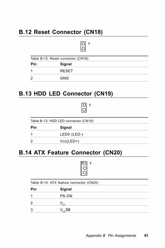
Appendix B Pin Assignments 91
B.12 Reset Connector (CN18)
Table B-12: Reset connector (CN18)
Pin Signal
1 RESET
2 GND
B.13 HDD LED Connector (CN19)
Table B-13: HDD LED connector (CN19)
Pin Signal
1 LED0 (LED-)
2 Vcc(LED+)
B.14 ATX Feature Connector (CN20)
Table B-14: ATX feature connector (CN20)
Pin Signal
1 PS-ON
2 VCC
3 VCCSB
1
1
1

92 PCA-6003 User's Manual
B.15 ATX Soft Power Switch (CN21)
Table B-15: ATX soft power switch (CN21)
Pin Signal
1 5VSB
2 PWR-BTN
B.16 SM Bus Connector (CN29)
Table B-16: SM Bus Connector (CN29)
Pin Signal
1 SMB_DATA
2 SMB_CLK
1
1
user
SMB_CLK
user
SMB_DATA

Appendix B Pin Assignments 93
B.17 18-bit LCD Display Connector (CN41)
Table B-17: 18-bit LCD display connector
Pin Signal Pin Signal1 VDDSAFE5 2 VDDSAFE53 GND 4 GND5 VDDSAFE3 6 VDDSAFE37 Vcon 8 GND9 NC 10 NC11 P17 (B0) 12 P16 (B1)13 P11 (B2) 14 P10 (B3)15 P9 (B4) 16 P8 (B5)17 NC 18 NC19 P15 (G0) 20 P14 (G1)21 P7 (G2) 22 P6 (G3)23 P5 (G4) 24 P4 (G5)25 NC 26 NC27 P13 (R0) 28 P12 (R1)29 P3 (R2) 30 P2 (R3)31 P1 (R4) 32 P0 (R5)33 GND 34 GND35 SFCLK 36 FLM37 M 38 LP39 ENBKL 40 ENAVEE
Note: The model number of the CN41 socket isDF13A-40DP-1.25V (Hirose Electric Co., Ltd.)
1
2
3
4
38 37
3940

94 PCA-6003 User's Manual
B.18 Flat panel inverter power connector(CN42)
Table B-18
1 +12 V
2 GND
3 ENBKL
4 VBR
5 VCC
B.19 AC-97 Audio Interface (CN43)
Table B-19
1 VCC 2 GND
3 SYNC 4 BITCLK
5 SDOUT 6 SDIN
7 SDIN2 8 -ACRST
9 +12V 10 GND
11 GND 12 NC
321
45
7
32
8
1
6
9 10
45
11 12

Appendix B Pin Assignments 95
B.20 System I/O Ports
Table B-20: System I/O ports
Addr. range (Hex) Device000-01F DMA controller020-021 Interrupt controller 1, master022-023 Chipset address040-05F 8254 timer060-06F 8042 (keyboard controller)070-07F Real-time clock, non-maskable interrupt (NMI)
mask080-09F DMA page register0A0-0BF Interrupt controller 20C0-0DF DMA controller0F0 Clear math co-processor0F1 Reset math co-processor0F8-0FF Math co-processor1F0-1F8 Fixed disk200-207 Game I/O278-27F Parallel printer port 2 (LPT3)290-297 On-board hardware monitor2F8-2FF Serial port 2300-31F Prototype card360-36F Reserved378-37F Parallel printer port 1 (LPT2)380-38F SDLC, bisynchronous 23A0-3AF Bisynchronous 13B0-3BF Monochrome display and printer adapter (LPT1)3C0-3CF Reserved3D0-3DF Color/graphics monitor adapter3F0-3F7 Diskette controller3F8-3FF Serial port 12E-2F Watchdog timer
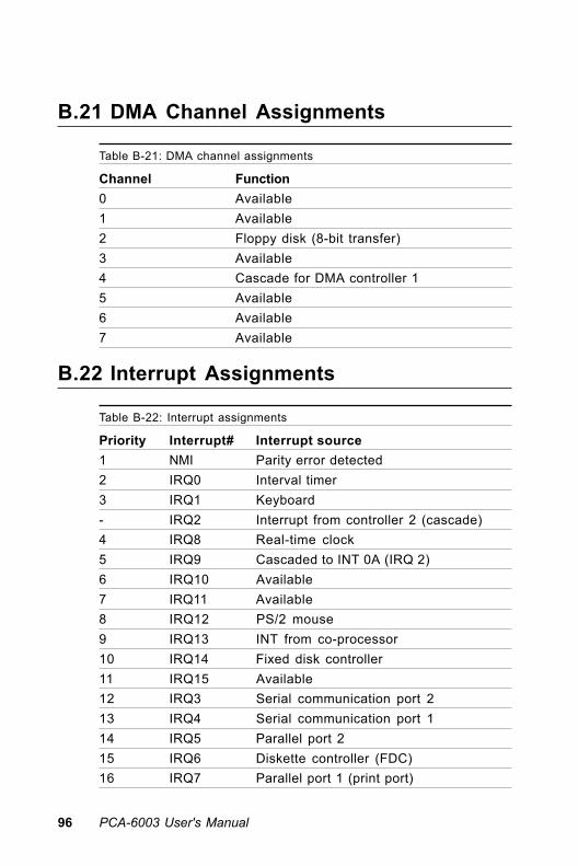
96 PCA-6003 User's Manual
B.21 DMA Channel Assignments
Table B-21: DMA channel assignments
Channel Function0 Available1 Available2 Floppy disk (8-bit transfer)3 Available4 Cascade for DMA controller 15 Available6 Available7 Available
B.22 Interrupt Assignments
Table B-22: Interrupt assignments
Priority Interrupt# Interrupt source1 NMI Parity error detected2 IRQ0 Interval timer3 IRQ1 Keyboard- IRQ2 Interrupt from controller 2 (cascade)4 IRQ8 Real-time clock5 IRQ9 Cascaded to INT 0A (IRQ 2)6 IRQ10 Available7 IRQ11 Available8 IRQ12 PS/2 mouse9 IRQ13 INT from co-processor10 IRQ14 Fixed disk controller11 IRQ15 Available12 IRQ3 Serial communication port 213 IRQ4 Serial communication port 114 IRQ5 Parallel port 215 IRQ6 Diskette controller (FDC)16 IRQ7 Parallel port 1 (print port)

Appendix B Pin Assignments 97
B.23 1st MB Memory Map
Table B-23: 1st MB memory map
Addr. range (Hex) Device
F0000h - FFFFFh System ROM
CC000h - EFFFFh Unused
C0000h - CBFFFh VGA BIOS
B8000h - BFFFFh CGA/EGA/VGA text
B0000h - B7FFFh Unused
A0000h - AFFFFh EGA/VGA graphics
00000h - 9FFFFh Base memory
B.24 PCI Bus Map
Table B-24: PCI bus map
Function Signals:Device ID INT# pin GNT# pin
Onboard LAN1 AD21 INT C GNT E
PCI slot 1 AD31 INT B, C, D, A GNT A
PCI slot 2 AD30 INT C, D, A, B GNT B
PCI slot 3 AD29 INT D, A, B, C GNT C
PCI slot 4 AD28 INT A, B, C, D GNT D

98 PCA-6003 User's Manual