Pc200 8 completa
15
* This model was designed for Papercraft and may differ from the original in some respects. Special Vehicle Series : 02 Hydraulic Excavator Assembly Instructions View of completed model T ools ools Assembly tip ssembly tip Key to symbols Key to symbols Scissors Ruler, set square Glue (Wood glue or craft glue recommend) Exhausted ballpoint pen (out of ink) Toothpicks (for use in applying glue) Tweezers (useful for handling small parts) Pencil Pattern Red dot Green dot Blue dot Assembly instructions Solid line Dashed and dotted line Dotted line Solid red line Diagonal grey lines Mountain fold Fold so that the printed pattern faces outside. Fold so that the printed pattern faces inside. Valley fold Cut parts out along this line. Cut a notch along this line. Cut these areas out. Glue parts with the same number together. (Numbers are not printed on very small parts.) Glue areas within the same part together. Glue Insert Glue tab Reverse side of paper (without gluing) Red arrow Blue arrow Light blue Light grey Glue, scissors and other tools may be dangerous to young children so be sure to keep them out of the reach of young children. Assembly Instructions: Six A4 sheets (No. 1 to No. 6) Build this model with careful reference to the Assembly Instructions. Write the number of each part on the reverse side of the part in pencil upon cutting it out, to be sure you can tell which part is which later. Before gluing, crease the paper along mountain and valley fold lines. Trace along the folds with a ruler and an exhausted ballpoint pen (out of ink) to get a sharper fold. Make sure rounded sections are nice and stiff. Glue to the reverse side of the specified part. The dots show where to glue the pieces together. Glue the pieces together as shown in the following examples. Some parts must be glued together along the cut surfaces. This denotes a part that must be able to move after themodel is completed.Be sure to crease these parts sufficiently. Movable part
-
Upload
david-cabrerizo-calvo -
Category
Automotive
-
view
1.008 -
download
3
Transcript of Pc200 8 completa
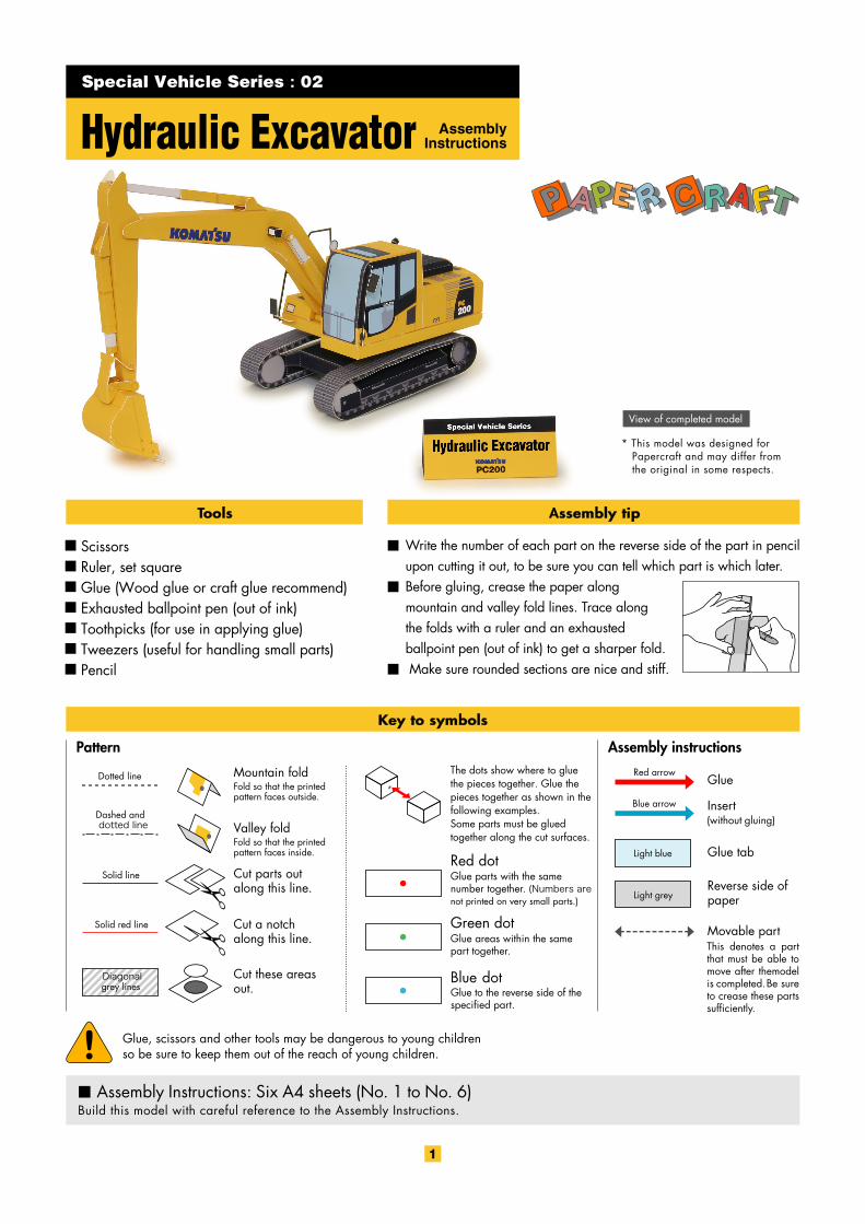
* This model was designed for Papercraft and may differ from the original in some respects.
Special Vehicle Series : 02
Hydraulic Excavator AssemblyInstructions
View of completed model
Toolsools Assembly tipssembly tip
Key to symbolsKey to symbols
ScissorsRuler, set squareGlue (Wood glue or craft glue recommend)Exhausted ballpoint pen (out of ink)Toothpicks (for use in applying glue)Tweezers (useful for handling small parts)Pencil
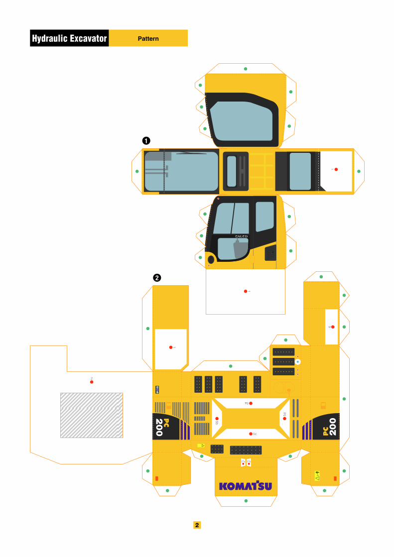
Pattern
Red dot
Green dot
Blue dot
Assembly instructions
Solid line
Dashed and dotted line
Dotted line
Solid red line
Diagonalgrey lines
Mountain foldFold so that the printed pattern faces outside.
Fold so that the printed pattern faces inside.
Valley fold
Cut parts out along this line.
Cut a notch along this line.
Cut these areas out.
Glue parts with the same number together. (Numbers are not printed on very small parts.)
Glue areas within the same part together.
Glue
Insert
Glue tab
Reverse side of paper
(without gluing)
Red arrow
Blue arrow
Light blue
Light grey
Glue, scissors and other tools may be dangerous to young children so be sure to keep them out of the reach of young children.
Assembly Instructions: Six A4 sheets (No. 1 to No. 6)Build this model with careful reference to the Assembly Instructions.
Write the number of each part on the reverse side of the part in pencilupon cutting it out, to be sure you can tell which part is which later.Before gluing, crease the paper along mountain and valley fold lines. Trace along the folds with a ruler and an exhausted ballpoint pen (out of ink) to get a sharper fold. Make sure rounded sections are nice and stiff.
Glue to the reverse side of the specified part.
The dots show where to glue the pieces together. Glue the pieces together as shown in the following examples.Some parts must be glued together along the cut surfaces.
This denotes a part that must be able to move after themodel is completed.Be sure to crease these parts sufficiently.
Movable part
Front Rear
Cross section
Assembly InstructionsHydraulic Excavator
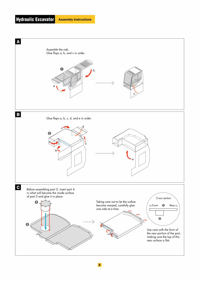
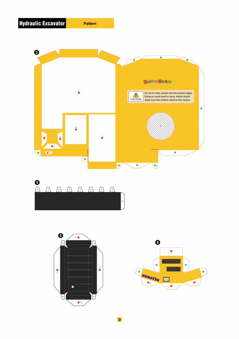
Assemble the cab. Glue flaps a, b, and c in order.
Before assembling part 3, insert part 4 in what will become the inside surface of part 3 and glue it in place.
Taking care not to let the outline become warped, carefully glue one side at a time.
Use care with the form of the rear portion of the part, making sure the top of this rear surface is flat.
Glue flaps a, b, c, d, and e in order.

noitces ssorCnoitces ssorC
Cross section
Cross section
Moving partCross section
Moving part
Crosssection
Note the needed gaps.
Assembly InstructionsHydraulic Excavator
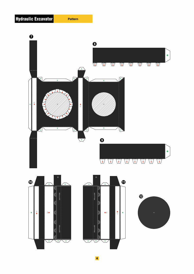
Assemble part 7 and then insert part 8 from the bottom and glue it in place.
When assembling these pieces, be very careful to ensure the mountain and valley folds are as shown in the illustration. Insert the pieces after checking the fit.
Insert part 9 to the inside of part 8 and glue it in place.
Glue part 12 in place to cover the hole and glue spot.
Take care to glue the components of this piece together in the order shown.
Cross section Cross section
Cross section
Cross sectionInsideOutside
Outside
Inside
Inside
Outside
OutsideInside
Assembly InstructionsHydraulic Excavator
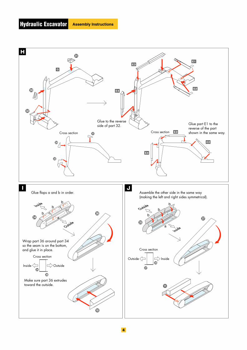
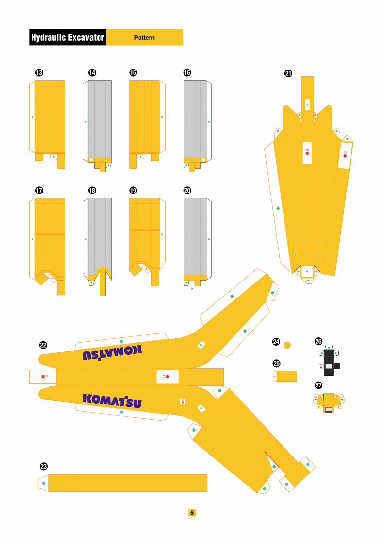
Glue to the reverse side of part 32.
Wrap part 36 around part 34 so the seam is on the bottom, and glue it in place.
Glue flaps a and b in order. Assemble the other side in the same way (making the left and right sides symmetrical).
Make sure part 36 extrudes toward the outside.
Glue part E1 to the reverse of the part shown in the same way.
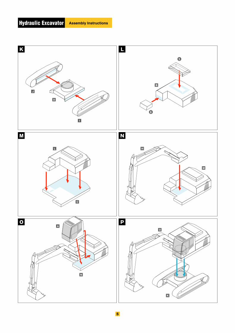
Assembly InstructionsHydraulic Excavator
Hydraulic Excavator
Assembly InstructionsHydraulic Excavator
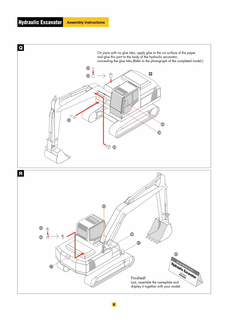
On parts with no glue tabs, apply glue to the cut surface of the paper and glue this part to the body of the hydraulic excavator, concealing the glue tabs.(Refer to the photograph of the completed model.)
Finished!Last, assemble the nameplate and display it together with your model.
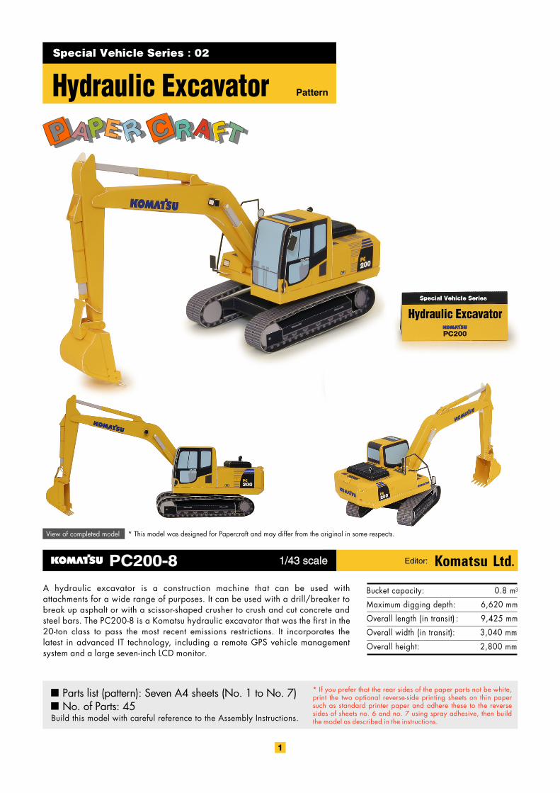
Bucket capacity:
Maximum digging depth:
Overall length (in transit) :
Overall width (in transit):
Overall height:
0.8 m3
6,620 mm
9,425 mm
3,040 mm
2,800 mm
Special Vehicle Series : 02
PatternHydraulic Excavator
View of completed model * This model was designed for Papercraft and may differ from the original in some respects.
A hydraulic excavator is a construction machine that can be used with attachments for a wide range of purposes. It can be used with a drill/breaker to break up asphalt or with a scissor-shaped crusher to crush and cut concrete and steel bars. The PC200-8 is a Komatsu hydraulic excavator that was the first in the 20-ton class to pass the most recent emissions restrictions. It incorporates the latest in advanced IT technology, including a remote GPS vehicle management system and a large seven-inch LCD monitor.
Parts list (pattern): Seven A4 sheets (No. 1 to No. 7)No. of Parts: 45
Build this model with careful reference to the Assembly Instructions.
* If you prefer that the rear sides of the paper parts not be white, print the two optional reverse-side printing sheets on thin paper such as standard printer paper and adhere these to the reverse sides of sheets no. 6 and no. 7 using spray adhesive, then build the model as described in the instructions.
PC200-8PC200-8 1/43 scale1/43 scale Editor:
PatternHydraulic Excavator
PatternHydraulic Excavator
CAUTION
Do not hit other people with the pointed edges.Doing so could result in injury. Adults should make sure that children observe this caution.
PatternHydraulic Excavator
PatternHydraulic Excavator
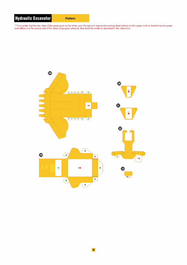
PatternHydraulic Excavator* If you prefer that the rear sides of the paper parts not be white, print the optional reverse-side printing sheet (yellow) on thin paper such as standard printer paper and adhere it to the reverse side of this sheet using spray adhesive, then build the model as described in the instructions.
Hydraulic ExcavatorSpecial Vehicle Series
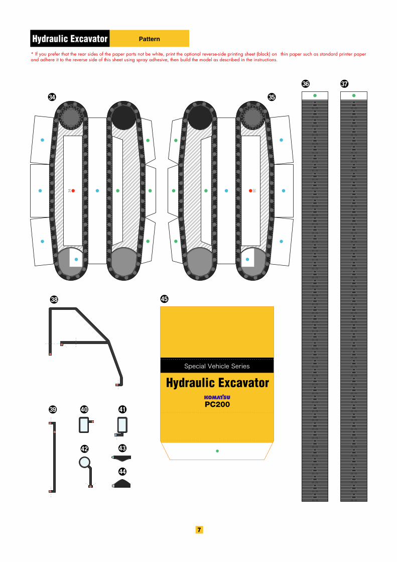
PatternHydraulic Excavator* If you prefer that the rear sides of the paper parts not be white, print the optional reverse-side printing sheet (black) on thin paper such as standard printer paper and adhere it to the reverse side of this sheet using spray adhesive, then build the model as described in the instructions.

Hydraulic ExcavatorHydraulic Excavator Optional reverse-side printing sheet (yellow)
Print this sheet on thin paper such as standard printer paper and adhere it to the reverse side of sheet no. 6 using spray adhesive, then build the model as described in the instructions. There's no need to worry about which end of this sheet points up and which points down.

Hydraulic ExcavatorHydraulic Excavator Optional reverse-side printing sheet (black)
Print this sheet on thin paper such as standard printer paper and adhere it to the reverse side of sheet no. 7 using spray adhesive, then build the model as described in the instructions. There's no need to worry about which end of this sheet points up and which points down.