PC-DMIS Enterprise Metrology · PDF fileA metrology software package could use CAD master...
24
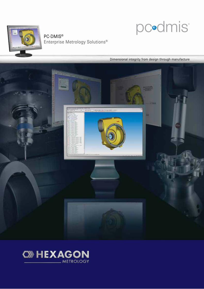
PC-DMIS ® Enterprise Metrology Solutions ® Dimensional integrity from design through manufacture
-
Upload
truongkhanh -
Category
Documents
-
view
221 -
download
2
Transcript of PC-DMIS Enterprise Metrology · PDF fileA metrology software package could use CAD master...
PC-DMIS®
Enterprise Metrology Solutions®
Dimensional integrity from design through manufacture
2
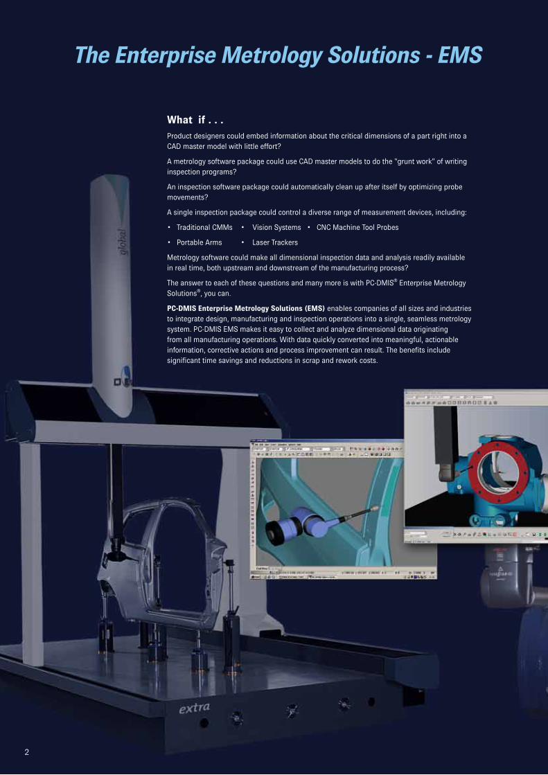
What if . . .Product designers could embed information about the critical dimensions of a part right into a CAD master model with little effort?
A metrology software package could use CAD master models to do the “grunt work” of writing inspection programs?
An inspection software package could automatically clean up after itself by optimizing probe movements?
A single inspection package could control a diverse range of measurement devices, including:
• Traditional CMMs • Vision Systems • CNC Machine Tool Probes
• Portable Arms • Laser Trackers
Metrology software could make all dimensional inspection data and analysis readily available in real time, both upstream and downstream of the manufacturing process?
The answer to each of these questions and many more is with PC-DMIS® Enterprise Metrology Solutions®, you can.
PC-DMIS Enterprise Metrology Solutions (EMS) enables companies of all sizes and industries to integrate design, manufacturing and inspection operations into a single, seamless metrology system. PC-DMIS EMS makes it easy to collect and analyze dimensional data originating from all manufacturing operations. With data quickly converted into meaningful, actionable information, corrective actions and process improvement can result. The benefits include significant time savings and reductions in scrap and rework costs.
2
The Enterprise Metrology Solutions - EMS
3
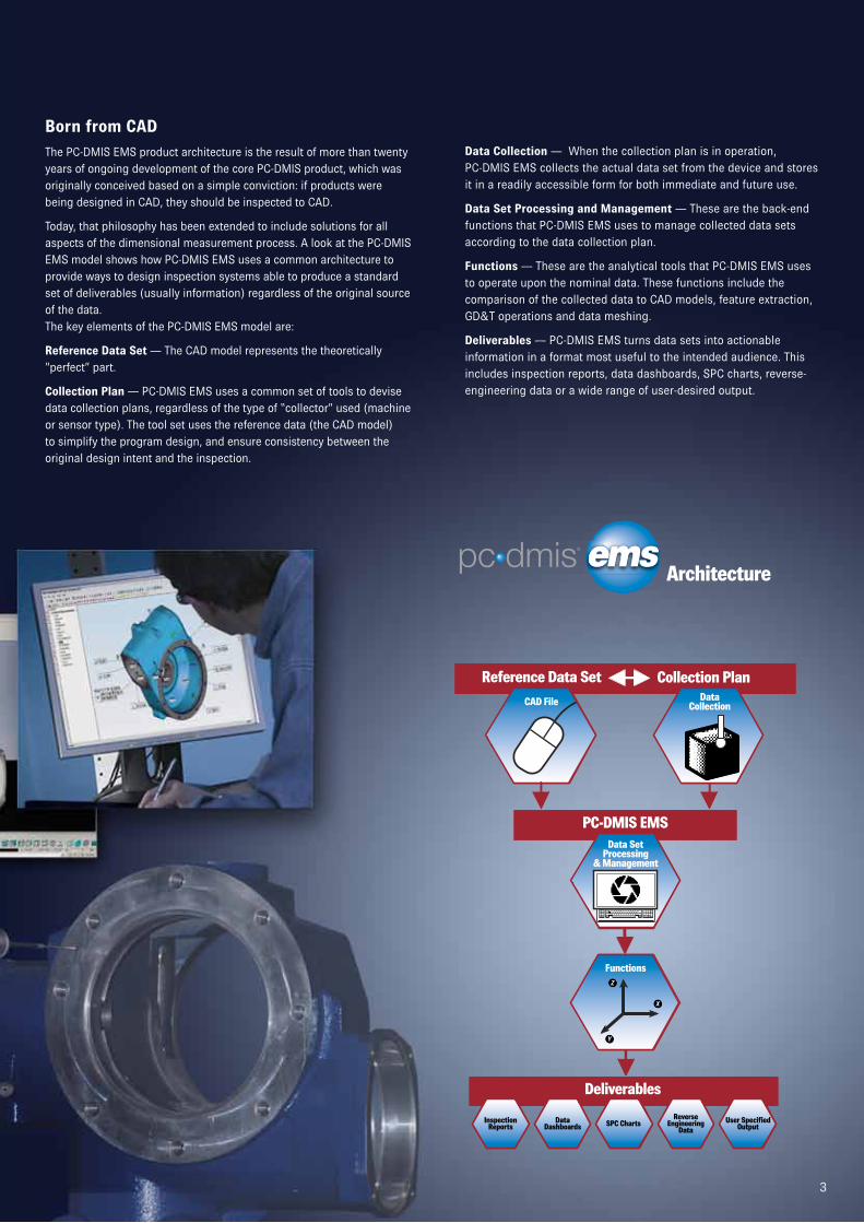
Born from CADThe PC-DMIS EMS product architecture is the result of more than twenty years of ongoing development of the core PC-DMIS product, which was originally conceived based on a simple conviction: if products were being designed in CAD, they should be inspected to CAD.
Today, that philosophy has been extended to include solutions for all aspects of the dimensional measurement process. A look at the PC-DMIS EMS model shows how PC-DMIS EMS uses a common architecture to provide ways to design inspection systems able to produce a standard set of deliverables (usually information) regardless of the original source of the data. The key elements of the PC-DMIS EMS model are:
Reference Data Set — The CAD model represents the theoretically “perfect” part.
Collection Plan — PC-DMIS EMS uses a common set of tools to devise data collection plans, regardless of the type of “collector” used (machine or sensor type). The tool set uses the reference data (the CAD model) to simplify the program design, and ensure consistency between the original design intent and the inspection.
Data Collection — When the collection plan is in operation, PC-DMIS EMS collects the actual data set from the device and stores it in a readily accessible form for both immediate and future use.
Data Set Processing and Management — These are the back-end functions that PC-DMIS EMS uses to manage collected data sets according to the data collection plan.
Functions — These are the analytical tools that PC-DMIS EMS uses to operate upon the nominal data. These functions include the comparison of the collected data to CAD models, feature extraction, GD&T operations and data meshing.
Deliverables — PC-DMIS EMS turns data sets into actionable information in a format most useful to the intended audience. This includes inspection reports, data dashboards, SPC charts, reverse-engineering data or a wide range of user-desired output.
3
Y
Z
X
Y
Z
X
Reference Data Set Collection Plan
PC-DMIS EMS
CAD File Data Collection
Data SetProcessing
& Management
Functions
Y
Z
X
Deliverables
InspectionReports
DataDashboards SPC Charts
Reverse Engineering
DataUser Specified
Output
Architecture
4
Tools for Building Metrology Systems —Closing the Loop Between Manufacturing and Design
Enterprise Metrology Solutions for Process Control and ImprovementWith PC-DMIS EMS, a metrology information system can be tailored to meet the specific requirements of any manufacturer. The PC-DMIS EMS product suite is an integrated group of metrology software products based upon a common technology, making it flexible and powerful.
With PC-DMIS EMS, manufacturers can build metrology capabilities into multiple stages of the production process from design through manufacture. This interaction at multiple stages of production improves information availability and allows data-driven decision making that can improve manufacturing operations.
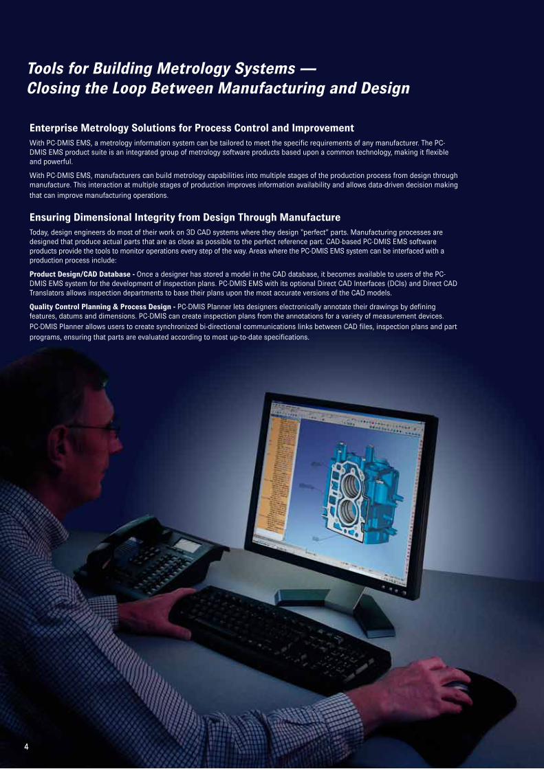
Ensuring Dimensional Integrity from Design Through ManufactureToday, design engineers do most of their work on 3D CAD systems where they design “perfect” parts. Manufacturing processes are designed that produce actual parts that are as close as possible to the perfect reference part. CAD-based PC-DMIS EMS software products provide the tools to monitor operations every step of the way. Areas where the PC-DMIS EMS system can be interfaced with a production process include:
Product Design/CAD Database - Once a designer has stored a model in the CAD database, it becomes available to users of the PC-DMIS EMS system for the development of inspection plans. PC-DMIS EMS with its optional Direct CAD Interfaces (DCIs) and Direct CAD Translators allows inspection departments to base their plans upon the most accurate versions of the CAD models.
Quality Control Planning & Process Design - PC-DMIS Planner lets designers electronically annotate their drawings by defining features, datums and dimensions. PC-DMIS can create inspection plans from the annotations for a variety of measurement devices. PC-DMIS Planner allows users to create synchronized bi-directional communications links between CAD files, inspection plans and part programs, ensuring that parts are evaluated according to most up-to-date specifications.
4
5
SPC-Erfassung und -Analyse
Herstellung
PC-DMIS DCI/DCT
Produktions- Feedback-Modell
Produkt-Design
Gestaltung des Messverfahrens
Programmierer-Schnittstelle PC-DMIS
Datenerfassungsmethoden
Nahezu in Echtzeit
Produktionsstät-ten-Überprüfung
Messen im Offline-Betrieb
PC-DMIS-Schnittstelle Reporting
CAD-Datei
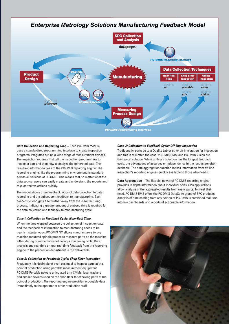
Data Collection and Reporting Loop – Each PC-DMIS module uses a standardized programming interface to create inspection programs. Programs run on a wide range of measurement devices. The inspection routines first tell the inspection program how to inspect a part and then how to analyze the generated data. The resultant information goes to the PC-DMIS reporting engine. The reporting engine, like the programming environment, is standard across all versions of PC-DMIS. This means that no matter what the data source, users can easily create and understand the reports and take corrective actions quickly.
The model shows three feedback loops of data collection to data reporting and the subsequent feedback to manufacturing. Each concentric loop gets a bit further away from the manufacturing process, indicating a greater amount of elapsed time is required for the data collection and feedback-to-manufacturing cycle.
Case 1: Collection to Feedback Cycle: Near-Real Time
When the time elapsed between the collection of inspection data and the feedback of information to manufacturing needs to be nearly instantaneous, PC-DMIS NC allows manufacturers to use machine-mounted spindle probes to measure parts on the machine either during or immediately following a machining cycle. Data analysis and real-time or near real-time feedback from the reporting engine to the production department is the deliverable.
Case 2: Collection to Feedback Cycle: Shop Floor Inspection
Frequently it is desirable or even essential to inspect parts at the point of production using portable measurement equipment. PC-DMIS Portable powers articulated arm CMMs, laser trackers and similar devices used on the shop floor for checking parts at the point of production. The reporting engine provides actionable data immediately to the operator or other production staff.
Case 3: Collection to Feedback Cycle: Off-Line Inspection
Traditionally, parts go to a Quality Lab or other off-line station for inspection and this is still often the case. PC-DMIS CMM and PC-DMIS Vision are the typical solution. While off-line inspection has the longest feedback cycle, the advantages of accuracy or independence in the results are often desirable. The data aggregation function makes information from off-line inspection’s reporting engines quickly available to those who need it.
Data Aggregation – The flexible, powerful PC-DMIS reporting engine provides in-depth information about individual parts. SPC applications allow analysis of the aggregated results from many parts. To meet that need, PC-DMIS EMS offers the PC-DMIS DataSuite group of SPC products. Analysis of data coming from any edition of PC-DMIS is combined real-time into live dashboards and reports of actionable information.
5
Enterprise Metrology Solutions Manufacturing Feedback Model
6
PC-DMIS Environment —Scalable, Flexible Programming Tools
Enhancing Productivity and Quality Through Consistency, Scalability and Flexibility
PC-DMIS EMS provides manufacturers of all sizes with a tightly integrated suite of metrology software products. Working seamlessly together, its modules present a consistent look and feel across the full range of measurement operations including inspection planning, program development, part measurement, results analysis, report generation, and report distribution.
CAD is Key
CAD has always been an integral part of PC-DMIS EMS. Using CAD:
• Designers embed their intent into CAD.
• Programmers develop their inspection routines using CAD.
• Measurement software compares results to CAD.
• Reports can include CAD for ease of interpretation.
• Measurement results return to CAD for further reverse engineering and additional evaluation.
PC-DMIS EMS products offer a variety of links to CAD. Most include translators for the major neutral CAD standards (IGES, STEP, etc.). For the most exacting applications, Direct CAD Interfaces (DCIs) and Direct CAD Translators (DCTs) are available for all major CAD systems.
A Direct CAD Interface (DCI) — Works directly on the native CAD model, accessed through the CAD database, without translation, and is the most accurate representation of the original model. Using DCI occupies a seat on the CAD system.
A Direct CAD Translator (DCT) — Converts the CAD model directly from its native format into PC-DMIS format without using a neutral translation format for greater accuracy. It does not occupy a seat on the CAD system.
PC-DMIS EMS Measurement Products
All PC-DMIS measurement modules are based upon proven PC-DMIS technology and share a common architecture. PC-DMIS EMS advantages:
• Supports a wide range of measurement machine configurations and devices types, from traditional CMMs to portable devices to machine tools.
• All editions use a common programming interface and universal conventions. This flattens the learning curve and reduces training costs.
• Programs can be shared among different machines and sensor types with minimal editing.
• Measurement data and information can be stored in a common database. This means that users can analyze their processes both over time and across equipment types.
• A common reporting engine that allows for the sharing of report templates among part programs and provides for the both the quick customization of existing reports and generation of new ones.
• A “Quick-Start” function lets users begin using their equipment with minimum delay.
• Direct connection to the PC-DMIS DataSuite SPC products for analysis of aggregate results.
• A single set of NIST and PTB certified algorithms.
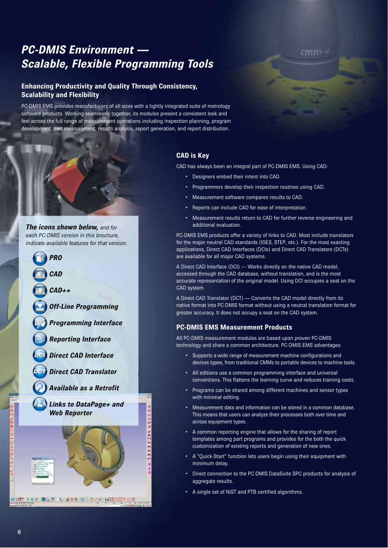
The icons shown below, and for each PC-DMIS version in this brochure, indicate available features for that version.
PRO
CAD
CAD++
Off-Line Programming
Programming Interface
Reporting Interface
Direct CAD Interface
Direct CAD Translator
Available as a Retrofit
Links to DataPage+ and Web Reporter
6
7
Different Levels of Capability to Match Different Requirements
Not all manufacturers make the same types of parts, and not all parts have the same measurement requirements. To meet the varying requirements of a diverse customer base, PC-DMIS EMS offers three configurations of most of its measurement products.
PRO meets the basic needs of companies that do not need to integrate CAD into their measurement processes and do not need to measure contoured parts. PRO is ideal for newcomers to part programming without CAD. It includes features aimed at streamlining the process. These include “guess” modes for automatically identifying the type of features measured and “Quick Start” routines that automate many basic metrology functions. It also offers a rich set of programming, analytical and reporting tools.
CAD is ideal for makers of prismatic parts that want to integrate CAD into their inspection operations. It expands upon the capabilities of PRO by letting customers program and inspect parts using all sorts of CAD models ranging from simple 2D “blueprints” through full 3D solid models. CAD allows full use of all PC-DMIS EMS CAD-linking technologies.
CAD features an intuitive GUI and includes power “wizards” that guide engineers through the programming process. It includes a library of kinematic machine models for simulation and allows users to add new ones if required.
CAD++ lets users measure the most complex parts. It includes all the capabilities of CAD and adds the ability to measure intricate, contoured surfaces including thin-walled sheet metal and plastic, blades, dies and molds. CAD++ supports numerous scanning devices and applications, and it includes algorithms for managing copious amounts of data. Its links to CAD allow users to compare measurement results directly against models for unsurpassed speed and accuracy.
CAD++ is feature rich, yet easy to use. Many years of experience developing metrology software for varied applications in more than 100 industries has refined PC-DMIS products such that programming tools to do even the most difficult jobs are available without burying the user in complexity.
Enhancing Productivity Through Off-Line ProgrammingFor shops where machine time is a valuable commodity, PC-DMIS offers off-line licenses of the CAD and CAD++ configurations. Offline versions allow the inspection machines to be used primarily for measuring parts and not for part programming. An offline license allows users to develop, test and debug inspection routines off-line using CAD models. Simulated program execution is possible on accurate kinematic models of their machines, so programs can be tested before they are ever used on a physical machine.
7
planner
8
Enterprise Metrology Solutions
Linking Design to Inspection
Planning for Inspection
The need for inspection is built into the manufacturing process. However, many organizations have discovered that the process of translating the design intent of a CAD model into a set of inspection instructions for checking a real part isn’t built into anything. The process of communicating intent to inspection can be a difficult and time-consuming informal process with numerous opportunities for misinterpretation and error. PC-DMIS Planner is the solution.
PC-DMIS Planner software is a groundbreaking, stand-alone application that automates the flow of information between the virtual world of the design department and the real world of the engineering departments responsible for part manufacture and quality. PC-DMIS Planner creates a bi-directional link between CAD models and their related inspection programs.
Building Inspection Requirements into CAD Models
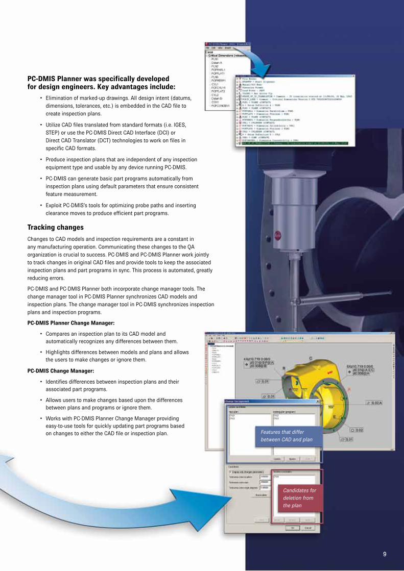
The communication of design requirements and modifications from the design department to the shop floor is often a haphazard proposition. It can include marked-up drawings, endless meetings, numerous phone calls and costly errors. PC-DMIS Planner eliminates these problems by automating the communications process. Information flows electronically from design to quality assurance, keeping all departments in sync. PC-DMIS Planner eliminates one of the last significant disconnects in manufacturing.
Plan and part
program differences
Plan
additions
Candidates for
deletion from the
part program
8
Synchronizing Design and Inspection Using Enterprise Metrology Solutions
Changing part specifications are inevitable. Ensuring that the
latest changes to the CAD model are incorporated into the
inspection programs is the job of PC-DMIS Planner. Planner
directly links the design and inspection groups and tracks
changes across the system, automatically notifying users of
any discrepancies and allowing changes to be made easily.
9
PC-DMIS Planner was specifically developed for design engineers. Key advantages include:
• Elimination of marked-up drawings. All design intent (datums, dimensions, tolerances, etc.) is embedded in the CAD file to create inspection plans.
• Utilize CAD files translated from standard formats (i.e. IGES, STEP) or use the PC-DMIS Direct CAD Interface (DCI) or Direct CAD Translator (DCT) technologies to work on files in specific CAD formats.
• Produce inspection plans that are independent of any inspection equipment type and usable by any device running PC-DMIS.
• PC-DMIS can generate basic part programs automatically from inspection plans using default parameters that ensure consistent feature measurement.
• Exploit PC-DMIS’s tools for optimizing probe paths and inserting clearance moves to produce efficient part programs.
Tracking changes
Changes to CAD models and inspection requirements are a constant in any manufacturing operation. Communicating these changes to the QA organization is crucial to success. PC-DMIS and PC-DMIS Planner work jointly to track changes in original CAD files and provide tools to keep the associated inspection plans and part programs in sync. This process is automated, greatly reducing errors.
PC-DMIS and PC-DMIS Planner both incorporate change manager tools. The change manager tool in PC-DMIS Planner synchronizes CAD models and inspection plans. The change manager tool in PC-DMIS synchronizes inspection plans and inspection programs.
PC-DMIS Planner Change Manager:
• Compares an inspection plan to its CAD model and automatically recognizes any differences between them.
• Highlights differences between models and plans and allows the users to make changes or ignore them.
PC-DMIS Change Manager:
• Identifies differences between inspection plans and their associated part programs.
• Allows users to make changes based upon the differences between plans and programs or ignore them.
• Works with PC-DMIS Planner Change Manager providing easy-to-use tools for quickly updating part programs based on changes to either the CAD file or inspection plan. Features that differ
between CAD and plan
Candidates for
deletion from
the plan
9
cmm
10
Enterprise Metrology Solutions
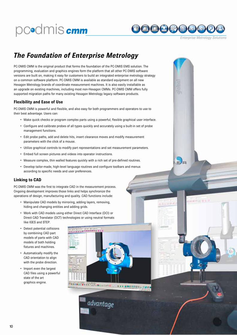
The Foundation of Enterprise MetrologyPC-DMIS CMM is the original product that forms the foundation of the PC-DMIS EMS solution. The programming, evaluation and graphics engines form the platform that all other PC-DMIS software versions are built on, making it easy for customers to build an integrated enterprise metrology strategy on a common software platform. PC-DMIS CMM is available as standard equipment on all new Hexagon Metrology brands of coordinate measurement machines. It is also easily installable as an upgrade on existing machines, including most non-Hexagon CMMs. PC-DMIS CMM offers fully supported migration paths for many existing Hexagon Metrology legacy software products.
Flexibility and Ease of Use
PC-DMIS CMM is powerful and flexible, and also easy for both programmers and operators to use to their best advantage. Users can:
• Make quick checks or program complex parts using a powerful, flexible graphical user interface.
• Configure and calibrate probes of all types quickly and accurately using a built-in set of probe management functions.
• Edit probe paths, add and delete hits, insert clearance moves and modify measurement parameters with the click of a mouse.
• Utilize graphical controls to modify part representations and set measurement parameters.
• Embed full screen pictures and videos into operator instructions.
• Measure complex, thin walled features quickly with a rich set of pre-defined routines.
• Develop tailor-made, high-level language routines and configure toolbars and menus according to specific needs and user preferences.
Linking to CAD
PC-DMIS CMM was the first to integrate CAD in the measurement process. Ongoing development improves those links and helps synchronize the operations of design, manufacturing and quality. CAD functions include:
• Manipulate CAD models by mirroring, adding layers, removing, hiding and changing entities and adding grids.
• Work with CAD models using either Direct CAD Interface (DCI) or Direct CAD Translator (DCT) technologies or using neutral formats like IGES and STEP.
• Detect potential collisions by combining CAD part models of parts with CAD models of both holding fixtures and machines.
• Automatically modify the CAD orientation to align with the probe direction.
• Import even the largest CAD files using a powerful state of the art graphics engine.
10
11
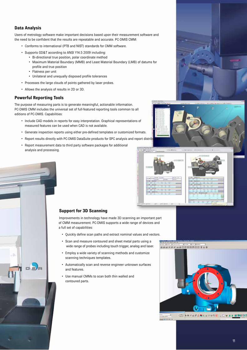
Data Analysis
Users of metrology software make important decisions based upon their measurement software and the need to be confident that the results are repeatable and accurate. PC-DMIS CMM:
• Conforms to international (PTB and NIST) standards for CMM software.
• Supports GD&T according to ANSI Y14.5 2009 including:• Bi-directional true position, polar coordinate method• Maximum Material Boundary (MMB) and Least Material Boundary (LMB) of datums for
profile and true position• Flatness per unit• Unilateral and unequally disposed profile tolerances
• Processes the large clouds of points gathered by laser probes.
• Allows the analysis of results in 2D or 3D.
Powerful Reporting Tools
The purpose of measuring parts is to generate meaningful, actionable information. PC-DMIS CMM includes the universal set of full-featured reporting tools common to all editions of PC-DMIS. Capabilities:
• Include CAD models in reports for easy interpretation. Graphical representations of measured features can be used when CAD is not available.
• Generate inspection reports using either pre-defined templates or customized formats.
• Report results directly with PC-DMIS DataSuite products for SPC analysis and report distribution.
• Report measurement data to third party software packages for additional analysis and processing.
Support for 3D Scanning
Improvements in technology have made 3D scanning an important part of CMM measurement. PC-DMIS supports a wide range of devices and a full set of capabilities:
• Quickly define scan paths and extract nominal values and vectors.
• Scan and measure contoured and sheet metal parts using a wide range of probes including touch trigger, analog and laser.
• Employ a wide variety of scanning methods and customize scanning techniques templates.
• Automatically scan and reverse engineer unknown surfaces and features.
• Use manual CMMs to scan both thin walled and contoured parts.
11

12
Enterprise Metrology Solutions
vision
A New Take on Vision Metrology
Bringing the Power of PC-DMIS to Vision Measurement
PC-DMIS has long set the standard for CAD-based CMM software. PC-DMIS Vision
brings these capabilities and a host of new ones to the world of vision measurement.
PC-DMIS Vision provides vision metrologists with the same tools long available to
users of PC-DMIS CMM. These include powerful methods for measuring 3D parts
on vision systems. It also makes short work of measuring 2D parts, the traditional
applications of vision measurement. In addition, PC-DMIS Vision users have access
to the complete PC-DMIS EMS range of additional analytical and reporting
capabilities.
Putting CAD in Vision Measurement
PC-DMIS pioneered the incorporation of CAD into metrology software. PC-DMIS
Vision adapts this fundamental capability to the unique demands of vision metrology.
Allowing CAD models to be used as perfect “master parts” for programming and
inspection purposes greatly improves both programming and inspection throughput.
Benefits of PC-DMIS Vision’s CAD-based capabilities:
• Perform both part-to-CAD and advanced GD&T analyses not possible with
traditional vision software.
• Extract information right from the CAD model, eliminating errors of data
interpretation and input.
• Increase part programming throughput up to 75% by using 3D CAD models to
develop, check and edit inspection routines with point-and-click simplicity.
• Import CAD models and export measurement results in a wide range of
industry standard and vendor specific formats.
• Develop programs off-line with an optional module that simulates all
aspects of the measurement process. Switch between the CAD view and a
CADCamera© view (shown opposite, bottom) that accurately simulates not
only a camera image but also the illumination and magnification parameters.
• Draw on PC-DMIS’s feature based programming functions to simplify both
feature creation and editing.
• Standard PC-DMIS reporting toolset allows CAD images to be embedded in
inspection reports for ease of reference.
12
13
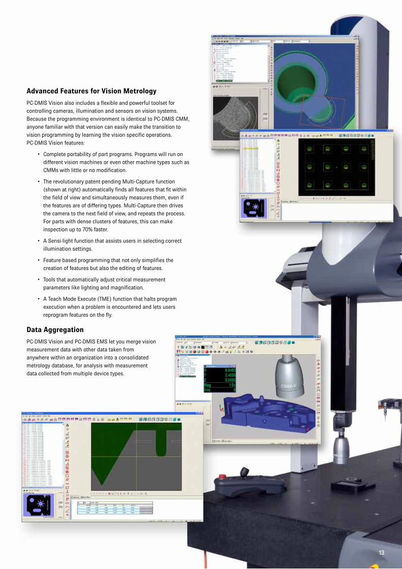
Advanced Features for Vision Metrology
PC-DMIS Vision also includes a flexible and powerful toolset for
controlling cameras, illumination and sensors on vision systems.
Because the programming environment is identical to PC-DMIS CMM,
anyone familiar with that version can easily make the transition to
vision programming by learning the vision specific operations.
PC-DMIS Vision features:
• Complete portability of part programs. Programs will run on
different vision machines or even other machine types such as
CMMs with little or no modification.
• The revolutionary patent-pending Multi-Capture function
(shown at right) automatically finds all features that fit within
the field of view and simultaneously measures them, even if
the features are of differing types. Multi-Capture then drives
the camera to the next field of view, and repeats the process.
For parts with dense clusters of features, this can make
inspection up to 70% faster.
• A Sensi-light function that assists users in selecting correct
illumination settings.
• Feature based programming that not only simplifies the
creation of features but also the editing of features.
• Tools that automatically adjust critical measurement
parameters like lighting and magnification.
• A Teach Mode Execute (TME) function that halts program
execution when a problem is encountered and lets users
reprogram features on the fly.
Data Aggregation
PC-DMIS Vision and PC-DMIS EMS let you merge vision
measurement data with other data taken from
anywhere within an organization into a consolidated
metrology database, for analysis with measurement
data collected from multiple device types.
13
portable
14
Enterprise Metrology Solutions
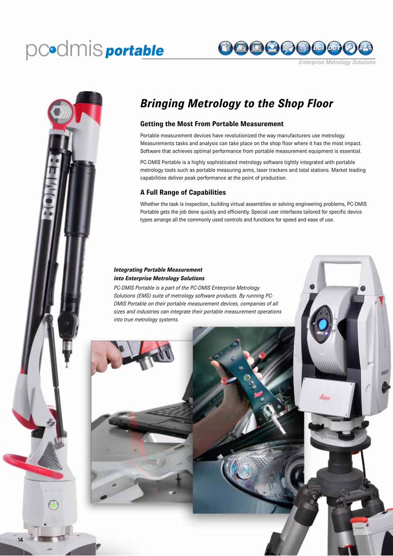
Bringing Metrology to the Shop Floor
Getting the Most From Portable Measurement
Portable measurement devices have revolutionized the way manufacturers use metrology.
Measurements tasks and analysis can take place on the shop floor where it has the most impact.
Software that achieves optimal performance from portable measurement equipment is essential.
PC-DMIS Portable is a highly sophisticated metrology software tightly integrated with portable
metrology tools such as portable measuring arms, laser trackers and total stations. Market leading
capabilities deliver peak performance at the point of production.
A Full Range of Capabilities
Whether the task is inspection, building virtual assemblies or solving engineering problems, PC-DMIS
Portable gets the job done quickly and efficiently. Special user interfaces tailored for specific device
types arrange all the commonly used controls and functions for speed and ease of use.
Integrating Portable Measurement
into Enterprise Metrology Solutions
PC-DMIS Portable is a part of the PC-DMIS Enterprise Metrology
Solutions (EMS) suite of metrology software products. By running PC-
DMIS Portable on their portable measurement devices, companies of all
sizes and industries can integrate their portable measurement operations
into true metrology systems.
14
15
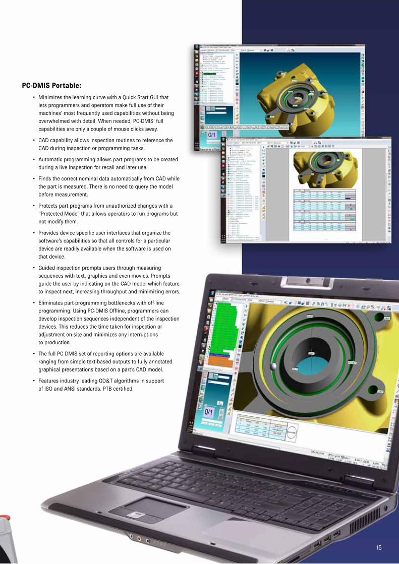
PC-DMIS Portable:
• Minimizes the learning curve with a Quick Start GUI that
lets programmers and operators make full use of their
machines’ most frequently used capabilities without being
overwhelmed with detail. When needed, PC-DMIS’ full
capabilities are only a couple of mouse clicks away.
• CAD capability allows inspection routines to reference the
CAD during inspection or programming tasks.
• Automatic programming allows part programs to be created
during a live inspection for recall and later use.
• Finds the correct nominal data automatically from CAD while
the part is measured. There is no need to query the model
before measurement.
• Protects part programs from unauthorized changes with a
“Protected Mode” that allows operators to run programs but
not modify them.
• Provides device specific user interfaces that organize the
software’s capabilities so that all controls for a particular
device are readily available when the software is used on
that device.
• Guided inspection prompts users through measuring
sequences with text, graphics and even movies. Prompts
guide the user by indicating on the CAD model which feature
to inspect next, increasing throughput and minimizing errors.
• Eliminates part-programming bottlenecks with off-line
programming. Using PC-DMIS Offline, programmers can
develop inspection sequences independent of the inspection
devices. This reduces the time taken for inspection or
adjustment on-site and minimizes any interruptions
to production.
• The full PC-DMIS set of reporting options are available
ranging from simple text-based outputs to fully annotated
graphical presentations based on a part’s CAD model.
• Features industry leading GD&T algorithms in support
of ISO and ANSI standards. PTB certified.
15
16
Enterprise Metrology Solutions
nc
16
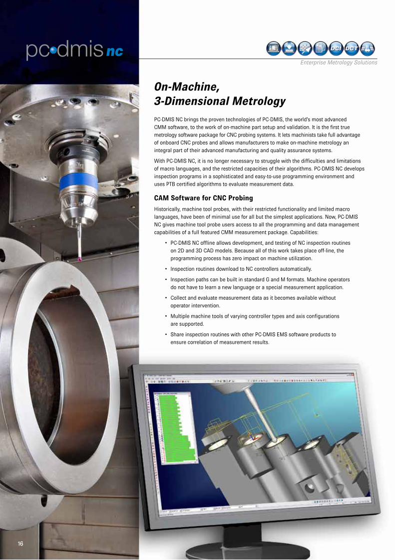
PC-DMIS NC brings the proven technologies of PC-DMIS, the world’s most advanced CMM software, to the work of on-machine part setup and validation. It is the first true metrology software package for CNC probing systems. It lets machinists take full advantage of onboard CNC probes and allows manufacturers to make on-machine metrology an integral part of their advanced manufacturing and quality assurance systems.
With PC-DMIS NC, it is no longer necessary to struggle with the difficulties and limitations of macro languages, and the restricted capacities of their algorithms. PC-DMIS NC develops inspection programs in a sophisticated and easy-to-use programming environment and uses PTB certified algorithms to evaluate measurement data.
CAM Software for CNC Probing
Historically, machine tool probes, with their restricted functionality and limited macro languages, have been of minimal use for all but the simplest applications. Now, PC-DMIS NC gives machine tool probe users access to all the programming and data management capabilities of a full featured CMM measurement package. Capabilities:
• PC-DMIS NC offline allows development, and testing of NC inspection routines on 2D and 3D CAD models. Because all of this work takes place off-line, the programming process has zero impact on machine utilization.
• Inspection routines download to NC controllers automatically.
• Inspection paths can be built in standard G and M formats. Machine operators do not have to learn a new language or a special measurement application.
• Collect and evaluate measurement data as it becomes available without operator intervention.
• Multiple machine tools of varying controller types and axis configurations are supported.
• Share inspection routines with other PC-DMIS EMS software products to ensure correlation of measurement results.
On-Machine, 3-Dimensional Metrology
1717
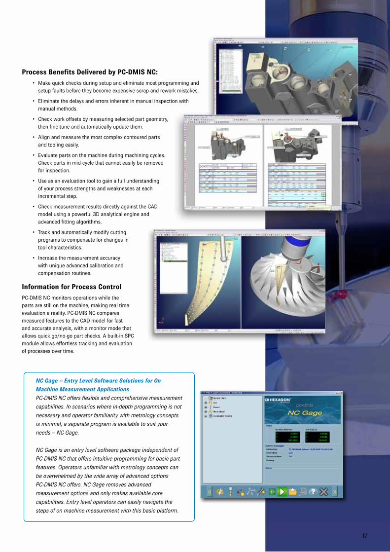
Process Benefits Delivered by PC-DMIS NC:
• Make quick checks during setup and eliminate most programming and setup faults before they become expensive scrap and rework mistakes.
• Eliminate the delays and errors inherent in manual inspection with manual methods.
• Check work offsets by measuring selected part geometry, then fine tune and automatically update them.
• Align and measure the most complex contoured parts and tooling easily.
• Evaluate parts on the machine during machining cycles. Check parts in mid-cycle that cannot easily be removed for inspection.
• Use as an evaluation tool to gain a full understanding of your process strengths and weaknesses at each incremental step.
• Check measurement results directly against the CAD model using a powerful 3D analytical engine and advanced fitting algorithms.
• Track and automatically modify cutting programs to compensate for changes in tool characteristics.
• Increase the measurement accuracy with unique advanced calibration and compensation routines.
Information for Process Control
PC-DMIS NC monitors operations while the parts are still on the machine, making real time evaluation a reality. PC-DMIS NC compares measured features to the CAD model for fast and accurate analysis, with a monitor mode that allows quick go/no-go part checks. A built-in SPC module allows effortless tracking and evaluation of processes over time.
NC Gage – Entry Level Software Solutions for On
Machine Measurement Applications
PC-DMIS NC offers flexible and comprehensive measurement
capabilities. In scenarios where in-depth programming is not
necessary and operator familiarity with metrology concepts
is minimal, a separate program is available to suit your
needs – NC Gage.
NC Gage is an entry level software package independent of
PC-DMIS NC that offers intuitive programming for basic part
features. Operators unfamiliar with metrology concepts can
be overwhelmed by the wide array of advanced options
PC-DMIS NC offers. NC Gage removes advanced
measurement options and only makes available core
capabilities. Entry level operators can easily navigate the
steps of on machine measurement with this basic platform.
1818
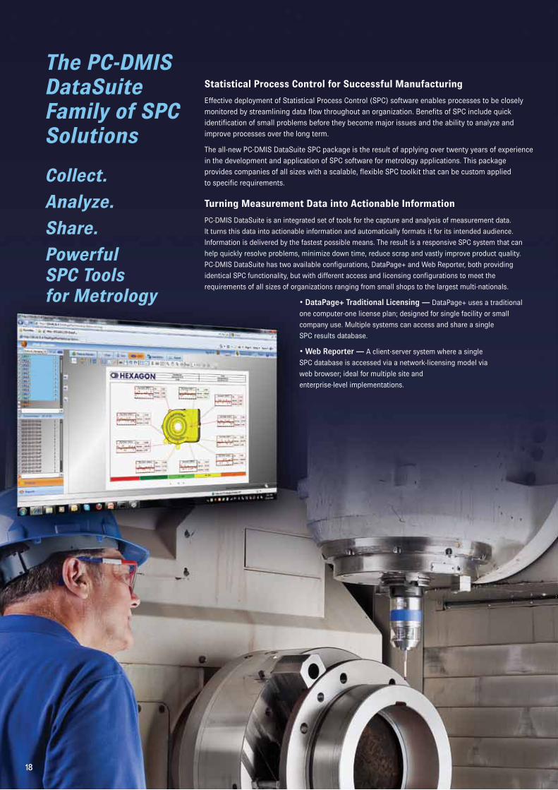
The PC-DMIS DataSuite Family of SPC Solutions
Collect.
Analyze.
Share.
Powerful SPC Tools for Metrology
Statistical Process Control for Successful Manufacturing
Effective deployment of Statistical Process Control (SPC) software enables processes to be closely
monitored by streamlining data flow throughout an organization. Benefits of SPC include quick
identification of small problems before they become major issues and the ability to analyze and
improve processes over the long term.
The all-new PC-DMIS DataSuite SPC package is the result of applying over twenty years of experience
in the development and application of SPC software for metrology applications. This package
provides companies of all sizes with a scalable, flexible SPC toolkit that can be custom applied
to specific requirements.
Turning Measurement Data into Actionable Information
PC-DMIS DataSuite is an integrated set of tools for the capture and analysis of measurement data.
It turns this data into actionable information and automatically formats it for its intended audience.
Information is delivered by the fastest possible means. The result is a responsive SPC system that can
help quickly resolve problems, minimize down time, reduce scrap and vastly improve product quality.
PC-DMIS DataSuite has two available configurations, DataPage+ and Web Reporter, both providing
identical SPC functionality, but with different access and licensing configurations to meet the
requirements of all sizes of organizations ranging from small shops to the largest multi-nationals.
• DataPage+ Traditional Licensing — DataPage+ uses a traditional
one computer-one license plan; designed for single facility or small
company use. Multiple systems can access and share a single
SPC results database.
• Web Reporter — A client-server system where a single
SPC database is accessed via a network-licensing model via
web browser; ideal for multiple site and
enterprise-level implementations.
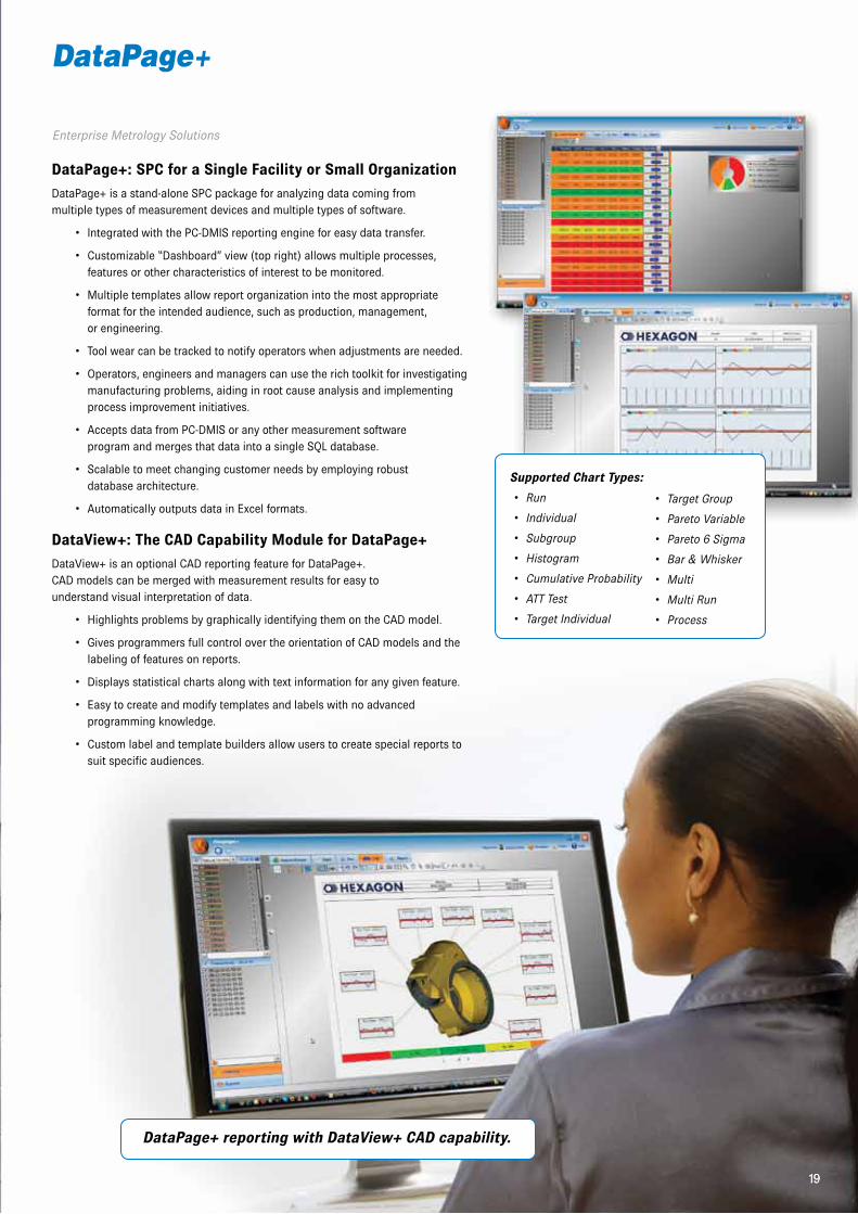
DataPage+
19
DataPage+: SPC for a Single Facility or Small Organization
DataPage+ is a stand-alone SPC package for analyzing data coming from multiple types of measurement devices and multiple types of software.
• Integrated with the PC-DMIS reporting engine for easy data transfer.
• Customizable “Dashboard” view (top right) allows multiple processes, features or other characteristics of interest to be monitored.
• Multiple templates allow report organization into the most appropriate format for the intended audience, such as production, management, or engineering.
• Tool wear can be tracked to notify operators when adjustments are needed.
• Operators, engineers and managers can use the rich toolkit for investigating manufacturing problems, aiding in root cause analysis and implementing process improvement initiatives.
• Accepts data from PC-DMIS or any other measurement software program and merges that data into a single SQL database.
• Scalable to meet changing customer needs by employing robust database architecture.
• Automatically outputs data in Excel formats.
DataView+: The CAD Capability Module for DataPage+
DataView+ is an optional CAD reporting feature for DataPage+. CAD models can be merged with measurement results for easy to understand visual interpretation of data.
• Highlights problems by graphically identifying them on the CAD model.
• Gives programmers full control over the orientation of CAD models and the labeling of features on reports.
• Displays statistical charts along with text information for any given feature.
• Easy to create and modify templates and labels with no advanced programming knowledge.
• Custom label and template builders allow users to create special reports to suit specific audiences.
19
DataPage+ reporting with DataView+ CAD capability.
Supported Chart Types:
• Run
• Individual
• Subgroup
•Histogram
• CumulativeProbability
• ATTTest
• TargetIndividual
• TargetGroup
• ParetoVariable
• Pareto6Sigma
• Bar&Whisker
• Multi
• MultiRun
• Process
Enterprise Metrology Solutions
20
Web Reporter
Using Internet Technology to Build Enterprise Quality Reporting Systems
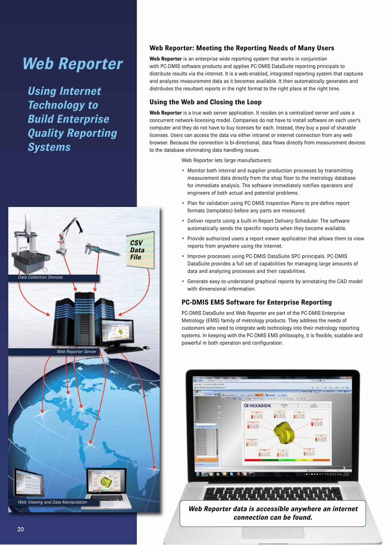
Web Reporter: Meeting the Reporting Needs of Many Users
Web Reporter is an enterprise wide reporting system that works in conjunction with PC-DMIS software products and applies PC-DMIS DataSuite reporting principals to distribute results via the internet. It is a web-enabled, integrated reporting system that captures and analyzes measurement data as it becomes available. It then automatically generates and distributes the resultant reports in the right format to the right place at the right time.
Using the Web and Closing the Loop
Web Reporter is a true web server application. It resides on a centralized server and uses a concurrent network-licensing model. Companies do not have to install software on each user’s computer and they do not have to buy licenses for each. Instead, they buy a pool of sharable licenses. Users can access the data via either intranet or internet connection from any web browser. Because the connection is bi-directional, data flows directly from measurement devices to the database eliminating data handling issues.
Web Reporter lets large manufacturers:
• Monitor both internal and supplier production processes by transmitting measurement data directly from the shop floor to the metrology database for immediate analysis. The software immediately notifies operators and engineers of both actual and potential problems.
• Plan for validation using PC-DMIS Inspection Plans to pre-define report formats (templates) before any parts are measured.
• Deliver reports using a built-in Report Delivery Scheduler. The software automatically sends the specific reports when they become available.
• Provide authorized users a report viewer application that allows them to view reports from anywhere using the internet.
• Improve processes using PC-DMIS DataSuite SPC principals. PC-DMIS DataSuite provides a full set of capabilities for managing large amounts of data and analyzing processes and their capabilities.
• Generate easy-to-understand graphical reports by annotating the CAD model with dimensional information.
PC-DMIS EMS Software for Enterprise Reporting
PC-DMIS DataSuite and Web Reporter are part of the PC-DMIS Enterprise Metrology (EMS) family of metrology products. They address the needs of customers who need to integrate web technology into their metrology reporting systems. In keeping with the PC-DMIS EMS philosophy, it is flexible, scalable and powerful in both operation and configuration.
20
Web Reporter data is accessible anywhere an internet connection can be found.
WebViewingandDataManipulation
WebReporterServer
Data Collection Devices
CSV Data File
reshaper
21
Enterprise Metrology Solutions
Software for Point Cloud Analysis
21
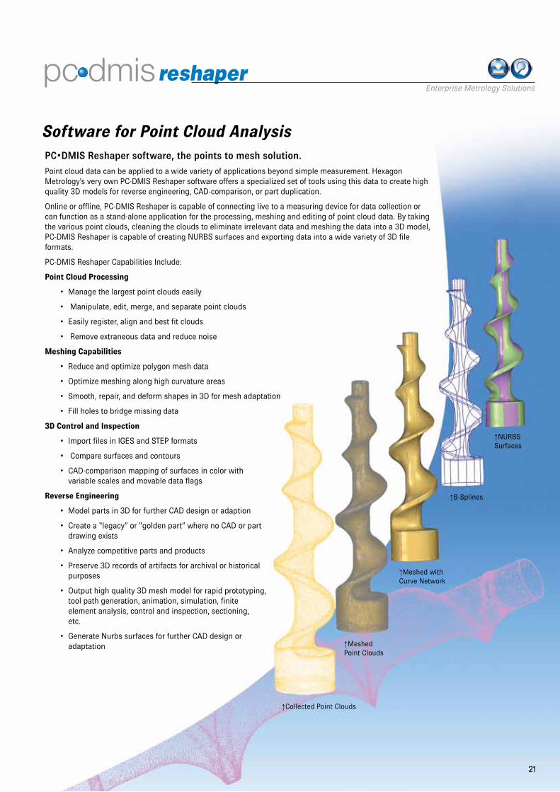
PC•DMIS Reshaper software, the points to mesh solution.
Point cloud data can be applied to a wide variety of applications beyond simple measurement. Hexagon Metrology’s very own PC-DMIS Reshaper software offers a specialized set of tools using this data to create high quality 3D models for reverse engineering, CAD-comparison, or part duplication.
Online or offline, PC-DMIS Reshaper is capable of connecting live to a measuring device for data collection or can function as a stand-alone application for the processing, meshing and editing of point cloud data. By taking the various point clouds, cleaning the clouds to eliminate irrelevant data and meshing the data into a 3D model, PC-DMIS Reshaper is capable of creating NURBS surfaces and exporting data into a wide variety of 3D file formats.
PC-DMIS Reshaper Capabilities Include:
Point Cloud Processing
• Manage the largest point clouds easily
• Manipulate, edit, merge, and separate point clouds
• Easily register, align and best fit clouds
• Remove extraneous data and reduce noise
Meshing Capabilities
• Reduce and optimize polygon mesh data
• Optimize meshing along high curvature areas
• Smooth, repair, and deform shapes in 3D for mesh adaptation
• Fill holes to bridge missing data
3D Control and Inspection
• Import files in IGES and STEP formats
• Compare surfaces and contours
• CAD-comparison mapping of surfaces in color with variable scales and movable data flags
Reverse Engineering
• Model parts in 3D for further CAD design or adaption
• Create a “legacy” or “golden part” where no CAD or part drawing exists
• Analyze competitive parts and products
• Preserve 3D records of artifacts for archival or historical purposes
• Output high quality 3D mesh model for rapid prototyping, tool path generation, animation, simulation, finite element analysis, control and inspection, sectioning, etc.
• Generate Nurbs surfaces for further CAD design or adaptation
↑Collected Point Clouds
↑Meshed Point Clouds
↑Meshed with Curve Network
↑B-Splines
↑NURBS Surfaces
22
PC-DMIS EMS ExtensionsSoftware Tools for Special Applications
PC-DMIS EMS offers a range of extensions to the basic PC-DMIS configurations. These can either be stand-alone variations of the core product or add-ons that either control a specialized hardware device such as a rotary table or perform a particular task or group of tasks.
Stand-alone variations make it easy to check parts such as blades and gears or simplify overall software operation for specific environments. These include:
PC-DMIS Gear – Simplifying a Difficult Job
PC-DMIS Gear makes the tough job of gear measurement easy. Features:
• Build part programs by completing an easy-to-understand, rules driven form.
• Measure gears according to a diverse set of international standards including: AGMA 2000-A88, DIN 3962, JIS B 1702 and ISO 1328.
• Align gears and setup and calibrate probe easily using a combination of wizards and predefined routines.
• Generate reports using a full set of industry standard output templates.
PC-DMIS Blade – Software for Blade Measurement and Analysis
PC-DMIS Blade is a turnkey solution for measuring and analyzing blades. PC-DMIS Blade:
• Features a simple to use GUI that lets users identify parts, select sections and initiate scans with minimal effort.
• Accurately simulates traditional, section-based (guillotine) gages at a fraction of the cost.
• Measures characteristics like contour and twist quickly without compromising accuracy.
• Aligns parts quickly using traditional methods like root holding with XYZ offsets and angle rotation to the stacking axis. Also, supports iterative alignments using CAD surfaces or 6-points rest.
PC-DMIS STI+ Brings Automated Metrology to the Shop Floor
PC-DMIS STI+ lets shop floor personnel check parts without becoming measurement experts by guiding them through part setup and measurement. PC-DMIS STI+:
• Makes the CMM an attractive alternative to functional shop floor gauging by allowing users to run pre-programmed inspections and review reports without any direct interaction with the underlying PC-DMIS software.
• Lets shop floor personnel select inspection programs by picking them from a graphical or alphanumeric list.
• Guides operators through part alignment and fixturing using pictures of the part and fixture.
• Automatically runs the inspection routines and generates graphical reports showing features of interest, including “good part “ and “bad part” flags.
• Keeps a history of all parts inspected.
• Turns the CMM into a measurement device that is as simple to use as a go/no go dedicated gage with the flexibility and analytical capabilities of a sophisticated measurement machine.
Options for Productivity
Options allow users to configure PC-DMIS EMS products to meet specific requirements. Supporting special devices, machine configurations, or higher level capabilities, options include:
• Rotary Tables – Control a variety of indexable or infinitely variable rotary tables. Built-in routines simplify table calibration and programming.
• Tool and Tip Changers – Use any of the most popular tool and tip changers with any PC-DMIS package. This module can manage multiple changers on a single machine and provides easy-to-use utilities for changer and probe calibration.
• Supports ISO DMIS input and output allowing the software to both run and export programs in DMIS format and generate results in accordance with the specification.
22
23
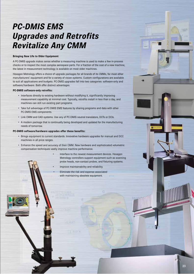
PC-DMIS EMS Upgrades and RetrofitsRevitalize Any CMMBringing New Life to Older Equipment
A PC-DMIS upgrade makes sense whether a measuring machine is used to make a few in-process checks or to inspect the most complex aerospace parts. For a fraction of the cost of a new machine, the latest in measurement technology is available on most older machines.
Hexagon Metrology offers a choice of upgrade packages for all brands of its CMMs, for most other manufacturers’ equipment and for a variety of vision systems. Custom configurations are available to suit all applications and budgets. PC-DMIS upgrades fall into two categories: software-only and software/hardware. Both offer distinct advantages.
PC-DMIS software-only retrofits:
• Interfaces directly to existing hardware without modifying it, significantly improving measurement capability at minimal cost. Typically, retrofits install in less than a day, and machines can still run existing part programs.
• Take full advantage of PC-DMIS EMS features by sharing programs and data with other PC-DMIS EMS components.
• Link CMM and CAD systems. Use any of PC-DMIS neutral translators, DCTs or DCIs.
• A modern package that is continually being developed and updated for the manufacturing needs of tomorrow.
PC-DMIS software/hardware upgrades offer these benefits:
• Brings equipment to current standards. Innovative hardware upgrades for manual and DCC machines in all price ranges.
• Enhance the speed and accuracy of their CMM. New hardware and sophisticated volumetric compensation techniques vastly improve machine performance.
• Interface to the newest measurement devices. Hexagon Metrology controllers support equipment such as scanning probe heads, non-contact probes, and fixturing systems.
• Improve maintainability and reliability.
• Eliminate the risk and expense associated with maintaining obsolete equipment.
23
PC-DMIS Enterprise Metrology Systems (EMS)
The origins of the PC-DMIS EMS philosophy began more
than twenty years ago with a simple concept: parts
designed in CAD systems ought to be inspected to the
original CAD models, and the reality of inspecting to CAD
on a CMM was born.
Today, PC-DMIS Enterprise Metrology Solutions (EMS)
encompasses multiple interconnected software packages
that assist with dimensional quality control at every stage
from design through production. PC-DMIS EMS goes
far beyond its origin to include tools for many types of
metrology hardware platforms, statistical process control,
and change management. Manufacturers can maintain
complete control over dimensional metrology throughout
the manufacturing process with a single solution. With
PC-DMIS EMS products, manufacturers of all sizes and
disciplines can build metrology systems tailored to meet
their specific requirements. PC-DMIS EMS turns data about
manufacturing processes into actionable information.
PC-DMIS is the most popular dimensional metrology
software worldwide, with tens of thousands of copies in
use.
Wilcox Associates Inc., the developer of PC-DMIS EMS, is
the primary software development group within Hexagon
Metrology, the largest provider of dimensional metrology
products, software and services worldwide.
Hexagon Metrology
Hexagon Metrology is part of the Hexagon AB Group and
includes leading metrology brands such as Brown &
Sharpe, CogniTens, DEA, Leica Geosystems (Metrology
Division), Leitz, m&h Inprocess Messtechnik, Optiv, PC-
DMIS, QUINDOS, ROMER and TESA.
www.pcdmis.com
www.hexagonmetrology.com
© Hexagon Metrology. Part of Hexagon Group
All rights reserved. Features and specifications in this brochure
may change without notice.
Printed in Germany. November 2010
7851
98


![Eng Metrology Topic 4 [Noncontact Inspection]](https://static.fdocuments.in/doc/165x107/563db9b3550346aa9a9f1d40/eng-metrology-topic-4-noncontact-inspection.jpg)