PC Chapter 6 Diffraction - Santa Monica...
50
Chapter 36 Diffraction Dr. Armen Kocharian
Transcript of PC Chapter 6 Diffraction - Santa Monica...

Chapter 36
Diffraction
Dr. Armen Kocharian
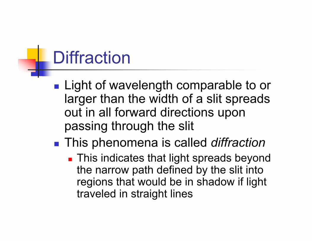
DiffractionLight of wavelength comparable to or larger than the width of a slit spreads out in all forward directions upon passing through the slitThis phenomena is called diffraction
This indicates that light spreads beyond the narrow path defined by the slit into regions that would be in shadow if light traveled in straight lines
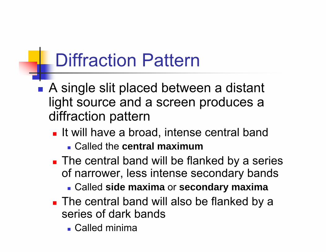
Diffraction PatternA single slit placed between a distant light source and a screen produces a diffraction pattern
It will have a broad, intense central bandCalled the central maximum
The central band will be flanked by a series of narrower, less intense secondary bands
Called side maxima or secondary maximaThe central band will also be flanked by a series of dark bands
Called minima
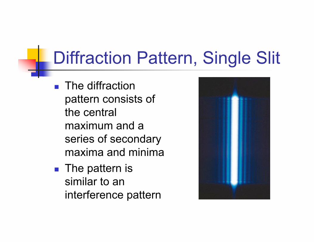
Diffraction Pattern, Single SlitThe diffraction pattern consists of the central maximum and a series of secondary maxima and minimaThe pattern is similar to an interference pattern
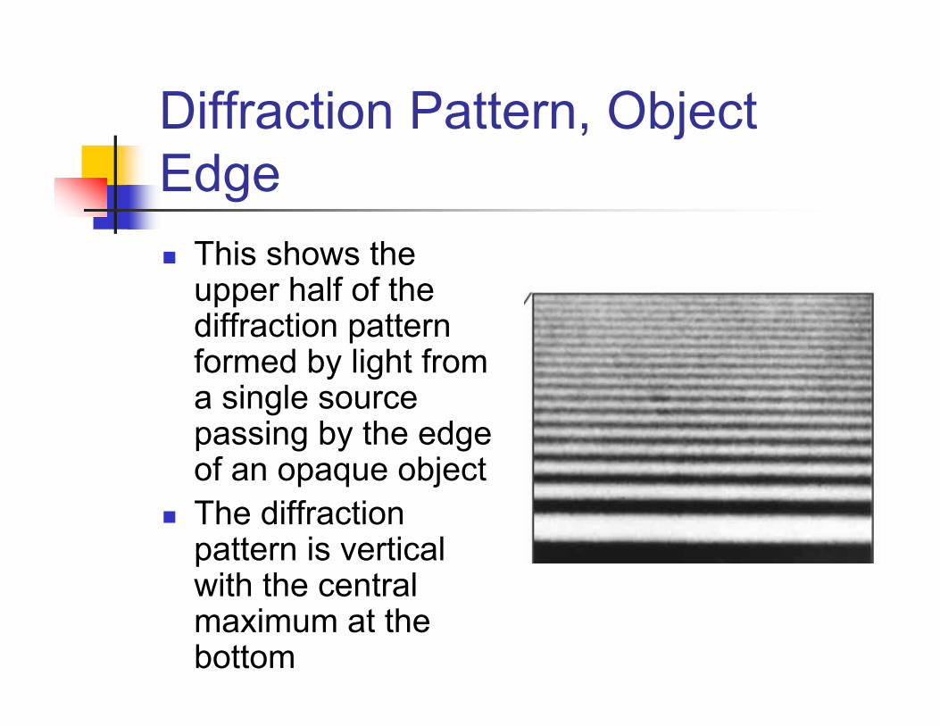
Diffraction Pattern, Object Edge
This shows the upper half of the diffraction pattern formed by light from a single source passing by the edge of an opaque objectThe diffraction pattern is vertical with the central maximum at the bottom

Fraunhofer Diffraction PatternA Fraunhoferdiffraction patternoccurs when the rays leave the diffracting object in parallel directions
Screen very far from the slitCould be accomplished by a converging lens

Fraunhofer Diffraction Pattern Photo
A bright fringe is seen along the axis (θ = 0) Alternating bright and dark fringes are seen on each side
Diffraction vs. Diffraction Pattern
Diffraction refers to the general behavior of waves spreading out as they pass through a slitA diffraction pattern is actually a misnomer that is deeply entrenched
The pattern seen on the screen is actually another interference patternThe interference is between parts of the incident light illuminating different regions of the slit

Single-Slit DiffractionThe finite width of slits is the basis for understanding Fraunhofer diffractionAccording to Huygens’s principle, each portion of the slit acts as a source of light wavesTherefore, light from one portion of the slit can interfere with light from another portion

Single-Slit Diffraction, 2The resultant light intensity on a viewing screen depends on the direction θThe diffraction pattern is actually an interference pattern
The different sources of light are different portions of the single slit

Single-Slit Diffraction, AnalysisAll the waves that originate at the slit are in phaseWave 1 travels farther than wave 3 by an amount equal to the path difference
(a/2) sin θIf this path difference is exactly half of a wavelength, the two waves cancel each other and destructive interference resultsIn general, destructive interference occurs for a single slit of width a when sin θdark = mλ / a
m = ±1, ±2, ±3, …
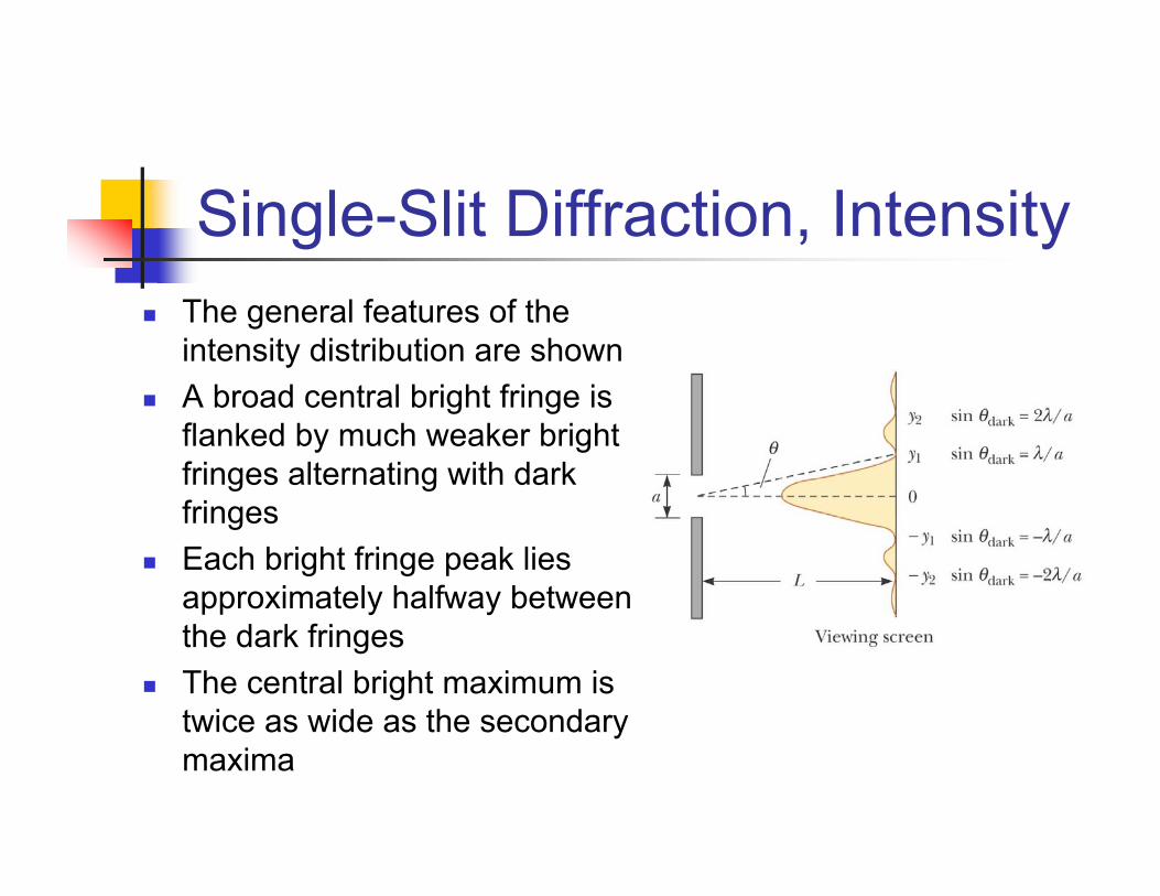
Single-Slit Diffraction, IntensityThe general features of the intensity distribution are shownA broad central bright fringe is flanked by much weaker bright fringes alternating with dark fringesEach bright fringe peak lies approximately halfway between the dark fringesThe central bright maximum is twice as wide as the secondary maxima

Intensity of Single-Slit Diffraction Patterns
Phasors can be used to determine the light intensity distribution for a single-slit diffraction patternSlit width a can be thought of as being divided into zones
The zones have a width of Δy
Each zone acts as a source of coherent radiation
Intensity of Single-Slit Diffraction Patterns, 2
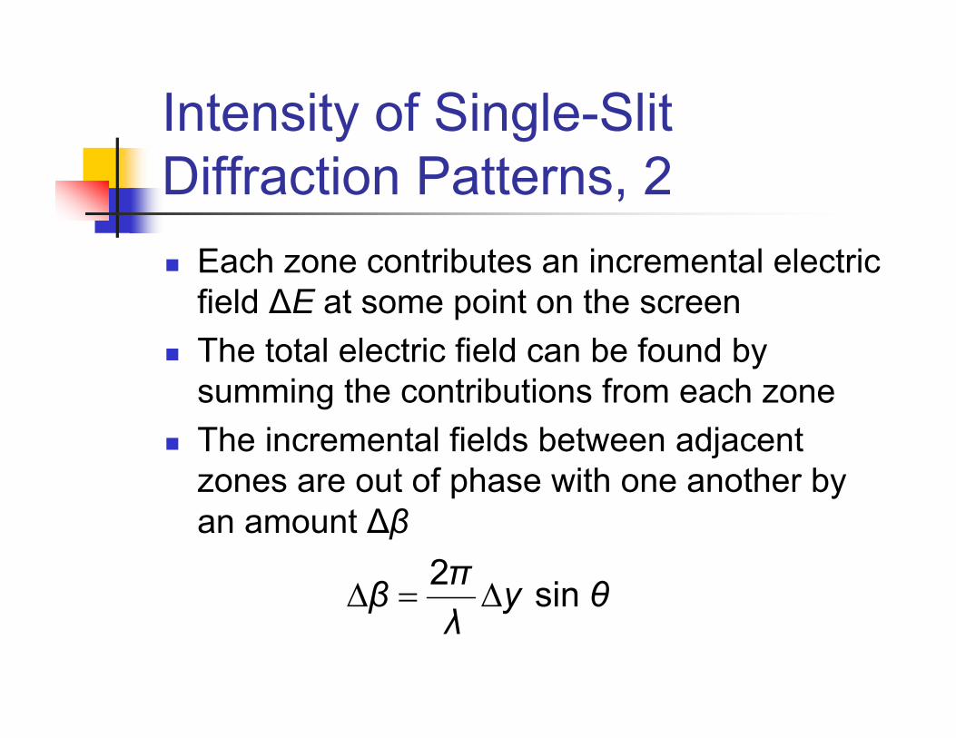
Each zone contributes an incremental electric field ΔE at some point on the screenThe total electric field can be found by summing the contributions from each zoneThe incremental fields between adjacent zones are out of phase with one another by an amount Δβ
2 sin πβ y θλ
Δ = Δ

Phasor for ER, θ = 0
θ = 0 and all phasors are alignedThe field at the center is Eo = N ΔE
N is the number of zonesER is a maximum
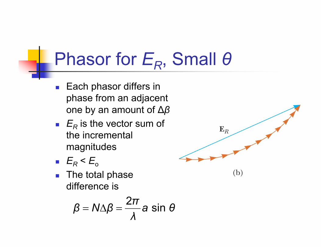
Phasor for ER, Small θEach phasor differs in phase from an adjacent one by an amount of ΔβER is the vector sum of the incremental magnitudesER < Eo
The total phase difference is
2 sin πβ N β a θλ
= Δ =

Phasor for ER, θ = 2πAs θ increases, the chain of phasors eventually forms a closed pathThe vector sum is zero, so ER =0This corresponds to a minimum on the screen
ER When θ = 2π, cont.At this point, β = N Δβ = 2πTherefore, sin θdark = λ / a
Remember, a = N Δy is the width of the slitThis is the first minimum
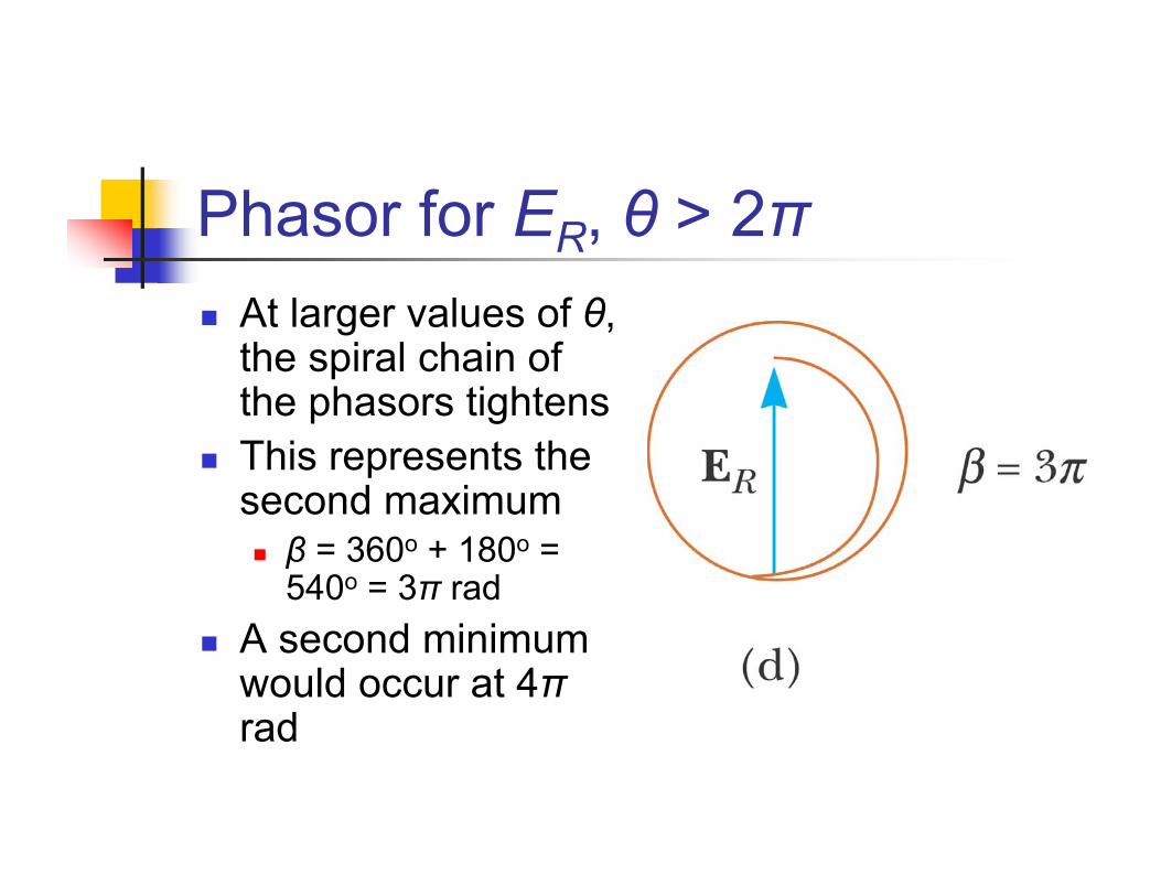
Phasor for ER, θ > 2πAt larger values of θ, the spiral chain of the phasors tightensThis represents the second maximum
β = 360o + 180o = 540o = 3π rad
A second minimum would occur at 4πrad

Resultant E, GeneralConsider the limiting condition of Δybecoming infinitesimal (dy) and N → ∞The phasor chains become the red curveEo = arc lengthER = chord lengthThis also shows that
2sin2
Rβ ER
=

IntensityThe light intensity at a point on the screen is proportional to the square of ER:
Imax is the intensity at θ = 0This is the central maximum
( ) 2
maxsin 2
2I I
ββ
⎡ ⎤= ⎢ ⎥
⎣ ⎦

Intensity, cont.The intensity can also be expressed as
Minima occur at
( ) 2
maxsin sin
sin I I
πa θ λπa θ λ
⎡ ⎤= ⎢ ⎥
⎣ ⎦
darkdark
sin or sin πa θ λmπ θ mλ a
= =

Intensity, finalMost of the light intensity is concentrated in the central maximumThe graph shows a plot of light intensity vs. β/2
Intensity of Two-Slit Diffraction Patterns
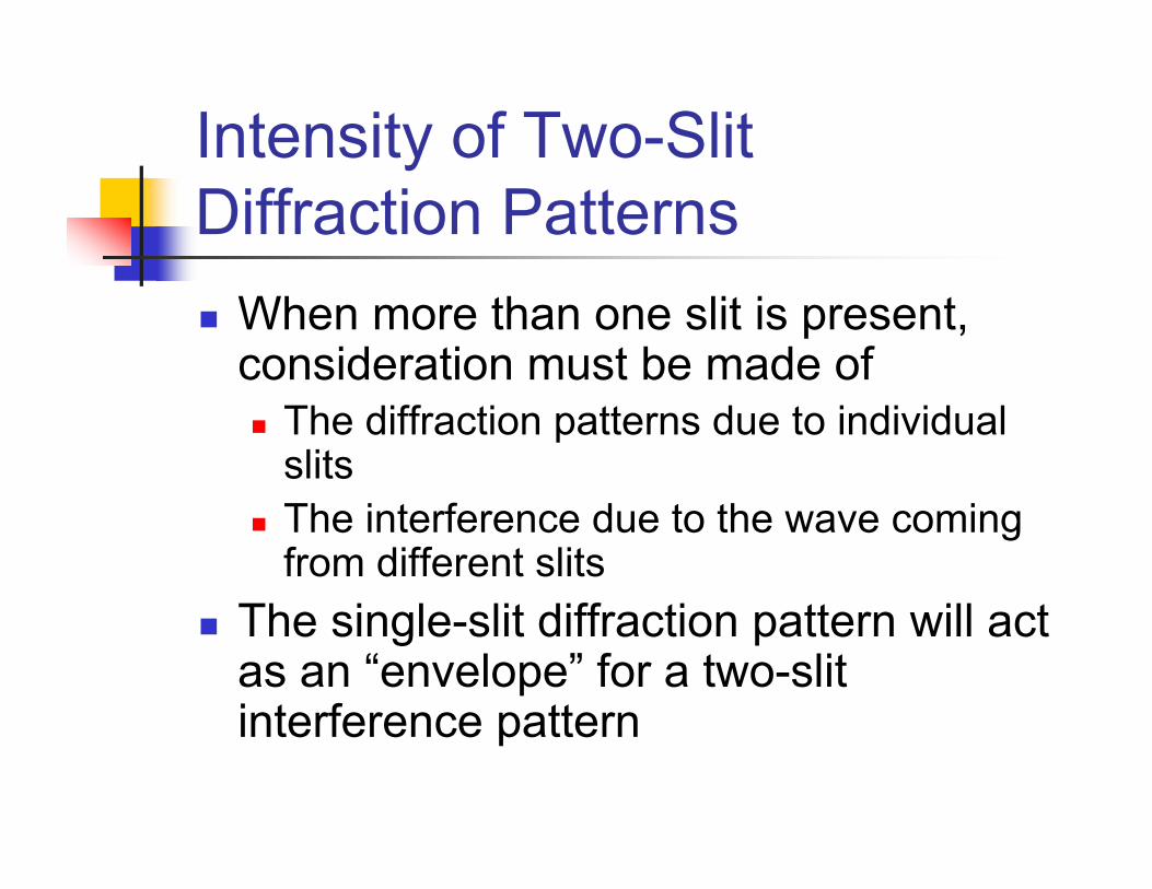
When more than one slit is present, consideration must be made of
The diffraction patterns due to individual slitsThe interference due to the wave coming from different slits
The single-slit diffraction pattern will act as an “envelope” for a two-slit interference pattern

Intensity of Two-Slit Diffraction Patterns, Equation
To determine the maximum intensity:
The factor in the square brackets represents the single-slit diffraction pattern
This acts as the envelopeThe two-slit interference term is the cos2
term
( ) 22
maxsin sin sin cos
sin /
I I/
πa θ λπd θλ πa θ λ
⎡ ⎤⎛ ⎞= ⎜ ⎟ ⎢ ⎥⎝ ⎠ ⎣ ⎦

Intensity of Two-Slit Diffraction Patterns, Graph of Pattern
The broken blue line is the diffraction patternThe red-brown curve shows the cos2 term
This term, by itself, would result in peaks with all the same heightsThe uneven heights result from the diffraction term (square brackets in the equation)
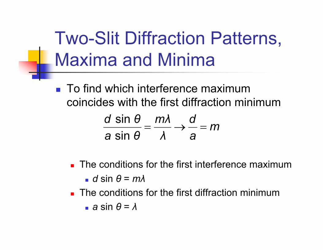
Two-Slit Diffraction Patterns, Maxima and Minima
To find which interference maximum coincides with the first diffraction minimum
The conditions for the first interference maximumd sin θ = mλ
The conditions for the first diffraction minimuma sin θ = λ
sin sin
d θ mλ d ma θ λ a
= → =

ResolutionThe ability of optical systems to distinguish between closely spaced objects is limited because of the wave nature of lightIf two sources are far enough apart to keep their central maxima from overlapping, their images can be distinguished
The images are said to be resolvedIf the two sources are close together, the two central maxima overlap and the images are not resolved
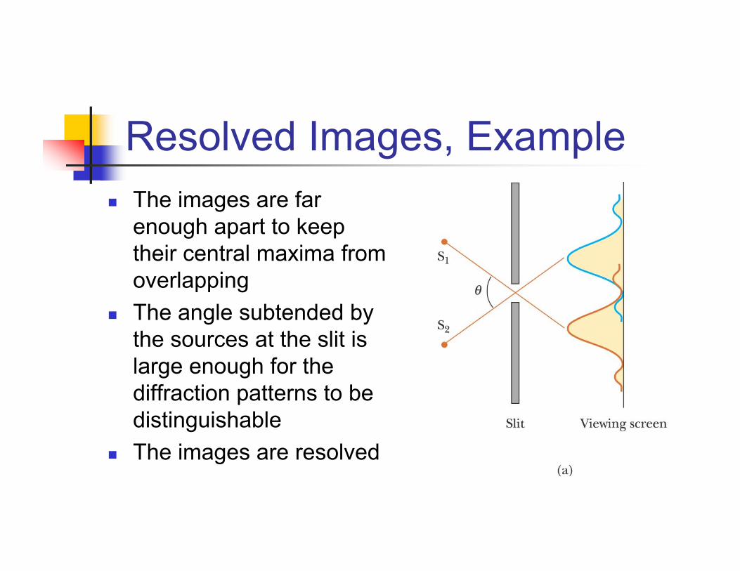
Resolved Images, ExampleThe images are far enough apart to keep their central maxima from overlappingThe angle subtended by the sources at the slit is large enough for the diffraction patterns to be distinguishableThe images are resolved

Images Not Resolved, ExampleThe sources are so close together that their central maxima do overlapThe angle subtended by the sources is so small that their diffraction patterns overlapThe images are not resolved
Resolution, Rayleigh’sCriterion
When the central maximum of one image falls on the first minimum of another image, the images are said to be just resolvedThis limiting condition of resolution is called Rayleigh’s criterion

Resolution, Rayleigh’sCriterion, Equation
The angle of separation, θmin, is the angle subtended by the sources for which the images are just resolvedSince λ << a in most situations, sin θ is very small and sin θ ≈ θTherefore, the limiting angle (in rad) of resolution for a slit of width a is
To be resolved, the angle subtended by the two sources must be greater than θmin
minλθ a=

Circular AperturesThe diffraction pattern of a circular aperture consists of a central bright disk surrounded by progressively fainter bright and dark ringsThe limiting angle of resolution of the circular aperture is
D is the diameter of the aperture
min 122. λθD
=

Circular Apertures, Well Resolved
The sources are far apartThe images are well resolvedThe solid curves are the individual diffraction patternsThe dashed lines are the resultant pattern
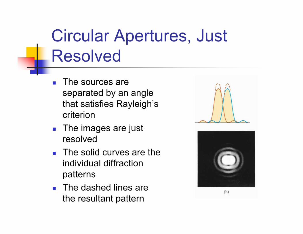
Circular Apertures, Just Resolved
The sources are separated by an angle that satisfies Rayleigh’scriterionThe images are just resolvedThe solid curves are the individual diffraction patternsThe dashed lines are the resultant pattern

Circular Apertures, Not Resolved
The sources are close togetherThe images are unresolvedThe solid curves are the individual diffraction patternsThe dashed lines are the resultant pattern

Resolution, Example
Pluto and its moon, CharonLeft: Earth-based telescope is blurredRight: Hubble Space Telescope clearly resolves the two objects
Diffraction GratingThe diffracting grating consists of a large number of equally spaced parallel slits
A typical grating contains several thousand lines per centimeter
The intensity of the pattern on the screen is the result of the combined effects of interference and diffraction
Each slit produces diffraction, and the diffracted beams interfere with one another to form the final pattern
Diffraction Grating, TypesA transmission grating can be made by cutting parallel grooves on a glass plate
The spaces between the grooves are transparent to the light and so act as separate slits
A reflection grating can be made by cutting parallel grooves on the surface of a reflective material
The reflection from the spaces between the grooves is specularThe reflection from the grooves is diffuseThe spaces between the grooves act as parallel sources of reflected light, like the slits in a transmission grating
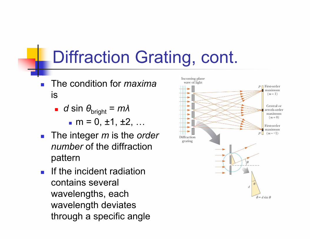
Diffraction Grating, cont.The condition for maximais
d sin θbright = mλm = 0, ±1, ±2, …
The integer m is the order number of the diffraction patternIf the incident radiation contains several wavelengths, each wavelength deviates through a specific angle
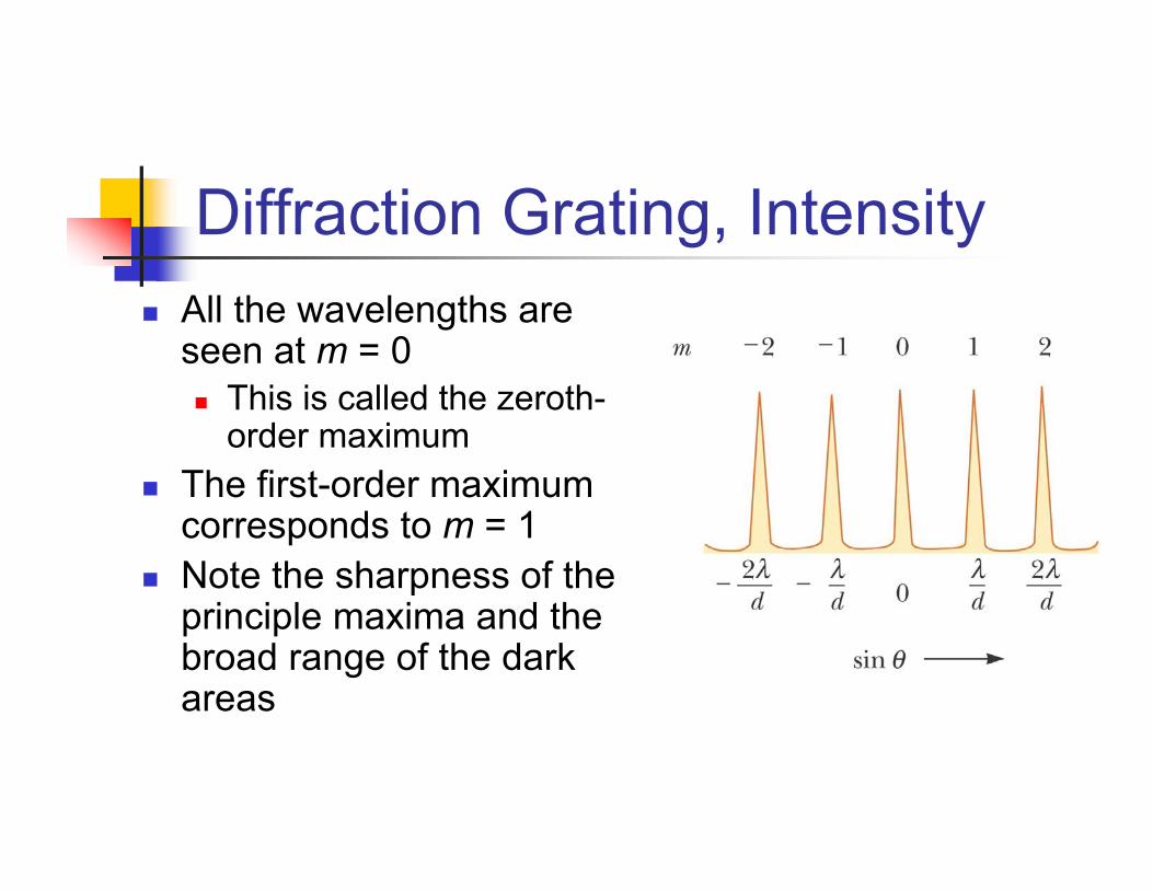
Diffraction Grating, IntensityAll the wavelengths are seen at m = 0
This is called the zeroth-order maximum
The first-order maximum corresponds to m = 1Note the sharpness of the principle maxima and the broad range of the dark areas

Diffraction Grating, Intensity, cont.
Characteristics of the intensity patternThe sharp peaks are in contrast to the broad, bright fringes characteristic of the two-slit interference patternBecause the principle maxima are so sharp, they are much brighter than two-slit interference patterns

Diffraction Grating SpectrometerThe collimated beam is incident on the gratingThe diffracted light leaves the gratings and the telescope is used to view the imageThe wavelength can be determined by measuring the precise angles at which the images of the slit appear for the various orders
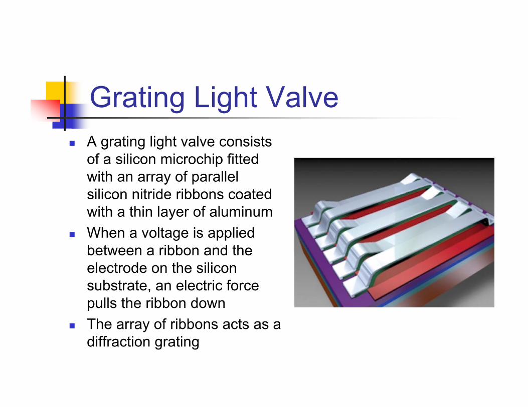
Grating Light ValveA grating light valve consists of a silicon microchip fitted with an array of parallel silicon nitride ribbons coated with a thin layer of aluminumWhen a voltage is applied between a ribbon and the electrode on the silicon substrate, an electric force pulls the ribbon downThe array of ribbons acts as a diffraction grating

Resolving Power of a Diffraction Grating
For two nearly equal wavelengths, λ1 and λ2, between which a diffraction grating can just barely distinguish, the resolving power, R, of the grating is defined as
Therefore, a grating with a high resolution can distinguish between small differences in wavelength
2 1
λ λRλ λ λ
≡ =− Δ
Resolving Power of a Diffraction Grating, cont
The resolving power in the mth-order diffraction is R = Nm
N is the number of slitsm is the order number
Resolving power increases with increasing order number and with increasing number of illuminated slits

Diffraction of X-Rays by Crystals
X-rays are electromagnetic waves of very short wavelengthMax von Laue suggested that the regular array of atoms in a crystal could act as a three-dimensional diffraction grating for x-rays

Diffraction of X-Rays by Crystals, Set-UpA collimated beam of monochromatic x-rays is incident on a crystalThe diffracted beams are very intense in certain directions
This corresponds to constructive interference from waves reflected from layers of atoms in the crystal
The diffracted beams form an array of spots known as a Laue pattern
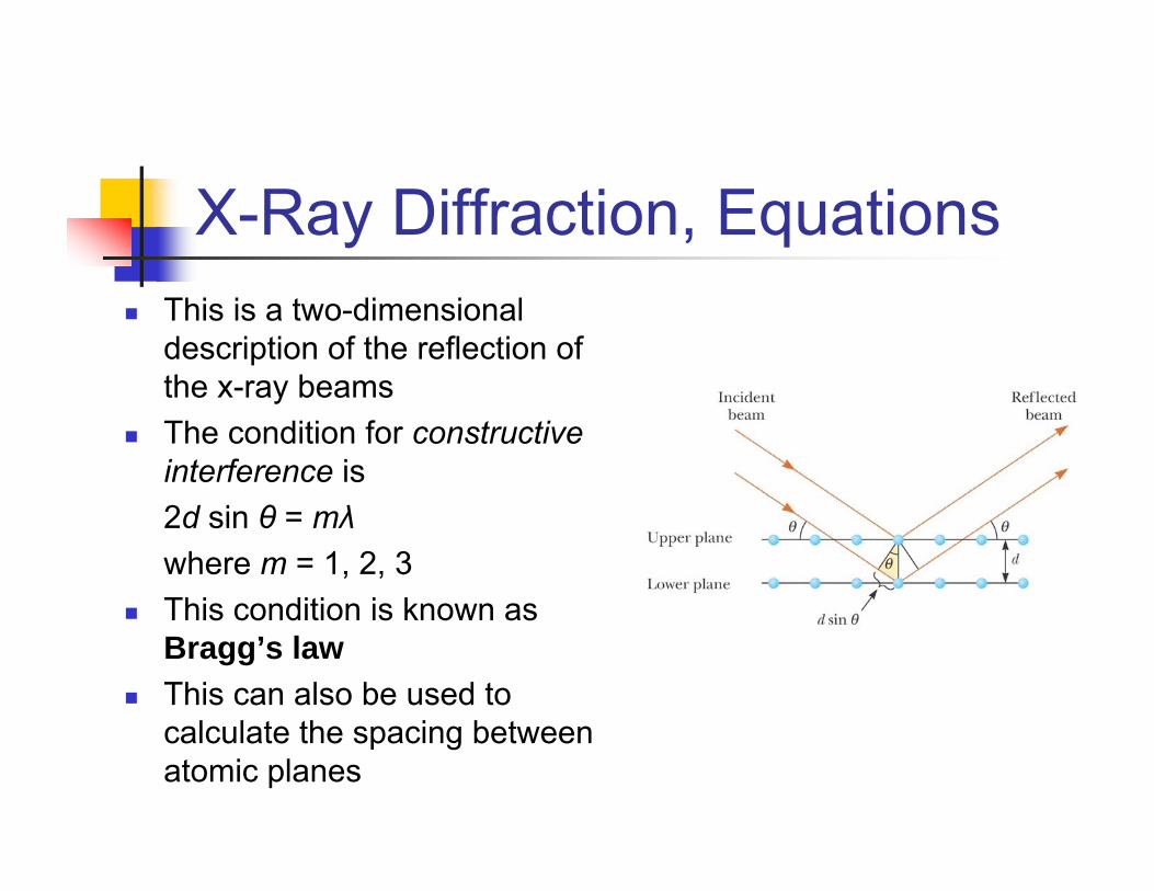
X-Ray Diffraction, EquationsThis is a two-dimensional description of the reflection of the x-ray beamsThe condition for constructive interference is2d sin θ = mλwhere m = 1, 2, 3This condition is known as Bragg’s lawThis can also be used to calculate the spacing between atomic planes

Scattering, cont.Short wavelengths (blue) are scattered more efficiently than long wavelengths (red)When sunlight is scattered by gas molecules in the air, the blue is scattered more intensely than the redWhen you look up, you see blueAt sunrise or sunset, much of the blue is scattered away, leaving the light at the red end of the spectrum