PC Assembly Guide to Building a PC How to install a Motherboard How to install a Processor – CPU...
66
PC Assembly Guide to Building a PC How to install a Motherboard How to install a Processor – CPU How to install a Memory – SDRAM How to install a Hard Disk Drive How to install a Floppy Disk Drive Referenc es How to install a Graphics Ca rd How to install a Sound Card How to install a Modem How to install CD / DVD ROM How to install Optional Unit s
-
Upload
mitchell-golden -
Category
Documents
-
view
241 -
download
2
Transcript of PC Assembly Guide to Building a PC How to install a Motherboard How to install a Processor – CPU...

PC Assembly Guide to Building a PC
How to install a Motherboard
How to install a Processor – CPU
How to install a Memory – SDRAM
How to install a Hard Disk Drive
How to install a Floppy Disk Drive
References
How to install a Graphics Card
How to install a Sound Card
How to install a Modem
How to install CD / DVD ROM
How to install Optional Units

How to install a Motherboard
The first thing you should do is unpack your ATX case. Take off the cover of your case so that you can access the inside. Place the case on a desk so that you are looking down towards the open case. Your case should come with motherboard mounting screws. If your ATX back plate it not already fitted you can fit it by placing your plate near the ATX back plate cut out and pushing the plate outwards, it should clip on.

How to install a Motherboard
Now place your motherboard on top of the mounting screw holes. Make sure your ATX devices on the motherboard such as PS/2 and parallel port are facing towards ATX back plate cut out. Gently push your motherboard towards the cut out, every devices should fit easily into its corresponding cut out, as shown below.
The screw holes on your motherboard should align with the screw holes on your case. Place your screws that came with the case into the appropriate holes and gently screw it on using a screw driver.
How to install a Motherboard
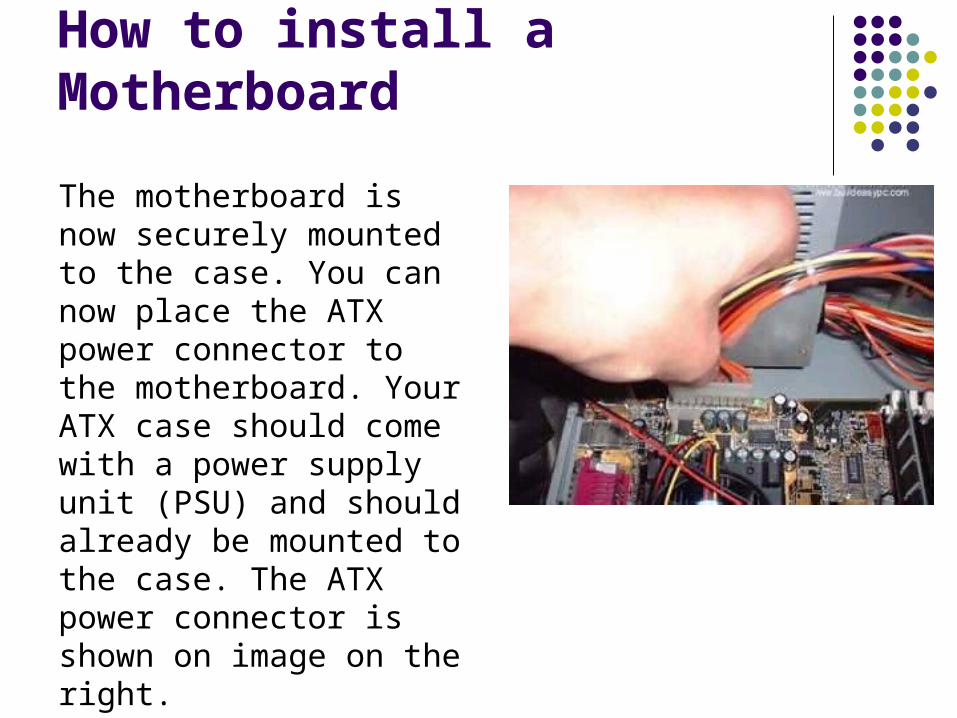
The motherboard is now securely mounted to the case. You can now place the ATX power connector to the motherboard. Your ATX case should come with a power supply unit (PSU) and should already be mounted to the case. The ATX power connector is shown on image on the right.

How to install a Motherboard
Place the ATX power connector on top of the power socket on the motherboard. Push down the power connector and it should clip onto the socket. If you try to fit the power connector the wrong way round, it won't fit, it will only fit one way. So, if the power connector does not go in, it should go in the other way round.

How to install a Processor - CPU
Locate the processor socket on your motherboard. I am installing an Intel PIII 866 processor on a socket 370 as shown on the image. The installation would be slightly different if you have a different processor i.e. Slot1 PIII CPU, P4 CPU, AMD Slot A / Socket A CPU etc.

How to install a Processor - CPU
Raise the brown lever on the socket and slowly put the processor in place. You have to make sure the pin 1 of your CPU goes into the pin 1 of your CPU socket otherwise the CPU would not get into the socket, so don't try to force it in. It will go in gently if you fit it correctly. Now close the brown lever which will securely hold the CPU in place.

How to install a Processor - CPU
If you bought a retail boxed CPU it would include a heatsink + fan. If you bought an OEM CPU make sure you got a fan that is correct for the speed of your CPU, otherwise your CPU will overheat and behave abnormally or could be damaged. Take off the plastic cover from the bottom of the CPU fan that covers the heat transfer pad. Now place the CPU fan on top the CPU and push down the metal clips on the fan so that it clips onto the CPU socket.
How to install a Processor - CPU
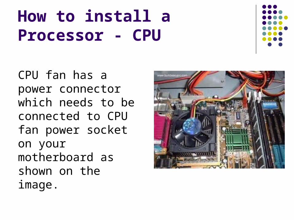
CPU fan has a power connector which needs to be connected to CPU fan power socket on your motherboard as shown on the image.

How to install a Processor - CPU
Finally, you have to specify what frequency (speed) your CPU is running at. This can be done using jumper settings, or on some modern motherboard it can be done in the BIOS, or your motherboard may have automatic detection for your CPU frequency. 6.5(multiplier) under the BIOS, which will the run the CPU at 866Mhz.

How to install a Processor - CPU
Please refer to your motherboard manual for more details. The motherboard I am using (Abit BX133) has a dip-stick jumper setting and it can be setup in the BIOS. I have left the jumper setting to default as I will use the BIOS to specify the CPU frequency. The CPU runs at the bus speed of 133Mhz therefore I will use the settings 133 *

How to install a Memory - SDRAM
Installing memory is quite simple. Find the SDRAM banks on your motherboard, they should look similar to the banks below. Notice the memory banks has a white clip on each side. Make sure you release the clips so it bends to each side.

How to install a Memory - SDRAM
Hold each corner of the SDRAM placing it on top of the bank 1. You will notice that the SDRAM has a cut at the bottom side, it is there to prevent the memory going in the wrong way round. If you are holding the SDRAM the incorrect way you will not be able insert it.
Gently push down the SDRAM and it should clip on to the memory bank. The two white clips will now become straight holding each corner of the memory.

How to install a Memory - SDRAM
If you have more that one SDRAM perform same steps as above but placing the SDRAM in memory bank 2 and so on.

How to install a Hard Disk Drive
If you look at the rear side of an IDE hard drive it should look similar to the image below.

How to install a Hard Disk Drive
The IDE/ATA connector is on the left hand side which consists of many pins. Next to the IDE connector is the jumper setting for the drive. The jumper should be set to Master, which is the default setting for a new HDD. Any other device sharing the same IDE cable should be set to Slave.
Different HDD has different jumper settings, please refer to your HDD manual for more information.

How to install a Hard Disk Drive
On the right hand side, next to the jumpers is the power connector. Every device except FDD uses this type of power connector. Figure 1 and 2 on the right shows what an ATA 66 and a power cable looks like. The ATA 66 cable which is also known as UDMA 66 cable is an advance IDE cable, which offers higher performance and data integrity than the standard IDE cable.
Figure 1

How to install a Hard Disk Drive
ATA 66 cable consists of 80 conductor cable where as the standard IDE cable consists of 40 conductor cable. I am using an ATA 66 cable because the above HDD is an ATA 100 drive which requires an ATA 66 cable.
Figure 2

How to install a Hard Disk Drive
Place your hard drive into the HDD mounting slot of your case, make sure the IDE/ATA connector is facing outwards. Screw the HDD to the case using screws provided with the HDD or the ATX case.

How to install a Hard Disk Drive
Insert the ATA 66 cable into the ATA connector of the HDD. Make sure the pin 1 on the cable is connected to pin 1 on the HDD connector. Pin 1 is the red or pink strip on the edge of an ATA cable. Most new IDE/ATA cables are designed so that it will only go in one way which will correspond to pin 1.

How to install a Hard Disk Drive
Push the power cable into the power connector as shown. The power cable is designed to go in one way, so you shouldn't have any problems.

How to install a Hard Disk Drive
Connect the other end of the ATA 66 cable to the primary ATA socket of your motherboard as shown. Make sure the pin 1 on the cable connects to the pin 1 on the ATA socket.
That's it you have successfully installed a HDD.

How to install a Floppy Disk Drive
The rear side of a floppy drive looks similar to the following image.
The black connector on the left hand side is the floppy disk connector. Figure 1 and 2 below shows what a floppy drive cable and
floppy drive power connector looks like.

How to install a Floppy Disk Drive
Figure 1 Figure 2

How to install a Floppy Disk Drive
Place the floppy drive into the FDD mounting slot as shown. Screw the drive securely into place.
Insert the floppy drive cable into the floppy
drive connector. Make sure the pin 1 on the cable connects to the pin 1 on the floppy drive connector.

How to install a Floppy Disk Drive
As you already know by now that pin 1 is the red or pink strip on the edge of the floppy drive cable. Most floppy drive cables are designed so that it will only go in on way, so you can not connect it incorrectly.

How to install a Floppy Disk Drive
Push the floppy drive power cable to the power connector. This will only go in on way.

How to install a Floppy Disk Drive
Finally connect the other end of the floppy drive cable to floppy drive connector on your motherboard. Make sure pin 1 on the cable connects to pin 1 on the connector.

How to install CD / DVD ROM
If you look at the rear side of your CD / DVD-ROM it should look similar to image shown on figure 1.
Figure 1
On the right hand side you have the power connector. Next to power connector you have the IDE connector.

How to install CD / DVD ROM
On the left hand side near the IDE connector you have the jumper settings for the DVD-ROM. The jumper is set to Master by default. I am connecting the DVD-ROM on a separate IDE cable therefore I will leave the jumper setting to Master. However if you are sharing an IDE cable with another device like HDD, then you would have to set jumper to Slave, as your HDD would be set to Master.

How to install CD / DVD ROM
Next to the jumpers you have the CD Audio-Out socket. One side of your audio cable connects to this socket and other side connects to the sound card cd-in socket. This would allow you to listen to Audio CD's on your computer.
Figure 2

How to install CD / DVD ROM
Mount your CD/DVD-ROM drive into its mounting slot. Use the supplied screws to screw the drive into position.
Figure 3

How to install CD / DVD ROM
Connect the IDE cable to the drives IDE connector. Make sure the pin 1 on the cable is connected to pin 1 on the drives IDE connector. Pin 1 is the red or pink strip on the edge of an IDE cable. Connect the other end of the IDE cable to the IDE socket on your motherboard as shown in figure 4. Again, make sure you conncet the cable to pin 1. The IDE socket could be your primary or secondary socket depending which socket you choose.

How to install CD / DVD ROM
If your HDD is on the primary IDE socket and your secondary IDE socket is free, then it is better to use your secondary IDE socket for the CD/DVD-ROM.
Finally connect the power cable to power connector and connect the audio cable to the CD Audio-Out socket as shown on figure 3.
Figure 4

How to install a Graphics Card
Most modern graphics cards are AGP based and connects to the AGP bus of the motherboard. An AGP bus (slot) looks like the following image. The brown slot is where you connect your AGP graphics card.

How to install a Graphics Card
Place your AGP card on top of the slot and gently push it down. The card should firmly sit into position.
How to install a Graphics Card
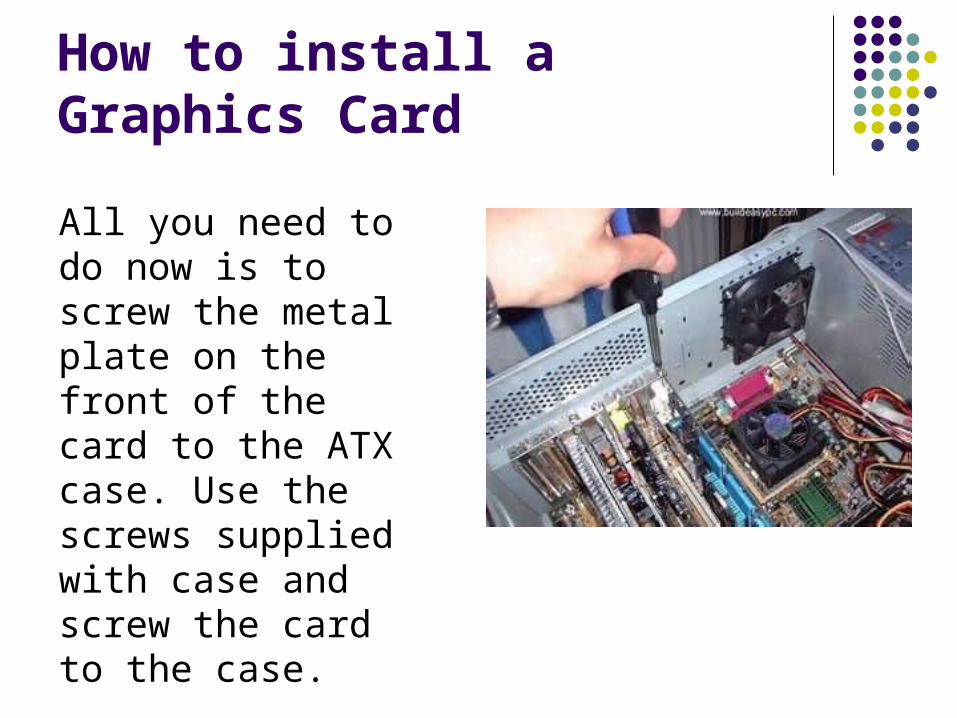
All you need to do now is to screw the metal plate on the front of the card to the ATX case. Use the screws supplied with case and screw the card to the case.

How to install a Sound Card
Most modern sound cards are designed with the PCI interface and connects to the PCI slot of your motherboard. A PCI slot looks like the slots on the following image.

How to install a Sound Card
Place your sound card on top of a chosen slot. Gently push down the card so it sits into position. Once the card is seated correctly into position, screw the card on to the case.

How to install a Sound Card
Finally insert the audio cable into the CD-IN socket. The other end of the cable should be connected to Audio-out socket on your CD/DVD-ROM drive.

How to install a Modem
Find a free PCI slot on your motherboard (assuming your modem is a PCI modem). Place your modem card on top of the slot and gently push it down into position.

How to install a Modem
Once the card has seated correctly into position, screw the card to the case using the screws supplied with the case.
Now you have installed all the prerequisite hardware devices. You can either proceed to the finalising stage, or you may want to install optional devices like a ZIP drive, CD-RW drive or a TV-Card. If you do not want to install these devices you can now proceed to the finalising stage.

Finalizing stage
Now that you have installed all the necessary hardware there are still few more things you need to do before switching on your PC for the first time.
Figure 1 - Power and Reset switch

Finalizing stage
Your ATX case has a power switch which turns the PC on, a reset switch for resetting the system, a power LED which comes on when the PC is switched on and a hard drive LED which flashes when data is being written or read from your hard drive.
You also have an internal speaker.
Figure 2 - Switch and LED connectors

Finalizing stage
The switches and LED's need to be connected to its corresponding connectors on the motherboard. Please refer to your motherboard manual to locate where the connectors are. Different motherboards place the connectors in different locations. The connectors for the switches and LED's are normally grouped together. They should look similar to the image on the previous page.

Finalizing stage
Every cable is normally labeled, they are normally named as follows, but could be slightly different on your system.
Power switch Power / PWR-SW
Reset switch Reset
Power LED Power LED / PWR-LED
Hard drive LED HDD-LED / IDE LED
Speaker SPK / Speaker

Finalizing stage
The connectors on the motherboard are also labeled but may be too small to see. Instead refer to your motherboard manual which would provide details on which pins you should connect the cables to.
The image above shows how the pins may be organised on your motherboard.

Finalizing stage
Once you have connected all the cables to the correct pins on the motherboard, you are ready to switch the PC on. At this point you can close the cover of your ATX case but don't screw it on just yet as you might have possible problems that needs rectifying.
Connect all the cables to back of ATX case. These includes the main power cable that connects to the power supply.

Finalizing stage
PS/2 mouse and keyboard that connects to the PS/2 ports. Monitor cable that connects to the graphics card port, etc.
Finally the moment has arrived. Switch on your monitor first. Your ATX power supply might have a main power switch at the back so make sure that is switched on. Now switch the PC on by pressing the power switch on the front of the ATX case.

Finalizing stage
If you have performed all the tasks without any mistakes and providing that none of the main components are faulty, the PC should boot. When the PC boots you should see the name of the BIOS manufacturer, such as AWARD BIOS displayed on your monitor. Your CPU type, speed and the amount of memory should be displayed as shown on image below.

Finalizing stage

Finalizing stage
If your motherboard has a plug and play BIOS and is set to automatic device detection by default, then you would see your IDE devices being detected followed by a prompt complaining about missing operating system. If your motherboard does not detect the hardware, then you need to proceed to the BIOS setup screen by pressing DEL or F1 or F2 depending on your motherboard.
Congratulations you have completed building your own PC.

How to install a ZIP Drive
Just like any other IDE device, a zip drive connects to an IDE cable and a power cable. The rear side of the ZIP drive looks similar to the image below.

How to install a ZIP Drive
On the left hand side you have the IDE connector. On the right hand side you have the power connector. In the middle you have the jumpers. You have to specify if the ZIP drive is being connected as a Master or a Slave device using
the appropriate jumper setting.

How to install a ZIP Drive
Place the ZIP drive into a mounting slot and screw it securely into position.

How to install a ZIP Drive
Connect the power cable and the IDE cable to the corresponding connectors. Connect the other end of the IDE cable to the IDE socket on the motherboard. Make sure the pin 1 on the cable connects to pin 1 on the motherboard IDE socket and on the ZIP drive socket.

How to install a CD Writer
The rear end of your CD-RW drive should look similar to the image on the right.
It contains all the usual connectors such an IDE connector, a power connector, audio connector, and a place to set the jumpers. Set the jumpers so the drive is configured to run as a Master device. It is best to connect your CD-RW on separate IDE cable.
How to install a CD Writer
This would avoid problems while you copy CD's on-the-fly. This means copying a source CD from a CD/DVD-ROM drive to a blank destination CD in your CD-RW drive without the source CD being copied to the hard disk first. Copying on-the-fly is less time consuming than copying the source CD to the hard disk first.

How to install a CD Writer
However if you decide to connect your CD-RW drive and another device like a DVD-ROM on the same IDE cable, it would be fine providing you make an image of your source CD on a HDD first before copying to your blank CD. You may have problems such as "buffer under run" errors if you try to copy on-the-fly.

How to install a CD Writer
Place your CD-RW drive into a mounting slot as shown. Position the drive correctly and screw it onto the case.

How to install a CD Writer
Connect the IDE and the power cable to the drive. If you want to use the CD-RW drive for playing Audio CD's then you also need to connect an audio cable to the Audio-out socket of the drive.

How to install a CD Writer
If you have a CD/DVD-ROM then the audio cable is usually connected that drive instead of the CD-RW, but there is no reason why you can't have both.
Finally the other end of the IDE cable should be connected to an IDE socket of the motherboard.

How to install a TV Card
Installing a TV card is no more difficult than installing any other PCI cards. Locate an unused PCI slot and place the card on top. Gently push card down into the slot.

How to install a TV Card
When the card is correctly in position, screw the card securely on to the case.

How to install a TV Card
Note that a TV card uses two IRQ (Interrupt Request) one for video and one for audio. It is best to place your TV card into a slot which does not conflict with an IRQ of another device. Although IRQ sharing is possible, some TV cards may behave abnormally if you are sharing IRQ's.
Finalising the stage

References
Originally Created by
Presentation by