PBS 3000QS Ver 1-2 - Used Binding Machines and Bindery … · 2015-01-29 · Table of Contents PBS...
61
PBS 3000QS AUTOMATIC INSERTER/ FINISHING SYSTEM Operation Manual Manufactured By: Gateway Bookbinding Systems Ltd 385 DeBaets Street Winnipeg, Mb, Canada R2J 4J8 Ph. (204)663-9214 Fax (204) 663-7905 Toll Free Ph. 1-800-665-7884 E-mail: [email protected] Version: PBS3000QS Version 1-2 March 2010
Transcript of PBS 3000QS Ver 1-2 - Used Binding Machines and Bindery … · 2015-01-29 · Table of Contents PBS...

PBS 3000QS AUTOMATIC INSERTER/
FINISHING SYSTEM
Operation Manual
Manufactured By: Gateway Bookbinding Systems Ltd 385 DeBaets Street
Winnipeg, Mb, Canada R2J 4J8 Ph. (204)663-9214 Fax (204) 663-7905
Toll Free Ph. 1-800-665-7884 E-mail: [email protected]
Version: PBS3000QS Version 1-2 March 2010
Table of Contents PBS 3000QS
2
Declaration of Conformity 3 General Description 4 Operator Safety 5 PBS3000QS Installation 9 PBS3000QS Tooling 10 The Machine and Its Parts 11 Getting Ready to Run Design Capabilities 17 Job Preparation 18 Punch Pitch Patterns 20 Operating Concept 21 Set-up: Step by Step Determining Coil Length 23 Determining Coil Diameter 24 Selecting and Installing Spine Formers 25 Adjusting the Carriage 27 Sidelay Angle 28 Sidelay Position 29 Book Clamp Adjustment 30 Book Clamp Comb Adjustment 31 Inserting the Coil 32 Cut and Bend Head Positioning 32 Cut and Bend Head Tilt 33 Flap Feeder 34 Coil Stop 34 Manual Test 35 Operating Tips 37 Special Adjustments
6+7mm Option Kit 41 Large Diameter Kits 42
Special Adjustments (Non-Routine)
Cut and Bend Vertical Height Adjustment 45 Coil Hold Down Proximity Switch 47 Spine Former Profile and Platen Height 48
General Maintenance 51 Troubleshooting 52 Wiring Schematics 54 Pneumatic Drawings 60
3
Declaration of Conformity According to the EC guidelines for Machines 98/37/EC and EMC Directive 89/336/EEC; The construction of the machine: Model: PBS 3000QS Type: Automated Roller Inserter & Finishing Was developed, constructed, and produced in accordance with EC guidelines 98/37/EC and Directive 89/336/EEC and with the sole responsibility of: Company: Gateway Bookbinding Systems Ltd. 11 Durand Rd. Winnipeg, MB R2J 3T1 Canada The following harmonized specifications were applied: EN 1050 EN 292 Part 2: 1991 EN 292 Part 1: 1991 EN 418 EN 954-1 EN 60204-1: 1997 EN 60529 EN 50082-1: 1997 EN 61000-3-2 & EN 61000-3-3: 1995 EN 50081-2: 1993 EN 55011: 1991 (Group 1) Class A Limit The following national norms, guidelines, and specifications were applied: - Complete technical documentation as well as the relevant manual is available.
• In the original version • In the following European Languages: English
Winnipeg, MB April 25, 2003 Chief Engineer
Place & Date Signature Title
General Description
4
General Description The PBS 3000QS is an Automated Roller Inserter, which inserts pre-cut plastic coil into a pre-punched book, and finishes the ends in a single operation. The rollers are driven by a DC motor, operating on 115 VAC supply (230 VAC optional). The cutting and crimping is performed using compressed air. Technical Specifications Machine Size: 38” wide x 23” Deep x 41” High (97 cm x 51 cm x 112 cm) Machine weight (Uncrated): 225 lbs. (102 kgs.) Maximum Safe Binding Output: 750 books / hour **Note: This value represents a safety rating and is not a performance guide or target Operating Voltages: 115 V � 10% - Single phase 50/60 Hz
230 V � 10% - Single Phase 50/60 Hz (optional) Electrical current requirements: 115 V – 2 amps 230 V – 1.4 amps Fuse ratings: 115 V 230 V Main Supply (F1) 3A Time Delay 3A Time Delay (F1-1, F1-2) Motor Drive (F2) 3A Time Delay 3A Time Delay Power Supply (F3) 1A Time Delay .5A 24V DC Outlets (F4) .75A .75A 24V DC PLC Supply (F5) .5A .5A Air Supply & Consumption: 60 psi @ 2 scfm Note: Although an internal regulator is supplied with the machine, do not exceed 100psi supply air to the machine or internal damage or injury may result.
Operator Safety
5
Important Safety Information Sound Levels
1. The equivalent continuous A-weighted sound pressure level measured at the workstation (i.e. based on operator’s position) is 76.9 dB(A).
2. The peak C-weighted instantaneous sound pressure value measured at the workstation is 97.4 dB(C) which is less than 130 dB(C).
3. The equivalent continuous A-weighted sound pressure level measured at the workstation did not exceed 85dB(A).
Explanation of Hazards & Safety Symbols
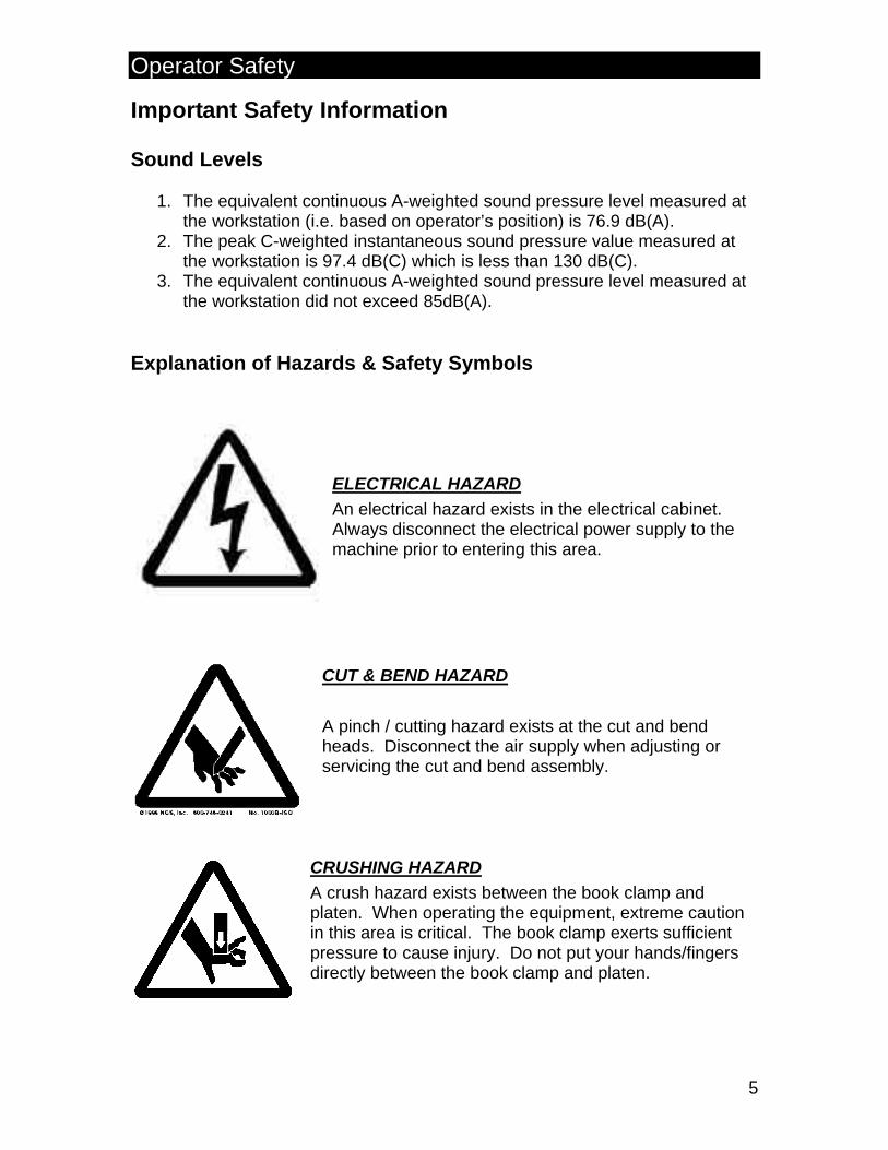
ELECTRICAL HAZARD An electrical hazard exists in the electrical cabinet. Always disconnect the electrical power supply to the machine prior to entering this area.
CUT & BEND HAZARD A pinch / cutting hazard exists at the cut and bend heads. Disconnect the air supply when adjusting or servicing the cut and bend assembly.
CRUSHING HAZARD A crush hazard exists between the book clamp and platen. When operating the equipment, extreme caution in this area is critical. The book clamp exerts sufficient pressure to cause injury. Do not put your hands/fingers directly between the book clamp and platen.

Operator Safety
6
ROLLER HAZARD A rotating part/pinch hazard exists between the rubber drive roller, the steel roller, and the platen. When operating the equipment. Do not put your fingers close to the rollers. Note: Keep hair, clothing, jewelry, or any other item that may be caught by the rollers away from them.
The PBS 3000QS is designed to insert and finish plastic spiral binding. Under no circumstances should the unit be used with any other materials or for any other purpose. Use of other binding products (i.e. steel wire) could cause personal injury and damage to the equipment. Important Safety Notes - Always disconnect the electrical supply to the machine before performing any
service work in the machine, especially when working within the electrical enclosure. All electrical repairs should only be performed by a qualified technician.
- Disconnect the electrical supply when the machine is not in use for extended
periods of time. - Disconnect the air supply when performing any service work on the machine. - Disconnect the air supply when the machine is not in use. - Do not put your hands behind the front safety cover when the machine is in
operation. The book clamp could close on your hands, causing a serious injury.
- Do not attempt to clear a piece of coil from the machine while it is running.
The rubber roller has enough rotating force to pull a hand into the platen teeth, potentially causing injury.
- Do not loosen the cut and bend heads while air pressure is still applied to the
machine. The cut and bend heads are always under pressure, and may move suddenly if loosened, potentially pinching a finger.
- Do not place hands near the flap feeder shaft while it is rotating. The flap
feeder block is rotating at high speed, and could cause injury.

Operator Safety
7
- Use caution when working near the on the platen and comb. There are sharp edges that can cause cuts.
- Always grasp the top of the book clamp when lifting or lowering the platen.
The platen may swing down suddenly if dropped, and could injure fingers caught under it.
- Do not operate the machine without safety and/or machine covers in
place. There are many pinch points and rotating parts that could cause serious injuries.
If in doubt about any area of the machine, please do not hesitate to contact your supplier or call the manufacturer direct at 1-800-665-7884. Operator Obligations: • It is imperative that all operators be familiar with the basic safety information
in order to be able to ensure safe and trouble-free operation of this machine. • All persons operating this machine must carefully study this instruction
manual, paying particular attention to the section "Important Safety Information”.
• The operator/staff is under obligation to allow only those persons to work at the machine who are familiar with safety and the prevention of accidents and who have been trained to operate this machine, having read and fully understood the section on safety information and warnings, confirming that comprehension with their signature.
• The PBS 3000QS has been built according to the latest state of the art technology and according to the standard safety regulations. Nevertheless, the operation of the machine may cause danger to the operator. The machine must only be operated for its intended purpose and in a safe operating condition. Any fault that might disturb the safety of the machine must be eliminated before operating the machine.
• The machine should be plugged into a properly connected grounded safety outlet only.
Operator Safety
8
Claims The intended purpose of the PBS 3000QS is to insert pre-cut lengths of plastic spiral into pre-punched books, cutting and bending the ends of the plastic spiral to finish it in the book. All claims will be denied if they are caused by any of the reasons listed below: • The machine is used for a purpose for which it was not intended. • Improper operation, maintenance, installation, or assembly of the machine. • Operation of the machine if the safety equipment is defective or if the safety
devices have not been installed or are not working properly. • If the instructions provided in this manual regarding installation, operation
and/or maintenance of the machine are not observed. • If the construction of the machine has been on one’s own authority. • If the machine parts subject to wear and tear are not sufficiently maintained. • If any repair work has been done improperly • In case of catastrophes, damage caused by a foreign object, or an act of God

PBS 3000QS Installation
9
PBS 3000QS Installation Use caution when handling the PBS 3000QS. Lift only the underside of the main body. A minimum of 2 persons is needed to safely lift this machine. Basic requirements
1. Compressed Air – 60psi @ 2scfm (Do not exceed 100PSI)
2. Electricity – 115VAC �10%, 50/60 Hz @ 2 amps (230 VAC �10%, 50/60 Hz Single phase @ 1.4 amps also available)
Follow these steps to install the PBS 3000QS:
1. Open the crate, using a #2 Phillips screwdriver and a pry bar. 2. Remove packaging from the machine. 3. Remove the bolts (and strapping if applicable) that secure the machine
to the shipping brackets on the pallet, using a 9/16” wrench or socket. 4. Inspect the machine for any shipping damage. 5. Lift the machine off the pallet and position it on a stable, level surface
capable of supporting its weight (210 lbs./ 95 kg). 6. Attach air and electrical power as detailed below.
To attach electrical power, first take the cord out of the toolbox. Attach the female end to the mating connector on the left side of the machine just below the main power switch (A). Attach the male end to a standard 120 volt outlet (230 V if applicable). Note: A filtered power bar is recommended, especially in areas where there is a history of power surges or spikes. To attach air, one of two things is required: 1. A fixed hose or pipe connection that will be permanently
threaded into the pneumatic supply connection. 2. A quick connect that is compatible with what is used elsewhere
in your plant. The threaded fitting in the side of the QS is ¼” NPT.
The QS is supplied with a Milton type M quick connect fitting like the one show on the right. >>>>>>
A
B

PBS 3000QS Tooling
10
PBS 3000QS Tooling/Parts Each PBS 3000QS comes with the tooling, parts, and basic hand tools required to do a basic set-up of the machine. There is a tool kit supplied with each machine that contains the following: 1. Two spare drive belts (Non-North American Machines Only) 2. One bag of assorted extra screws 3. One set of Flap Feeders 4. One 1/8” T-handle Allen key 5. 1/8”, 7/64”, 3/32” Hex Keys 6. One pair of side cutters 7. Spare fuses 8. Jogging window inserts 9. 3/8” Nut Driver (only with pitch conversion kit) Note: Check the toolkit immediately when the machine is unpacked. Notify your salesperson of any deficiencies. Tooling: The standard machine contains 15 sets of Spine Formers to insert spiral sizes 6mm-20mm. The standard cut and bend heads supplied with the machine will cut and crimp coil from 8mm up to 20mm. It should be noted that sizes 6+7 will require the 6+7 kit which contains special small diameter cut and bend heads and a flat edged book clamp insert. This option kit is available separately. For spiral sizes larger than 20mm, an oversize pitch kit is required and will allow insertion of spiral up to 30mm in diameter. The oversize kit is available in pitches 2.5:1 and 3:1.
The Machine and Its Parts
11
PBS 3000QS Parts – Front View
1 2
3
4
5
6
7
9
10
11 12
20
19
18
18
17 14 15
16
13
8
16
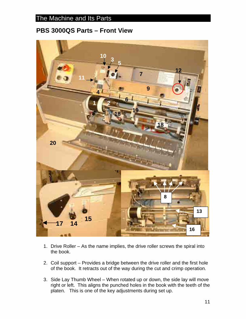
1. Drive Roller – As the name implies, the drive roller screws the spiral into
the book.
2. Coil support – Provides a bridge between the drive roller and the first hole of the book. It retracts out of the way during the cut and crimp operation.
3. Side Lay Thumb Wheel – When rotated up or down, the side lay will move
right or left. This aligns the punched holes in the book with the teeth of the platen. This is one of the key adjustments during set up.
The Machine and Its Parts
12
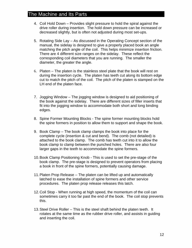
4. Coil Hold Down – Provides slight pressure to hold the spiral against the
drive roller during insertion. The hold down pressure can be increased or decreased slightly, but is often not adjusted during most set-ups.
5. Rotating Side Lay – As discussed in the Operating Concept section of the
manual, the sidelay is designed to give a properly placed book an angle matching the pitch angle of the coil. This helps minimize insertion friction. There are 4 different size ranges on the sidelay. These reflect the corresponding coil diameters that you are running. The smaller the diameter, the greater the angle.
6. Platen – The platen is the stainless steel plate that the book will rest on
during the insertion cycle. The platen has teeth cut along its bottom edge cut to match the pitch of the coil. The pitch of the platen is stamped on the LH end of the platen face.
7. Jogging Window – The jogging window is designed to aid positioning of the book against the sidelay. There are different sizes of filler inserts that fit into the jogging window to accommodate both short and long binding edges.
8. Spine Former Mounting Blocks - The spine former mounting blocks hold
the spine formers in position to allow them to support and shape the book.
9. Book Clamp – The book clamp clamps the book into place for the complete cycle (insertion & cut and bend). The comb (not detailed) is attached to the book clamp. The comb has teeth cut into it to allow the book clamp to clamp between the punched holes. There are also four larger gaps in the teeth to accommodate the spine formers.
10. Book Clamp Positioning Knob - This is used to set the pre-stage of the
book clamp. The pre-stage is designed to prevent operators from placing a book in front of the spine formers, potentially causing damage.
11. Platen Prop Release – The platen can be lifted up and automatically
latched to ease the installation of spine formers and other service procedures. The platen prop release releases this latch.
12. Coil Stop - When running at high speed, the momentum of the coil can
sometimes carry it too far past the end of the book. The coil stop prevents this.
13. Steel Drive Roller – This is the steel shaft behind the platen teeth. It
rotates at the same time as the rubber drive roller, and assists in guiding and inserting the coil.
The Machine and Its Parts
13
14. Carriage Adjustment Gauge (coil size gauge) – The carriage adjustment gauge is used to set the proper position of the carriage, or set the machine for the coil size you have chosen. The higher the adjustment gauge, the larger the coil diameter is being used.
15. Carriage Adjustment Knob – Once loosened, the carriage adjustment is
used to set the carriage adjustment gauge.
16. Cut and Bend Head Rocker Shaft – This shaft is rotated by a cylinder inside the machine to tip the cut and bend heads forward at the appropriate time in the cycle.
17. Rocker Tilt Adjuster – This adjustment knob is used to set how far the cut
and bend heads can tilt in.
18. Cut and Bend Heads – Once the coil has been inserted, the cut and bend heads do the finishing operation on the book. They cut off the excess coil at each end and crimp in the cut ends, preventing the coil from backing out of the book.
19. Flap Feeders – The flap feeders are used to aid insertion by ‘tapping’ the
coil as it inserts.
20. Coil Shelf – The coil shelf is intended to hold a box of coil. It is not intended to hold books. (Not shown on picture)
The Machine and Its Parts
14
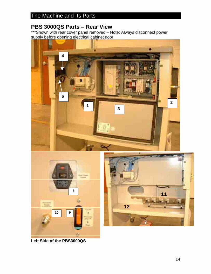
PBS 3000QS Parts – Rear View ***Shown with rear cover panel removed – Note: Always disconnect power supply before opening electrical cabinet door
12
3
6
4
5
9
8
10
Left Side of the PBS3000QS
7
11
12
The Machine and Its Parts
15
1. Coil Chute – The coil chute is intended to funnel off-cut pieces of coil into a
box or wastebasket placed beneath it. 2. Serial Number/Specification Label – (located on LH side of machine) This
label denotes the machine’s serial number, power requirements and year of manufacturing.
3. Electrical Enclosure – This houses all the electrical controls for the machine.
Only a qualified technician/electrician should open this cabinet. (Disconnect power supply before opening this cabinet)
4. Emergency Air Release/Soft Start – This valve acts primarily as an
emergency air release, exhausting all air from the machine when the emergency stop is pressed. It also acts as a ‘soft start’ by controlling the rate that air is allowed back into the machine when the emergency stop button is pulled out.
5. Valve Bank – This has the pneumatic valves that control all the pneumatic
operations of the machine. 6. Air Regulator – This regulates the air pressure to the machine. It is factory
set to 60 psi, and should be left at that pressure. 7. Foot Pedal – The foot pedal is primarily used to start the automatic cycle. It is
also used to interrupt the cycle if required, or reset the machine in manual mode.
8. Plug-in/Main Power Switch – This is where the female end of the power cord
is plugged in. It is also where the main power switch to the machine is. (Located on the left side when looking at the front of the machine)
9. Air Release Valve – This valve manually exhausts air from the machine, and
is primarily used in set-up. (Located on the left side when looking at the front of the machine)
10. Main Air Supply Connection – Serves as the main supply air connection to the
inserter. This is factory supplied with a Milton type M quick connect fitting. 11. Platten / Bookclamp Insert Holder - Provides protective storage for additional
pitch inserts for both the platen and the bookclamp. 12. Tool Shelf – Provides a location for the inserter tool box or additional
components .

The Machine and Its Parts
16
PBS 3000QS Controls With the exception of the foot pedal, all of the PBS 3000QS operator controls are on the dash panel on the front left of the machine. Below is a brief explanation of the function of each one. 1. Emergency Stop – This is intended only for use
as a true emergency stop. When it is pulled out, it lights up, indicating the machine has power. It disrupts both air and electrical power to the operator side of the machine. Note: This is only intended for emergency use, or shut-off of the machine during short periods of inactivity. For service, critical set-up operations that require removal of all power to the machine, or shut-down at the end of the shift, the main power switch and main air shut-off must be used. The E-stop does not disconnect power or air to the control cabinet of the machine.
2. Manual Step – This button is used to step the machine through its manual
program. It is only active in manual mode. The safety covers and platens must be closed to use this button.
3. Mode Switch (Auto /Manual) – This selector lets the operator choose the
desired operating mode. Manual is used when the operator is setting the machine up and wishes to step the machine through its program manually. The manual mode is explained in-depth in the basic set-up section of this manual. Auto run mode is used when the machine is operated in run-mode automatically, and is explained fully in the Running the Machine section of this manual.
4. Variable Speed – This dial controls the speed of insertion by controlling the
speed of the rubber drive roller and the steel drive roller (clockwise for faster, counter-clockwise for slower).
12
3 4

Getting Ready to Run
17
PBS 3000QS Design/Capabilities The PBS 3000QS has been designed to: a) Insert pre-cut lengths of plastic coil binding into pre-punched books, and b) Cut and bend (finish) the ends of the coil. This will happen in a single, automatic cycle. The PBS 3000QS is capable of inserting coil diameters ranging from 6mm(*) up to and including 20mm. Actual insertion capabilities are dependent on the hole size and shape. Refer to Table 1 below for the range of insertion for some of the common hole patterns. Note: This table is a guideline. It is possible to run sizes beyond the sizes detailed below for a given hole pattern. The machine would just require a more precise set-up. For sizes larger than 20mm, the oversize kit is required.
Table 1
Coil Diameter Round – 4mm round hole
Oval Hole (Double-D) – 5 x 4mm
Oversize Oval Hole (Double-D) – 6.5 x
5.5(**) 6mm (*) / / 7mm (*) / / 8mm / / 9mm / / 10mm / / 11mm / 12mm / 13mm / 14mm / 15mm / / 16mm / / 17mm / / 18mm / / 19mm / / 20mm / / 23mm / 25mm / 28mm / 30mm /
(*) – Only with optional 6&7mm cut and bend heads. (**) – Only with optional 3:1 or 2.5:1 Pitch Conversion Kit Note: Larger oval holes make for the easiest insertion of coil.

Getting Ready to Run
18
Job Preparation Consistency is the focus of proper job preparation. 1. Consistent punching. Since the book cannot be moved to help coil insertion
once it is clamped, punching consistency is one of the keys to high productivity.
2. Consistent trimming. A properly trimmed book allows for consistent book placement. If the pages and cover are trimmed differently, this will hamper insertion.
3. Consistent punch pattern. This concept is very important for this machine. The starting hole should not be further from the end of the page than the gaps between any two holes. The coil shouldn’t have to stretch into the first hole. Figures 1 illustrates this. Also if the hole pattern shifts from side to side due to unstable punching, the effective hole size will be greatly reduced.
Note: While it is slightly possible to ‘offset’ the punch pattern so the wide edge (as in Figure 1) is on the trail (right) edge of the book, this will be difficult to set up to run properly and consistently. The PBS 3000QS was designed to operate ideally when both edges of the book are trimmed to be no wider than the gap between two loops of coil, so the coil can enter and exit the book smoothly.
Figure 1 Incorrect edge margin. Coil will not insert. Book requires trimming
Getting Ready to Run
19
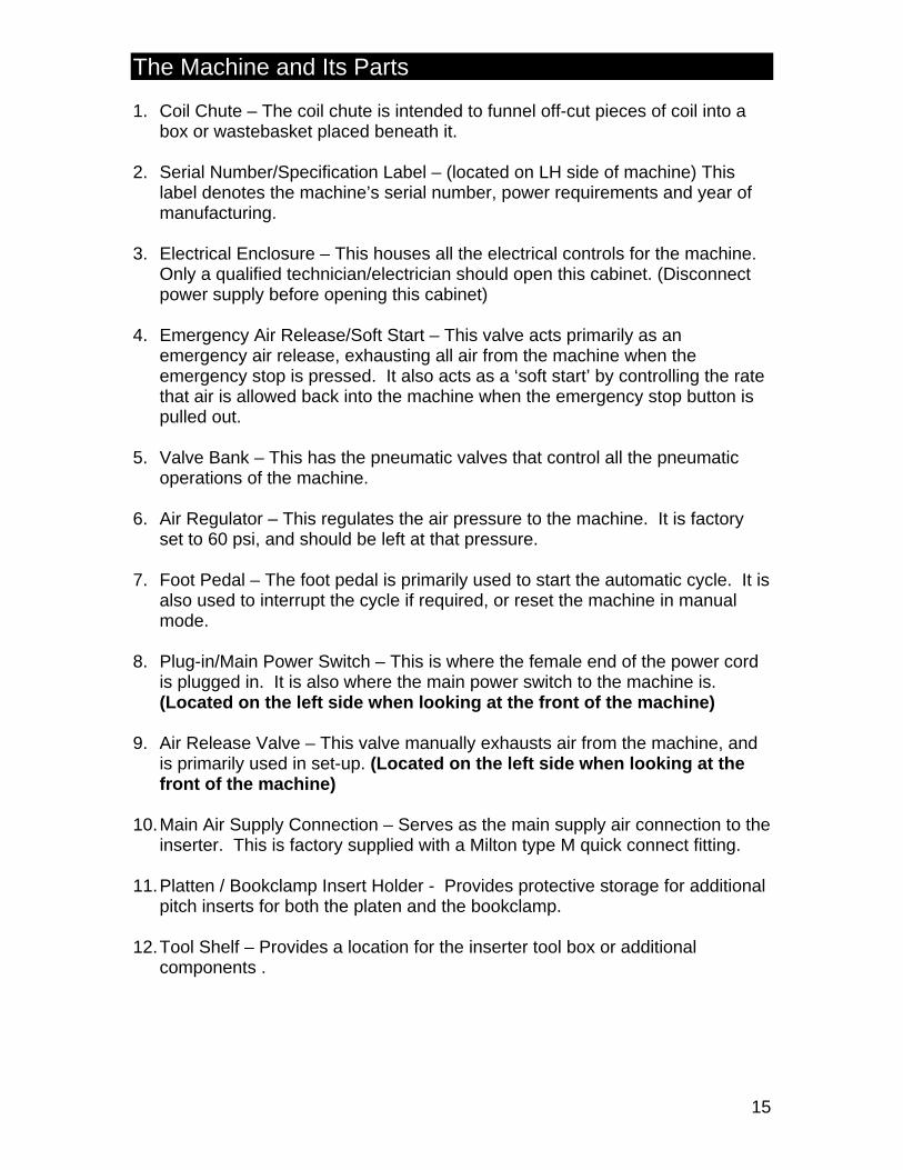
4. Consistent Punch Back Gauge. The PBS 3000QS is designed to insert
books with a specific punch back gauge. Figure 3 & 4 illustrate these requirements.
Proper preparation of the job cannot be stressed enough. Consistent punching, square trim, and consistent quality coil are all critical for consistent operation of the PBS 3000QS.
Pitch A Max. Edge Margin
6mm .078
4:1 .092
.2745 .090
Getting Ready to Run
20
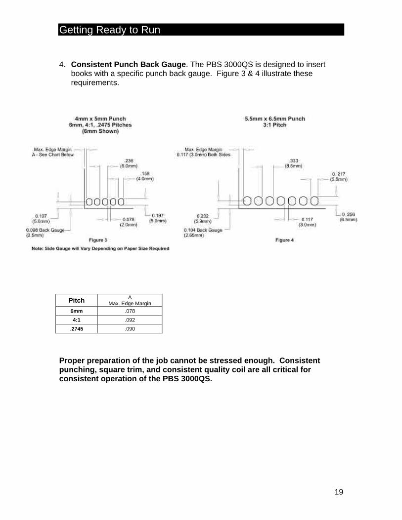
Punch Pitch Patterns The PBS 3000QS comes in several different pitch options. 1. True 4:1(four holes/inch) – This is a very common pitch, and many facilities
already have punching equipment in this pitch. For ideal operation in many sizes, however, the books need to be trimmed to achieve the ideal punch pattern needed for optimal operation with standard 8.5” and 11” edges.
2. 6mm (6mm between hole centers) – This is also a very common pitch, and generally needs less trimming on the standard paper sizes.
3. 0.2475 (0.2475” between hole centers) – This pitch was developed for customers that run 8 ½ x 11 exclusively (also A4 sizes). It fits 44 holes into an 11” edge, allowing a comfortable margin on both edges.
4. 3:1 Pitch (three holes/inch) or 2.5 : 1 (2.5 holes per inch) – Are used for larger diameter coil because the hole size can be larger than the above mentioned pitches, making for easier coil insertion. The PBS3000QS uses these pitch patterns for all coils larger than 20mm, and up to 30mm.
The PBS3000QS uses quick change pitch inserts allowing the change of one pitch to another as required from job to job. Pitch change kits are available separately and most common pitches are stocked.
In addition to the above mentioned pitch patterns, additional pitch patterns are available. Contact your representative for additional details.
Getting Ready to Run
21
PBS 3000QS Operating Concept There are two basic requirements for effective operation of the PBS 3000QS:
21. A good basic set-up. This is explained in-depth in a later section of this manual.
22. Proper placement and shaping of the book.
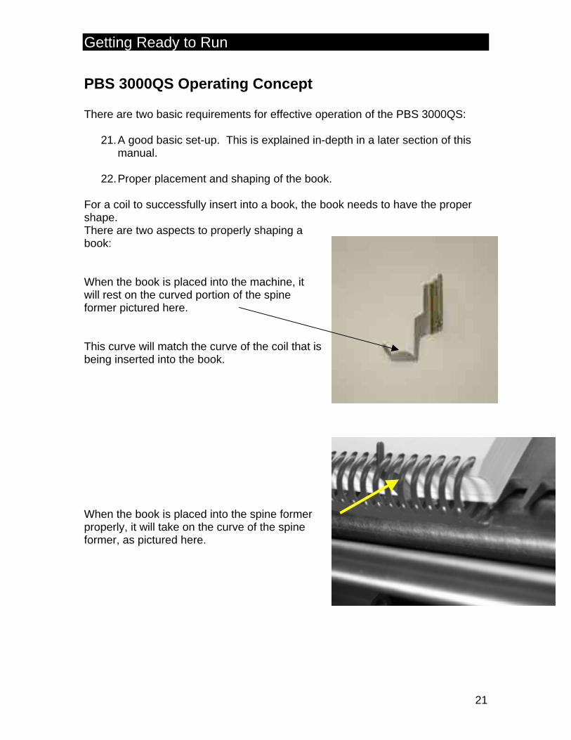
For a coil to successfully insert into a book, the book needs to have the proper shape. There are two aspects to properly shaping a book: When the book is placed into the machine, it will rest on the curved portion of the spine former pictured here. This curve will match the curve of the coil that is being inserted into the book. When the book is placed into the spine former properly, it will take on the curve of the spine former, as pictured here.
Getting Ready to Run
22
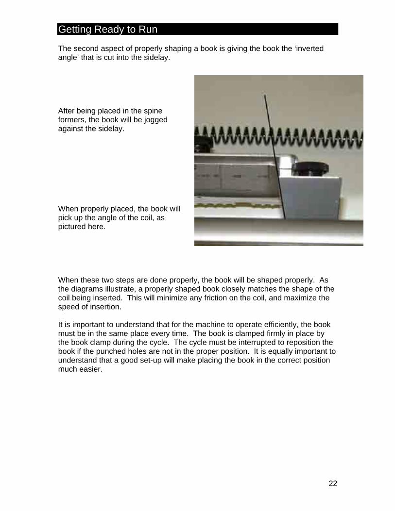
The second aspect of properly shaping a book is giving the book the ‘inverted angle’ that is cut into the sidelay. After being placed in the spine formers, the book will be jogged against the sidelay. When properly placed, the book will pick up the angle of the coil, as pictured here. When these two steps are done properly, the book will be shaped properly. As the diagrams illustrate, a properly shaped book closely matches the shape of the coil being inserted. This will minimize any friction on the coil, and maximize the speed of insertion. It is important to understand that for the machine to operate efficiently, the book must be in the same place every time. The book is clamped firmly in place by the book clamp during the cycle. The cycle must be interrupted to reposition the book if the punched holes are not in the proper position. It is equally important to understand that a good set-up will make placing the book in the correct position much easier.
Set-up: Step by Step
23
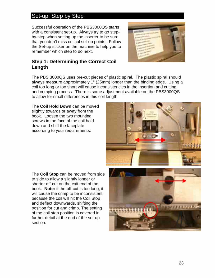
Successful operation of the PBS3000QS starts with a consistent set-up. Always try to go step-by-step when setting up the inserter to be sure that you don’t miss critical set-up points. Follow the Set-up sticker on the machine to help you to remember which step to do next. Step 1: Determining the Correct Coil Length The PBS 3000QS uses pre-cut pieces of plastic spiral. The plastic spiral should always measure approximately 1” (25mm) longer than the binding edge. Using a coil too long or too short will cause inconsistencies in the insertion and cutting and crimping process. There is some adjustment available on the PBS3000QS to allow for small differences in this coil length. The Coil Hold Down can be moved slightly towards or away from the book. Loosen the two mounting screws in the face of the coil hold down and shift the faceplate according to your requirements. The Coil Stop can be moved from side to side to allow a slightly longer or shorter off-cut on the exit end of the book. Note: if the off-cut is too long, it will cause the crimp to be inconsistent because the coil will hit the Coil Stop and deflect downwards, shifting the position for cut and crimp. The setting of the coil stop position is covered in further detail at the end of the set-up section.
Set-up: Step by Step
24
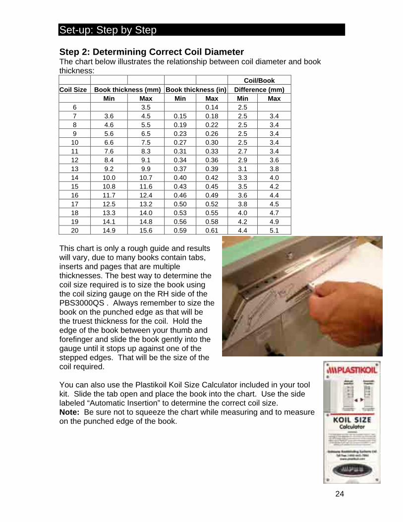
Step 2: Determining Correct Coil Diameter The chart below illustrates the relationship between coil diameter and book thickness: Coil/Book Coil Size Book thickness (mm) Book thickness (in) Difference (mm) Min Max Min Max Min Max
6 3.5 0.14 2.5 7 3.6 4.5 0.15 0.18 2.5 3.4 8 4.6 5.5 0.19 0.22 2.5 3.4 9 5.6 6.5 0.23 0.26 2.5 3.4 10 6.6 7.5 0.27 0.30 2.5 3.4 11 7.6 8.3 0.31 0.33 2.7 3.4 12 8.4 9.1 0.34 0.36 2.9 3.6 13 9.2 9.9 0.37 0.39 3.1 3.8 14 10.0 10.7 0.40 0.42 3.3 4.0 15 10.8 11.6 0.43 0.45 3.5 4.2 16 11.7 12.4 0.46 0.49 3.6 4.4 17 12.5 13.2 0.50 0.52 3.8 4.5 18 13.3 14.0 0.53 0.55 4.0 4.7 19 14.1 14.8 0.56 0.58 4.2 4.9 20 14.9 15.6 0.59 0.61 4.4 5.1
This chart is only a rough guide and results will vary, due to many books contain tabs, inserts and pages that are multiple thicknesses. The best way to determine the coil size required is to size the book using the coil sizing gauge on the RH side of the PBS3000QS . Always remember to size the book on the punched edge as that will be the truest thickness for the coil. Hold the edge of the book between your thumb and forefinger and slide the book gently into the gauge until it stops up against one of the stepped edges. That will be the size of the coil required. You can also use the Plastikoil Koil Size Calculator included in your tool kit. Slide the tab open and place the book into the chart. Use the side labeled “Automatic Insertion” to determine the correct coil size. Note: Be sure not to squeeze the chart while measuring and to measure on the punched edge of the book.

Set-up: Step by Step
25
Step 3: Selecting Spine Formers The spine formers are located behind the front safety guard. There is a pair of spine formers in each size from 6mm to 20mm (15 sets total). Use the spine former size that corresponds to the coil size indicated by the sizing gauge on the side of the machine.
Always choose the spine former size that best suits the book. If the spine former is too small it will push up the front and rear pages of the book and push those holes out of position. If the spine former is too large, the pages will splash outwards and the holes will again not be in the right position to insert the coil.
Note: Some exceptions can be made. For example, if you only have a size 10mm coil in stock, but the book measures as requiring a 9mm coil, use the 9mm spine formers, but then do the rest of the set-up based on the 10mm coil. Generally, you can go one coil size larger if required.
Set-up: Step by Step
26
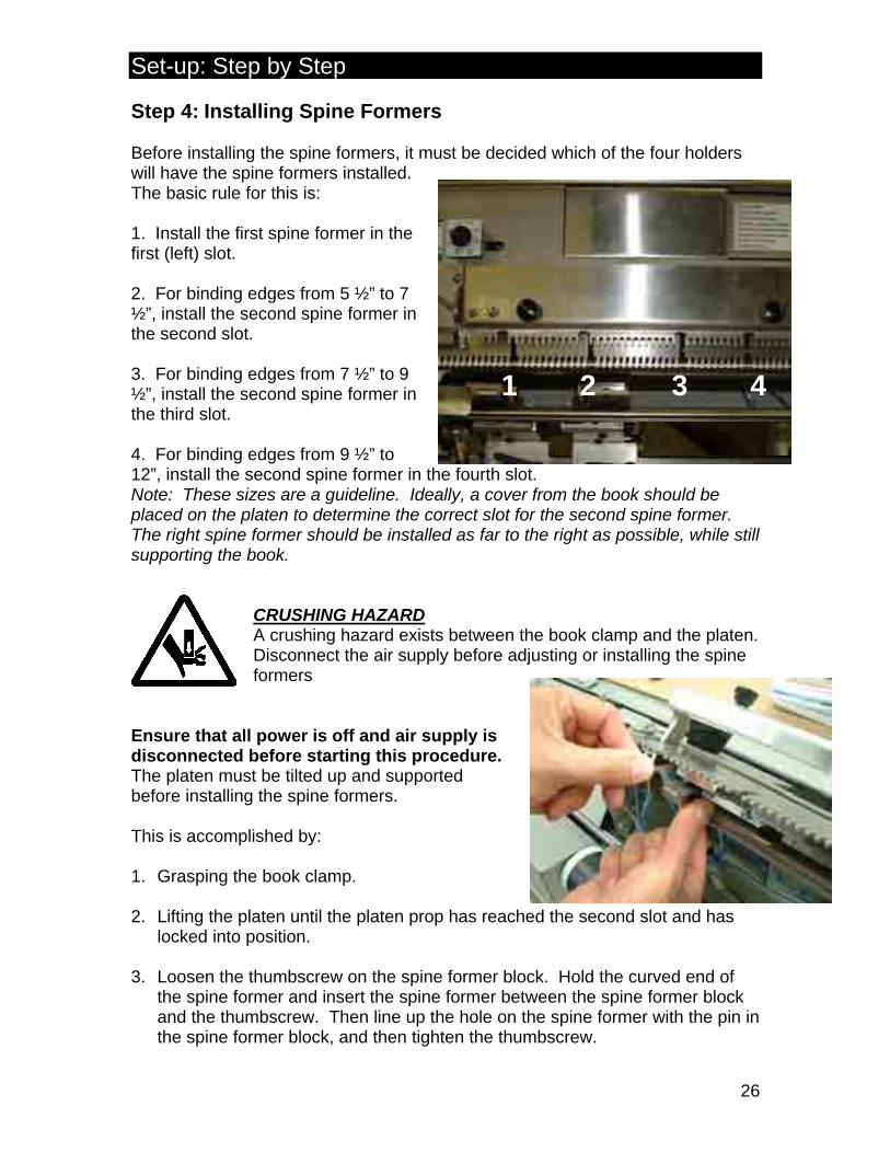
Step 4: Installing Spine Formers Before installing the spine formers, it must be decided which of the four holders will have the spine formers installed. The basic rule for this is: 1. Install the first spine former in the first (left) slot. 2. For binding edges from 5 ½” to 7 ½”, install the second spine former in the second slot. 3. For binding edges from 7 ½” to 9 ½”, install the second spine former in the third slot. 4. For binding edges from 9 ½” to 12”, install the second spine former in the fourth slot. Note: These sizes are a guideline. Ideally, a cover from the book should be placed on the platen to determine the correct slot for the second spine former. The right spine former should be installed as far to the right as possible, while still supporting the book.
CRUSHING HAZARD A crushing hazard exists between the book clamp and the platen. Disconnect the air supply before adjusting or installing the spine formers
Ensure that all power is off and air supply is disconnected before starting this procedure. The platen must be tilted up and supported before installing the spine formers. This is accomplished by: 1. Grasping the book clamp. 2. Lifting the platen until the platen prop has reached the second slot and has
locked into position. 3. Loosen the thumbscrew on the spine former block. Hold the curved end of
the spine former and insert the spine former between the spine former block and the thumbscrew. Then line up the hole on the spine former with the pin in the spine former block, and then tighten the thumbscrew.
1 2 3 4
Set-up: Step by Step
27
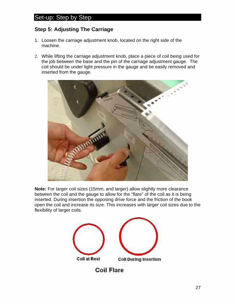
Step 5: Adjusting The Carriage 1. Loosen the carriage adjustment knob, located on the right side of the
machine. 2. While lifting the carriage adjustment knob, place a piece of coil being used for
the job between the base and the pin of the carriage adjustment gauge. The coil should be under light pressure in the gauge and be easily removed and inserted from the gauge.
Note: For larger coil sizes (15mm, and larger) allow slightly more clearance between the coil and the gauge to allow for the “flare” of the coil as it is being inserted. During insertion the opposing drive force and the friction of the book open the coil and increase its size. This increases with larger coil sizes due to the flexibility of larger coils.
Set-up: Step by Step
28
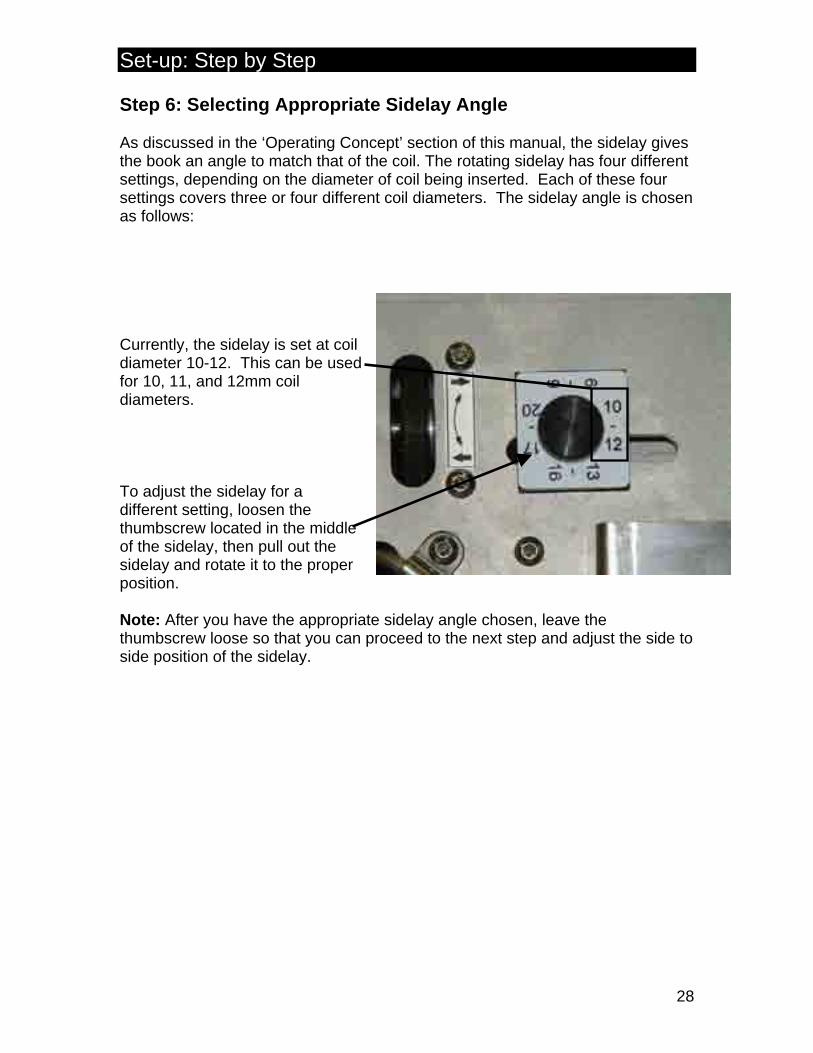
Step 6: Selecting Appropriate Sidelay Angle As discussed in the ‘Operating Concept’ section of this manual, the sidelay gives the book an angle to match that of the coil. The rotating sidelay has four different settings, depending on the diameter of coil being inserted. Each of these four settings covers three or four different coil diameters. The sidelay angle is chosen as follows: Currently, the sidelay is set at coil diameter 10-12. This can be used for 10, 11, and 12mm coil diameters. To adjust the sidelay for a different setting, loosen the thumbscrew located in the middle of the sidelay, then pull out the sidelay and rotate it to the proper position. Note: After you have the appropriate sidelay angle chosen, leave the thumbscrew loose so that you can proceed to the next step and adjust the side to side position of the sidelay.
Set-up: Step by Step
29
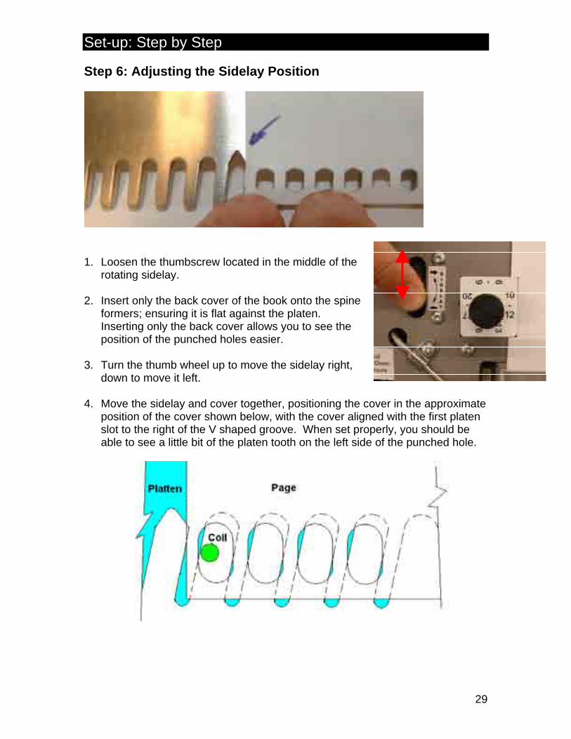
Step 6: Adjusting the Sidelay Position
1. Loosen the thumbscrew located in the middle of the
rotating sidelay. 2. Insert only the back cover of the book onto the spine
formers; ensuring it is flat against the platen. Inserting only the back cover allows you to see the position of the punched holes easier.
3. Turn the thumb wheel up to move the sidelay right,
down to move it left. 4. Move the sidelay and cover together, positioning the cover in the approximate
position of the cover shown below, with the cover aligned with the first platen slot to the right of the V shaped groove. When set properly, you should be able to see a little bit of the platen tooth on the left side of the punched hole.

Set-up: Step by Step
30
From this point, the set-up is done with the machine turned ON, the emergency stop button released (the red center lit), the air shut-off turned to the ON position and the mode selector switch turned to the Manual setting. In manual mode, the inserter steps through the insertion cycle one step
at a time for each press of the Manual Step button. In manual, the foot pedal acts as a reset and will take you back to the start position. The safety door and platen must both be in the closed position to allow the manual step button to progress through the cycle. You can open the safety door to make adjustments, but it must be
re-closed before pressing the Manual Step and progressing to the next step. Step 7: Book Clamp Adjustment The first step in adjusting the book clamp is setting the pre-stage position of the book clamp. The pre-stage is designed so the operator cannot place the book in front of the spine formers, potentially causing damage to the spine formers. It also provides a “funneling” action to guide the book onto the spine formers. 1. Close the safety cover and place a pre-punched book into the spine formers.
Press the manual step button once. 2. Turn the book clamp positioning knob
counter-clockwise to open the clamp fully. Turn the knob clockwise to close the book clamp down towards the book.
3. When correctly positioned, the book clamp
should be approximately 1/8” off the book, as pictured above. If the clamp is positioned too close, it will make it difficult to place the book into the spine formers. A good check is to run your thumb over the end of the teeth on the bookclamp comb and they should be flush with the ends of the spine former tips.
While adjusting the clamp, if you adjust it too far in, back it all the way out and start again from the furthest open position. Always adjust the pre-stage position from open to closed. Note: This is an important adjustment. If the book clamp is set too far out, part of the book can mistakenly be placed outside the front of the spine formers instead of in them. If this occurs, when the book clamp fully clamps the book, the book and spine former will both be damaged.
Set-up: Step by Step
31
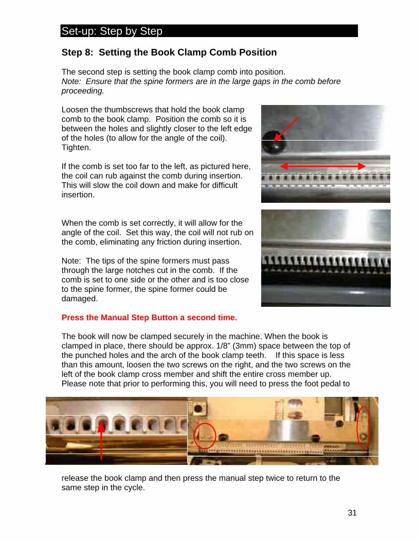
Step 8: Setting the Book Clamp Comb Position The second step is setting the book clamp comb into position. Note: Ensure that the spine formers are in the large gaps in the comb before proceeding. Loosen the thumbscrews that hold the book clamp comb to the book clamp. Position the comb so it is between the holes and slightly closer to the left edge of the holes (to allow for the angle of the coil). Tighten. If the comb is set too far to the left, as pictured here, the coil can rub against the comb during insertion. This will slow the coil down and make for difficult insertion. When the comb is set correctly, it will allow for the angle of the coil. Set this way, the coil will not rub on the comb, eliminating any friction during insertion. Note: The tips of the spine formers must pass through the large notches cut in the comb. If the comb is set to one side or the other and is too close to the spine former, the spine former could be damaged. Press the Manual Step Button a second time. The book will now be clamped securely in the machine. When the book is clamped in place, there should be approx. 1/8” (3mm) space between the top of the punched holes and the arch of the book clamp teeth. If this space is less than this amount, loosen the two screws on the right, and the two screws on the left of the book clamp cross member and shift the entire cross member up. Please note that prior to performing this, you will need to press the foot pedal to
release the book clamp and then press the manual step twice to return to the same step in the cycle.
Set-up: Step by Step
32
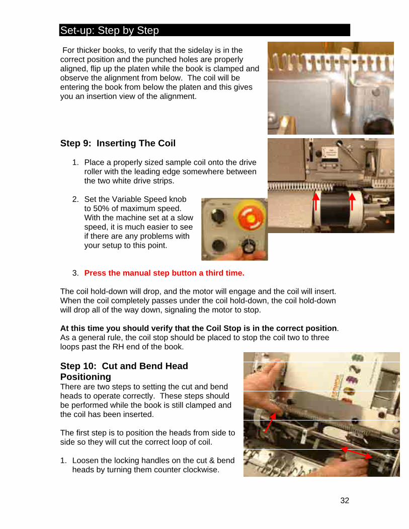
For thicker books, to verify that the sidelay is in the correct position and the punched holes are properly aligned, flip up the platen while the book is clamped and observe the alignment from below. The coil will be entering the book from below the platen and this gives you an insertion view of the alignment. Step 9: Inserting The Coil
1. Place a properly sized sample coil onto the drive roller with the leading edge somewhere between the two white drive strips.
2. Set the Variable Speed knob
to 50% of maximum speed. With the machine set at a slow speed, it is much easier to see if there are any problems with your setup to this point.
3. Press the manual step button a third time.
The coil hold-down will drop, and the motor will engage and the coil will insert. When the coil completely passes under the coil hold-down, the coil hold-down will drop all of the way down, signaling the motor to stop. At this time you should verify that the Coil Stop is in the correct position. As a general rule, the coil stop should be placed to stop the coil two to three loops past the RH end of the book. Step 10: Cut and Bend Head Positioning There are two steps to setting the cut and bend heads to operate correctly. These steps should be performed while the book is still clamped and the coil has been inserted. The first step is to position the heads from side to side so they will cut the correct loop of coil. 1. Loosen the locking handles on the cut & bend
heads by turning them counter clockwise.
Set-up: Step by Step
33
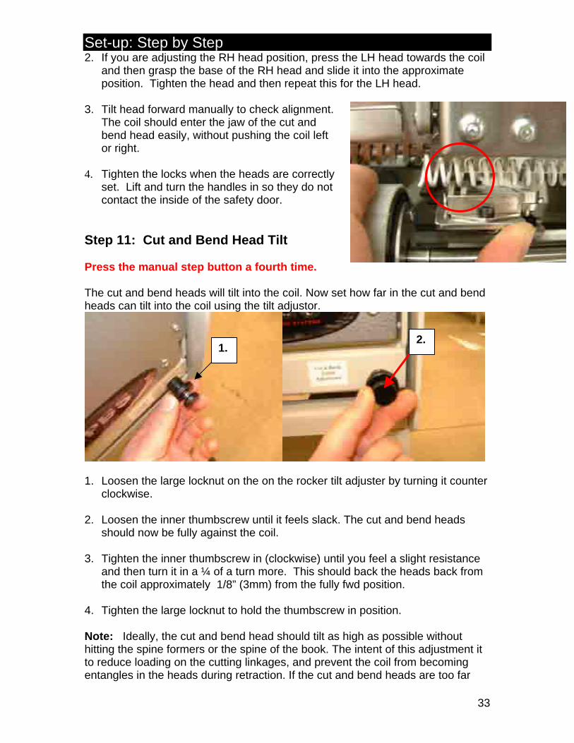
2. If you are adjusting the RH head position, press the LH head towards the coil and then grasp the base of the RH head and slide it into the approximate position. Tighten the head and then repeat this for the LH head.
3. Tilt head forward manually to check alignment.
The coil should enter the jaw of the cut and bend head easily, without pushing the coil left or right.
4. Tighten the locks when the heads are correctly
set. Lift and turn the handles in so they do not contact the inside of the safety door.
Step 11: Cut and Bend Head Tilt Press the manual step button a fourth time. The cut and bend heads will tilt into the coil. Now set how far in the cut and bend heads can tilt into the coil using the tilt adjustor.
1.
2.
1. Loosen the large locknut on the on the rocker tilt adjuster by turning it counter
clockwise. 2. Loosen the inner thumbscrew until it feels slack. The cut and bend heads
should now be fully against the coil. 3. Tighten the inner thumbscrew in (clockwise) until you feel a slight resistance
and then turn it in a ¼ of a turn more. This should back the heads back from the coil approximately 1/8” (3mm) from the fully fwd position.
4. Tighten the large locknut to hold the thumbscrew in position. Note: Ideally, the cut and bend head should tilt as high as possible without hitting the spine formers or the spine of the book. The intent of this adjustment it to reduce loading on the cutting linkages, and prevent the coil from becoming entangles in the heads during retraction. If the cut and bend heads are too far
Set-up: Step by Step
34
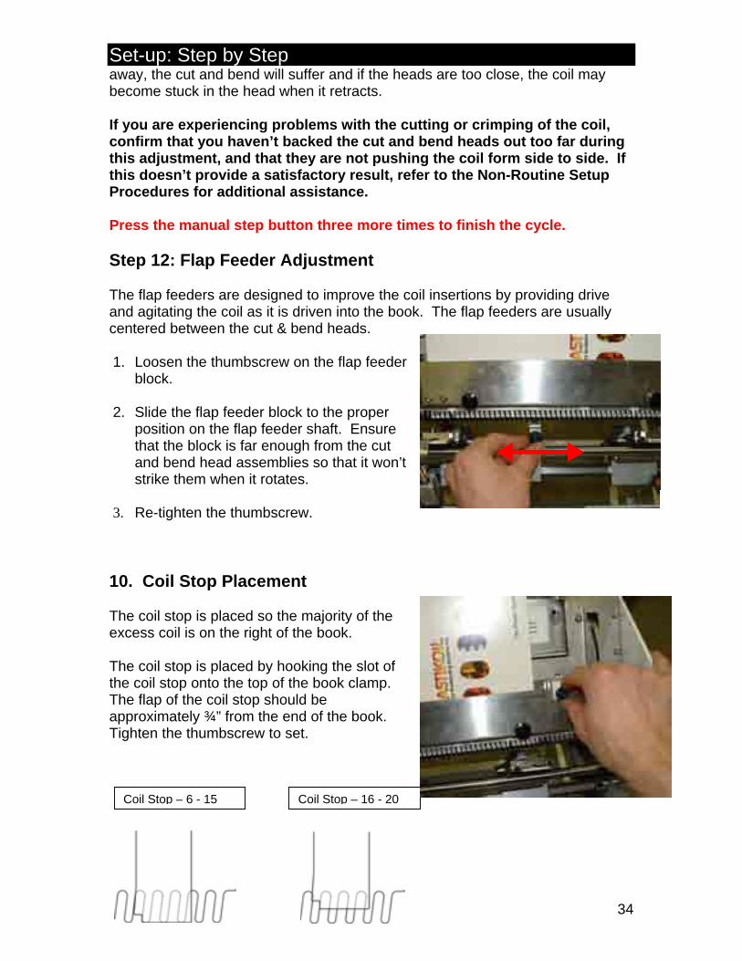
Coil Stop – 6 - 15 Coil Stop – 16 - 20
away, the cut and bend will suffer and if the heads are too close, the coil may become stuck in the head when it retracts. If you are experiencing problems with the cutting or crimping of the coil, confirm that you haven’t backed the cut and bend heads out too far during this adjustment, and that they are not pushing the coil form side to side. If this doesn’t provide a satisfactory result, refer to the Non-Routine Setup Procedures for additional assistance. Press the manual step button three more times to finish the cycle. Step 12: Flap Feeder Adjustment The flap feeders are designed to improve the coil insertions by providing drive and agitating the coil as it is driven into the book. The flap feeders are usually centered between the cut & bend heads. 1. Loosen the thumbscrew on the flap feeder
block. 2. Slide the flap feeder block to the proper
position on the flap feeder shaft. Ensure that the block is far enough from the cut and bend head assemblies so that it won’t strike them when it rotates.
3. Re-tighten the thumbscrew. 10. Coil Stop Placement The coil stop is placed so the majority of the excess coil is on the right of the book. The coil stop is placed by hooking the slot of the coil stop onto the top of the book clamp. The flap of the coil stop should be approximately ¾” from the end of the book. Tighten the thumbscrew to set.
Set-up: Step by Step
35
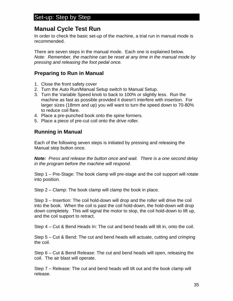
Manual Cycle Test Run In order to check the basic set-up of the machine, a trial run in manual mode is recommended. There are seven steps in the manual mode. Each one is explained below. Note: Remember, the machine can be reset at any time in the manual mode by pressing and releasing the foot pedal once. Preparing to Run in Manual 1. Close the front safety cover 2. Turn the Auto Run/Manual Setup switch to Manual Setup. 3. Turn the Variable Speed knob to back to 100% or slightly less. Run the
machine as fast as possible provided it doesn’t interfere with insertion. For larger sizes (18mm and up) you will want to turn the speed down to 70-80% to reduce coil flare.
4. Place a pre-punched book onto the spine formers. 5. Place a piece of pre-cut coil onto the drive roller. Running in Manual Each of the following seven steps is initiated by pressing and releasing the Manual step button once. Note: Press and release the button once and wait. There is a one second delay in the program before the machine will respond. Step 1 – Pre-Stage: The book clamp will pre-stage and the coil support will rotate into position. Step 2 – Clamp: The book clamp will clamp the book in place. Step 3 – Insertion: The coil hold-down will drop and the roller will drive the coil into the book. When the coil is past the coil hold-down, the hold-down will drop down completely. This will signal the motor to stop, the coil hold-down to lift up, and the coil support to retract. Step 4 – Cut & Bend Heads In: The cut and bend heads will tilt in, onto the coil. Step 5 – Cut & Bend: The cut and bend heads will actuate, cutting and crimping the coil. Step 6 – Cut & Bend Release: The cut and bend heads will open, releasing the coil. The air blast will operate. Step 7 – Release: The cut and bend heads will tilt out and the book clamp will release.
Set-up: Step by Step
36
Note: The safety cover can be opened at any time between steps of the manual cycle, allowing for any minor adjustments. It will freeze in the step it is in, and will not respond to the step button. The cover must be closed to continue. If the cover is opened during Step 3 while the roller is running, the motor will stop and the machine will return to Step 2. Close the cover and press the step button to go to Step 3 again. Automatic Operation Once the machine is set up and tested in manual mode, the machine can be run in automatic mode. The seven steps from manual operation are the same in automatic operation; only the machine does most of them automatically. The following six steps detail how to operate the machine in Auto Run mode. Step 1 - Turn Mode switch to Auto. The machine will automatically go to Step 1, or the Pre-stage, after ¾ of a second. Step 2 – Select the insertion speed by turning the Speed control up (clockwise) to the desired speed. This is usually 100, although it can be slower in some circumstances. Step 3 – Place the pre-punched book and pre-cut coil length into position (the
coil must be on the rubber roller). Caution: Crush Hazard – Keep hands away from the book clamp when operating the equipment. Caution: Roller Hazard – Keep hands away from the drive rollers when operating the equipment. Also keep hair, clothing, jewelry, or any other items that may be caught by the rollers. Note: Do not operate the equipment with any guards or safety shields
removed. Step 4 – Press and release the foot pedal once to initiate the cycle. Note: The machine will do steps 2 –7 (See ‘Running in Manual’) automatically. Step 5 – While the machine is inserting, pick up the next piece of coil. Drop it onto the roller as soon as the insertion portion of the cycle is done. Step 6 – Remove the bound book. The machine will automatically Pre-stage ¾ of a second after the end of the cycle. Repeat Steps 3 to 5. Note: The machine can be stopped at any point in the automatic cycle by pressing and releasing the foot pedal. This can be useful if there is some trouble with insertion (such as an improperly placed book). The program will reset. To re-start the cycle, simply press the foot pedal once after the machine has gone back to pre-stage.
Operating Tips:
37
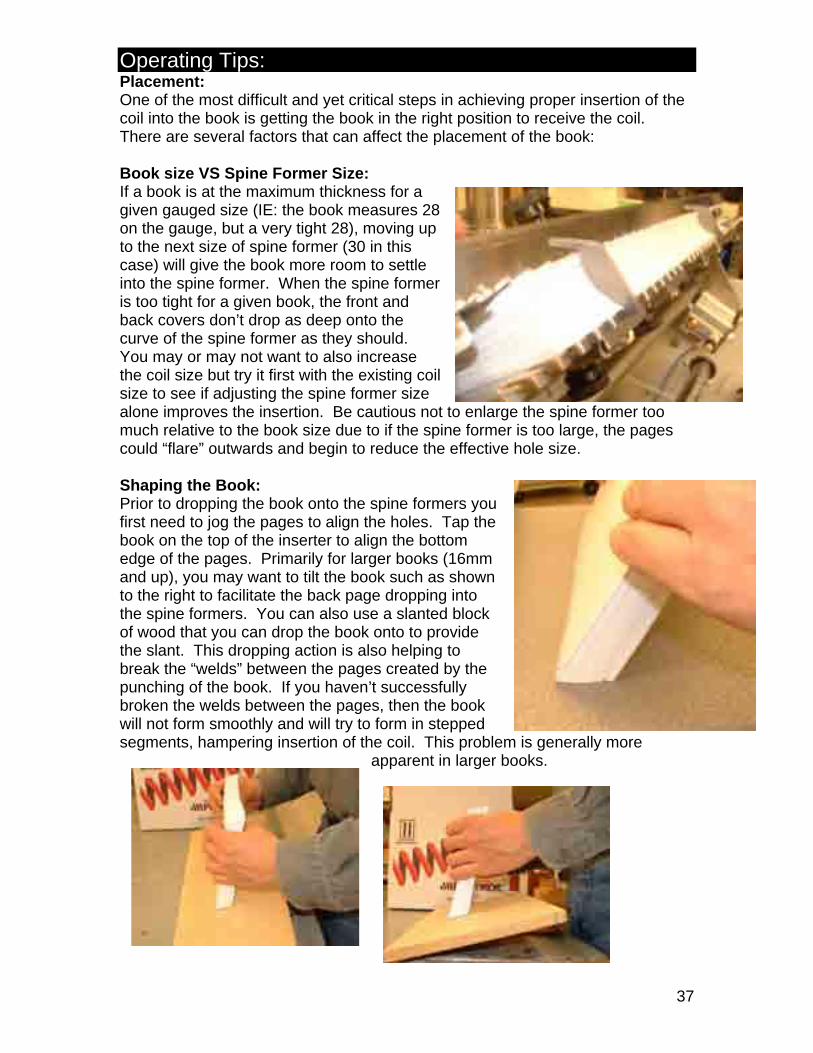
Placement: One of the most difficult and yet critical steps in achieving proper insertion of the coil into the book is getting the book in the right position to receive the coil. There are several factors that can affect the placement of the book: Book size VS Spine Former Size: If a book is at the maximum thickness for a given gauged size (IE: the book measures 28 on the gauge, but a very tight 28), moving up to the next size of spine former (30 in this case) will give the book more room to settle into the spine former. When the spine former is too tight for a given book, the front and back covers don’t drop as deep onto the curve of the spine former as they should. You may or may not want to also increase the coil size but try it first with the existing coil size to see if adjusting the spine former size alone improves the insertion. Be cautious not to enlarge the spine former too much relative to the book size due to if the spine former is too large, the pages could “flare” outwards and begin to reduce the effective hole size. Shaping the Book: Prior to dropping the book onto the spine formers you first need to jog the pages to align the holes. Tap the book on the top of the inserter to align the bottom edge of the pages. Primarily for larger books (16mm and up), you may want to tilt the book such as shown to the right to facilitate the back page dropping into the spine formers. You can also use a slanted block of wood that you can drop the book onto to provide the slant. This dropping action is also helping to break the “welds” between the pages created by the punching of the book. If you haven’t successfully broken the welds between the pages, then the book will not form smoothly and will try to form in stepped segments, hampering insertion of the coil. This problem is generally more
apparent in larger books.
Operating Tips:
38
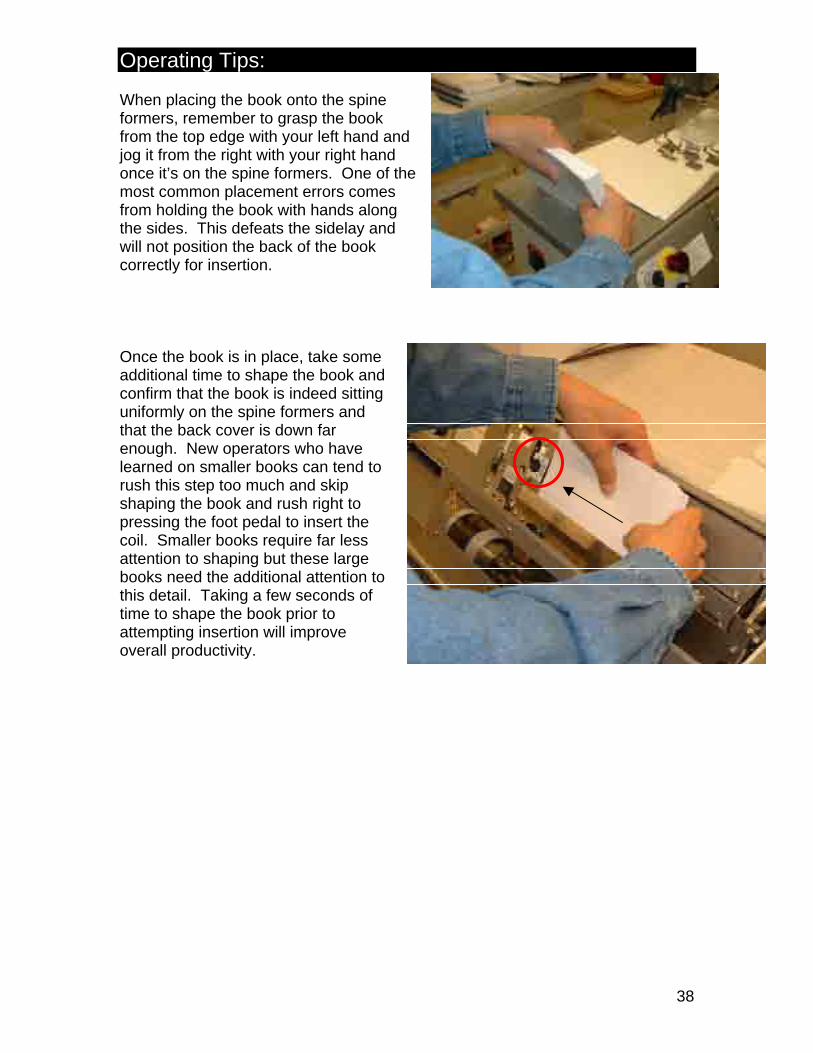
When placing the book onto the spine formers, remember to grasp the book from the top edge with your left hand and jog it from the right with your right hand once it’s on the spine formers. One of the most common placement errors comes from holding the book with hands along the sides. This defeats the sidelay and will not position the back of the book correctly for insertion. Once the book is in place, take some additional time to shape the book and confirm that the book is indeed sitting uniformly on the spine formers and that the back cover is down far enough. New operators who have learned on smaller books can tend to rush this step too much and skip shaping the book and rush right to pressing the foot pedal to insert the coil. Smaller books require far less attention to shaping but these large books need the additional attention to this detail. Taking a few seconds of time to shape the book prior to attempting insertion will improve overall productivity.
Operating Tips:
39
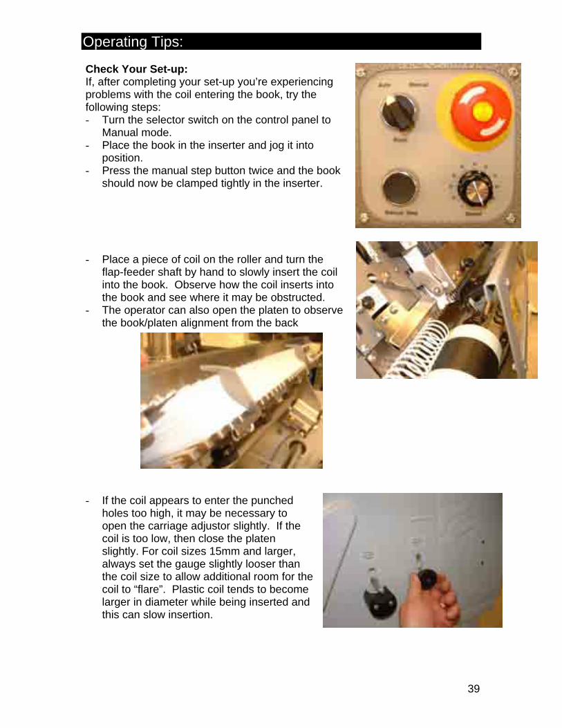
Check Your Set-up: If, after completing your set-up you’re experiencing problems with the coil entering the book, try the following steps: - Turn the selector switch on the control panel to
Manual mode. - Place the book in the inserter and jog it into
position. - Press the manual step button twice and the book
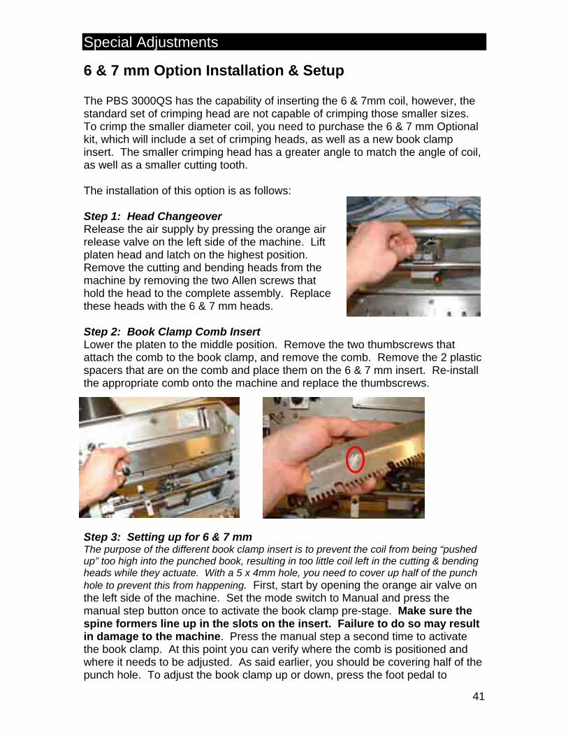
should now be clamped tightly in the inserter. - Place a piece of coil on the roller and turn the
flap-feeder shaft by hand to slowly insert the coil into the book. Observe how the coil inserts into the book and see where it may be obstructed.
- The operator can also open the platen to observe the book/platen alignment from the back
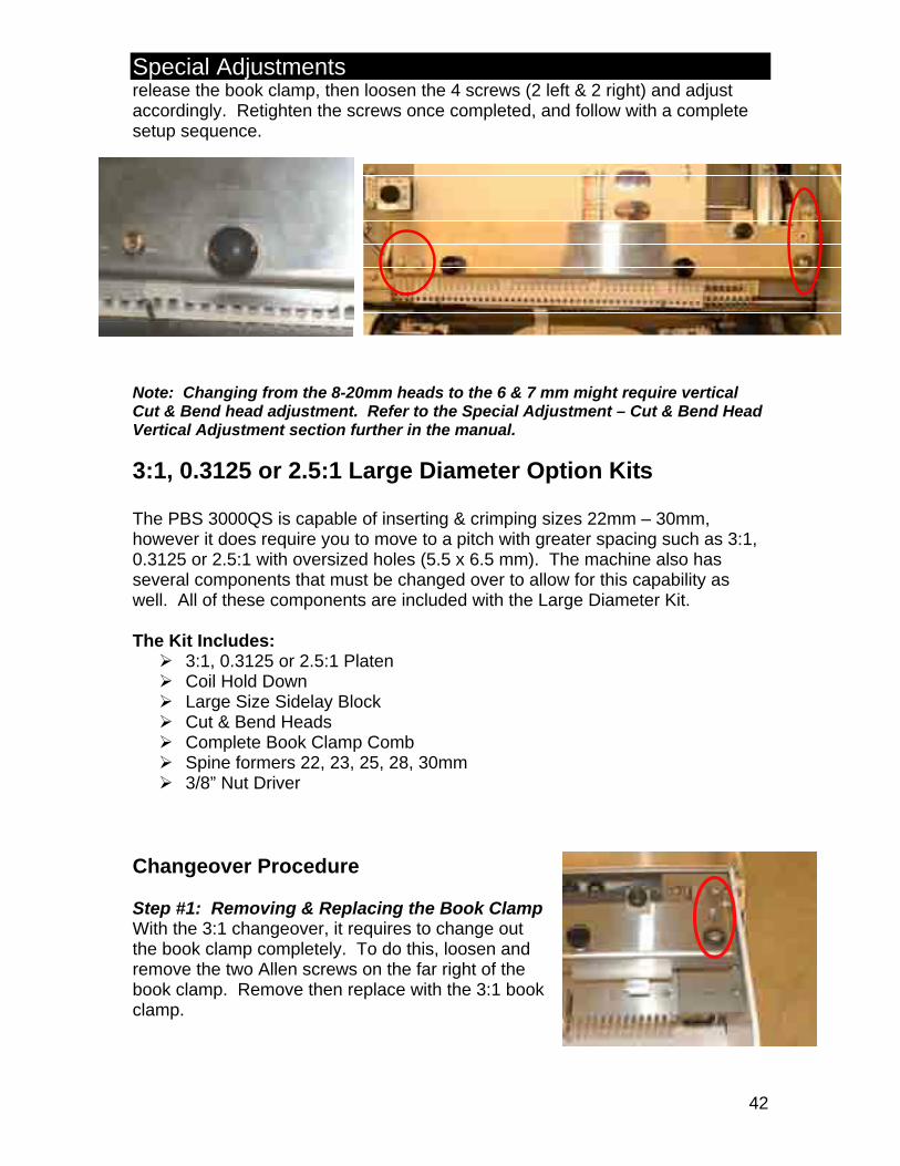
- If the coil appears to enter the punched
holes too high, it may be necessary to open the carriage adjustor slightly. If the coil is too low, then close the platen slightly. For coil sizes 15mm and larger, always set the gauge slightly looser than the coil size to allow additional room for the coil to “flare”. Plastic coil tends to become larger in diameter while being inserted and this can slow insertion.

Operating Tips:
40
Reduce the speed of the drive roller: Trying to drive a large coil too aggressively into the book can cause it to bounce around and miss the book entirely. When you get to coil sizes 16mm and up, turn the speed down to 70% and see if this improves insertion. For smaller sizes, run the inserter as fast as possible without causing insertion or consistency problems. Reduce the Pressure on the Coil: The coil requires very little pressure to drive it through the book and generally too much pressure on the coil will cause it to expand and reduce the insertion speed. Use only medium to light pressure on the coil. Stop and Start: When the coil gets only partially through the book, stops or slows, or if it struggles to start into the first hole of the book, these are indications that the book is likely not in the correct position. The book needs reshaping or repositioning. Quickly hit the foot pedal to stop the insertion cycle. This does two things:
1) It releases the book to allow it to be reshaped and to allow the coil to shape the book just like you would when manually inserting the coil.
2) The coil relaxes and returns to its proper size. When plastic spiral meets resistance in the holes of the book, the coil flares (becomes larger in diameter) and hits the tops of the punched holes.
The strength of the PBS3000QS is that you can stop and start the insertion at any time during the insertion cycle and reposition the book and start again. This is particularly advantageous in books with inserts or pages that are difficult to align. Allowing the machine to continue to struggle with a misaligned large book slows the productivity of the machine and tends to result in the coil not being cut and crimped correctly on the ends.
Special Adjustments
41
6 & 7 mm Option Installation & Setup The PBS 3000QS has the capability of inserting the 6 & 7mm coil, however, the standard set of crimping head are not capable of crimping those smaller sizes. To crimp the smaller diameter coil, you need to purchase the 6 & 7 mm Optional kit, which will include a set of crimping heads, as well as a new book clamp insert. The smaller crimping head has a greater angle to match the angle of coil, as well as a smaller cutting tooth. The installation of this option is as follows: Step 1: Head Changeover Release the air supply by pressing the orange air release valve on the left side of the machine. Lift platen head and latch on the highest position. Remove the cutting and bending heads from the machine by removing the two Allen screws that hold the head to the complete assembly. Replace these heads with the 6 & 7 mm heads. Step 2: Book Clamp Comb Insert Lower the platen to the middle position. Remove the two thumbscrews that attach the comb to the book clamp, and remove the comb. Remove the 2 plastic spacers that are on the comb and place them on the 6 & 7 mm insert. Re-install the appropriate comb onto the machine and replace the thumbscrews.
Step 3: Setting up for 6 & 7 mm The purpose of the different book clamp insert is to prevent the coil from being “pushed up” too high into the punched book, resulting in too little coil left in the cutting & bending heads while they actuate. With a 5 x 4mm hole, you need to cover up half of the punch hole to prevent this from happening. First, start by opening the orange air valve on the left side of the machine. Set the mode switch to Manual and press the manual step button once to activate the book clamp pre-stage. Make sure the spine formers line up in the slots on the insert. Failure to do so may result in damage to the machine. Press the manual step a second time to activate the book clamp. At this point you can verify where the comb is positioned and where it needs to be adjusted. As said earlier, you should be covering half of the punch hole. To adjust the book clamp up or down, press the foot pedal to
Special Adjustments
42
release the book clamp, then loosen the 4 screws (2 left & 2 right) and adjust accordingly. Retighten the screws once completed, and follow with a complete setup sequence.
Note: Changing from the 8-20mm heads to the 6 & 7 mm might require vertical Cut & Bend head adjustment. Refer to the Special Adjustment – Cut & Bend Head Vertical Adjustment section further in the manual.
3:1, 0.3125 or 2.5:1 Large Diameter Option Kits The PBS 3000QS is capable of inserting & crimping sizes 22mm – 30mm, however it does require you to move to a pitch with greater spacing such as 3:1, 0.3125 or 2.5:1 with oversized holes (5.5 x 6.5 mm). The machine also has several components that must be changed over to allow for this capability as well. All of these components are included with the Large Diameter Kit. The Kit Includes:
3:1, 0.3125 or 2.5:1 Platen Coil Hold Down Large Size Sidelay Block Cut & Bend Heads Complete Book Clamp Comb Spine formers 22, 23, 25, 28, 30mm 3/8” Nut Driver
Changeover Procedure Step #1: Removing & Replacing the Book Clamp With the 3:1 changeover, it requires to change out the book clamp completely. To do this, loosen and remove the two Allen screws on the far right of the book clamp. Remove then replace with the 3:1 book clamp.

Special Adjustments
43
Step #2: Removing & Replacing the Platen Insert To remove the platen insert, start by removing the two Allen screws located near the Coil Hold Down. Then lift the platen and latch to the highest position. With a 3/8” Nut driver, loosen the 4 nuts (6 for the 17” version) and slide the platen insert out, then replace with the oversize kit platen insert. Before tightening the new insert into position, make sure that the platen is level. This can be verified by lining up the right edge of the insert with the platen and then replacing the two Allen screws (do not tighten yet). Once the insert is properly aligned, retighten the nuts and then tighten the two screws.
Step #3 – Changing the Cutting & Bending Heads With the platen still in its highest position, you must now change the cutting & bending heads. Release the air supply by pressing the orange air release valve on the left side of the machine. Remove the cutting and bending heads from the machine by removing the two Allen screws that hold the head to the complete assembly. Replace these heads with the heads etched 3:1. Note: The 3:1 heads are used for all large diameter kits regardless of pitch. Step #4 – Changing the Coil Hold Down Remove the two Allen screws that fasten the coil hold down to the block and replace with the coil hold down stamped 3:1. This coil hold down will apply pressure against the coil at an ideal position for the larger sizes.
The insert should line up with the platen
Special Adjustments
44
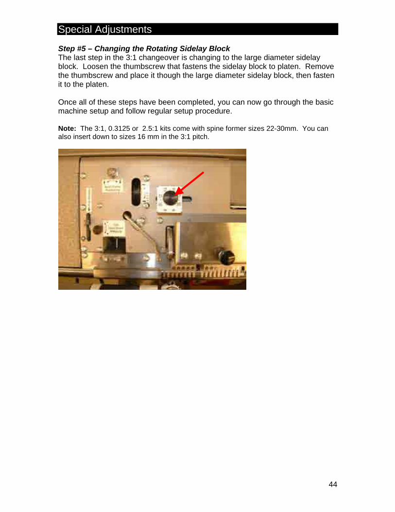
Step #5 – Changing the Rotating Sidelay Block The last step in the 3:1 changeover is changing to the large diameter sidelay block. Loosen the thumbscrew that fastens the sidelay block to platen. Remove the thumbscrew and place it though the large diameter sidelay block, then fasten it to the platen. Once all of these steps have been completed, you can now go through the basic machine setup and follow regular setup procedure. Note: The 3:1, 0.3125 or 2.5:1 kits come with spine former sizes 22-30mm. You can also insert down to sizes 16 mm in the 3:1 pitch.

Special Adjustments (Non Routine)
45
Cut and Bend Head Vertical Adjustment CUT & BEND HAZARD – A pinch/cutting hazard exists at the cut and bend heads. Disconnect the air supply when adjusting or servicing the cut & bend assembly. There may be times where you experience problems with your cut and/or crimp. In cases like these, the heads will need to be adjusted vertically. NOTE: Always confirm you have properly set-up the machine before assuming the head height needs adjustment. This adjustment is rarely required. There are two moving parts on a cut and bend head, shown here removed from the machine for clarity. (Crimping heads on the PBS 3000QS are slight different than picture)
2
1
1. Clamp tooth – The clamp tooth (number 1
above) clamps the coil into place as the jaws start to close.
2. Cut tooth - The cut tooth (number 2 above) cuts the coil, then bends it over the inside clamp tooth, giving the coil its crimp (as pictured above).
3. As this diagram illustrates, the smaller the coil diameter, the more precise a setup is required.
4. Generally, if the cut & bend height is set using an 8mm coil then the cut and bend height will not need to be adjusted for the larger sizes.

Special Adjustments (Non Routine)
46
With this head, the two problems that can occur are: 1. The coil will cut, but not crimp. 2. The coil will crimp but not cut. Table 1 details the problems and likely solutions. In order to have the crimp turn in on both ends of the book, the cut and bend heads are ‘mirror images’ of each other. Essentially, this means that the cut tooth is on the top on the left side and on the bottom on the right side (right side pictured below). This means that the same problem on both heads will mean that each head will need an adjustment, but not the same adjustment. The chart below is a general guideline.
Table 1 Cut and Bend Head Problem Suggested Solution
Right Crimping, not cutting Raise head Right Cutting, not crimping Lower head Left Crimping, not cutting Lower head Left Cutting, not crimping Raise head
Adjustment of the cut and bend heads is accomplished using the following procedure:
1. Using a 1/8” Allen key, loosen the 2 Allen screws on the handle side of the cut and bend head mount.
2. Using the same 1/8” key, adjust the cut and bend
head height screw on the top of the mount using half turn increments. Thread the head up (clockwise) or down (counter-clockwise) as required.
3. Tighten the cut and bend head fastening screws.
4. Test the new settings. If still unsatisfactory, adjust the height another half turn and retest. Repeat as necessary. Note: The goal is to produce the best, repeatable crimp for a given coil size. You may want to soften the crimp if you find that it leads to the cut and bend heads sometimes missing a crimp entirely.
Generally, once the heads have been set properly for 8mm coil, there is no further need to adjust them. Most cutting problems with larger diameter coil can be dealt with using the rocker tilt adjuster.
1
2
Special Adjustments (Non Routine)
47
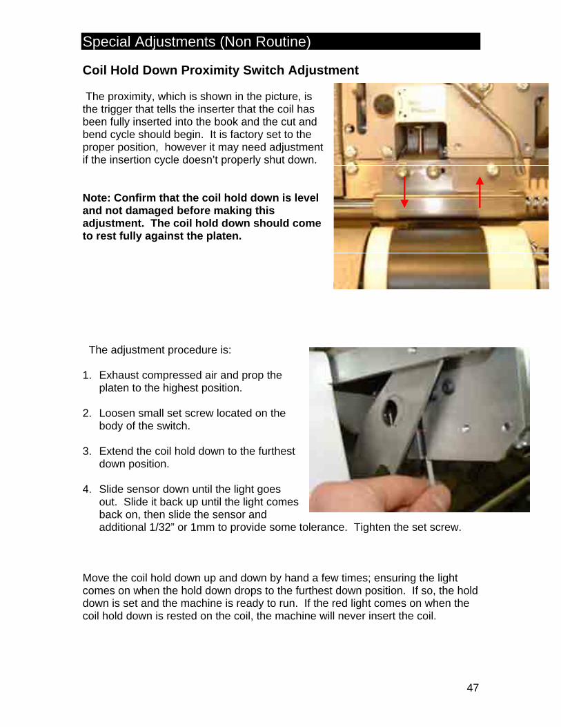
Coil Hold Down Proximity Switch Adjustment The proximity, which is shown in the picture, is the trigger that tells the inserter that the coil has been fully inserted into the book and the cut and bend cycle should begin. It is factory set to the proper position, however it may need adjustment if the insertion cycle doesn’t properly shut down. Note: Confirm that the coil hold down is level and not damaged before making this adjustment. The coil hold down should come to rest fully against the platen. The adjustment procedure is: 1. Exhaust compressed air and prop the
platen to the highest position. 2. Loosen small set screw located on the
body of the switch. 3. Extend the coil hold down to the furthest
down position. 4. Slide sensor down until the light goes
out. Slide it back up until the light comes back on, then slide the sensor and additional 1/32” or 1mm to provide some tolerance. Tighten the set screw.
Move the coil hold down up and down by hand a few times; ensuring the light comes on when the hold down drops to the furthest down position. If so, the hold down is set and the machine is ready to run. If the red light comes on when the coil hold down is rested on the coil, the machine will never insert the coil.

Special Adjustments (Non Routine)
48
Spine Former Profile And Platen Height: During use of the inserter, the spine formers can be bent or damaged. Prior to the start of each shift, or when the insertion of the coil into the book seems to have become more difficult, inspect the spine formers to be certain they have not become damaged. Grasp the book clamp and lift up the platen to inspect the steel roller shaft that runs behind the platen. Check for grooves that indicate that the spine former has come in contact with the steel roller. Check the left and right spine formers against one another to confirm that they of the same or similar shape. Inspect the backs of the spine formers to ensure that there is no signs of wear indicating they were in contact with the steel shaft.

Special Adjustments (Non Routine)
49
Adjustment of Platen Height: On each end of the platen, you will find a platen height adjustment screw recessed in the platen. To begin, use an 1/8” hex wrench to loosen both screws (turn them counter clockwise) until the platen is in contact with the steel roller beneath the teeth of the platen comb .
Once the platen is in contact with the steel roller, slowly tighten the left hand adjuster screw until you can slip a 0.015-0.020” (0.38 - 0.50mm) feeler gauge between platen comb and the steel roller as pictured. If you do not have a feeler gauge, a reasonably heavy cardstock book cover will also do nicely. Once you’ve successfully adjusted the LH side, slide the feeler gauge to the right hand end of the platen and adjust the screw on that end so that it just starts to lift the platen (IE. So that you know it’s also in contact with the adjustor stop). You may find that due to manufacturing tolerances, you are not able to get both ends of the platen to the same gap but this is not an issue (you may find this more apparent on inserters with a 17” binding edge). Simply ensure that the minimum gap between the steel roller and comb, when measured at any point, is no less than 0.015”. With the platen properly adjusted, insert a set of spine formers and close the platen. Confirm that the spine formers do not contact the steel roller when placed in any of the mounting blocks. If they do contact, confirm that they are not damaged, and then if not, slightly increase the platen height adjustment first at the left and then the right as before until the spine formers clear the steel roller. You should be able to slip two pages of 20lb bond paper behind the spine former.
Special Adjustments (Non Routine)
50
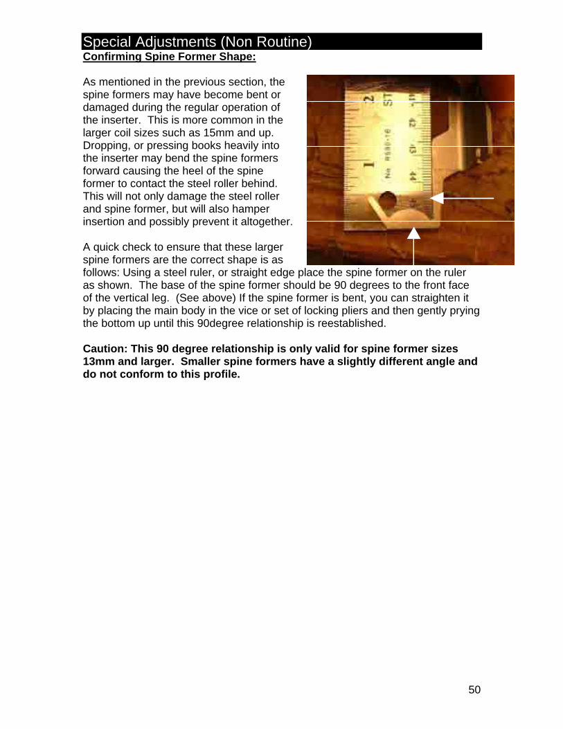
Confirming Spine Former Shape: As mentioned in the previous section, the spine formers may have become bent or damaged during the regular operation of the inserter. This is more common in the larger coil sizes such as 15mm and up. Dropping, or pressing books heavily into the inserter may bend the spine formers forward causing the heel of the spine former to contact the steel roller behind. This will not only damage the steel roller and spine former, but will also hamper insertion and possibly prevent it altogether. A quick check to ensure that these larger spine formers are the correct shape is as follows: Using a steel ruler, or straight edge place the spine former on the ruler as shown. The base of the spine former should be 90 degrees to the front face of the vertical leg. (See above) If the spine former is bent, you can straighten it by placing the main body in the vice or set of locking pliers and then gently prying the bottom up until this 90degree relationship is reestablished. Caution: This 90 degree relationship is only valid for spine former sizes 13mm and larger. Smaller spine formers have a slightly different angle and do not conform to this profile.
General Maintenance
51
Basic Machine Maintenance Consult the PBS3000QS Parts and Service Manual supplied with the inserter for more extensive service tips and information. On a routine basis, perform the following daily maintenance:
1. The PBS 3000QS should be kept clean and free of dust and debris. Paper dust can cause machine mechanisms to stick, particularly the coil hold down. Remove any residual coil off-cuts that may be lodged in the machine.
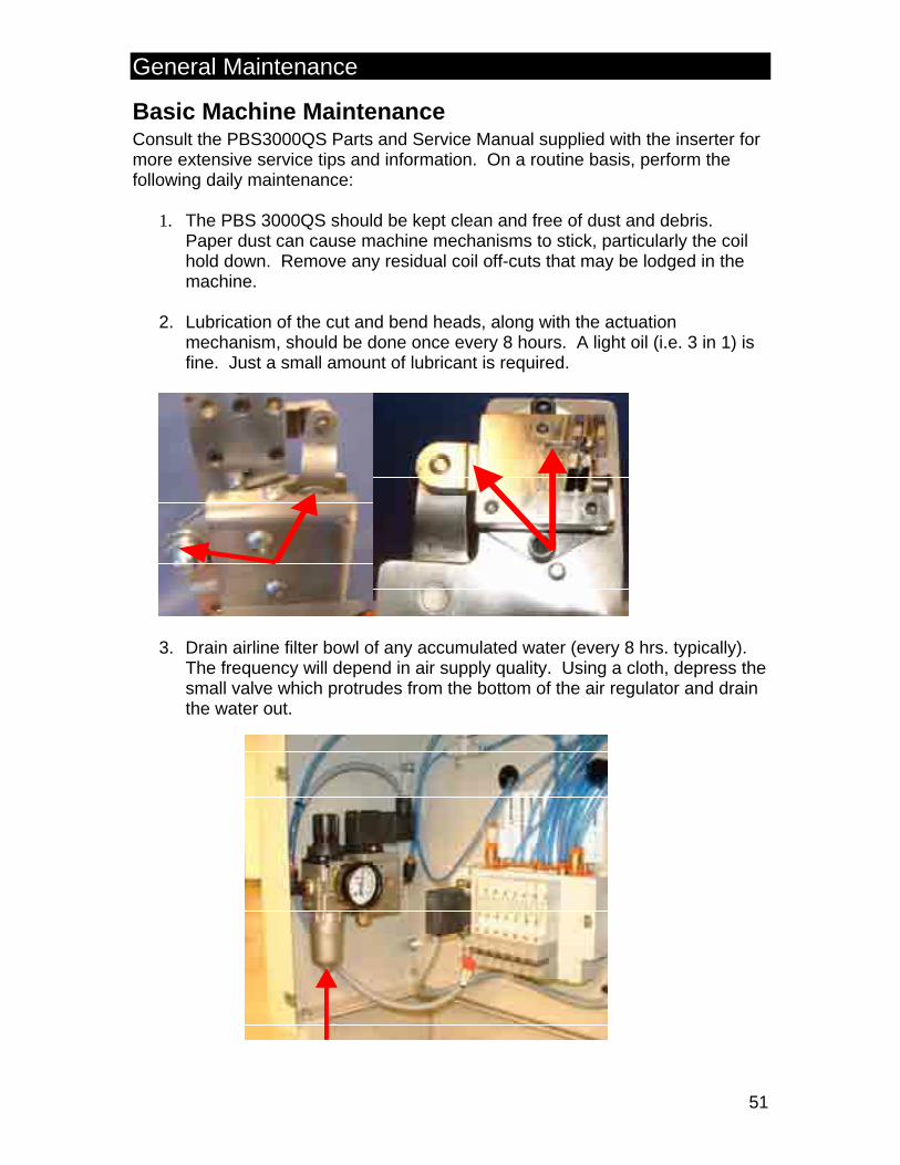
2. Lubrication of the cut and bend heads, along with the actuation
mechanism, should be done once every 8 hours. A light oil (i.e. 3 in 1) is fine. Just a small amount of lubricant is required.
3. Drain airline filter bowl of any accumulated water (every 8 hrs. typically). The frequency will depend in air supply quality. Using a cloth, depress the small valve which protrudes from the bottom of the air regulator and drain the water out.

Troubleshooting
52
Troubleshooting Common PBS 3000QS Problems Symptom – Coil inserts but motor does not disengage and allow cut and bend heads to activate. Possible Solutions - 1. Ensure that the coil hold down is dropping completely. If the mechanism is
clogged with dust or dirt, bent, or if the tubing behind the platen becomes tangled in the magnet plate, it may not drop all the way. Stop the cycle, exhaust the air from the machine, and ensure that the coil hold down is moving freely.
2. The proximity switch in the coil hold down may need adjustment. See ‘Coil
Hold Down Proximity Switch Adjustment’ in the Special Adjustments section. Symptom – Poor quality cut and bend. Possible Solutions – 1. Ensure the cut and bend heads are tilting in far enough. See ‘Cut and Bend
Head Positioning’ in the Step by Step Set-up section. 2. The cut and bend heads may be out of vertical alignment. See ‘Cut and Bend
Head Vertical Adjustment’ in the Special Adjustments section. Symptom – Coil inserts part way into the book, but insertion seems very slow. Possible Solutions – 1. Double-check the punch quality of the book. Ensure that the punched holes
are clean and registered. 2. Re-check the book’s positioning. Ensure that all the book’s components are
in position on the spine formers, jogged tight to the sidelay, and laying flat. 3. Check the coil quality. 4. Check for offcut debris. 5. Check the book clamp comb to see if it is rubbing against the coil during
insertion,

Troubleshooting
53
Symptom – The coil is not finding its way into the first punched hole in automatic mode, even though all the adjustments seem correct. Possible Solutions – 1. Check the coil for bent or damaged ends. 2. Check for offcut debris lodged in the machine. 3. Check punching quality & consistency. Symptom – Coil bounces back after insertion and misses the right cut & bend head. Possible solutions - 1. Adjust coil stop. 2. Slow insertion speed. For all other questions, please contact your local representative or in North America call: Gateway Bookbinding Systems Ltd. Toll free 1-800-665-7884 (in North America) Ph. (204) 663-9214 (international) Fax (204) 663-7905 E-mail: [email protected]
54
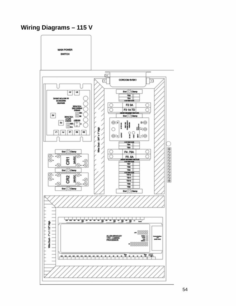
Wiring Diagrams – 115 V

55
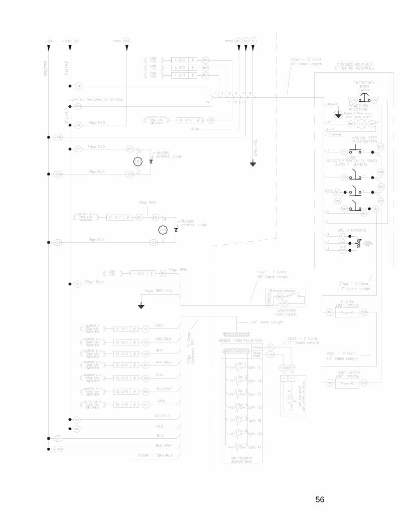
56

57
Wiring Diagrams – 230V

58

59
60
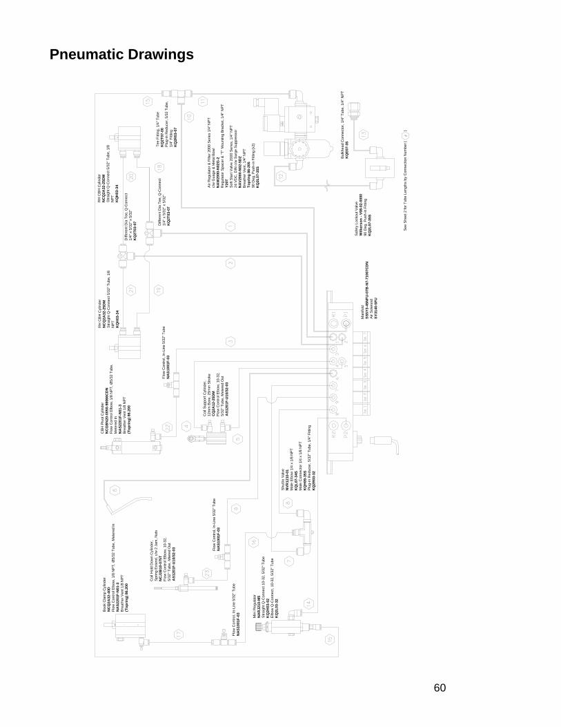
Pneumatic Drawings
Diff
eren
t Dia
Tee
, Q-C
onne
ct
1/4"
x 5
/32"
x 5
/32"
K
Q2T
03-0
7
Diff
eren
t Dia
Tee
, Q-C
onne
ct
1/4"
x 5
/32"
x 5
/32"
K
Q2T
03-0
7
Flow
Con
trol,
In-L
ine
5/32
" Tub
eN
AS1
001F
-03
Flow
Con
trol,
In-L
ine
5/32
" Tub
eN
AS1
001F
-03
Flow
Con
trol,
In-L
ine
5/32
" Tub
eN
AS1
001F
-03
See
She
et 2
for T
ube
Leng
ths
by C
onne
ctio
n N
umbe
r (
)
RH
CB
H C
ylin
der
NC
Q2A
32-2
5DM
Stra
ight
Q-C
onne
ct 5
/32"
Tub
e, 1
/8
NPT
K
QH
03-3
4
Shu
ttle
Valv
eN
VR12
10-0
1M
ale
Elbo
w 1
/4 x
1/8
NPT
KQ
L07-
34S
Mal
e C
onne
ctor
1/4
x 1
/8 N
PTK
QH
09-3
5SPl
ug-in
Red
ucer
, 5/3
2" T
ube,
1/4
" Fitt
ing
KQ
2R03
-32
Bul
khea
d C
onne
ctor
, 1/4
" Tub
e, 1
/4" N
PTK
QE0
7-35
Safe
ty L
ocko
ut V
alve
Wilk
erso
n - V
08-0
2-00
0090
Deg
. Pus
h-in
Fitt
ing
KQ
2L07
-35S
Air R
egul
ator
& F
ilter
200
0 Se
ries
1/4"
NPT
c/w
Gua
ge &
Met
al B
owl
NA
W20
00-N
02G
-2R
egul
ator
Spa
cer &
"T" M
ount
ing
Brac
ket,
1/4"
NPT
Y20T
Soft
Sta
rt V
alve
200
0 Se
ries,
1/4
" NPT
24 V
DC
, DIN
c/w
Sur
ge S
uppr
esso
rN
AV2
000-
N02
-5D
ZB
reat
her V
ent,
1/4"
NPT
Topr
ing
86-2
0590
Deg
. Pus
h-in
Fitt
ing
(x2)
KQ
2L07
-35S
Tee
Fitti
ng, 1
/4" T
ube
KQ
2T07
-00
Plug
-in R
educ
er, 5
/32
Tube
, 1/
4" F
ittin
g K
Q2R
03-0
7
Min
i Reg
ulat
orN
AR
J210
-M5
Stra
ight
Q-C
onne
ct 1
0-32
, 5/3
2" T
ube
KQ
2H03
-02
Elb
ow Q
-Con
nect
, 10-
32, 5
/32"
Tub
eK
Q2L
03-3
2
CBH
Piv
ot C
ylin
der
NC
GB
N20
-005
0-98
066C
DN
Flow
Con
trol E
lbow
, 1/8
NPT
, Ø5/
32 T
ube,
M
eter
ed In
NA
S220
1F-N
01-3
Bre
athe
r Ven
t 1/8
NPT
(Top
ring)
86.
200
Boo
k C
lam
p C
ylin
der
NC
Q2A
32-4
0DFl
ow C
ontro
l Elb
ow, 1
/8 N
PT, Ø
5/32
Tub
e, M
eter
ed In
NA
S220
1F-N
01-3
Bre
athe
r Ven
t 1/8
NPT
(Top
ring)
86.
200
Man
ifold
SS5Y
3-45
NFU
-07B
-N7-
7100
7CD
NAi
r Sol
enoi
dSY
3140
-5FU
RH
CB
H C
ylin
der
NC
Q2A
32-2
5DM
Stra
ight
Q-C
onne
ct 5
/32"
Tub
e, 1
/8
NPT
K
QH
03-3
4
Coi
l Sup
port
Cyl
inde
r, 12
mm
Bor
e, 2
5mm
Stro
keC
Q2A
12-2
5DM
Flow
Con
trol E
lbow
, 10-
32,
5/32
" Tub
e, M
eter
ed O
utA
S120
1F-U
10/3
2-03
Coi
l Hol
d D
own
Cyl
inde
r, S
prin
g Ex
tend
, c/w
2 J
am, N
uts
NC
J2B
10-0
75T
Flow
Con
trol E
lbow
, 10-
32,
5/32
" Tub
e, M
tere
d O
utA
S120
1F-U
10/3
2-03

61
12" 17"
1 & 1/4 12" 12"2 & 1/4 12" 12"3 & 5/32 15 1/2" 15 1/2"4 & 5/32 36" 36"5 & 5/32 36" 36"6 & 1/4 20" 20"7 & 5/32 11 3/4" 11 3/4"8 & 5/32 9 3/4" 9 3/4"9 & 5/32 21" 32"10 & 1/4 5 1/2" 5 1/2"11 & 1/4 14" 14"12 & 1/4 47 1/2" 47 1/2"13 & 1/4 7" 7"14 & 5/32 27" 31"15 & 5/32 17" 17"16 & 5/32 16" 16"17 & 5/32 7" 7"18 & 5/32 18" 18"19 & 5/32 15" 15"20 & 5/32 18" 18"21 & 5/32 15" 15"22 & 5/32 6" 6"23 & 5/32 6" 6"
140033140035
Number Tubing Dia Tubing Length
Polyurethane Tube 5/32 Polyurethane Tube 1/4"


![SKF solutions for printing, bindery, finishing, converting ... · PDF fileSKF solutions for printing, bindery, finishing, converting and packaging machinery ; _ j ] : ; bergab@ya.ru](https://static.fdocuments.in/doc/165x107/5aa87d137f8b9a95188b9bfb/skf-solutions-for-printing-bindery-finishing-converting-solutions-for-printing.jpg)