PBR PBU Panels - A&S
36
PBR & PBU Panels Design/Installation Information
Transcript of PBR PBU Panels - A&S

PBR & PBU Panels Design/Installation Information

SUBJECT TO CHANGE WITHOUT NOTICE EFFECTIVE FEBRUARY 10, 2014 1
TABLE OF CONTENTSA. PBR Panel
1. General Description . . . . . . . . . . . . . . . . . . . . . . . . . . . . . . . . . . . . . . . . . . . . . . . . . . . . . . . . . . . . . . 22. Architect/Engineer Information. . . . . . . . . . . . . . . . . . . . . . . . . . . . . . . . . . . . . . . . . . . . . . . . . . . . . . 23. Product Selection Chart . . . . . . . . . . . . . . . . . . . . . . . . . . . . . . . . . . . . . . . . . . . . . . . . . . . . . . . . . . 24. Factory Mutual Approvals . . . . . . . . . . . . . . . . . . . . . . . . . . . . . . . . . . . . . . . . . . . . . . . . . . . . . . . . . 25. PBR Panel Section Properties. . . . . . . . . . . . . . . . . . . . . . . . . . . . . . . . . . . . . . . . . . . . . . . . . . . . . . 36. PBR Panel Fastener Locations . . . . . . . . . . . . . . . . . . . . . . . . . . . . . . . . . . . . . . . . . . . . . . . . . . . . . 37. PBR Panel Allowable Uniform Roof Loads . . . . . . . . . . . . . . . . . . . . . . . . . . . . . . . . . . . . . . . . . . . . 48. PBR Panel Allowable Uniform Wall Loads. . . . . . . . . . . . . . . . . . . . . . . . . . . . . . . . . . . . . . . . . . . . . 59. PBR Panel UL 90 Requirements . . . . . . . . . . . . . . . . . . . . . . . . . . . . . . . . . . . . . . . . . . . . . . . . . . . . 610. PBR Panel Product Checklist . . . . . . . . . . . . . . . . . . . . . . . . . . . . . . . . . . . . . . . . . . . . . . . . . . . . 7-811. PBR Panel Attachment . . . . . . . . . . . . . . . . . . . . . . . . . . . . . . . . . . . . . . . . . . . . . . . . . . . . . . . . . . . 912. PBR Panel UL 90 Light Transmitting Panel Installation. . . . . . . . . . . . . . . . . . . . . . . . . . . . . . . 10-11
B. PBU Panel1. General Description . . . . . . . . . . . . . . . . . . . . . . . . . . . . . . . . . . . . . . . . . . . . . . . . . . . . . . . . . . . . . 122. Architect/Engineer Information. . . . . . . . . . . . . . . . . . . . . . . . . . . . . . . . . . . . . . . . . . . . . . . . . . . . . 123. Product Selection Chart . . . . . . . . . . . . . . . . . . . . . . . . . . . . . . . . . . . . . . . . . . . . . . . . . . . . . . . . . . 124. PBU Panel Section Properties. . . . . . . . . . . . . . . . . . . . . . . . . . . . . . . . . . . . . . . . . . . . . . . . . . . . . 135. PBU Panel Fastener Locations . . . . . . . . . . . . . . . . . . . . . . . . . . . . . . . . . . . . . . . . . . . . . . . . . . . . 136. PBR Panel Allowable Uniform Roof Loads . . . . . . . . . . . . . . . . . . . . . . . . . . . . . . . . . . . . . . . . . . . 147. PBR Panel Allowable Uniform Wall Loads. . . . . . . . . . . . . . . . . . . . . . . . . . . . . . . . . . . . . . . . . . . . 158. PBU Panel UL 90 Requirements . . . . . . . . . . . . . . . . . . . . . . . . . . . . . . . . . . . . . . . . . . . . . . . . . . . 169. PBU Panel Product Checklist . . . . . . . . . . . . . . . . . . . . . . . . . . . . . . . . . . . . . . . . . . . . . . . . . . 17-1810. PBU Panel Attachment . . . . . . . . . . . . . . . . . . . . . . . . . . . . . . . . . . . . . . . . . . . . . . . . . . . . . . . . . . 1911. PBU Panel Light Transmitting Panel Installation . . . . . . . . . . . . . . . . . . . . . . . . . . . . . . . . . . . . 20-21
C. Typical Details1. Ridge . . . . . . . . . . . . . . . . . . . . . . . . . . . . . . . . . . . . . . . . . . . . . . . . . . . . . . . . . . . . . . . . . . . . . . . . 222. High Side Eave . . . . . . . . . . . . . . . . . . . . . . . . . . . . . . . . . . . . . . . . . . . . . . . . . . . . . . . . . . . . . . . . 233. Hip . . . . . . . . . . . . . . . . . . . . . . . . . . . . . . . . . . . . . . . . . . . . . . . . . . . . . . . . . . . . . . . . . . . . . . . . . . 244. Valley . . . . . . . . . . . . . . . . . . . . . . . . . . . . . . . . . . . . . . . . . . . . . . . . . . . . . . . . . . . . . . . . . . . . . . . . 255. Gutter . . . . . . . . . . . . . . . . . . . . . . . . . . . . . . . . . . . . . . . . . . . . . . . . . . . . . . . . . . . . . . . . . . . . . . . . 266. Eave Trim. . . . . . . . . . . . . . . . . . . . . . . . . . . . . . . . . . . . . . . . . . . . . . . . . . . . . . . . . . . . . . . . . . . . . 277. Rake. . . . . . . . . . . . . . . . . . . . . . . . . . . . . . . . . . . . . . . . . . . . . . . . . . . . . . . . . . . . . . . . . . . . . . . . . 288. Parapet High Side Eave . . . . . . . . . . . . . . . . . . . . . . . . . . . . . . . . . . . . . . . . . . . . . . . . . . . . . . . . . 299. Parapet Rake . . . . . . . . . . . . . . . . . . . . . . . . . . . . . . . . . . . . . . . . . . . . . . . . . . . . . . . . . . . . . . . . . . 3010. Corner . . . . . . . . . . . . . . . . . . . . . . . . . . . . . . . . . . . . . . . . . . . . . . . . . . . . . . . . . . . . . . . . . . . . . . . 3111. Corner Box. . . . . . . . . . . . . . . . . . . . . . . . . . . . . . . . . . . . . . . . . . . . . . . . . . . . . . . . . . . . . . . . . . . . 3212. Base. . . . . . . . . . . . . . . . . . . . . . . . . . . . . . . . . . . . . . . . . . . . . . . . . . . . . . . . . . . . . . . . . . . . . . . . . 3313. Head Jamb. . . . . . . . . . . . . . . . . . . . . . . . . . . . . . . . . . . . . . . . . . . . . . . . . . . . . . . . . . . . . . . . . . . . 34
D. Installation Guidelines . . . . . . . . . . . . . . . . . . . . . . . . . . . . . . . . . . . . . . . . . . . . . . . . . . . . . . . . . . . . . . 35
© Copyright NCI Group, Inc. 2014All Rights Reserved
For the most current information on our products and erection procedures, please check the MBCI web site at www.mbci.com
Descriptions and specifications contained herein were in effect at the time this publication was approved for printing. In a continuing effort to refine and
improve products, MBCI reserves the right to discontinue products at any time or change specifications and/or designs without incurring obligation. To insure you have the latest information available, please inquire or visit our Web Site at www.mbci.com. Application details are for illustration
purposes only and may not be appropriate for all environmental conditions, building designs, or panel profiles. Projects should be engineered to
conform to applicable building codes, regulations, and accepted industry practices. Insulation is not shown in these details for clarity. If there is a conflict between this manual and the erection drawings, the erection drawings will take precedence.

2 SUBJECT TO CHANGE WITHOUT NOTICE EFFECTIVE FEBRUARY 10, 2014
PRODUCT INFORMATION PBR PANELGENERAL DESCRIPTION
36"
12" 1¹⁄₄"
NOTES:1 All roofs are Class 4471.3 Fastener #1E.11 Fastener #4.
State of Florida Approval Numbers: FL1904.2 (roof), FL4191.3 (wall), FL5222 (light transmitting panels). Miami Dade County NOA: 02.1016.04 (roof), 01.0417.12 (wall), see special installation instructions, www.miamidade.gov.
PBR PANELCoverage Width - 36"Minimum Slope - ½:12Panel Attachment - See page 8Panel Substrate - Galvalume®
Gauge - 26 standard - 29, 24 and 22 also availableCoatings- Galvalume Plus®, Signature® 200* and Signature® 300*
1. PBR panel is a structural roof and wall panel. This panel can be installed directly over purlins or joists.Several different UL 90 construction numbers are available for this panel.
2. PBR panel is recommended for ½:12 or greater roof slopes.3. Field applied tape sealant is required at panel sidelaps and endlaps.4. PBR panel is a through-fastened panel. For proper fastener application, see page 3 and page 8.5. The information in this manual is believed to be correct and accurate. It should not be used for any specific
application without being reviewed by a registered professional engineer.6. Galvalume material must not come in contact with concrete or pressure treated lumber.
ARCHITECT/ENGINEER INFORMATION
PRODUCT SELECTION CHART
FACTORY MUTUAL APPROVALS
GAUGE GALVALUME PLUS® SIGNATURE® 200* SIGNATURE® 300*
22 gauge ● ■ ■24 gauge ● ■ ■26 gauge ● ● ●29 gauge ● ● ■
● - Available in any quantity.■ - Minimum quantity may be required.*See Commercial/Industrial color chart for available colors.
RATING PROFILEWIDTH
(IN) GAUGEPURLIN
SPACINGPURLIN
GA.FASTENER
TYPENUMBER OFFASTENERS
STITCHFASTENER
STITCH FASTENERSPACING
1-135 PBR1 36 24 5'-3 1/4" 16 1/4-14 X 1 1/4 ZAC3 3 1/4-14 X 7/8 ZAC11 20" o.c.
1-165 PBR1 36 24 5'-3 1/4" 16 1/4-14 X 1 1/4 ZAC3 6 1/4-14 X 7/8 ZAC11 20" o.c.
Signature is a registered trademark of Metal Building Components, L.P. Galvalume Plus is a registered and protected trademark of BIEC International, Inc. The Galvalume Plus® coating is subject to variances in spangle from coil to coil which may result in noticeable shade variation ininstalled panels.The GalvalumePlus® coating is also subject to differential weathering after panel installation. Panels may appear to be different shades due to this weathering characteristic. If a consistent appearance is required, MBCI recommends that pre-painted panels be used in lieu of Galvalume Plus®. Shade variation in panels manufactured from Galvalume Plus® coated material do not diminish the structural integrity of the product. These shade variations should be anticipated and are not a cause for rejection.

SUBJECT TO CHANGE WITHOUT NOTICE EFFECTIVE FEBRUARY 10, 2014 3
PRODUCT INFORMATIONPBR PANELPBR PANEL
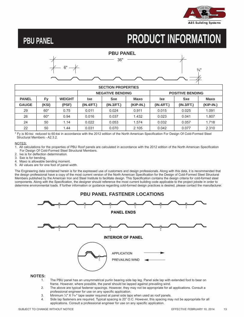
NOTES:1. The PBR panel has an unsymmetrical purlin bearing side lap leg. Panel side lap with extended foot to bear on
frame. However, where possible, the panel should be lapped against prevailing wind.2. The above are typical fastener spacings. However, they may not be appropriate for all applications. Consult a
professional engineer for use on any specifi c application.3. Minimum ½" x ³⁄ " tape sealer required at panel side laps when used as roof panels.4. Side lap fasteners are required. Typical spacing is 20" O.C. However, this spacing may not be appropriate for all
applications. Consult a professional engineer for use on any specifi c application.
36"
12" 1¹⁄₄"
PANEL ENDS
INTERIOR OF PANEL
APPLICATION
PREVAILING WIND
PBR PANEL FASTENER LOCATIONS
SECTION PROPERTIESNEGATIVE BENDING POSITIVE BENDING
PANEL Fy WEIGHT Ixe Sxe Maxo Ixe Sxe MaxoGAUGE (KSI) (PSF) (IN.4/FT.) (IN.3/FT.) (KIP-IN.) (IN.4/FT.) (IN.3/FT.) (KIP-IN.)
29 60* 0.75 0.0215 0.0325 1.2656 0.0238 0.0230 0.985926 60* 0.94 0.0309 0.0449 1.8019 0.0382 0.0381 1.675924 50 1.14 0.0420 0.0570 1.7060 0.0551 0.0567 1.696822 50 1.44 0.0567 0.0739 2.2119 0.0754 0.0787 2.3553
* Fy is 80-ksireduced to 60-ksi in accordance with the 2012 edition of the North American Specification For Design Of Cold-Formed Steel Structural Members - A2.3.2.
NOTES:1. All calculations for the properties of PBR Roof panels are calculated in accordance with the 2012 edition of the North American Specification For Design Of Cold-Formed Steel Structural Members.2. Ixe is for deflection determination.3. Sxe is for bending.4. Maxo is allowable bending moment.5. All values are for one foot of panel width.
The Engineering data contained herein is for the expressed use of customers and design professionals. Along with this data, it is recommended that the design professional have a copy of the most current version of the North American Specification for the Design of Cold-Formed Steel Structural Members published by the American Iron and Steel Institute to facilitate design. This Specification contains the design criteria for cold-formed steel components. Along with the Specification, the designer should reference the most current building code applicable to the project jobsite in order to determine environmental loads. If further information or guidance

4 SUBJECT TO CHANGE WITHOUT NOTICE EFFECTIVE FEBRUARY 10, 2014
PRODUCT INFORMATION PBR PANELPBR ROOF PANEL
ALLOWABLE UNIFORM LOADS IN POUNDS PER SQUARE FOOT 29 Gauge (0.0133”), Fy = 60 ksi, Fu = 61.5 ksiSPAN TYPE LOAD TYPE SPAN IN FEET
3.0 4.0 5.0 6.0 7.0 8.0 9.01-span NEGATIVE WIND LOAD 93.75 52.73 33.75 23.44 17.22 13.18 10.42
LIVE LOAD/DEFLECTION 67.01 32.53 16.66 9.64 6.07 4.07 2.862-span NEGATIVE WIND LOAD 61.91 37.19 24.61 17.42 12.96 10.00 7.94
LIVE LOAD/DEFLECTION 70.40 45.18 30.41 21.75 16.28 12.62 9.403-span NEGATIVE WIND LOAD 73.01 44.74 29.96 21.37 15.96 12.36 9.84
LIVE LOAD/DEFLECTION 80.00 53.43 36.52 22.73 14.32 9.59 6.744-span NEGATIVE WIND LOAD 69.51 42.31 28.22 20.08 14.97 11.58 9.21
LIVE LOAD/DEFLECTION 77.00 50.82 34.56 24.74 15.58 10.44 7.33
26 Gauge SPAN TYPE LOAD TYPE SPAN IN FEET
3.0 4.0 5.0 6.0 7.0 8.0 9.01-span NEGATIVE WIND LOAD 133.48 75.08 48.05 33.37 24.52 18.77 14.83
LIVE LOAD/DEFLECTION 119.08 52.22 26.74 15.47 9.74 6.53 4.582-span NEGATIVE WIND LOAD 114.41 66.59 43.33 30.37 22.44 17.24 13.66
LIVE LOAD/DEFLECTION 105.60 71.09 46.37 32.55 24.07 18.51 13.883-span NEGATIVE WIND LOAD 138.49 81.62 53.46 37.61 27.86 21.44 17.00
LIVE LOAD/DEFLECTION 120.00 86.91 57.11 34.86 21.95 14.71 10.334-span NEGATIVE WIND LOAD 130.70 76.70 50.12 35.22 26.06 20.05 15.89
LIVE LOAD/DEFLECTION 115.50 81.75 53.58 37.71 23.77 15.93 11.18
24 Gauge SPAN TYPE LOAD TYPE SPAN IN FEET
3.0 4.0 5.0 6.0 7.0 8.0 9.01-span NEGATIVE WIND LOAD 126.37 71.08 45.49 31.59 23.21 17.77 14.04
LIVE LOAD/DEFLECTION 125.69 70.70 38.51 22.28 14.03 9.40 6.602-span NEGATIVE WIND LOAD 120.59 69.04 44.56 31.09 22.91 17.57 13.90
LIVE LOAD/DEFLECTION 117.33 69.40 44.80 31.25 23.03 17.66 13.973-span NEGATIVE WIND LOAD 148.17 85.44 55.34 38.68 28.53 21.90 17.34
LIVE LOAD/DEFLECTION 133.33 85.87 55.62 38.89 28.68 19.34 13.584-span NEGATIVE WIND LOAD 139.13 80.03 51.77 36.16 26.66 20.46 16.19
LIVE LOAD/DEFLECTION 128.33 80.43 52.04 36.35 26.81 20.57 14.45
22 Gauge SPAN TYPE LOAD TYPE SPAN IN FEET
3.0 4.0 5.0 6.0 7.0 8.0 9.01-span NEGATIVE WIND LOAD 163.85 92.16 58.98 40.96 30.09 23.04 18.21
LIVE LOAD/DEFLECTION 174.46 98.14 52.70 30.50 19.21 12.87 9.042-span NEGATIVE WIND LOAD 168.30 96.14 61.98 43.21 31.83 24.41 19.31
LIVE LOAD/DEFLECTION 158.71 90.50 58.30 40.63 29.91 22.94 18.143-span NEGATIVE WIND LOAD 207.24 119.12 77.03 53.80 39.67 30.44 24.09
LIVE LOAD/DEFLECTION 195.75 112.25 72.50 50.61 37.24 24.95 17.524-span NEGATIVE WIND LOAD 194.44 111.53 72.04 50.29 37.06 28.43 22.50
LIVE LOAD/DEFLECTION 183.56 105.06 67.79 47.29 34.84 26.54 18.64Notes:1. Strength calculations based on the 2012 AISI standard “North American Specification for the Design of Cold-formed Steel Structural Members.”2. Allowable loads are applicable for uniform loading and spans without overhangs.3. LIVE LOAD/DEFLECTION load capacities are for those loads that push the panel against its supports. The applicable limit states are flexure,
shear, combined shear and flexure, web crippling at end and interior supports, and a deflection limit of L/180 under strength-level loads.4. NEGATIVE WIND LOAD capacities are for those loads that pull the panel away from its supports. The applicable limit states are flexure, shear,
combined shear and flexure, and a deflection limit of L/60 under 10-year wind loading.5. Panel pullover and Screw pullout capacity must be checked separately using the screws employed for each particular application when utilizing
this load chart.6. Effective yield strength has been determined in accordance with section A2.3.2 of the 2012 NAS specification.7. The use of any accessories other than those provided by the manufacturer may damage panels, void all warranties and will void all engineering data.8. This material is subject to change without notice. Please contact MBCI for most current data.
The Engineering data contained herein is for the expressed use of customers and design professionals. Along with this data, it is recommended that the design professional have a copy of the most current version of the North American Specification for the Design of Cold-Formed Steel Structural Members published by the American Iron and Steel Institute to facilitate design. This Specification contains the design criteria for cold-formed steel components. Along with the Specification, the designer should reference the most current building code applicable to the project jobsite in order to determine environmental loads. If further information or guidance regarding cold-formed design practices is desired, please contact the manufacturer.

SUBJECT TO CHANGE WITHOUT NOTICE EFFECTIVE FEBRUARY 10, 2014 5
PRODUCT INFORMATIONPBR PANELPBR WALL PANEL
ALLOWABLE UNIFORM LOADS IN POUNDS PER SQUARE FOOT 29 Gauge (0.0133”), Fy = 60 ksi, Fu = 61.5 ksiSPAN TYPE LOAD TYPE SPAN IN FEET
3.0 4.0 5.0 6.0 7.0 8.0 9.01-span NEGATIVE WIND LOAD 93.75 52.73 33.75 23.44 17.22 13.18 10.42
LIVE LOAD/DEFLECTION 67.01 41.08 26.29 18.26 13.41 10.27 8.112-span NEGATIVE WIND LOAD 61.91 37.19 24.61 17.42 12.96 10.00 7.94
LIVE LOAD/DEFLECTION 70.40 45.18 30.41 21.75 16.28 12.62 10.063-span NEGATIVE WIND LOAD 73.01 44.74 29.96 21.37 15.96 12.36 9.84
LIVE LOAD/DEFLECTION 80.00 53.43 36.52 26.39 19.89 15.50 12.404-span NEGATIVE WIND LOAD 69.51 42.31 28.22 20.08 14.97 11.58 9.21
LIVE LOAD/DEFLECTION 77.00 50.82 34.56 24.89 18.72 14.56 11.63
26 Gauge (0.0181”), Fy = 60 ksi, Fu = 61.5 ksiSPAN TYPE LOAD TYPE SPAN IN FEET
3.0 4.0 5.0 6.0 7.0 8.0 9.01-span NEGATIVE WIND LOAD 133.48 75.08 48.05 33.37 24.52 18.77 14.83
LIVE LOAD/DEFLECTION 119.08 69.83 44.69 31.04 22.80 17.46 13.792-span NEGATIVE WIND LOAD 114.41 66.59 43.33 30.37 22.44 17.24 13.66
LIVE LOAD/DEFLECTION 105.60 71.09 46.37 32.55 24.07 18.51 14.663-span NEGATIVE WIND LOAD 138.49 81.62 53.46 37.61 27.86 21.44 17.00
LIVE LOAD/DEFLECTION 120.00 86.91 57.11 40.25 29.85 22.99 18.244-span NEGATIVE WIND LOAD 130.70 76.70 50.12 35.22 26.06 20.05 15.89
LIVE LOAD/DEFLECTION 115.50 81.75 53.58 37.71 27.93 21.50 17.05
24 Gauge SPAN TYPE LOAD TYPE SPAN IN FEET
3.0 4.0 5.0 6.0 7.0 8.0 9.01-span NEGATIVE WIND LOAD 126.37 71.08 45.49 31.59 23.21 17.77 14.04
LIVE LOAD/DEFLECTION 125.69 70.70 45.25 31.42 23.09 17.68 13.972-span NEGATIVE WIND LOAD 120.59 69.04 44.56 31.09 22.91 17.57 13.90
LIVE LOAD/DEFLECTION 117.33 69.40 44.80 31.25 23.03 17.66 13.973-span NEGATIVE WIND LOAD 148.17 85.44 55.34 38.68 28.53 21.90 17.34
LIVE LOAD/DEFLECTION 133.33 85.87 55.62 38.89 28.68 22.02 17.434-span NEGATIVE WIND LOAD 139.13 80.03 51.77 36.16 26.66 20.46 16.19
LIVE LOAD/DEFLECTION 128.33 80.43 52.04 36.35 26.81 20.57 16.28
22 Gauge SPAN TYPE LOAD TYPE SPAN IN FEET
3.0 4.0 5.0 6.0 7.0 8.0 9.01-span NEGATIVE WIND LOAD 163.85 92.16 58.98 40.96 30.09 23.04 18.21
LIVE LOAD/DEFLECTION 174.46 98.14 62.81 43.62 32.04 24.53 19.382-span NEGATIVE WIND LOAD 168.30 96.14 61.98 43.21 31.83 24.41 19.31
LIVE LOAD/DEFLECTION 158.71 90.50 58.30 40.63 29.91 22.94 18.143-span NEGATIVE WIND LOAD 207.24 119.12 77.03 53.80 39.67 30.44 24.09
LIVE LOAD/DEFLECTION 195.75 112.25 72.50 50.61 37.29 28.61 22.644-span NEGATIVE WIND LOAD 194.44 111.53 72.04 50.29 37.06 28.43 22.50
LIVE LOAD/DEFLECTION 183.56 105.06 67.79 47.29 34.84 26.72 21.14Notes:1. Strength calculations based on the 2012 AISI Standard “North American Specification for the Design of Cold-formed Steel Structural Members.”2. Allowable loads are applicable for uniform loading and spans without overhangs.3. LIVE LOAD/DEFLECTION load capacities are for those loads that push the panel against its supports. The applicable limit states are flexure,
shear, combined shear and flexure, web crippling at end and interior supports, and a deflection limit of L/60 under strength-level loads.4. NEGATIVE WIND LOAD capacities are for those loads that pull the panel away from its supports. The applicable limit states are flexure, shear,
combined shear and flexure, and a deflection limit of L/60 under 10-year wind loading.5. Panel pullover and Screw pullout capacity must be checked separately using the screws employed for each particular application when utilizing
this load chart.6. Effective yield strength has been determined in accordance with section A2.3.2 of the 2012 NAS specification.7. The use of any accessories other than those provided by the manufacturer may damage panels, void all warranties and will void all engineering data.8. This material is subject to change without notice. Please contact MBCI for most current data.The Engineering data contained herein is for the expressed use of customers and design professionals. Along with this data, it is recommended that the design professional have a copy of the most current version of the North American Specification for the Design of Cold-Formed Steel Structural Members published by the American Iron and Steel Institute to facilitate design. This Specification contains the design criteria for cold-formed steel components. Along with the Specification, the designer should reference the most current building code applicable to the project jobsite in order to determine environmental loads. If further information or guidance regarding cold-formed design practices is desired, please contact the manufacturer.

6 SUBJECT TO CHANGE WITHOUT NOTICE EFFECTIVE FEBRUARY 10, 2014
PRODUCT INFORMATIONUL 90 REQUIREMENTS
PBR PANEL
Construction #3026 MSG Min. Gauge PBR Panel over Purlins at 5'- 0 ¼" O.C.
1. For Class 90 - Panel to purlin connections to be #14 Hex Head with a 5/8" O.D. washer in a 4-8-4-8 in.pattern. Panel to panel connection to be 20" O.C. with fastener located over each purlin.
2. Purlins - No. 14 MSG min. gauge steel, (55,000 psi min. yield strength.)
Construction #16126 MSG Min. Gauge PBR Panel over Purlins at 5'- 0 ¼" O.C.
1. Panel Fasteners - Panel to purlin connections to be 12-14 x 1" self-drilling Hex Head with a ⅝" O.D. washer,12" O.C. Spacing at endlap to be in a 5-7-5-7 in. patterns. Spacing for panel to panel connection to be 20"O.C. with a fastener located over each purlin.
2. Purlins - No. 14 MSG min. gauge steel, (55,000 psi min. yield strength.)
Construction #7926 MSG Min. Gauge PBR Panel over Purlins at 5'- 0 ¼" O.C.
1. Panel Fasteners - Panel to purlin connections to be #14 Hex Head with a ⅝" O.D. washer, 6" O.C. in5-7-5-7 in. pattern. Endlap spacing to be 6 in. O.C. Spacing for panel to panel connection to be 20" O.C.
2. Purlins - No. 16 MSG min. gauge steel. (55,000 psi min. yield strength); or min. H series open web steel joists.
Construction #54226 MSG Min. Gauge PBR Panel over Purlins at 5'- 0 ³⁄ " O.C.
1. Panel Fasteners - Panel to purlin connections to be 12-14x1" self-drilling Hex Head with a ⅝" O.D.washer,12" O.C. Spacing at endlap to be in a 5-7-5-7 in. pattern. Spacing for panel to panel connection to be20" O.C. with a fastener located over each purlin.
2. Building Units - Translucent Panels.3. Translucent Panel Rib and Purlin Reinforcement - See UL 90 light transmitting panel installation instructions.4. Purlins - No. 16 MSG min. gauge steel. (55,000 psi min. yield strength).
IMPACT RESISTANCEPBU panels carry a Class 4 rating under UL-2218 "Test Standard For Impact Resistance"
FIRE RESISTANCE RATING1. Deck: NC Class A
Incline: UnlimitedThe panel qualifies for a Class A Fire Rating in compliance with Underwriters Laboratories StandardUL-263 when installed over a non-combustible substrate. A Class C Fire Rating will be qualified forover a combustible substrate.
Look for classification marking on product.
CAUTIONThe above listings are summaries of Construction Numbers. For UL 90 rated roof requirements and complete design information, see the
Underwriters Laboratories Building Materials Directory. If you have any questions, call MBCI before proceeding.
PBR PANEL

PRODUCT CHECKLIST
SUBJECT TO CHANGE WITHOUT NOTICE EFFECTIVE FEBRUARY 10, 2014 7
PRODUCT INFORMATIONPBR PANEL
36" 12" 1¹⁄₄"
8"
4"
4"
COLOR
1³⁄₄" 2"
COLOR
11¹⁄₂" 11¹⁄₂"
SPECIFY ANGLE
S PECIFY ANGLE
45°
18³⁄₄" 18³⁄₄"
2"
11" 11"
45°
SPECIFY ANGLE 2"
Standard
Extended
5" 1³⁄₄"
4"
4"
2"
1¹⁄₄"
1³⁄₄"
COLOR
6"
5¹⁄₂"
COLOR 6"
1³⁄₄"
COLOR
5"
³⁄₄"
5"
3¹⁄₂"
⁵⁄₈"
COLOR
4"
4"
4"
1" ³⁄₄"
DIM. A
90° - ° OF ROOF PITCH
90° + ° OF ROOF SLOPE
COLOR
4"
4"
4"
1" 3¹⁄₂"
DIM. A
90° + ° of ROOF SLOPE
90° + ° of ROOF SLOPE
COLOR
PBR Panel
Flat Ridge/Hip Flashing
Parapet High Eave
Sculptered Hang-On Gutter
Ridge Cap
Valley Flashing
Parapet Rake
Sculptered Eave Gutter
Sculptered High Side Eave
Sculptered Rake
Eave Trim
Gutter Strap
Gutter End
Specify Left or RightSpecify Gutter part no.Specify Roof SlopeSpecify Roof Slope
Specify Roof Slope
Maximum Roof Pitch 5:12Specify Pitch Specify Roof Slope
Specify Roof Slope
FL-18A FL-18
FL-952
FL-18C
FL-874
FL-38A
PBR Panel FL-49 2'-6" FL-51 3'-0"
FL-558
FL-556
FL-893
FL-19
FL-16
FL-17

PRODUCT CHECKLIST
8 SUBJECT TO CHANGE WITHOUT NOTICE EFFECTIVE FEBRUARY 10, 2014
PRODUCT INFORMATIONInside Corner Trim
Base Trim (With Sheeting Notch)
Downspouts
Base Trim (Without Sheeting Notch)
LTP
Sealant
Corner Trim - Outside
Jamb Trim
Head Trim
Closures
NOTE: 25' Per tube at ¼" bead *Special order - requires two-week lead time
HW-456
HW-455 ½" X ³⁄ " HW-507
1" X ³⁄ " HW-506
Triple BeadHW-502
Color Part No. White HW-540 Gray HW-540
Almond HW-540 Bronze HW-540
High Strength Fiberglass High Strength Fiberglass
U.V. Resistant
FL-72
FL-800 FL-31A - With Kick-Out
FL-31 - Straight
FL-530
FL-26
FL-23
FL-830
1³⁄₄"
COLOR
1³⁄₄"
³⁄₄"4¹⁄₂"
³⁄₄"
4¹⁄₂"
4"
4"3¹⁄₂"
3¹⁄₂"
3⁵⁄₁₆"
3⁵⁄₁₆"
COLOR
1³⁄₄"
1³⁄₄"
³⁄₄"
³⁄₄"
1³⁄₄"
⁵⁄₈"
135�
COLOR
3¹⁄₄" 2"
45�
COLOR
2¹⁄₂
"1³⁄₄"
¹⁄₂" 1¹⁄₄"
2"
¹⁄₂"
COLOR
1¹⁄₄"
12-14 X 1¼" Driller
12-14 x 1" Pancake Head Driller
12-14 X 1¼" Long Life Driller
⅛ X 3⁄16" Stainless Steel Pop Rivet
¼"-14 X ⅞" Long Life Lap Tek
¼"-14 X 1¼" Long Life Driller with 1⅛" O.D. washer
¼"-14 X ⅞" Long Life LapTek with 1⅛" O.D. Washer
Fasteners
#43L
#17A
#12A
#3
#4
#44L
#14
1¹⁄₄"
1³⁄₈"COLOR
2¹⁄₂"
Inside
Outside
Beveled Inside*
Beveled Outside*
TRIPLE BEAD
URETHANESEALANT 11 OZ.
PBR PANEL
Note: It is the users responsibility to ensure that the installation and use of all light transmitting panels comply with State, Federal and OSHA regulations and laws, including, but not limited to, guarding all light transmitting panels with screens, fixed standard railings, or other acceptable safety controls that prevent fall-through.

SUBJECT TO CHANGE WITHOUT NOTICE EFFECTIVE FEBRUARY 10, 2014 9
PRODUCT INFORMATION
Endlap1. Stack 2 continuous layers of ½" X ³⁄ " tape sealer on top of each other and must be installed between weather
infiltration point and fastener.2. Install Fastener #3 (12-14 X 1¼" Long Life driller) on each side of major ribs of panel (two fasteners per foot).3. Fastener #17A (12-14 X 1¼" self-driller) are available as an alternate when long life fasteners are not desired.
NOTES:Sidelap
1. ½" X ³⁄ " tape sealer must be installed between weather infi ltration point and fastener.2. Install Fastener #4 (¼"-14 X ⅞" Long Life Lap Tek) at 20" O.C. at roof panel side laps and 24" O.C. at wall panel
side laps.3. When possible, install panels such that sidelaps are nested away from prevailing winds.4. Fastener #4A (¼"-14 X ⅞" Lap Tek) are available as an alternate when long life fasteners are not desired.
SLOPE
ENDLAP ATTACHMENT (SEE DETAIL B)
PBR PANEL
¹⁄₂" x ³⁄₃₂"TAPE SEALER(TWO LAYERS)
4"
FASTENER #3 6 EACH PER PANEL
FASTENER #4 20" O.C. @ ROOF 24” O.C. @ WALL
¹⁄₂" X ³⁄₃₂" TAPE SEALER
PBR PANEL
FASTENER #3 HIGH SIDE ATTACHMENT (6 FASTENERS PER PANEL)
FASTENER #3 EAVE ATTACHMENT (6 FASTENERS PER PANEL)
FASTENER #3 INTERMEDIATE PURLIN ATTACHMENT (3 FASTENERS PER PANEL)
A A
DETAIL "A" DETAIL "B"
PBR PANEL
10 SUBJECT TO CHANGE WITHOUT NOTICE EFFECTIVE FEBRUARY 10, 2014
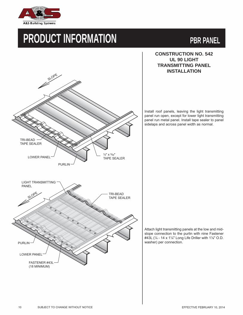
PRODUCT INFORMATION PBR PANELCONSTRUCTION NO. 542
UL 90 LIGHTTRANSMITTING PANEL
INSTALLATIONSLOPE
TRI-BEAD TAPE SEALER
¹⁄₂" x ³⁄₃₂" TAPE SEALER LOWER PANEL
PURLIN
SLOPE
FASTENER #43L (18 MINIMUM)
LIGHT TRANSMITTING PANEL
PURLIN
LOWER PANEL
TRI-BEAD TAPE SEALER
Install roof panels, leaving the light transmitting panel run open, except for lower light transmitting panel run metal panel. Install tape sealer to panel sidelaps and across panel width as normal.
Attach light transmitting panels at the low and mid-slope connection to the purlin with nine Fastener #43L (¼ - 14 x 1¼" Long Life Driller with 1⅛" O.D. washer) per connection.
SUBJECT TO CHANGE WITHOUT NOTICE EFFECTIVE FEBRUARY 10, 2014 11
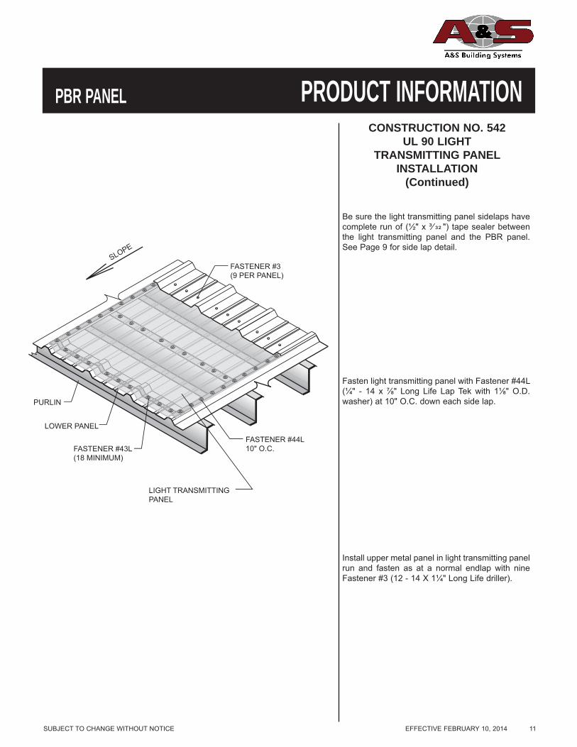
PRODUCT INFORMATIONPBR PANELCONSTRUCTION NO. 542
UL 90 LIGHTTRANSMITTING PANEL
INSTALLATION(Continued)
FASTENER #44L 10" O.C.
SLOPE
FASTENER #43L (18 MINIMUM)
LIGHT TRANSMITTING PANEL
PURLIN
LOWER PANEL
FASTENER #3 (9 PER PANEL)
Be sure the light transmitting panel sidelaps have complete run of (½" x ³⁄ ") tape sealer between the light transmitting panel and the PBR panel. See Page 9 for side lap detail.
Fasten light transmitting panel with Fastener #44L (¼" - 14 x ⅞" Long Life Lap Tek with 1⅛" O.D. washer) at 10" O.C. down each side lap.
Install upper metal panel in light transmitting panel run and fasten as at a normal endlap with nine Fastener #3 (12 - 14 X 1¼" Long Life driller).

12 SUBJECT TO CHANGE WITHOUT NOTICE EFFECTIVE FEBRUARY 10, 2014
PRODUCT INFORMATION36"
6" ³⁄₄"
GENERAL DESCRIPTION
Signature is a registered trademark of Metal Building Components, L.P. Galvalume and Galvalume Plus are registered and protected trademarks of BIEC International, Inc.
PBU PANELCoverage Width - 36"Minimum Slope - 1:12Panel Attachment - See page 17Panel Substrate - Galvalume®
Gauge - 26 standard - 29, 24 and 22 also availableCoatings- Galvalume Plus®, Signature® 200* and Signature® 300*
1. PBU panel is a structural roof and wall panel. This panel can be installed directly over purlins or joists.PBU panel is UL 90 rated per construction number 39.
2. PBU panel is recommended for 1:12 or greater roof slopes.3. Field applied tape sealant is required at panel sidelaps and endlaps.4. PBU panel is a through-fastened panel. For proper fastener application, see page 12 and page 17.5. The information in this manual is believed to be correct and accurate. It should not be used for any specific
application without being reviewed by a registered professional engineer.
ARCHITECT/ENGINEER INFORMATION
PRODUCT SELECTION CHARTGAUGE GALVALUME PLUS® SIGNATURE® 200* SIGNATURE® 300*
22 gauge ● ■ ■24 gauge ● ■ ■26 gauge ● ● ●29 gauge ● ● ■
● - Available in any quantity.■ - Minimum quantity may be required.*See Commercial/Industrial color chart for available colors.
PBU PANEL
SUBJECT TO CHANGE WITHOUT NOTICE EFFECTIVE FEBRUARY 10, 2014 13
PRODUCT INFORMATIONPBU PANELPBU PANEL
NOTES:1. The PBU panel has an unsymmetrical purlin bearing side lap leg. Panel side lap with extended foot to bear on
frame. However, where possible, the panel should be lapped against prevailing wind.2. The above are typical fastener spacings. However, they may not be appropriate for all applications. Consult a
professional engineer for use on any specifi c application.3. Minimum ½" X ³⁄ " tape sealer required at panel side laps when used as roof panels.4. Side lap fasteners are required. Typical spacing is 20” O.C. However, this spacing may not be appropriate for all
applications. Consult a professional engineer for use on any specifi c application.
36"
6" ³⁄₄"
PANEL ENDS
INTERIOR OF PANEL
APPLICATION
PREVAILING WIND
PBU PANEL FASTENER LOCATIONS
SECTION PROPERTIESNEGATIVE BENDING POSITIVE BENDING
PANEL Fy WEIGHT Ixe Sxe Maxo Ixe Sxe MaxoGAUGE (KSI) (PSF) (IN.4/FT.) (IN.3/FT.) (KIP-IN.) (IN.4/FT.) (IN.3/FT.) (KIP-IN.)
29 60* 0.75 0.011 0.024 0.911 0.015 0.025 1.09126 60* 0.94 0.016 0.037 1.432 0.023 0.041 1.80724 50 1.14 0.022 0.053 1.574 0.032 0.057 1.71822 50 1.44 0.031 0.070 2.105 0.042 0.077 2.310
* Fy is 80-ksi reduced to 60-ksi in accordance with the 2012 edition of the North American Specification For Design Of Cold-Formed SteelStructural Members - A2.3.2.
NOTES:1. All calculations for the properties of PBU Roof panels are calculated in accordance with the 2012 edition of the North American Specification For Design Of Cold-Formed Steel Structural Members.2. Ixe is for deflection determination.3. Sxe is for bending.4. Maxo is allowable bending moment.5. All values are for one foot of panel width.
The Engineering data contained herein is for the expressed use of customers and design professionals. Along with this data, it is recommended that the design professional have a copy of the most current version of the North American Specification for the Design of Cold-Formed Steel Structural Members published by the American Iron and Steel Institute to facilitate design. This Specification contains the design criteria for cold-formed steel components. Along with the Specification, the designer should reference the most current building code applicable to the project jobsite in order to determine environmental loads. If further information or guidance regarding cold-formed design practices is desired, please contact the manufacturer.

14 SUBJECT TO CHANGE WITHOUT NOTICE EFFECTIVE FEBRUARY 10, 2014
PRODUCT INFORMATIONPBU ROOF PANEL
ALLOWABLE UNIFORM LOADS IN POUNDS PER SQUARE FOOT
PBU PANEL
29 Gauge (0.0133”), Fy = 60 ksi, Fu = 61.5 ksiSPAN TYPE LOAD TYPE SPAN IN FEET
3.0 4.0 5.0 6.0 7.0 8.0 9.01-span NEGATIVE WIND LOAD 67.49 37.96 24.30 16.87 11.91 7.98 5.60
LIVE LOAD/DEFLECTION 48.81 20.59 10.54 6.10 3.84 2.57 1.812-span NEGATIVE WIND LOAD 78.35 44.67 28.77 20.05 14.76 11.32 8.95
LIVE LOAD/DEFLECTION 66.02 37.49 24.10 16.78 11.80 7.91 5.553-span NEGATIVE WIND LOAD 96.65 55.41 35.78 24.97 18.40 14.12 11.17
LIVE LOAD/DEFLECTION 81.75 46.61 24.37 14.10 8.88 5.95 4.184-span NEGATIVE WIND LOAD 90.63 51.85 33.46 23.34 17.19 13.19 10.43
LIVE LOAD/DEFLECTION 76.56 43.59 26.23 15.18 9.56 6.40 4.50
26 Gauge (0.0181”), Fy = 60 ksi, Fu = 61.5 ksiSPAN TYPE LOAD TYPE SPAN IN FEET
3.0 4.0 5.0 6.0 7.0 8.0 9.01-span NEGATIVE WIND LOAD 106.10 59.68 38.20 26.52 17.48 11.71 8.22
LIVE LOAD/DEFLECTION 75.46 31.84 16.30 9.43 5.94 3.98 2.792-span NEGATIVE WIND LOAD 130.50 74.21 47.74 33.24 24.46 18.75 14.83
LIVE LOAD/DEFLECTION 104.42 59.14 37.97 26.19 16.49 11.05 7.763-span NEGATIVE WIND LOAD 161.40 92.19 59.43 41.44 30.45 23.31 17.07
LIVE LOAD/DEFLECTION 129.63 68.21 34.92 20.21 12.73 8.53 5.994-span NEGATIVE WIND LOAD 151.20 86.23 55.55 38.71 28.50 21.85 17.28
LIVE LOAD/DEFLECTION 121.28 68.83 37.30 21.58 13.59 9.11 6.40
24 Gauge (0.0223”), Fy = 50 ksi, Fu = 60 ksiSPAN TYPE LOAD TYPE SPAN IN FEET
3.0 4.0 5.0 6.0 7.0 8.0 9.01-span NEGATIVE WIND LOAD 116.62 65.60 41.98 29.15 21.42 15.90 11.17
LIVE LOAD/DEFLECTION 102.37 43.19 22.11 12.80 8.06 5.40 3.792-span NEGATIVE WIND LOAD 124.52 70.69 45.44 31.63 23.27 17.84 14.10
LIVE LOAD/DEFLECTION 114.52 64.93 41.71 29.02 20.38 13.65 9.593-span NEGATIVE WIND LOAD 154.22 87.90 56.61 39.45 29.04 22.26 17.61
LIVE LOAD/DEFLECTION 142.04 80.80 43.73 25.31 15.94 10.68 7.504-span NEGATIVE WIND LOAD 144.41 82.20 52.90 36.85 27.12 20.79 16.44
LIVE LOAD/DEFLECTION 132.94 75.53 46.46 26.89 16.93 11.34 7.97
22 Gauge (0.0286”), Fy = 50 ksi, Fu = 60 ksiSPAN TYPE LOAD TYPE SPAN IN FEET
3.0 4.0 5.0 6.0 7.0 8.0 9.01-span NEGATIVE WIND LOAD 155.91 87.70 56.13 38.98 28.64 21.93 15.67
LIVE LOAD/DEFLECTION 136.57 57.62 29.50 17.07 10.75 7.20 5.062-span NEGATIVE WIND LOAD 167.07 94.95 61.06 42.51 31.28 23.98 18.96
LIVE LOAD/DEFLECTION 152.86 86.72 55.73 38.78 26.14 17.51 12.303-span NEGATIVE WIND LOAD 206.75 117.99 76.04 53.00 39.03 29.93 23.67
LIVE LOAD/DEFLECTION 189.46 107.88 56.18 32.51 20.47 13.72 9.634-span NEGATIVE WIND LOAD 193.65 110.35 71.06 49.52 36.45 27.95 22.10
LIVE LOAD/DEFLECTION 177.36 100.86 59.64 34.52 21.74 14.56 10.23Notes:1. Strength calculations based on the 2012 AISI Standard “North American Specification for the Design of Cold-formed Steel Structural Members.”2. Allowable loads are applicable for uniform loading and spans without overhangs.3. LIVE LOAD/DEFLECTION load capacities are for those loads that push the panel against its supports. The applicable limit states are flexure,
shear, combined shear and flexure, web crippling at end and interior supports, and a deflection limit of L/180 under strength-level loads.4. NEGATIVE WIND LOAD capacities are for those loads that pull the panel away from its supports. The applicable limit states are flexure, shear,
combined shear and flexure, and a deflection limit of L/60 under 10-year wind loading.5. Panel pullover and Screw pullout capacity must be checked separately using the screws employed for each particular application when utilizing
this load chart.6. Effective yield strength has been determined in accordance with section A2.3.2 of the 2012 NAS specification.7. The use of any accessories other than those provided by the manufacturer may damage panels, void all warranties and will void all engineering
data.8. This material is subject to change without notice. Please contact MBCI for most current data.
The Engineering data contained herein is for the expressed use of customers and design professionals. Along with this data, it is recommended that the design professional have a copy of the most current version of the North American Specification for the Design of Cold-Formed Steel Structural Members published by the American Iron and Steel Institute to facilitate design. This Specification contains the design criteria for cold-formed steel components. Along with the Specification, the designer should reference the most current building code applicable to the project jobsite in order to determine environmental loads. If further information or guidance regarding cold-formed design practices is desired, please contact the manufacturer.

SUBJECT TO CHANGE WITHOUT NOTICE EFFECTIVE FEBRUARY 10, 2014 15
PRODUCT INFORMATIONPBU WALL PANEL
ALLOWABLE UNIFORM LOADS IN POUNDS PER SQUARE FOOT 29 Gauge SPAN TYPE LOAD TYPE SPAN IN FEET
3.0 4.0 5.0 6.0 7.0 8.0 9.01-span NEGATIVE WIND LOAD 67.49 37.96 24.30 16.87 11.91 7.98 5.60
LIVE LOAD/DEFLECTION 80.84 45.47 29.10 20.21 14.85 11.03 7.752-span NEGATIVE WIND LOAD 78.35 44.67 28.77 20.05 14.76 11.32 8.95
LIVE LOAD/DEFLECTION 66.02 37.49 24.10 16.78 12.34 9.46 7.483-span NEGATIVE WIND LOAD 96.65 55.41 35.78 24.97 18.40 14.12 11.17
LIVE LOAD/DEFLECTION 81.75 46.61 30.02 20.92 15.40 11.81 9.344-span NEGATIVE WIND LOAD 90.63 51.85 33.46 23.34 17.19 13.19 10.43
LIVE LOAD/DEFLECTION 76.56 43.59 28.05 19.54 14.39 11.03 8.72
26 Gauge SPAN TYPE LOAD TYPE SPAN IN FEET
3.0 4.0 5.0 6.0 7.0 8.0 9.01-span NEGATIVE WIND LOAD 106.10 59.68 38.20 26.52 17.48 11.71 8.22
LIVE LOAD/DEFLECTION 133.83 75.28 48.18 33.46 24.58 17.05 11.982-span NEGATIVE WIND LOAD 130.50 74.21 47.74 33.24 24.46 18.75 14.83
LIVE LOAD/DEFLECTION 104.42 59.14 37.97 26.42 19.43 14.89 11.773-span NEGATIVE WIND LOAD 161.40 92.19 59.43 41.44 30.45 23.31 17.07
LIVE LOAD/DEFLECTION 129.63 73.64 47.35 32.96 24.26 18.59 14.704-span NEGATIVE WIND LOAD 151.20 86.23 55.55 38.71 28.50 21.85 17.28
LIVE LOAD/DEFLECTION 121.28 68.83 44.23 30.79 22.65 17.36 13.72
24 Gauge SPAN TYPE LOAD TYPE SPAN IN FEET
3.0 4.0 5.0 6.0 7.0 8.0 9.01-span NEGATIVE WIND LOAD 116.62 65.60 41.98 29.15 21.42 15.90 11.17
LIVE LOAD/DEFLECTION 127.22 71.56 45.80 31.81 23.37 17.89 14.142-span NEGATIVE WIND LOAD 124.52 70.69 45.44 31.63 23.27 17.84 14.10
LIVE LOAD/DEFLECTION 114.52 64.93 41.71 29.02 21.35 16.36 12.933-span NEGATIVE WIND LOAD 154.22 87.90 56.61 39.45 29.04 22.26 17.61
LIVE LOAD/DEFLECTION 142.04 80.80 51.98 36.20 26.64 20.42 16.154-span NEGATIVE WIND LOAD 144.41 82.20 52.90 36.85 27.12 20.79 16.44
LIVE LOAD/DEFLECTION 132.94 75.53 48.57 33.81 24.88 19.07 15.08
22 Gauge SPAN TYPE LOAD TYPE SPAN IN FEET
3.0 4.0 5.0 6.0 7.0 8.0 9.01-span NEGATIVE WIND LOAD 155.91 87.70 56.13 38.98 28.64 21.93 15.67
LIVE LOAD/DEFLECTION 171.09 96.24 61.59 42.77 31.42 24.06 19.012-span NEGATIVE WIND LOAD 167.07 94.95 61.06 42.51 31.28 23.98 18.96
LIVE LOAD/DEFLECTION 152.86 86.72 55.73 38.78 28.53 21.86 17.293-span NEGATIVE WIND LOAD 206.75 117.99 76.04 53.00 39.03 29.93 23.67
LIVE LOAD/DEFLECTION 189.46 107.88 69.44 48.37 35.61 27.30 21.594-span NEGATIVE WIND LOAD 193.65 110.35 71.06 49.52 36.45 27.95 22.10
LIVE LOAD/DEFLECTION 177.36 100.86 64.88 45.18 33.25 25.49 20.15
Notes:1. Strength calculations based on the 2012 AISI Standard “North American Specification for the Design of Cold-formed Steel Structural Members.”2. Allowable loads are applicable for uniform loading and spans without overhangs.3. LIVE LOAD/DEFLECTION load capacities are for those loads that push the panel against its supports. The applicable limit states are flexure,
shear, combined shear and flexure, web crippling at end and interior supports, and a deflection limit of L/60 under strength-level loads.4. NEGATIVE WIND LOAD capacities are for those loads that pull the panel away from its supports. The applicable limit states are flexure, shear,
combined shear and flexure, and a deflection limit of L/60 under 10-year wind loading.5. Panel pullover and Screw pullout capacity must be checked separately using the screws employed for each particular application when utilizing
this load chart.6. Effective yield strength has been determined in accordance with section A2.3.2 of the 2012 NAS specification.7. The use of any accessories other than those provided by the manufacturer may damage panels, void all warranties and will void all engineering data.8. This material is subject to change without notice. Please contact MBCI for most current data.
The Engineering data contained herein is for the expressed use of customers and design professionals. Along with this data, it is recommended that the design professional have a copy of the most current version of the North American Specification for the Design of Cold-Formed Steel Structural Members published by the American Iron and Steel Institute to facilitate design. This Specification contains the design criteria for cold-formed steel components. Along with the Specification, the designer should reference the most current building code applicable to the project jobsite in order to determine environmental loads. If further information or guidance regarding cold-formed design practices is desired, please contact the manufacturer.
PBU PANEL

16 SUBJECT TO CHANGE WITHOUT NOTICE EFFECTIVE FEBRUARY 10, 2014
PRODUCT INFORMATIONUL 90 REQUIREMENTS
PBU PANEL
Construction #39
26 MSG Min. Gauge PBU Panel over Purlins at 5'- 0 ¼" O.C.
1. Panel Fasteners - Panel to purlin connections to be #14 self-drilling, Hex Head with a ⅝" O.D. washer,
6" O.C. Spacing at endlaps to be 6" O.C. Spacing for panel to panel connections to be 12" O.C.
2. Purlins - No. 16 MSG min gauge steel. (55,000 psi min. yield strength)
IMPACT RESISTANCE
PBU panels carry a Class 4 rating under UL-2218 "Test Standard For Impact Resistance"
FIRE RESISTANCE RATING
1. Deck: NC Class A
Incline: Unlimited
The panel qualifies for a Class A Fire Rating in compliance with Underwriters Laboratories Standard
UL-263 when installed over a non-combustible substrate. A Class C Fire Rating will be qualified for
over a combustible substrate.
Look for classification marking on product.
CAUTIONThe above listings are summaries of Construction Numbers. For UL 90 rated roof requirements and complete design information, see the
Underwriters Laboratories Building Materials Directory. If you have any questions, call MBCI before proceeding.
PBU PANEL

PRODUCT CHECKLIST
SUBJECT TO CHANGE WITHOUT NOTICE EFFECTIVE FEBRUARY 10, 2014 17
PRODUCT INFORMATIONPBU PANEL
36" 6" ³⁄₄"
5" 1¹⁄₈"
4"
4"
2"
1⁷⁄₈"
1³⁄₄"
COLOR
4"
4"
4"
1" ³⁄₄"
DIM "A"
90°-° of Roof Pitch
90°+° of Roof Pitch
COLOR
8"
4"
4"
COLOR
1³⁄₄" 2"
6"
5¹⁄₂"
COLOR 4 ¹⁄₂"
COLOR
³⁄₄"
7 ¹⁄₈"
1¹⁄₈"
PBU Panel
Flat Ridge/Hip Flashing
Parapet High Eave
Sculptered Hang-On Gutter
Ridge Cap
Valley Flashing
Parapet Rake
Sculptered Eave Gutter
Sculptered High Side Eave
Sculptered Rake
Eave Trim
Gutter Strap
Gutter End
Specify Left or RightSpecify Gutter part no.Specify Roof SlopeSpecify Roof Slope
Specify Roof Slope
Maximum Roof Pitch 5:12Specify Pitch Specify Roof Slope
Specify Roof Slope
FL-18A FL-512
FL-954
FL-512B
FL-874
FL-38
PBU Panel FL-50 2'-6" FL-52 3'-0"
FL-558
FL-556
FL-893
FL-19
FL-15
FL-17
5"
3¹⁄₂"
⁵⁄₈"
COLOR
COLOR
11¹⁄₂" 11¹⁄₂"
SPECIFY ANGLES PECIFY ANGLE
45°
18³⁄₄" 18³⁄₄"
2"
11" 11"
45°
SPECIFY ANGLE 2"
Standard
Extended
4"
4"
4"
DIM "A"
1"
3¹⁄₂"
90°+° of Roof Pitch
90°+° of Roof Pitch COLOR

PRODUCT CHECKLIST
18 SUBJECT TO CHANGE WITHOUT NOTICE EFFECTIVE FEBRUARY 10, 2014
PRODUCT INFORMATIONInside Corner Trim
Base Trim (With Sheeting Notch)
Downspouts
Base Trim (Without Sheeting Notch)
LTP
Sealant
Corner Trim - Outside
Jamb Trim
Head Trim
Closures
NOTE: 25' Per tube at ¼" bead *Special order - requires two-week lead time
HW-460
HW-459 ½" X ³⁄ " HW-507
1" X ³⁄ " HW-506
Triple BeadHW-502
High Strength Fiberglass High Strength Fiberglass
U.V. Resistant
FL-72
FL-810 FL-31A - With Kick-Out
FL-31 - Straight
FL-530
FL-514A
FL-21
FL-840
1¹⁄₁₆"
COLOR
1¹⁄₁₆"
³⁄₄"3"
³⁄₄"
3"
4"
4"3¹⁄₂"
3¹⁄₂"
1¹⁄₄"
2"
¹⁄₂"
COLOR
1¹⁄₄"
Be�eled Outside*
Inside
Outside
Be�eled Inside*
TRIPLE BEAD
URETHANE
1"
1"
2¹⁄₂"
COLOR
2"
45�
COLOR
2¹⁄₂
"1³⁄₄"
¹⁄₂"
1³⁄₄"
⁵⁄₈"
135�
COLOR
3¹⁄₄"
3 ⁵⁄₁₆"
³⁄₄"3 ⁵⁄₁₆"
COLOR
1¹⁄₈"
1¹⁄₈"
³⁄₄"
PBU PANEL
Note: It is the users responsibility to ensure that the installation and use of all light transmitting panels comply with State, Federal and OSHA regulations and laws, including, but not limited to, guarding all light transmitting panels with screens, fixed standard railings, or other acceptable safety controls that prevent fall-through.
Color Part No. White HW-540 Gray HW-540
Almond HW-540 Bronze HW-540
12-14 X 1¼" Driller
12-14 x 1" Pancake Head Driller
12-14 X 1¼" Long Life Driller
⅛ X 3⁄16" Stainless Steel Pop Rivet
¼"-14 X ⅞" Long Life Lap Tek
¼"-14 X 1¼" Long Life Driller with 1⅛" O.D. washer
¼"-14 X ⅞" Long Life LapTek with 1⅛" O.D. Washer
Fasteners
#43L
#17A
#12A
#3
#4
#44L
#14

SUBJECT TO CHANGE WITHOUT NOTICE EFFECTIVE FEBRUARY 10, 2014 19
PRODUCT INFORMATIONPBU PANELATTACHMENTPBU PANEL
Endlap1. Stack 2 continuous layers of ½" X ³⁄ " tape sealer on top of each other and must be installed between weather
infiltration point and fastener.2. Install Fastener #3 (12-14 X 1¼" Long Life driller) on each side of major ribs of panel (two fasteners per foot).3. Fastener #17A (12-14 X 1¼" self-driller) are available as an alternate when long life fasteners are not desired.
NOTES:Sidelap
1. ½" X ³⁄ " tape sealer must be installed between weather infi ltration point and fastener.2. Install Fastener #4 (¼"-14 X ⅞" Long Life Lap Tek) at 20" on center.3. When possible, install panels such that sidelaps are nested away from prevailing winds.4. Fastener #4A (¼"-14 X ⅞" Lap Tek) are available as an alternate when long life fasteners are not desired.
SLOPE
ENDLAP ATTACHMENT (SEE DETAIL B)
PBU PANEL
FASTENER #3 HIGH SIDE ATTACHMENT (6 FASTENERS PER PANEL)
FASTENER #3 EAVE ATTACHMENT (6 FASTENERS PER PANEL)
FASTENER #3 INTERMEDIATE PURLIN ATTACHMENT (3 FASTENERS PER PANEL)
A A
FASTENER #4 20" O.C.
¹⁄₂" X ³⁄₃₂" TAPE SEALER
¹⁄₂" x ³⁄₃₂"TAPE SEALER(TWO LAYERS)
4"
FASTENER #3 6 EACH PER PANEL
PBU PANEL
DETAIL "A"
DETAIL "B"

20 SUBJECT TO CHANGE WITHOUT NOTICE EFFECTIVE FEBRUARY 10, 2014
PRODUCT INFORMATIONLIGHT TRANSMITTINGPANEL INSTALLATION
Attach light transmitting panels at the low and mid-slope connection to the purlin with six Fastener #43L (¼ - 14 x 1¼" Long Life Driller with 1⅛" O.D. washer) per connection.
Install roof panels, leaving the light transmitting panel run open, except for lower light transmitting panel run metal panel. Install tape sealer to panel sidelaps and across panel width as normal.
SLOPE
FASTENER #43L (12 MINIMUM)
LIGHT TRANSMITTING PANEL
PURLIN
LOWER PANEL
TRI-BEAD TAPE SEALER
SLOPE
TRI-BEAD TAPE SEALER
¹⁄₂" x ³⁄₃₂" TAPE SEALER LOWER PANEL
PURLIN
PBU PANEL

SUBJECT TO CHANGE WITHOUT NOTICE EFFECTIVE FEBRUARY 10, 2014 21
PRODUCT INFORMATIONPBU PANELLIGHT TRANSMITTINGPANEL INSTALLATION
(Continued)
Be sure the light transmitting panel sidelaps have complete run of (½" x ³⁄ ") tape sealer between the light transmitting panel and the PBU panel. See Page 19 for side lap detail.
Fasten light transmitting panel with Fastener#44L (¼" - 14 x ⅞" Long Life Lap Tek with 1⅛"O.D. washer) at 10" O.C. down each side lap.
Install upper metal panel in light transmittingpanel run and fasten as at a normal endlap withsix Fastener #3 (12 - 14 X 1¼" Long Life driller).
FASTENER #44L10" O.C.
SLOPE
FASTENER #43L(12 MINIMUM)
LIGHT TRANSMITTING PANEL
PURLIN
LOWER PANEL
FASTENER #3(6 PER PANEL)
22 SUBJECT TO CHANGE WITHOUT NOTICE EFFECTIVE FEBRUARY 10, 2014
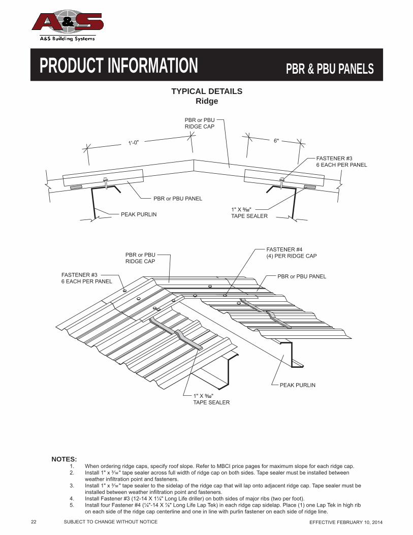
PRODUCT INFORMATIONTYPICAL DETAILS
Ridge
NOTES:1. When ordering ridge caps, specify roof slope. Refer to MBCI price pages for maximum slope for each ridge cap.2. Install 1" x ³⁄ " tape sealer across full width of ridge cap on both sides. Tape sealer must be installed between
weather infi ltration point and fasteners.3. Install 1" x ³⁄ " tape sealer to the sidelap of the ridge cap that will lap onto adjacent ridge cap. Tape sealer must be
installed between weather infi ltration point and fasteners.4. Install Fastener #3 (12-14 X 1¼" Long Life driller) on both sides of major ribs (two per foot).5. Install four Fastener #4 (¼"-14 X ⅞" Long Life Lap Tek) in each ridge cap sidelap. Place (1) one Lap Tek in high rib
on each side of the ridge cap centerline and one in line with purlin fastener on each side of ridge line.
1'-0"
PEAK PURLIN
FASTENER #3 6 EACH PER PANEL
FASTENER #3 6 EACH PER PANEL
PBR or PBU PANEL
PBR or PBU RIDGE CAP
PBR or PBU PANEL
PBR or PBU RIDGE CAP
FASTENER #4(4) PER RIDGE CAP
PEAK PURLIN
6"
1" X ³⁄₃₂"TAPE SEALER
1" X ³⁄₃₂"TAPE SEALER
PBR & PBU PANELS

SUBJECT TO CHANGE WITHOUT NOTICE EFFECTIVE FEBRUARY 10, 2014 23
PRODUCT INFORMATIONTYPICAL DETAILS
High Side Eave
NOTES:1. Install outside closure, with 1" x ³⁄ " tape sealer top and bottom, across width of PBR or PBU panels.2. Install Sculptured High Side Eave to PBR or PBU panels at each major rib with Fastener #4 (¼"-14 X ⅞" Long Life
Lap Tek). Sculptured high side eave trim should overhang outside closures ½" - 1".3. Attach front face of sculptured high side eave trim to wall with fasteners or cleat as required for wall substrate.4. Trim laps should be approximately 3" with suffi cient amount of Fastener #4 (¼"-14 X ⅞" Long Life Lap Tek) to hold
lap together. Apply bead of urethane sealant between trim at 3" lap.
OUTSIDE CLOSURE
PBR or PBU PANEL
PBR or PBU PANEL
FASTENER #3 6 EACH PER PANEL
EAVE STRUT
SCULPTURED HIGH SIDE EAVE
1" x ³⁄₃₂"TAPE SEALER
FASTENER #4@ EACH MAJOR RIB
FASTENER #4 12" O.C.
1" x ³⁄₃₂"TAPE SEALER
SCULPTURED HIGH SIDE EAVE
FASTENER #3 6 EACH PER PANEL
EAVE STRUT
OUTSIDE CLOSURE
FASTENER #4 @ EACH MAJOR RIB
OUTSIDE CLOSURE
PBR & PBU PANELS
24 SUBJECT TO CHANGE WITHOUT NOTICE EFFECTIVE FEBRUARY 10, 2014
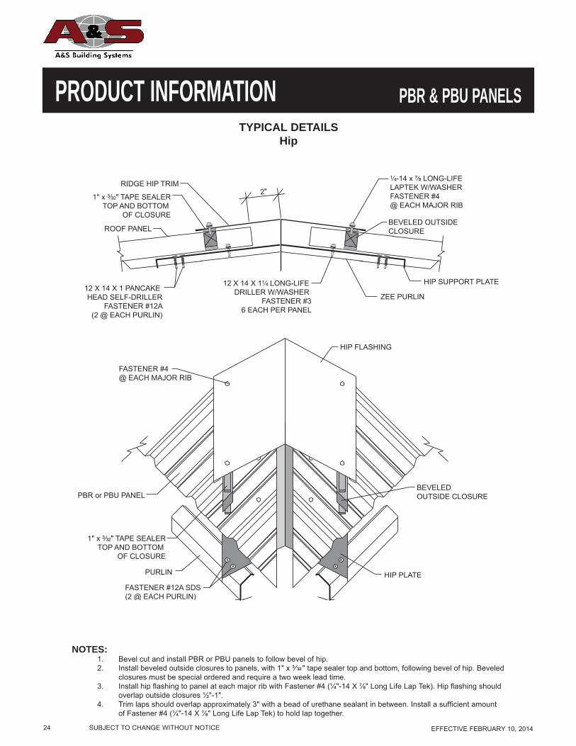
PRODUCT INFORMATIONTYPICAL DETAILS
Hip
NOTES:1. Bevel cut and install PBR or PBU panels to follow bevel of hip.2. Install beveled outside closures to panels, with 1" x ³⁄ " tape sealer top and bottom, following bevel of hip. Beveled
closures must be special ordered and require a two week lead time.3. Install hip fl ashing to panel at each major rib with Fastener #4 (¼"-14 X ⅞" Long Life Lap Tek). Hip fl ashing should
overlap outside closures ½"-1".4. Trim laps should overlap approximately 3" with a bead of urethane sealant in between. Install a suffi cient amount
of Fastener #4 (¼"-14 X ⅞" Long Life Lap Tek) to hold lap together.
ZEE PURLIN12 X 14 X 1 PANCAKE HEAD SELF-DRILLER
FASTENER #12A(2 @ EACH PURLIN)
RIDGE HIP TRIM
ROOF PANEL
HIP SUPPORT PLATE
BEVELED OUTSIDECLOSURE
HIP FLASHING
PURLIN HIP PLATE
FASTENER #4 @ EACH MAJOR RIB
BEVELED OUTSIDE CLOSURE PBR or PBU PANEL
12 X 14 X 1¹⁄₄ LONG-LIFE DRILLER W/WASHER
FASTENER #36 EACH PER PANEL
¹⁄₄-14 x ⁷⁄₈ LONG-LIFELAPTEK W/WASHER FASTENER #4 @ EACH MAJOR RIB
1" x ³⁄₃₂" TAPE SEALERTOP AND BOTTOM
OF CLOSURE
1" x ³⁄₃₂" TAPE SEALERTOP AND BOTTOM
OF CLOSURE
FASTENER #12A SDS (2 @ EACH PURLIN)
2"
PBR & PBU PANELS
SUBJECT TO CHANGE WITHOUT NOTICE EFFECTIVE FEBRUARY 10, 2014 25
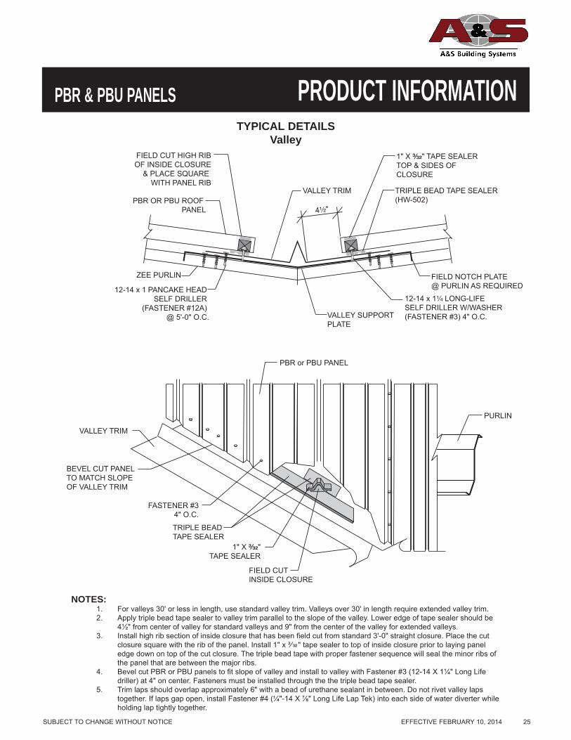
PRODUCT INFORMATIONPBR & PBU PANELSTYPICAL DETAILS
Valley
NOTES:1. For valleys 30' or less in length, use standard valley trim. Valleys over 30' in length require extended valley trim.2. Apply triple bead tape sealer to valley trim parallel to the slope of the valley. Lower edge of tape sealer should be
4½" from center of valley for standard valleys and 9" from the center of the valley for extended valleys.3. Install high rib section of inside closure that has been fi eld cut from standard 3'-0" straight closure. Place the cut
closure square with the rib of the panel. Install 1" x ³⁄ " tape sealer to top of inside closure prior to laying paneledge down on top of the cut closure. The triple bead tape with proper fastener sequence will seal the minor ribs ofthe panel that are between the major ribs.
4. Bevel cut PBR or PBU panels to fi t slope of valley and install to valley with Fastener #3 (12-14 X 1¼" Long Lifedriller) at 4" on center. Fasteners must be installed through the the triple bead tape sealer.
5. Trim laps should overlap approximately 6" with a bead of urethane sealant in between. Do not rivet valley lapstogether. If laps gap open, install Fastener #4 (¼"-14 X ⅞" Long Life Lap Tek) into each side of water diverter whileholding lap tightly together.
PURLIN
VALLEY TRIM
VALLEY SUPPORTPLATE
FIELD NOTCH PLATE@ PURLIN AS REQUIRED
VALLEY TRIMPBR OR PBU ROOF
PANEL
ZEE PURLIN
12-14 x 1¹⁄₄ LONG-LIFE SELF DRILLER W/WASHER(FASTENER #3) 4" O.C.
12-14 x 1 PANCAKE HEAD SELF DRILLER
(FASTENER #12A) @ 5'-0" O.C.
1" X ³⁄₃₂" TAPE SEALERTOP & SIDES OF CLOSURE
TRIPLE BEAD TAPE SEALER(HW-502)
FIELD CUT HIGH RIBOF INSIDE CLOSURE
& PLACE SQUARE WITH PANEL RIB
FIELD CUT INSIDE CLOSURE
PBR or PBU PANEL
FASTENER #34" O.C.
BEVEL CUT PANEL TO MATCH SLOPE OF VALLEY TRIM
TRIPLE BEAD TAPE SEALER
1" X ³⁄₃₂"TAPE SEALER
4¹⁄₂"

26 SUBJECT TO CHANGE WITHOUT NOTICE EFFECTIVE FEBRUARY 10, 2014
PRODUCT INFORMATIONTYPICAL DETAILS
Gutter
NOTES:Eave Gutter
1. Attach gutter to eave strut with two Fastener #14A pop rivets per section.2. Install inside closures to top leg of gutter with 1" x ³⁄ " tape sealer top and bottom.3. Install PBR or PBU panel with Fastener #3 (12-14 X 1¼" Long Life driller) on each side of major ribs (two fasteners per
foot). Fasteners must be installed up slope from inside closures.4. Gutter laps should be approximately 3" with a bead of urethane sealant in between. Install a suffi cient amount of pop rivets
to hold lap together.5. Install gutter straps 3'-0" on center with Fastener #4 (¼"-14 X ⅞" Long Life Lap Tek) fasteners at each end.
Hang-on Gutter1. Attach Box Panel Cap Trim to top of eave strut with pop rivet #14A (two per 10'-0" section).2. Install inside closure on top of Box Panel Cap Trim with 1" x ³⁄ " tape sealer top and bottom of closure.3. Install PBR or PBU panels with Fastener #3 (12-14 X 1¼" Long Life driller)on each side of the major ribs (two fasteners
per foot). Fasteners must be installed up slope from inside closures.4. Attach gutter to roof panels with Fastener #4 (¼"-14 X ⅞" Long Life Lap Tek) at 12" O.C.5. Gutter laps should be approximately 3" with a bead of urethane sealant in between. Install a suffi cient amount of Fastener
#14 (pop rivets) to hold lap together.6. Install gutter straps 3'-0" on center with Fastener #4 (¼"-14 X ⅞" Long Life Lap Tek) at each end.
PBR or PBU PANEL INSIDE CLOSURE
FASTENER #36 EACH PER PANEL
WALL PANEL
SCULPTUREDHANG ONGUTTER
FASTENER #4
GUTTER STRAP
FASTENER #4
1" x ³⁄₃₂"TAPE SEALER
1" x ³⁄₃₂"TAPE SEALER
BOX PANEL CAP TRIM
FASTENER #14APOP RIVET(2 PER TRIM PIECE)
INSULATION
DOUBLE FACED TAPE
EAVE STRUT
FASTENER #3(6 EACH PER PANEL)
FASTENER #14APOP RIVET(2 PER TRIM PIECE)
PBR or PBU PANEL
WALL PANEL
SCULPTUREDEAVE GUTTER
FASTENER #4GUTTER STRAP
INSIDE CLOSURE
FASTENER #4 1" x ³⁄₃₂"TAPE SEALERTOP AND BOTTOMOF CLOSURE
1³⁄₄" OR AS SPECIFIED
INSULATION
DOUBLE FACED TAPE
EAVE STRUT
1³⁄₄" OR AS SPECIFIED
FASTENER #4@ 12" O.C.
¹⁄₂" X ³⁄₃₂" TAPE SEALER
1" X ³⁄₃₂" TAPE SEALER(HW-506) TOP & BOTTOM
OF CLOSURE
INSIDE CLOSURE
BOX PANEL CAP TRIM
(HW-507) @ PANEL SIDELAP
PBR SCULPTUREDHANG ON GUTTER
PBR ROOF PANEL
PBR & PBU PANELS

SUBJECT TO CHANGE WITHOUT NOTICE EFFECTIVE FEBRUARY 10, 2014 27
PRODUCT INFORMATIONPBR & PBU PANELSTYPICAL DETAILS
Eave Trim
NOTES:1. Install eave trim to structure with two pop rivets per section.2. Install inside closures along top leg of eave trim with 1" x ³⁄ " tape sealer top and bottom.3. Install PBR or PBU panel with Fastener #3 (12-14 X 1¼" Long Life driller) on each side of major ribs (2 fasteners per
foot) allowing panel to overhang 1³⁄₄" plus wall thickness. Fasteners must be installed up slope from inside closures.4. Attach front face of eave trim to wall with fasteners or cleat as required for wall substrate.5. Trim laps should overlap approximately 3" with a bead of urethane sealant in between. Install a suffi cient amount of
Fastener #4 (¼"-14 X ⅞" Long Life Lap Tek) to hold lap together.
INSIDE CLOSURE
EAVE TRIM
DOUBLE FACED TAPE
INSULATION WITH VINYL FOLDED BACK AT EAVE
¹⁄₂" X ³⁄₃₂"TAPE SEALER
1" X ³⁄₃₂" TAPE SEALERTOP AND BOTTOMOF CLOSURE
³⁄₃₂ 1" X " TAPE SEALER (SEAL TO TAPE SEALER AT EAVE AND SIDELAP)
PBR or PBU PANEL
PBR or PBU PANEL
FASTENER #3 (6 EACH PER PANEL)
EAVE STRUT
FASTENER #4 12" O.C.
FASTENER #14A(2 PER TRIM PIECE)
FASTENER #4 20" O.C.
¹⁄₂" X ³⁄₃₂" TAPE SEALER
DETAIL "A"
SIDELAP ATTACHMENT (SEE DETAIL A)
INSIDE CLOSURE
EAVE TRIM
FASTENER #14A(2 PER TRIM PIECE)
EAVE STRUT WALL PANEL
FASTENER #3 (6 EACH PER PANEL)
FASTENER #4 12" O.C.
INSULATION
DOUBLE FACED TAPE
OUTSIDE CLOSURE
1³⁄₄" OR AS SPECIFIED
1" X ³⁄₃₂" TAPE SEALERTOP AND BOTTOM
OF CLOSURE

28 SUBJECT TO CHANGE WITHOUT NOTICE EFFECTIVE FEBRUARY 10, 2014
PRODUCT INFORMATIONTYPICAL DETAILS
Rake
NOTES:Beginning on Module
1. Install 1" x ³⁄ " tape sealer to top of PBR or PBU panel rib.2. Install rake trim to PBR or PBU panel rib with Fastener #4 (¼"-14 X ⅞" Long Life Lap Teks) at 1'-0" on center.3. Attach front face of rake trim to wall with fasteners or cleat as required for wall substrate.4. Trim laps should overlap approximately 3" with a bead of urethane sealant in between. Install a suffi cient amount of
Fastener #14 pop rivets to hold lap together.
Finishing off Module1. Cut and bend a 1" leg on PBR or PBU Panel.2. Install 1" x ³⁄ " tape sealer to top of PBR or PBU panel.3. Install rake trim to PBR or PBU panel with Fastener #4 (¼"-14 X ⅞" Long Life Lap Teks) at 6" on center.4. Attach front face of rake trim to wall with fasteners or cleat as required for wall substrate.5. Trim laps should overlap approximately 3" with a bead of urethane sealant in between. Install a suffi cient amount of
Fastener #14 pop rivets to hold lap together.
RAKE ANGLE
PURLIN
FASTENER #4 6" O.C.
FIELD BEND 1" LEG
PBR or PBU PANEL
FASTENER #4 12" O.C.
SCULPTURED RAKE TRIM
FASTENER #4 12" O.C.
1" X ³⁄₃₂"TAPE SEALER
1" X ³⁄₃₂"TAPE SEALER
OUTSIDE CLOSURE
BEGINNING ON MODULE
FINISHING OFF MODULE
FASTENER #17A EACH SUPPORT
PBR & PBU PANELS
SUBJECT TO CHANGE WITHOUT NOTICE EFFECTIVE FEBRUARY 10, 2014 29
PRODUCT INFORMATIONPBR & PBU PANELSTYPICAL DETAILS
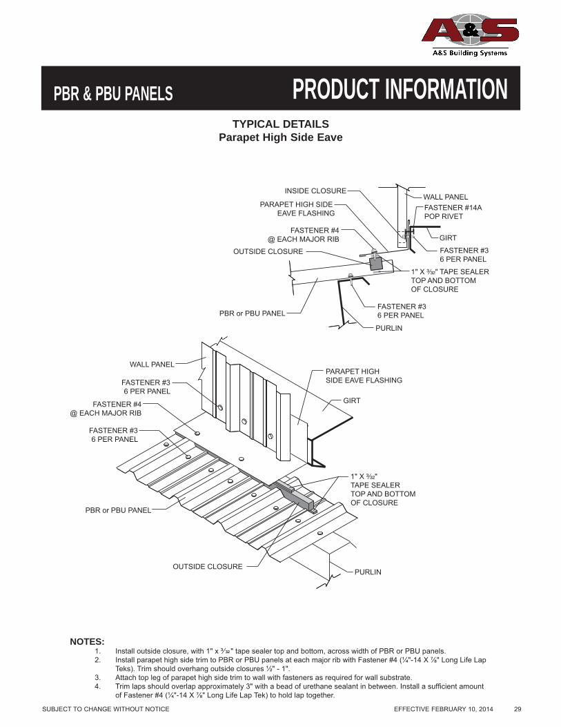
Parapet High Side Eave
NOTES:1. Install outside closure, with 1" x ³⁄ " tape sealer top and bottom, across width of PBR or PBU panels.2. Install parapet high side trim to PBR or PBU panels at each major rib with Fastener #4 (¼"-14 X ⅞" Long Life Lap
Teks). Trim should overhang outside closures ½" - 1".3. Attach top leg of parapet high side trim to wall with fasteners as required for wall substrate.4. Trim laps should overlap approximately 3" with a bead of urethane sealant in between. Install a suffi cient amount
of Fastener #4 (¼"-14 X ⅞" Long Life Lap Tek) to hold lap together.
OUTSIDE CLOSURE
FASTENER #36 PER PANEL
FASTENER #4@ EACH MAJOR RIB
WALL PANEL
GIRT
PARAPET HIGH SIDE EAVE FLASHING
PURLIN
PURLIN
FASTENER #36 PER PANEL
FASTENER #36 PER PANEL
PBR or PBU PANEL
PBR or PBU PANEL
WALL PANEL
FASTENER #4@ EACH MAJOR RIB
OUTSIDE CLOSURE
PARAPET HIGH SIDE EAVE FLASHING
1" X ³⁄₃₂" TAPE SEALERTOP AND BOTTOMOF CLOSURE
FASTENER #36 PER PANEL
INSIDE CLOSURE
GIRT
FASTENER #14APOP RIVET
1" X ³⁄₃₂"TAPE SEALERTOP AND BOTTOMOF CLOSURE

30 SUBJECT TO CHANGE WITHOUT NOTICE EFFECTIVE FEBRUARY 10, 2014
PRODUCT INFORMATIONTYPICAL DETAILS
Parapet Rake
NOTES:Beginning on Module
1. Install 1" x ³⁄ " tape sealer to top of PBR or PBU panel rib.2. Install parapet rake trim to PBR or PBU panel rib with Fastener #4 (¼"-14 X ⅞" Long Life Lap Teks) at 1'-0" on center.3. Attach top leg of parapet rake trim to 2" X 4" angle with Fastener #14A pop rivet. Elevate horizontal leg of parapet trim
slightly, to provide for positive drainage of water.4. Trim laps should overlap approximately 3" with a bead of urethane sealant in between. Install a suffi cient amount of Fastener
#4 (¼"-14 X ⅞" Long Life Lap Tek) to hold lap together.Finishing off Module
1. Cut and bend a 1" leg on PBR or PBU Panel.2. Install 1" x ³⁄ " tape sealer to top of PBR or PBU panel.3. Install parapet rake trim to PBR or PBU panel with Fastener #4 (¼"-14 X ⅞" Long Life Lap Teks) at 6" on center.4. Attach top leg of parapet rake trim to 2" X 4" angle with pop rivets. Elevate horizontal leg of parapet trim slightly, to provide for
positive drainage of water.5. Trim laps should overlap approximately 3" with a bead of urethane sealant in between. Install a suffi cient amount of Fastener
#4 (¼"-14 X ⅞" Long Life Lap Tek) to hold lap together.
PARAPET RAKE TRIM
FASTENER #17A @ EACH PURLIN
FASTENER #4 6" O.C.
FASTENER #4 12" O.C.
PBR or PBU PANEL
2" X 4" x 16 GAUGE ANGLE
FIELD BEND 1" LEG
FASTENER #14APOP RIVET(2 PER TRIM PIECE)
PURLIN
FINISHING OFF MODULE
1" X ³⁄₃₂"TAPE SEALER
FASTENER #3
INSIDE CLOSURE
BEGINNING ON MODULE
PBR & PBU PANELS

SUBJECT TO CHANGE WITHOUT NOTICE EFFECTIVE FEBRUARY 10, 2014 31
PRODUCT INFORMATIONPBR & PBU PANELSTYPICAL DETAILS
Corner
NOTES:1. Install corner trim with Fastener #4 (¼ - 14 X ⅞" Long Life Lap Tek) at 2'-0" O.C.
INSIDE CORNER DETAIL
INSIDE CORNER TRIM
WALL GIRT
FASTENER #4 24" O.C.
WALL GIRT
OUTSIDE CORNER DETAIL
PBR or PBU PANEL
PBR or PBU PANEL
OUTSIDE CORNER TRIM
FASTENER #4 24" O.C.

32 SUBJECT TO CHANGE WITHOUT NOTICE EFFECTIVE FEBRUARY 10, 2014
PRODUCT INFORMATIONTYPICAL DETAILS
Corner Box
NOTES:1. Gutter and rake trim must be ordered with a left and right mitered end. To determine left or right, stand on ground and look
toward eave. Roof slope must also be specifi ed.
PBR or PBU PANEL
SCULPTURED EAVE GUTTER (MITERED)
GUTTER STRAPS 3'-0" O.C.
PBR WALL PANEL
CORNER TRIM
SCULPTURED RAKE TRIM (MITERED)
GUTTER END
SCULPTURED EAVE GUTTER (MITERED)
SCULPTURED RAKE TRIM (MITERED)
GUTTER END
PBR & PBU PANELS

SUBJECT TO CHANGE WITHOUT NOTICE EFFECTIVE FEBRUARY 10, 2014 33
PRODUCT INFORMATIONPBR & PBU PANELSTYPICAL DETAILS
Base
NOTES:1. Wall with vinyl insulation, pull back fi berglass approximately 4" pull over end and staple. Apply double face tape to
base angle and stick insulation to it before applying panel and fastening with Fastener #3 (¼ - 14 x 1¼" Long LifeDriller), six each per panel.
2. Should base trim be desired, temporarily attach trim to base angle with two Fastener #14 pop rivets until panelsare installed.
2" x 4" BASE ANGLE
FASTENER #3 (6 PER PANEL)PBR or PBU PANEL
PBR or PBU PANEL
2" x 4" BASE ANGLE
FASTENER #3 (6 PER PANEL)
FASTENER #11 @ 3'-0" O.C.
FASTENER #11 @ 3'-0" O.C.
DOUBLE-FACED TAPE
INSULATION
DOUBLE-FACEDTAPE
INSULATION
¹⁄₄" MIN.
¹⁄₄" MIN.
BASE TRIM

34 SUBJECT TO CHANGE WITHOUT NOTICE EFFECTIVE FEBRUARY 10, 2014
PRODUCT INFORMATIONTYPICAL DETAILS
Head Jamb
NOTES:1. Install Jamb and Head Trim with pop rivets as required to support fl ashing during panel installation.
DOOR JAMB
JAMB TRIM
WALL GIRT
HEAD TRIM
GIRT
DOOR HEAD
HEAD
FASTENER #3 @ EACH GIRT
JAMB
FASTENER #17A@ 12" O.C.FASTENER #3
3'-0" O.C.
PBR or PBU PANEL
PBR or PBU PANEL
FASTENER #17A @ EACH GIRT
FASTENER #17A @ EACH GIRT
FASTENER #17A @ 12" O.C.
PBR & PBU PANELS

SUBJECT TO CHANGE WITHOUT NOTICE EFFECTIVE FEBRUARY 10, 2014 35
PRODUCT INFORMATIONPBR & PBU PANELSINSTALLATION GUIDELINES
I. Pre-Order
A. Prior to ordering panels, all dimensions should be confirmed by field measurement.
II. Job Site Storage and Handling
A. Check the shipment against the shipping list.
B. Damaged material must be noted on bill of lading.
C. Panels should be handled carefully. A spreader bar of appropriate length is
recommended for hoisting.
D. Check to see that moisture has not formed inside the bundles during shipment. If
moisture is present, panels should be wiped dry, then restacked and loosely covered
so that air can circulate between the panels.
III. Application Checklist
A. Check substructure for proper alignment and uniformity to avoid panel distortion.
B. Periodic check of panel alignment is crucial to proper panel installation.
C. For proper appearance, ribs should line up at hips, valleys and ridges.
D. Panels should be cut on ground to minimize cut filings on roof. Keep panels clean
during installation. Do not allow panels to come into contact with water runoff from
lead, copper or graphite.