PBGC Enterprise Architecture Executive Summary architecture blueprintold...PBGC Enterprise...
97
Transcript of PBGC Enterprise Architecture Executive Summary architecture blueprintold...PBGC Enterprise...
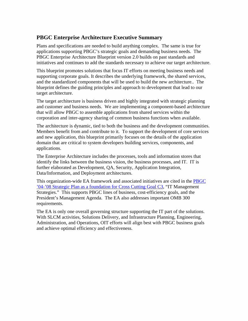
PBGC Enterprise Architecture Executive Summary Plans and specifications are needed to build anything complex. The same is true for applications supporting PBGC’s strategic goals and demanding business needs. The PBGC Enterprise Architecture Blueprint version 2.0 builds on past standards and initiatives and continues to add the standards necessary to achieve our target architecture.
This blueprint promotes solutions that focus IT efforts on meeting business needs and supporting corporate goals. It describes the underlying framework, the shared services, and the standardized components that will be used to build the new architecture.. The blueprint defines the guiding principles and approach to development that lead to our target architecture.
The target architecture is business driven and highly integrated with strategic planning and customer and business needs. We are implementing a component-based architecture that will allow PBGC to assemble applications from shared services within the corporation and inter-agency sharing of common business functions when available.
The architecture is dynamic, tied to both the business and the development communities. Members benefit from and contribute to it. To support the development of core services and new application, this blueprint primarily focuses on the details of the application domain that are critical to system developers building services, components, and applications.
The Enterprise Architecture includes the processes, tools and information stores that identify the links between the business vision, the business processes, and IT. IT is further elaborated as Development, QA, Security, Application Integration, Data/Information, and Deployment architectures.
This organization-wide EA framework and associated initiatives are cited in the PBGC ’04-’08 Strategic Plan as a foundation for Cross Cutting Goal C3, “IT Management Strategies.” This supports PBGC lines of business, cost-efficiency goals, and the President’s Management Agenda. The EA also addresses important OMB 300 requirements.
The EA is only one overall governing structure supporting the IT part of the solutions. With SLCM activities, Solutions Delivery, and Infrastructure Planning, Engineering, Administration, and Operations, OIT efforts will align best with PBGC business goals and achieve optimal efficiency and effectiveness.

1. Introduction and Overview Section
1.1 The EA Program PBGC spends $70 million annually for IT investments, including new systems, maintenance and infrastructure support. Are these resources well invested and getting a good return on investment (ROI)? Enterprise Architecture (EA) is part of the framework that enables decision makers to have confidence that the answer to this question is yes.
EA is several things. It is an organizational element in OIT. It is the program carried forward by that organization and others. It is various products delivered by that program, such as the EA roadmap and the EA blueprint and the target EA.
1.1.1 Purpose The purpose of the EA program is to ensure that IT solutions and investments align with and support the business goals of the corporation and successfully meet business needs for which they are designed. The PBGC strategic plan is the driver, identifying the corporation’s mission, vision, and values, at which IT investments must aim.
1.1.2 Goals OIT has developed several IT goals that comprise a mechanism to measure how proposed IT solutions fit (or do not fit) within the EA of PBGC. These goals are used to evaluate compliance and provide the EA staff with the necessary standard to provide guidance and feedback on IT investments. These goals are that IT investments:
• Must be able to demonstrate alignment with the business strategy and needs of the corporation
• Should be interoperable with the corporation’s systems and services • Deliver high end-user satisfaction • Should be designed in and open systems environment • Enable public access to required information in an efficient and affective
manner • Ensure compliance to pertinent federal and corporation laws, regulation,
policies, and guidelines
1.1.3 Guidelines PBGC’s EA follows a basic set of guidelines:
• Simpler is better. Supporting several different vendors’ products providing the same functionality increases costs unnecessarily.
• Commercial products should be used where possible. In general it is more cost effective to use a commercial product so that the cost of innovation is spread across multiple companies.
• Industry based standards or best practices or should be used when available. The use of industry standards increases the robustness of the standard and

reduces time and costs for PBGC to adopt that standard. (NIST, World Wide Web Consortium (W3C), Java Community)
• The architectural design must consider and address the needs of the entire Corporation.
• The architectural design must be modular and extensible allowing for new technologies and configurations to be deployed with minimal costs and impact.
• Build it once. Don’t reinvent functionality. Common needs should be met by constructing and using common services.
• There is a single source for enterprise data. Data integrity is maintained by allowing only a single component to operate on specific data.
1.1.4 Benefits The EA uses the PBGC strategic plan to identify how IT investments align and support the corporation’s mission, vision, and values. The EA provides oversight via reviews of business cases and technical documents to ensure that IT investments and solution delivery remain aligned with their business drivers.
Other benefits that an EA program provides to PBGC include developing and documenting a roadmap that sets standards and guidelines for future IT solutions development. Also, EA fosters the development of common IT services and reuse of IT resources to maximize the ROI of the corporation’s investments. An EA program also promotes interoperability of IT systems and solutions. And finally, the corporation is required to develop and implement an EA program through Federal laws, policies, and guidelines.
1.1.5 EA Blueprint The EA blueprint is a set of documents and information presented in the corporate portal that explains the PBGC target Enterprise Architecture. It provides more detail than the previously published EA roadmap. It is intended to guide developers of PBGC applications to ensure that their efforts hit the targets established in the business process, data, applications and infrastructure architecture domains. It provides a set of standards based on industry best-practices and technical solutions that meet the goals of the EA, provide an optimum ROI, and allow the corporation to transition to the target architecture.
The PBGC EA is a framework developed around the implementation of IT standards and processes. The EA staff is responsible for the development and publication of these standards.
The IT world is in constant flux as new technologies, products, and solutions are developed and introduced. The EA blueprint adapts to these changes in a controlled way. It guides IT investment to realize the benefits of improved technology and best practices when they can have a positive impact on ROI. The EA blueprint is a living document, responsive to market and organizational changes. See the EA Program and Processes Section for information about the processes by which EA blueprint is managed and maintained.

The PBGC target architecture is a services oriented architecture (SOA). This architecture fosters the development of common IT services and reuse of IT resources to maximize the ROI of the corporation’s investments. It also promotes interoperability of IT systems and solutions, reducing the investment required for PBGC business to work together collaboratively and efficiently. The Common Services Section of the blueprint provides additional description of the SOA and how it is implemented in PBGC. Technical standards covering the SOA are found in the Applications Domain Section and the Infrastructure Domain Section of the blueprint.
1.2 Organization of the Blueprint as a Whole The EA blueprint is a set of documents and information presented in the EA Blueprint Publication on the corporate portal. There are diagrams, text documents and databases, open to browse, with a search function, and with numerous built in internal links for navigational convenience. It also contains links to other documents or to other sites where relevant information is found. A selection of the information on the portal, unified into a single PDF document, is available on the portal and on the intranet and may sometimes be put on slides for presentation or printed for paper distribution. However, as it is a living document, the portal is the preferred means of access.
The sections of the blueprint (found in document sub-folders on the portal) are:
Section Information Found In That Section 1. Introduction and Overview Section
General description of the EA blueprint document; its structure, and scope, target audience and applicability; how to navigate, and links to other sections. The paragraphs below provide additional information about this section.
2. EA Program and Processes Section
Describes processes for maintaining the EA blueprint: how to suggest changes; how to request exceptions; and how to get answers to questions.
3. Business Process Domain Section
Describes an architectural framework identifying, grouping and organizing PBGC processes. Includes the PBGC business structure and references EA standards for defining, modeling, and documenting business processes, and tools supporting process modeling.
4. Data Domain Section
Describes the life cycle of data including acquisition, cleansing, transactional, through reporting and analytics. Concepts are shown including the separation of data based on the function operating on the data.
5. Applications Domain Section
Describes in detail PBGC’s services oriented architecture along with the deployment model using Java and Oracle’s application server.
6. Infrastructure Domain Section
Describes the technology infrastructure required to support the applications that are developed to meet the business needs of PBGC as well as the core network services (e.g. E-mail, Internet access,
LAN/WAN, cable plant, network protocols, data storage and backup, etc) needed to provide connectivity to internal and external customers of the corporation’s IT services and resources.
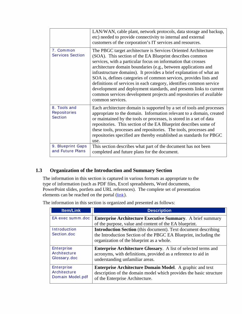
7. Common Services Section
The PBGC target architecture is Services Oriented Architecture (SOA). This section of the EA Blueprint describes common services, with a particular focus on information that crosses architecture domain boundaries (e.g., between applications and infrastructure domains). It provides a brief explanation of what an SOA is, defines categories of common services, provides lists and definitions of services in each category, identifies common service development and deployment standards, and presents links to current common services development projects and repositories of available common services.
8. Tools and Repositories Section
Each architecture domain is supported by a set of tools and processes appropriate to the domain. Information relevant to a domain, created or maintained by the tools or processes, is stored in a set of data repositories. This section of the EA Blueprint describes some of these tools, processes and repositories. The tools, processes and repositories specified are thereby established as standards for PBGC use.
9. Blueprint Gaps and Future Plans
This section describes what part of the document has not been completed and future plans for the document.
1.3 Organization of the Introduction and Summary Section The information in this section is captured in various formats as appropriate to the type of information (such as PDF files, Excel spreadsheets, Word documents, PowerPoint slides, portlets and URL references). The complete set of presentation elements can be reached on the portal (link).
The information in this section is organized and presented as follows: Item/Link Description
EA exec summ.doc Enterprise Architecture Executive Summary. A brief summary of the purpose, value and content of the EA blueprint.
Introduction Section.doc
Introduction Section (this document). Text document describing the Introduction Section of the PBGC EA Blueprint, including the organization of the blueprint as a whole.
Enterprise Architecture Glossary.doc
Enterprise Architecture Glossary. A list of selected terms and acronyms, with definitions, provided as a reference to aid in understanding unfamiliar areas.
Enterprise Architecture Domain Model.pdf
Enterprise Architecture Domain Model. A graphic and text description of the domain model which provides the basic structure of the Enterprise Architecture.

Enterprise Architecture Graphic View
Enterprise Architecture Graphic View. A graphical representation of some of the elements of the PBGC Enterprise Architecture, with links. See section 1.6 below for more information.
EA Detailed Standards.doc
EA Detailed Standards. This blueprint specifies numerous standards in the graphic and text documents. Selected standards have been elaborated in additional stand-alone documents describing them in greater detail. This document lists and provides links to the additional detailed documents for those selected standards.
(future) Frequently Asked Questions. Access to questions previously asked and answers provided concerning the EA blueprint.
1.4 Enterprise Architecture Domain Model A key to understanding the corporation’s EA framework is the Domain Model, which structures the target architecture. The Domain Model is comprised of six distinct domains, or parts, that are interrelated, and, together, show the progression of business and strategic needs driving IT solutions. The various EA architecture components are organized around these domains.
The Domain Model has six domains, described briefly in the following table. A graphic view and additional explanation of the domain model is found in the document Enterprise Architecture Domain Model.pdf in the introduction section of the blueprint. The architecture and standards applicable to each domain are found in the corresponding sections of the blueprint (links in the table below).
Domain Description Business Processes
The Business Process Domain describes the EA from the point of view of the business requirements, which are derived from strategic plans and business goals. This section describes the architecture standards for business process analysis.
Data The Data Domain describes the EA from the point of view of the data, which are inputs to and outputs from the Business Model. Architecture standards in this section cover naming conventions and structuring to ensure consistent shared data across the organization.
Skills and Organization
The Skills and Organization Domain describes the work and activities needed to perform and control business processes that the Corporation needs. Business processes determine the skills and organization needed . Enterprise architecture models and standards have not yet been developed for this domain.
Applications The Applications Domain describes the flow of activities encompassed by business processes. Business processes also determine what must be done to the data by applications. . Architectures in this section are the most fully developed and provide standards and guidance for the developers to ensure interoperable

applications built with minimum redundancy and maximum re-use. Technology Infrastructure
The Technology Infrastructure Domain describes how, applications and data requirements drive the technology infrastructure that provides the platforms on which databases and applications run. Architectures in this section provide standards and direction for the infrastructure.
Facilities The Facility Domain describes facility requirements for housing the organization and infrastructure based on business processes. Enterprise architecture models and standards have not yet been developed for this domain.
1.5 Enterprise Architecture Graphic View Figure 1-2 depicts at a high level the relationship of Enterprise Architecture to its business drivers and also the major elements of the Enterprise Architecture.

1.3) IT Architecture:
1.2) Business Architecture:
1.1) Business Vision:
Enterprise Architecture
BusinessStrategy &
RulesBusiness
Goals
Information
Integration
Application
PensionInsurance
PlanTermination
OperationalSupport
PBGC GoalsGoal 1 - Protect existing benefit plans and theirparticipants, and thereby encourage new plans.Goal 2 - Provide high-quality, responsive servicesand accurate and timely payment of benefits toparticipants.Goal 3 - Strengthen financial programs and systemsto keep the pension insurance system solvent.Goal 4 - Improve internal management supportoperations.
GOAL: Encourage a stable, adequatelyfunded system of private pension plans.Key Performance Indicators:
Stable and Solvent Insurance SystemEarly WarningInvestment ManagementPractitioner Servicese-Gov for Practitioners
GOAL: Provide responsive, timely and accurateservices to participants in trusteed plans.Key Performance Indicators:
Timely benefit estimates to ParticipantsTimely Acknowledgement of ParticipantsContactsTimely and Accurate Benefit ProcessingTimely Appeals Processinge-Gov for participant/missing participants
Security
Common Services
Infrastructure
Data
Dev
elop
men
tQ
uality Assurance
Tool
sRe
posi
torie
sA
rtifa
ctR
elat
ions
hips
Serv
ice
Def
icie
ncy
Res
olut
ion
Application Network
PortalLink
Message
Perfo
rman
ce M
onito
ring
and
Repo
rting

There are three levels:
The Business Vision (1.1) indicates that strategy and goals established in the corporate business vision are the driving force which controls the architecture.
Business Architecture (1.2) is derived from Business Vision. It shows the three lines of business (Pension Insurance, Plan Termination and Operational Support) established by the business vision for PBGC.
IT Architecture (1.3) is implemented based on the design of the Business Architecture.
These and other elements depicted in the diagram are described in the paragraphs below:
1.5.1 Business Vision The business vision of the EA framework represents the mission, vision, values, and goals of PBGC as well as the Corporation’s strategic plan and the corresponding strategic planning framework. This is also the EA layer where the business drivers that own IT investments are defined and derived from, usually in the form of supporting outcome goals and strategic initiatives.
1.5.2 Business Architecture The business architecture layer of the EA framework represents the three business areas of PBGC and includes 1) Pension Insurance, 2) Plan Termination, and 3) Operational Support. Included in this layer are the business processes and functions that each business area requires and owns to carry out the tasks and meet the goals of that area.
1.5.3 IT Architecture The IT architecture of the EA framework represents the components that provide for the development, implementation, and management the IT investments. Within each of these elements are found the technical solutions and standards required to develop systems and services within the PBGC EA framework.
Inside the IT Architecture block several elements are identified. Each of these elements is also a hyperlink to another page of the graphic where those elements are presented in greater detail. The architecture elements depicted in this block are security, application, integration, service, information, deployment, and infrastructure. Another block to the side depicts supporting elements, which are processes, tools, repositories and artifact relationships.1.6 Frequently Asked Questions
In the future, a repository of questions asked and answered will be exposed here. At this time, no questions have been raised, nor has it been determined what repository type will store and display this information. When questions are raised in the future, they will be answered, captured, and exposed on the EA Blueprint portal.

1.7 EA Detailed Standards This section lists and provides links to the additional detailed documents for those standards which have been selected for detailed explanations. The EA blueprint specifies numerous standards in the graphic and text documents. For instance, as shown in Figure 1-1, the Applications Architecture diagram in the Enterprise Architecture Graphic View indicates that our standard Model-View-Controller (MVC) implementation is Struts 2.0.
Figure 1-2: Selection from Applications Architecture diagram, showing MVC in the
middle
While this is a standard, it is clear from Figure 1-1 that there is not a lot of information provided about this standard. Therefore, selected standards have been elaborated in additional stand-alone documents describing them in greater detail. For instance, the document “Standards Profile - Presentation Layer - Architecture.doc” was prepared in April 2003, describes the MVC (model-view-controller) architecture, and provides the rationale as to why this standard was selected. Figure 1-2 shows just the introduction; click the link above to read the entire document.
Profile Information
Title: Presentation Layer– Software Architecture Number:
Revision Number: 1.0 Origin Date: 01 APRIL 2003
Revision Date: 30 APRIL 2003 Revision Status: Final
TRM Location: Presentation Layer
Description: This SP deals with the software architecture recommendations for the

presentation layer
Figure 1-3: Introductory information from the Standards Profile - Presentation Layer - Architecture.doc
1.7.1 A Standard is still a Standard, Even if it is not a Detailed Standard Most of the standards which are depicted in the diagrams are described briefly in the text document in each blueprint section, even if they have not been selected for further explanation in a detailed standard. For instance, figure 1-3 is taken from the text document “Applications Domain Section.doc” describing the graphic presentation of standards in the applications domain section.
• Struts, an MVC2 implementation - Struts is a set of cooperating classes, servlets, and JSP tags that make up a reusable MVC 2 design. This definition implies that Struts is a framework, rather than a library, but Struts also contains an extensive tag library and utility classes that work independently of the framework.
Figure 1-4: Selection from Applications Domain Section.doc
Note that items depicted in the diagrams, such as the “MVC: Struts 2.0” example above, are EA standards. They are standards even if there is no further explanation in the companion text document. They are standards even if there is no standalone detailed standards document on the same topic.
1.7.2 Detailed Standards List and Links Detailed Standard Section Description
Browser Support Guidelines for Web Based Applications.doc
Application Specifies browser version PBGC applications must support
Logical Model Metadata and Naming Standards.doc
Data Defines the standards for logical data model naming and metadata for use by designers and developers
PBGC Corporate Naming
Data Specifies naming standards for PBGC data elements

Standards.doc
PBGC Intranet User Interface Guidelines.doc
Application Specifies standard set of views into PBGC data and components that have the same look and feel for PBGC applications
PBGC J2EE Session Management Standard.doc
Application Standard method that all PBGC J2EE web based applications will use when creating, managing and destroying server maintained sessions of web applications
PBGC Physical Model Standards.doc
Data Standards for naming, and object abbreviation methods for physical data models for designers and developers at PBGC
PBGC Software Component Interaction Standards.doc
Application Interaction standards for java archives, .net assemblies, and services at a URI and accessible through SOAP or RMI interface
PBGC Software Configuration Management Plan for Reuse.doc
Application Establishes a reuse framework, including existing component harvesting and re-packaging, asset identification and certification for reuse, asset certification requirements, component library and CM process
Performance Guidelines for Web Based Applications.doc
Application Specifies expected performance (screen response time) for web-based applications at PBGC
Process Model Standard Profile.doc
Business Process
Specifies information on collecting information about PBGC business processes, and general business process analysis modeling metadata and standards
PBGC Business Process Modeling Standards.doc
Business Process
Specifies standards and guidelines for business process modeling conventions and metadata (descriptions and properties)
Project Model Management.doc
Data Business Process
Specifies the process that controls and monitors the creation, modification and deletion of data and process models and the interactions among those models
Standards Profile - Presentation Layer - Architecture.doc
Application Describes model-view-controller UI architecture and why it is selected for PBGC SOA
Standards Profile - Presentation Layer - Portal Concept.doc
Application Describes target architecture for unifying PBGC workers desktop in the portal as presentation UI of SOA

Standards Profile - Presentation Layer - Technology.doc
Application Specifies programming technology for custom UI development
Standards Profile - Security Architecture.doc
Application Specifies application security architecture
Standards Profile - System Development.doc
Application Executive summary of established standards for technology stack

1.8 Support The person assigned to maintain this section is Kirby Sutton. You may ask questions or make suggestions concerning this section to him at x6602 or by e-mail at [email protected], or by contacting any Enterprise Architect. Also see the Program and Process Section of the EA blueprint.
Version Date Description
1.0 on July xx, 2004 Initial release version

2. Processes
2.1 Introduction EA is several things. It is an organizational element in OIT. It is the program carried forward by that organization and others. It is various products delivered by that program, such as the EA roadmap and the EA blueprint and the target EA. This document describes in detail information, also shown in graphic view, of selected processes which are part of the EA program. These processes are how the EA group and others (primarily OIT) create, maintain, and update standards and the EA blueprint. The EA blueprint and standards are applicable to the Process, Data, Applications and Infrastructure Domains. The information in this section is captured in various formats as appropriate to the type of information (such as PDF files, Excel spreadsheets, Word documents, PowerPoint slides, portlets and URL references). The complete set of presentation elements can be reached on the portal (link). The information in this section is organized and presented as follows:
Item/Link Description Program and Processes Section.doc
Program and Processes Section: Text document describing the Program and Processes Section of the PBGC EA Blueprint, including program goals and processes.
Standards Implementation Plan.doc
EA Standards Implementation Plan: This document describes the 90 -day plan for implementing EA standards.
Training Plan.doc (future) Frequently Asked Questions: Access to questions previously
asked and answers provided concerning the EA blueprint.
2.2 Overview of Standards and Blueprint Maintenance Processes This section describes five processes: • 2.3 The Intake Process • 2.4 The Moderate/Small Scope Blueprint or Standard Change Process • 2.5 The Waiver from Standards Compliance Process • 2.6 The Create Standard/Major Blueprint Change Process • 2.7 The Question/Suggestion/Comment Process
The intake process is the common start point of all four of the remaining processes. Part of the intake process is an evaluation of the incoming item to determine which of the other four processes should be applied. Additional processes to be drafted are listed in section 2.8 Pending Edits.

2.3 The Intake Process 2.3.1 Triggers
All processes begin with an external trigger. The intake process records the external trigger and starts the appropriate process. The external trigger may occur with an EA architect or with someone else. Triggers that may occur with an EA architect include: • Recognition that the PBGC strategic plan implies a change is needed in the
blueprint/standards • Recognition that a technology or best practice seen may be beneficial to PBGC • Recognition of an error or omission or clarification needed in the blueprint/standards (based
on own review or based on seeing patterns in questions received) Triggers that may occur with someone else include: • Confusion about, question on, or suggestion for content or presentation of
blueprint/standards • Motivation not to comply with a standard • Desire to use a technology or practice which may be beneficial to a project
Triggers originating outside of EA may often originate with an OIT manager, project manager, or infrastructure support, or with contractors and business area staff and management.
2.3.2 Portal Form It will be mandatory for OIT employees and contractors to use the portal form to start the intake process. Some business unit employees, such as those who meet regularly with OIT customer-facing units, may be given access to the portal form. Should these business unit employees wish to initiate an item, they may do so using the form. They may also use alternate means (phone call, e-mail, paper memo, or personal visit) to communicate with an OIT employee. In that case the OIT employee will record the item in the portal form for the business unit employee. The portal form will include a radio button for selecting among the types of item: • Request change to blueprint/standard • Request waiver from standard • Question • Comment • Suggestion • Other
Depending on the type selected, the form will provide various mandatory or optional fields.
Change or Waiver Request Forms Any change or waiver request will require or allow the following fields to be entered:
Field Type of Control Used Mandatory or Optional Domain Drop-down box Mandatory Architecture document for which the request is relevant
Drop-down box Mandatory

Description Field Mandatory Reason Field Mandatory Notes Field Optional
Question, Comment, or Suggestion Forms The forms for questions, comments and suggestions will have similar formats. The primary difference between them is the name of the primary text field: either “question”, “comment” or “suggestion”. The drop down lists identifying the domain and architecture document will be available but optional. The reason and notes fields will also be available but optional.
Field Type of Control Used Mandatory or Optional Domain Drop-down box Optional Architecture document for which the request is relevant
Drop-down box Optional
Description Field Mandatory Reason Field Optional Notes Field Optional
2.3.3 Task Assignment Submitting the form places the item in the EA task database and generates a task in the portal. One of the EA architects will self-assign the task. If it is not assigned within 3 days, it will elevate to the Chief Architect. If it is still not assigned after 5 more days, it will elevate to the CTO. The Chief Architect may also cancel the item and communicate the reasons with the originator. Items in the intake process are visible to the initiator, all the architects, the Chief Architect, the Deputy CTOs, and the CTO. Only the architects will be notified, unless the task assignment is elevated.
2.3.4 Review, Evaluation, and Treatment The architect assigned will review the item, and may contact the originator for clarification and additional information if necessary. The architect then evaluates the item to determine whether it should be treated as a change request, waiver request, question, comment, or suggestion. If it is a change, the architect will also evaluate the scope, which determines which process to use. Distinctions are based on the following conditions
Conditions Treatment Item may result in editorial change OROrganizational change OR Presentation in a blueprint or standard AND Item does not change substantive content
Treat as suggestion or comment
Item may result in change to substance of a blueprint or standard AND Scope is small enough for impact analysis and implementation planning
Treat as moderate/small scope blueprint or standard change

be done by EA architect Item may result in change to substance of a blueprint or standard AND Scope of which is such that impact analysis and implementation planning will require significant OIT or other resources outside of EA
Treat as create standard/major blueprint change
Originator needs clarification of item Treat as question
2.3.5 Update EA Task Database Having determined the type of item, the architect updates the EA task database accordingly. This is the end of the intake process, and triggers one of the other four processes.
2.4 The Moderate/Small Scope Blueprint or Standard Change Process This process is initiated when the intake process evaluation determines that the scope of a change request is small or moderate. The architect assigned is usually the same one who performed the intake process; however, but responsibility for an item may be transferred to another architect. The assigned architect establishes a schedule for the item and notifies the initiator. Once scheduled, items are visible to all OIT; however, the architects, the Chief Architect, OIT managers, deputy CTOs, and the CTO receive positive notice of the items to be changed.. Anyone in OIT may request inclusion in the architects’ notification group to be informed of events and activities as they occur. The architect performs research as needed, discusses the item with appropriate stakeholders and records the results of research and discussion with the item in the portal. Upon conclusion, the architect will recommend disposition of the item (make no change, or what change to make) to the Chief Architect. The Chief Architect will determine, based on the significance of the item, what the approval process will be. The approval process is based on the magnitude or effect of the change:
Magnitude Steps in Process Editorial or very minor changes
Make the change and notify CTO and Deputies
Substantive but non-controversial or low-impact changes
Notify CTO and Deputies; make change official one week later if no countermanding communication
Controversial or high-impact changes
Meet with CTO and Deputies to decide what the approval process will be and who will be involved
After approval, the architect will update the blueprint and/or relevant detailed standards and publish on the portal. Everyone who has subscribed to the updated documents will be automatically notified.

2.5 The Waiver from Standards Compliance Process This process is initiated when the intake process evaluation determines a waiver approval or denial, rather than a change to a blueprint or standard, is the appropriate response. It will normally be completed within 5 days, or the task waiver will be elevated to the Chief Architect. If still not completed within 5 more days, it will elevate to the CTO. The Chief Architect may establish a longer schedule, notifying the requestor and the CTO and publishing the revised schedule on the portal. The architect assigned is usually the same one who performed the intake process. However, responsibility for an item may be transferred to another architect. The assigned architect performs research as needed, discusses the item with appropriate stakeholders, and records the results of research and discussion with the item in the portal. Upon conclusion, the architect will recommend disposition of the item (grant waiver, or deny waiver) to the Chief Architect. The Chief Architect will determine, based on the significance of the item and the results of research and discussion, what the approval process will be. There are several outcomes based on the whether the waiver was granted or not and, if not, if the requestor is satisfied with the result:
Conditions Steps in Process Waiver rejected and requestor satisfied with result
Chief Architect denies waiver and notifies CTO and Deputies of the results
Waiver rejected and requestor dissatisfied with result
Chief Architect notifies CTO and Deputies of intention to deny, waits 1 week and then issues denial if no countermanding communication
Waiver granted Chief Architect requests approval of waiver from CTO (and notifies Deputies), CTO either directs Chief Architect to grant the waiver or provides instructions to the contrary
After grant or denial, the architect will record the result on the portal, exposing it with a link from the relevant portion of the blueprint and/or relevant detailed standards. Everyone who has subscribed to the updated documents will be automatically notified.
2.6 The Create Standard/Major Blueprint Change Process
This process is initiated when the result of the Intake Process evaluation determines that a change request would, if implemented, have major effects on the system. In this case, significant resources outside of the EA group would be needed to analyze the impact and plan the implementation of the change. A hypothetical example would be a change in relational database standards from Oracle to SQL Server of Sybase. The most important feature of this process is the explicit role for stakeholders outside the EA group. Stakeholders are involved in every phase of this process. The three major phases are: Research technology and options Develop standards document Develop implementation plan

There is no pre-established timeline for this process, but the schedule is established for each such topic on a case by case basis.
2.6.1 Research Technology and Options
In the Research Technology and Options phase, there are four steps: Step Action Performed by 1 Determine research scope 2 Perform research and analysis Assigned authors, normally
stakeholders outside of EA 3 Solicit recommendations 4 Develop standards task plan
In the Solicit Recommendations step, the initial research results are published provided to stakeholders and stakeholder recommendations are solicited. Stakeholder recommendations are expected to affect additional research or the development of the standards task plan for the next phase.
2.6.2 Develop Standards Document In the Develop Standards Document phase there are four steps:
Step Action Performed By 1 Develop Draft Standards Assigned author, normally a
stakeholder outside EA 2 Review by Federal Management Various OIT organization
elements; may include other stakeholders
3 Revise Standards Document Assigned author, normally a stakeholder outside EA
4 Review by CTO
2.6.3 Develop Implementation Plan
In the Develop Implementation Plan Phase there are four steps, one of which has three parts: Step Action Performed by 1. Write Implementation Plan Assigned author, normally a
stakeholder outside EA 1.1 Determine Training Requirements 1.2 Determine Licensing Requirements 1.3 Establish Rollout Schedule 2. Review Implementation Plan Author inside OIT 3. Publish Implementation Plan EA 4. Conduct Rollout Assigned author, normally a
stakeholder outside EA

2.7 The Question/Suggestion/Comment Process This process is initiated when the intake process evaluation determines that the incoming item can be handled without immediate change to the blueprint or standard. It may often be completed almost immediately and will almost always be completed within five 5 days. If not, the task will be elevated to the Chief Architect. If still not completed within five 5 more days, it will elevate to the CTO. Note there is one sequence that results in an item not completing the intake process. Intake may start with a channel other than portal form (e-mail, personal visit or phone call). The architect receiving the input may immediately recognize that the item is a question, not a request for waiver or other type of item. The architect then may be able to answer the question immediately. Then the architect may decide that the question and answer are not new and do not need documentation. As a result, this item will not complete the intake process, but will have completed the question/suggestion/comment process. The architect assigned is usually the same one who performed the intake process, but responsibility for an item may be transferred to another architect. If it is a difficult question or suggestion that needs analysis, the architect will establish a schedule and notify the initiator. After completing any necessary research and analysis, the architect will determine whether approval is needed. If the answer or response to suggestion or comment is fully consistent with previously published architecture, does not raise any controversial issues and will not significantly change the activities or resources expended by the initiator, architects or others, the architect will simply record the resolution. If it extends the previously published architecture but does not raise controversy or have a significant resource impact, the architect will record the resolution and notify the other architects. If the item raises controversy or has a significant resource impact, the architect will submit it to the chief architect to determine what approval will be applied.
2.8 Pending Edits Process changes to the five processes described above will be determined based on review by OIT managers. After approval of the processes, they will be fully documented per EA process analysis standards. Additional processes will be developed for approval as priorities dictate. Processes identified to date are: • Technical Design Review process, including description of criteria. An example of a
criterion is design value of performance measurement in support of strategic planning approach.
• Other EA activities at SLCM phase reviews. • Maintenance of the EA information on the public-facing internet site where vendors who
want to suggest/sell and bidders who must comply find EA information.
2.9 Frequently Asked Questions In the future, a repository of questions asked and answered will be exposed here. At this time, no questions have been raised, nor has it been determined what repository type will store and display this information. When questions are raised in the future, they will be answered, then captured and exposed on the EA Blueprint portal.
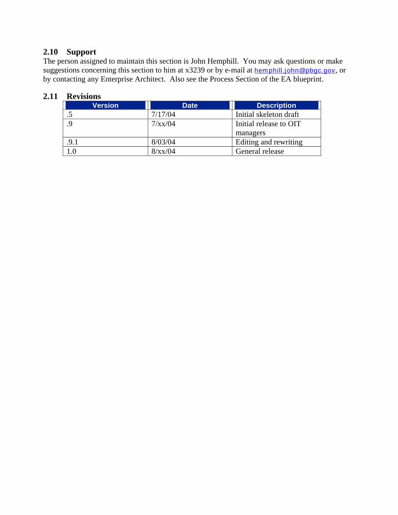
2.10 Support The person assigned to maintain this section is John Hemphill. You may ask questions or make suggestions concerning this section to him at x3239 or by e-mail at [email protected], or by contacting any Enterprise Architect. Also see the Process Section of the EA blueprint.
2.11 Revisions Version Date Description
.5 7/17/04 Initial skeleton draft
.9 7/xx/04 Initial release to OIT managers
.9.1 8/03/04 Editing and rewriting 1.0 8/xx/04 General release

Enterprise Architecture Standards Development EA_STD_PM_V1.0
Develop Enterprise Architecture Standard Develop Enterprise Architecture Standard 07/19/2004 4:36 PM
NewTechnologyAcquired
As-Is EA Model
Existing Standards
TechnologyForums
OITRequest
New Standard
IndustryBestPractices
Portal
Project Team Recommendations
Industry Best Practices
EAGuidance
SLCMRequirement
VendorPublications
OITOrganizations
EARequirement
EA Guidance
FinancialResources
OtherStakeholders
Project TeamRecommendations
0
�������������� ������������
������

Enterprise Architecture Standards Development 07/19/2004 4:36 PM
EA_STD_PM_V1.0 Develop Enterprise Architecture Standard
ApprovedStandard
NewTechnologyAcquired
SLCMRequirement
Project TeamRecommendations
Industry BestPractices
Portal
TechnologyForums
NewStandardin CM
VendorPublications
DraftImpactList
ProposedStandard
EAGuidance
OtherStakeholders
EA Guidance
Exception Request
OITOrganizations
New Requirement
As-Is EA Model
Existing Standards
FinancialResources
OITRequest
IndustryBestPractices
EARequirement
Portal
Project TeamRecommendations
1
�� ���������������
�������
2
��������������
������
3
�������
����������
���
4
������
���������

Enterprise Architecture Standards Development 07/19/2004 4:36 PM
EA_STD_PM_V1.0 Research Technology and Options
InitiateStandardsDevelopment Initial
ResearchCompleted
ScopeImpacted
CommentsReceived
ScopeImpacted
1
DetermineResearch Scope
2
Perform Researchand Analysis
3
SolicitRecommendations
4
Develop StandardsTask Plan
X
J1
EA Guidance
As-Is EAModel
EARequirement
SLCMRequirement
Project TeamRecommendations
ExistingStandards
Industry BestPractices
TechnologyForums
VendorPublications
OITOrganizations
X
J2
OtherStakeholders
EA Guidance
DraftScope
DraftStandardOutline
RefinedDraftStandardOutline

Enterprise Architecture Standards Development 07/19/2004 4:36 PM
EA_STD_PM_V1.0 Determine Research Scope
31
Define Scope ofResearch
32
Assign Research
33
Plan Research

Enterprise Architecture Standards Development 07/19/2004 4:36 PM
EA_STD_PM_V1.0 Develop Standards Document
SecondDraft
Approved Standard
Revisions
Approved Standard- SW Tools
9
Develop DraftStandard
10
Federal ManagementReview
11
Revise StandardsDocument
12
CTO Review
EA Guidance
Draft StandardOutline
Assigned Authors
OITOrganizations
Project TeamRecommendations
XJ4
OtherStakeholders
PublishDraftStandard
ReviewComments Go to
DevelopImplementationPlan
Go toConductRollout
Approve/Disapprove

Enterprise Architecture Standards Development 07/19/2004 4:36 PM
EA_STD_PM_V1.0 Develop Implementation Plan
Approved Standard
ApprovedStandard -SW Tools
27
DetermineLicensing
Requirements
17
Establish RolloutSchedule
16
Determine TrainingRequirements
18
WriteImplementation
Plan
20
ReviewImplementation
Plan
21
PublishImplementation
Plan
22
Conduct Rollout
Vendor
&J3
EAGuidance
EARequirement
SLCMRequirement
ProjectSchedules
AssignedAuthors
OITOrganizations
FinancialResources
Portal
OITOrganizations
&J5
SLCM
OITOrganizations
Training and LicenseRequirements
DraftRolloutSchedule
DraftImplementationPlan
FinalImplementationPlan
DistributePlan to AffectedParties

3. Waiver process
EA blueprint processes07/18/04 p. 3 of 5
architectresearches,discusses,
records results
architectrecommendsdisposition
Chief Architectapproveschange
architectpublishes
documentationas appropriate
database (discussions,drafts, database, task status,etc.) is open to all architects,CTO & deputies, initiator andothers as determined byarchitect; only those selectedby architect are providedongoing active notification
if exception accepted,document rationale; ifrejected, document rationaleand alternative course(s)identified
determineapprovalprocess
Approval processby CTO, deputies,or others may besimple/elaborate
request complete
if rejected and requestor issatisfied, notify CTO/deputies; if rejected andrequestor is dissatisfied,notify CTO/deputies and waitone week; if accepted, CTO/deputies must approve
fromintake
process
EA taskdatabase
EA taskdatabase

2. Moderate/small scope blueprint or standard change process
EA blueprint processes07/18/04 p. 2 of 5
architectestablish
schedule andnotify initiator
architectresearches,discusses,
records results
architectrecommendsdisposition
Chief Architectapproveschange
architectupdatesblueprint
EA taskdatabase
database (discussions,drafts, database, task status,etc.) is open to all architects,CTO & deputies, initiator andothers as determined byarchitect; only those selectedby architect are provided on-going active notification
if no change recommended,document rationale; ifchange recommended, resultis complete text of adds orchanges or scope of delete
de minimis oreditorial?
determine whetherchange requiresmore approvals,and by whom Approval process
by CTO, deputies,or others may besimple/elaborate
change complete
if de minimis, notify CTO &deputies and make change;if normal, notify CTO & deputies,wait 1 week & make change;if exceptional, meet with CTO anddeputies to plan approval process
fromintake
process
EA taskdatabase
EA taskdatabase

1. EA intake process
EA blueprint processes07/18/04 p. 1 of 5
external trigger
EA taskdatabase
enter idea orrequest intodatabase byportal form
EA architectself-assigns
task based onarea affected
auto generate EAintake task on entry
someone (developer, OITmanager, engineer, businessunit, etc.) has a question,suggestion, or comment on,perceived need to change, ordoes not wish to comply with,the EA blueprint or standard
EA taskdatabase
EA taskdatabase
automatically route andelevate to Chief Architect ifnot assigned within 3 days
selectsubmission
channel
othermeans
portalform
architect enters
determineappropriate
process
mod.sm.change waiver question
sug.cmt.
create/major
change
The architect evaluates theintake task to determine whichprocess to apply, and may alsodiscuss with submitter andupdate task submitted withadditional clarifying information
external trigger
Architect may self-initiate anitem based on evaluation ofPBGC strategic plan, marketor technology events or othertrigger internal to EA

5. Question/suggestion/comment process
EA blueprint processes07/18/04 p. 5 of 5
EA architectself-assigns
question basedon interest
architectestablish
schedule andnotify initiator
architectresearches,discusses,
recommendsanswer
automatically route andelevate to Chief Architect ifnot assigned within 3 days
answer/respond
immediately?
record in FAQor otherupdate?
answer byalternative meansY
N
question answered/response given &
task complete
has responsealready been
given?No
FAQ or otherupdated - done
is approvalneeded?
low impact: record itemmod. impact; record item andnotify all architectshi impact: submit to chiefarchitect for approval
ad hoc approvalprocess if neededY
N
fromintake
process
Yes
EA taskdatabase
EA taskdatabase
EA taskdatabase
record in FAQ orother appropriatedocumentation
No
Yes

3. Business Process Domain
3.1 Introduction The Business Process domain of the PBGC Enterprise Architecture drives the Data and Skills/Organization domains, which in turn drive the Applications, Technology Infrastructure, and Facilities domains (see Introduction). The Business Process domain includes a framework for identifying the processes, standards for defining processes, and tools supporting process modeling.
Business process modeling captures what is done, how it is done, and when it is done. Process modeling includes identifying and describng:
• Business activities and their associated triggering events • Process flows • Steps in the process and timing information • Inputs into the process • Outputs from the process • Controls upon the process • Roles and responsibilities of persons involved in the process. Inputs and outputs to the process provide the basis for the project data model. Process flows, steps and controls provide the basis for applications logic . Knowledge of the process provides the basis for determining the skills and structures needed within an organization.
At the fundamental level, the enterprise architecture is driven by business processes. The business processes themselves are driven by PBGC’s mission, goals, and outcome measures and targets. These arise from and are tied to the overall strategic planning of the organization.
When PBGC improved its budgeting schema so that all funds were non-limitation, PBGC-adapted and consolidated the original four-area EA process structure so that all PBGC activities were grouped into three lines of business, or Business Areas (BAs):
• BA1, Pension Insurance, is primarily premium-related activities. • BA2, Plan Termination, focuses on plan and benefit administration. • BA3, Operational Support, includes cross-goal support, management, IT, public
affairs, policy and planning, and other activities.
The PBGC Strategic Plan also uses this BA architecture, enabling alignment across PBGC Goals, Budget and. EA. Note that many organizations have components that span BAs. Systems can support multiple BAs.
To organize the support and modeling of the business processes, the architecture defines the processes in each BA, and provides a structure for identifying and

collecting information about the processes and the initiatives that support them. This helps sort out the portfolio of activities and clarifies issues stemming for the abstractions compelled by limiting diverse activity classification to three BAs.
The Enterprise-level process model identifies the high level processes and links them to the other domains. Details about the processes will be elaborated as initiatives to address them proceed. The EA team has defined a Process Model Standard Profile to identify the information needed to support BPR and systems development for as-is and to-be scenarios. The EA team has also created a PBGC Business Process Modeling Standards that gives greater guidance and established standards for business modeling supporting system requirements using the AllFusion ® Process Modeler (formerly known as BPWin) tool, which provides process and workflow modeling.
3.2 Benefits Effectively and efficiently meeting business needs for IT services and systems is the underlying rationale for the Business Process perspective in the Enterprise Architecture. After all, the purpose of EA is to focus IT solutions on meeting business needs and supporting corporate goals.
The Business Architecture provides a framework to align IT investment with business strategy, and provides a resource for the business community to develop technical solutions. The EA Process team centralizes responsibility for process architecture decisions, tools selection, and process solution development standards. It helps drive target architecture to support future direction established by strategic planning.
The Process Standards ensures that business process analysis drives systems requirements and design, and that all business-based projects begin with a process analysis or improvement activity. This approach helps ensure that the systems delivered support the best possible business processes.
The path from strategy to systems continues with business process initiatives, changes, and improvements driving system development priorities. This path improves upon the technology-driven approach of “buy the trendiest software/computer, and then figure out the process and data implications,” and instead moves PBGC toward a sequence, based on gap analysis, that has the following steps:
• Set Strategic Goals (see PBGC's Strategic Plan — FY 2004 – 2008) • Devise more detailed Outcome Goals based on strategic goals • Determine strategies to meet each outcome goal • Determine operational support or “cross-goal” strategies that support more than
one business area • Determine initiatives based on these cross goals • Perform business process analyses and engineering to improve processes • Determine IT initiatives to support business processes • Determine data/skills and organization/facilities needed to execute the IT
initiatives

• Develop or purchase applications as needed • Build a technology infrastructure based on these applications The Business Process Modeling Standards establishes within the SLCM a repeatable best practice process in the Corporation that ensures that business needs drive initiatives and that technology stays aligned with business processes
3.3 Organization The information in this section is captured in various formats, as appropriate to the type of information (i.e., PDF files, Excel spreadsheets, Word documents, PowerPoint slides, and portlets and URL references). The complete set of presentation elements can be reached at the portal site EA Blueprint Publication. (If you are reading this document on paper, some presentation elements may not be included.)
The information in this section is organized and presented as follows:
Item Format Name/Description
1 Word Business Process Domain Section. (this document) Text document describing the Business Process Domain Section of the PBGC EA Blueprint, including the PBGC business structure and business process analysis methods and documentation standards. Also includes descriptions of the other presentation elements listed below.
2 PDF PBGC Business Architecture Diagram. Paragraph 5 below describes this diagram in detail.
3 PDF Additional Diagram(s). Paragraph 6 below describes different model types and tools
4 Word Process Domain FAQ (this document). Answers to frequently asked questions about common services. See paragraph 7 below.
Table 3-1: Organization of Section 3
3.4 Overview of PBGC Business Architecture The Process Architecture follows the lines of the Business Areas (BAs). Accordingly, the Architecture provides a framework for processes supporting the major activities of the BAs:
BA1, Pension Insurance, is primarily premium-related activities:
• Collection and management of insurance premiums • Standard Terminations • Multiemployer Financial Assistance • Revolving Fund Investment Management
BA2, Plan Termination, focuses on plan and benefit administration:

• Plan monitoring and market surveillance • Termination of pension plans (standard, involuntary, and distress) • Trusteeship of pension plans • Administration of pension benefits
BA3, Operational Support, includes cross-goal support, management, IT, public affairs, policy and planning, and other activities:
• Line of business services o Financial management, reporting, and statement preparation o Revolving Fund Accounting
• Business support services o System user support o Program management office
• Other major activities o Budget, procurement, HR, COOP, FOIA, Strategic planning, OGC
admin, IPVFB

2.2) Plan Termination:
2.1) Pension Insurance:
Business Architecture
Enterprise Architecture Metis Model is available at:http://hqwportalweb03/portlets/EACrawl/html/index.html
1.1 Premium and Collections Management1.1.1 Administer Premium Rate1.1.2 Collect and Process Premium Payments1.1.3 Manage Revolving Fund Investment1.1.4 Reconcile IRS 5500 with PBGC Premium Filing1.1.5 Conduct PBGC Filing/Correspondence to Plan1.1.6 Manage Premium Receipt and Adjustment Refunds1.1.7 Generate Past Due Filing Notices1.1.8 Process Penalty, Interest, and Waivers1.1.9 Generate Statement of Account (SOAs)1.1.10 Audit Plan Premium1.1.11 Process Request for Refund (RFR)1.1.12 Enforce Premium Collection1.1.13 Administer Premium Collections Policy and Procedure
1.2 Process Standard Plan Termination1.2.1 Process Standard Termination1.2.2 Audit Standard Termination
1.3 Process Multiemployer Plan Financial Assistance
1.4 Revolving Fund Investment Management1.4.1 Manage Revolving Fund Assets1.4.2 Determine Revolving Fund Investment Strategy
2.1 Take Over Plan2.1.1 Develop Case Workplan2.1.2 Assume Plan2.1.3 Adjust Estimated Benefits
2.2 Perform Data Gathering On Site
2.3 Perform Plan and Participant Audits2.3.1 Develop Audit Program2.3.2 Conduct Plan Document Audit/Prepare Plan Abstract2.3.3 Conduct Participant Audit2.3.4 Conduct Controlled Group Audit2.3.5 Perform Net Worth Determination and Recovery2.3.6 Conduct Plan Asset Audit and Value Recoveries
2.4 Locate Missing Participants
2.5 Develop Benefit Estimator Tool
2.6 Perform Valuation2.6.1 Allocate Recoveries to Claims2.6.2 Calculate Final Benefit, Prepare Actuarial Case Report/Software2.6.3 Perform BDL Process
2.7 Notification and Administration of ParticipantBenefits2.7.1 Conduct Participant Meetings2.7.2 Administer Benefits/Pre-Valuation2.7.3 Administer Benefits/Post-Valuation
2.8 Close Plan
2.9 Appeals Resolution2.9.1 Resolve Participant Appeal2.9.2 Resolve Plan Sponsor/Controlled Group Appeal
2.10 Plan Monitoring2.10.1 Monitor Single-Employer Plans2.10.2 Monitor Multi-Employer Plans2.10.3 Monitor Plan Events
2.11 Trust Fund Investment Management2.11.1 Manage Trust Fund Assets2.12.2 Determine Trust Fund Investment Strategy2.13.3 Trust Accounting
2.12 Recover Employer Liability
2.13 Conduct Settlement Actions2.13.1 Identify Plans Requiring Settlement2.13.2 Assemble/Update Case Data2.13.3 Make Plan Resolution Determination
PortalLink
The Business Architecture for BA1 & BA2, Pension Insurance & Plan Terminiation, is illustrated using the Business Process definitions. For more information, view the Metis Model.�

3.1) Operational Support:
Enterprise Architecture Metis Model is available at:http://hqwportalweb03/portlets/EACrawl/html/index.html
3.1 Financial Management3.1.1 Revolving Fund Accounting3.1.2 Budget Formulation and Planning3.1.3 Budget Reapportionment3.1.4 Budget Execution3.1.6 Financial Reporting3.1.7 Integrated Present Value of Future Benefits (IPVFB)
Business Architecture
3.9 Inspector General Functions3.9.1 IG Audits3.9.2 IG Investigations
3.8 Corporate Policy3.8.1 Forecasting and Research3.8.2 Legislative and Regulatory Initiatives
3.7 Corporate Planning and Process Improvements3.7.1 Strategic Planning3.7.2 Process Improvement3.7.3 Enterprise Architecture3.7.4 Performance Management3.7.5 Project Management
3.6 Corporate Communications3.6.1 Provide Communication Services3.6.2 Process Freedom of Information Act (FOIA) Requests3.6.3 Develop and Maintain Multimedia Production
3.5 Facilities and Services Management3.5.1 Facilities Management3.5.2 Administrative Services Management3.5.3 Continuity of Operations Planning
3.4 Information Technology3.4.1 Solutions Delivery3.4.2 Infrastructure Planning3.4.3 User Support3.4.3 IRM Policy and Procedures
3.3 Human Resources Management3.3.1 Employee Relations3.3.2 Employee Development3.3.3 Employee Perfoprmance Management3.3.4 Position Management and Staffing3.3.5 Equal Employment Opportunity (EEO) Program3.3.6 Labor-Management Relations3.3.7 Employee Administration
3.2 Procurement3.2.1 Solicitation, Negotiation, and Award of Contracts3.2.2 Small Purchases3.2.3 Contract Administration3.2.4 Contract Audits
PortalLink
The Business Architecture for BA3, Operational Support, is illustrated using the Business Process definitions. For more information, view the Metis Model.�
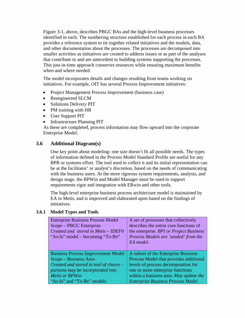
Figure 3-1, above, describes PBGC BAs and the high-level business processes identified in each. The numbering structure established for each process in each BA provides a reference system to tie together related initiatives and the models, data, and other documentation about the processes. The processes are decomposed into smaller activities as initiatives are created to address issues or as part of the analyses that contribute to and are antecedent to building systems supporting the processes. This just-in-time approach conserves resources while ensuring maximum benefits when and where needed.
The model incorporates details and changes resulting from teams working on initiatives. For example, OIT has several Process Improvement initiatives:
• Project Management Process Improvement (business case) • Reengineered SLCM • Solutions Delivery PIT • PM training with HR • User Support PIT • Infrastructure Planning PIT As these are completed, process information may flow upward into the corporate Enterprise Model.
3.6 Additional Diagram(s) One key point about modeling- one size doesn’t fit all possible needs. The types of information defined in the Process Model Standard Profile are useful for any BPR or systems effort. The tool used to collect it and its initial representation can be at the facilitator’ or analyst’s discretion, based on the needs of communicating with the business users. At the more rigorous system requirements, analysis, and design stage, the BPWin and Model Manager must be used to support requirements rigor and integration with ERwin and other tools.
The high-level enterprise business process architecture model is maintained by EA in Metis, and is improved and elaborated upon based on the findings of initiatives.
3.6.1 Model Types and Tools
Enterprise Business Process Model Scope – PBGC Enterprise Created and stored in Metis – IDEF0 “As-Is” model – becoming “To-Be”
A set of processes that collectively describes the entire core functions of the enterprise. BPI or Project Business Process Models are ‘seeded’ from the EA model.
Business Process Improvement Model Scope – Business Area Created and stored in tool of choice – portions may be incorporated into Metis or BPWin “As-Is” and “To-Be” models
A subset of the Enterprise Business Process Model that provides additional levels of process decomposition for one or more enterprise functions within a business area. May update the Enterprise Business Process Model

and/or ‘seed’ a Project Business Process Model.
Project Business Process Model Scope – Project Created and stored in BPWin and Model Manager – IDEF0 and IDEF3
A model that comprehensively describes the scope of business processes to be automated by an application. This model synchronizes with logical data model, enables CRUD matrix, reflects business requirements, and is reusable.
Table 3-2: Model Types and Tools
3.6.2 Integrated Definition (IDEF) Modeling IDEFØ: IDEFØ is a method designed to model the decisions, actions, and activities of an organization or system. According to the IDEF Web site:
…The United States Air Force commissioned the developers … to develop a function modeling method for analyzing and communicating the functional perspective of a system. Effective IDEFØ models help to organize the analysis of a system and to promote good communication between the analyst and the customer. IDEFØ is useful in establishing the scope of an analysis, especially for a functional analysis. As a communication tool, IDEFØ enhances domain expert involvement and consensus decision-making through simplified graphical devices. As an analysis tool, IDEFØ assists the modeler in identifying what functions are performed, what is needed to perform those functions, what the current system does right, and what the current system does wrong. Thus, IDEFØ models are often created as one of the first tasks of a system development effort. (Knowledge Based Systems, Inc. "IDEFØ Overview". 2000. Web site at: http://www.idef.com/idef0.html.)
In December 1993, the Computer Systems Laboratory of the National Institute of Standards and Technology (NIST) released IDEFØ as a standard for Function Modeling in FIPS Publication 183, Integration Definition for Function Modeling (IDEFO).
Figure 3-2: Example of Process from IDEF0. (From http://www.idef.com)
IDEF3: The IDEF3 Process Description Capture Method provides a mechanism for collecting and documenting processes. IDEF3 captures precedence and causality relations between situations and events in a form natural to domain

experts by providing a structured method for expressing knowledge about how a system, process, or organization works.
Figure 3-3: Example of Process from IDEF3. (From http://www.idef.com)
3.7 Business Process Domain FAQ A reference on IDEF and UML, is an article by Cheol-Han Kim et al, “The complementary use of IDEF and UML modeling approaches.”
Cheol-Han Kim, R.H. Weston, A. Hodgson, and Kyung-Huy Lee. "The complementary use of IDEF and UML modelling approaches" Computers in Industry 50:1 (January 2003). 35-56. Abstract available at http://portal.acm.org/citation.cfm?id=762062&dl=ACM&coll=portal.
The EA Process Team continues to look at advances in Business Process Management/Automation (BPM/BPA), and in standards such as BPMN and BPEL (Notation and Execution Language).
In version 1.0, no questions have been raised. When questions are raised in the future, they will be answered, and captured and exposed on the EA Blueprint portal.
3.8 Support The person assigned to maintain this section is Steve Finucane. You may ask questions or make suggestions concerning this section to him at x5185 or by e-mail at [email protected], or by contacting any Enterprise Architect. Also see the Process Section of the EA Blueprint.
This section was last updated on September 15, 2004.
3.9 Revisions
Version Date Description

1.0 July xx, 2004 Initial release version

4. Data Domain Section
4.1 Introduction The PBGC Enterprise Architecture is understood and described in several domains (see Introduction). This section describes the Data Domain target architecture. The data architecture describes a model by which all PBGC data assets are managed and stored from the initial acquisition of the data until it is archived to offline storage. Each phase in the life cycle of the data is described by using both a PDF diagram and text in this Word document. The different phases of the data are broken down into layers so that each phase can work with the data in the most efficient manner.
4.2 Benefits The benefits of separating the data into different layers allows for the data to be modeled and stored for each specific use (acquisition, transactional processing, and reporting and analysis.)
4.3 Organization The information in this section is captured in various formats, as appropriate to the type of information (i.e., PDF files, Excel spreadsheets, Word documents, PowerPoint slides, portlets, and URL references). The complete set of presentation elements can be reached at the portal site EA Blueprint Publication. (If you are reading this document on paper, some presentation elements may not be included; see footnote 1 in paragraph 11 below.)
The information in this section is organized and presented as follows:
Item Format Name/Description
1 Word Data Domain Section (this document): Text document describing the Application Domain Section of the PBGC EA Blueprint, including the PBGC target Service-Oriented Architecture (SOA) in a Java environment, and related processes and support. The section also includes descriptions of the other presentation elements listed below.
2 PDF Data Architecture Diagram 3 PDF Information Architecture Diagram.
4.4 Overview of PBGC Target Data Architecture The lifecycle of data within the PBGC data layer spans from the point of capture to the point that is it no longer useful and is archived. The hub of the data architecture is a corporate repository of data, consisting of one or more physical databases that store and manage clean, accurate and timely information for the use of common services and applications. Elements of the data architecture describe the full lifecycle of information within PBGC:

• Data acquisition—capture of data from external sources, including terminated pension plan data, IRS Form 5500 data, and Social Security Administration data, as well as low-volume data sources, such as EDGAR filings and financial ratings of corporations.
• Cleansing and Loading—application of data quality rules to incoming data to flag errors for correction or deletion; mapping of data interfaces to transform external data to standard PBGC data specifications; reformatting and loading; and the capability to detect load errors and restart a data load.
• Data Preparation—correction, validation, or reconciliation of data prior to entering the data repository, according to specific business logic or via user evaluation and/or authorization.
• Transaction Processing—the central element of the data layer repository—provides storage, update, management, and archiving of operational data for all business areas of PBGC.
• Data Transformation—calculations and sorting required to prepare data for use in data marts specific to the reporting requirements of a business area
• Reporting and Analytics—ad hoc, user-defined reporting and data analysis capabilities, the provision of direct user access to metadata via a web browser, and automated data impact analysis.
4.4.1 Data Acquisition When data is received from external sources, it is captured by COTS Extract, Transformation, and Load (ETL) software. Data in the original source formats is mapped to the target standard PBGC specifications, values, and formats.
Transition activities
• Develop a specification of the superset of pension plan and participant data required for PBGC plan trusteeship
• Document the specifications of existing standard external interfaces.
4.4.2 Cleansing and Loading Data ETL technology provides several key features to standardize and improve the quality and accuracy of the data layer. Implementing ETL eliminates the necessity of developing native code from scratch for every interface. The extract function reads data from a specified source and extracts a desired set or subset of data. The transformation function works with the acquired data, using data maps of formats and lengths and lookup tables, or creating combinations/concatenations with other data elements, to convert it to the desired state. The load function writes the resulting data (either the entire set or limited to data changes) to a target database. ETL can be configured to load the repository directly or can be used with one or more staging areas for additional preparation of high-volume data or data requiring user analysis prior to storage. Commercially available ETL software features robust backup, restart, and remote operation capabilities.
Another feature that is important for PBGC is the support of data quality checking during the transformation process—from mandatory data, formats, and values to applying detailed business rules—facilitating the desired degree of data quality
control for each record type. For example, it may be a requirement that a participant record from a newly trusteed pension plan must have a Social Security Number. If a record without this element is found, the ETL tool may be programmed to reject it or flag it with an error code.
Transition Activities
• Select, purchase, and deploy standard PBGC ETL software • Implement standard PBGC data formats and allowed values for
implementation in the enterprise data repository • Transfer specifications and data mappings, currently processed from regular
external sources via native code, to a PBGC standard ETL tool • Determine the level of data quality monitoring to be applied at the loading
stage of the data life cycle for each record type.
4.4.3 Data Preparation According to the specific business requirements of PBGC business areas, some data acquired from external sources may require additional preparation, validation, corrections, reconciliation with existing data, or user authorization before it is allowed to be loaded into the repository. These tasks can be accomplished through additional ETL programs or may be supported via one or more temporary staging area data stores.
Transition Activities
• Classify known data quality errors received through batch data loads • Determine the criteria for rejection, flagging, or assigning error codes to
incomplete, erroneous, or suspect records. • Determine which deficiencies can be corrected by additional business logic or
comparison with existing records in the Enterprise Data Repository versus those that require manual verification, authorization, or modification.
• Enhance the Enterprise Data Repository to accommodate information about the fact that a record was corrected, is of dubious value, etc.
• Determine legal retention requirements and if there is a need to retain incoming data exactly as it was received
• Determine the storage duration of records in the staging area.
4.4.4 Transaction Processing and Permanent Data Storage Online transaction processing takes place within the Enterprise Data Repository, consisting of one or more physical databases in which records are created, modified, deleted, and read. The data structures of the repository are relational and normalized to accommodate the efficient operation of components and provide flexibility to store data that is the product of different business requirements without conflicts, allow new values to be added without recreating the database, and so forth.
The Enterprise Data Repository is specified and designed via data models created in the PBGC standard data modeling tool. Both logical (business data

requirements) and physical (design specifications) models are produced and maintained. Data enters the repository via one of three paths: • Directly from the ETL cleansing and loading process • Through the staging database following additional data actions • By an application user through common service components • Timely, accurate, non-conflicting data is provided to applications and external applications via service components. There is no direct user access. The data is stored permanently, until such time as the PBGC determines that it is no longer useful, when it may be archived.
Transition Activities
• Design and implement the Enterprise Data Repository and staging database in phases, dependent upon business priorities and target application implementation dates
• Design and implement the common services that will act on the data in the repository and deliver it to applications
• Provide transition views of the repository data for legacy applications • Transition existing applications to the new database and to common services
as major redesign projects are initiated.
4.4.5 Data Transformation The data transformation layer provides the means by which atomic, transactional data is aggregated, summarized, sorted, and stored to prepare it for direct access by a user through ad hoc reporting software (also called ‘Business Intelligence’). A selected subset of the normalized data stored in the repository is transformed via business logic implemented in the ETL layer, re-structured in an optimized denormalized form (which is a ‘dimensional’ model or ‘cube’ structure) in a database oriented to a specific business area (or ‘data mart’) to optimize performance for reporting.
Aggregations are developed during transformation to support specific business requirements. For example, the ETL tool may derive a total count of the participants put in pay within a specified time period for a new plan, and the number of personnel directly involved with this task in the same time period, supporting a calculation of the number of staff resources required to put a participant into pay during a specific time period.
Transition Activities
• Determine priorities for and scope of data marts by business area • Analysis and specification of reporting requirements for each data mart • Requirements for analysis, specification, and implementation of data
selection, aggregation, calculation, and sorting requirements in the ETL layer • Modeling, design and implementation of the data marts.
4.4.6 Reporting and Analytics – Business Intelligence and Data Mining The reporting and analytics layer of the data architecture supports online ad hoc reporting (also known as ‘decision support’ or Business Intelligence (BI)) and data analytics (also known as ‘data mining’ or ‘knowledge discovery’), empowering end users to explore information from different perspectives to extract business value that will support better understanding of business processes and informed decisions.
BI tools contain a powerful feature set that supports user-designed reports, data visualization, scenario exploration, event alerts, and trend analysis, with the capability of drilling down to atomic transactions as required. Data mining software supports the process of finding correlations or patterns among multiple records and columns in large relational databases via complex operations and artificial intelligence, and developing profiles of data that lead to a conclusion, for example, that a company is a likely risk for plan termination. Data mining is a promising technology to support regulatory compliance and investigations.
Transition Activities
• Develop data marts to support the correct data subsets and transformations for business area requirements.
• Train end users on the standard PBGC BI software. • Determine priorities and objectives for knowledge discovery applications.
4.4.7 Data Dictionary: User Access to Metadata A metadata repository provides convenient end-user access to multiple sources of information about data and the relationship of data to applications, programs, and services. The primary metadata supplied via the repository comes from the logical and physical data models. The metadata for each element of the database includes definitions, values, lengths, formats, optionality, and location in the one or more tables in which it is used. Since each data object in a logical data model is uniquely named and defined, the metadata repository covers the data landscape of the organization, providing a ‘single version of the truth.’ Other sources of metadata acquired (or ‘scanned’) by the repository include the application code library, service components, production databases, and ad hoc sources like Access databases and spreadsheets.
A user can select from lists (by alphabetical order, by application, or by database) or search by name of an entity type, attribute, table, or column, and retrieve information about that data object and a list of the models, tables and code that uses the object. In addition, the metadata repository provides a very important feature for OIT; it simplifies and shortens the time required for impact analysis, enabling traceability for data objects involved in an impending modification to interfaces or application programs.
4.5 Information Architecture The information architecture diagram is simply a representation of the enterprise data model showing the each business area contains a combination of shared data

and nonshared data. The purpose of the diagram is to represent that a corporate wide view of the data must be taken in order to eliminate duplication and data quality errors. The areas shown on the diagram are for representation only and should not be considered to be comprehensive. The business area are broken down for budgeting purposes and do not necessarily represent a natural division of data.
4.6 Support The person assigned to maintain this section is John Kidd. You may ask questions or make suggestions concerning this section to him at x3681 or by e-mail at [email protected], or by contacting any Enterprise Architect. Also see the Process Section of the EA Blueprint.
This section was last updated on July 22, 2004.
Version Date Description
1.0 on July xx, 2004 Initial release version

Information ArchitecturePortalLink
4.4) Subject Areas: EnterpriseShared Data
Pension Plans Organizations ContactInteractions
Workflow &ApprovalsIndividuals
Legal Cases
4.3) Subject Areas: Operational Support (BA3)
4.2) Subject Areas: Plan Termination (BA2)4.1
) Sub
ject
Are
as: P
ensio
n In
sura
nce
(BA1
)
Staff Resources
Revolving FundInvestments
Procurements
PublicAffairs
Policies &Regulations
LegislationInformationTechnology
Budgeting
StrategicPlanning
Vendors
Financials
Facilities CommunicationsInvestigations& Audits
Spon
sors
Adm
inis
trato
rsTr
uste
esPr
emiu
mIn
sura
nce
Paym
ents
Plan
Ass
etsPl
anM
onito
ring
Stan
dard
Term
inat
ions
Repo
rtabl
eEv
ents
Prac
titio
ner
Nego
tiatio
ns&
Case
s
Actu
aria
lCa
lcul
atio
nsTrus
t Fun
dIn
vest
men
ts
Prac
titio
ner
Appe
als Paym
ents
Benefit
ValuationsBenefit
Appeals
Participants
Benficiaries
Other Payees
Benefit
Entitlements
Plan
Participation
Plan
Settlements
Benefit
Actuarial
Calculations
Distress
Terminations
Trusteeship
The Information Architecture diagram attempts to map the defined Common Services to the data subject areas for BA1 and BA2.�

Data ArchitecturePortalLink
17.2) Cleanse & Load
17.1) External Data Acquisition
17.5) Data Transformation
17.7) Reporting& Analytics
17.3) Data Preparation
Plan
Dat
a
IRS
5500
Soci
al S
ecur
ityA
dmin
istr
atio
n
Data QualityChecking
Extract, Transform & Load(ETL - COTS)
Interface DataMapping
BackupRestart &
Error Fixes
Corrections &Reconciliations
17.4) Transactional Processing -"Gold Source
NormalizedRelational
Com
mon
Ser
vice
s(C
ompo
nent
s ac
t on
data
)
App
licat
ions
Bus
ines
s R
ules
& U
ser
Inte
rfac
es
Real-TimeAccess
Exte
rnal
App
licat
ion
Serv
ice
(e.g
. Sta
te S
treet
Ban
k)
ETL: Combine,Calculate, Sort &
LoadDe-normalizedDimensional
COTS UserReporting
Tools
17.6) Data DictionaryMetadata
RepositoryWeb Access
Authorizations &Staging
Enterprise DataRepository
Data Marts(IOD, FOD, Future)
Data ModelMetadata
Specifies
DataMining

5. Applications Domain
5.1 Introduction The Application Domain of PBGC’s enterprise architecture is responsible for describing the tools and technical methods by which data is securely created, read, updated and modified. The PBGC To-Be application architecture is designed to be an example of service oriented architecture (SOA). SOAs use a modular approach in which each composite or virtual application is composed of a number of different discrete services. Services can be derived from existing applications or by exposing key functionality as services, as well as from new service-oriented applications. A SOA is simply a method by which an application’s smaller functions (for example, security, address changes, or letter generation) are developed to be reusable. These reusable functions can then be recombined to build large complex applications without having to rewrite the code. In order for this to be possible PBGC must adopt standards for development of these services or functions.
The Application Domain is represented by multiple diagrams that are identified and described below.
5.2 Benefits With the modularity of SOA, individual services can even be removed or replaced wholesale without adversely affecting the overall composite application. Developers do not need to reinvent code each time they are called upon to integrate a new application. New functionality can be achieved without modifying existing applications. Generalized “common services” will replace hard-coded integrations, freeing the developer to concentrate on the overall solution and meeting the business requirements. System wide enhancements can be made in just one place and all applications that use that feature will automatically have the enhancement without any additional coding.
5.3 Organization The information in this section is captured in various formats, as appropriate to the type of information (i.e., PDF files, Excel spreadsheets, Word documents, PowerPoint slides, portlets, and URL references).
The complete set of presentation elements can be reached at the portal site EA Blueprint Publication.
(If you are reading this document on paper, some presentation elements may not be included; see footnote 1 in paragraph 11 below.)
The information in this section is organized and presented as follows:
Item Format Name/Description 1 Word Application Domain Section (this document). Text document
describing the Application Domain Section of the PBGC EA
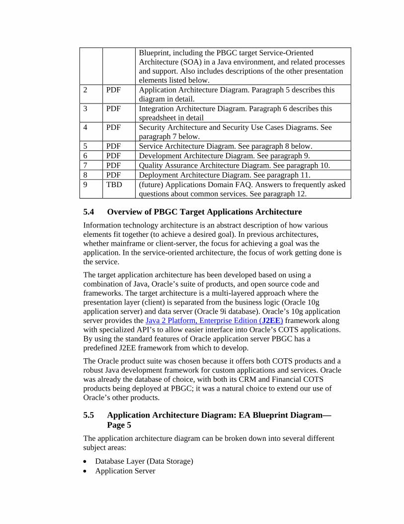
Blueprint, including the PBGC target Service-Oriented Architecture (SOA) in a Java environment, and related processes and support. Also includes descriptions of the other presentation elements listed below.
2 PDF Application Architecture Diagram. Paragraph 5 describes this diagram in detail.
3 PDF Integration Architecture Diagram. Paragraph 6 describes this spreadsheet in detail
4 PDF Security Architecture and Security Use Cases Diagrams. See paragraph 7 below.
5 PDF Service Architecture Diagram. See paragraph 8 below. 6 PDF Development Architecture Diagram. See paragraph 9. 7 PDF Quality Assurance Architecture Diagram. See paragraph 10. 8 PDF Deployment Architecture Diagram. See paragraph 11. 9 TBD (future) Applications Domain FAQ. Answers to frequently asked
questions about common services. See paragraph 12.
5.4 Overview of PBGC Target Applications Architecture Information technology architecture is an abstract description of how various elements fit together (to achieve a desired goal). In previous architectures, whether mainframe or client-server, the focus for achieving a goal was the application. In the service-oriented architecture, the focus of work getting done is the service.
The target application architecture has been developed based on using a combination of Java, Oracle’s suite of products, and open source code and frameworks. The target architecture is a multi-layered approach where the presentation layer (client) is separated from the business logic (Oracle 10g application server) and data server (Oracle 9i database). Oracle’s 10g application server provides the Java 2 Platform, Enterprise Edition (J2EE) framework along with specialized API’s to allow easier interface into Oracle’s COTS applications. By using the standard features of Oracle application server PBGC has a predefined J2EE framework from which to develop.
The Oracle product suite was chosen because it offers both COTS products and a robust Java development framework for custom applications and services. Oracle was already the database of choice, with both its CRM and Financial COTS products being deployed at PBGC; it was a natural choice to extend our use of Oracle’s other products.
5.5 Application Architecture Diagram: EA Blueprint Diagram—Page 5
The application architecture diagram can be broken down into several different subject areas:
• Database Layer (Data Storage) • Application Server

• Web Server
5.5.1 The Database Layer The Database layer uses version 9.2.0.5 of the Oracle 9i database, which manages the message queuing, scheduling of jobs, and storage of data.
• Queuing—Advanced Queuing and message queuing operations can be performed in a manner similar to Structured Query Language (SQL) operations from the Oracle database. Message queuing functionality allows applications on Oracle database to communicate asynchronously via messages in AQ queues. Integration with the database brings the unprecedented levels of functionality, operational simplicity, reliability, and security to message queuing. It offers unique message management functionality—such as auditing and tracking—to the message queuing world.
• Job Scheduling—the Oracle job queue allows for the scheduling and execution of PL/SQL routines (jobs) at predefined times and/or repeated job execution at regular intervals.
5.5.2 The Application Server The Application server is hosted on the Oracle 10gAS application server (version 9.0.4). The Oracle application server supports the use of the J2EE framework along with Oracle’s extensions. The application server supports web services, business logic, messaging, job scheduling, component interaction, and security management.
• Java Connector Architecture—The J2EE Connector architecture defines a standard architecture for connecting the J2EE platform to heterogeneous Enterprise Information Systems (EIS). Examples of EIS include ERP, mainframe transaction processing, database systems, and legacy applications not written in the Java programming language. By defining a set of scalable, secure, and transactional mechanisms, the J2EE Connector architecture enables the integration of EISs with application servers and enterprise applications.
• Persistence Layer—Oracle Toplink provides a highly flexible and productive mechanism for storing Java objects and Enterprise Java Beans (EJBs) in relational database tables.
• Domain Objects—POJO (Plain Old Java Object) denotes a normal Java object that is not a Java Bean, an Entity Bean, a Session Bean, etc., and does not serve any other special role or implement any special interfaces of any of the Java frameworks.
• Job Scheduling—Quartz is an open source job scheduling system that can be integrated with, or used along side virtually any J2EE or Java 2 Platform, Standard Edition (J2SE) application. Quartz can be used to create simple or complex schedules for executing tens, hundreds, or even tens-of-thousands of jobs; jobs whose tasks are defined as standard Java components or EJBs.

• Web Services—JAX-RPC provides an easy to develop programming model for development of SOAP based Web services. You can use the RPC programming model to develop Web service clients and endpoints.
• Message Queuing—The Java Message Service (JMS) API is a messaging standard that allows application components based on the Java 2 Platform, Enterprise Edition (J2EE) to create, send, receive, and read messages. It enables distributed communication that is loosely coupled, reliable, and asynchronous.
• EJB 2.0—Enterprise JavaBeans (EJB) technology is the server-side component architecture for the Java 2 Platform, Enterprise Edition (J2EE) platform. EJB technology enables rapid and simplified development of distributed, transactional, secure and portable applications based on Java technology. • Entity Beans—an entity bean represents a business object in a persistent
storage mechanism. Some examples of business objects are customers, orders, and products. In the J2EE SDK, the persistent storage mechanism is a relational database. Typically, each entity bean has an underlying table in a relational database, and each instance of the bean corresponds to a row in that table.
• Session Beans—a session bean represents a single client inside the J2EE server. To access an application that is deployed on the server, the client invokes the session bean's methods. The session bean performs work for its client, shielding the client from complexity by executing business tasks inside the server. As its name suggests, a session bean is similar to an interactive session. A session bean is not shared--it may have just one client, in the same way that an interactive session may have just one user. Like an interactive session, a session bean is not persistent. (That is, its data is not saved to a database.) When the client terminates, its session bean terminates and is no longer associated with the client.
• Stateful Session Beans—the state of an object consists of the values of its instance variables. In a stateful session bean, the instance variables represent the state of a unique client-bean session. Because the client interacts ("talks") with its bean, this state is often called the conversational state. The state is retained for the duration of the client-bean session. If the client removes the bean or terminates, the session ends and the state disappears. This transient nature of the state is not a problem, however, because when the conversation between the client and the bean ends there is no need to retain the state.
• Stateless Session Beans—a stateless session bean does not maintain a conversational state for a particular client. When a client invokes the method of a stateless bean, the bean's instance variables may contain a state, but only for the duration of the invocation. When the method is finished, the state is no longer retained. Except during method invocation, all instances of a stateless bean are equivalent, allowing the EJB container to assign an instance to any client.

5.5.3 The Web Server The Web Server is also hosted on the Oracle application server and provides support for managing the user interface, session and identity management, along with the processing of XML documents, and security for the user. The Apache Jakarta open source framework Struts is also loaded to support a Model, View, Controller (MVC) approach for separating the user interface from the business logic and data.
• Persistence Layer—Oracle Toplink provides a highly flexible and productive mechanism for storing Java objects and Enterprise Java Beans (EJBs) in relational database tables.
• XML Processing—The Java API for XML Processing (JAXP) enables applications to parse and transform XML documents independent of a particular XML processing implementation.
• Domain Objects—POJO (Plain Old Java Object) denotes a normal Java object that is not a Java Bean, an Entity Bean, a Session Bean, etc., and does not serve any other special role or implement any special interfaces of any of the Java frameworks.
• Struts, an MVC2 implementation—Struts is a set of cooperating classes, servlets, and JSP tags that make up a reusable MVC 2 design. This definition implies that Struts is a framework, rather than a library, but Struts also contains an extensive tag library and utility classes that work independently of the framework.
5.5.3 Struts overview
• Client browser—An HTTP request from the client browser creates an event. The Web container will respond with an HTTP response.
• Controller—The Controller receives the request from the browser, and makes the decision where to send the request. With Struts, the Controller is a command design pattern implemented as a servlet. The struts-config.xml file configures the Controller.
• Business logic—the business logic updates the state of the model and helps control the flow of the application. With Struts this is done with an Action class as a thin wrapper to the actual business logic.
• Model state—the model represents the state of the application. The business objects update the application state. ActionForm bean represents the Model state at a session or request level, and not at a persistent level. The JSP file reads information from the ActionForm bean using JSP tags.
• View—the view is simply a JSP file. There is no flow logic, no business logic, and no model information -- just tags. Tags are one of the things that make Struts unique compared to other frameworks like Velocity.
• HTTP Session—provides a way to identify a user across more than one page request or visit to a Web site and to store information about that user. The Application server servlet container uses this interface to create a session between an HTTP client and an HTTP server. The session persists for a specified time period, across more than one connection or page request from

5.5) Operating System: Mid Tier - Linux | Data Tier - Solaris
5.4) Logging: log4j
5.3) Persistence Container: Oracle RDBMS
5.1) Web Server: Oracle 10gAS (9.0.4)
SecurityManagement
ServiceManagement
PersistanceManagement
JobManagement
SecurityManagement
DatabaseManagement
JobManagement
ApplicationManagement
PersistanceManagement
Oracle 9i 9.2.0.5
SessionManagement
User InterfaceManagement
Job Scheduling
SecurityManagement
Message Queuing:AQ
ComponentInteraction
Application Architecture
Dependency Injection: picoContainer
JDBC
5.2) Application Server: Oracle 10gAS (9.0.4)
Http Session / Security Filter
MVC: Struts 1.2.2UI Framework:
JSP 1.2
PortalLink
5.6)
Com
pone
nt M
anag
emen
t: JM
X 1.
2
5.7)
Net
wor
k M
anag
emen
t: SN
MP
Workflow / Rules Engine: ?
Legacy Integration: JCA 1.0
JobScheduling:
Quartz
Web ServicesProtocolStack:
JAX-RPC 1.1
MessageQueuing:
OJMSImpl, JMS
1.1
Persistence Layer:Container Managed - TopLink,
Bean Managed
Domain Objects: POJO
EJB 2.0
Stateless SessionBeans &
Message Beans
Entity Beans
StatefulSessionBeans
Persistence Layer:TopLink
XML Processing:JAXP 1.1
Domain Objects: POJO
XML/
SOAP RM
I
JDBC
RM
I
This diagram illustrates the internal components and products that may be used within, and in support of, and application. When developing an application software architecture, many small decisions are required. However, the sum of these small decisions when spread across the enterprise can add up to significant differences between application architectures. These multiple solutions increase the overall maintenance costs and dilute the organizations capability to develop reusable levels of expertise.�

the user. A session usually corresponds to one user, who may visit a site many times. The server can maintain a session in many ways such as using cookies or rewriting URLs.
• Component Management—Java Management Extensions (JMX) is a reusable framework for exposing your application to remote or local management tools. JMX enables you to query the configuration settings and change them during runtime. It also provides other services, such as monitoring, event notification, a timer, and dynamic class loading from XML files. You can use JMX to load, initialize, change, and monitor your application and its distributed components.
5.6 Integration Architecture Diagram: EA Blueprint Diagram—Page 6
The integration architecture diagram shows the various methods and standards used to communicate with legacy applications, web clients, and the database. The diagram shows how the Java Connector Architecture (JCA resource adapters 2.2) is used to communicate with external or encapsulated systems and that these systems are not directly connected to the database. The diagram also shows how the JCA adapters work with the servlet and EJB session beans to connect to the database using the Java Data Base Connector (JDBC) or the Oracle Java Messaging Service (OJMS). Another method shown in the diagram is how the Simple Object Access Protocol (SOAP 1.1) service interface can interact with either the servlet container or the EJB container to access the data. The SOAP service would be primarily used by a web service connector to access a service.
5.7 Security Architecture: EA Blueprint Diagram—Page 8 These diagrams show the security components of application security for PBGC’s SOA in the Java environment and security use cases. The security architecture diagram can be broken down into several different method of access, internal or “Intranet” and external or “Internet” access in combination with authentication (identity), and authorization (RBAC—role based access control). Finally Oracle’s virtual private database feature is used to control row level access to data. This multilayer approach while complex provides a robust model for protecting PBGC’s data assets.
5.7.1 Internet—External Access Accessing the PBGC application security through the internet will provide multiple layers of security. The first layer of security will be the firewall which will control access to the server and its services. Remote access through the firewall using Tarantella will allow the use to be identified to the internal network. From there their identity will be authenticated by Microsoft’s Active Directory service just like an internal user.
5.7.2 Intranet—Internal user access The internal user will be required to login to the network so that their identity can be verified by the Active Directory service. Once they have been authenticated

6.4) EncapsulatedSystems: Not
integrated at thedatabase level
6.3) ResourceAdapters: JCA
6.1) Service Interface: SOAP 1.1
6.2) Messaging: JMS
WorkflowEngine
Sync
hron
ous
Req
uest
s
Sync
hron
ous
Req
uest
s
Sync
hron
ous
Req
uest
s
Integration Architecture
Oracle Database
Message Consumer
Asynchronous MessageBus
(JMS Provider: OJMS)
EJBMessage
Bean
JDB
C
Alternate Implementation Choice
JDB
C
PL/SQL Stored Procedures
AD
O.N
ET
JDB
C
JCA Adapters included in OracleAS EElicense (ProcessConnect):FTP AdapterSMTP AdapterHTTP AdapterAQ AdapterOracle DB AdapterJMS AdapterWeb Services Adapter
SMTPConnector
SMTP ServerIMAP Server
HTTPConnector
HTTP ServerHTTP Client
FTPConnector
FTP ServerFTP ClientFilesystem
Web ServicesConnector
WS ServerWS Client
Image ServiceResourceAdapter(ISRA)
Filenet
LegacyConnector
LegacySystem
Image ServiceResourceAdapter(ISRA)
ISRA not currently supportedon Oracle Application Server
ASP.NETWeb
Service
ServletContainer:
POJO
EJB Container:Stateless Session
Bean
PortalLink
Integration Architecture presents a high level view of the technologies that should be leveraged when integrating multiple applications, or responding to external business events (file upload, web service call from a business partner, ...)�

they will not need to login again because the Oracle 9ias service will use an authentication filter (Wedgetail) to provide the Java application their identity. This identity will be used to determine their role which will return all of the functions that a user has access to use. These functions will be shown as menu items to the user in their browser interface.
5.7.3 Role Based Access Control—RBAC The goal of role based access is to only have to define the business roles of an organization and not to assign access to each staff member individually. This way when new staff is hired they can quickly be provided application and database access based on upon the role they perform.
• Virtual Private Database—the use of the Oracle database management system allows the roles to be further extended into creating a virtual database. A virtual database uses the existing database and applies a set of filters to it to create a virtual copy. In doing this if a user only has access to a single plan the database would appear to only contain that plan. This provides tight control over the data without having to write code into each application that retrieves the data.
5.8 Service Architecture (Message Security) Diagram: This diagram is found on page 9 of the EA Blueprint Diagram.
Message level security provides end-to-end verification of message integrity, non-repudiation, and optionally provides confidentiality. Legacy web technologies, such as Secure Socket Layer (SSL), are not appropriate for messaging applications since each message may take multiple paths, have multiple hops on each path (each having its own processing), and have multiple destinations.
Two methods of encrypting and managing credentials are readily adaptable to the PBGC environment: Kerberos, and a Public Key Infrastructure (PKI—X.509 Certificates). Kerberos has been selected as the technology of application authentication of users, and PKI for application to service messaging and end-to-end secure messaging from external sources.
It is important to understand that not all services will require secure messaging. Each deployed service must have a risk analysis and understand the trust boundaries of the deployment environment in order to determine the appropriate level of security required.
8.1 Block 9.1 of the EA Blueprint Diagram illustrates the components involved in passing a message from an application to a service.
8.1.1 Beginning at the left of the diagram, the Browser will interact with the application through the Wedgetail authentication component. The Wedgetail component will require a Kerberos ticket which the Browser will obtain from Active Directory.
8.1.2 A component placed in front of the application will inject the Users credentials into a JAAS (Java Authentication and Authorization Service) Subject and initiate the user session.
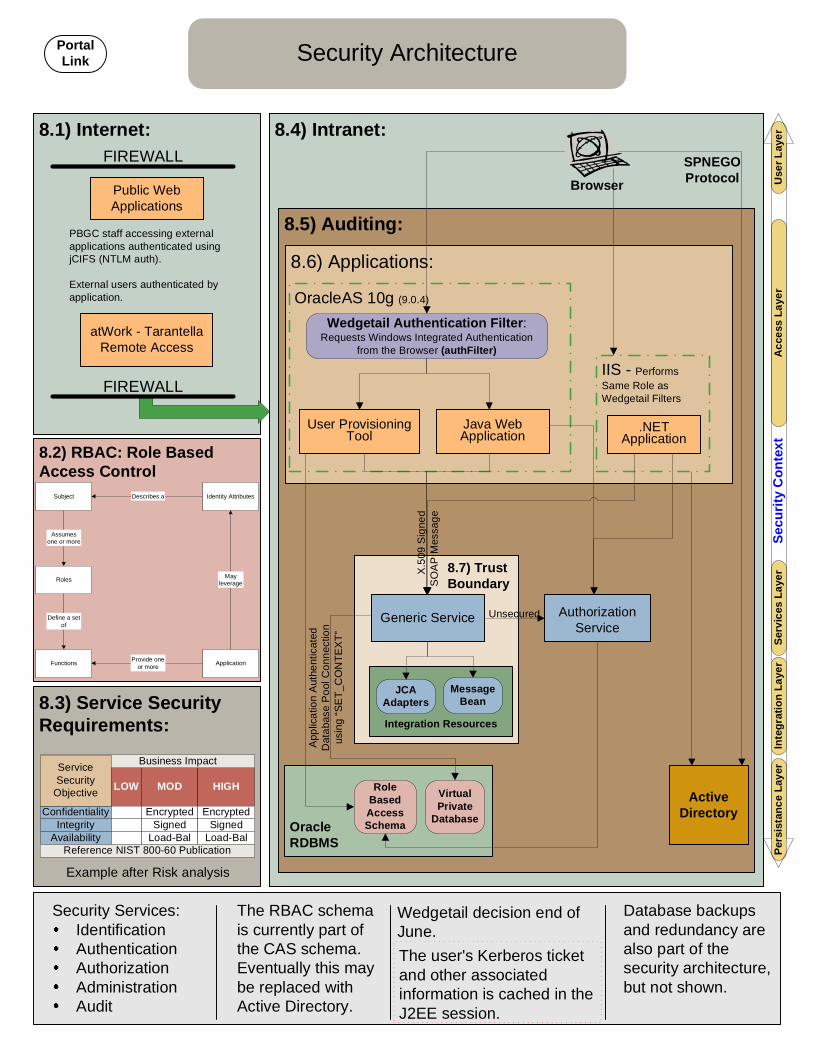
8.4) Intranet:
8.5) Auditing:
8.7) TrustBoundary:
8.6) Applications:
8.3) Service SecurityRequirements:
8.2) RBAC: Role BasedAccess Control
8.1) Internet:
Security Architecture
OracleRDBMS
User ProvisioningTool
Wedgetail Authentication Filter:Requests Windows Integrated Authentication
from the Browser (authFilter)
SPNEGOProtocol
RoleBasedAccessSchema
AuthorizationService
.NETApplication
Security Services:IdentificationAuthenticationAuthorizationAdministrationAudit
Subject
Roles
Functions Application
Identity Attributes
Assumesone or more
Define a setof
Provide oneor more
Describes a
Mayleverage
FIREWALL
FIREWALL
Public WebApplications
atWork - TarantellaRemote Access
IIS - PerformsSame Role asWedgetail Filters
OracleAS 10g (9.0.4)
ActiveDirectory
The RBAC schemais currently part ofthe CAS schema.Eventually this maybe replaced withActive Directory.
VirtualPrivate
Database
Wedgetail decision end ofJune.
PBGC staff accessing externalapplications authenticated usingjCIFS (NTLM auth).
External users authenticated byapplication.
Database backupsand redundancy arealso part of thesecurity architecture,but not shown.
X.50
9 Si
gned
SOAP
Mes
sage
Unsecured
Appl
icat
ion
Auth
entic
ated
Dat
abas
e Po
ol C
onne
ctio
nus
ing
“SET
_CO
NTE
XT”
Browser
The user's Kerberos ticketand other associatedinformation is cached in theJ2EE session.
Integration Resources
MessageBean
Use
r Lay
erA
cces
s La
yer
Serv
ices
Lay
erPe
rsis
tanc
e La
yer
Secu
rity
Con
text
JCAAdapters
Inte
grat
ion
Laye
r
Generic Service
Java WebApplication
ServiceSecurity
ObjectiveLOW MOD HIGH
Confidentiality Encrypted EncryptedIntegrity Signed Signed
Availability Load-Bal Load-Bal
Business Impact
Reference NIST 800-60 Publication
PortalLink
ServiceSecurity
Objective
Example after Risk analysis

9.6) End-to-End Messaging Evaluation:
9.5) Asynchronous Messages:
9.4) Policy:
9.3) Sequence Diagram:
9.2) JAAS Subject:
9.1) End-to-End Message Security:Application Sandbox Common Service Sandbox
Service Architecture(Message Security)
Services have the following attributes:They maintain their own independent view of theirown data.They have their own identity, they do notimpersonate other users, but they know theidentity of the calling application and user.They maintain their own lifecycle.
Message Level Security provides end-to-endmessage verification.
Applications should be unaware ofmessage level security.
JAX-RPCWedgetail
Authentication JAX-RPC
WS-
Secu
rity
Han
dler
JAAS
Secu
rity
Polic
yH
andl
er
Auth
oriz
atio
nH
andl
er
Secu
red
Serv
ice
Appl
icat
ion
Popu
late
Subj
ect
WS-SecurityHandler
WS-
Secu
rity
Han
dler
Set
Invo
catio
nSu
bjec
t
Kerb
eros
Filte
r
Bro
wse
r
JAAS
Popu
late
Subj
ect
Activ
eD
irect
ory
SPN
EGO
Authorization Service
JAAS
Inje
ctio
nFi
lter
SecuredService
MessageBean
Message Queue(protected by queue
userid/password)JMS
Message
PrincipalsKerberosPrincipal
Public CredentialsPrivate CredentialsKerberosTicket
JAAS
JAAS Injection Filter createsthe JAAS Subject andpopulates it with the KerberosPrincipal and Kerberos TicketCredentials.
JAASInjection
Filter
KeyStore
SecureMessageHandler
KeyStore
AuthenticatedApplication
Message Queue
Non Secure Service
Sign
ed S
OAP
Mes
sage
Sign
ed S
OAP
Mes
sage
KeyStore
JAAS
Dire
ct Q
ueue
Acce
ss
Criteria Kerberos PKIInitial Implementation x xOngoing Maintenance x
External Access xInfrastructure Impact x
End-to-End Messaging xScalability x
TrustBoundaries
Service Invocation SecurityToken
MessageIntegrity
MessageAge
Un-secured - AnyClient None None 1 day
Internal TrustedApplication Client
X.509 CertificateRequired Signed 5 minutes
Web Services Policy Assertions
External ApplicationClient
X.509 CertificateRequired Signed 10 minutes
TransportEncryption
None
None
SSL
Browser ActiveDirectory Appl
Appl. MsgHandlers
Svc. MsgHandlers
SecuredService
RequestResourceRequire
AuthenticationKey
NegotiationKerberos
Ticket RequestResource (with Ticket)
ServiceRequest Signed
Message VerifiedMessageServiceResultsSigned
MessageVerifiedMessageRequest
Results
JAAS
Polic
y
JAAS
Polic
y
Expected performance penalty for one-waysigning of messages is 50%.
Security handlers and keystores are necessary forsecured services only.
Sour
ceID
Inje
ctio
nH
andl
er
Sour
ceID
Inje
ctio
nH
andl
er
PortalLink

8.1.3 The Application will use the JAAS subject and access the Authorization Service to validate the user privileges. Access to the Authorization Service is not a secure request.
8.1.4 When the Application does make a request to a secured service, the SOAP message will pass through JAX-RPC message handlers. These message handlers can be designated at deployment, thus keeping the actual application unaware of message level security being used. The handlers will: inject source information (e.g. application identity, server IP address) into the message; apply WS-Security signatures and encryption; decrypt and verify messages; apply security policy information; and verify authorization.
8.2. Block 9.2 lists the sections of a JAAS Subject which include Principals, Private Credentials, and Public Credentials.
8.3. Block 9.3 illustrates the End-to-End Message Security using a sequence diagram and follows a generic message from the login of a user on a Browser, through the service request, message signature, message verification and the message return path.
8.4. Block 9.4 displays the types of Service Invocations where security may be required, and which types of security should be employed. These policy assertions would be enforced at application deployment.
8.5. Block 9.5 attempts to clarify how and when a secured message would be used in an Asynchronous messaging environment. The diagram displays two different trust boundaries that each includes the destination queue and message bean. Within these boundaries, the message does not need to be signed or encrypted. However, if an application used an unsecured service, that message would have to be signed by the application indicating the source of the message.
8.6. Block 9.6 simply shows where each of the security technologies excels according to different criteria. Where Kerberos may have easier ongoing maintenance costs, PKI is more accessible to external access, and scales easier than Kerberos.
5.9 Development Architecture Diagram: EA Blueprint Diagram—Page 10
The tools and API’s selected for developing services and applications are illustrated in this blueprint diagram.
9.1 Block 10.1 lists the products to use during the Requirements, Design and Analysis of an application. For requirements, Requisite Pro is selected. For Design and Analysis the All Fusion suite will be used consisting of: BPWin for process modeling, ERWin for Logical and Physical Data Models, and Component Modeler for all UML models.
9.2 Block 10.2 lists the implementation tools and Application Programming Interfaces (API) that components should support:
9.2.1 Integrated Development Environment (IDE): Oracle’s JDeveloper 9.0.4 is the primary development tool.

Ant 1.6.1 is the build tool. XDoclet 1.2 is for code generation. JUnit 3.8.1 for unit testing.
9.2.2 Server Container Oracle Application Server 10gAS version 9.0.4 supplies the EJB and servlet container OC4J 9.0.4. The Servlet API supported is version 2.3 Enterprise Java Beans (EJB) will be written to the 2.0 API. The Java Messaging Service (JMS) API version 1.1 is supported. The Java Management Extension (JMX) version 1.0 is supported.
9.2.3 Web Services—The following tools and APIs should be used in the development of Web Services. The JAX-RPC 1.1 API should be used when deploying web services, and SOAP message handlers. The JAX-RPC API is not integrated into the Oracle 10gAS 9.0.4 release. The Oracle specific API may be used until the migration to the 10.0.3 or later release. The JAXP 1.1 API should be used for manipulating XML data, the Xerces2 parser implementation of the JAXP API is the default parser. SOAP 1.1 is the standard SOAP version to use. If an XML editor is needed for development the XMLSPY 4.0 is the selected tool.
9.2.4 User Interface—The following tools and APIs should be used in the development of User Interfaces: Apache Struts 2.0 is the preferred implementation of the Model View Controller design pattern. Java Server Pages (JSP) version 1.2 is the preferred HTML templating tools Java Standard Tag Library (JSTL) 1.0 should be used.
9.2.5 Persistence—The following tools and APIs should be used in the development of object persistence. Oracle Toplink toolset should be used for Object to Relational mapping. Direct database interaction should be accomplished through the JDBC 2.0 API. The Oracle JDBC Driver 10.1.0 is the default JDBC driver. Oracle RDBMS 9.2.0.5 is the default database engine for new applications.
9.3 Block 10.3 lists the portal communities available to support development activities. These communities include: OIT Infrastructure—Engineering, Operations and Administration Enterprise Architecture IV&V Individual development projects may establish their own Portal Communities.
9.4 Block 10.4 illustrates the PVCS Repositories in use for promoting component reuse and the process for promoting components into the reuse repository.

5.10 Quality Assurance Architecture This section describes the Quality Assurance Architecture in the Applications Domain target architecture as found on page 11 of the EA Blueprint Diagram.
5.10.1 Benefits Quality Assurance Architecture has numerous benefits, including:
• System as developed meets business needs and requirements • System works as expected in target technical environment(s) • System smoothly interoperates with other IT services like Exchange, eALG,
and IPS • System consumes/provides services • System has acceptable performance (see EA Standards for System Response
Times) , does not degrade under load, and can scale to expected workload • System is maintainable
5.10.2 Quality Assurance Architecture Diagram This diagram provides a view of the quality assurance processes and tools applied to SOA-based Java and .Net development in PBGC. These principles also apply to other development efforts.
5.10.3 Quality Assurance Architecture Discussion Product Quality is usually defined along the line of whether the deliverable is defect-free and conforms to business functional requirement. Product quality reflects both the completeness of software or system features and functions, and error-free operation.
The road to high quality deliverables has dimensions affecting the user and the development community, and both must be jointly optimized so that business and performance needs are met.
Metrics for the developer include maintainability, interoperability, expandability, flexibility, reusability and portability. Metrics for the user include functionality, efficiency, reliability, security, usability, and verifiability.
Component quality is evaluated along several criteria: traceability, consistency, completeness and abstractness. For example, traceability refers to the ability to track a requirement from capture to design to code to test through implementation. Abstractness means that the component is as isolated as possible from details of specific application implementations in order to maintain flexibility, reusability, and portability.
As an example of abstractness, a common security service should be designed to provide an authentication mechanism that can be used by custom and COTS software. The design would meet the functional requirements of both, but each would have to adapt the service to meet the implementation specifics of their

11.1) QA Tools:
11.5) SLCM Testing Methodology: 11.4) User Quality Factors forComponents:
11.3) Component Quality Criteria:
Quality Assurance Architecture
Unit tests are required for allreusable components andservices. Unit test suitesmust be tied to thecomponents interfacespecification.
Development PlatformUnit Test
Functional Test
System Test
LimitedIntegration Test
ITC PlatformDeployment
System Test
Integration Test
IV&V Test
Certification &Accreditation
Test
User AcceptanceTest
TraceabilityConsistency
CompletenessAbstractness
ModularityStandards Compliance
CohesionSelf-Descriptiveness
FunctionalityEfficiencyReliabilitySecurityUsability
Verifiability
11.2) Developer Quality Factors forComponents:
MaintainabilityInteroperabilityExpandability
FlexibilityReusabilityPortability
UnitAgitar
Junit/NunitSOAPTest
ProfilingCompuWare: DevPartner
PerformanceLoadRunnerCompuWareSOAPTest
FunctionalWinRunner
DefectManagement
PVCS Tracker
RequirementsManagementRequisite Pro
PortalLink

application. The common service would be kept abstract, rather than being designed to provide customized methods for each new application.
SD Process Quality verification and validation to established policies, standards, procedures and guidelines for software development is outside the scope of this document. Please refer to the SLCM and IVV/PIT team protocols for specific guidance on applicable tests, sequencing, artifacts, processes and platform. Testing and QA will generally be a continuous effort, especially as we adapt iterative development processes.
Unit tests are required for all reusable components and services. Unit test suites must be tied to the components interface specification.
Requirements, both those that are new and those arising from defects, form the basis for tests. The repository for Requirements Management is Rational’s RequisitePro. The repository for Defect Management is Serena’s Merant Tracker.
5.10.3.1 Functional Testing Functional testing is accomplished with Mercury’s WinRunner. WinRunner captures, verifies, and replays user interactions automatically, so you can identify defects and ensure that business processes work flawlessly upon deployment and remain reliable.
Advantages include:
• Reduced testing time by automating repetitive tasks • Optimized testing efforts by covering diverse environments with a single
testing tool • Maximized return on investment through modifying and reusing test scripts as
the application evolves Source: http://www.mercury.com/us/products/quality-center/functional-testing/winrunner/ 5.10.3.2 Unit Testing Unit testing is done with two related products:
• JUnit—Testing is not closely integrated with development. This prevents you from measuring the progress of development- you can't tell when something starts working or when something stops working. Using JUnit you can cheaply and incrementally build a test suite that will help you measure your progress, spot unintended side effects, and focus your development efforts.
Extracted from http://junit.sourceforge.net/doc/testinfected/testing.htm#TestingPractices Also see http://www.junit.org/index.htm and ]http://junit.sourceforge.net/doc/cookbook/cookbook.htm
• NUnit—S unit-testing framework for all .Net languages. Initially ported from JUnit …NUnit brings xUnit to all .NET languages.
From http://www.nunit.org/index.html

5.10.3.3 Performance Testing Performance testing is done with Mercury’s LoadRunner. LoadRunner emulates hundreds or thousands of concurrent users and allows end-to-end and measurement of the response times. LoadRunner collects system and component-level performance. These allow identification of bottlenecks within the architecture.
LoadRunner is certified to work with ERP/CRM applications from Oracle and others. Capabilities include:
• Obtain an accurate picture of end-to-end system performance. • Verify that new or upgraded applications meet specified performance
requirements. • Identify and eliminate performance bottlenecks during the development
lifecycle. (Source: http://www.mercury.com/us/products/performance-center/loadrunner/ )
5.11 Applications Domain FAQ In version 1.0, no questions have been raised. When questions are raised in the future, they will be answered, and captured and exposed on the EA Blueprint portal.
5.12 Support The person assigned to maintain section 5.10, Quality Assurance is Steve Finucane. You may ask questions or make suggestions concerning this section to him at x5185, by e-mail, or by contacting any Enterprise Architect. Also see the Process Section of the EA Blueprint.
The person assigned to maintain this section is John Kidd. You may ask questions or make suggestions concerning this section to him at x6606 or by e-mail at [email protected], or by contacting any Enterprise Architect. Also see the Process Section of the EA Blueprint. This section was last updated on July xx, 2004.
Note that EA responsibility extends to providing a framework for standards and guidelines for SOA.
The SDM and PMO area provide for project management responsibility for development work. The IV&V and ITC areas provide the Quality assurance role. IE and IA areas provide for the deployment responsibilities of the applications and infrastructure. See the SLCM and the PIT processes.
This section was last updated on September 15, 2004.
Version Date Description
1.0 on July xx, 2004 Initial release version


10.4) PVCS Repositories:
10.3) Portal Communities:
10.2) Implementation:
10.1) Requirements, Design & Analysis:
Development Architecture
UserInterface
JSP 1.2JSTL 1.0
Struts 1.2.2
IDE
Ant1.6.1
XDoclet 1.2
Juni
t3.
8.1
JDev
9.0.4.0
JAX-RPC1.1 API
The JAX-RPC API is notintegrated into the Oracle10gAS 9.0.4 release. TheOracle specific API may beused until the migration tothe 10.0.3 or later release. JMX 1.0
JMX is not fullysupported in theOracle 9.0.4Application Server.
ProjectRepositories
EA ReuseRepository
EnterpriseArchitecture
OITInfrastructure
EngineeringOperationsAdministration
IV&V
DevelopmentProjects
Persistence
OracleJDBC
Driver 10.1.0
Ora
cle
RD
BMS
9.2.
0.5
Toplink
JDBC
2.0
API
WebServices
JAXP1.1 API
Xerces2 Impl
SOAP
1.1
XMLS
PY 4
.0JAX-R
PC
1.1 API
ServerContainer
ServletAPI 2.3
EJB
2.0
JMS
1.1
JMX
1.0O
racle
OC
4J 9.0.4
Requisite ProAll Fusion
BPWinERWinComponent Modeler
Final -Check into
EARepository
Promoted byproject teamafter testing.
Check out fromEA Repository
Check intoDevelopmentRepository
ChangeRequest
ReviewIV&VTesting
Develop
NewComponent
UnitTesting
Complete
PortalLink

6. Infrastructure Domain
6.1 Introduction The PBGC Enterprise Architecture is understood and described in several domains (see Introduction). This section describes the Infrastructure Domain target architecture. The infrastructure domain is comprised of two parts. The first part, as represented by the infrastructure diagram (Application) document below, defines the connectivity of an SOA infrastructure showing a client (or presentation) tier, application (or middle) tier, and the data tier and is in keeping with the “n-tier” tenet of the PBGC EA. The second part, as represented by the infrastructure diagram (Network) document below, defines the connectivity of client, servers, and networking services.
6.2 Benefits The infrastructure will be aligned with and effectively support the business needs of the corporation. Better funding decisions will be made based on an infrastructure plan aligned with enterprise standards and business needs.
6.3 Organization The information in this section is captured in various formats, as appropriate to the type of information (i.e., PDF files, Excel spreadsheets, Word documents, PowerPoint slides, portlets, and URL references). The complete set of presentation elements can be reached at the portal site EA Blueprint Publication. (If you are reading this document on paper, some presentation elements may not be included; see footnote 1 in paragraph 11 below.)
The information in this section is organized and presented as follows:
Item Format Name/Description 1 Word Infrastructure Domain Section. (this document) Text document
describing the Infrastructure Domain Section of the PBGC EA Blueprint, including standards and links to detailed infrastructure information repositories. Also includes descriptions of the other presentation elements listed below.
2 PDF Infrastructure diagram (Application). Paragraph 5 below describes this diagram in detail.
3 PDF Infrastructure diagram (Network). Paragraph 6 below describes this diagram in detail.
4 TBD (future) Infrastructure Domain FAQ. Answers to frequently asked questions about common services. See paragraph 7 below.
6.4 Overview of PBGC infrastructure architecture Information technology architecture is an abstract description of how various elements fit together (to achieve a desired goal). This paragraph provides an overview description of the elements of the PBGC technical IT infrastructure.

6.5 Infrastructure Architecture (Application) Diagram This diagram describes the main elements of the PBGC SOA IT infrastructure. It is organized in four rectangular layers, depicting the infrastructure elements in the 1) client host area, 2) application area, 3) server host area, and 4) operating environment. These and other elements depicted in the diagram are described in the paragraphs below.
6.5.1 Client Host Area (12.1) Client host-installed infrastructure elements depicted in this rectangle of the diagram include:
• Client host (desktop operating system) • Browser • Netware application launcher (NAL)
In the SOA model, the browser is the client, so the browser in the client host area is shown connected by an arrow to the application in the application area. The client host (desktop operating system) is shown connected by an arrow to the hardware platform in the physical area.
6.5.2 Application Area (12.2) Application area infrastructure elements include:
• Deployed components (ear, war and jar files) • Network services • Common services and message handlers (implemented as web services) • HTTP filters
The code files, web services and filters are shown connected by arrows to the J2EE container in the server host area.
6.5.3 Server Host Area (12.3) Server host infrastructure elements include:
• SOA application web server • Java Message Service (JMS) queues • JMS connection factory • J2EE Connector Architecture (JCA) adapters • Java Database Connectivity (JDBC) data sources/connection pool/drivers.
These elements define the J2EE environment of the server host area. Also included in the server host area are the database environmental elements which are shown connected to the J2EE and include:
• Database instances that connect to the database objects • Listeners • Privileges • Optimizer • Job scheduler
6.5.4 Legend and Notes Many elements described above are shown connected to config files, indicating that configuration of these infrastructure elements is effectively part of the infrastructure architecture and an important element in documenting and managing the production, test, Continuity of Operations (COOP) and development infrastructure environments.
6.6 Infrastructure Architecture (Network) Diagram This diagram describes the main elements of the PBGC network services IT infrastructure. It is organized in five rectangular layers, depicting the network infrastructure elements in the
• Client host area • Core services area • Network area • Physical area • Storage/backup services area
These and other elements depicted in the diagram are described in the paragraphs below.
6.6.1 Client Host Area (13.1) Client host-installed infrastructure elements depicted in this rectangle of the diagram include:
• Client host (desktop operating system) • Browser • Netware application launcher (NAL)
In the SOA model, the browser is the client, so the browser in the client host area is shown connected by an arrow to the application in the application area. The client host (desktop operating system) is shown connected by an arrow to the hardware platform in the physical area.
6.6.2 Core Services Area (13.2) Core area infrastructure elements include:
Universal description, discovery and integration (UDDI) services which connect back to web services;
• Fire sharing • Directory services • Domain controllers • Email services • IP address management (DHCP)
The core network services reside on the physical area hardware and utilize connectivity provided by the network area and is shown connect by and arrow to both of these areas.

6.6.3 Network Area (13.3) Network area services provide connectivity and access and the network area elements include:
• Network interfaces for enabled devices, • Routed protocols (TCP/IP) • Local Area Networks (LANs) • Media access services (Gigabit Ethernet) • Switching • Routing • Wide Area Connectivity • Internet access
The network area provides services to and resides up on the physical area and is shown connected by two arrows.
6.6.4 Physical Area (13.4) Physical area infrastructure elements include:
• Cable plant (fiber, copper, and laser) • Server hardware and components • System racks • Uninterruptible Power Supply (UPS) • Power grids.
6.6.5 Storage and Backup Services Area (13.5) Storage and backup services elements include:
• Storage Area Network (SAN) • Backup and recovery services • COOP replication services
These services provide network access to data that is backed up and/or stored centrally.
6.6.6 Legend and Notes
Many elements described above are shown connected to config files, indicating that configuration of these infrastructure elements is effectively part of the infrastructure architecture and an important element in documenting and managing the production, test, COOP and development infrastructure environments.
6.7 Infrastructure Domain FAQ In version 1.0, no questions have been raised. When questions are raised in the future, they will be answered, and captured and exposed on the EA Blueprint portal.

6.8 Support The person assigned to maintain this section is Kirby Sutton. You may ask questions or make suggestions concerning this section to him at x6602 or by e-mail at [email protected], or by contacting any Enterprise Architect. Also see the Process Section of the EA Blueprint.
This section was last updated on July 22, 2004.
Note that EA responsibility extends to providing a framework for standards and guidelines for SOA. EA has no project management responsibility for development work, which is in the SDM and PMO area. EA has no quality assurance role, which is in the IV&V and ITC areas. EA has no deployment responsibilities, which is in the IE and IA areas. See the SLCM and the PIT processes.
Version Date Description 1.0 on July xx, 2004 Initial release version

12.4) OperatingEnvironment:
12.3) Server Host:
12.2) Application:
12.1) Client Host:
Client Host
Thin Client -Browser Printer Scanner
Application
CommonServices
DeployedComponents
DatabaseInstance
DatabaseObjects
DatabaseOptimizer
DatabasePrivileges
J2EEContainer
VirtualMachine
OperatingSystem
Config
Config
Config
JCA ResourceAdapters
JDBC DataSources
JDBCDriver
Config
Config
JDBCConnection Pool
Config + DDL
Config
MessageHandlers
ear, war, jarfiles
Config
Http Filters
Web ServicesImplementation
Config
ConfigConfigConfig
Web ServerConfig
Config Thick Client
Config
Software Distribution- Netware Application
Launcher
Config
JMS MessageQueues
JMS ConnectionFactory
Config
NetworkServices
BrowserPlugins
Infrastructure Architecture(Application)
Database JobScheduler
OS JobScheduler
J2EE JobScheduler
Batch Environment
Database Environment
DB NetworkListener
J2EE Environment
J2EE Environment
PortalLink

13.3) Network:
13.5) Storage / BackupServices:
13.4) Physical:
13.2) Core Network Services:
13.1) Client Host:
NetworkCabling
Power Grids
UninterruptiblePower Supply
System Racks
NetworkConnection
NetworkInterface
HardwarePlatform
Disk
CPU
Memory
NetworkMedia Access
NetworkSwitching
NetworkRouting
Local AreaNetwork
Wide AreaNetwork
BroadbandCarriers
Domain NameSystem
Dyn
amic
Add
ress
es
TCP/IPConfig
Config
Config Config
Client Host
Browser Printer ScannerConfig OfficeApplication
Config
Software Distribution:Netware Application
Launcher
Config
DirectoryServices (AD)
MicrosoftExchange
Replicated DomainControllers
File Shares
SMTPGateway
Storage AreaNetwork
Backup/Recovery
COOP ReplicationServices
DHCP Service
Infrastructure Architecture(Network)
UDDI Service
PortalLink

7. Common Services
7.1 Introduction The PBGC target architecture is Services Oriented Architecture (SOA). This section of the EA Blueprint describes common services in a more business-oriented and less technical way than the description found in the applications and infrastructure domain sections. It provides a brief explanation of what an SOA is, defines categories of common services, provides lists and definitions of services in each category, identifies common service development and deployment standards, and presents links to current common services development projects and repositories of available common services.
7.2 Benefits A services oriented architecture (SOA) has several significant business and technical benefits, including flexibility and adaptability, responsiveness, reliability, productivity and manageability. In an SOA, software components are designed and built at a level of granularity that allows for flexibility and adaptability in development of end-user systems. This ultimately results in the capability to create business solutions "on-demand" in response to complex and changing business needs. SOA solutions are reliable because they can be designed to avoid single points of failure and to be inherently scaleable. Software components (common services) are designed and built for re-use, resulting in faster and more efficient delivery of solutions. Finally, while distributed solutions have a natural tendency towards complexity, SOA technologies and tools are available to maintain proper management and control of networked operations.
Additional description of the SOA is provided in paragraph 4 below.
7.3 Organization The information in this section is captured in various formats, as appropriate to the type of information (i.e., PDF files, Excel spreadsheets, Word documents, PowerPoint slides, portlets, and URL references). The complete set of presentation elements can be reached at the portal site EA Blueprint Publication. (If you are reading this document on paper, some presentation elements may not be included; see footnote 1 in paragraph 11 below.)
The information in this section is organized and presented as follows:
Item Name/Description
1 Common Services Section.doc. (this document) Text document describing the Common Services Section of the PBGC EA Blueprint, including the PBGC target Service-Oriented Architecture (SOA). Also includes descriptions of the other items in this section of the blueprint.
2 SOA Logical Model. View of general structure of services architecture. Paragraph 5 below describes this diagram in detail.

3 Common Services Database.xls Excel spreadsheet listing common services for PBGC, as defined by EA in October, 2003. Paragraph 6 below describes this spreadsheet in detail
4 SOA Delivery Framework.vsd. Analytic diagram showing dependencies leading to delivery of working common services. See paragraph 8 below.
5 (future) Common Services Inventory. In the future, the database of existing common services in the software change control repository will be exposed in this section. See paragraph 9 below.
6 (future) Common Services in Development. In the future, the project management repository will expose an inventory of common services not yet available, but in development. See paragraph 10 below.
7 (future) Common Services FAQ. Answers to frequently asked questions about common services. See paragraph 10 below.
7.4 What is SOA? Information technology architecture is an abstract description of how various elements fit together (to achieve a desired goal). In previous architectures, whether mainframe or client-server, the focus for achieving a goal was the application. In the service-oriented architecture, the focus of work getting done is the service.
A service, like an application, is code. Like an application, it accomplishes something useful, but something at a much smaller scale and without all the baggage involved in a complete application. For instance, the code to change a customer address can be encapsulated as a service.
The change address service does the work of changing the customer address. It does not do other things, such as present a screen to the user in which new address information can be entered, nor verify user rights to change addresses, nor log users in and verify their identity. The big benefit comes when, building an application, the developer does not need to write code to change address (or any other common service), but simply plugs together the change address service with the other functions needed for the application.
The impetus for SOA is the recognition that business activity is not static. Managers constantly are called upon to improve and change their processes. With an application-centric architecture, this can mean large scale system redesign, or the development of entire new applications, both of which are expensive and time-consuming. In a service-oriented architecture, applications are designed and built using services as building blocks. When a manager demands a process change, it is much less expensive and time-consuming to re-shuffle the building blocks. Even if a new service may be needed, it is much smaller, quicker and cheaper than an application, and with the SOA, the application is already built to have the new service plug right in.
This links to a description of SOA provided at a June, 2004 software conference.

7.5 SOA Logical Model This section does not describe the architectural details and standards for PBGC’s Service Oriented Architecture. These are found in the Application Domain Section. Nevertheless, a simplified logical model of the PBGC SOA is provided here to provide a graphic representation of the basic concept of a services based architecture.
This diagram shows four logical layers of the SOA model, with some information about what is in each layer. The four logical layers are the client, application, service and data layers. For instance, the client layer includes the browser as the user interface. Application layer examples are the portal, Spectrum and CRM. The service layer shows services such as security authorization and image import service, used by applications to accomplish work. The data layer shows data repositories such as Genesis, where the data on which the services works is stored.
7.6 Common Services Database Common Services Database.xls is an Excel spreadsheet in which the EA group identified a list of common services needed in PBGC. It is a simplified version of the spreadsheet initially used in October 2003 to begin planning transition to the target PBGC architecture. It list 54 common services. There are 6 columns of information.
This table explains the columns:
Column Explanation Service A brief reference name of each service is listed in this column Description This is a still-brief but hopefully more explanatory description of each
service Priority Each service was put in one of five priority groups, estimating development
needs Type Three types are identified: business, infrastructure and standards; see
paragraph 7 below EA Contact The name of the EA team member to be contacted for questions or
comments on each item
For instance, the service named in the 12th row is Management of Imaged Documents. Its description is: “Develop generally callable services to load, store, index, and query electronic images of paper documents, first for myPBA, starting from existing eALG calls into IPS. There is an applications side (the messages applications send to use the services and the receipt facility) and an IPS side (de-queuing and translating those messages into IPS actions/responses).” It has been put in priority group 2. It is identified as a common business service, and Steve Finucane is the EA person to whom questions and suggestions should be directed.

In the future, when other databases are established and reliably maintained, this document will be dropped from this section.
7.7 Service Types There are two types of common services: common business services and common infrastructure services. Business services directly touch business data. Infrastructure services are the necessary underpinnings for all services. For instance, the change address service is a common business service because it directly works on the data central to the business, in this case the customer address. On the other hand, the security authorization service is a common infrastructure service because it doesn’t directly do the work the business needs done, but is necessary to support the security needs of all services.
In the future, this distinction may be relevant to determining budget categories or development and maintenance procedures and responsibilities. For now, it is helpful in thinking about what services are needed and prioritizing them.
A third type of item may sometimes be listed or identified with common services: standard. Along with the services themselves, various standards, procedures, repositories, etc. are needed for the common services architecture to function and to be managed. This third type provides the ability to reference items which are not actually services, but which are necessary for services to be usable.
Note that the Common Services Database Excel spreadsheet identified some services in a third category: standards. Services of this type are not services, since they don’t actually do useful software work. Rather, they represent standards and procedures that are necessary for general support of the common services architecture. They were included in the spreadsheet in October 2003 because they were helpful in starting the transition plan to the SOA.
7.8 SOA Delivery Framework The SOA Delivery Framework.vsd is a fishbone diagram showing some dependencies and predecessors to delivering functional common services. Four categories are depicted:
• Establish Service Directory • Establish Security Infrastructure • Expose Service • Use Service Several items are identified in each category, such as “Test Service” and “Register Service” in the Expose Service category. The purpose of this diagram is to provide a framework in which to think about, and from which to start planning for, the necessary underpinnings of common services.
7.9 Common Services Inventory As common services are developed and deployed, they are subjected to standard PBGC quality control processes such as IV&V and Change Management. In this

context, each service is captured in the PBGC controlled code repository, a tool called PVCS. The standard descriptive files for web services, known as WSDL, are included in PVCS. Also, in the future, when enough services to make it worth while have been deployed, there will be a standard automated repository and service for disclosing deployed services known as UDDI. In the future, a portal-based means of exposing the UDDI and/or PVCS information will be devised. This will provide an authoritative view of these repositories of such information. At least one exposure of the authoritative information will be 508-compliant.
7.10 Common Services in Development Common services are developed in compliance with PBGC SLCM, and are subjected to the same management and control as any other project. Accordingly, these projects are managed in the PMO project management tool Project Office. In the future, a means of exposing selected information about common services in development, such as who is developer contact, when the design will be completed, and when testing and production are available, will be devised. This section will, utilizing the two future views, provide a complete picture of common services available and to be available in PBGC.
7.11 Common Services FAQ In version 1.0, no questions have been raised. When questions are raised in the future, they will be answered, captured, and exposed on the EA Blueprint portal.
7.12 Support The person assigned to maintain this section is John Hemphill. You may ask questions or make suggestions concerning this section to him at x3239 or by e-mail at [email protected], or by contacting any Enterprise Architect. Also see the Process Section of the EA Blueprint.
Version Date Description
1.0 on July xx, 2004 Initial release version
7.13 Pending Changes The text items in red above are to be linked to the specific diagrams they refer to in the HTML version of the diagrams (when e-mail is back up).

7.4) Persistence Tier:
7.3) Middle Teir: Services
7.2) Middle Teir: Application
7.1) Client Tier:
Common Services Architecture
In a mature SOA, data isprotected such that the serviceis the only access.
HTM
LH
TTPR
MI
SOAP/H
TTPJD
BCO
DBC
Genesis
Portal Spectrum CRM SecurityAdmin
OperatingSystem Browser
ALG CAS CCN
CDMS DATAHUB IPS PAS
PortalLink
AuthorizationServices (AS-1:network level)
Management ofImaged
Documents
LetterFulfillment
AuthorizationServices (AS-2:
functionallevel)
Management ofElectronic
Documents
AuthorizationServices (AS-3:
row level)
Oblix (?) ControlSA(?)�

In version 1.0, no questions have been raised. When questions are raised in the future, they will be answered, captured, and exposed on the EA Blueprint portal.
In each wedge, it identifies one or more standard tools, along with the artifacts to be produced using those tools. For instance, in the Design and Planning Phase, the tool Requisite Pro is identified. Three artifacts are listed which Requisite Pro is to be used to produce. These are: System Requirements, Requirements Traceability Matrix, and Use Cases.
Some artifacts are listed which are not specified in the SLCM. These are identified as such by underline. For instance, the Systems Requirements document is specified in the SLCM and is not underlined. The Requirements Traceability Matrix and Use Cases are not specified in the SLCM, but either are needed or commonly used. They are listed, but are underlined to indicate they are not (yet) specified in the SLCM.
Change Management is not an SLCM phase, but is important to PBGC systems life cycle. Change Management is depicted in this diagram as a ring enclosing the circle of SLCM phase wedges.
Tools and artifacts for Change Management are listed in this ring.
In the center of the circle there is a list of repositories in which the tools identified store their products. To avoid making the diagram too busy, the specific relationships between repositories and tools and products is not depicted. See the Enterprise Repositories diagram for information on how these repositories relate to the various products.
8.4 Enterprise Repositories This is a Visio diagram which shows eight corporate repositories on the sides of an octagon. The eight repositories depicted are: Metis, Model Manager, Requisite Pro, shared drives, portal/intranet, project office, PVCS, and Service Center. Selected artifacts stored in each repository are listed in petals attached to the octagon.
For instance, Service Center is identified as a repository. Change Records and Task Records are identified as artifacts stored in the Service Center repository.
8.5 Development Artifact Relationships This is a Visio diagram which shows SLCM phases as rectangular blocks roughly arranged in a clockwise manner depicting the SLCM phase transitions. Selected artifacts of the SLCM are depicted as small rectangles inside the appropriate SLCM phases. Limited information about each artifact is presented: a word or two about the subject matter of the artifact; and the tool in which it is produced. The artifact rectangles are connected with each other by arrows and explanations of their relationships.
For instance, the Business Process Model artifact is shown in the Definition and Analysis phase. Its subject is business processes and its tool is AllFusion Process Modeler (BPWin). It is shown connected to the system Use Case artifact in the

Design and Planning phase. The arrow is labeled to explain the relationship: [Business Process Model] “automated by” [System Use Case].
8.6 Tools/Repository Database In the future, SLCM phase, artifact, tool and repository relationships will be captured in a database format and exposed, along with other information, such as who manages the licenses for each tool, who is the custodian of the repository, what tool version is in use and available, etc. When available, this database will be the authoritative repository of such information. Diagrams, such as the three identified above, and others that may be of interest to various audiences, will be populated with data from the authoritative repository. This database will be exposed as a portlet or Excel spreadsheet for search and maintenance. At least one exposure of the authoritative information will be 508-compliant.
8.7 Tools and Repositories FAQ
8.8 Support The person assigned to maintain this section is Al Maline. You may ask questions or make suggestions concerning this section to him at x1234 or by e-mail at [email protected], or by contacting any Enterprise Architect. Also see the Process Section of the EA Blueprint.
This section was last updated on July xx, 2004.
EA responsibility does not extend to buying the tools and distributing them to the individuals that need to use them, or to managing licenses or funding. If you need to use one of the tools identified, please request access to it from your supervisor.
Version Date Description
1.0 on July xx, 2004 Initial release version

9. Future Plans for this Document
9.1 Introduction The PBGC Enterprise Architecture blueprint seen at the portal site EA Blueprint Publication is understood to be a living document. At any given time, some section or part will be undergoing revision and improvement. In this section, we describe major enhancements and revisions that are planned.
9.2 Benefits A living document is never “final”, but it is very useful to publish what is known at any given time for the benefit of those for whom it provides guidance and a framework within which their work should be aligned. It can also be helpful for readers to be aware of future changes and guidance coming soon.
9.3 Organization The information in this section is captured in various formats, as appropriate to the type of information (i.e., PDF files, Excel spreadsheets, Word documents, PowerPoint slides, portlets, and URL references). The complete set of presentation elements can be reached at the portal site EA Blueprint Publication. (If you are reading this document on paper, some presentation elements may not be included; see footnote 1 in paragraph 11 below.)
The information in this section is organized and presented as follows: Item Name/Description 1 Future Plans for this Document. (this document) Text document describing the
future plans for the PBGC EA Blueprint. Also includes descriptions of the other presentation elements listed below.
2 Security Architecture. Paragraph 4 describes plans for more information about security in future versions of the blueprint.
3 Links into PDF Diagrams. Paragraph 5 describes intentions with respect to hyperlinking within the blueprint between the text sections and the graphical sections
4 Developer Collaboration and Communication. Paragraph 6 discusses collaboration among developers and communications with EA group.
5 Add additional to-do items we wish to disclose 6 7 8 9 (future) Future Plans FAQ. Answers to frequently asked questions about
common services. See paragraph 12 below.
9.4 Security Architecture The current version of the EA blueprint provides fairly detailed guidance on applications security and includes a diagram titled Security Architecture (see

Applications Domain Section or Security Architecture Diagram) that primarily addresses applications security. However, this does not address the infrastructure security model, data security, or business unit security decisions. In the future, EA will collaborate with the manager of the PBGC Enterprise Information Security program (Joe Scavetti), the Infrastructure Engineering group and other organizational elements, to develop security architecture to address all relevant architecture domains.
This has not been assigned to an architect, nor has a schedule been established.
9.5 Links to PDF Diagrams The EA blueprint allows multiple navigation modes, including drill-down browsing and free-form search through its presentation on the portal, and hyperlinks between related blueprint areas. In the current version, links to particular pages of the PDF graphics aren’t working. All such links simply open the PDF and leave the reader viewing the first page. In the future, we will fix this.
This is assigned to Al Maline, with no due date established.
We may also consider separating out the PDF pages and locating individual pages in the relevant sections of the portal document structure. Links to those individual pages would then work. We may also consider combining all elements of the document into one document (a PDF or a Word document). All links would then work, internally within that one document. This might require a lot of work to re-create the links every time a new combined version of the document is created. But if we did that only on regular quarterly schedule, the effort could be planned for.
9.6 Developer Collaboration and Communication We want to set up a “developers’ corner” collaboration site. We want to set up a standard portal template for developers to display their projects on the portal. We have defined in processes section a couple of types of input developers and others can provide and we would like to expand that to other types of communication.
9.7 Future Plans for this Document FAQ In version 1.0, no questions have been raised. When questions are raised in the future, they will be answered, and captured and exposed on the EA Blueprint portal.
9.8 Support The person assigned to maintain this section is John Hemphill. You may ask questions or make suggestions concerning this section to him at x6606 or by e-mail at [email protected], or by contacting any Enterprise Architect. Also see the Process Section of the EA Blueprint.
This section was last updated on August 6, 2004. Version Date Description

1.0 on July xx, 2004 Initial release version

8. Tools and Repositories Section
8.1 Introduction Each architecture domain is supported by a set of tools and processes appropriate to the domain. Information relevant to a domain, created or maintained by the tools or processes, is stored in a set of data repositories. This section of the EA Blueprint describes some of these tools, processes and repositories. The tools, processes and repositories specified are thereby established as standards for PBGC use.
8.2 Organization The information in this section is captured in various formats, as appropriate to the type of information (i.e., PDF files, Excel spreadsheets, Word documents, PowerPoint slides, portlets, and URL references). The complete set of presentation elements can be reached at the portal site EA Blueprint Publication. (If you are reading this document on paper, some presentation elements may not be included; see footnote 1 in paragraph 8 below.)
The information in this section is organized and presented as follows:
Item Format Name/Description
1 Word Tools and Repositories Section. (this document) Text document describing the Tools and Repositories Section of the PBGC EA Blueprint. Also includes descriptions of the other presentation elements.
2 PDF SLCM Artifact Development Tools. View of various tools to be used for specified artifacts depicted in the PBGC System Life Cycle Methodology. Paragraph 4 below describes this diagram in detail.
3 PDF Enterprise Repositories. View of several repositories and the items that are stored in each. Paragraph 5 below describes this diagram in detail.
4 PDF Development Artifact Relationships. View of selected artifacts of the SLCM, depicting relationships among them. Paragraph 6 below describes this diagram in detail.
5 Excel? (future) Tools/Repository Database. SLCM phase, artifact, tool and repository relationships will be captured in a database format and exposed. Paragraph 7 below describes the intentions and rationale for this artifact.
6 TBD (future) Tools and Repositories FAQ. When questions arise, the answers will be collected in a FAQ.
8.3 SLCM Artifact Development Tools This is a Visio diagram which shows SLCM phases as wedges in a circular development flow, from Project Initiation, Definition and Analysis, Design and Planning, Development and Operations and Refinement.

14.7) Repositories:14
.1) P
roje
ct In
itiat
ion:
14.4) Development:
MS
Wor
d
MS
Wor
d
Business CaseFeasibility StudyViability StudyCost Benefit Analysis
Risk AssessmentEA Plans
MS
Proj
ect Schedule/
ProjectPlan
Project CharterSLCM Tailoring DocumentCommunication PlanProject Risk ID & Mitigation PlanIssue TrackingSecurity PlanCertification & Accreditation PlanBusiness Gap AnalysisBusiness RequirementsPhase Corrective Action PlanSLCM Phase Compliance Report
Business Use Cases
Req
Pro System
Requirements:RequirementsTraceabilityMatrixUse Cases
Req
Pro Business
RequirementsRequirementsTraceability Matrix
MS
Wor
d
Statement of WorkRequest for QuotationRisk AssessmentChange Management PlanSystem DesignFunctional SpecificationsDevelopment StrategyApplication Services Use PlanRelease Packaging ApproachData Conversion PlanSystem Environment PlanningTest Plans (Unit, System Integration ,IV&V, User Acceptance)Deployment PlanInfrastructure Support PlanDisaster Recovery PlanPhase Corrective Action PlanSLCM Phase Compliance Report
14.3)
Design an
d Planning:
JDev
elop
er
SystemFunctional Spec:
UI InterfaceModel(prototype)
JDev
elop
er
ApplicationSoftware
Ora
cle
DB Physical
DatabasePersistentMessage Queues
MS
Wor
d
Detailed FunctionalDesign SpecificationsSecurity Risk Analysisand AssessmentTest Reports:
UnitFunctionalSystemIntegrationIV&VUAT
Security C&A ReportPhase Corrective ActionSLCM PhaseCompliance Report
Ora
cle
App
Serv
er
ApplicationDeploymentMessageQueuesCommonServices
14.5) Operations &
Refinement:
All F
usio
n Physical Data ModelModel Validation ReportDeployment Model
MS
Wor
d Post ImplementationReviewSLCM ProjectCompliance Report
14.6) Change Management:
Pere
grin
eS
ervi
ceC
ente
r
MS
Wor
d
All F
usio
n Logical Data ModelBusiness Process ModelUse Case Model
ApplicationModification PlanChange ControlReview
Change Record
14.2) Definition & Analysis:
SLCM Artifact Development Tools
All Fusion Suite Consists Of:BPWinComponent ModelerData Model ValidatorERWinModel Manager
Non-SLCM artifacts are underlined.
All F
usio
n Physical Data ModelComponent Modeler
Class ModelComponent ModelSequence DiagramCollaboration Diagram
PortalLink
MetisModel ManagerPortalProject OfficePVCSRequisite ProServiceCenter

Enterprise Repositories
PBGCRepositories
Model ManagerProcess Model
Logical Data ModelPhysical Data Model
Component ModelerComponent Model
Use Case Model
Business Req.Req. Traceability
Use Case CaptureSystem Req.
Standards and GuidelinesCollaboration Threads
Project Communications
Aditional SLCMArtifacts
Enterprise ArchitectureModel
15.6) Project
OfficeInv. Of IT initiativesBudget Information
Project DescriptionsResource Allocations
Project Plans
15.8)
Service
Center
15.1) Metis
Change RecordsTask Records
15.7) PVCS
Application LogicCommon Services
Reusable ComponentsDesign Docs
Maintenance Docs 15.3
) Req
uisi
tePr
o
15.4)
Shared
Drive
15.5) Portal
15.2) All Fusion
Repositories
Shared Drive and Intranetrepositories have beendeprecated and replaced by thePlumtree Portal.
PortalLink
Deprecated�
Intranet site has been deprecated and replaced by the Portal.�

Development Artifact Relationships
16.4) Development
16.1) ProjectInitiation
16.2) Definition and Analysis
16.3) Design and Planning
16.5)Operations and
Refinement
Requisite Pro()System UsageSystem Use Case
RequisitPro()
ConstraintsPolicies
System Requirements
Adhere To
AllFusion Process - BPWin()Business ProcessesBusiness Process Model
Business Decomposition NumberAutomated By
JDeveloper()
InformationMethods
Business Domain Object
JDeveloper()
ScreensNavigation
User Experience StoryboardAffect Manipulate
Visualize
Requisite Pro()Cross-Cutting RequirementsSupplementary SpecificationSubject To
Applies
JDeveloper()
RMI InterfaceSOAP InterfaceMessaging Interface
Component
Encapsulate/Manage
AllFusion Component Modeler()
DependenciesInterfaces
Component ModelRealized By
Oracle()
JDBC InterfaceSQLPersistent Queues
Database
Persisted In
AllFusion ERWin()
RelationshipsEntitiesAttributes
Physical Data ModelRealized By
Business Decomposition NumberBP Context Numbering
Decomposed By
AllFusion Component Modeler()
ClassesAttributesMethods
Class Model
Collaborations Realized By
Realized By
AllFusion Component Modeler()Nodes
Deployment Model
Shows deployment of
Metis()
MissionGoalsProcesses
Enterprise Architecture Model
Dependent On
Dependent On
AllFusion Component Modeler()
ActorsUse CasesCollaborations
Use Case Model
Identified By
Realized By
AllFusion ERWin()
Subject AreasEntitiesRelationships
Logical Data Model
Realized By
Influences
PortalLink

Enterprise Architecture Glossary and Acronyms Term Definition
API Application Programming Interface – The standard methods and attributes (a contract) a component or package exposes to developers.
Application The combination of user interface, components and services that provides a cohesive job oriented function to a user.
AQ Advanced Queuing – The Oracle queuing implementation which utilizes the Oracle RDBMS.
Archive A set of packages and resources combined into a single deployable file. (JAR, WAR, EAR)
BA Business Area: One of the three basic lines of business that PBGC is organized in
Batch A program that is executed without user interaction. Typically initiated through a Job Scheduler.
Bean A bean is a deployable component that conforms to a standard interface and naming patterns and typically supports static as well as dynamic configuration. A container manages a bean through its defined interface and by using reflection to recognize its methods that conform to the bean naming pattern.
Class A class is a definition used to create objects. A class defines interfaces, methods, attributes and exceptions used by an object.
Component A separately deployable and reusable code archive that exposes a coherent interface to provide an application with a set of capabilities.
Container A Component that encapsulates or manages other components and provides them with new capabilities or constrains their operation.
COTS Commercial off-the-shelf EA Enterprise Architecture
EAR Enterprise Archive. Archive containing Enterprise Java Beans, JARs and WARs.
EDGAR A database provided by the Securities and Exchange Commission. All companies, foreign and domestic, are required to file registration statements, periodic reports, and other forms electronically through EDGAR.
EJB Enterprise Java Bean – A component that implements the J2EE EJB interface.
Engine An engine is a Framework for Components that provides capabilities managed and defined through a supplied configuration mechanism (e.g. Workflow Engine). Components typically must be developed using the Engines defined interfaces.
Framework Frameworks provide developers with sets of components and interfaces used to develop applications.
Interface An interface is a contract that Components, Packages and Classes expose as a set of methods they must implement.

Inversion of Control
Also called Dependency Injection.
IRS 5500 IRS Form 5500, Annual Return/Report of Employee Benefit Plan. Used to report information concerning employee benefit plans and Direct Filing Entities. Any administrator or sponsor of an employee benefit plan subject to ERISA must file information about each plan each year.
J2EE Java 2 Enterprise Edition J2EE Java 2 Platform, Enterprise Edition. J2SE Java 2 Platform, Standard Edition JAR Java Archive – a compressed set of Java packages and resources.
JAXP Java API for XML processing - enables applications to parse and transform XML documents independent of a particular XML processing implementation.
JAX-RPC Java API for XML based Remote Procedure Calls – The API to build Web applications and Web services, incorporating XML-based RPC functionality according to the SOAP specification.
JCA The J2EE Connector Architecture provides an API to enable the connectivity between the application servers and legacy information systems.
JMS/OJMS Java Message Service/Oracle Java Message Service – JMS is a standard interface to Message Oriented Middleware (MOM) engines to provide asynchronous message delivery. OJMS is Oracles support of JMS for AQ.
JMX Java Management Extensions (JMX) provides the capability to instrument applications and services for management using JMX beans.
Job Scheduler An engine that schedules; launches and manages batch programs. JSP Java Server Pages – A component technology that provides a
simplified, fast way to create dynamic web content. Layer A layer is a Framework abstraction that hides the implementation of
a set of capabilities needed by the application or component. If the application or component bypasses the Layer, it is referred to as Abstraction Leakage.
Method A method is an operation exposed by an interface, implemented by a Class, and executed within an Object.
MVC Model/View/Controller is a design pattern used to separate different aspects or concerns of an application user interface.
MVC Model-View-Controller: A software architecture method that separates core business model functionality from the presentation and control logic that uses this functionality. It is broken into three components:
• Model: Represents enterprise data and the business rules that govern access to and updates of data
• View: Specifies how data should be presented

• Controller: Translates interactions with the view; controls input and output
Object An object is the in memory instantiation of a Class. Package Groups of Java classes and Java interfaces. Packages are a tool for
managing a large namespace and avoiding conflicts. Every Java class and interface name is contained in some package.
Persistence Storing the state of an object for long term retrieval. POJO Plain Old Java Object. Reference to a java object that may be
provided capabilities by an encapsulating container, but does not have to implement a specific interface to acquire those capabilities.
Queuing The placement of a message into an engine for delivery, without waiting for a response. The message may be delivered to one or more recipients.
Reflection The language capability used by a container to dynamically resolve the methods, properties and interfaces of a Class in order to provide objects of that Class with capabilities.
Service A capability provided to one or more applications that can be accessed remotely through a standard interface. Typically a service manages its own persistent data.
Servlet A J2EE class that responds to web requests. Session A consistent view of a users interaction with an application that can
exist over Stateless or Stateful connections. SNMP Simple Network Management Protocol – A on the wire protocol used
to manage network components. SOA Service Oriented Architecture SQL Structured Query Language
Stateless/Stateful Refers to the knowledge a remotely accessible component has about the previous interactions with a particular client. Stateless components are not aware of previous interactions, Stateful components are aware.
Struts Struts is an open source implementation of the MVC design pattern by the Apache group.
W3C The World Wide Web Consortium (W3C) develops interoperable technologies (specifications, guidelines, software, and tools) to lead the Web to its full potential.
WAR Java Web Archive – The files and information needed to deploy a J2EE web application to a Servlet container. Does not include EJBs.
XML Extensible Markup Language

Perf
orm
ance
Mea
sure
men
t
Perf
orm
ance
Rep
ortin
gBus
ines
sIn
fras
truc
ture
Strategic PlanPerformance
Indicators
BusinessProcesses
BusinessApplications
CommonServices
Data PersistenceServices
Business Goals
Line ofSight
TransactionalApplication ExpertClient VantageApplication VantageServer VantageOracle Enterprise Manager
TransportNetwork VantageHPOV (NNM)Cisco WorksOPNetCIMSun Remote ServicesSUN Management Center
ApplicationApplication ReportingCommon Service JMX MgmtInterfaceApplication Expert
BusinessApplication ReportingPerformance Indicator TargetReporting
Exchange
Active Directory
Network Traffic
OS ServicesServer
Performance
OraclePerformance
ResourceAvailability
Web ServicePerformance
Availability
ServiceUtilization
ApplicationResponse
BusinessMetrics
PerformanceIndicators
Service LevelCompliance
Performance ModelPortalLink

Client
Application
CommonServices
DatabaseInstance
ApplicationServer
Container
VirtualMachine
OperatingSystem
Data SourceConnection Pool
Web ServicesImplementation
NetworkServices
Service Deficiency Resolution ModelPortalLink
NetworkTransport
OS Services
Service LevelDeficiencyNotification
TransactionIdentification
LayerIdentification
ComponentIdentification
Infrastructure Layers
This model is used to illustrate the toolsavailable to identify the source of a failure(down to the component level) to meet aspecified service level agreement. Actualresolution of a component failure is notwithin the scope of this model.
NetworkVantageHP OpenViewEtherPeekSniffer
Network VantageHP OpenView
ApplicationVantageClient Vantage
JMX ServiceInterfaceLog Files
OracleEnterpriseManagertkprof
ApplicationVantageClient Vantage
Network VantageHP OpenView
ApplicationVantageJMX ServiceInterface
ApplicationExpertLog Files
Sun Mgmt.CenterLog Files
Server VantageServer Vantage
Network Vantage
ApplicationVantageClient Vantage
Server Vantage Server Vantage
ServerVantageOracleEnterpriseManager
ServerVantageOracleEnterpriseManager
Client Vantage Client Vantage