Pavement Investigation, Assessment, Maintenance and ...
27
Pavement Investigation, Assessment, Maintenance and Rehabilitation Scone Regional Airport Upper Hunter Shire Council December 22, 2017 Version 1c
Transcript of Pavement Investigation, Assessment, Maintenance and ...

Pavement Investigation, Assessment,Maintenance and RehabilitationScone Regional AirportUpper Hunter Shire Council
December 22, 2017Version 1c

1 | P a g e
Notes relating to this reportTITLE: Pavement Investigation, Assessment, Maintenance and Rehabilitation Scone Regional Airport
COMPILED BY:Kamen Engineering Pty Ltd (ABN 59 093 900 906)Unit 27 / 192a Kingsgrove Rd, KINGSGROVE NSW 2208PO Box 95, PENSHURST, NSW, 2222AUSTRALIATel: +61 402 389 139Fax: +61 2 9586 0586E-mail: [email protected]
COMMISSIONED BY:Joanne McLoughlin – Property and Business CoordinatorUpper Hunter Shire Council
KEYWORDS: pavement, assessment, rehabilitation, maintenance, designSTATUS: openCOMPILER: Kamen Engineering Pty Ltd is a pavement and material technology consultancy undertaking pavement investigation, forensic failure investigationsand pavement construction and design works.
AUTHOR : Ivan J MihaljevicQualifications: BAppSc MengSc FIEAust CPEng NER
Ivan Mihaljevic is a registered professional Geotechnical Engineer and has worked in the civil and pavement construction sector for the past 20years. He heads Kamen Engineering which undertakes design, failure investigation, project management and consulting in pavement andgeotechnical engineering. He has previously worked for CSIRO and within the private pavement construction sector focusing on concrete,asphalt and bituminous materials. He has been involved in pavement engineering works for the past 20 years in Australia, Asia and the MiddleEast.
This report has been prepared by Kamen Engineering Pty Ltd and submitted to The Client. The results and analysis contained in this report arebased on a number of technical, circumstantial or otherwise specified assumptions and parameters. The user must make its own assessment ofthe suitability for the use of the information or material contained within or generated from the report. Kamen Engineering Pty Ltd and IvanMihaljevic excludes all liability to any party for expenses, losses, damages and costs arising directly or indirectly from using this report.
Qualified persons using this reportThis report may contain technical or complex issues presented at a level that requires the reader to have appropriate qualifications inengineering, science, mathematics, technology and/or business to be able to understand and integrate the issues. Readers withoutqualifications or experience in these fields should refer the report to qualified and experienced personnel to translate and present it inconjunction with any additional material for understanding.
The ReportThis has been prepared for the stated purpose by suitably qualified and experience personnel. It is based on the information obtained,conditions at the time or writing the report, and on current standards of interpretation and analysis. The report has been prepared for a specificcase. The report may not be relevant if the project proposal is changed. Under changed conditions Kamen Engineering Pty Ltd should beconsulted for further investigation and reporting or review of the report, for sufficiency and validity.
Every care is taken with the report as it is related to interpretation of conditions, forecasts and market analysis, discussion of factors, andrecommendations or suggestions for development and implementation. However, Kamen Engineering Pty Ltd cannot always anticipate orassume responsibility for unexpected variations in environment, usage, government, legal, business, market or other conditions, given the factthat all reports are based on limited information, and they represent the snapshot in time which is at the time of preparation. The report is notan audit report, and is not a guarantee of success. The conclusions and recommendations of the report are likely to be affected by subsequentactions and developments.
The report should be considered as a starting point and the conditions predicted, issues raised and recommendations made, should becontinuously reviewed during the implementation phase.
Reproduction of InformationFor all aspects, in situations where the Client wishes to provide only part of the report, it is requested the Kamen Engineering Pty Ltd beinformed. Kamen Engineering Pty Ltd would be pleased to advise the Client on the implications and if necessary prepare an edited report.Copying of this report can only be done in full and not in part.
Document Issue Record
Version Author/Verified
Description of Amendments Date Issued
1 IM Version 1 – preliminary July 03, 20171a IM Issue following client review July 04, 20171b IM Acknowledge pavement west of RWY29 end line to be removed July 04, 20171c IM Addition of appendix two – new TWY Code B pavements December 22, 2017

2 | P a g e
Table of Contents
1 Executive Summary ...............................................................................................................................3
1.1 Pavement Condition and Structure................................................................................................31.1.1 RWY1129 ..................................................................................................................................................................3
1.1.2 Main Taxiway and Apron Pavements .......................................................................................................................3
1.2 Pavement Rehabilitation – RWY1129.............................................................................................31.2.1 Pavement Beyond Western RWY End Line ...............................................................................................................4
2 Introduction...........................................................................................................................................5
3 Pavement Condition, Site Observations and Testing ............................................................................5
3.1 RWY1129 ........................................................................................................................................53.1.1 Asphalt & Surface Characteristics .............................................................................................................................6
3.1.2 Granular Base Layer..................................................................................................................................................8
3.1.3 Subgrade Clay ...........................................................................................................................................................8
3.2 Falling Weight Deflectometer (FWD) Testing.............................................................................. 103.2.1 Back Calculated Layer Moduli .................................................................................................................................10
3.2.2 Benchmarking – Pavement Layer Indices ...............................................................................................................11
4 Pavement Assessment and Rehabilitation ......................................................................................... 11
4.1 Traffic Loading ............................................................................................................................. 114.2 Design Methodology ................................................................................................................... 164.3 Asphalt Overlay Design................................................................................................................ 164.4 Existing TWY and Apron Pavement– Granular Reconstruction Option....................................... 174.5 RWY1129 Maintenance............................................................................................................... 17
4.5.1 Pavement Beyond Western RWY End Line .............................................................................................................18
5 Recommendations.............................................................................................................................. 18
5.1 RWY1129 Maintenance............................................................................................................... 185.2 RWY1129 Capital Maintenance................................................................................................... 195.3 Main Taxiway and Apron Pavement............................................................................................ 19
Appendix One - 20 Year Maintenance Costing ............................................................................................ A
Appendix Two – Pavement Design New TWY, and Apron........................................................................... C
6 Introduction.......................................................................................................................................... C
6.1 Geotechnical Investigations .......................................................................................................... C6.2 Expansive Clays.............................................................................................................................. C6.3 Pavement Thickness Design .......................................................................................................... D6.4 Existing TWY and Apron Pavements...............................................................................................E6.5 New TWY Pavements .....................................................................................................................E
6.5.1 Gravel Surfaced Pavements ......................................................................................................................................F

3 | P a g e
1 Executive SummaryThis report details pavement rehabilitation design analysis completed for RWY1129, the main taxiway andapron pavements on Scone Regional Airport. Kamen Engineering completed intrusive bore hole investigationsand falling weight deflectometer testing to determine the functional and material condition and also structuralcapacity of the pavement structures.
It is understood that the Upper Hunter Shire Council proposes to upgrade RWY1129 to maintain a PavementClassification Number (PCN) of 15 as a minimum and potentially a PCN of 16, to provide a functional pavementfor future aircraft operations. The main taxiway and apron pavements are to be upgraded also.
1.1 Pavement Condition and Structure
1.1.1 RWY1129Site investigations identified the runway to consist of a flexible structure placed on an expansive, soft andweak clay subgrade. The majority of the runway pavement appears to be functionally and structurallyadequate, however shape loss and associated surface cracking in isolated areas together with understrengthpavement within three (3) segments require rehabilitation.
The asphalt overlay placed in 2011 was found to be between 60mm and 260mm thick. The material is of poorto fair quality and is more suited for highway applications and not aerodromes. This material has significantlydegraded and early intervention by way of routine maintenance and an asphalt overlay is recommended.
The asphalt surface is supported by a 400mm thick poor-quality ridge gravel base course layer, which containsrelatively high clay volumes providing for a low strength and moisture sensitive material and which hascontributed to the loss of surface shape in isolated areas of the runway. The granular base material was foundto be poorly compacted and of low density which can be attributed to the sub-rounded material texture andpoor grading. As a consequence, in-situ material strength is also low.
1.1.2 Main Taxiway and Apron PavementsBoth pavements have been surfaced with a bituminous spray seal over a granular base layer of similar gradeand quality as that found within RWY1129. Both pavements have experienced shape loss most likely as a resultof aircraft over-loading. Structural analysis showed the need to strengthen the pavements using either asphaltoverlay or reconstruction strategies. Additions to the original apron pavement have been found to be muchweaker and these areas are in need of reconstruction.
Re-design of the apron pavement, drainage improvements and the addition of the proposed parallel taxiwaywill influence the geometric alignment and therefore also proposed maintenance strategies for bothpavements structures. It is recommended that these pavements be reviewed during the design of thetaxiway and apron pavements. See appendix 2.
1.2 Pavement Rehabilitation – RWY1129The majority of RWY1129 appears to be structurally adequate for the design traffic loading. Three (3)segments however are in need of strengthening to provide a PCN of 16. Another two areas requirereconstruction to remove and replace weaker pavement segments experiencing shape loss.

4 | P a g e
The 2011 asphalt resurfacing is showing signs of aging with aggregate loss from cracks, deep surface textureraveling distress and advanced aging.
Based on our investigations, it is recommended that in the shorter term:
a. three (3) pavement segments be strengthened using asphalt overlay techniques in order to increasethe PCN to 16. The strengthening overlay must be geometrically designed to MOS139 standards;
b. two (2) pavements segments showing shape loss be reconstructed using deep lift granularreplacement techniques to restore an acceptable and functional surface condition;
c. that subsoil drainage be installed within both flanks of the runway; andd. that regular maintenance treatments be applied to the RWY surface including crack sealing using
bituminous sealants and application of bitumen emulsion and sand treatments to highly raveled areasof the surface.
Given the poor condition of the 2011 asphalt overlay, it is recommended that a maintenance overlay beapplied on or before 2023 which has been brought forward from a normal 20-year service period (i.e. 2031).This overlay will reduce the risk of the asphalt material reaching a state of premature material degradation andthe need for removal and replacement.
1.2.1 Pavement Beyond Western RWY End LineThis pavement segment is 100m long and extends beyond the runway strip. The longitudinal grade appears tobe non-compliant and therefore the pavement area is in need of re-grading. It is proposed to remove thepavement structure, regrade to MOS139 requirements and restore grass vegetation to the surface.
5 | P a g e
2 IntroductionThe Upper Hunter Shire Council commissioned Kamen Engineering Pty Ltd to undertake project levelpavement investigation, assessment and rehabilitation design for the RWY1129, main TWY and main apronpavements. The site location is shown in Table 2-1.
Table 2-1 – Scone Regional Airport Site
This assessment aimed to determine and assess the existing pavement condition, by deflection response, usingthe Falling Weight Deflectometer (FWD) test apparatus, the use of intrusive bore hole investigations, DynamicCone Penetrometer (DCP) testing and visual inspection. This report details the results of the site investigationand data analysis, providing condition assessment and recommendations for pavement upgrade andrehabilitation. An existing pavement investigation report by Testrite Laboratories1 was also used in thisanalysis.
Intrusive exploration of six (6) sites was completed using diamond tipped coring, mechanical auger excavationand hand tools to expose and log the pavement profile. Site investigation results and details are available inthe pavement investigation report2.
FWD testing was completed along the centerline of the RWY, TWY and Apron pavements and also at variousoffsets. FWD data was used to back calculate elastic layer modulus and provide an indication of the pavementscondition. The remainder of the retrieved data was used to confirm pavement layer engineering properties,pavement profiles and pavement condition at the time of the investigation.
Mechanistic FAA pavement design and analysis methods were adopted for use to determine suitablepavement rehabilitation strategies.
3 Pavement Condition, Site Observations and Testing
3.1 RWY1129The pavement structure consists of an asphalt surfacing layer and a poor quality granular base layer placed ona low strength clay subgrade. Table 3-1 and Table 3-2 detail the pavement thickness profile. This data showsthe runway to consist of 350mm to 400mm thick granular base layer and a variable asphalt surface measuring
1 Testrite Coring Pty Ltd, Scone Airport Pavement Investigation 2006, Upper Hunter Shire Council2 Kamen Engineering Pty Ltd. Pavement Investigation – Scone Airport – Upper Hunter Shire Council June 15, 2017,
Site

6 | P a g e
between 60mm to 230mm thick. Other reports suggest that the base layer gravel was designed at a thicknessof 450mm3.
The functional pavement condition in general appears to be adequate. The large majority of the RWY1129pavement appears to be relatively stable in terms of asphalt material and shape. However within at least two(2) isolated locations surface shape loss has occurred.
Bore Hole 01 02 03 04 05
Chainage*(m) 105 500 580 900 1200
Offset from CL (m) 2.4 Nth 2.5 Sth 3.3 Nth 2.0 Sth 2.5 Nth
Asphalt Thickness (mm) 60 230 175 105 160
Granular Base Layer Thickness (mm) 350 380 Not determined 475 410
Subgrade Thickness (Black Clay) (mm) 550 Not encountered Not determined Not encountered 600 to bore hole end
Subgrade Thickness (Brown Clay) (mm) Not encountered/determined
600 to bore holeend Not determined 600 to bore hole end Not encountered
/determined*Ch. 00 at RWY29 End Line.
Table 3-1 – Bore Hole Logs – Kamen Engineering Pty Ltd June 2017
Bore Hole 01TR 02TR 03TR 04TR 05TR 06TR 07TR 08TR 09TR 10TR 11TR 12TR
Chainage*(m) 24 254 304 404 504 616 624 756 904 1004 1184 1374
Offset from CL (m) 7 Nth 2.5 Sth 2.7 Nth 13.5 Nth 2.7 Sth 3.0 Nth 2.0 Sth 6.0 Sth 14 Sth 2.7 Sth 2.5 Sth 7.0 Sth
Bituminous Seal (mm) 20 15 20 15 15 15 25 15 10 10 20 25Granular Base
Layer (mm) 400 300 450 350 350 250 340 400 440 400 450 520
Subgrade mm(Black Organic Clay)
250 toBH end
250 toBH end
150 toBH end
150 toBH end
200 toBH end
200 toBH end
200 toBH end
200 toBH end
200 toBH end
150 toBH end
80 toBH end
Subgrade mm(Brown Plastic Clay)
200 toBH end
*Ch. 00 at RWY29 End Line.Table 3-2 – Bore Hole Logs – Testrite Laboratories November 2006
3.1.1 Asphalt & Surface CharacteristicsIt is understood that an asphalt resurfacing treatment was applied to RWY1129 in 2011 which consisted of:
a. asphalt correction between chainages 460m and 650m;b. asphalt correction between chainages 930m and 1090m; andc. a 50mm thick resurfacing treatment between 120m and 1300m.
Pavement profiles detailed in Table 3-1 show relatively thick asphalt surfacing’s at these locations.
In at least two locations cracking distress and shape loss associated with expansion and contraction of claybased support materials has occurred (Table 3-3). These areas are isolated and the distress is not wide spreadacross the runway. Intrusive pavement investigations identified variations in sub-pavement moistureconditions with elevated moisture content typically identified within distressed areas. It was also determinedthat high content clay based granular materials are located within these areas which would also contribute tothe distress.
The asphalt surface material is considered to be of poor quality. Open longitudinal construction joints, whichnow have commenced to crack are releasing loose aggregate material generating Foreign Object Debris (FOD).Table 3-4 shows a longitudinal construction joint that has opened and now contains vegetation growth.
3 RWY1129 Proof Rolling Memo November 2006 GHD

7 | P a g e
The pavements surface texture is open in large areas which appears to be a result of poor constructiontechniques together with the use of asphalt material normally reserved for highway applications4. Asphaltmaterials specifically used for airports generally provide for a finer surface texture with increased bitumencontent to reduce the risk of this type of distress including early ageing, raveling and FOD generation.
Table 3-5 shows asphalt deformation under the multi-tyred roller during construction in 2011. This type ofdefect would typically be associated with a weak base layer structure.
Table 3-3 – Surface Cracking and Shape Loss
Table 3-4 – Longitudinal Construction Joint with Grass Growth (approaching main TWY intersection)
4 Tropic Asphalt Tender Offer – April 14, 2011

8 | P a g e
Table 3-5 – Asphalt deformation under multi-tyred roller during construction - 2011
3.1.2 Granular Base LayerThe granular base layer material consists of granite source rock containing a high content of clayey materialsmaking this material moisture sensitive i.e. when wet the materials strength reduces. The granular material isof a nominal 75mm size, consisting of a sub-rounded particle shape (see Table 3-6) which also makes thismaterial difficult to compact and difficult to achieve adequate density. A high percentage of sub-roundedparticles suggests that the material was not processed following excavation from the source pit but rather wassupplied as a natural gravel. Our investigations identified varying clay content increasing in localized areasparticularly about chainage 580m where shape loss and surface cracking has occurred. The same wasidentified by Testrite during its 2006 investigation.
Testrite completed CBR laboratory testing of three (3) retrieved granular road base samples in soakedconditions providing CBR values of 60%, 35% and 60% at standard compaction. In-situ density of the materialwas observed to be much less than that achieved in the laboratory, and therefore the in-place CBR strength isalso considered to be less i.e. less than 60%. Materials containing high clay contents with a CBR strength lessthan 80% are classed as a sub-base material when considered for aircraft pavements 5. This classification willbe used for evaluation purposes.
3.1.3 Subgrade ClayA two (2) layer clay system was identified on site. The upper clay layer at a nominal thickness of 800mm,consists of a silty black organic clay of low strength which is soft in place. Below this layer is a brown clay ofhigh plasticity and also of low strength. Both materials are relatively moist under aircraft pavements providingfor subgrade CBR values of 4% or less. Table 3-7 lists subgrade CBR strength values determined in thelaboratory and also under existing pavements structures using in-situ DCP testing. In general, average resultsprovide for subgrade CBR strengths at 3% or less within both layers. For design purposes, it is appropriate thata subgrade CBR of 3% be used. Table 3-8 and Table 3-9 show the black and brown clays respectively.
5 Federal Aviation Administration US, AC150/5320-6E – Airport Pavement Design and Evaluation, 2009

9 | P a g e
Table 3-6 – Natural Ridge Granular Base Layer – Sub-rounded Aggregate with Clayey Fines
Bore Hole Test Type Location Chainage (m) Result – CBR (%)BH01 (Kamen Eng) In-situ DCP
Runway
105 4BH02 (Kamen Eng) In-situ DCP 500 4BH03 (Kamen Eng) In-situ DCP 580 3BH04 (Kamen Eng) In-situ DCP 900 <3BH05 (Kamen Eng) In-situ DCP 1200 5
Sample 01B (Testrite Lab) 4 day Lab. soaked 24 4Sample 05B (Testrite Lab) 4 day Lab. soaked 504 4.5Sample 10B (Testrite Lab) 4 day Lab. soaked 1004 2
Sample 14B (Testrite Lab) 4 day Lab. soaked 80m east of RWY29 end line(proposed RWY extension) -80 1
BH06 (Kamen Eng) In-situ DCP Main TWY 39m nth RWY HP <3BH07 (Kamen Eng) In-situ DCP Western TWY (1) 1200 3BH08 (Kamen Eng) In-situ DCP Western TWY (2) 1200 <3
Table 3-7 – Subgrade Strength Testing
Table 3-8 – Subgrade - Black Clay

10 | P a g e
Table 3-9 – Subgrade - Brown Clay
3.2 Falling Weight Deflectometer (FWD) TestingThe FWD apparatus uses an impulse load applied to the pavements surface via a 300mm diameter loadingplate. The load applied a normalised 1500kPa stress to the surface which is equivalent to aircraft tyrepressures currently operating at Scone Regional Airport. The pavements deflection response is then measuredat various distances up to 1.5 m from the load source using seismometers which are in contact with thepavements surface. The data can be used to back calculate elastic layer modulus and other parameters whichprovide information on the pavements condition. Data and analysis summary is available in the pavementinvestigation report6.
3.2.1 Back Calculated Layer ModuliBack calculated layer moduli were established for RWY1129 using Rubicon Toolbox7. Table 3-10 summarizesthe results. The data shows a low strength and a variable granular base layer with a high coefficient ofvariation (CoV) result. This data in part reflects what was identified on site with the granular material being ofpoor quality and poorly compacted.
Granular Base Course Layer Item/Position RWY CL 4m Left CL 4m Right CL 8m Left CL 8m Right CLAverage 246 226 196 228 175
Standard Deviation 152 111 79 109 90Coefficient of Variation (CoV) 62% 49% 40% 48% 51%Characteristic Moduli (MPa) 49 81 93 86 58
Subgrade Clay Layer Item / Position RWY CL 4m Left CL 4m Right CL 8m Left CL 8m Right CLAverage 109 107 108 102 95
Standard Deviation 22 26 26 25 26Coefficient of Variation (CoV) 20% 24% 24% 24% 27%Characteristic Moduli (MPa) 80 73 74 70 62
Table 3-10 – Back Calculated Layer Modulus Values for Granular Base Layer and Subgrade Materials
Back calculated moduli for the subgrade clay layer is more homogenous with data at or below a CoV of 25%and a relatively consistent characteristic modulus between 70 to 80 MPa. Layer Moduli can be divided by 10 to
6 Kamen Engineering Pty Ltd, Pavement Investigation Report, Upper Hunter Shire Council – 15/06/20177 http://www.rubicontoolbox.com/

11 | P a g e
convert to CBR values and from this data the characteristic subgrade CBR is determined to be between 7% to8%. At this level, the subgrade CBR is much higher than that used for design of 3%. This difference may be areflection of the overburden stress applied by the overlying pavement.
3.2.2 Benchmarking – Pavement Layer IndicesFWD test results were analyised to review the structural condition of the pavement using a semi empirical/mechanistic and non-quantitative benchmarking method described by Horak8. This analysis uses a simplemathematical approach to provide guidance to the structural condition of the base course, middle and lowerpavement layers. Base layer indices are representative by the upper pavement base layer structure (whichincludes asphalt on the runway), the middle layer indices are representative of the supporting granularpavement layers while the lower layer indices are generally representative of the subgrade. Severe andwarning limits are applied to the analysis as a guide to the pavements layer condition. These limits are derivedrelative to applied loading pressure. The warning limits used for this analysis are based on 1500 kPa tyrepressures. This analysis has been used to assess the structural aspects of the pavement profile. In general, thisanalysis confirmed a low strength subgrade material under all pavements whilst a variable strength granularbase course was identified within the runway structure. Table 4-2, Table 4-3 and Table 4-4 illustrate thisanalysis for RWY1129, the main taxiway and main apron respectively. A summary of the results are presentedin Table 4-5.
4 Pavement Assessment and Rehabilitation
4.1 Traffic LoadingScone Council provided design traffic movements listed in Table 4-1 of which have been used for assessment.This traffic loading shall be used for all pavement segments. Some aircraft shall be grouped generically byweight. Due to the low weight of ultra and micro light aircraft, these aircraft are ignored for structuralassessment.
Make & Model Weight (Ton) Annual UsageAir Tractor AT-802A 7.26 1000Cessna C680 13.64 5BAE-125-1000B 14.06 5Cessna C750 16.25 5Challenger 600 19.55 33Falcon 900 20.64 10Falcon FX 31.75 5Gulfstream G550 41.28 5
Table 4-1 - Departing volume and weight of annual aircraft movements
The number of times the aircraft travels on any one section of pavement during each visit must also beconsidered in the evaluation of traffic loading. FAA9 design methodologies ignore arriving aircraft which havean expended fuel load as the resultant cumulative damage to the pavement structure is considered to benegligible compared to fully fueled and fully loaded aircraft. It is assumed that arriving traffic will have thesame fuel load at the time of arrival and take-off.
Furthermore, it is assumed that aircraft need to make two (2) passes on the runway which includes taxiing toand from the apron. This means that 2 passes of the aircraft will be undertaken on the runway for each arrivaland take-off movement. Maximum take-off weight (MTOW) shall be used for assessment purposes which isconservative.
8 Horak E, Emery S, Maina J, Review of Falling Weight Deflectometer Deflection Benchmark Analysis on Roads and Airfields, CAPSA 20159 Federal Airports Administration, US Department of Transportation, AC150/5320-6E Airport Pavement Design and Evaluation, 2009

12 | P a g e
Table 4-2 – RWY1129 Indices Analysis

13 | P a g e
Table 4-3 – Main TWY Indices Analysis

14 | P a g e
Table 4-4 – Main Apron Indices Analysis

15 | P a g e
Pavement /Indices Layer Maximum Deflection Base Layer Index (BLI) Middle Layer Index (MLI) Lower Layer Index (LLI)
RWY1129
The pavements response to FWD testloading distinctively divided the pavementinto 5 segments. These segments displaydifferent strength profiles with segments 1,3 and 5 demonstrating weaker pavementthan segments 2 and 4. Thicker asphaltsurfacing was found within segments 2 and4. Strengthening treatment will berequired in segments 1, 3 and 5 to cater forthe design traffic.
Largely representing the asphaltsurfacing layer - showing pavementresponse to be well below warninglimit line in segments 2 and 4 -suggesting adequate asphaltthickness in these segments.
Represented by granular base layer.Pavement response within segments 2 and4 approaching warning limit line howeverasphalt surfacing provides sufficientstrength and thickness not to breach thiswarning limit. Within segments 1, 3 and 5pavement response breaches severe limitline suggesting that pavementstrengthening in these regions is required.
This graph essentially represents subgrade responseto FWD test loading and generally sits betweenwarning and severe limit lines with breaches abovethe severe limit line within segments 1, 2, 3 and 5.Taking into account the pavement profile above thesubgrade, this analysis generally showshomogeneous subgrade layer, which is generallyweak in place.
Main TWY
The overall pavement response to FWDtest loading is poor breaching the severelimit line. This is largely a function of thesubgrade. It is predicted that overloadingwill deform the pavement because ofinsufficient granular pavement thicknessand the poor quality of this layer.
Representing the upper granularbase layer with a responsebetween the warning and severelimit lines. Pavement is in need ofstrengthening.
Representing granular base layer andpartially the subgrade. Pavement responseat and above severe limit line. Pavement isin need of strengthening.
Representing subgrade layer. Pavement responseabove severe limit line suggesting insufficientpavement thickness and in need of strengthening.
Main Apron
Variable response to FWD test loadsreflecting the segmental and additions tothe apron. In general, the response isbetween the warning and severe limitssuggesting inadequate pavement strength.The pavements response breeches thesevere limit line within the western andeastern extensions to the main apron andalso in front of the refueling depot – allareas are weak and in need ofreconstruction.
Representing the upper granularbase layer. Response is generallybetween the warning and severelimits suggesting inadequatepavement strength.Breeches the severe limit line onboth the western and easternextension to the main apron – bothareas are weak.
Representing granular base layer andpartially the subgrade. Response isgenerally between the warning and severelimits suggesting inadequate pavementstrength. Breeches the severe limit line onboth the western and eastern extension tothe main apron – both areas are weak.
Representing subgrade layer. Pavement responseabove severe limit line for all areas representing thehomogeneous nature of the subgrade. Insufficientpavement thickness – pavement is in need ofstrengthening.
Table 4-5 – Summary of FWD Benchmarking and Layer Indices Analysis

16 | P a g e
4.2 Design MethodologyCOMFAA3 shall be used for pavement rehabilitation design. This program is maintained by the FAA and usesthe CBR method for thickness determination as listed in AS150/5320-6E.
COMFAA3 uses a standard pavement thickness for design purposes. For two wheeled gear aircraft a pavementthickness of 75mm asphalt surface (designated P402), 150mm thick road base of at least 80% CBR strength(designated P209) and the remaining pavement thickness assigned to sub-base quality material of at least 20%CBR strength (designated P154). Pavement structures within Scone Regional Airport do not replicate thisstandard pavement structure and therefore equivalency factors must be used to convert these to the standardprofile as shown in Table 4-6.
Layer
PavementThickness
(mm)
FAAEquivalentPavementThickness
(mm)
PavementThickness
(mm)
FAAEquivalentPavementThickness
(mm)
PavementThickness
(mm)
FAAEquivalentPavementThickness
(mm)
PavementThickness
(mm)
FAAEquivalentPavementThickness
(mm)
PavementThickness
(mm)
FAAEquivalentPavementThickness
(mm)RWY1129 Segment 1 RWY1129 Segment 2 RWY1129 Segment 3 RWY1129 Segment 4 RWY1129 Segment 5
Asphalt (P401) 60 75 230 75 170 75 170 75 60 75Granular Base
(P209) - 150 - 150 - 150 - 150 - 150
Sub-base (P154) 350 100 380 480 400 360 475 400 420 175Total PavementThickness (mm) 420 325 515 675 570 485 645 600 480 380
Layer
PavementThickness
(mm)
FAAEquivalentPavementThickness
(mm)
PavementThickness
(mm)
FAAEquivalentPavementThickness
(mm)
PavementThickness
(mm)
FAAEquivalentPavementThickness
(mm)
PavementThickness
(mm)
FAAEquivalentPavementThickness
(mm)RWY29 Turning Node RWY11 Turning Node Main TWY Main Apron
Asphalt (P401) - 75 - 75 - 75 - 75Granular Base (P209) - 130 - 150 - 150 - 150
Sub-base (P154) 350 - 420 40 400 20 500 120Total Pavement Thickness (mm) 420 205 420 265 400 245 500 345
Table 4-6 – Equivalent Pavement Structures
Table 4-7 – COMFAA Pavement Thickness Determination
4.3 Asphalt Overlay DesignTable 4-7 shows that for the designated traffic loading and 3% CBR subgrade strength a standard pavementthickness of 450 mm will satisfy the design traffic loading including the heaviest Gulfstream V aircraft. This isequivalent to 75mm thick asphalt surface, 150mm thick granular base layer and 225mm thick sub-base quality

17 | P a g e
granular layer. Asphalt overlay requirements on top of the existing pavement to satisfy the design thicknessare listed in Table 4-8 for each pavement segment.
Pavement Segment FAA Std Pavement Asphalt OverlayRequirement Comments
RWY1129 Turning Node 205 mm 115 mmRWY1129 Segment 1 325 mm 60 mmRWY1129 Segment 2 675 mm Not required
RWY1129 Segment 3 485 mm 60 mmNote: this segment responded poorly under FWDtesting – overlay is required – additional localized
patching is required alsoRWY1129 Segment 4 600 mm Not required
RWY1129 Segment 5 380 mm 40 mm Increase to 60mm thick to be consistent withsegments 1 and 3
RWY1129 Turning Node 265 mm 90 mmMain TWY 245 mm 95 mm Propose full depth flexible granular as alternative
Main Apron 345 mm 50 mm Propose full depth flexible granular as alternative
Table 4-8 – Rehabilitation of Existing Pavement Segments
4.4 Existing TWY and Apron Pavement– Granular Reconstruction OptionCOMFAA3 is also used to determine granular pavement rehabilitation design. The design can be used for bothapron and taxiway pavements – see Table 4-9.
Table 4-9 – Granular Pavement Rehabilitation Design
4.5 RWY1129 MaintenanceThe condition of the RWY1129 pavement is considered to be suitable for existing traffic subject to ongoingupkeep and maintenance. The 2011 asphalt overlay appears to have been poorly constructed, using asphaltmaterials more suited for heavily trafficked vehicle pavements rather than low trafficked airport pavements.This abnormally has resulted in early surface raveling and cracking within longitudinal construction jointsacross the runway pavement.
Poor quality granular base and weak clay subgrade materials, both of which exhibit large swellingcharacteristics in moist conditions, are considered to be the major contributors to surface shape loss. Table 3-5shows deformation during asphalt construction on top what appears to be a low strength underlyingpavement structure.
Surface shape loss has been identified in at least two locations within the runway. Methods to reduce the riskof re-occurrence is to replace the existing granular pavement and increase the pavement thickness, whilst
EXISTING APRONPAVEMENT
EXISTING TWY PAVEMENT RECONSTRUCTION FLEXIBLEGRANULAR PAVEMENT
Bituminous Seal Bituminous Seal
Existing 150mm thick granular baselayer
3% CBR Clay Subgrade3% CBR Clay Subgrade
Existing 500mm thickgranular base layer
Existing 400mm thickgranular base layer
NEW 250mm thick granular baselayer (P209) >80% CBR
NEW 50mm thick AC14
3% CBR Clay Subgrade

18 | P a g e
installation of sub-soil drainage is highly recommended along the length of the runway, TWY and apronpavements adjacent to all perimeters.
Other maintenance initiatives which are required include:
a. use of rubber modified bitumen crack sealant applied to open cracks at the surface;b. application of bitumen emulsion and sand to areas displaying coarse surface texture and raveled
areas in order to reduce aggregate and FOD generation; andc. application of an asphalt overlay treatment as required to:
i. restore function surface characteristics; andii. to protect the poorly constructed asphalt surfacing from further degradation.
Three (3) pavement segments contain structures that are in need of strengthening. These are listed in Table5-1. Appendix one (1) lists proposed maintenance treatments and costings for a 20 year period.
4.5.1 Pavement Beyond Western RWY End LineThis RWY pavement segment is 100m long and extends beyond the runway strip. The longitudinal gradeappears to be non-compliant and is in need of re-grading.
We have allowed for the removal of the pavement structure and restore a grass surface to this area. Surfacegrades to be in accordance with MOS139 requirements.
5 Recommendations
5.1 RWY1129 MaintenanceRWY1129 is in need of maintenance in order to maintain the PCN at 15 over the whole runway and to maintainthe pavement in an acceptable condition for aircraft operations. Proposed maintenance actions are illustratedin Table 5-2 and listed in Table 5-1.
Item DescriptionStart
Chainage(m)
FinishChainage
(m)
Area(m2) Treatment
1 Deep lift GranularReconstruction
Treatment
535 605 1050 Replace existing pavement to depth of 500mm with440mm thick granular road base placed in 2 layers and60mm thick asphalt2 120 190 1050
3 Strengthening -Asphalt Overlay 0 120 4500
o 115mm thick asphalt overlay – 75mm thick AC20base layer and 40mm thick AC14 surfacing layer
o Regrading flanks and grass4 Strengthening -
Asphalt Overlay650 900 7500 o 60mm thick AC14 asphalt overlay
o Regrading flanks and grass5 1250 1300 1500
6 Strengthening -Asphalt Overlay 1300 1400 4500
o 90mm thick asphalt overlay – x2 layers of 45mmthick AC14 asphalt material
o Regrading flanks and grass
7 Subsoil Drainage 0 1400 - Installation of subsoil drainage about RWY and TWYpavement perimeter – approx. 3000lm
8 Regrading beyondWestern RWY end
1404(RWY end
line)
1404+100m 4800
Demolish existing bitumen surfaced hard stand andregrade to MOS139 grade requirements with grasssurfacing.
Table 5-1 – RWY1129 Maintenance
FWD load testing and analysis shows that three (3) segments are in need of strengthening. Given the runwaywas overlaid in 2011 and a majority of the surface is acceptable, it is recommended that strengthening beundertaken using asphalt overlay techniques. The proposed maintenance schedule is appended to appendixone (1).

19 | P a g e
5.2 RWY1129 Capital MaintenanceBecause of the poor quality 2011 asphalt resurfacing, it is recommended that an asphalt overlay treatment beapplied in 2023 which is approximately 8 years earlier than would otherwise be required. Subject to theapplication of the proposed treatment works, regular annual maintenance and engineering inspections, anoverlay applied in 2023 is considered appropriate for this runway.
5.3 Main Taxiway and Apron PavementBoth pavement elements are in need of strengthening which can be completed by either asphalt overlay orreconstruction techniques. Given the proposed upgrade of the apron and construction of a new paralleltaxiway, it is recommended that treatment to both segments be incorporated into this design work.Geometrical alignment with drainage improvements may dictate that these pavements require vertical re-alignment which will influence treatment selection.

20 | P a g e
Table 5-2 – Proposed Maintenance Treatments – (photo Google Earth 2015)
100m x 45m (4500m2)115mm thick asphalt overlay
100m x 30m (3000m2)60mm thick asphalt overlay
250m x 30m (7500m2)60mm thick asphalt overlay
100m x 45m (4500m2)90mm thick asphalt overlay
50m x 30m (1500m2)60mm thick asphalt overlay
70m x 15m (1050m2)Deep Granular Reconstruction
70m x 15m (1050m2)Possible Deep Granular Reconstruction
Subject to additional inspections
Apron and TWY possible asphaltoverlay at 95mm or reconstruction
– approx. 3700 m2
Apron Reconstructionapprox. 4100m2
Sub-soil drainageApprox. 3000lm
100m x 45m (4500m2)Remove pavement / regrade and
apply grass surface

A | P a g e
Appendix One - 20 Year Maintenance Costing
2017 2018 2019 2020 2021 2022 2023 2024 2025 2026 2027 2028 2029 2030 2031 2032 2033 2034 2035 2036 2037
RWY1129Immediate
Maintenance - seeattached schedule
50mm thickMaintenance
Overlay
42000 m2 $ 2,600,000.00 $ 1,700,000.00
Apron (NEW follwing constructionassumed to be 2018)
50mm thickMaintenance
Overlay
18000 m2 $ 700,000.00
Main TWY50mm thickMaintenance
Overlay
3300 m2 $ 130,000.00
Parrallel TWY Bitumen SurfaceBituminous
ResealBituminous
Reseal
16000 m2 $ 200,000.00 $ 200,000.00Routine maintenance inlcuding line
marking and minor patch repairs $ 12,000.00 $ 12,000.00 $ 12,000.00 $ 12,000.00 $ 12,000.00 $ 12,000.00 $ 12,000.00
TOTALS $ 2,600,000.00 $ 12,000.00 $ - $ 12,000.00 $ - $ - $ 1,712,000.00 $ - $ 200,000.00 $ 12,000.00 $ - $ - $ 12,000.00 $ - $ - $ 12,000.00 $ 830,000.00 $ - $ 212,000.00 $ - $ -
Cumulative $ 2,600,000.00 $ 2,612,000.00 $ 2,612,000.00 $ 2,624,000.00 $ 2,624,000.00 $ 2,624,000.00 $ 4,336,000.00 $ 4,336,000.00 $ 4,536,000.00 $ 4,548,000.00 $ 4,548,000.00 $ 4,548,000.00 $ 4,560,000.00 $ 4,560,000.00 $ 4,560,000.00 $ 4,572,000.00 $ 5,402,000.00 $ 5,402,000.00 $ 5,614,000.00 $ 5,614,000.00 $ 5,614,000.00
YEAR 2017 2018 2019 2020 2021 2022 2023 2024 2025 2026 2027 2028 2029 2030 2031 2032 2033 2034 2035 2036 2037
PAVEMENT AREA

RWY1129 Maintenance - 2017 Asphalt Density = 2.4
Description UnitsNo ofUnits
Area(m2)
Thickness(m)
Asphaltvol (ton)
Unit Costs Total CostsTOTALS
Asphalt Supply and Lay (ex-NEWCASTLE or TAMWORTH)Supply of asphalt with polymer modified bitumenChainage 0m to 120m ton 1242 4500 0.115 1242 310.00$ 385,020.00$Chainage 650m to 900m ton 1080 7500 0.06 1080 310.00$ 334,800.00$Chainage 1250m to 1300m ton 216 1500 0.06 216 310.00$ 66,960.00$Chainage 1300m to 1400m ton 972 4500 0.09 972 310.00$ 301,320.00$ 1,088,100.00$Totals ton 3510 3510
Pavement Reconstruction in Shape loss areas (x2 areas)Excavate & remove to 500mm and replace with 450 mm thick m2 2100 105.00$ 220,500.00$granularApply asphalt 50mm thick following each shift shifts 4 12,000.00$ 48,000.00$Supply asphalt tons 302 270.00$ 81,540.00$ 350,040.00$
Pavement Reconstruction Beyond Western RWY End EndExcavate & remove to 500mm and replace with grass surface m2 4800 30.00$ 144,000.00$ 144,000.00$
Grass and Flanking WorksSupply and install top soil and grass to flanks lump 3120 3120 25.00$ 78,000.00$ 78,000.00$
Airfield Ground LightsAdjustment to Grounds lights at RWY ends each 16 3,500.00$ 56,000.00$Flight test following reinstatment each 1 15,000.00$ 15,000.00$ 71,000.00$
Subsoil Drainage RWY + TWY PerimeterExcavate and install + gravel drainage lm 3100 80.00$ 248,000.00$Supply and Install flush out pits ea 12 6,500.00$ 78,000.00$ 326,000.00$
Crack Sealing - bituminous sealantsLump sum based on one site visit lump 1 7,500.00$ 7,500.00$ 7,500.00$
Joint Sealing using bitumen emulsion + sandLump sum based on one site visit lump 1 15,000.00$ 15,000.00$ 15,000.00$
Line MarkingLump sum based on one site visit lump 1 25,000.00$ 25,000.00$ 25,000.00$
Design CostsContract + Tender Documents hr 60 185.00$ 11,100.00$Geometerical Design hr 136 155.00$ 21,080.00$Survey - detail for geometerical design to MOS139 lump 1 9,000.00$ 9,000.00$AGL - Design + Documents lump 1 9,000.00$ 9,000.00$
50,180.00$
BUDGET SUB-TOTAL 2,154,820.00$Contingency (20%) 430,964.00$
PROJECT BUDGET TOTAL 2,585,784.00$

C | P a g e
Appendix Two – Pavement Design New TWY, and Apron
6 IntroductionThis annexure details the design of new TWY pavements and the rehabilitation of existing TWY and apron.
It is determined that the existing TWY and apron pavements are in poor condition and are not suitable for thedesign traffic. It is proposed that these pavements be reconstructed.
6.1 Geotechnical InvestigationsA summary of ground and pavement engineering properties are detailed in a pavement investigation report10
completed by Kamen Engineering Pty Ltd. A summary of material properties is listed Table 6-1 and Table 6-2.
Main TWY and Apron PavementBore Hole 06 15TR 16TR 07 08
Date Tested 15/06/2017 29/11/2006 29/11/2006 15/06/2017 15/06/2017
Test Organization Kamen Engineering Testrite Testing Testrite Testing KamenEngineering
KamenEngineering
Location Main TWY Main Apron Main Apron Western TWY Western TWY
Chainage*(m) 39m nth RWY HP 16.2m west of eastedge
14.7m Nth of Sthedge
Offset from CL (m) 2 West - - On Centerline 3 West
Bituminous Seal (mm) 20 20 15 20 20
Granular Base Layer (mm) 400 500 550 385 400
Subgrade mm (Black Organic Clay) 600 to BH end 150 to BH end 200 to BH end 600 to BH end 600 to BH end
Table 6-1 – Bore Hole Log Summary and Layer thickness
New Pavement Areas – Kamen Engineering - June 14, 2017Bore Hole 09 10 11 12 13 14 15 16 17 18
Description APRONEXTN
APRONEXTN
NEWTWY NEW TWY NEW
TWYNEWTWY
NEWTWY NEW TWY NEW
TWYNEWTWY
Chainage*(m) 22.8 eastof apron
40mnth/eastof apron
160 200 400 600 750 1000 1200 1350
Grass / Top Soil orgravel (mm)
135(clayeygravel)
150(clayeygravel)
60 60 60 60 100 60 60 150
Subgrade mm(Black Organic Clay) 745 650 705 490 600 690 690 820 790 700
Subgrade mm(Brown Plastic Clay)
250 to BHend
100 to BHend
375 to BHend
Notdetermined
150 to BHend
350 to BHend
100 to BHend
Notdetermined
350 to BHend
350 to BHend
*Ch. 00 at RWY29 End Line.Table 6-2 – Bore Hole Log Summary and Layer thickness
6.2 Expansive ClaysThe subgrade consists of expansive clay materials. In part these materials have contributed to the shapedistortion observed within existing taxiways and apron and to some extent within the runway.
It is recommended that the new pavement structures be built to withstand distortion that may occur underswelling conditions at times of saturation. A wide range of drainage improvements has been proposed for the
10 Pavement Investigation Report – Scone Airport Upper Hunter Shire Council, 16 June 2017

D | P a g e
site in conjunction with the pavement layout design which aims to remove storm and surface water from theairport efficiently and quickly during rain events to minimize saturation events.
Engineering properties of the clay subgrade were determined by Testrite Pty ltd in 2006 and are summarizedin Table 6-3.
Location RWY RWY RWY RWY RWY RWY RWY RWY FieldAdjacentto TWY
FieldAdjacentto TWY
Sample Number 1B 3B 5B 7B 9B 10B 12B 14B 15B 16BSample Depth 400-
700400-550
440-540
350-550
440-550
400-550
400-550
700-800
500-650 550-750
Field Moisture Content (%) 22.5 29 28.3 28.3 29.7 29.7 28.8 20.8 23.9 21.5Liquid Limit (%) 66 - 71 - - - 77 77 77 77Plastic Limit (%) 18 - 21 - - - 23 21 22 22Plastic Index (%) 48 - 50 - - - 54 56 55 55
4-day Soaked CBR (%) 4.0 - 4.5 - - 2.0 - 1.0 - -Swell after soaking (%) 3.5 2.5 7.0 10.0
Table 6-3 – Clay Subgrade Properties – samples 29/11/2006
Of particular interest is the plasticity index and liquid limit of the clay materials. FAA standards11 defineswelling clays as having a liquid limit of greater than 40% and plasticity index greater than 25%. This standardrecommends that swelling clays supporting aircraft pavements should be improve by:
a. removal and replacement; orb. stabilization using lime and/or cement binders; orc. modified compaction at optimum moisture contents.
The clay subgrade within Scone airport is measured to swell up to 10%. This type of clay is found elsewhere inAustralia, and typically the addition of cement and/or lime binder can reduce swelling potential to below1%12. A reduction to 1% to 3% is sort here for subgrade at Scone airport.
To reduce swelling risk, it is proposed to stabilize the subgrade to a thickness of 300mm. The FAA guidelinesrecommends that a thickness of 300mm is to be stabilized for a clay which has a swell potential of up to 10%.It is also a requirement that the depth of stabilization be used in areas of high swell fluctuation as is the caseat the Scone airport site. The swelling risk with seasonal changes bring about severe dry and wet periods thatcause the clay to shrink and swell resulting in large movements.
It is proposed that lime binder be used however a lime/cement blend may also be considered if laboratorytesting deems this suitable. The binder volume is also required to be determined by laboratory testing.
This subgrade treatment is proposed for all new and rehabilitated pavements.
Sub-soil drainage has been recommended for all pavement perimeters as a further measure to reduceswelling risk.
6.3 Pavement Thickness DesignA design check of the pavement thickness determination (clause 4.4) using FAARfield was completed.AC150/5320-6E recommends to use FAARField for pavement design.
Design parameters included the use of a subgrade of 3% CBR. The magnitude of the increase in subgradestrength following stabilization is unknown however it is deemed that an improvement will be realized. As aneffective CBR estimate if the CBR of the improved 300mm thick subgrade is measured at 6% it is determined
11 FAA AC150/5320-6E – Pavement Design12 Cocks G, Clayton R, Hu Y, Han G, Chakrabarti S, Treatment of reactive soil subgrade for pavement construction in Western Australia, 24th ARRB ConferenceMelbourne 2010.

E | P a g e
that the overall effective subgrade CBR may reach 4%13 when using the Gulfstream V as the design aircraft. Itis considered that this increase is negligible and a 3% CBR shall be used for design. This consideration alsoprovides additional granular thickness to distance the pavement from swelling clays as much as possible andtherefore further reduces the risk of swelling.
6.4 Existing TWY and Apron PavementsIt is proposed to strip existing TWY and apron pavement of all granular pavement in order to in-situ stabilizethe subgrade using lime/cement binder. The subgrade however will be modelled using a 3% CBR strengthprofile.
The proposed traffic requires a granular pavement thickness of 535mm with a 50mm thick asphalt surface.Because the subgrade has been improved by stabilization a slight reduction in granular pavement thickness isproposed to 520mm thick which aids in constructability.
Figure 2- 1 – FAARfield Design Apron and TWY Pavement
6.5 New TWY PavementsThe new TWY pavement is a code B pavement. It is proposed to restrict aircraft weight to no more than16,000 kgs on this TWY system. Design aircraft weight more than 16,000kgs have been removed from theaircraft mix and consist of that listed in Table 6-4.
Make & Model Weight (Ton) Annual UsageAir Tractor AT-802A 7.26 1000Cessna C680 13.64 5BAE-125-1000B 14.06 5Cessna C750 16.25 5Challenger 600 19.55 0Falcon 900 20.64 0Falcon FX 31.75 0Gulfstream G550 41.28 0
13 UK Defence Force – A guide to airfield pavement design and evaluation – February 2006
F | P a g e
Table 6-4 – Design Aircraft for Code B TWY System
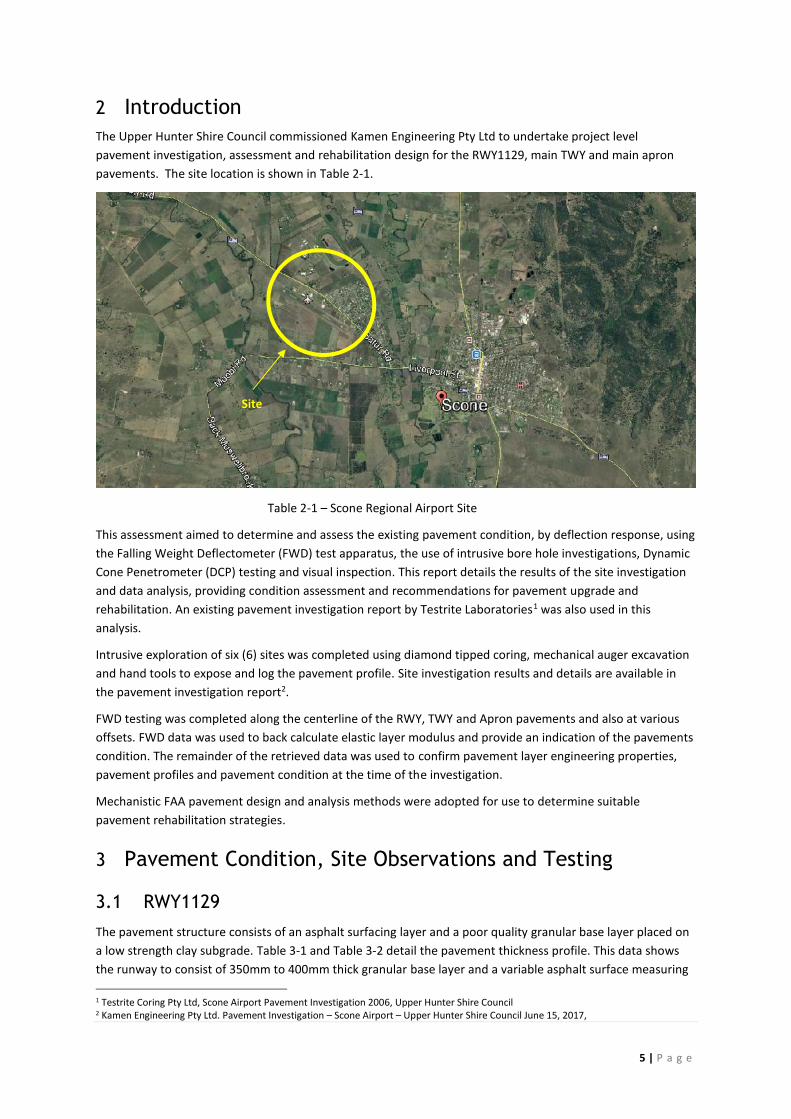
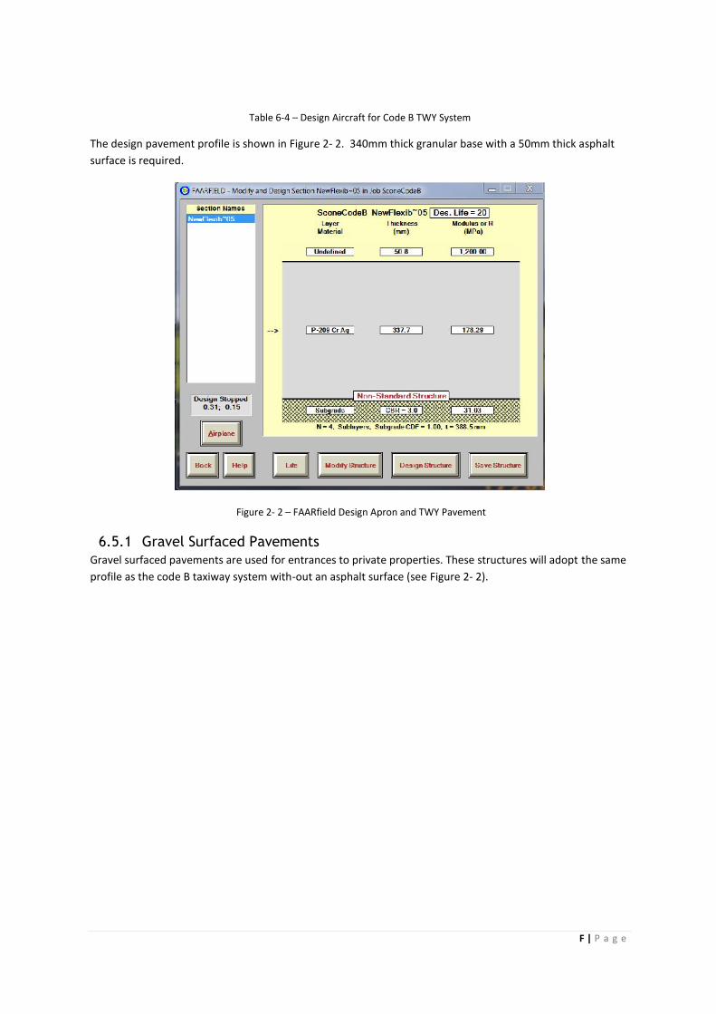
The design pavement profile is shown in Figure 2- 2. 340mm thick granular base with a 50mm thick asphaltsurface is required.
Figure 2- 2 – FAARfield Design Apron and TWY Pavement
6.5.1 Gravel Surfaced PavementsGravel surfaced pavements are used for entrances to private properties. These structures will adopt the sameprofile as the code B taxiway system with-out an asphalt surface (see Figure 2- 2).