PAVEMENT CONDITION SURVEYS. Instructional Objectives n Need for condition surveys n Collection...
44
PAVEMENT CONDITION SURVEYS
-
Upload
beatrice-wells -
Category
Documents
-
view
223 -
download
1
Transcript of PAVEMENT CONDITION SURVEYS. Instructional Objectives n Need for condition surveys n Collection...

PAVEMENT CONDITION SURVEYS
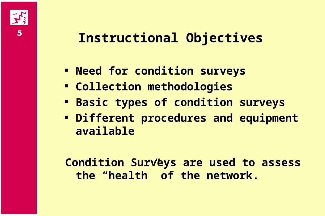
Instructional Objectives
Need for condition surveys Collection methodologies Basic types of condition surveys Different procedures and equipment
available
Condition Surveys are used to assess the “health” of the network.
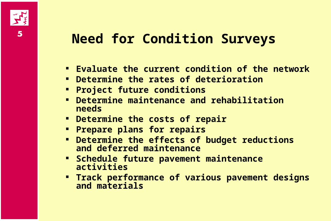
Need for Condition Surveys
Evaluate the current condition of the network Determine the rates of deterioration Project future conditions Determine maintenance and rehabilitation needs Determine the costs of repair Prepare plans for repairs Determine the effects of budget reductions and
deferred maintenance Schedule future pavement maintenance activities Track performance of various pavement designs
and materials
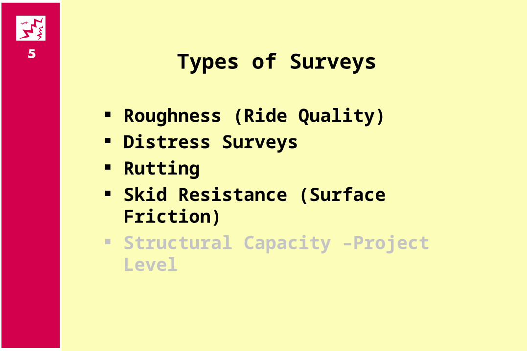
Types of Surveys
Roughness (Ride Quality) Distress Surveys Rutting Skid Resistance (Surface Friction) Structural Capacity –Project Level
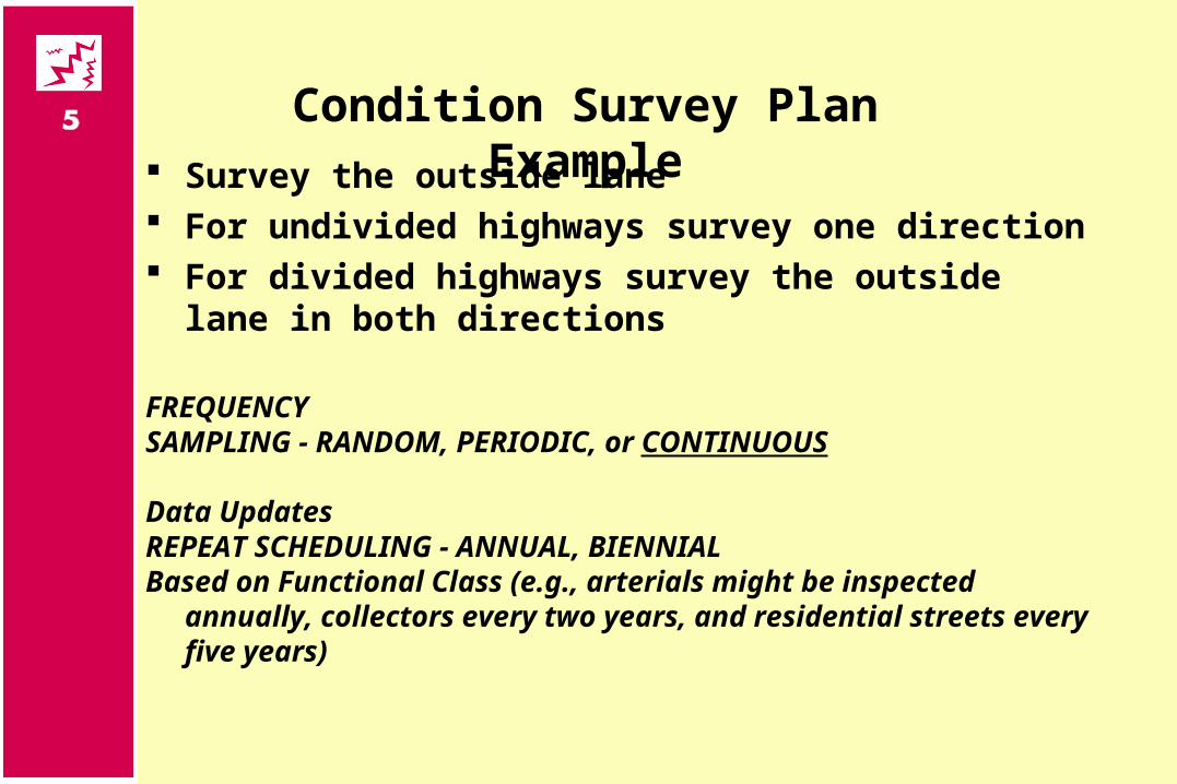
Survey the outside lane For undivided highways survey one direction For divided highways survey the outside lane in both
directions
FREQUENCYSAMPLING - RANDOM, PERIODIC, or CONTINUOUS
Data UpdatesREPEAT SCHEDULING - ANNUAL, BIENNIALBased on Functional Class (e.g., arterials might be inspected
annually, collectors every two years, and residential streets every five years)
Condition Survey Plan Example
Good pavement distress survey will collect data necessary to:
• Identify roads which need no immediate maintenance and therefore, no immediate expenditures• Identify roads which require a minor or routine maintenance and immediate expenditures• Identify roads which require pavement preservation activities such as seal, Micro Surfacing, etc• Identify roads which need minor rehabilitation, major rehabilitation or reconstruction
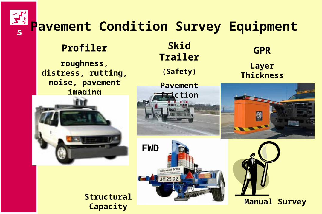
Pavement Condition Survey Equipment
Profiler
roughness, distress, rutting, noise, pavement
imaging
FWD
Skid Trailer
(Safety)
Pavement friction
GPR
Layer Thickness
Structural CapacityManual Survey
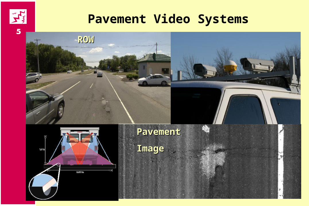
Pavement Video Systems
ROWROW
PavementPavement
ImageImage
PROTOCOL DEFINITION
A procedure for the objective measurement of a pavement characteristic which defines a minimum standard and a set of parameters regarding the type, precision, quantity, location, reporting, and quality of a measurement to be made
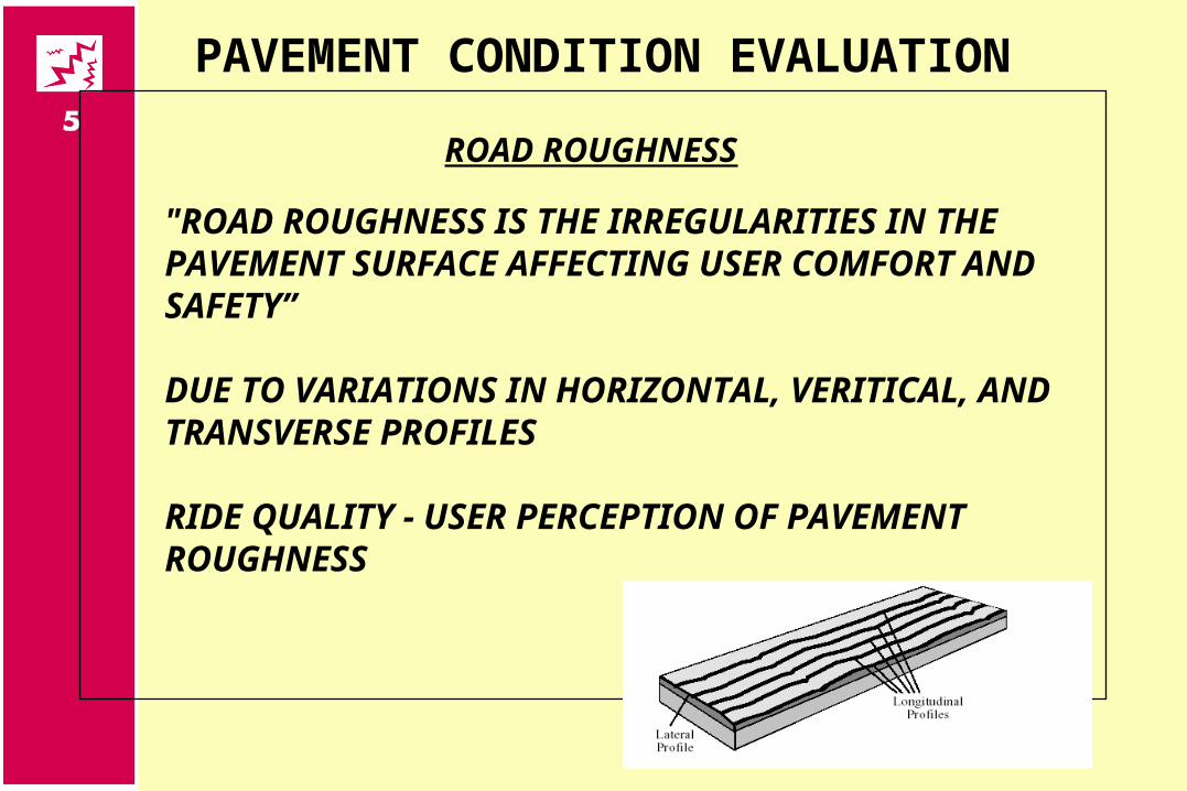
PAVEMENT CONDITION EVALUATION
ROAD ROUGHNESS
"ROAD ROUGHNESS IS THE IRREGULARITIES IN THE PAVEMENT SURFACE AFFECTING USER COMFORT AND SAFETY”
DUE TO VARIATIONS IN HORIZONTAL, VERITICAL, AND TRANSVERSE PROFILES
RIDE QUALITY - USER PERCEPTION OF PAVEMENT ROUGHNESS
IRI ROUGHNESS PROTOCOL
IRI is calculated from longitudinal profile measured with a road profiler in both wheelpaths. The average IRI of the two wheelpaths is reported as the roughness of the pavement section.
International Roughness Index (IRI) - The IRI is computed from a single longitudinal profile using a quarter-car simulation
Little Book of Profiling
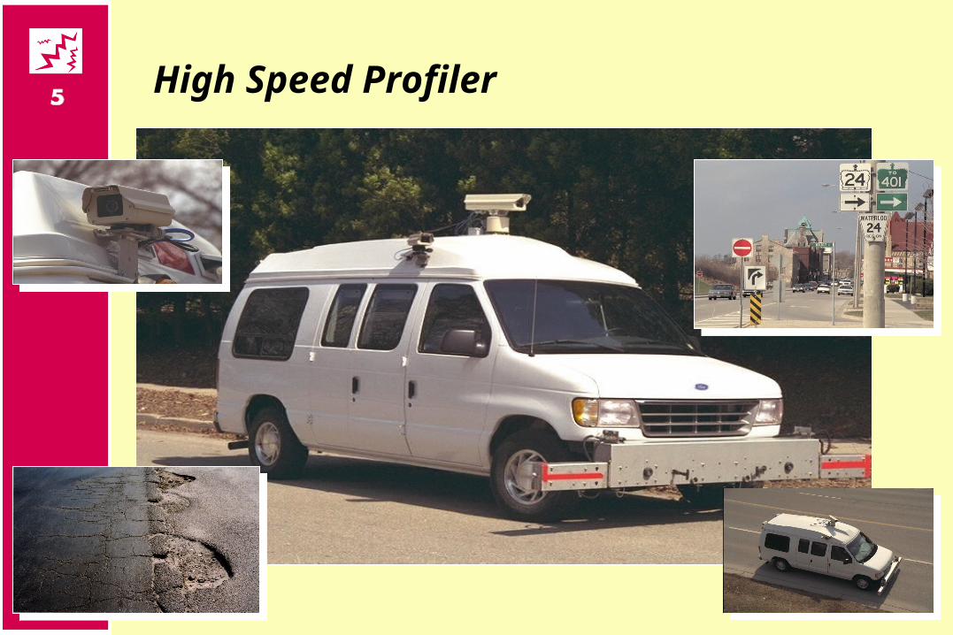
High Speed Profiler
PAVEMENT CONDITION EVALUATION
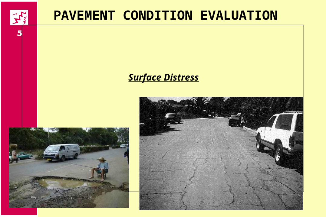
Surface Distress
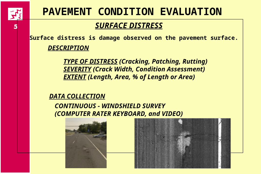
PAVEMENT CONDITION EVALUATIONSURFACE DISTRESS
DATA COLLECTION
CONTINUOUS - WINDSHIELD SURVEY(COMPUTER RATER KEYBOARD, and VIDEO)
DESCRIPTION
TYPE OF DISTRESS (Cracking, Patching, Rutting)SEVERITY (Crack Width, Condition Assessment)EXTENT (Length, Area, % of Length or Area)
Surface distress is damage observed on the pavement surface.
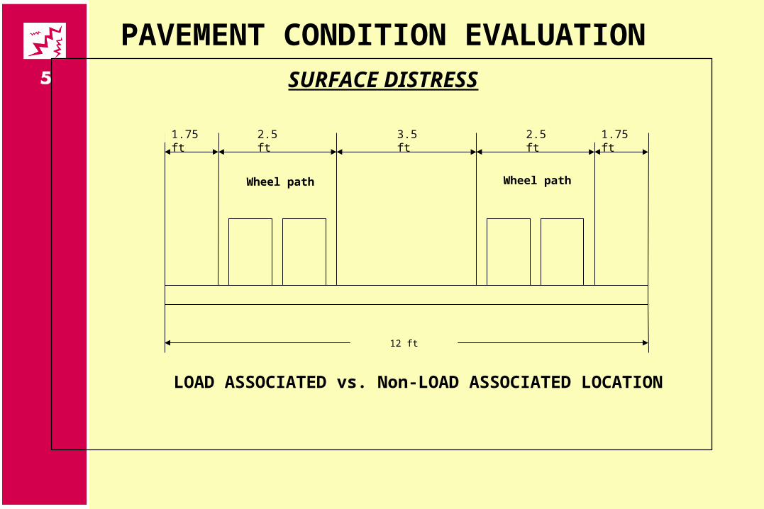
PAVEMENT CONDITION EVALUATIONSURFACE DISTRESS
LOAD ASSOCIATED vs. Non-LOAD ASSOCIATED LOCATION
12 ft
1.75 ft 2.5 ft 2.5 ft3.5 ft 1.75 ft
Wheel path Wheel path
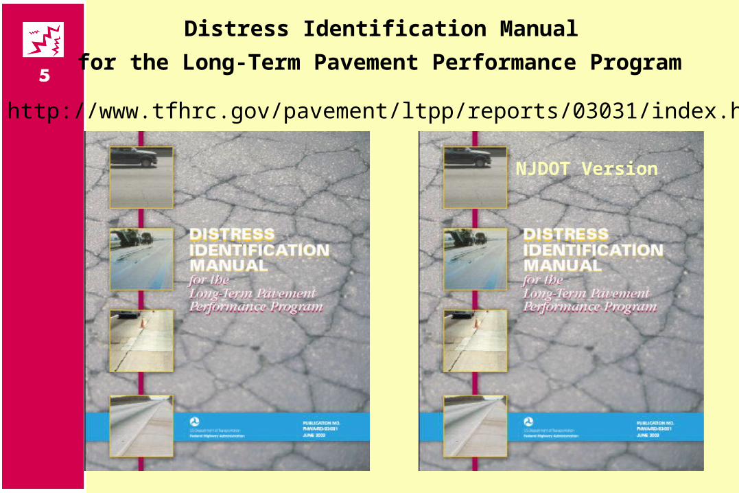
Distress Identification Manual
for the Long-Term Pavement Performance Program
http://www.tfhrc.gov/pavement/ltpp/reports/03031/index.htm
NJDOT Version
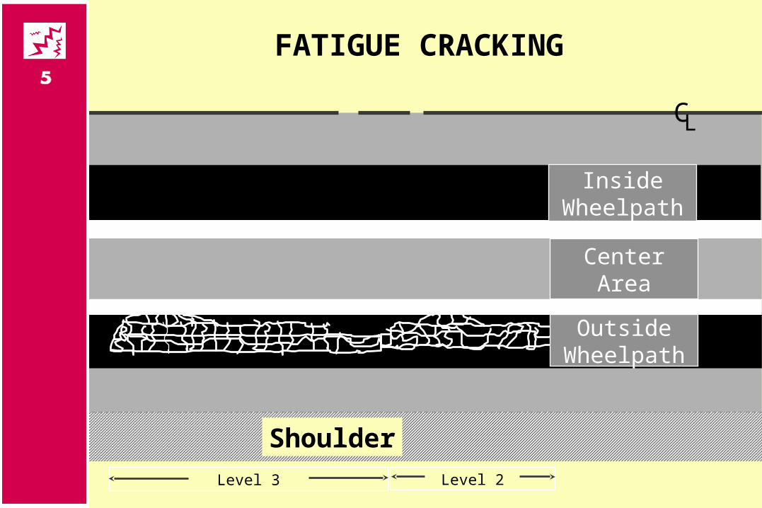
FATIGUE CRACKING
Level 2Level 3
CL
Shoulder
CenterArea
Inside Wheelpath
Outside Wheelpath
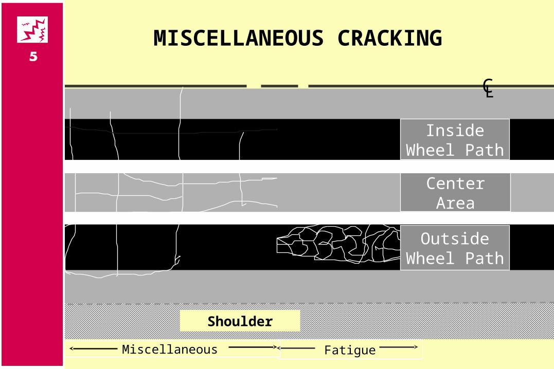
MISCELLANEOUS CRACKING
CL
Shoulder
FatigueMiscellaneous
OutsideWheel Path
Center Area
InsideWheel Path
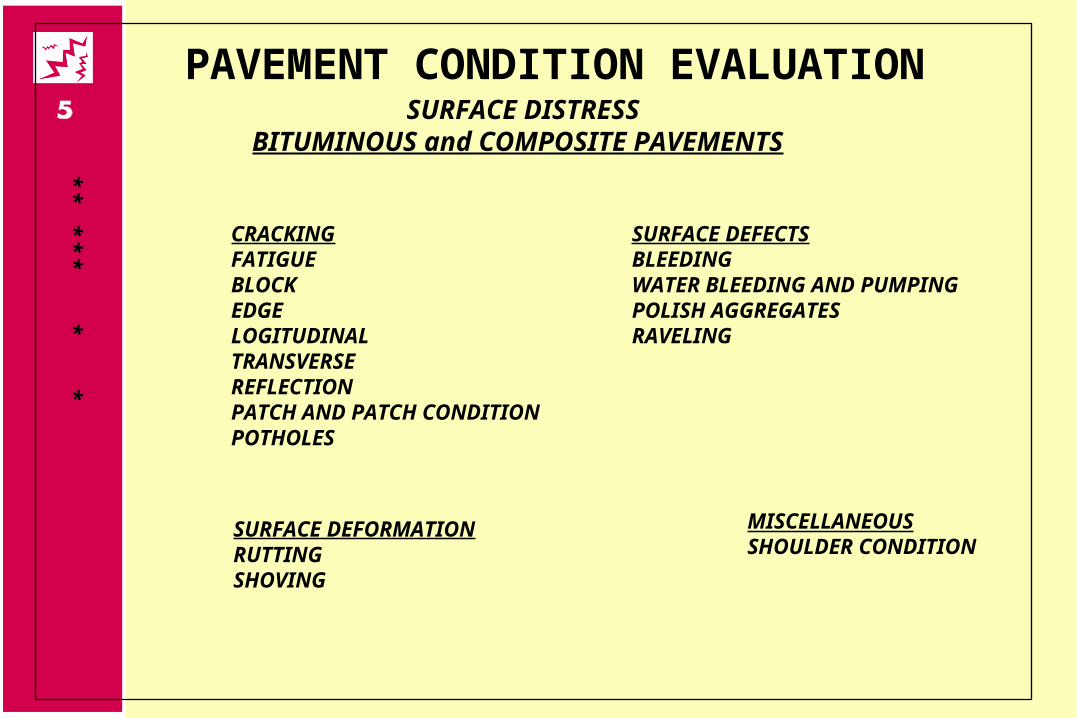
PAVEMENT CONDITION EVALUATIONSURFACE DISTRESS
BITUMINOUS and COMPOSITE PAVEMENTS
*
CRACKINGFATIGUEBLOCKEDGELOGITUDINALTRANSVERSEREFLECTIONPATCH AND PATCH CONDITIONPOTHOLES
*
***
*
SURFACE DEFORMATIONRUTTINGSHOVING
*
SURFACE DEFECTSBLEEDINGWATER BLEEDING AND PUMPINGPOLISH AGGREGATESRAVELING
MISCELLANEOUSSHOULDER CONDITION
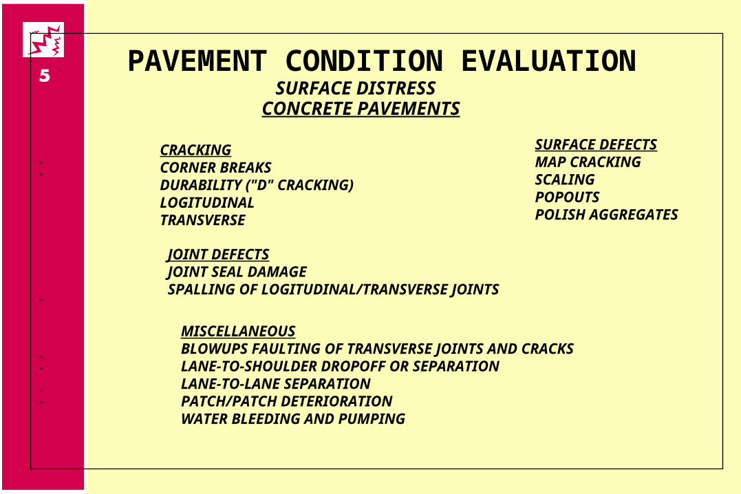
PAVEMENT CONDITION EVALUATIONSURFACE DISTRESS
CONCRETE PAVEMENTS
CRACKINGCORNER BREAKSDURABILITY ("D" CRACKING)LOGITUDINALTRANSVERSE
*
*
SURFACE DEFECTSMAP CRACKINGSCALINGPOPOUTSPOLISH AGGREGATES
JOINT DEFECTSJOINT SEAL DAMAGESPALLING OF LOGITUDINAL/TRANSVERSE JOINTS
*
MISCELLANEOUSBLOWUPS FAULTING OF TRANSVERSE JOINTS AND CRACKSLANE-TO-SHOULDER DROPOFF OR SEPARATIONLANE-TO-LANE SEPARATIONPATCH/PATCH DETERIORATIONWATER BLEEDING AND PUMPING
*
*
*
*
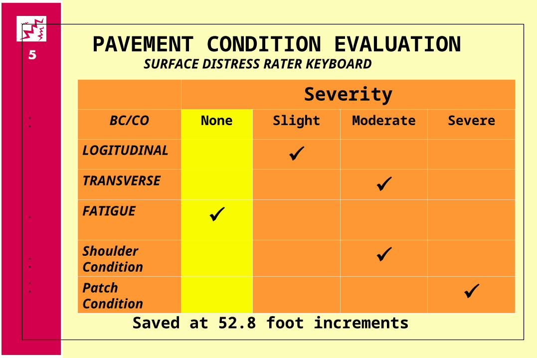
PAVEMENT CONDITION EVALUATIONSURFACE DISTRESS RATER KEYBOARD
*
*
*
*
*
*
*
SeverityBC/CO None Slight Moderate Severe
LOGITUDINAL TRANSVERSE FATIGUE Shoulder Condition
Patch Condition
Saved at 52.8 foot increments

PAVEMENT CONDITION EVALUATIONSURFACE DISTRESS RATER FORM
*
*
*
*
*
*
*
SeverityBC/CO None Slight Moderate Severe
LOGITUDINAL TRANSVERSE FATIGUE Shoulder Condition
Patch Condition
Summary for Street Link
Distress Data Collection
Visual survey Laser technology Film-based systems Video systems
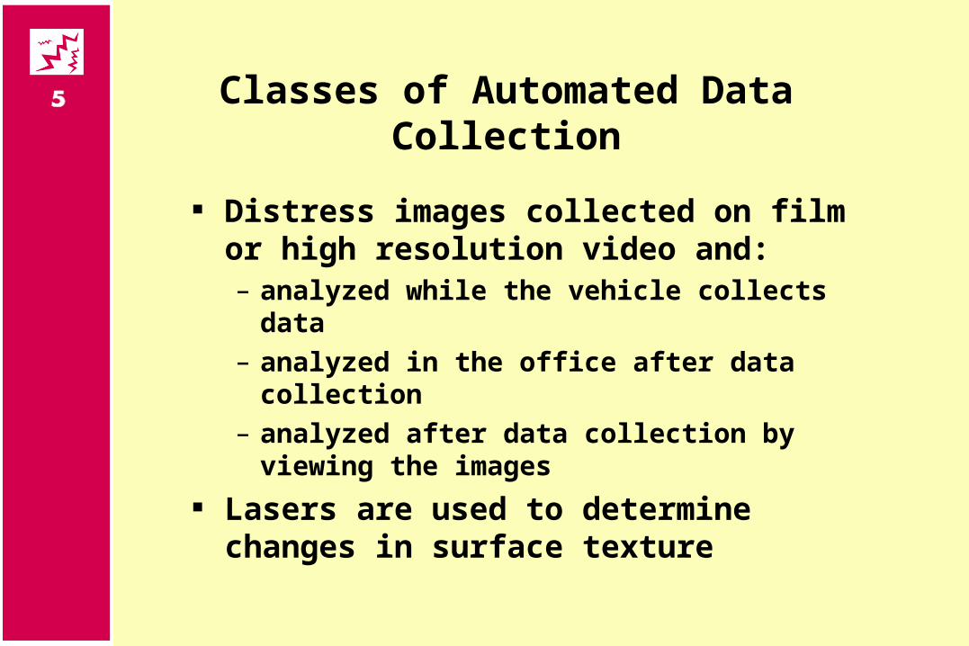
Classes of Automated Data Collection
Distress images collected on film or high resolution video and:– analyzed while the vehicle collects data– analyzed in the office after data collection– analyzed after data collection by viewing the
images Lasers are used to determine changes in
surface texture
Automated Distress Surveys
Increase speed and ease of data collection
Reduce transcription errors Increase consistency between
classification and quantification Increase safety of field crews
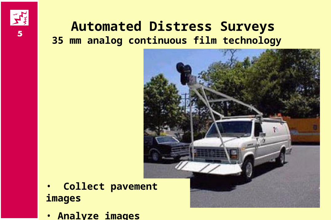
Automated Distress Surveys
• Collect pavement images
• Analyze images
35 mm analog continuous film technology
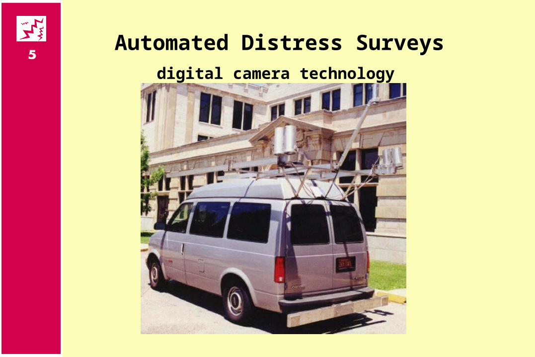
Automated Distress Surveysdigital camera technology
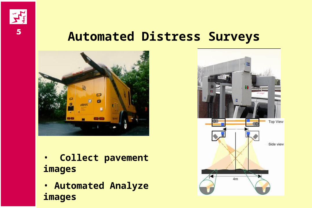
Automated Distress Surveys
• Collect pavement images
• Automated Analyze images
PAVEMENT CONDITION EVALUATION
Rutting
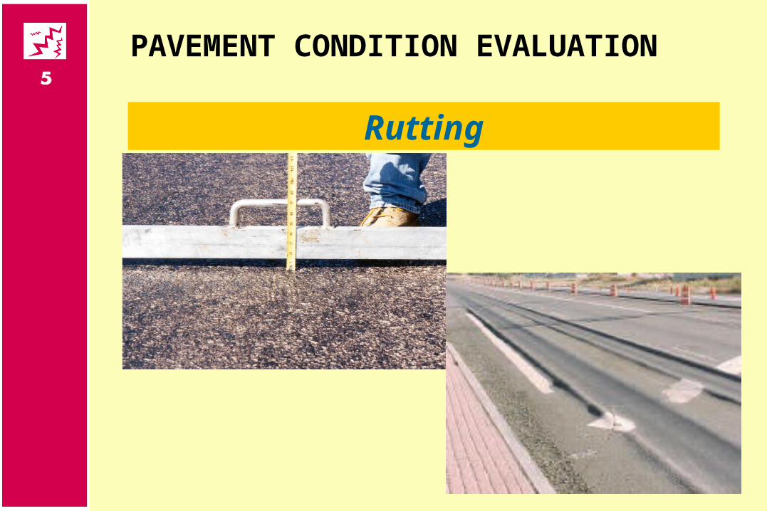
Rutting
PAVEMENT CONDITION EVALUATION
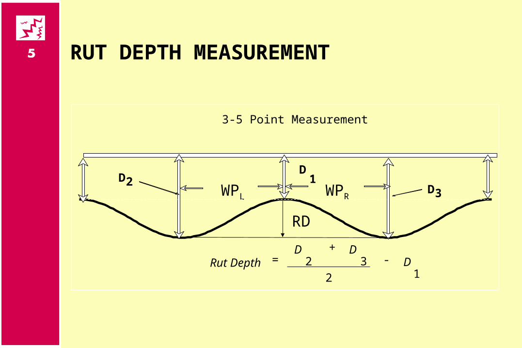
3-5 Point Measurement
Rut DepthD D
D=+
-2 312
D2D
1D3
RUT DEPTH MEASUREMENT
WPL WPR
RD
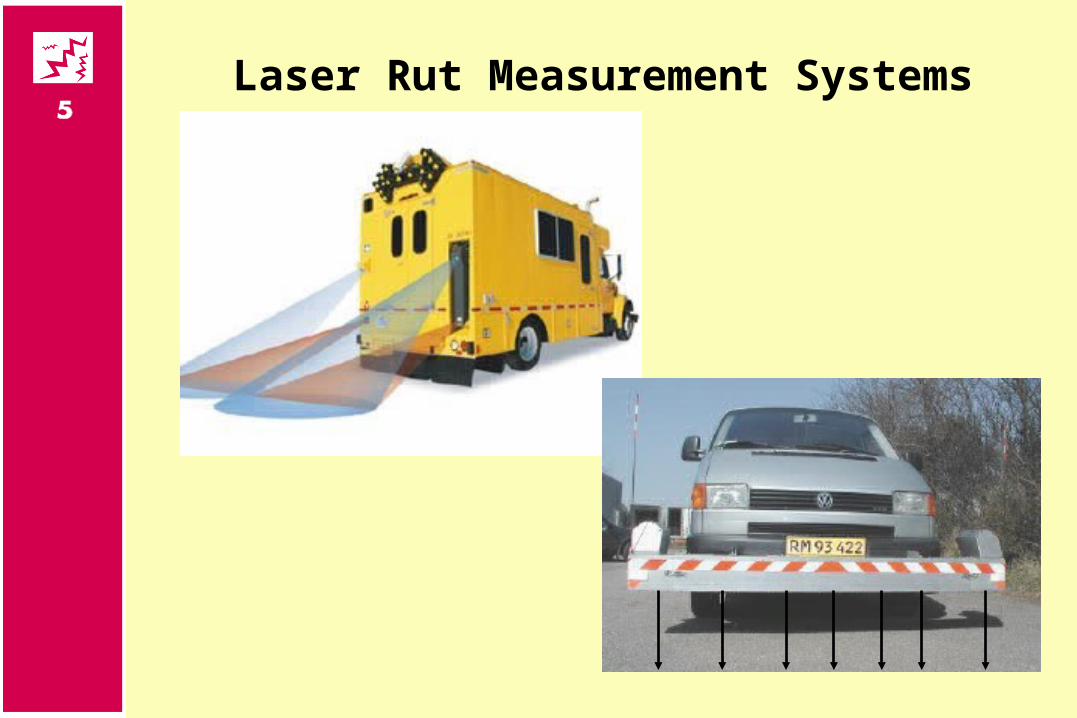
Laser Rut Measurement Systems
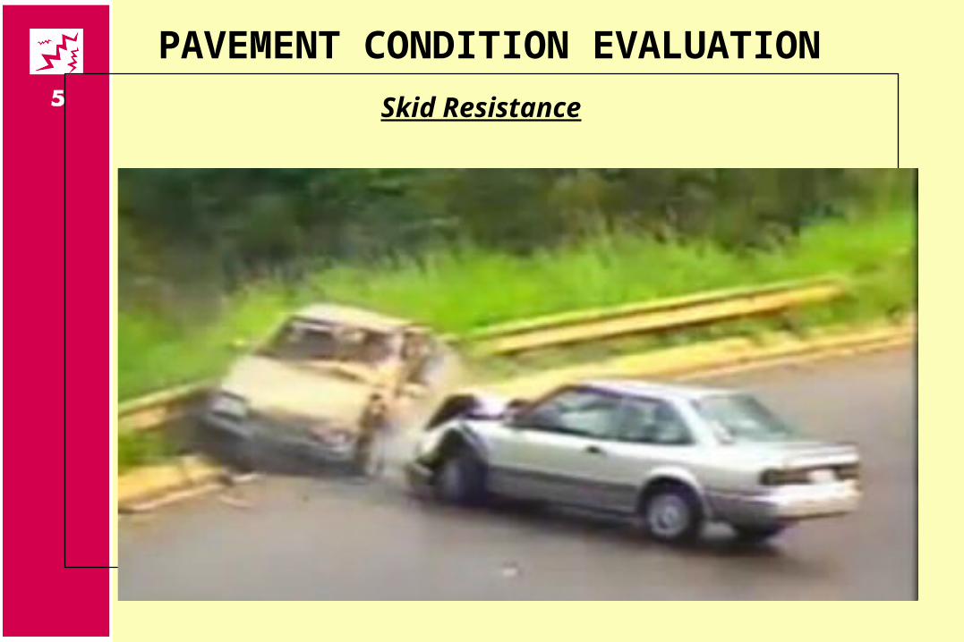
PAVEMENT CONDITION EVALUATION
Skid Resistance
PAVEMENT CONDITION EVALUATION
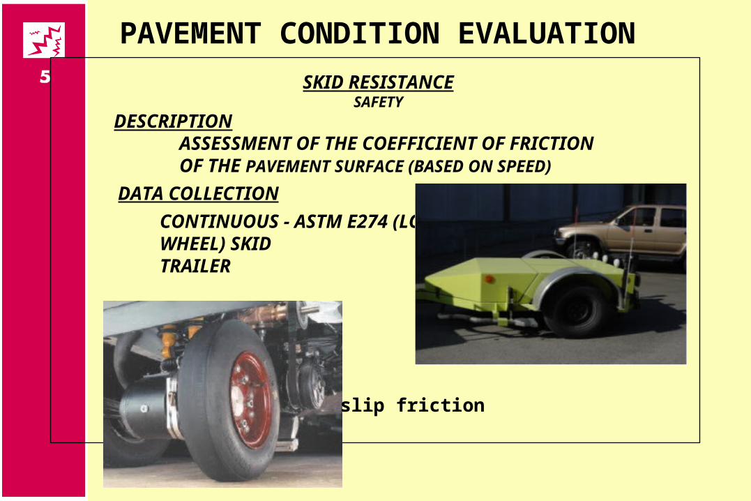
SKID RESISTANCESAFETY
DESCRIPTIONASSESSMENT OF THE COEFFICIENT OF FRICTION OF THE PAVEMENT SURFACE (BASED ON SPEED)
DATA COLLECTION
CONTINUOUS - ASTM E274 (LOCK WHEEL) SKID TRAILER
slip friction
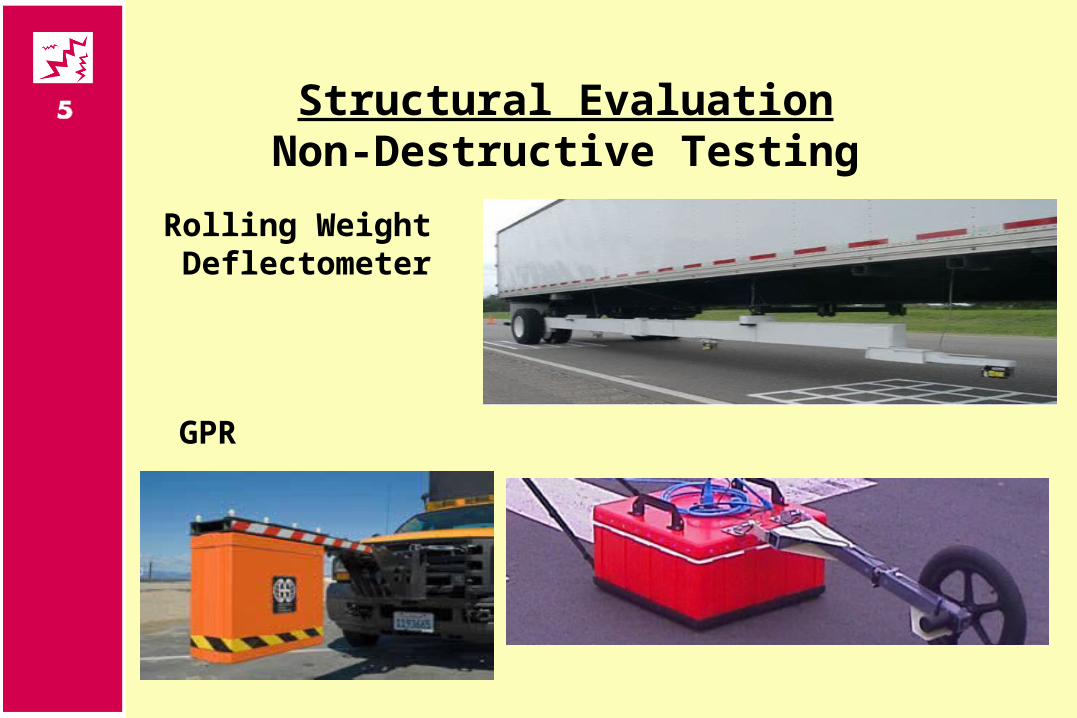
Structural EvaluationNon-Destructive Testing
GPR
Rolling Weight Deflectometer
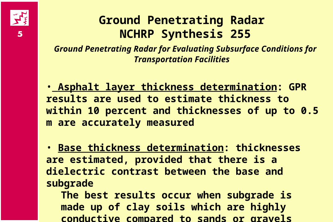
Ground Penetrating Radar NCHRP Synthesis 255
Ground Penetrating Radar for Evaluating Subsurface Conditions for Transportation Facilities
• Asphalt layer thickness determination: GPR results are used to estimate thickness to within 10 percent and thicknesses of up to 0.5 m are accurately measured
• Base thickness determination: thicknesses are estimated, provided that there is a dielectric contrast between the base and subgrade
The best results occur when subgrade is made up of clay soils which are highly conductive compared to sands or gravels
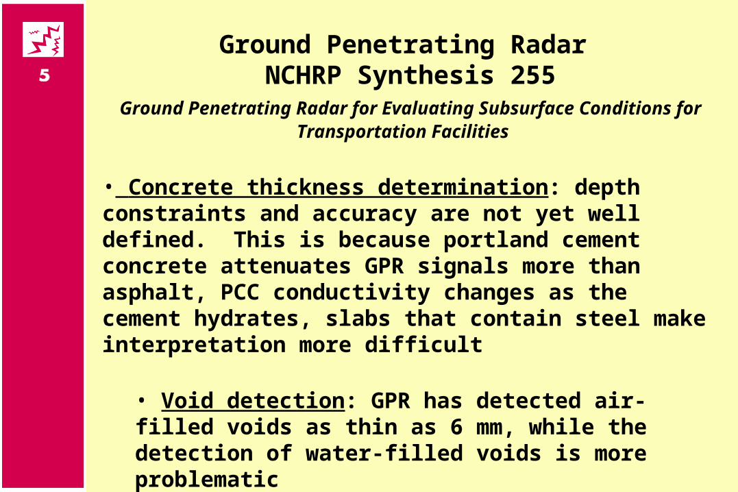
Ground Penetrating Radar NCHRP Synthesis 255
Ground Penetrating Radar for Evaluating Subsurface Conditions for Transportation Facilities
• Concrete thickness determination: depth constraints and accuracy are not yet well defined. This is because portland cement concrete attenuates GPR signals more than asphalt, PCC conductivity changes as the cement hydrates, slabs that contain steel make interpretation more difficult
• Void detection: GPR has detected air-filled voids as thin as 6 mm, while the detection of water-filled voids is more problematic
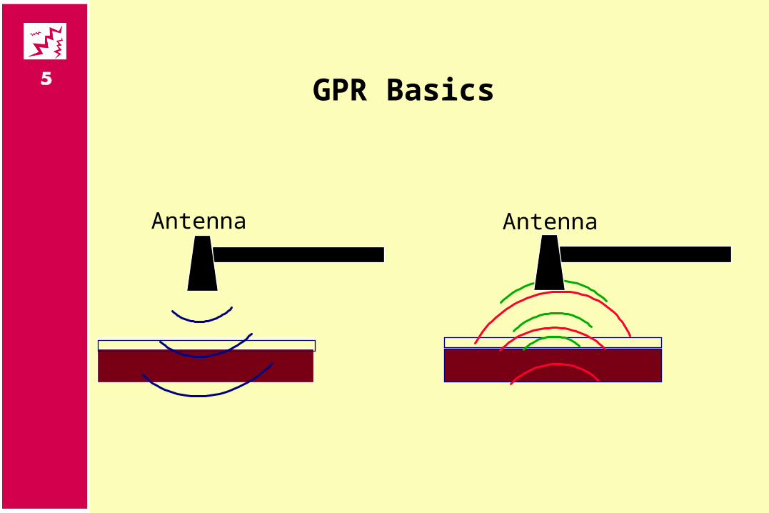
GPR Basics
Antenna Antenna
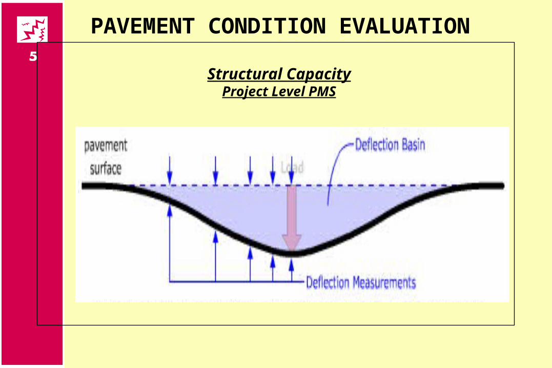
PAVEMENT CONDITION EVALUATION
Structural CapacityProject Level PMS
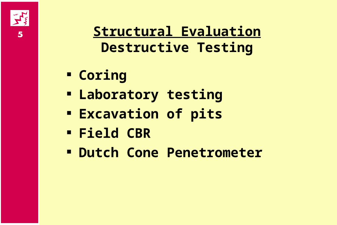
Structural EvaluationDestructive Testing
Coring Laboratory testing Excavation of pits Field CBR Dutch Cone Penetrometer
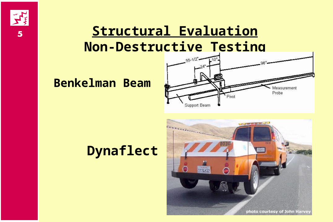
Structural EvaluationNon-Destructive Testing
Benkelman Beam
Dynaflect

Structural EvaluationNon-Destructive Testing
Road Rater
FWD
PAVEMENT CONDITION EVALUATION
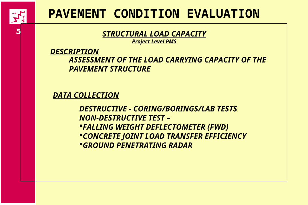
STRUCTURAL LOAD CAPACITYProject Level PMS
DESCRIPTIONASSESSMENT OF THE LOAD CARRYING CAPACITY OF THE PAVEMENT STRUCTURE
DATA COLLECTION
DESTRUCTIVE - CORING/BORINGS/LAB TESTS NON-DESTRUCTIVE TEST – FALLING WEIGHT DEFLECTOMETER (FWD)CONCRETE JOINT LOAD TRANSFER EFFICIENCYGROUND PENETRATING RADAR

Questions?

![Request for Proposals Bermuda Schools Condition Surveys ......Request for Proposals Bermuda Schools Condition Surveys [28 Schools] ... 4 S0063 Port Royal Primary School 6 Church Road](https://static.fdocuments.in/doc/165x107/5ea07e8f5f004576f9284ad5/request-for-proposals-bermuda-schools-condition-surveys-request-for-proposals.jpg)