Patterned nanofiber meshes for biomedical applications … · Patterned nanofiber meshes for...
4
Patterned nanofiber meshes for biomedical applications N.M. Neves 1,2 , R. Campos 1,2 , A. Pedro 1,2 , J. Cunha 3 , F. Macedo 3 and R.L. Reis 1,2 1 3B’s Research Group – Biomaterials, Biodegradables and Biomimetics, University of Minho, Campus de Gualtar, 4710-057 Braga, Portugal. 2 Department of Polymer Engineering, University of Minho, Campus de Azurém, 4800- 058 Guimarães, Portugal, [email protected] 3 Department of Physics, University of Minho, Campus de Gualtar, 4710-057 Braga, Portugal ABSTRACT The aim of this work was to prepare nanofibre meshes using various collectors with different geometries and with specific dimensions and to evaluate how those patterns can affect the properties of the meshes. The underlying hypothesis addressed in this study is if it is possible to control the architecture of the fibre meshes by tailoring the geometry of the collector. To test this hypothesis, different collectors were used. Electrospun nonwoven patterned meshes of polyethylene oxide (PEO) and poly( -caprolactone) (PCL) were successfully prepared. Those fibre meshes were imaged with scanning electron microscopy (SEM). Both mechanical properties of the meshes and preliminary cell contacting experiments were performed to test the effect of the produced patterns over the properties of the meshes relevant for biomedical applications. Keywords: nanofiber meshes, electrospinning, biodegradable polymers, tissue engineering ELECTROSPINNING: THE PROCESS The key components of an electrospinning unit include a high voltage power supply connected to a syringe containing the polymeric solution (figure 1). At the open end of the syringe a capillary needle is mounted. The setup can be mounted either with the syringe-needle oriented vertically [1, 2], tilted at a defined angle [3], or horizontally [4]. The flow of the solution through the needle may be controlled by the action of a syringe pump. The pressure- driven flow generates a polymer solution drop at the tip of the needle. At this stage, the voltage can be applied between the needle and the collector. Upon application of the high voltage, a complex state of electrification is applied to the polymer solution causing repulsions that may lead to the development of forces of the order of the surface tension of the solution [5,6]. Upon further increase in the voltage, the solution drop deposited at the tip of the capillary tube elongates. This deformation forms a typical conical shape known as Taylor cone. The repulsive electrostatic force may overcome the surface tension of the fluid forming a jet of fluid that is ejected from the Taylor cone. The other end of the voltage supply unit is connected to a grounded collector plate. This collector may placed at a distance ranging from 10 to 30 cm from the tip. An electric conductor is usually used as collector. Figure 1 The electrospinning apparatus The jet experiences complex bending strains (represented schematically in Figure 1) upon separation from the needle tip. Those strains can be visually observed by using a stroboscope as light source. The strains at the jet cause its elongation into a very long and thin fibre. Typical diameters are in the range of nanometers to micrometers. The polymer solvent initiates evaporating at the moment of ejection, and continues during all the travel and after deposition of the fibres in and around the collector. Upon deposition at the collector, the fibres tend to connect to other fibres by the presence of residual solvent at the moment of deposition, resulting in a non-woven random fabric. More detailed descriptions of the electrospinning process may be found elsewhere [5,7]. Patterned collectors were already proposed in the literature to control the deposition of the fibres [8]. To a limited extent, patterned nanofibre depositions have been obtained by different groups [9,10]. Collector High Voltage Power Supply Solution Syringe Pump Distance NSTI-Nanotech 2006, www.nsti.org, ISBN 0-9767985-7-3 Vol. 2, 2006 155
Transcript of Patterned nanofiber meshes for biomedical applications … · Patterned nanofiber meshes for...
Patterned nanofiber meshes for biomedical applications
N.M. Neves1,2, R. Campos1,2, A. Pedro1,2, J. Cunha3, F. Macedo3 and R.L. Reis1,2
13B’s Research Group – Biomaterials, Biodegradables and Biomimetics, University of Minho, Campus de Gualtar, 4710-057 Braga, Portugal.
2Department of Polymer Engineering, University of Minho, Campus de Azurém, 4800-058 Guimarães, Portugal, [email protected]
3Department of Physics, University of Minho, Campus de Gualtar, 4710-057 Braga, Portugal
ABSTRACT
The aim of this work was to prepare nanofibre meshes using various collectors with different geometries and with specific dimensions and to evaluate how those patterns can affect the properties of the meshes. The underlying hypothesis addressed in this study is if it is possible to control the architecture of the fibre meshes by tailoring the geometry of the collector. To test this hypothesis, different collectors were used. Electrospun nonwoven patterned meshes of polyethylene oxide (PEO) and poly( -caprolactone) (PCL) were successfully prepared. Those fibre meshes were imaged with scanning electron microscopy (SEM). Both mechanical properties of the meshes and preliminary cell contacting experiments were performed to test the effect of the produced patterns over the properties of the meshes relevant for biomedical applications.
Keywords: nanofiber meshes, electrospinning, biodegradable polymers, tissue engineering
ELECTROSPINNING: THE PROCESS
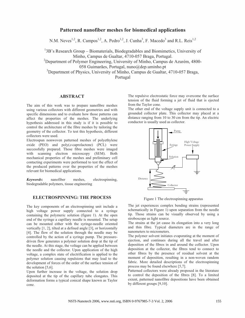
The key components of an electrospinning unit include a high voltage power supply connected to a syringe containing the polymeric solution (figure 1). At the open end of the syringe a capillary needle is mounted. The setup can be mounted either with the syringe-needle oriented vertically [1, 2], tilted at a defined angle [3], or horizontally [4]. The flow of the solution through the needle may be controlled by the action of a syringe pump. The pressure-driven flow generates a polymer solution drop at the tip of the needle. At this stage, the voltage can be applied between the needle and the collector. Upon application of the high voltage, a complex state of electrification is applied to the polymer solution causing repulsions that may lead to the development of forces of the order of the surface tension of the solution [5,6]. Upon further increase in the voltage, the solution drop deposited at the tip of the capillary tube elongates. This deformation forms a typical conical shape known as Taylor cone.
The repulsive electrostatic force may overcome the surface tension of the fluid forming a jet of fluid that is ejected from the Taylor cone. The other end of the voltage supply unit is connected to a grounded collector plate. This collector may placed at a distance ranging from 10 to 30 cm from the tip. An electric conductor is usually used as collector.
Figure 1 The electrospinning apparatus
The jet experiences complex bending strains (represented schematically in Figure 1) upon separation from the needle tip. Those strains can be visually observed by using a stroboscope as light source. The strains at the jet cause its elongation into a very long and thin fibre. Typical diameters are in the range of nanometers to micrometers. The polymer solvent initiates evaporating at the moment of ejection, and continues during all the travel and after deposition of the fibres in and around the collector. Upon deposition at the collector, the fibres tend to connect to other fibres by the presence of residual solvent at the moment of deposition, resulting in a non-woven random fabric. More detailed descriptions of the electrospinning process may be found elsewhere [5,7]. Patterned collectors were already proposed in the literature to control the deposition of the fibres [8]. To a limited extent, patterned nanofibre depositions have been obtained by different groups [9,10].
Collector
High Voltage Power Supply
Solution
Syringe
Pump
Distance
NSTI-Nanotech 2006, www.nsti.org, ISBN 0-9767985-7-3 Vol. 2, 2006 155
However, to our best knowledge, the production by electrospinning of patterned meshes with controlled and functional morphology, both mechanically and biologically, was not yet reported in literature.
MATERIALS & METHODS
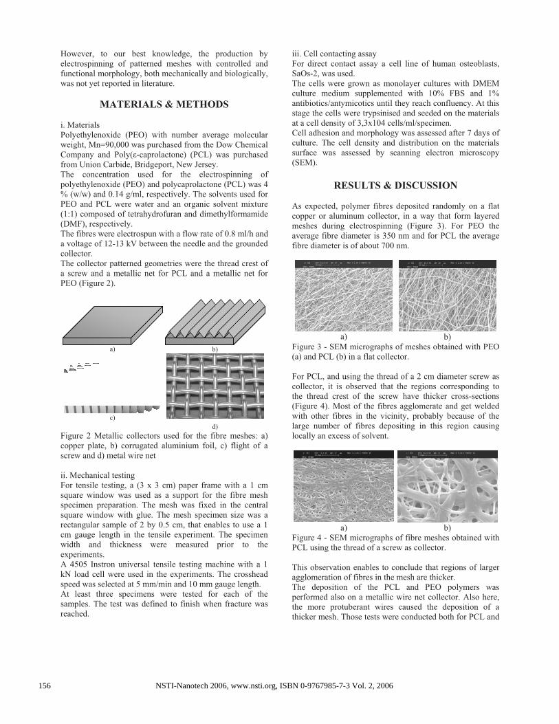
i. MaterialsPolyethylenoxide (PEO) with number average molecular weight, Mn=90,000 was purchased from the Dow Chemical Company and Poly( -caprolactone) (PCL) was purchased from Union Carbide, Bridgeport, New Jersey. The concentration used for the electrospinning of polyethylenoxide (PEO) and polycaprolactone (PCL) was 4 % (w/w) and 0.14 g/ml, respectively. The solvents used for PEO and PCL were water and an organic solvent mixture (1:1) composed of tetrahydrofuran and dimethylformamide (DMF), respectively. The fibres were electrospun with a flow rate of 0.8 ml/h and a voltage of 12-13 kV between the needle and the grounded collector.The collector patterned geometries were the thread crest of a screw and a metallic net for PCL and a metallic net for PEO (Figure 2).
a) b)
c)d)
Figure 2 Metallic collectors used for the fibre meshes: a) copper plate, b) corrugated aluminium foil, c) flight of a screw and d) metal wire net
ii. Mechanical testing For tensile testing, a (3 x 3 cm) paper frame with a 1 cm square window was used as a support for the fibre mesh specimen preparation. The mesh was fixed in the central square window with glue. The mesh specimen size was a rectangular sample of 2 by 0.5 cm, that enables to use a 1 cm gauge length in the tensile experiment. The specimen width and thickness were measured prior to the experiments. A 4505 Instron universal tensile testing machine with a 1 kN load cell were used in the experiments. The crosshead speed was selected at 5 mm/min and 10 mm gauge length. At least three specimens were tested for each of the samples. The test was defined to finish when fracture was reached.
iii. Cell contacting assay For direct contact assay a cell line of human osteoblasts, SaOs-2, was used. The cells were grown as monolayer cultures with DMEM culture medium supplemented with 10% FBS and 1% antibiotics/antymicotics until they reach confluency. At this stage the cells were trypsinised and seeded on the materials at a cell density of 3,3x10⁴ cells/ml/specimen. Cell adhesion and morphology was assessed after 7 days of culture. The cell density and distribution on the materials surface was assessed by scanning electron microscopy (SEM).
RESULTS & DISCUSSION
As expected, polymer fibres deposited randomly on a flat copper or aluminum collector, in a way that form layered meshes during electrospinning (Figure 3). For PEO the average fibre diameter is 350 nm and for PCL the average fibre diameter is of about 700 nm.
a) b)Figure 3 - SEM micrographs of meshes obtained with PEO (a) and PCL (b) in a flat collector.
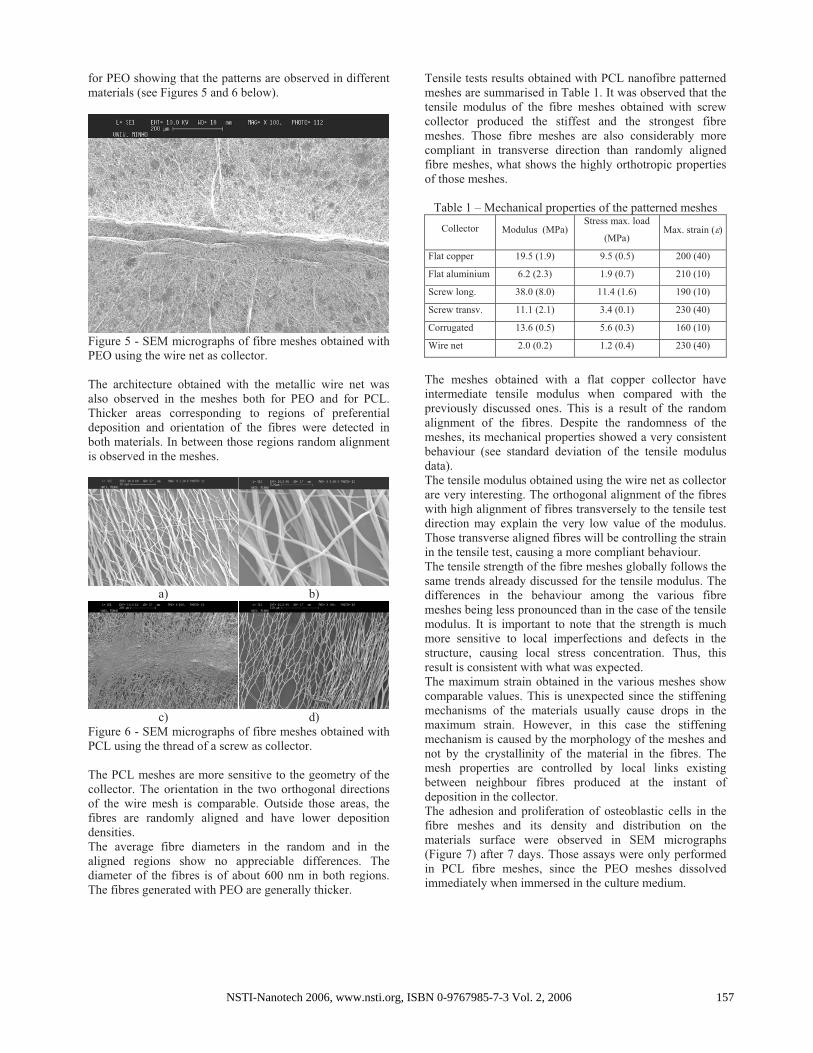
For PCL, and using the thread of a 2 cm diameter screw as collector, it is observed that the regions corresponding to the thread crest of the screw have thicker cross-sections (Figure 4). Most of the fibres agglomerate and get welded with other fibres in the vicinity, probably because of the large number of fibres depositing in this region causing locally an excess of solvent.
a) b) Figure 4 - SEM micrographs of fibre meshes obtained with PCL using the thread of a screw as collector.
This observation enables to conclude that regions of larger agglomeration of fibres in the mesh are thicker. The deposition of the PCL and PEO polymers was performed also on a metallic wire net collector. Also here, the more protuberant wires caused the deposition of a thicker mesh. Those tests were conducted both for PCL and
NSTI-Nanotech 2006, www.nsti.org, ISBN 0-9767985-7-3 Vol. 2, 2006156
for PEO showing that the patterns are observed in different materials (see Figures 5 and 6 below).
Figure 5 - SEM micrographs of fibre meshes obtained with PEO using the wire net as collector.
The architecture obtained with the metallic wire net was also observed in the meshes both for PEO and for PCL. Thicker areas corresponding to regions of preferential deposition and orientation of the fibres were detected in both materials. In between those regions random alignment is observed in the meshes.
a) b)
c) d) Figure 6 - SEM micrographs of fibre meshes obtained with PCL using the thread of a screw as collector.
The PCL meshes are more sensitive to the geometry of the collector. The orientation in the two orthogonal directions of the wire mesh is comparable. Outside those areas, the fibres are randomly aligned and have lower deposition densities. The average fibre diameters in the random and in the aligned regions show no appreciable differences. The diameter of the fibres is of about 600 nm in both regions. The fibres generated with PEO are generally thicker.
Tensile tests results obtained with PCL nanofibre patterned meshes are summarised in Table 1. It was observed that the tensile modulus of the fibre meshes obtained with screw collector produced the stiffest and the strongest fibre meshes. Those fibre meshes are also considerably more compliant in transverse direction than randomly aligned fibre meshes, what shows the highly orthotropic properties of those meshes.
Table 1 – Mechanical properties of the patterned meshes
Collector Modulus (MPa) Stress max. load
(MPa) Max. strain ( )
Flat copper 19.5 (1.9) 9.5 (0.5) 200 (40)
Flat aluminium 6.2 (2.3) 1.9 (0.7) 210 (10)
Screw long. 38.0 (8.0) 11.4 (1.6) 190 (10)
Screw transv. 11.1 (2.1) 3.4 (0.1) 230 (40)
Corrugated 13.6 (0.5) 5.6 (0.3) 160 (10)
Wire net 2.0 (0.2) 1.2 (0.4) 230 (40)
The meshes obtained with a flat copper collector have intermediate tensile modulus when compared with the previously discussed ones. This is a result of the random alignment of the fibres. Despite the randomness of the meshes, its mechanical properties showed a very consistent behaviour (see standard deviation of the tensile modulus data). The tensile modulus obtained using the wire net as collector are very interesting. The orthogonal alignment of the fibres with high alignment of fibres transversely to the tensile test direction may explain the very low value of the modulus. Those transverse aligned fibres will be controlling the strain in the tensile test, causing a more compliant behaviour. The tensile strength of the fibre meshes globally follows the same trends already discussed for the tensile modulus. The differences in the behaviour among the various fibre meshes being less pronounced than in the case of the tensile modulus. It is important to note that the strength is much more sensitive to local imperfections and defects in the structure, causing local stress concentration. Thus, this result is consistent with what was expected. The maximum strain obtained in the various meshes show comparable values. This is unexpected since the stiffening mechanisms of the materials usually cause drops in the maximum strain. However, in this case the stiffening mechanism is caused by the morphology of the meshes and not by the crystallinity of the material in the fibres. The mesh properties are controlled by local links existing between neighbour fibres produced at the instant of deposition in the collector. The adhesion and proliferation of osteoblastic cells in the fibre meshes and its density and distribution on the materials surface were observed in SEM micrographs (Figure 7) after 7 days. Those assays were only performed in PCL fibre meshes, since the PEO meshes dissolved immediately when immersed in the culture medium.
NSTI-Nanotech 2006, www.nsti.org, ISBN 0-9767985-7-3 Vol. 2, 2006 157
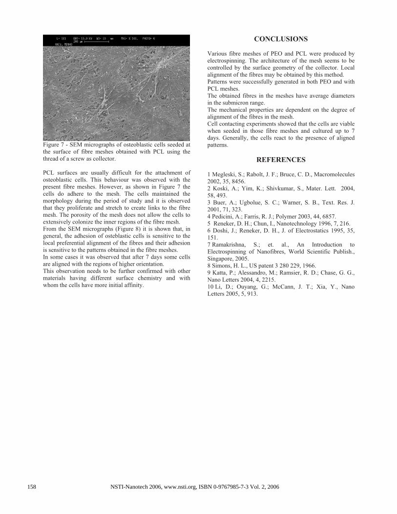
Figure 7 - SEM micrographs of osteoblastic cells seeded at the surface of fibre meshes obtained with PCL using the thread of a screw as collector.
PCL surfaces are usually difficult for the attachment of osteoblastic cells. This behaviour was observed with the present fibre meshes. However, as shown in Figure 7 the cells do adhere to the mesh. The cells maintained the morphology during the period of study and it is observed that they proliferate and stretch to create links to the fibre mesh. The porosity of the mesh does not allow the cells to extensively colonize the inner regions of the fibre mesh. From the SEM micrographs (Figure 8) it is shown that, in general, the adhesion of osteblastic cells is sensitive to the local preferential alignment of the fibres and their adhesion is sensitive to the patterns obtained in the fibre meshes. In some cases it was observed that after 7 days some cells are aligned with the regions of higher orientation. This observation needs to be further confirmed with other materials having different surface chemistry and with whom the cells have more initial affinity.
CONCLUSIONS
Various fibre meshes of PEO and PCL were produced by electrospinning. The architecture of the mesh seems to be controlled by the surface geometry of the collector. Local alignment of the fibres may be obtained by this method. Patterns were successfully generated in both PEO and with PCL meshes. The obtained fibres in the meshes have average diameters in the submicron range. The mechanical properties are dependent on the degree of alignment of the fibres in the mesh. Cell contacting experiments showed that the cells are viable when seeded in those fibre meshes and cultured up to 7 days. Generally, the cells react to the presence of aligned patterns.
REFERENCES
1 Megleski, S.; Rabolt, J. F.; Bruce, C. D., Macromolecules 2002, 35, 8456. 2 Koski, A.; Yim, K.; Shivkumar, S., Mater. Lett. 2004, 58, 493. 3 Buer, A.; Ugbolue, S. C.; Warner, S. B., Text. Res. J. 2001, 71, 323. 4 Pedicini, A.; Farris, R. J.; Polymer 2003, 44, 6857. 5 Reneker, D. H.; Chun, I., Nanotechnology 1996, 7, 216. 6 Doshi, J.; Reneker, D. H., J. of Electrostatics 1995, 35, 151. 7 Ramakrishna, S.; et. al., An Introduction to Electrospinning of Nanofibres, World Scientific Publish., Singapore, 2005. 8 Simons, H. L., US patent 3 280 229, 1966. 9 Katta, P.; Alessandro, M.; Ramsier, R. D.; Chase, G. G., Nano Letters 2004, 4, 2215. 10 Li, D.; Ouyang, G.; McCann, J. T.; Xia, Y., Nano Letters 2005, 5, 913.
NSTI-Nanotech 2006, www.nsti.org, ISBN 0-9767985-7-3 Vol. 2, 2006158