Patrick Dempsey Bridget Fitzpatrick Heather Garber Keith Hout Jong Soo Mok
66
description
ORION AEROSPACE. Final Design review December 5, 2000. Patrick Dempsey Bridget Fitzpatrick Heather Garber Keith Hout Jong Soo Mok. ORION AEROSPACE. Presentation Overview. -Mission & Performance -Reasons for Design -3-view & aircraft dimensions -Aerodynamics -Stability and Control - PowerPoint PPT Presentation
Transcript of Patrick Dempsey Bridget Fitzpatrick Heather Garber Keith Hout Jong Soo Mok


Presentation Overview
-Mission & Performance
-Reasons for Design
-3-view & aircraft dimensions
-Aerodynamics
-Stability and Control
-Structures
-Propulsion
-Cost Analysis
-Construction
-Conclusion

Mission
-Design and Build a R/C Airplane that must
-Carry a gyro for augmenting aircraft stability
-Carry a 1lb slug simulating data logging equipment
-Fly inside Mollenkopf Athletic Facility
-Flight duration of at least 12 minutes
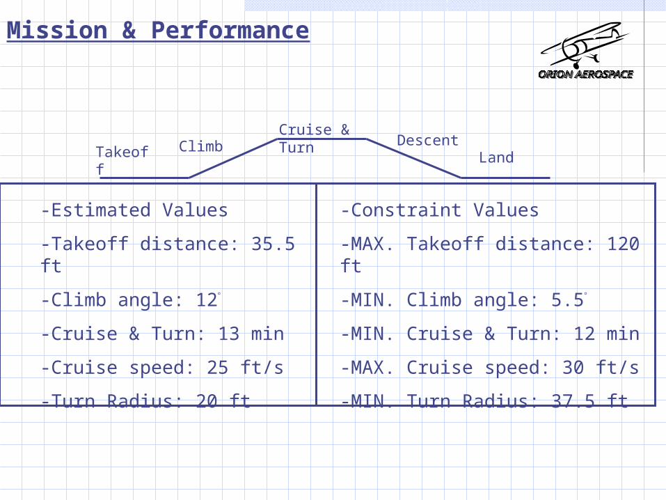
Mission & Performance
Takeoff ClimbCruise & Turn Descent
Land
-Estimated Values
-Takeoff distance: 35.5 ft
-Climb angle: 12
-Cruise & Turn: 13 min
-Cruise speed: 25 ft/s
-Turn Radius: 20 ft
-Constraint Values
-MAX. Takeoff distance: 120 ft
-MIN. Climb angle: 5.5
-MIN. Cruise & Turn: 12 min
-MAX. Cruise speed: 30 ft/s
-MIN. Turn Radius: 37.5 ft
M&P
-Text
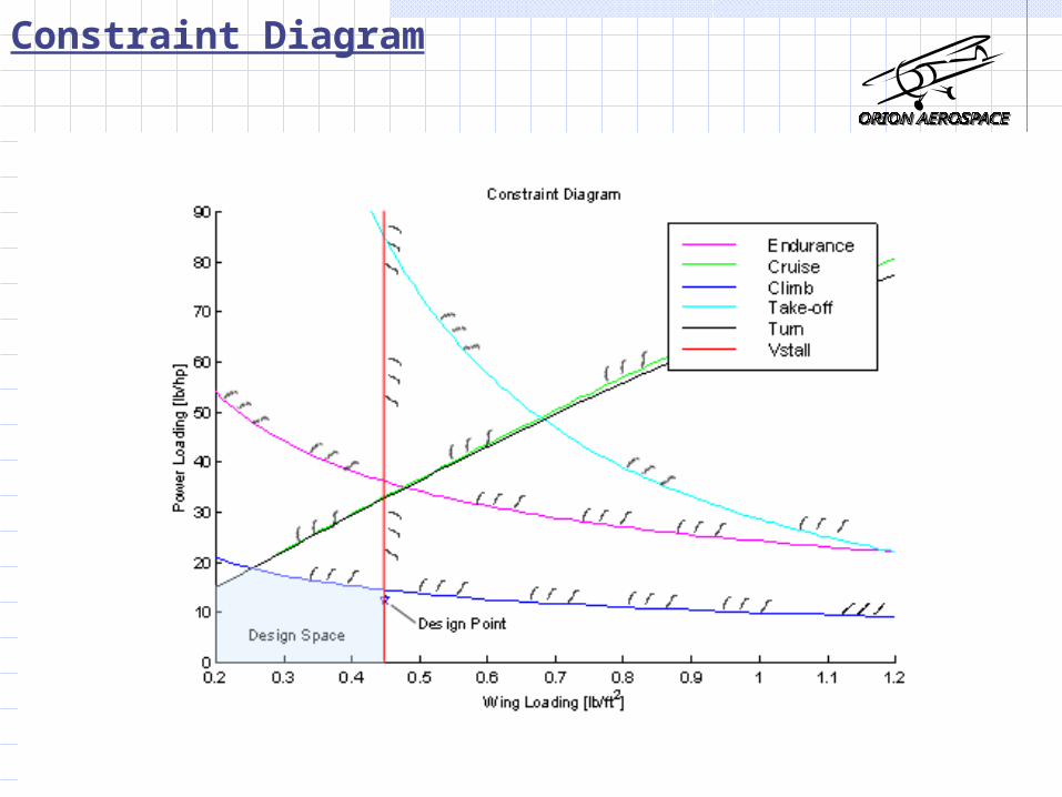
Constraint Diagram

Concept Description
----------------------------------------------------------------------------------------------------
-Square fuselage
-Rectangular wings
-Conventional swept tail
-Taildragger landing gear

3 View of SID5
-DIMENSIONS IN FEET

Aircraft Dimensions
Wing span (b) 6.6 ft
Chord 1.5 ft
Fuselage length 5.9 ft
Span h-tail 3.2 ft
Root chord h-tail
1.3 ft
Tip chord h-tail 0.8 ft
L.E. sweep h-tail 18.4
Horizontal tail area
3.3 ft2
¼ chord sweep h-tail
14.0
Span v-tail 1.3 ft
Root chord V-tail 1.3 ft
Tip chord V-tail 0.8 ft
L.E. sweep V-tail 21.0
¼ chord sweep v-tail 10.9
Vertical tail area 1.3 ft2
Total wetted area 61.2 ft2
Incidence wing 3
Incidence h-tail 0

Aerodynamics
-Selection of Airfoil for Wing
-Selection of Horizontal and Vertical Tail
-Lift Curve
-Drag Polar
-Lift to Drag Ratio vs Angle of Attack
-CMARC Analysis

Aerodynamics
CL 3.93 rad-1
CLwing 4.10 rad-1
CLo .5242
Cm -.4235 rad-1
Cmo 0.50
CDo .0427
Velocity
Re
Stall 20 ft/s 186279
Cruise
25 ft/s 232849
Max 30 ft/s 279419

-Airfoil Selection: Selig-Donavan 7062
-Low Reynolds Number, Slow Speed Flight
-Experimental Data/ Xfoil Analysis
-CL vs Alpha Curve, Drag Polar
-Ease of Construction
-Horizontal and Vertical Tail: Flat Plate Assumption
Aerodynamics

Aerodynamics
Method CL-max
Warner 1.25
Roskam 1.48
Average
1.37
2-D 1.53

Aerodynamics
Phase Angle of Attack CL
Climb 4.0 .75
Cruise 3.0 .70
Turn 5.2 .84
Stall 9.0 1.3
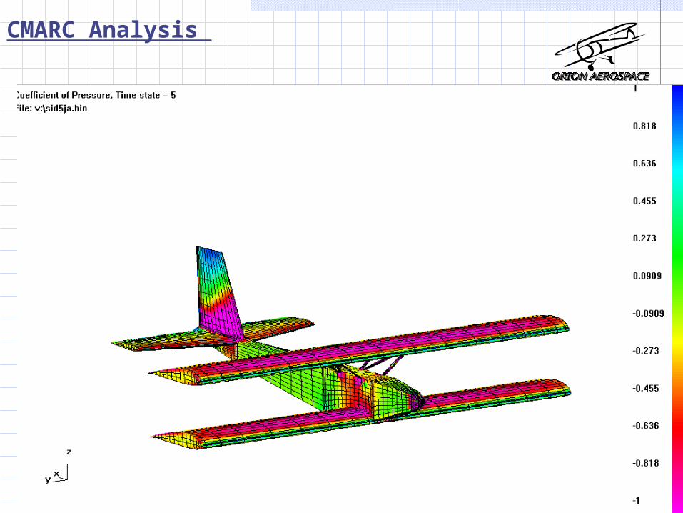
CMARC Analysis

Stability and Control Feedback Loop Description Gain Selection and Description Static Margin, CG, and Aerodynamic Center Control Surface and Tail Sizing Horizontal and Vertical Tail Size Verification Trim Diagram Pertinent Static Stability Derivatives and
Comparison

Loop Closure Description
TX
RX ServoAircraft
Pitch Rate Gyro
)(
)(
s
sq
e
)(
)(
sq
sqm
rk
Pilot
+/ - ?
e q
mq
+
Servo converts voltageto elevator deflection
Pilot inputs elevator command
Sign of feedback gain is chosento stabilize or destabilizethe mode
Rate feedback in the pitch axis Vary the stability of the short period mode
Block Diagram
Real Axis
Imag
inar
y A
xis
Nyquist Diagrams
-1 -0.8 -0.6 -0.4 -0.2 0 0.2 0.4-0.8
-0.6
-0.4
-0.2
0
0.2
0.4
0.6From: U(1)
To:
Y(1
)
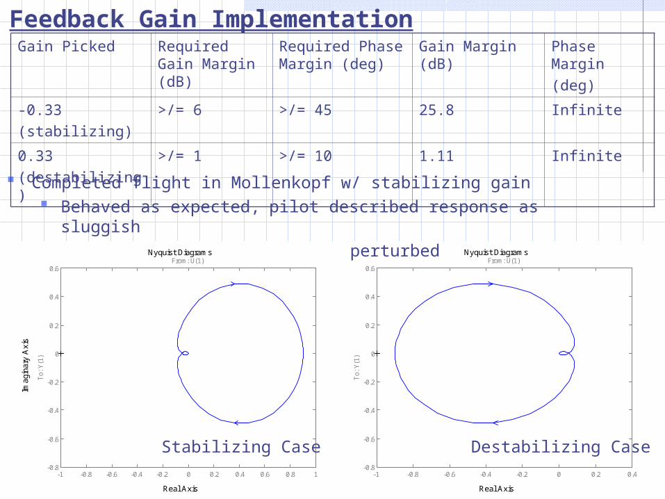
Feedback Gain Implementation
Completed flight in Mollenkopf w/ stabilizing gain Behaved as expected, pilot described response as sluggish Damped out oscillations when perturbed
Gain Picked Required Gain Margin (dB)
Required Phase Margin (deg)
Gain Margin (dB)
Phase Margin(deg)
-0.33(stabilizing)
>/= 6 >/= 45 25.8 Infinite
0.33(destabilizing)
>/= 1 >/= 10 1.11 Infinite
Real Axis
Imag
inar
y A
xis
Nyquist Diagrams
-1 -0.8 -0.6 -0.4 -0.2 0 0.2 0.4 0.6 0.8 1-0.8
-0.6
-0.4
-0.2
0
0.2
0.4
0.6From: U(1)
To:
Y(1
)
Stabilizing Case Destabilizing Case

Static Margin, CG, and Aerodynamic Center
XLE
XCG
XNP
XACHT
Distances in ft
• Static Margin Desired is 10%, puts CG at the 27% chord location• Past 451 final reports agree that 10-15% is an
agreeable range for model aircraft• Pick toward lower end of range to help with
trimming• Pick desired Static Margin and place internal
equipment to obtain the CG that gives this Static Margin

Sizing of Control Surfaces And Tails
• Historical Methods (as described in Raymer’s Aircraft Design: A Conceptual Approach)• Control Surfaces
• Guidelines• Ailerons: 15-25% chord and 50–90%
span• Elevators: 25–50% chord and ~90%
span• Rudders: 25–50% chord and ~90%
span• Selected:
• Ailerons: 15% chord and 90% span• Elevators: 40% chord and 95% span• Rudder: 40% chord and full span
• Tails• Sized using the Tail Volume coefficient
method• Horizontal Tail Volume Coefficient =
0.45• Vertical Tail Volume Coefficient = 0.04
• Coefficients based on old 451 Air designs
V-tail
H-tail
Span(ft) 1.3 3.2
AvgChord(ft)
1.0 1.1
Aspect Ratio
1.30 3.00
Taper Ratio 0.6 0.6
LE Sweep (deg)
21.0 18.4
Dihedral (deg)
0.0 0.0
Planform Area (ft2)
1.3 3.3

Analysis Of Tails
-Horizontal Tail
2.5 2.75 3 3.25 3.5 3.75 4 4.25 4.5 4.75 50.5
1
1.5
2
2.5
3
3.5
4Longitudinal X-Plot
Horizontal Tail Area [ft 2 ]
Dis
tanc
e / W
ing
Cho
rd
Lreq
Lmax po s sXc g
Xnp Design Point (3.3 ft^2)

-Vertical Tail
-“Weathercock” Stability Criterion
Analysis Of Tails
0.5 0.75 1 1.25 1.5 1.75 2 2.25 2.50
0.05
0.1
0.15
0.2
0.25
Cn
bet a [
rad
-1]
Vertical Tail Area [ft 2 ]
Lateral X-Plot
1057.0 radCn (Dr. Roskam’s Airplane Design Series)
Constraint Point
Design Point (1.3 ft^2)
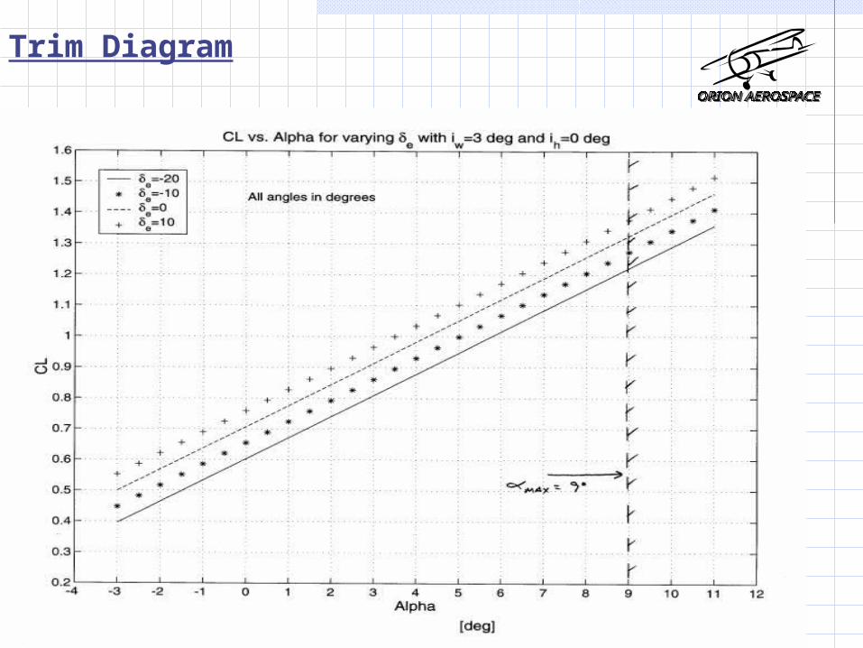
Trim Diagram
-Text

Trim Diagram

Static Stability Derivative Comparison
SID-5 Cessna172
MPX5
-0.40 -0.89 -1.13
0.12 0.07 0.16
-0.81 -1.28 -1.15
-0.08 -0.07 -0.11
mC
nC
emC
rnC
All unitsare rad-1
Note: The MPX5 is a model aircraft designed by Mark Petersfor his thesis, “Development of a Light Unmanned Aircraft for the Determination of Flying Qualities Requirements”, May 1996.

Structures Overview
-Basic layout of the wings
-Structures matlab code
-Material properties
-Equipment layout
-Weight breakdown
-Landing gear analysis

Basic Layout of Wing
Spar
-located at the 1/4 chord
Sparcaps
-spruce
-1/8” x 1/8” x 6.6’
Shearweb
-balsa
-1.5” x 1/16” x 6.6’
Ribs
-balsa
-spaced every 3 inches from tip
-include lightening holes
Added balsa at leading and trailing edge

Geometric Layout of rib & wing
Typical rib section
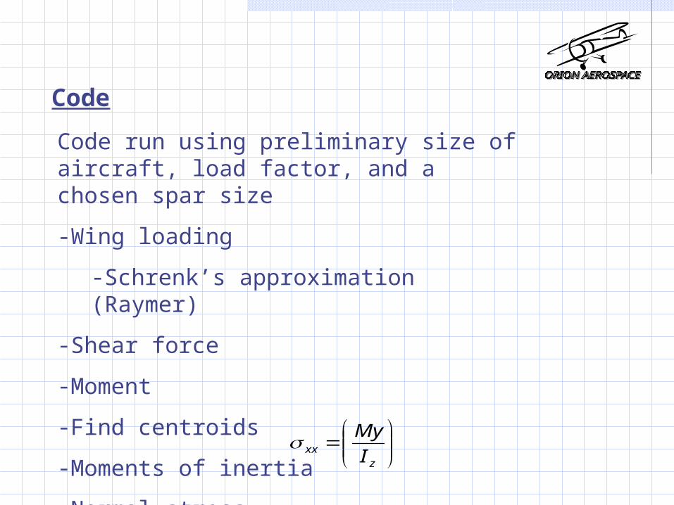
Code
Code run using preliminary size of aircraft, load factor, and a chosen spar size
-Wing loading
-Schrenk’s approximation (Raymer)
-Shear force
-Moment
-Find centroids
-Moments of inertia
-Normal stress
zxx I
My

WING LOADING Trapezoidal approximation
Elliptical approximation
1
21)0()(
b
yqyq
b
wq
75.3*)0(
2^2
1*
4)(
b
y
pib
Syq

SHEAR FORCE

MOMENT

Normal STRESS

Material Properties
Material
Young's Modulus (ksi)
Density (lbf/ft 3̂)
Stress (yield) (psi)
Balsa 625 11 1725Plywood 800 37 4000Spruce 1500 34 8600Monokote (oz/sqin) 0.0021Epoxy (oz/sqin) 0.007CA glue (oz/joint) 0.0068
Table taken from Spring ’99 AAE 451 report (Team WTA)
-Normal Stress (at spar caps) = 2750psi

Internal equipment layout
Equipment Volume(in3)
Gear box 3 x 1.5 x 1
Motor 2.25 x 1.5
Speed Controller 1.5 x 1.25 x 1
Receiver 1.75 x 1.25 x 0.75
Gyro 1.5 x 1.25 x 1.25
Data Recorder 1.75 x 2.25 x 3.25
Battery(18) 2 x 1 x 1
Servo 1.5 x 1.25 x 0.75
Interface 1.25 x 3.5 x 5.75

Predicted Weight Breakdown
Wing 42.0 (oz)
Tail 9.5 (oz)
Fuselage 11.0 (oz)
Misc 9.8(oz)
Receiver 1.0(oz)
Speed controller 3.0(oz)
Gyro 3.5(oz)
Tattletail8 15.0(oz)
Motor 7.5(oz)
Gearbox 1.5(oz)
Propeller 1.0(oz)
Servo(4) 2.0(oz)
Cell weight(18) 2.8(oz)Total Weight SID5 Total Weight SID5 = 163.2 (oz), = 163.2 (oz), 10.2(lbs)10.2(lbs)

Landing Gear
-Conventional taildragger landing gear
Method for sizing and placement of landing gear Figure 11.4 Raymer
-Lateral separation angle of 37.7
-Located
1.2’ from nose
0.6” in front of the leading edge

Propulsion
•Constraint Values for Propulsion Design
-Motor Selection
-Propeller Selection
-Speed Controller Selection
-Gearbox Selection
-Battery Sizing & Energy Balance
-Results from the Flight Tests
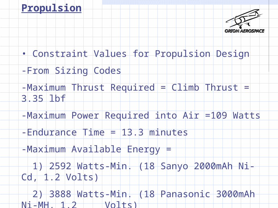
Propulsion
• Constraint Values for Propulsion Design
-From Sizing Codes
-Maximum Thrust Required = Climb Thrust = 3.35 lbf
-Maximum Power Required into Air =109 Watts
-Endurance Time = 13.3 minutes
-Maximum Available Energy =
1) 2592 Watts-Min. (18 Sanyo 2000mAh Ni-Cd, 1.2 Volts)
2) 3888 Watts-Min. (18 Panasonic 3000mAh Ni-MH, 1.2 Volts)

Propulsion
• Motor Selection
-Tool : Modified Motor Code provided by Prof. Andrisani
-Criteria : High Efficiency, High Power at Low Current
Efficiency at different Battery Currents
75
80
85
90
95
AstroCO25 Aveox 1415/1.5 Aveox 1415/2 Maxcim N32-13Y Maxcim N32-13D
Motors
Eff
icie
ncy
(%)
At 17 Amps
At 23 Amps
At 30 Amps
Power Output at diffent Battery currents
0
200
400
600
800
AstroCO25 Aveox 1415/1.5 Aveox 1415/2 Maxcim N32-13Y
Maxcim N32-13D
Motors
Po
wer
ou
tpu
t (w
atts
) At 17 Amps
At 23 Amps
At 30 Amps

PropulsionEfficiency of 8" pitch Propeller
0
0.2
0.4
0.6
13 14 15 16 18 20 22 24
Diameter
Eff
icie
nc
y
Gear Ratio =3.53
Gear Ratio =3.75
Gear Ratio =4
Maximum Power Ouptut at Different Voltage
0
200
400
600
800
AstroCO25 Aveox1415/1.5
Aveox1415/2
MaxcimN32-13Y
MaxcimN32-13D
Motors
Po
we
r (
Wa
tts
)
At 19.2 Volts
At 21.6 Volts
Maximum Efficiency of Motor at Different Voltage
0.740.760.780.8
0.820.840.860.880.9
0.92
AstroCO25 Aveox1415/1.5
Aveox1415/2
MaxcimN32-13Y
MaxcimN32-13D
Motors
Effic
ien
cy
At 19.2 Volts
At 21.6 Volts

Propulsion• Propeller Selection
-Tool : Modified Gold Code provided by Prof. Andrisani
-Criteria : High Efficiency, Low Power Usage, High Thrust at 25 ft/sec.Power used to run 8" pitch Propeller
00.5
11.5
22.5
13 14 15 16 18 20 22 24
Diameter (inch)
Po
we
r (k
wa
tt)
Gear ratio=3.53
Gear ratio=3.75
Gear ratio=3.53
Thrust produced by Propeller at 8" pitch
0
10
20
30
13 14 15 16 18 20 22 24
Diameter (inch)
TR
hru
st(
lbf)
Gear Ratio=3.53
Gear ratio=3.75
Gear ratio =4

Propulsion
•Gearbox and Speed Controller Selection
-Tool : Modified Gold Code provided by Prof. Andrisani
-Criteria : Minimum Power dissipated by Controller, High Efficiency, Low RPM
Speed Controller GearboxModel Maxµ35B-21 Maxµ35B-25NB Gear ratio RPM Power input Power output
Efficiency (%) 99.3 99.06 3.53 8292.30 333.95 317.25Resistance 0.009 0.012 3.75 7805.80 333.95 317.25
Power output (W) 367.2 367.2 4 7318.00 333.95 317.25Power input(W) 369.80 370.67
Power Dissipated (Watts) 2.60 3.47
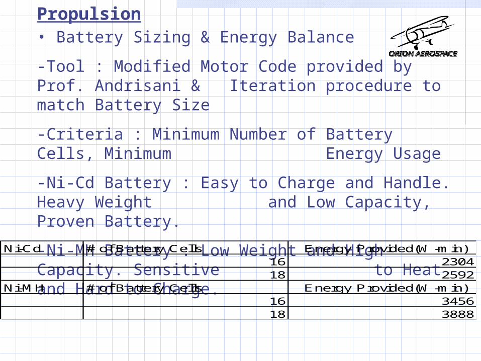
Propulsion• Battery Sizing & Energy Balance
-Tool : Modified Motor Code provided by Prof. Andrisani & Iteration procedure to match Battery Size
-Criteria : Minimum Number of Battery Cells, Minimum Energy Usage
-Ni-Cd Battery : Easy to Charge and Handle. Heavy Weight and Low Capacity, Proven Battery.
-Ni-MH Battery : Low Weight and High Capacity. Sensitive to Heat and Hard to Charge.
Ni-Cd # of Battery Cells Energy Provided(W-min)16 230418 2592
Ni-MH # of Battery Cells Energy Provided(W-min)16 345618 3888
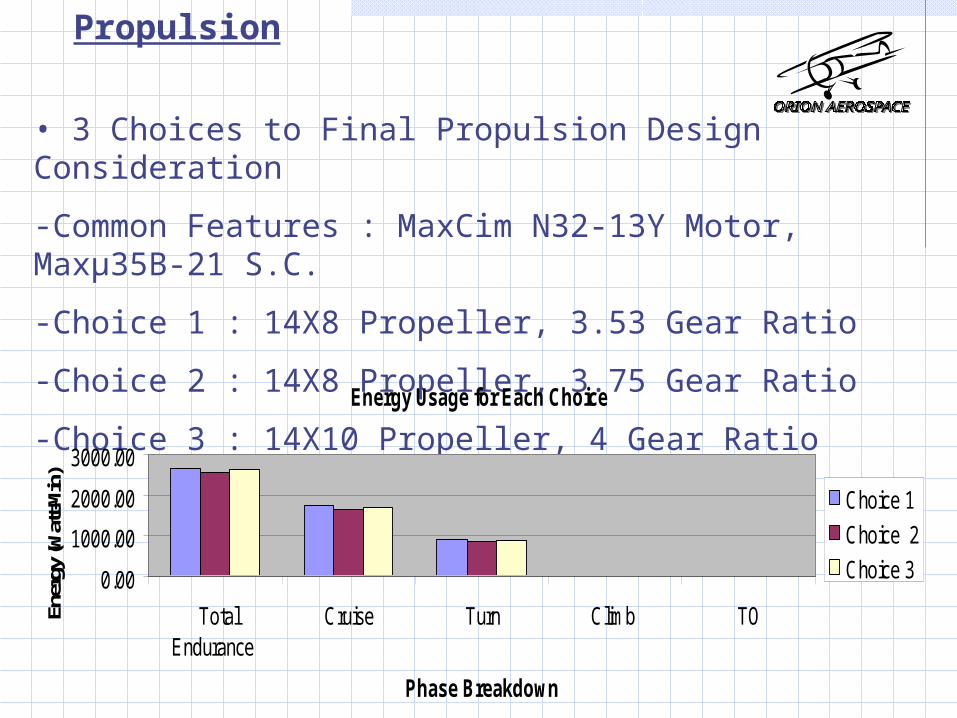
Propulsion
• 3 Choices to Final Propulsion Design Consideration
-Common Features : MaxCim N32-13Y Motor, Maxµ35B-21 S.C.
-Choice 1 : 14X8 Propeller, 3.53 Gear Ratio
-Choice 2 : 14X8 Propeller, 3.75 Gear Ratio
-Choice 3 : 14X10 Propeller, 4 Gear RatioEnergy Usage for Each Choice
0.00
1000.00
2000.00
3000.00
TotalEndurance
Cruise Turn Climb TO
Phase Breakdown
Ener
gy (W
att-M
in)
Choice 1
Choice 2
Choice 3

Propulsion•Final Propulsion Design Selection
-Choice 1 : MaxCim N32-13Y Motor, Maxµ35B-21 S.C, 14X8 Propeller, 3.53 Gear Ratio, 18 Battery Cells
-Overall Efficiency : 38.55%Required Thrust Throttle Setting Estimated Throttle Setting
Cruise 2.14 54.4 50%Turn 2.56 65.1 60%
Climb 3.35 85.2 80%
Choice 1 Prop. Motor S.C. GB14X8 Maxcim N32-13Y Maxµ35B-21 3.53
Efficiecy (%) 44.93 90.94 99.30 95Power required by Prop. Watts 296.70 MAX. Thrust required lbf 3.35Battery Power needed Watts 345.85 Thrust provided by Prop. lbf 3.93Battery Power Provided Watts 369.81 MIN.Energy required W-Min 2662.71Power provided into air Watts 133.31 EST. MIN. Energy required W-Min 2452.71MIN. Power into air req. Watts 109.00 MAX.Energy provided W-Min 2592.00MIN. Endurance Time Min 12.00 Total Endurance time Min 13.29
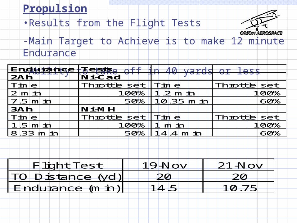
Propulsion•Results from the Flight Tests
-Main Target to Achieve is to make 12 minute Endurance
-Ability to take off in 40 yards or lessEndurance Tests2Ah Ni-CadTime Throttle set Time Throttle set2 min 100% 1.2 min 100%7.5 min 50% 10.35 min 60%3Ah Ni-MHTime Throttle set Time Throttle set1.5 min 100% 1 min 100%8.33 min 50% 14.4 min 60%
Flight Test 19-Nov 21-NovTO Distance (yd) 20 20Endurance (min) 14.5 10.75

Mission & Performance
-Phase Time Breakdown, Energy & Power Requirement
Time (Min) Energy Required (W-min)Total Endurance 13.29 2548.22
Cruise 9.17 1651.42Turn 4.01 863.85
Climb 0.07 18.85TO 0.05 14.10
Speed (ft/sec) Thrust(lbf) Batt. Power (W)Turn Speed 25 2.56 220.89TO Speed 24 3.35 289.05Climb Speed 24 3.35 289.05Cruise Speed 25 2.14 184.65

Cost Analysis
-Wing Test Materials ~ $90
-SID5 Materials ~ $259.95
-SID5 Electronics ~ $1125
-Man Hours (estimate) ~ 2650
-Labor ($75/hour) ~ $198,750
-Total ~ $200,125

Price Breakdown of SID5
LXK196 1/4-20 WING BOLT (4) 1 1.25 1.25 4/4 1.25GPMQ4258 6-32 (4) STRUT FITTING 6 2.29 13.74 24/24 13.74
LXJ041 SOCKHD SCRW 6-32X1 1/2 (4) 6 1.4 8.4 24/24 8.40GPMQ3130 6X1/2 (8) SHEET METAL SCREW (8) 3 1.35 4.05 24/24 4.05K+SR2803 1/2 STREAMLINE ALUM TUBE (4) 1 11.99 11.99 2/4 6.00GPMQ3750 2-56X12 PUSHROD (6) 2 2.19 4.38 6/12 2.19
GPMQ3791 2-56 THREADED CLEVIS (12) 1 5.19 5.19 8/12 3.46
GPMQ3860 SWIVEL CLEVIS (2) 2 0.99 1.98 4/4 1.98
GPMQ3901 CONTROL HORN (2) 3 0.8 2.4 6/6 2.40LXH958 KLETT LANDING GEAR .40-.60 1 20.99 20.99 1/1 20.99
DAVQ5310 2 1/4 WHEELS (2) 1 3.89 3.89 2/2 3.89LXD850 TAILWHEEL BRACKET 1 1.99 1.99 1/1 1.99LXK159 3/4 TAILWHEEL 1 1.39 1.39 1/1 1.39LXJ212 INSTANT JET 2OZ 2 9.99 19.98 2/2 19.98LXJ215 SLOW JET 1OZ 1 6.19 6.19 1/1 6.19
TOPQ1205 ALUMINUM MONOKOTE 1 54.99 54.99 1/1 54.99TOPQ1204 ALUMINUM MONOKOTE 2 13.99 27.98 2/2 27.98TOPQ0402 METALLIC BLUE MONOKOTE 2 13.99 27.98 2/2 27.98
JR XP8103 Radio 1 500.00 500.00 1/1 500.00MaxCim Motor System 1 400.00 400.00 1/1 400.00
Battery Pack 2 112.50 225.00 1/1 225.00TOTAL 1411.86 USED PARTS 1384.95
KIT PRICE 122.83

Construction-AutoCAD drawings: actual size-Component templates created-Wing construction
-ribs: balsa-spar caps: spruce-shear web: balsa-leading edge: balsa -aileron construction: balsa (w/ribs)-monokote-struts

Construction-Vertical and Horizontal Tail Construction
-balsa truss structure-built off AutoCAD drawings-monokote
-Fuselage-balsa truss structure-constructed sides first-built top by holding sides and gluing pieces -sheet bottom to support components-velcro to inside for electronic components-monokote added

Construction-Endplates
-balsa truss structure-monokote-plastic screws to attach to fuselage
-Landing Gear-main landing gear-tail gear
-Motor mount-Control Surface attachments
-ailerons-rudder-elevator

Construction
Component Weight
Payload 1 lb
Endplates 0.27 lb
Fuselage, motor, controller, tail, landing gear, propeller, 2 servos, receiver, gyro
3.78 lb
Upper wing, struts, control rods 1.30 lb
Lower wing, 2 servos, wires 1.53 lb
2000 mAh NiCd 3.38 lb
3000 mAh NiMH 2.17 lb Total Weight: w/ NiCd: 11.26 lb
w/ NiMH: 10.05 lb

Actual Performance
Takeoff ClimbCruise & Turn Descent
Land
-Estimated Values
-Takeoff distance: 35.5 ft
-Climb angle: 12
-Cruise & Turn: 13 min
-Cruise speed: 25 ft/s
-Turn Radius: 20 ft
-Actual Values
-Takeoff distance: 24 ft
-Climb angle: ~20
-Cruise & Turn: ~12 min
-Cruise speed: ~27 ft/s
-Turn Radius: 12 ft

Flight Results: Saturday- Flight 1Pilot: Dave HenadyATM. Press.: 30.22 mm Hg Temp: 30 FLocation: Delphi AirportMission: Attempted First FlightComments: ~extremely windy ~had problem keeping airplane from blowing away ~sustained minor damage from being blown into parked car ~need to add down trim to plane-Pilot ~initially was too cold for motor to function, had to be brought in and
warmed up ~plane was predictable and handled well-PilotDuration: 3 minutesTake off Distance: ~plane basically hopped into the airLanding: ~no major problemsBattery Utilized: NiCdDamage Report: ~cracked ribRepair Time: ~minor
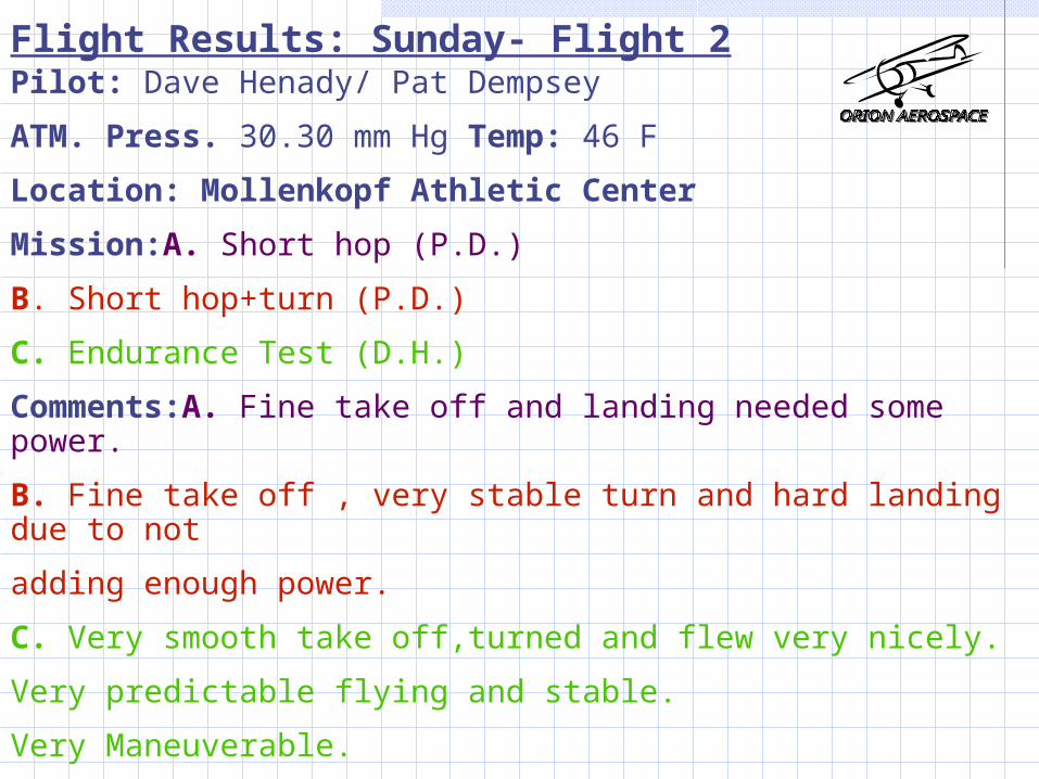
Flight Results: Sunday- Flight 2Pilot: Dave Henady/ Pat Dempsey
ATM. Press. 30.30 mm Hg Temp: 46 F
Location: Mollenkopf Athletic Center
Mission:A. Short hop (P.D.)
B. Short hop+turn (P.D.)
C. Endurance Test (D.H.)
Comments:A. Fine take off and landing needed some power.
B. Fine take off , very stable turn and hard landing due to not
adding enough power.
C. Very smooth take off,turned and flew very nicely.
Very predictable flying and stable.
Very Maneuverable.
A lot of power.

Flight Results: Sunday- Flight 2Duration: A: less than 15 sec.
B: About 20 sec.
C:Appr. 14 min. 30 sec.
Flight Speed: A: 25 ft/s
B: 25 ft/s
C: 27~ 30 ft/s
Take off Distance: A: 15 yards
B: 15 yards
C: 20 yards
Landing: A: 10 yards
B: 2 yards
C: 40~50 yards
Battery Utilized: NiMH

Damage Report: A: No damage.
B: Separated firewall of motor.
C: No damage.
Repair Time: A: None
B: 5 min.
C: None
Flight Results: Sunday- Flight 2

Flight Results: Sunday- Flight 3Pilot: Dave HenadyATM. Press.: 30.30 mm Hg Temp: 46 FLocation Mollenkopf Athletic FacilityMission: Flap Test during indoor flightComments: ~Flight started out well~Adding flaps on landing is not the best idea~Plane was stopped by student to keep from hitting wall~adding flaps pitched plane up, and had to add more down elevator~Group heart attack occurred shortly after crash~it was demonstrated that feedback gain can be usedDuration: 5 minutesTake off Distance: 20 yardsLanding: ~Plane was caught in ground effect. Would not land. ~Touched down late and then hit studentBattery Utilized: NiCd

Flight Results: Sunday- Flight 3
Damage Report: ~crushed leading edge on left side of bottom wing
~crushed leading edge on majority of upper wing~about 15 broken ribs~broken elevator~major damage to group moraleRepair Time: ~substantial, about 90 man hours
Flight Results: Tuesday –Flight 4
Pilot: Dave HenadyATM. Press.: 30.33 mm Hg Temp: 46 FLocation Mollenkopf Athletic FacilityMission: demonstrate a/c flight both w and w/o feedback
gainComments: ~Very predictable~gyro dampened out oscillations~made the controls more sluggishDuration: 5 minutesTake off Distance: 15 yardsLanding: 30 yards. No problemsBattery Utilized: NiCd
Damage Report: Happily None to ReportRepair Time: Nonexistent

Flight Results: Tuesday- Flight 5
Pilot: Sean HenadyATM. Press.: 30.33 mm Hg Temp: 46 FLocation Mollenkopf Athletic FacilityMission: perform the a/c mission of 12 minutesComments: ~did not make 12 minutes because performed a
lot of maneuvers~flew nicely~did four circles hands off ~pilot enjoyed flying this planeDuration: 10:43 minutesTake off Distance: 20 yardsLanding: 30 yards. No problemsBattery Utilized: NiMHDamage Report: Happily None to ReportRepair Time: Nonexistent
Flight Results: Tuesday- Flight 6Pilot: Sean Henady
ATM. Press.: 30.33 mmHg Temp: TEMP:46F
Location Mollenkopf Athletic Facility
Mission: High Performance Test
Comments: Short take off with full throttle setting.
Tight turn with 6 yard radius.
Demonstrated nice roll rate.
Successful stall turns.
Tested the minimal stall speed with power on and off.
With power off stall speed was less than approximately. 20 ft/s.
With power on stall speed was less than approximately.15 ft/s.
Achieved maximum speed in Mollenkopf was approximately.100 ft/s.

Flight Results: Tuesday- Flight 6
Duration: Approximately 8 min.Take off Distance: 8 yardsFlight Speed: Between 10 and 58 mph.Landing: 10 yardsBattery Utilized: NiCd.Damage Report: No Damage.Repair Time: Nonexistent

conclusion
-aircraft completed mission
-aircraft was more maneuverable than designed
-aircraft cost $60 more than predicted
-aircraft weight was similar
-aircraft was able to perform with and without gain
-took 2700 hours to build
-if future models were built using a machine to cut out parts would be explored.
-materials other than balsa may be explored if indoor flight was continued. (not the most robust)

Questions?