Path Tracking Laws and Implementation of a Vision-Based ...
12
Path Tracking Laws and Implementation of a Vision -Based Wheeled Mobile Robot YING-SHING SHIAO, JUI-LIANG YANG, DING-TSAIR SU Department of Electrical Engineering National Chang-hua University of Education Chang-hua 520 Taiwan REPUBLIC OF CHINA.(TAIWAN) [email protected], [email protected], [email protected] http://www.ncue.edu.tw Abstract: - This paper has studied techniques for building system configuration, control architecture and implementation of a vision-based wheeled mobile robot. The completed WMR has been built with the dead-reckoning method so as to determine the vehicle ’s velocity and posture by the numerical differentiation/integration over short travelling. The developed PID controllers show good transient performances, that is, velocity of right and left wheels can track the commands quickly and correctly. Moreover, the path tracking control laws have been also executed in the DSP-based controller in the WMR. The image-recognized system can obtain motion information 15 [frames/sec] by using H -S model, which is one of the well-known color detection methods. The better performance a vision system has, the more successful the control laws design. The WMR obtains its posture from the dead- reckoning device together with the vision system. Finally, we integrate these subsystems and complete the operators of the whole system. This complementing wheeled mobile robot system can be thought of as a platform for testing various tracking control laws and signal filtering method. To solve the problem of position/orientation tracking control of the WMR, two kinematical optimal nonlinear predictive control laws are developed to manipulate the vehicle to asymptotically follow the desired trajecto ries. A Kalman filtering scheme is used to reduce the bad effect of the imagine nose, thereby improving the accuracy of pose estimation. The experimental system is composed of a wireless RS232 modem, a DSP -based controller for the wheeled mobile robot and a vision system with a host computer. A computation -effective and high- performance DSP-based controller is constructed for executing the developed sophisticated path tracking laws. Simulation and experimental results are included to illustrate the feasibil ity and effectiveness of the proposed control laws. Key-Words: - Predictive control; Mobile robot; Path tracking; Nonlinear characteristics , Kalman filtering 1 Introduction This paper is devoted to developing methodologies and techniques for control architecture design, path tracking laws and implementation of a vision-based wheeled mobile robot (WMR). This study has been mainly excited by a wide variety of practical mobile robots applications due to their ability to work in various domains. WMRs have already gained widespread applications, such as planetary exploration, materials transportation, military tasks, manufacturing servicing, hazardous environment and mine excavation. To achieve the aforementioned tasks, the WMR requires sensing of the environments, intelligent trajectory planning, navigation and path tracking control. This desired autonomous or intelligent behavior has motivated an intensive research over the past decades. To achieve path-tracking control for the WMRs, many sophisticated control approaches have been investigated by several researchers. The existing tracking control methods for the WMR can be classified into five categories: (i.) sliding mode [1]; (ii.) nonlinear control [2-3]; (iii.) fuzzy control [4]; (iv.) neural network control [5]; and (v.) adaptive backstepping control [6]. In 2007, Qiuling et al. used sliding mode control for tracking control, which is complicated and computationally expensive. The generated velocity command with respect to time is not a smooth curve in [1]. Lei et al. introduced the fuzzy tracking control approaches [ 4] in 2006. But it is very difficult to formulate the fuzzy rules, which are usually obtained from the trial-and-error procedure. In 2006, the computational expensive neural network was adopted by Heinen et al. [5]. The algorithm requires on-line learning in order to make the robot perform WSEAS TRANSACTIONS on CIRCUITS and SYSTEMS Ying-Shing Shiao, Jui-Liang Yang, Ding-Tsair Su ISSN: 1109-2734 965 Issue 12, Volume 7, December 2008
Transcript of Path Tracking Laws and Implementation of a Vision-Based ...

Path Tracking Laws and Implementation of a Vision -Based WheeledMobile Robot
YING-SHING SHIAO, JUI-LIANG YANG, DING-TSAIR SUDepartment of Electrical Engineering
National Chang-hua University of EducationChang-hua 520 Taiwan
REPUBLIC OF CHINA.(TAIWAN)[email protected], [email protected], [email protected]
http://www.ncue.edu.tw
Abstract: - This paper has studied techniques for building system configuration, control architectureand implementation of a vision-based wheeled mobile robot. The completed WMR has been built withthe dead-reckoning method so as to determine the vehicle’s velocity and posture by the numericaldifferentiation/integration over short travelling. The developed PID controllers show good transientperformances, that is, velocity of right and left wheels can track the commands quickly and correctly.Moreover, the path tracking control laws have been also executed in the DSP-based controller in theWMR. The image-recognized system can obtain motion information 15 [frames/sec] by using H -Smodel, which is one of the well -known color detection methods. The better performance a visionsystem has, the more successful the control laws design. The WMR obtains its posture from the dead-reckoning device together with the vision system. Finally, we integrate these subsystems and completethe operators of the whole system. This complementing wheeled mobile robot system can be thoughtof as a platform for testing various tracking con trol laws and signal filtering method. To solve theproblem of position/orientation tracking control of the WMR, two kinematical optimal nonlinear predictivecontrol laws are developed to manipulate the vehicle to asymptotically follow the desired trajecto ries. AKalman filtering scheme is used to reduce the bad effect of the imagine nose, thereby improving the accuracyof pose estimation. The experimental system is composed of a wireless RS232 modem, a DSP -based controllerfor the wheeled mobile robot and a vision system with a host computer. A computation -effective and high-performance DSP-based controller is constructed for executing the developed sophisticated path tracking laws.Simulation and experimental results are included to illustrate the feasibil ity and effectiveness of the proposedcontrol laws.
Key-Words: - Predictive control; Mobile robot; Path tracking; Nonlinear characteristics, Kalman filtering
1 IntroductionThis paper is devoted to developing
methodologies and techniques for controlarchitecture design, path tracking laws andimplementation of a vision-based wheeled mobilerobot (WMR). This study has been mainly excitedby a wide variety of practical mobile robotsapplications due to their ability to work in variousdomains. WMRs have already gained widespreadapplications, such as planetary exploration,materials transportation, military tasks,manufacturing servicing, hazardous environmentand mine excavation. To achieve theaforementioned tasks, the WMR requires sensing ofthe environments, intelligent trajectory planning,navigation and path tracking control. This desiredautonomous or intelligent behavior has motivated anintensive research over the past decades.
To achieve path-tracking control for the WMRs,many sophisticated control approaches have beeninvestigated by several researchers. The existingtracking control methods for the WMR can beclassified into five categories: (i.) sliding mode [1];(ii.) nonlinear control [2-3]; (iii.) fuzzy control [4];(iv.) neural network control [5]; and (v.) adaptivebackstepping control [6]. In 2007, Qiuling et al.used sliding mode control for tracking control,which is complicated and computationallyexpensive. The generated velocity command withrespect to time is not a smooth curve in [1]. Lei et al.introduced the fuzzy tracking control approaches [ 4]in 2006. But it is very difficult to formulate thefuzzy rules, which are usually obtained from thetrial-and-error procedure. In 2006, thecomputational expensive neural network wasadopted by Heinen et al. [5]. The algorithm requireson-line learning in order to make the robot perform
WSEAS TRANSACTIONS on CIRCUITS and SYSTEMS Ying-Shing Shiao, Jui-Liang Yang, Ding-Tsair Su
ISSN: 1109-2734 965 Issue 12, Volume 7, December 2008

properly. Design of the path following controller forgyrobot, a gyroscopically stabilized single-wheeledrobot, is presented [7].
In this paper, we introduced two optimalnonlinear predictive control approaches [ 8-9] formanipulators. The control laws minimized aquadratic performance index of the state predictedtracking error. The algorithms were shown toimprove tracking accuracy of the manipulators.
In addition, Kalman filter police has beenproposed in [10-11]. In this paper, we extend theKalman filter method to deal with the poseestimation problem of the WMR with corruptedimaging noise.
This paper is organized as follows. Camera -SpaceTracking Control is presented in Section 2, andsection 3 introductions kinematic model andkinematic tracking control design. Section 4 aims atdeveloping two optimal nonlinear predictive controlapproaches. Section 5, an extended Kalmanfiltering scheme is adopted to fil ter out the corruptednoise in the images. In Section 6 simulation andexperimental results are presented. Section 7concludes this paper.
2 Camera-Space Tracking Control2.1 Vision-based Control System
The control objective for the vision -basedtracking problem is to manipulate the WMR tofollow the desired trajectory. This system iscomposed of a ceil-mounted fixed camera whoseoutputs are connected to a host computer, and aWMR with two atop different color, round marks(in Fig.1).
Fig. 1 Camera system configuration
The host computer is used to periodically providethe position and orientation information of the
WMR for tracking the reference trajectory, via thewireless RS232 modem. The operation of such acontrol system can be easily understood from thesystem block diagram shown in Fig.2.
Fig.2 A block diagram of the vision-based controlsystem
The digital DSP-based controller has beendesigned with multi-loop characteristics. Fig.3details the DSP-Based control system with inner Pcurrent control loop, encoder -based PID motorvelocity control and dead-reckoning-based pathtracing control. The very structure of the DSP-basedcontroller is very useful in proving high -performance operation and control for the WMR.
Fig. 3 DSP-based control system
2.2 PID Velocity Controller DesignIn the following design, the wheeled mobile robot
employs the two DC servo motors with two opticalencoders. The digital optical encoder generates 16QEP pulses per revolution, and the motors have themaximum velocity of MAX(w)=482 [rpm].
Fig.4 shows the chassis of the WMR, where thelength of the driving axis between the wheels is
0L 15[cm], and the radius of the wheels i s
0 2.7056[cm]. Hence we can calculate the
maximum linear and angular velocities of the WMR,as below
WSEAS TRANSACTIONS on CIRCUITS and SYSTEMS Ying-Shing Shiao, Jui-Liang Yang, Ding-Tsair Su
ISSN: 1109-2734 966 Issue 12, Volume 7, December 2008

Fig. 4 The chassis of wheeled mobile robot
[cm/s]13.202
L
VVR
[rad/s]368.52/0
L
VV LR (1)
The DSP-based controller demodulates themodem signals sent from the host computer , andobtains the position and orientation of the WMR.After performing the tracking control algorithm,with the sampling period of 20 [ms], the DSP-basedcontroller outputs the following speed commands tothe two driving wheels
22
2 0 L
VR
22
2 0 L
VL
(2)
Therefore, with the speed commands, thevelocities of the right and left wheels of the WMRare regulated by the PID control laws, whosesampling period is 1 [ms].
2.3 Dead-reckoned Posture EstimationThe output signals of the encoder are directly
connected to DSP. Counting the pulse numbers fromthe encoders composes the dead-reckoning device.Thus, we have
264
LL
N 2
64 R
R
N(3)
Rd LL 0rd RR (4)
The ( 0r ) is the mentioned radius of the wheels.
Hence we can know the traveling distances of theright and left wheels, Ld and Rd . The
orientation difference, and the travelingdistance d can be employed to find thesubsequent position and orientation of the vehicle.Thus, we have
2/)(2 0
RLLR ddd
L
dd
)(cos)1()(
)1()(
kdkxkx
kk
)(sin)1()( kdkyky (5)
2.4 Accomplished WMR and Controller ’sCircuitry
Fig. 5 Physical view of the integrated DSP-basedcontrol board
Fig.5 shows the completed DSP-based controlleron a print circuit board (PCB). Fig.6 depicts a recentpicture of the wheeled
Fig. 6 A recent picture of the wheeled mobile robot
2.5 Vision SystemTo achieve quick and smooth motion of the robot,
the vision servoing system plays an important key.Here we use a color CCD-based vision system tolocalize the position and orientation of the WMR.
WSEAS TRANSACTIONS on CIRCUITS and SYSTEMS Ying-Shing Shiao, Jui-Liang Yang, Ding-Tsair Su
ISSN: 1109-2734 967 Issue 12, Volume 7, December 2008

CCDCanera
SoccerField
ImageCaptureCard
HistogramModification
PatternRecongnition
OrientationPostion, andVelocity Data
AnalogGrayLevelImage
DigitalGrayLevelImage
HostComputer
Decision andControl System
Fig.7 The operational procedure of the visionsystem
A camera mounted on the ceiling has a height of3[m] above the robot workspace in order tocontinuously capture the motion images of the robotinto the host computer through the image -capturingcard. Fig 7 shows the operational procedure of thevision system. Before obtaining the positions of thecolor marks, we must be to check and calibrate theimage distortion caused by the lens effect. Twokinds of distortions caused by the lens are illustratedin Fig. 8. Since not all parts of the lens can matchthe ideal pin-hole model, the image magnificationfactors should be compensated according to thedistortion condition.
Fig. 8 Image distortions caused by the lenseffects
From Fig. 8(a), we observe that the distortion typeof the camera in our vision system belongs to thetype of concave distortion. In Fig.9, to calibratesuch a distortion, the following equation cancelingthe effects is expressed by
Fig. 9 Concave distortion effects (a) in the task-space, (b) in the camera-space
rQrPR 2 (6)
where R is the distance in the task -space, r is thedistance in the camera-space, and the Parameters Pand Q are two ratios. By finding out the relationship
Fig. 10 HIS model
between (R1, R2) in the task-space and (r1, r2) inthe camera-space, we obtain the following equationto computer the values of P ad Q,
2
1
22
2
12
1
R
R
rr
rrinv
Q
P(7)
Object recognition in a vision system can beachieved using edge detection or a gray leveldetection method. Here two different color patternsmounted on the top plate of the robot are adopted toestimate the WMR position/orientation. Aside fromthe previous detection approaches, an alternative topattern recognition is a color detection method.There are several color models for image processes,such as RGB, HIS, YUV and so on. The RGBvalues of each pixel in the image can be grabbedutilizing MIL (Matrox Imaging Libraryprogramming) in the vision system. Although thepattern recognition can be completed via the RGBmodel, we choose HIS color model (see Fig. 10) asthe basis of the recognition i n contrast to theunstable behavior of the RGB model in each pixel.
WSEAS TRANSACTIONS on CIRCUITS and SYSTEMS Ying-Shing Shiao, Jui-Liang Yang, Ding-Tsair Su
ISSN: 1109-2734 968 Issue 12, Volume 7, December 2008

The transform function of the RGB model to HISmodel is described as follows:
(8)
2.6 Concluding RemarksThis paper has studied techniques for building
system configuration, control architecture andimplementation of a vision-based wheeled mobilerobot. The completed WMR has been built with thedead-reckoning method so as to determine thevehicle’s velocity and posture by the numericaldifferentiation/integration over short traveling. Thedeveloped PID controllers show good transientperformances, that is, velocity of right and leftwheels can track the commands quickly andcorrectly. Moreover, the path tracking control lawshave been also executed in the DSP-based controllerin the WMR. The image-recognized system canobtain motion information 15 [frames/sec] by usingH-S model, which is one of the well-known colordetection methods. The better performance a visionsystem has, the more successful the control lawsdesign. The WMR obtains its posture from the dead-reckoning device together with the vision system.Finally, we integrate these subsystems and completethe operators of the whole system. Thiscomplementing wheeled mobile robot system can bethought of as a platform for testing various trackingcontrol laws and signal filtering method.
3 Preliminary Background3.1 Kinematic Model
Consider a nonholonomic WMR under theassumption of pure rolling and non -slipping. Itskinematic model is given by
( )q S q u ( 9)
Where 3( ), ( )q t q t are defined by
c cq x y T
c cq x y (10)
( )cx t , ( )cy t and ( )t represent the
position/orientation of the WMR in Fig.11
respectively, the matrix 3 2( )S is defined asfollows
cos 0
( ) sin 0
0 1
S q
(11)
And the velocity vector 2( )u t is denoted by
1 2
TT
lu v v v (12)
Fig. 11 Wheeled mobile robot
We defined one another Cartesianposition/orientation in the camera space
byT
c cq x y , and thus, the kinematic
model in the camera-space takes the same form
( )q S q u (13)Where the velocity vector
21 2( )
Tu t v v represent the linear and
angular velocities in the camera-space.In order to control the WMR in the c amera-space
to track a camera-space desired trajectory (i.e., rcx ,
rcy and r ), task-camera space transformations is
required such that the proposed velocity vector inthe task-space is able to effectively and correctlydrive WMR in the camera–space.
Instead of generating the reference trajectory inthe task-space using the vision system, we specifythe desired velocity vector rcu in the camera-space
such that the reference trajectory can be produced inthe camera-space via the following expression
( )r rq S q u (14)
3.2 Kinematic Tracking Control DesignTo develop the control law, we have to find out
the open loop error system in terms of ( )x t , ( )y t ,
and 1( )t which denote the differences betweenthe camera-space Cartesian posture and the desiredposture by
WSEAS TRANSACTIONS on CIRCUITS and SYSTEMS Ying-Shing Shiao, Jui-Liang Yang, Ding-Tsair Su
ISSN: 1109-2734 969 Issue 12, Volume 7, December 2008

rc cx y y , rc cy y y , r (15)
To facilitate the control design process, weemploy a well-known global invertible
transformation between ( )x t , ( )y t and ( )t theauxiliary error signal.
31 2 3( ) ( ) ( ) ( )
Te t e t e t e t
1
2
3
cos sin 0
sin cos 0
0 0 1
e x
e y
e
(16)
We observe that 1 2 3( ), ( ), ( )e t e t e t denotes the
errors in the tangent direction, normal direction andorientation, respectively. With the invariability oftransformation in Eq. (13), it is easy to prove that
1 2 3lim ( ), ( ), ( ) 0 lim ( ), ( ), ( ) 0x x
e t e t e t x t y t t
,
by considering
1 2 1 31
2 1 1 32
3 2
1 cos
0 sin
0 1
r
r
r
e e v ev
e e v ev
e v
(17)
Let
2 1 31
1 1 32
2
1 cos
0 , , sin
0 1
r
r
r
e v ev
P e u v ev
v
(18)
4. Optimal Nonlinear PredictiveControl
In this section we present kinematically trackingcontrollers based on minimization of the predictivestate tracking errors. The two nonlinear predictivecontrol schemes are developed to allow the vehiclesposition and orientation tracking of a desiredreference trajectory.
4.1 A fixed End Point Predictive ControllerWe improve tracking accuracy at next instant
( )t h , where h is a small time increment. That is,the tracking error is defined as:
( ) ( ) ( )e t h e t h e t (19)
( ) ( )e t h p u (20)
In order to find the control vector )(tu thatimproves tracking error at next instant, we considera dynamic performance index that penalizes thepredictive tracking error and control efforts.
1
1 1( ) ( )
2 2T TJ e t h Q e t h u R u (21)
1
2
, 0, 0T Tvu Q Q R R
v
(22)
where 3 30TQ Q R is a semi positive-definite
matrix and 2 20TR R R is a positive definitematrix. The minimization of 1J with respect to
( )u t yields:
*1 ( ) ( ) 0TJ eQ e t h R u
u u
(23)
Therefore, we have the optimal control vector as
1* 1 1
2
( ) ( ) ( ( ) )T T vu t P Q P P Q h e t
v
(24)
4.2 A Finite Horizon Nonlinear PredictiveControl
Like the previous case, the tracking error at nextinstant ( )t T is approximated by the followingequation:
( ) ( ) ( ) ( ) ( )e t T e t T e t e t T P u (25) The control goal is to find the best control vector( )u t so as to minimize the following nonsingular
quadratic cost function:
2 0 0
1 1( ) ( ) ( )
2 2c ch hT TJ e t T Q e t T dT u t T R u (26)
where ch is the predicted control signal horizon,3 30TQ Q R is a positive semi-definite
matrix and 2 20TR R R is a positive definitematrix. The minimization of 2J with respect to
( )u t yields:
2 0J
u
(27)
* 2 1 21 1( ) ( ( ))2 2
T T Tu h P QP R h P Q P Qe t (28)
5 Pose Estimation Using KalmanFiltering
5.1 IntroductionFiltering noise in real-time image sequences is
required in many applications like visual servoing.There are also lots of examples in engineeringwhere filtering is desirable. Kalman filter has beenapplied in areas as diverse as aerospace, marinenavigation, nuclear power plant in strumentation,demographic modeling, manufacturing, and manyothers. A good filtering algorithm can removemeasurement noise from measurements.
WSEAS TRANSACTIONS on CIRCUITS and SYSTEMS Ying-Shing Shiao, Jui-Liang Yang, Ding-Tsair Su
ISSN: 1109-2734 970 Issue 12, Volume 7, December 2008

In practice, the individual state variables of adynamic system may not be determined exactly bydirect measurements. In contrast, we usually findthat the measurements are corrupted by randomnoise. The system itself may also be subjected torandom disturbances. It is then required to estimatethe state variables from the noisy observations. In1960, Kalman described a Kalman filtering schemerecursively find solutions to the discrete -data linearfiltering problems. Fig.12 and Fig.13 illustrate thebasic flowchart and calculation modules of theKalman filter design. The main purpose of thischapter is to use Kalman filter to develop a poseestimate of the WMR.
Currentestimate
Present input(Observation)
y(k)
K
TAC
Previous estimatex(k-1)x(0) = 0
step 0
Predictionx'(k) = A x(k-1)
step 1
Estimate of presentinput
y(k) = C x'(k)
e'(k)
e'(k)=y(k) -C x(k)
step 2K from figure 3.11
Correction :K e'(k)
x'(k)+K e'(k) = x(k)+
-
+
+
Fig.12 Computation steps in Kalman filter
P(k)
C(k)
ComputeP(k)
Delay
ComputeK(k)
ComputeP1(K)
C(k)R(k)
K(k)
( to Kalman fiter)
A (k,k-1)Q(k-1)
P(k-1)
Fig.13 Subroutine calculations for Kalman filter
5.2 Kalman Filtering MethodUnder the assumptions of no slipping and pure
rolling, the dynamic behavior of the WMR can bedescribed by the following discrete time stateequation
)1(
)1(
)1(
)1(
)1(
0
0)1(sin
0)1(cos
)1(
)1(
)1(
100
010
001
)(
)(
)(
)(
3
2
1
2
1
kw
kw
kw
kv
kv
T
kT
kT
k
ky
kx
k
ky
kx
kX
)1()1()1()1()1( kwkukBkXkA (29)where )1( kw is a random process noise
vector and T is the sampling period. Furthermorethe measurement at time k can be denoted by
kkk PZ where k is random measurement
noise, that is,
)(
)(
)(
)(
100
010
001
)( k
k
ky
kx
kZ
)()()( kkXkC (30)The Kalman filter is formulated as follows. We
assume that the process noise kw and the
measurement noise )(k are two white Gaussian
noise vectors with the covariance matrix Q and R ,respectively
)(])()([ kQkwkwE T (31)
)(])()([ kRkkE T (32)We propose a pose estimation algorithm for the
WMR with the following two criteria:The estimate value is finally equal to the true
value of the state i.e., xx as t . Thealgorithm method minimizes the expected value ofthe square of the estimation error as
]/)[( 2 zxxE .
The Kalman Filter uses two sets of equations topredict value of the state variable. The first one isthe time update equation that is responsible forpredicting the current state and covariance matrix,used in time 1k to predict the previous state. Thesecond one is Measurement Update Equation isresponsible for correcting the errors. In a sense, it isback propagating to get a new value for the priorstate to improve the guess for the next state. Theequations for a general Kalman filter are given by
A) Time Update Equations)()1()1()1()( kukBkxkAkx
(33)
)1()1()1()1()( kQkAkPkAkP T (34)B) The Measurement Equations
1))()()()(()()()( kRkCkPkCkCkPkK TT (35)
))()()(()()( kxkCkZKkxkx (36)
)())()(()( kPkCkKIkP (37)
where )(kk , and )(kp are the Kalman filteringgain matrix and covariance matrix, respectively.
The detailed procedure for proceeding Kalmanfilter for the pose estimation of the WMR isexpressed as follows;
WSEAS TRANSACTIONS on CIRCUITS and SYSTEMS Ying-Shing Shiao, Jui-Liang Yang, Ding-Tsair Su
ISSN: 1109-2734 971 Issue 12, Volume 7, December 2008
Step 0: initialize )]0([)0/0( xEx and
)]0(cov[)0/0( xP Step 1: one-step prediction with given
)]1(/)1([)1/1( kzkxEkkx
)]1(/)([)1/( kzkxEkkx
)]1(/)1()1()1()1()1([ kzkwGkukBkxkAE
)]([)1()1()]1(/)1([)1( kwEGkukBkzkxEkA )1()1()1/1()1( kukBkkxkA
(38)
)]1(/)1/()([()1/( 21 kzkkxkxEkkP
)]1(/))()1/1()1()()1([( 2 kzkuBkkxAkwGkuBkxAE
)]1(/))1/1()1()1()1()1([( 2 kzkkxkAkwGkxkAE
TT GkQGkAkkPkA )1()1()1/1()1( 1 (39)
Step2: we compute kalman gain as)]1/()([)1/()/( kkxCkZKkkxkkx
(40)1
11 )]()1/([)1/()( kRCkkPCCkkPkK TT (41)
)1/()()1/()/( 11 kkPCkKkkPkkP
)1/(])([ 1 kkPCkKI (42)When the noise in the real mobile robot occurs,
Kalman filter police has been proposed in [ 10-11].In this paper, we extend the Kalman filter method todeal with the pose estimation problem of the WMRwith corrupted imaging noise.
6 Simulations and ExperimentalResults
6.1 Simulation ResultsBefore preceding the following experiment,
numerical simulations using Matlab/Simulink wer eused to illustrate the feasibility of the proposedcontrollers and to verify the effectiveness of theproposed methods. Fig.14 shows a simulation blockdiagram for implementing the pin -hole lens modeland the proposed controllers Eq.(2 4) and Eq.(28).
tr
xr
yr
t
x
y
x_bar
y_bar
t_bar
diff_x
diff_y
diff_t
e1
e2
e3
a1*cos(t0)*(x-Oo1)-a1*sin(t0)*(y-Oo2)+Oi1
a2*sin(t0)*(x-Oo1)+a2*cos(t0)*(y-Oo2)+Oi2
vr2_bar+vr1_bar*e(2)+k2*e(3)*sgn(e(3)*sin(e(3)))
v1_bar
v2_bar
T1=(1/a1)*cos(t_bar)*cos(t+t0)+(1/a2)*sin(t_bar)*sin(t+t0)
T2=(a1/a2)*cos(t+t0)^2+(a2/a1)*sin(t+t0)^2
v1
v2
0
vr2
4
vr1
0
t0
2
h
1s
dyr
1s
dy
1s
dxr
1s
dx
1s
dtr
1/s
dt
1
a2
1
a1
cos
sin
sin
cos
sin
cos
te2
e3
e1
y_bar
x_bar
x
y
v2
v1
xr
yr
Scope1
Scope
u3
S-Function
Product5
Product4Product3
Product2
Product1
Product
0
Oo2
0
Oo1
0
Oi2
0
Oi1
f(u)
Fcn7
f(u)
Fcn6
f(u)
Fcn5
f(u)
Fcn4
f(u)
Fcn1
f(u)
Fcn
Demux
Clock
Fig. 14 Simulation block diagram of the pathtracking control system
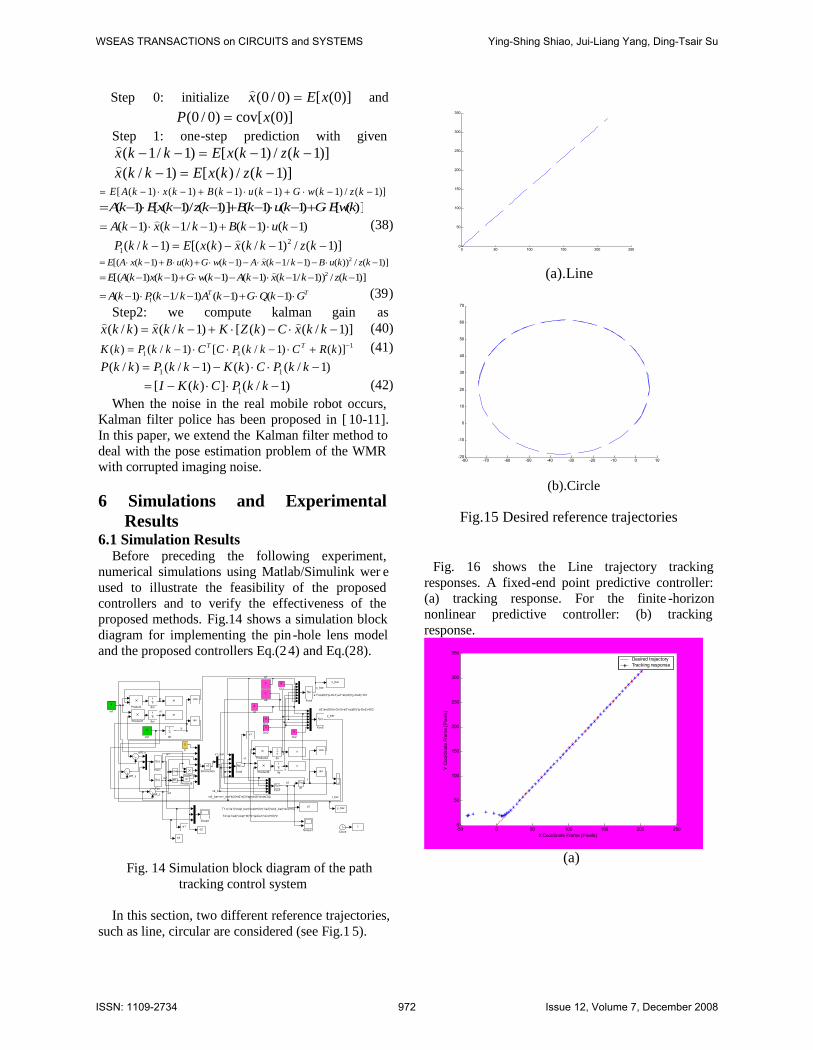
In this section, two different reference trajectories,such as line, circular are considered (see Fig.1 5).
(a).Line
(b).Circle
Fig.15 Desired reference trajectories
Fig. 16 shows the Line trajectory trackingresponses. A fixed-end point predictive controller:(a) tracking response. For the finite -horizonnonlinear predictive controller: (b) trackingresponse.
-50 0 50 100 150 200 2500
50
100
150
200
250
300
350
X Coordinate Frame [Pixels]
Y C
oord
inat
e Fr
ame
[Pix
els]
Desired trajectoryTracking response
(a)
0 50 100 150 200 2500
50
100
150
200
250
300
350
-80 -70 -60 -50 -40 -30 -20 -10 0 10-20
-10
0
10
20
30
40
50
60
70
WSEAS TRANSACTIONS on CIRCUITS and SYSTEMS Ying-Shing Shiao, Jui-Liang Yang, Ding-Tsair Su
ISSN: 1109-2734 972 Issue 12, Volume 7, December 2008

-50 0 50 100 150 200 2500
50
100
150
200
250
300
350
X Coordinate Frame [Pixels]
Y C
oord
inat
e Fr
ame
[Pix
els]
Desired trajectoryTracking response
(b)Fig. 16 Line trajectory tracking responses
Fig. 17 shows the Circle trajectory trackingresponses. A fixed-end point predictive controller:(a) tracking response. For the finite -horizonnonlinear predictive controller: (b) trackingresponse.
-80 -70 -60 -50 -40 -30 -20 -10 0 10-20
-10
0
10
20
30
40
50
60
70
X Coordinate Frame [Pixels]
Y C
oord
inat
e Fr
ame
[Pix
els]
Desired trajectoryTracking response
(a)
-80 -70 -60 -50 -40 -30 -20 -10 0 10-20
-10
0
10
20
30
40
50
60
70
X Coordinate Frame [Pixels]
Y C
oord
inat
e Fr
ame
[Pix
els]
Desired trajectoryTracking response
(b)Fig. 17 Circle trajectory tracking responses
Fig. 18(a) depicts the line-tracking path that iscorrupted with the noise. Fig. 18(b) shows that thecorrupted noise is removed. Fig. 18(c) depicts the
circle-tracking path that is corrupted with the noise.Fig. 18(d) shows the filtered circle trajectory. Fig.18 reveals that the noise effect on posture estimationhas been significantly reduced.
(a)
(b)
(c)
WSEAS TRANSACTIONS on CIRCUITS and SYSTEMS Ying-Shing Shiao, Jui-Liang Yang, Ding-Tsair Su
ISSN: 1109-2734 973 Issue 12, Volume 7, December 2008

(d)Fig. 18 The corrupted noise and Kalman filter
trajectory tracking responses
6.2 Experimental ResultsFig. 19(a) shows the resulting tracking responses
for the camera-space desired trajectory line.Furthermore, Fig. 19(b) displays the resultingtracking responses for of the camera -space desiredcircle trajectory.
Fig. 20 (a) shows that the Kalman filter trackingresponses for the desired line trajectoryexperimental result. Furthermore, Fig. 20(b)displays the resulting tracking responses for of theKalman filter desired circle trajectory. The Kalmanfilter indeed removes out measurement noise frommeasurements.
(a)
(b)Fig. 19 The experimental tracking responses for
the desired line trajectory
(a)
(b)Fig. 20 The experimental Kalman filter tracking
responsesThe computer simulation results and experimental
results have verified that two the predictive pathtracking controllers really achieve the mission ofpath tracking control. From the experimental resultsillustrated in Fig. 13 there exist fluctuations causedby the image noise. Although sometimes the WMRseems to detour the desire trajectory in the cameraspace, the image-recognition process maybe cause
WSEAS TRANSACTIONS on CIRCUITS and SYSTEMS Ying-Shing Shiao, Jui-Liang Yang, Ding-Tsair Su
ISSN: 1109-2734 974 Issue 12, Volume 7, December 2008

the errors. This situation can be avoided if theexperimental setup system is using Kalman filter.
7. ConcludesThis paper has studied methodologies and
techniques for control architecture design, pathtracking and implementation of a vision -basedwheeled mobile robot. The overall control systemconsists of three subsystems: the wirelesscommunication system, the DSP-based motioncontrol system for the WMR and the vision systemfor pattern recognition. Two kinematical, predictivepath tracking control laws have been proposed inorder to achieve asymptotical path tracking. Thedeveloped system obtains the posture of the WMRusing combination of the vision system and dead -reckoning device, such that the accumulated errorscaused by the numerical differentiation/integrationwill be reduced or even eliminated. The designedsystems together with proposed control laws havebeen successfully used to manipulate the WMRfollow the desired reference trajectories. The mainresults of this paper are summarized as below;
First, a DSP-based controlled WMR with internalcurrent feedback loop has been constructed. Thebuilt wireless communication system has beenimplemented for signal transmission. Through theproposed PID control, the WMR achieves goodtransient performance to track velocity or torquecommands. Aside form the simple PID control loop,the DSP-based low-level controller for the WMR isfurther constructed in order to perform sophisticatedpath tracking control laws. The WMR obtains theposture not only by the DR device but also by thevision system. The image-recognition system canprocess 15 frames per second by using one well -known color model, e.g. H-S model. Thesesubsystems are integrated to test the path trackingcontrol laws.
Second, two novel predictive control laws havebeen proposed for the system associated with thekinematical model, i.e. the model without theincorporation of its dynamic effects . In addition, theso-called pin-hole lens model has been supplied inthe procedure of the control laws design. Computersimulations and experimental results have alsoshown the feasibility and effectiveness of theproposed predictive controller associated with thekinematical model.
Third, there is noise reduction for pose estimationof the WMR by applying the Kalman filter toremove the noise corrupted the captured images, sothe Kalman filter can be applied in order to reducethe noise. Computer simulations and experimental
results have also shown the feasibility andeffectiveness of the proposed Kalman filterassociated with imaging processing.
References[1] J. Qiuling, X. Xiaojun, and L. Guangwen,
Formation Path Tracking Controller ofMultiple Robot System By High Order SlidingMode, Automation and Logistics, IEEEInternational Conference .18-21 Aug. 2007 ,pp.923 – 927
[2] J. Y. Lee, J. S. Yeon, and J. H. Park, Robustnonlinear control for flexible joint robotmanipulators, SICE, Annual Conference . 17-20Sept. 2007. pp.440 – 445
[3] B. Song, and J. W. Choi, Robust Non linearControl for Biped Walking with a VariableStep Size, SICE-ICASE, 2006. InternationalJoint Conference, Oct. 2006 Page(s):3490 –3495
[4] G. Lei, L. Qizheng, and W. Shiming, Design ofFuzzy Sliding-mode Controller for BicycleRobot, Nonlinear System Robotics andBiomimetics, ROBIO '06. IEEE InternationalConference. Dec. 2006 Page(s):176 – 180
[5] M. R. Heinen, and F. S. Osorio, NeuralNetworks Applied to Gait Control of PhysicallyBased Simulated Robots, Neural Networks,SBRN '06. Ninth Brazilian Symposium . Oct.2006 Page(s):26 - 26
[6] D. G, and R. RD, Robust adaptivebackstepping control for a nonholonomicmobile robot, Wilson, Systems, Man, andCybernetics, 2001 IEEE InternationalConference. Vol. 5, 7-10 Oct. 2001Page(s):3241 - 3245 vol.5
[7] A. Al-Mamun, Z. Zhu, P. Vadakkepat and T.H.Lee, Path Following Controller forGyroscopically Stabilized Single-WheeledRobot, Proceedings of the 9th WSEASInternational Conference on Automatic Control,Modeling & Simulation, Istanbul, Turkey, May27-29, 2007 11.
[8] De-Feng He, Hai-Bo Ji, Tao Zheng, Onrobustness of suboptimal min -max modelpredictive control, WSEAS TRANSACTIONSon SYSTEMS and CONTROL, Issue 8, Volume2, pp. 428-433. August 2007.
[9] R. Hedjar, R. Toumi, P. Boucher, and D.Dumur, Feedback nonlinear predi ctive controlof rigid link robot manipulations, Proceedingsof American Control Conference, Anchorage,AK, pp. 3594-3599, May 2002.
WSEAS TRANSACTIONS on CIRCUITS and SYSTEMS Ying-Shing Shiao, Jui-Liang Yang, Ding-Tsair Su
ISSN: 1109-2734 975 Issue 12, Volume 7, December 2008
[10] S. Kwon, K. W. Yang, and S. Park, AnEffective Kalman Filter Localization Methodfor Mobile Robots, Intelligent Robots andSystems, 2006 IEEE/RSJ InternationalConference. Oct. 2006 Page(s):1524 – 1529.
[11] J. Zhu, J. Park, and K. Lee, Robust Kalmanfilter of discrete-time Markovian jump systemwith parameter and noise uncertainty ,Proceedings of the 7th WSEAS InternationalConference on Simulation, Modelling andOptimization, Beijing, China, September 15-17,2007 .
WSEAS TRANSACTIONS on CIRCUITS and SYSTEMS Ying-Shing Shiao, Jui-Liang Yang, Ding-Tsair Su
ISSN: 1109-2734 976 Issue 12, Volume 7, December 2008