Patented Below Grade Fiber Distribution Hub
20
AP NAUTILUS ® Patented Below Grade Fiber Distribution Hub Installation and Operation Manual Turn-Key Enclosure Solutions 597 Evergreen Road Strafford MO 65757 417-736-2135 Toll Free: 855-736-2135 Web: www.amprod.us Form 36-0061-03 Ver. 06/16/2020
Transcript of Patented Below Grade Fiber Distribution Hub

AP NAUTILUS ®Patented Below Grade Fiber Distribution Hub
Installation and Operation Manual
Turn-Key Enclosure Solutions
597 Evergreen Road Strafford MO 65757
417-736-2135Toll Free: 855-736-2135
Web: www.amprod.usForm 36-0061-03Ver. 06/16/2020

2
AP NAUTILUS ®
THIS PAGE INTENTIONALLY LEFT BLANK
Page: 2
3
AP NAUTILUS ®
Table of Contents
Contacting Us ............................................................................................................................................................... 4
Safety First .................................................................................................................................................................... 5
Product Overview ........................................................................................................................................................ 6
lMeasurements ............................................................................................................................................................. 7
Enclosure Packaging .................................................................................................................................................. 8
Cabinet Applications .................................................................................................................................................. 9
Vault Installation “Grass Surround” ........................................................................................................................ 10
Vault Installation “Concrete and Pavement” ....................................................................................................... 12
Enclosure Access ....................................................................................................................................................... 14
Bonding and Grounding ......................................................................................................................................... 16
Closing and Securing ............................................................................................................................................... 17
Appendix A ............................................................................................................................................................... 19
Technical Support ........................................................................................................................................ 19
Warranty Policy ............................................................................................................................................ 19
Page: 3

4
AP NAUTILUS ®Contacting Us
American Products can be contacted for any issues that arise with the supplied product.
Technical assistance is available 9am to 4pm central standard time.
• Toll Free: (855) 736-2135• Phone: (417) 736-2135• Fax: (417) 736-9535• Email: [email protected]• Web: www.amprod.us
When calling, please have available, or if faxing or emailing, be sure to provide:
• Part Number • Serial Number • Date of Purchase • Date of Installation
Page: 4

5
AP NAUTILUS ®
DANGERIndicates a hazardous situation that, if not avoided, will result in death or serious injury. This signal word is to be limited to the most extreme situations.
WARNING Indicates a hazardous situation that, if not avoided, could result in death or serious injury.
CAUTION Indicates a hazardous situation that, if not avoided, could result in minor or moderate injury.
NOTICE:
Indicates information considered important, but not hazard-related (e.g. messages relating to property damage). The safety alert symbol shall not be used with this signal word. When a signal word is used for messages relating to property damage, NOTICE is the choice of signal word.WARNING: Never look directly into the end of a fiber that may be carrying laser light. Laser light is invisible and can damage your eyes. Viewing it directly does not close involuntarily as when viewing a bright light. Consequently, serious damage to the retina of the eye is possible. Should accidental eye exposure to laser light be suspected, arrange for an eye examination immediately.
Safety First This publication provides a description of the American Products AP NAUTILUS® Below Grade Level Enclosure. The mechanical descriptions, typical applications, installation instructions, safety guidelines, grounding and bonding are included.
Five types of messages may appear throughout this manual, identified by the following icons and signal words:
Read equipment manufacturer’s manual and this material before using this product. Failure to do so can result in serious injury or death.
Invisible Laser RadiationAvoid Direct Exposure to the Beam
Do Not Look Into Ends of Open Fibers
Page: 5

6
Important Labeling Information
Serial Number Label
Accepted Label
Inspected Label
AP NAUTILUS® Below Grade Enclosure for Type 6Pat. 10,362,710 B2
Tested to Standards:CSA C22.2 No. 94.1-2, UL 50, UL 50E
Pat. 10,362,710 B2
Powder Coating Tested to Standards:Telcordia GR487 for Telecommunications Enclosures
American ProductsLabel
AP NAUTILUS ®
Page: 6
7
AP NAUTILUS ®
Product Overview
The American Products AP NAUTILUS® Below Grade Level Enclosure was designed to provide below grade connectivity in an outside plant (OSP) environment when deployed in a specified below-grade vault/hand-hole. The AP NAUTILUS® provides for up to 72 hours of water intrusion protection when fully submerged below grade. The Enclosure (Cabinet) can be configured to support a variety of deployment strategies from distributed split to cross-connect configurations from 144 to 288 ports. The Enclosure provides a swing-up and locking mechanism for easy and quick single-door access to the Fiber connectivity building blocks that exist in many traditional cabinet splitters.
In outside plant application environments where placement or easement permitting is not cost-effective, the AP NAUTILUS® can leverage existing below grade assets/facilities in polymer concrete or High Density Polyethylene (HDPE) vaults/hand-holes by providing 144/288 ports of connectivity across a variety of transport and configuration methods. In environments where above grade placement of cabinets, pole-mounted or on the ground, is prohibited, the AP NAUTILUS® meets the requirement without sacrificing the key fiber management rules of access, bend radius protection, physical fiber protection, and route diversity that exist in current platforms that craft-people are familiar with.
The American Products AP NAUTILUS® Nautilus Below Grade Enclosure can also provide below grade connectivity to the traditional telephone network Serving Area Closure (SAC) that utilize existing copper networks. Even though the American Products AP NAUTILUS® was designed to provide below grade connectivity, it can also be used in the various other network applications such as; indoor applications, Outdoor wall applications or Ground-Level Applications when deployed in areas susceptible to flooding. The American Products AP NAUTILUS® is mounted onto a frame constructed of painted G-90 Galvanized steel with 300 series stainless steel fasteners and hardware. The AP NAUTILUS® is attached to the frame and are then placed and attached onto the polymer concrete or High Density Polyethylene (HDPE) vault/hand-hole. Once placed into the vault the AP NAUTILUS® can be operated by a one-handed operation to lift the enclosure for service and one-handed operation to store the enclosure into the vault/hand-hole.
Page: 7

8
AP NAUTILUS ®
Measurements
Page: 8
9
AP NAUTILUS ®
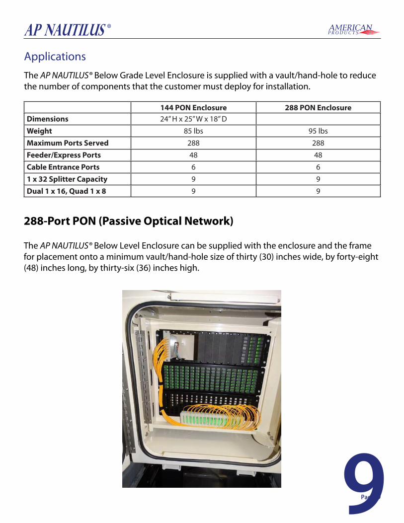
Applications
288-Port PON (Passive Optical Network)
The AP NAUTILUS® Below Level Enclosure can be supplied with the enclosure and the frame for placement onto a minimum vault/hand-hole size of thirty (30) inches wide, by forty-eight (48) inches long, by thirty-six (36) inches high.
The AP NAUTILUS® Below Grade Level Enclosure is supplied with a vault/hand-hole to reduce the number of components that the customer must deploy for installation.
144 PON Enclosure 288 PON EnclosureDimensions 24” H x 25” W x 18” D
Weight 85 lbs 95 lbs
Maximum Ports Served 288 288
Feeder/Express Ports 48 48
Cable Entrance Ports 6 6
1 x 32 Splitter Capacity 9 9
Dual 1 x 16, Quad 1 x 8 9 9
Page: 9

10
AP NAUTILUS ®
Vault Installation “Grass Surround”
“Grass Surround” InstallationInstallation instructions provide general information useful for parkway placement in “grass surround”, grass, dirt, or gravel applications. This guide cannot anticipate all situations that could develop in the field. Rather, it represents information applicable to common installation conditions.
Installation LocationLocation alone should not dictate product selection. “Pedestrian loading,” sometimes referred to as “Greenbelt”, defines our High Density Polyethylene (HDPE) thermoplastic body and covers vaults are intended for installation in landscape or grass surround areas where they will not be exposed to vehicular traffic. Exceptions to this rule include residential or light commercial mowers but do not include tractor/mowers in highway easements.
Site PreparationEnsure that national – local electrical and building codes, OSHA and company safety work rules are observed and provisions made for street flags, barricades and cones. Secure permits as required by city and company. WARNING: Buried Telecommunications Cables. Make sure to call 811 a few days before digging. Calling 811 will route to the local one-call center and ensure that utilities in the area of installation will be located and marked.
ExcavationPlan excavation approximately twelve to sixteen inches (12” - 16”) longer and wider than the actual dimensions of the vault being installed. Similarly, excavate six to eight inches (6” - 8”) deeper than the overall dimensions of the vault with cover in place. Note: Vault size is generally defined by the approximate cover dimensions. The vault actual measurements will differ. The dimensions above for determining the size of excavation provide sufficient volume for accommodating the maximum recommended select backfill. The volume of excavation would be reduced if a lesser volume of backfill material were hosen. Excavate hole to appropriate dimension with mechanical excavator or hand dig as appropriate. Confirm the excavation floor is level.
IMPORTANT: The AP NAUTILUS® Below Grade Level Enclosure frame is designed to fit the supplied vault/handhole that is: a minimum vault/hand-hole size of thirty (30) inches wide, by forty-eight (48) inches long, by thirty-six (36) inches high.
Page: 10
11
AP NAUTILUS ®
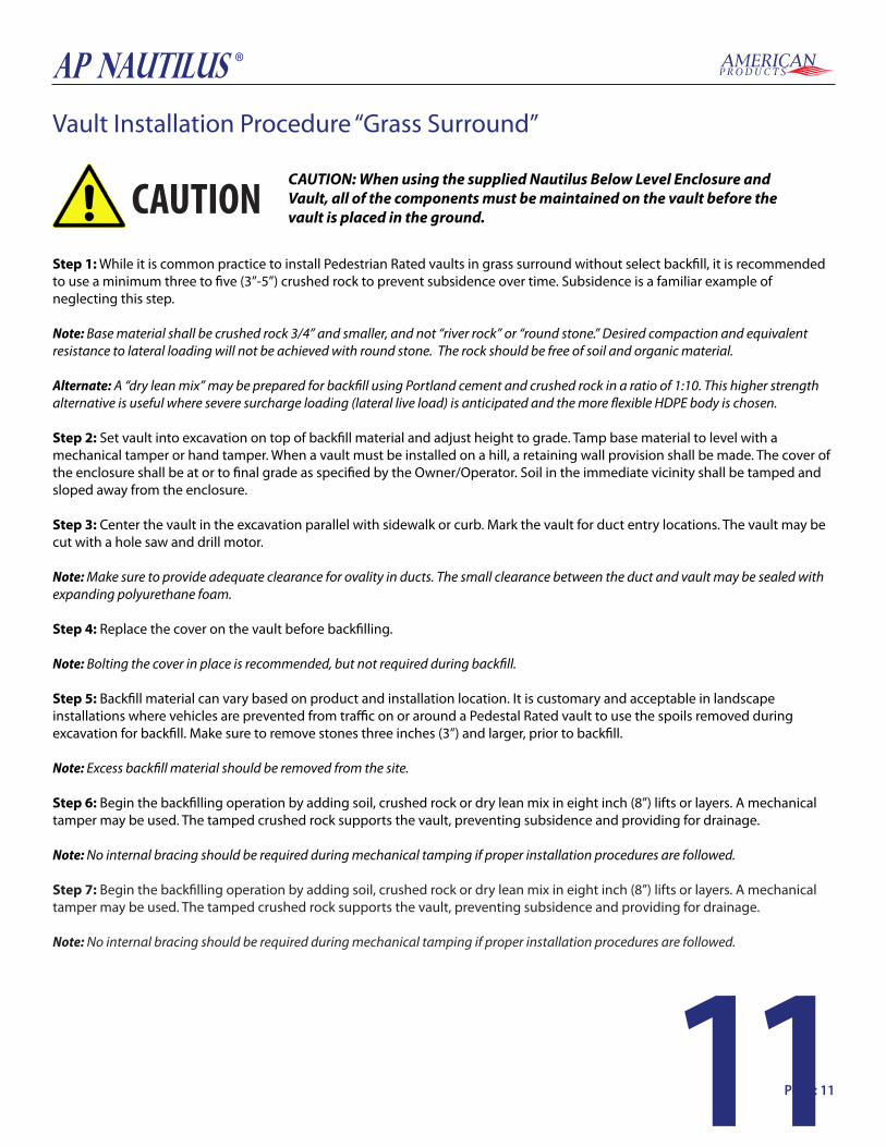
Vault Installation Procedure “Grass Surround”
Step 1: While it is common practice to install Pedestrian Rated vaults in grass surround without select backfill, it is recommended to use a minimum three to five (3”-5”) crushed rock to prevent subsidence over time. Subsidence is a familiar example of neglecting this step.
Note: Base material shall be crushed rock 3/4” and smaller, and not “river rock” or “round stone.” Desired compaction and equivalent resistance to lateral loading will not be achieved with round stone. The rock should be free of soil and organic material.
Alternate: A “dry lean mix” may be prepared for backfill using Portland cement and crushed rock in a ratio of 1:10. This higher strength alternative is useful where severe surcharge loading (lateral live load) is anticipated and the more flexible HDPE body is chosen. Step 2: Set vault into excavation on top of backfill material and adjust height to grade. Tamp base material to level with a mechanical tamper or hand tamper. When a vault must be installed on a hill, a retaining wall provision shall be made. The cover of the enclosure shall be at or to final grade as specified by the Owner/Operator. Soil in the immediate vicinity shall be tamped and sloped away from the enclosure. Step 3: Center the vault in the excavation parallel with sidewalk or curb. Mark the vault for duct entry locations. The vault may be cut with a hole saw and drill motor. Note: Make sure to provide adequate clearance for ovality in ducts. The small clearance between the duct and vault may be sealed with expanding polyurethane foam. Step 4: Replace the cover on the vault before backfilling.
Note: Bolting the cover in place is recommended, but not required during backfill. Step 5: Backfill material can vary based on product and installation location. It is customary and acceptable in landscape installations where vehicles are prevented from traffic on or around a Pedestal Rated vault to use the spoils removed during excavation for backfill. Make sure to remove stones three inches (3”) and larger, prior to backfill. Note: Excess backfill material should be removed from the site. Step 6: Begin the backfilling operation by adding soil, crushed rock or dry lean mix in eight inch (8”) lifts or layers. A mechanical tamper may be used. The tamped crushed rock supports the vault, preventing subsidence and providing for drainage. Note: No internal bracing should be required during mechanical tamping if proper installation procedures are followed.
Step 7: Begin the backfilling operation by adding soil, crushed rock or dry lean mix in eight inch (8”) lifts or layers. A mechanical tamper may be used. The tamped crushed rock supports the vault, preventing subsidence and providing for drainage.
Note: No internal bracing should be required during mechanical tamping if proper installation procedures are followed.
CAUTION: When using the supplied Nautilus Below Level Enclosure andVault, all of the components must be maintained on the vault before thevault is placed in the ground.CAUTION
Page: 11

12
AP NAUTILUS ®
Vault Installation “Concrete & Pavement”
Concrete and Pavement InstallationInstallation instructions provide general information useful for installing the “Shutter Box” in sidewalk and driveway placement with concrete surround. This guide cannot anticipate all situations that could develop in the field. Rather, it represents information applicable to common installation conditions.
Installation LocationSidewalk described as a walk for pedestrians at the side of a street. It is usually, but not always, an area between curb and parkway surrounded with concrete. Sidewalks are intended for pedestrian traffic with a safety factor for non-deliberate vehicular traffic. Driveway described as an access way from public road to a building or resident. Driveway is subject to occasional non-deliberate heavy vehicular traffic.
Site PreparationEnsure that national – local electrical and building codes, OSHA and company safety work rules are observed and provisions made for street flags, barricades and cones. Secure permits as required by city and company.
WARNING: Buried Telecommunications Cables. Make sure to call 811 a few days before digging. Calling 811 will route to the local one-call center and ensure that utilities in the area of installation will be located and marked.
ExcavationPlan excavation approximately twelve to sixteen inches (12”-16”) longer and wider than the actual outside dimensions of the vault to be installed. Similarly, excavate six to eight inches (6”-8”) deeper than the overall dimensions of the vault with the PC Ring and Cover in place.
Excavate hole to approximate dimension with mechanical excavator or hand dig as appropriate. Confirm the excavated floor is level.
Page: 12

13
AP NAUTILUS ®
Vault Installation Procedure “Concrete & Pavement”
Step 1: While it is common practice to install vaults in a concrete surround without the select backfill, it is recommended to use three to five inches (3”-5”) of crushed rock to prevent subsidence over time.
Note: Subsidence is a common example of neglecting this important step.
Step 2: Set vault into excavation on top of the backfill material and adjust height to final grade. Tamp base material, the PC Ring and cover of the enclosure should be at or to final grade as specified by the Owner/Operator. Soil in the immediate area shall be tamped and sloped away beginning 1” below the bottom of the PC Ring. The top of the vault with PC Ring and Cover attached should be parallel with the top of the sidewalk or curb final grade level. Backfill material can vary based on product and installation location. Be sure to remove stones three inches (3”) and larger from excavated area. Excess backfill material should be removed from the site to insure proper concrete thickness in surround. Step 3: For all product categories, begin the backfill operation by adding soil, crushed rock in eight inch (8”) even layers around exposed excavation. A mechanical tamper can be used during backfill operation. Note: The PC Ring and Cover should be installed and secured to the vault during the backfill operation. This will eliminate debris from entering into the vault and interfering with the cover fasteners, and will insure the cover fits properly upon completion of installation. Step 4: Crushed rocked backfill is typically specified. The tamped crushed rock supports the vault, preventing subsidence and providing for drainage. The excavated spoils have been used for backfill.
Note: Ensure that the soil is free of rocks larger than three inches.
Note: For installation in concrete and pavement sidewalk applications, plastic lids are NOT recommended. Boxes larger than 2 feet x 2 feet should be installed with an additional 8 inches to 10 inches of room. If using a 6 inch riser, excavation will need to be 6 inches deeper than standard installation.
Note: Install with cover and support beams in place. Prepare the excavation approximately 6 inch deeper than the overall height of the enclosure. The length and width of the excavation should be determined by adding 4 inches to 6 inches to the overall length and width of the vault/hand-hole or pull box.
Step 5: Place approximately 3 inches to 6 inches of compacted material such as sand or gravel in the bottom of the hole. Gravel is the recommended material because of its drainage characteristics. The compacted material should be leveled so the top of the vault/hand-hole or pull box is flush to the grade. Install with cover in place with shims on all sides and ends to prevent deflection. Step 6: Place selected backfill into the excavation at 1 foot lifts and compact either by manual compaction or by flooding the excavation. The backfill should be discontinued approximately 8 inches below the finished grade. The final 8 inches of the excavation should be finished with concrete. This should be accomplished by providing a form around the enclosure that would produce a 6 inch wide collar. Small shims should be placed between the cover and wall until concrete is set.
CAUTION: When using the supplied AP NAUTILUS® Below Grade Level Enclosure and Vault, all of the components must be maintained on the vault before thevault is placed in the ground.CAUTION
Page: 13

14
AP NAUTILUS ®
NOTICE: Due to the weight and size of the Nautilus Below Level Enclosure and frame, moving and handling will require proper hoisting equipment. Lifting eyelets are provided at the corners of the frame to facilitate hoisting.
There are 4 L-brackets that are attached to the side of the vault/hand-hole, locate these brackets. Once located, lower the cabinet using proper hoisting equipment into the vault/hand-hole. Lower the frame and enclosure until edge of the side upper rails bottoms out to the L-Brackets. Take the 4 Stainless Steel bolts that are provided andtighten the side upper rails tothe L-bracket which containpressed in nutserts.
Once the enclosure and frame are securedto the vault/hand-hole, pull the locking lever atthe bottom of the enclosure to disengage it from the frame. Using a one-handed operation lift the cabinet by the latch handle to its vertical serviceable position.
L-Brackets that attach to Vault
AP NAUTILUS® in the vertical serviceable position
Locking Lever
Page: 14

15
AP NAUTILUS ®
To open the door of the enclosure: depress the trigger at the upper part of the handle upwards, move the handle slightly to the left to disengage and swing the handle to the right to open the door.
To open the door of the enclosure: depress the trigger at the upper part of the handle upwards, move the handle slightly to the left to disengage and swing the handle to the right to open the door.
Enclosure Access
Page: 15

16
AP NAUTILUS ®
Bonding and grounding should be done in accordance with industry standard procedures and comply with local electrical codes.
The main cabinet ground bar is located in the rear center of the cabinet.
Bonding and Grounding
Page: 16

17
AP NAUTILUS ®
To close door: assure that the latch is in the disengaged position (latchpointing to the right) close door, actuate latch to the left until it engages in theclosed position and is centered to the door.
To lower the cabinet, pull the lever at the bottom of the enclosure to disengage it from the frame. Using a one-handed operation lower the enclosure to its horizontal storage position.
Once the cabinet is secured on its horizontal storage position, place the cover lid onto the vault/handhole and secure.
Closing Enclosure and Securing the Vault / Hand-Hole
CAUTION: If there is water in the vault/hand-hole, the water must be completely drained or pumped out prior to lowering the Nautilus Below Level Enclosure for storage.CAUTION
Page: 17

18
AP NAUTILUS ®
THIS PAGE INTENTIONALLY LEFT BLANK
Page: 18

19
AP NAUTILUS ®Appendix A Technical SupportAmerican Products can be contacted for any issues that arise with the supplied product. Technical assistance is available 9am to 4pm central standard time.
• Toll Free: (855) 736-2135• Phone: (417) 736-2135• Fax: (417) 736-9535• Email: [email protected]• Web: www.amprod.us
When calling, please have available, or if faxing or emailing, be sure to provide:• Part Number • Serial Number • Date of Purchase • Date of Installation
Warranty PolicyEnclosures designed and manufactured by American Products shall be warranted to be free of defects in material or workmanship for a period of 5 years (U.S. & Canada) and 3 years for International deployments from the date of shipment. Should the product be proven to be defective, American Products will have the option to repair or replace the product. Items included with the enclosures, not manufactured by American Products, will carry the original manufacturer’s warranty.
It is the responsibility of the buyer to communicate any special environmental concerns in which the enclosures will be utilized. Special materials may be required to allow for proper corrosion resistance for harsh environments. The warranty does not cover enclosures used in applications and environments for which they were not designed. Warranty does not cover abuse, modifications by others or reimbursement for unauthorized rework. At no time will American Products reimburse purchaser for unauthorized rework on any product.
Under no circumstances is American Products liable for any consequential damages, liquidated damages, loss in profits or revenues, costs of capital, downtime costs or damages related to our product performance.
Warranty ClaimsEnclosures found to be defective will be repaired or replaced with the same or comparable product. All warranty claims must be communicated to our customer service (855) 736-2135 department to obtain an RMA number. For warranty claims in the USA and Canada, freight will be managed and paid by American Products. For warranty claims outside of the USA and Canada, the customer will be responsible for managing the freight and freight expenses. Products being returned from other than US or Canada are to be returned to the factory in Strafford, MO to receive warranty resolution, once approved with an RMA.
Except for the express warranty stated above, American Products makes no other warranties with respect to the product, expressed or implied, including but not limited to merchantability or fitness for a particular purpose. Page: 19

597 Evergreen Road Straff ord, Missouri 65757
Phone: 417-736-2135 Toll Free: 855-736-2135
www.amprod.us
AMERICAN PRODUCTS LLC
10009691QM15
ISO 9001:2015