
Patent Number: 6,090,332 Date of Patent: Jul. 18,2000 Yu, et al., Photorefractive Polymers. 2....
54
I 11111 111111 l l 111 I l l 11 I l l 11 USOOOOOO3~A IIIII I l l 11 IIIII Il11 11111 111 l l 11 l l 11111111111111 United States Patent [191 [11] Patent Number: 6,090,332 Marder et al. [45] Date of Patent: Jul. 18,2000 - PROCESS OF CHANGING THE REFRACTIVE INDEX OF A COMPOSITE CONTAINING A POLYMER AND A COMPOUND HAVING LARGE DIPOLE MOMENT AND POLARIZABILITY AND APPLICATIONS THEREOF Inventors: Seth R. Marder, Pasadena, Calif.; Nasser Peyghambarian; Bernard Kippelen, both of Tucson, Ariz.; Boris Volodin, Los Angeles, Calif.; Eric Hendrickx, Glabbeek, Belgium Assignee: California Institute of Technology, Pasadena, Calif. Appl. No.: 09/078,211 Filed: May 13, 1998 Related U.S. Application Data Provisional application No. 601046,734, May 16, 1997. Int. C1.7 ..................................................... B29C 35/00 U.S. C1. .............................................................. 264/435 Field of Search ............................................... 2641435 References Cited U.S. PATENT DOCUMENTS 4,999,809 311991 Schildkraut et al. ................... 3651106 5,064,264 1111991 Ducharme et al. ..................... 3851130 5,115,336 511992 Schildkraut et al. ................... 3591263 5,184,323 211993 Schildkraut et al. ................... 3651124 5,501,821 311996 Willand et al. ......................... 2521582 5,552,915 911996 Khoo ...... 359194 OTHER PUBLICATIONS B. Kippelen, et al., Infrared Photorefractive Polymers and Their Applications for Imaging, Science, vol. 279, Jan. 2, 1998, pp. 54-57. D.D. Steele, et al. Transillumination Imaging Through Scat- tering Media by Use of Photorefractive Polymers, Optics Letters, vol. 23, No. 3, Feb. 1, 1998, pp. 153-155. E. Hendrickx, et al., Phase Stability of GuestiHost Photo- refractive Polymers Studied by Light Scattering Experi- ments,Appl. Phys. Lett. 71 (9), Sep. 1,1997,pp. 1159-1161. E. Hendrickx, et al., Synthesis and Characterization of Highly Efficient Photorefractive Polymer Composites with Long Phase Stability, Macromolecules, Reprinted from vol. 31, No. 3, (1998), pp. 734-739. Sandalphon, et al., Optical Dispersion of the Refractive Index Modulation in Low T, Photorefractive Polymers, Appl. Phys. Lett 71 (7), Aug. 18, 1997, pp. 873-875. K. Meerholz, et al., Stability Improvement of High-Perfor- mance Photorefractive Polymers Containing Eutectic Mix- tures of Electro-optic Chromophores, Adv. Matter, (1997), M. Liphardt, et al., High-Performance Photorefractive Poly- mers, Science, vol. 263, Jan. 21, 1994, pp. 367-369. S.M. Silence, et al. Electric Field-Dependent Nonphotore- fractive Gratings in a Nonlinear Photoconducting Polymer, Appl. Phys. Lett., vol. 64, No. 6, Feb. 7, 1994, pp. 712-714. C.A. Walsh & W. E. Moerner, Two-Beam Coupling Mea- surements of Grating Phase in a Photorefractive Polymer, J. Opt. SOC. Am. Bivol. 9, No. 9, Sep., 1992, pp. 1642-1647. 9, NO. 13, pp. 1043-1046. K. Sutter and P. Giinter, Photorefractive Gratings in the Organic Crystal 2-cyclooctylamino-5-nitropyridine Doped with 7,7,8,8-tetracyanoquinodimethane, J. Opt. SOC. Am, Bivol. 7, No. 12, Dec., 1990, pp. 2274-2278. G.G. Malliaras, et al., The Influence of Disorder on the Space Charge Field Formation in Photorefractive Polymers, J. Phys. D:Appl. Phys. 29 (1996), pp. 2045-2048. G.G. Malliaras, et al., Control of Charge Trapping in a Photorefractive Polymer, Appl. Phys. Lett. 66 (9), Feb. 27, G.G. Malliaras, et al., Transient Behavior of Photorefractive Gratings in a Polymer, Appl. Phys. Lett. 67 (4), Jul. 24, G.G. Malliaras, Holographic Time-of-Flight Measurements of the Hole-drift Mobility in a Photorefractive Polymer, Physical Review B, vol. 52, No. 20, Nov. 15, 1995-11, pp. B.E. Jones, et al., Photoconductivity and Grating Response Time of a Photorefractive Polymer, J. Opt. SOC. Am. Bivol. 11, No. 6, Jun., 1994, pp. 1064-1072. G.G. Malliaras, et al., Photorefractive Polymer Composite with net Gain and Subsecond Response at 633 nm, Appl. Phys. Lett. 65 (3), Jul. 18, 1994, pp. 262-264. M. Orczyk, et al., Enhanced Photorefractive Performance in a Photorefractive Polymeric Composite, J. Appl. Phys. 76 M. Orczyk, et al., Nonelectrooptic Nonlocal Photorefractive Effect in a Polymer Composite, Appl. Phys. Lett. vol. 67, M. Orczyk, et al., Photorefractive Effect in Fullerene-Doped Polymer Composite, CLEO '93 (Thursday afternoon), pp. 518-519, (1993). W.K. Chan, et al., Thermally Cross-Linkable Second Order Nonlinear Optical Polymers, ~ pp. 432433, (Undated). Y.M. Chen, et al. Stable Second-Order Nonlinear Optical Epoxy-Based Polymer, Mol. Cryst. Liq. Cryst. Sci. Tech- no1.-Sec. B, Nonlinear Optics, 1993, vol. 4, pp. 71-79. M.C.J.M. Donckers, et al, Net Two-Beam Coupling in a Polymeric Photorefractive Material, Optics Letters, vol. 18, No. 13, Jul. 1, 1993, pp. 1044-1046. (List continued on next page.) 1995, pp. 1038-1040. 1995, pp. 455-457. R14 324-R14 327. (9), NOV. 1, 1994, pp. 4995-4998. NO. 3, Jul. 17, 1995, pp. 311-313. Primary ExaminerTeo B. Tentoni Attorney, Agent, or FirmTimbach & Limbach LLP ABSTRACT Fused ring bridge, ring locked dyes that form thermally stable photorfractive compositions. The fused ring bridge structures are x-conjugated bonds in benzene-, naphthalene- or anthracene-derived fused ring systems that connect donor and acceptor groups. The donor and acceptor groups con- tribute to a high molecular dipole moment and linear polar- izability anisotropy. The polarization characteristics of the dye molecules are stabilized since the bonds in the fused ring bridge are not susceptible to rotation, reducing the oppor- tunity for photoisomerization. The dyes are compatible with polymeric compositions, including thermoplastics. The dyes are electrically neutral but have charge transport, electronic and orientational properties such that upon illumination of a composition containing the dye, the dye facilitates refractive index modulation and a photorefractive effect that can be utilized advantageously in numerous applications such as in optical quality devices and biological imaging. [571 5 Claims, 20 Drawing Sheets https://ntrs.nasa.gov/search.jsp?R=20080004064 2018-06-02T07:00:44+00:00Z
Transcript of Patent Number: 6,090,332 Date of Patent: Jul. 18,2000 Yu, et al., Photorefractive Polymers. 2....

I 11111 111111ll111 Ill11 Ill11 USOOOOOO3~A IIIII Ill11 IIIII Ill11 11111 111ll11ll11111111111111 United States Patent [191 [11] Patent Number: 6,090,332 Marder et al. [45] Date of Patent: Jul. 18,2000
-
PROCESS OF CHANGING THE REFRACTIVE INDEX OF A COMPOSITE CONTAINING A POLYMER AND A COMPOUND HAVING LARGE DIPOLE MOMENT AND POLARIZABILITY AND APPLICATIONS THEREOF
Inventors: Seth R. Marder, Pasadena, Calif.; Nasser Peyghambarian; Bernard Kippelen, both of Tucson, Ariz.; Boris Volodin, Los Angeles, Calif.; Eric Hendrickx, Glabbeek, Belgium
Assignee: California Institute of Technology, Pasadena, Calif.
Appl. No.: 09/078,211
Filed: May 13, 1998
Related U.S. Application Data Provisional application No. 601046,734, May 16, 1997.
Int. C1.7 ..................................................... B29C 35/00 U.S. C1. .............................................................. 264/435 Field of Search ............................................... 2641435
References Cited
U.S. PATENT DOCUMENTS
4,999,809 311991 Schildkraut et al. ................... 3651106 5,064,264 1111991 Ducharme et al. ..................... 3851130 5,115,336 511992 Schildkraut et al. ................... 3591263 5,184,323 211993 Schildkraut et al. ................... 3651124 5,501,821 311996 Willand et al. ......................... 2521582 5,552,915 911996 Khoo ...... 359194
OTHER PUBLICATIONS
B. Kippelen, et al., Infrared Photorefractive Polymers and Their Applications for Imaging, Science, vol. 279, Jan. 2, 1998, pp. 54-57. D.D. Steele, et al. Transillumination Imaging Through Scat- tering Media by Use of Photorefractive Polymers, Optics Letters, vol. 23, No. 3, Feb. 1, 1998, pp. 153-155. E. Hendrickx, et al., Phase Stability of GuestiHost Photo- refractive Polymers Studied by Light Scattering Experi- ments,Appl. Phys. Lett. 71 (9), Sep. 1,1997, pp. 1159-1161. E. Hendrickx, et al., Synthesis and Characterization of Highly Efficient Photorefractive Polymer Composites with Long Phase Stability, Macromolecules, Reprinted from vol. 31, No. 3, (1998), pp. 734-739. Sandalphon, et al., Optical Dispersion of the Refractive Index Modulation in Low T, Photorefractive Polymers, Appl. Phys. Lett 71 (7), Aug. 18, 1997, pp. 873-875. K. Meerholz, et al., Stability Improvement of High-Perfor- mance Photorefractive Polymers Containing Eutectic Mix- tures of Electro-optic Chromophores, Adv. Matter, (1997),
M. Liphardt, et al., High-Performance Photorefractive Poly- mers, Science, vol. 263, Jan. 21, 1994, pp. 367-369. S.M. Silence, et al. Electric Field-Dependent Nonphotore- fractive Gratings in a Nonlinear Photoconducting Polymer, Appl. Phys. Lett., vol. 64, No. 6, Feb. 7, 1994, pp. 712-714. C.A. Walsh & W. E. Moerner, Two-Beam Coupling Mea- surements of Grating Phase in a Photorefractive Polymer, J. Opt. SOC. Am. Bivol. 9, No. 9, Sep., 1992, pp. 1642-1647.
9, NO. 13, pp. 1043-1046.
K. Sutter and P. Giinter, Photorefractive Gratings in the Organic Crystal 2-cyclooctylamino-5-nitropyridine Doped with 7,7,8,8-tetracyanoquinodimethane, J. Opt. SOC. Am, Bivol. 7, No. 12, Dec., 1990, pp. 2274-2278. G.G. Malliaras, et al., The Influence of Disorder on the Space Charge Field Formation in Photorefractive Polymers, J. Phys. D:Appl. Phys. 29 (1996), pp. 2045-2048. G.G. Malliaras, et al., Control of Charge Trapping in a Photorefractive Polymer, Appl. Phys. Lett. 66 (9), Feb. 27,
G.G. Malliaras, et al., Transient Behavior of Photorefractive Gratings in a Polymer, Appl. Phys. Lett. 67 (4), Jul. 24,
G.G. Malliaras, Holographic Time-of-Flight Measurements of the Hole-drift Mobility in a Photorefractive Polymer, Physical Review B, vol. 52, No. 20, Nov. 15, 1995-11, pp.
B.E. Jones, et al., Photoconductivity and Grating Response Time of a Photorefractive Polymer, J. Opt. SOC. Am. Bivol. 11, No. 6, Jun., 1994, pp. 1064-1072. G.G. Malliaras, et al., Photorefractive Polymer Composite with net Gain and Subsecond Response at 633 nm, Appl. Phys. Lett. 65 (3), Jul. 18, 1994, pp. 262-264. M. Orczyk, et al., Enhanced Photorefractive Performance in a Photorefractive Polymeric Composite, J. Appl. Phys. 76
M. Orczyk, et al., Nonelectrooptic Nonlocal Photorefractive Effect in a Polymer Composite, Appl. Phys. Lett. vol. 67,
M. Orczyk, et al., Photorefractive Effect in Fullerene-Doped Polymer Composite, CLEO '93 (Thursday afternoon), pp. 518-519, (1993). W.K. Chan, et al., Thermally Cross-Linkable Second Order Nonlinear Optical Polymers, ~ pp. 432433, (Undated). Y.M. Chen, et al. Stable Second-Order Nonlinear Optical Epoxy-Based Polymer, Mol. Cryst. Liq. Cryst. Sci. Tech- no1.-Sec. B, Nonlinear Optics, 1993, vol. 4, pp. 71-79. M.C.J.M. Donckers, et al, Net Two-Beam Coupling in a Polymeric Photorefractive Material, Optics Letters, vol. 18, No. 13, Jul. 1, 1993, pp. 1044-1046.
(List continued on next page.)
1995, pp. 1038-1040.
1995, pp. 455-457.
R14 324-R14 327.
(9), NOV. 1, 1994, pp. 4995-4998.
NO. 3, Jul. 17, 1995, pp. 311-313.
Primary ExaminerTeo B. Tentoni Attorney, Agent, or FirmTimbach & Limbach LLP
ABSTRACT
Fused ring bridge, ring locked dyes that form thermally stable photorfractive compositions. The fused ring bridge structures are x-conjugated bonds in benzene-, naphthalene- or anthracene-derived fused ring systems that connect donor and acceptor groups. The donor and acceptor groups con- tribute to a high molecular dipole moment and linear polar- izability anisotropy. The polarization characteristics of the dye molecules are stabilized since the bonds in the fused ring bridge are not susceptible to rotation, reducing the oppor- tunity for photoisomerization. The dyes are compatible with polymeric compositions, including thermoplastics. The dyes are electrically neutral but have charge transport, electronic and orientational properties such that upon illumination of a composition containing the dye, the dye facilitates refractive index modulation and a photorefractive effect that can be utilized advantageously in numerous applications such as in optical quality devices and biological imaging.
[571
5 Claims, 20 Drawing Sheets
https://ntrs.nasa.gov/search.jsp?R=20080004064 2018-06-02T07:00:44+00:00Z

6,090,332 Page 2
OTHER PUBLICATIONS
J.C. Scott, et al, Photoconduction and Photorefraction in Molecularly Doped Polymers, Synthetic Metals, 54 (1993) 9
A. Grunnet-Jepsen and C.L. Thompson, High Performance Photorefractive Polymer with Improved Stability, Appl. Phys. Lett. 70 (12) Mar. 24, 1997, pp. 1515-1517. Y. Zhang, Monolithic Carbazole Oligomer Exhibiting Effi- cient Photorefractivity, Appl. Phys. Lett. 70 (22), Jun. 2,
T. Wada, et al., Novel Molecules for Photorefractive Appli- cation, Mol. Cryst. Liq. Cryst., 1996, vol. 280, pp. 71-78. T. Aoyama, et al., Electro-optic Effects in Mono and DiSubstituted Carbazoles, Nonlinear Optics, vol. 15, (1996) pp. 403406. T. Wada, et al., Multifunctional Chromophores for Mono- lithic Photorefractive Materials, Nonlinear Optics, vol. 15, (1996) pp. 103-110. Y. Zhang, et al., A Novel Approach to the Synthesis of Conjugated Carbazole Trimers as Multifunctional Chro- mophores for Photorefractive Materials, Tetrahedron Let- ters, vol. 38, No. 10, (1997), pp. 1785-1788. L. Wang, et al., Photorefractive Effect in Photoconductive Electro-optic Carbazole Trimer, Appl. Phys, Lett. 69 (6),
Y. Zhang, et al., Photorefractive Polymers Containing a Single Multifunctional Chromophore, Chem. Commun.,
T. Aoyama, et al., Xerographic and Electro-optic Studies of a Photorefractive Polymer, Mol. Cryst Liq. Cryst. 1997, vol,
P.M. Lundquist, et al, Holographic Digital Data Storage in a Photorefractive Polymer, Optics Letters, vol. 21, No. 12, Jun. 15, 1996, pp. 890-892. Y. Zhang, et al., Molecular Design of Carbazole Polymers for Photorefractive Applications, Mol. Cryst. Liq. Cryst.
S. Ducharme, et al., Observation of the Photorefractive Effect in a Polymer, Phys. Review Letters, vol., 66, No. 14, Apr. 8, 1991, pp. 1846-1849. J.J. Stankus, et al., Electric-field-switchable Strafified Bol- ume Holograms in Photorefractive Polymers, Optics Letters, vol. 19, No. 18, Sep. 15, 1994, pp. 1480-1482. J. Schildkraut, Photoconducting Electro-optic Polymer Films, Appl. Phys. Lett. vol. 58, No, 4, Jan. 28, 1991, pp. 34Ck342. R. Wortmann, et al., A Novel Sensitized Photochromic Organic Glass for Holographic Optical Storage, Appl. Phys. Lett. 69 (12), Sep. 16, 1996, pp. 1657-1659. Y. Zhang, et al., Photorefractive Properties of a Thiapyry- lium Dye Sensitized Polymer Composite: The Dynamics of Holographic Grating Formation and Erasure, Proc. SPIE 2285 (1994). S.M. Silence, et al., Optical Trap Activation in a Photore- fractive Polymer, Optics Letters, vol. 19, No. 22, Nov. 15,
W.E. Moerner and S.M. Silence, Polymeric Photorefractive Materials, Chem. Rev. 1994, 94, pp. 127-155. Z. Peng, et al., Large Photorefractivity in an Exceptionally Thermostable Multifunctional Polyimide, J. Am. Chem.
NO. 19, pp. 9-19.
1997, pp. 2949-2951.
AUg. 5, 1996, pp. 728-730.
1996, pp. 2325-2326.
295, pp. 63-66.
1997, V O ~ . 295, pp. 51-54.
1994, pp. 1822-1824.
SOC. 1994, 116, pp. 6003-6004.
S.M. Silence, et al., Subsecond Grating Growth in a Pho- torefractive Polymer, Optics Letters, vol. 17, No. 16, Aug.
S.M. Silence, et al., C,, Sensitization of a Photorefractive Polymer, Appl. Phys. Lett. 61 (25), Dec. 21, 1992, pp.
T. Kawakami and N. Sonoda, Photoinduced Refractive Index Change in a Photoconductive Electro-optic Polymer, Appl. Phys. Lett. 62, 2167 (1993). K. Sutter, et al., Photorefractive Properties of 4'-nitrobenzylidene-3-ace tamino-4-methoxyaniline, Optics Letters, vol. 18, No. 10, May 15, 1993, pp. 778-780. B. Kippelen, et al., Photorefractivity in a Functional Side-Chain Polymer, Physical Review B, vol. 48, No. 15,
M.J. Sansone, et al., Observation of the Photorefractive Effect in a Dialkylaminonitrostilbene Copolymer, Optics Letters, vol. 18, No. 17, Sep. 1, 1993, pp. 140Ck1402. B. Kippelen, et al., New Highly Efficient Photorefractive Polymer Composite for OpticalStorage and Image-Pro- cessing Applications, IEE, No. 19931190, Aug. 9, 1993. Luping Yu, et al., Photorefractive Polymers. 2. Structure Design and Property Characterization, Macromolecules, 26,
S.M. Silence, et al., Poly(si1ane)-based High-Mobility Pho- torefractive Polymers, J. Opt. SOC. Am. Bivol. 10, No. 12, Dec. 1993, pp. 2306-2312. Y.M. Chen, et al., New Photorefractive Polymer Based on Multifunctional Polyurethane, Appl. Phys. Lett. 64 (lo), Mar. 7, 1994, pp. 1195-1197. Kenji Yokoyama, et al., Photorefractive Effect in a Polymer Molecularly Doped with Low-Molecular-Weight Com- pounds, Jpn. J. Appl. Phys., vol. 33 (1994), pp. 1029-1033. S.M. Silence, et al., Optical Properties of Poly (N-vinylcar- bazo1e)-based Guest-Host Photorefractive Polymer Sys-
15, 1992, pp. 1107-1109.
2967-2969.
Oct. 15, 1993-1, pp. 10710-10718.
1993, pp. 2216-2221.
tems, Applied Optics, vol. 33, No. 11, Apr. 10,. 1994, pp. 2218-2222. Y. Zhang, et al., Thiapyrylium Dye Sensitization of Photo- refractivity in a Polymer Composite, Appl. Phys. Lett. vol. 64, No. 15, Apr. 11, 1994, pp. 1908-1910. Luping Yu, et al., Conjugated Photorefractive Polymer, Appl. Phys. Lett. 64(19), May 9, 1994, pp. 2489-2491. Technical Digest Series, vol. 8, Technical Digest Series vol. 9, IQEC '94 (May 10, 1994), pp 64-65. H. J. Bolink, et al., The Role of Absorbing Nonlinear Optical Chromophores in Photorefractive Polymers, Adv. Mater. 6
W.E. Moerner, et al., Photorefractive Polymers, Annu. Rev. Mater. Sci. 1997, 27, pp. 585-623. F. Wiirthner, et al., Merocyanine Dyes in the Cyanine Limit: A New Class of Chromophores for Photorefractive Materi- als, Angew. Chem. Int. Ed. Engl. 1997, 36, No. 24, pp.
A. Gmnnet-Jepsen, et al., Optical Limiting in a Photore- fractive Polymer, Mat. Res. SOC. Symp. Proc., vol. 479,
A. Grunnet-Jepsen & C.L. Thompson, Amplified Scattering in a High-gain Photorefractive Polymer, J. Opt. SOC. Am. B, vol. 15, No. 2, Feb. 1998, pp. 901-904. A. Grunnet-Jepson, et al., Measurement of the Spatial Phase Shift in High-Gain Photorefractive Materials, Optics Let- ters, vol. 22, No. 12, Jun. 15, 1997, pp. 874-876. A. Gmnnet-Jepsen, et al., High Performance Photorefrac- tive Polymer with Improved Stability, Appl. Phys. Lett. 70(12), Mar. 24, 1997, pp. 1515-1517.
NO. 7.8, 1994, pp. 574-577.
2765-2768.
1997, pp. 199-207.

6,090,332 Page 3
A. Grunnet-Jepsen, et al., Spontaneous Oscillation & Self- Pumped Phase Conjugation in a Photorefractive Polymer Optical Amplifier, Science, 277, Jul. 25,1997, pp. 549-552. A. Gmnnet-Jepsen, et al., Gain Enhancement by Moving Gratings in a Photorefractive Polymer, Optics Communica- tions, 145, Jan. 1, 1998, pp. 145-149. A. Gmnnet-Jepsen, et al., Systematics of Two-Wave Mix- ing in a Photorefractive Polymer, J. Opt. SOC. Am. B. vol. 15, No. 2, Feb. 1998, pp. 905-913. L. Mager, et al., High Net Gain at 514 nm in a Photorefrac- tive Polymer Doped with a Chalcone Derivative, Appl. Phys. Lett. 71 (16), Oct. 20, 1997, pp. 2248-2250. B. Darracq, et al., Stable Photorefractive Memory Effect in Sol-Gel Materials, Appl. Phys. Lett. 70 (3), Jan. 20, 1997,
N. Cheng, et al., Thermal Fixing of Refractive Gratings in a Photorefractive Polymer, Appl. Phys. Lett. 71 (13), Sep. 29,
Luping Yu, et al., Detailed Studies on a New Conjugated Photorefractive Polymer, J. Phys. Chem. vol. 99, No. 9,
C. Zhao, et al., Photorefractive Polymer with Side-Chain Second Order Nonlinear Optical & Charge-Transporting Groups, Chem. Mater. 1995, 7, pp. 1237-1242. Lian Li, et al., Photorefractive Effect in a Conjugated Polymer Base Material, Optics Communications 125 (1996), pp. 257-261. R. Wortmann, et al., Design of Optimized Photorefractive Polymers: A Novel Class of Chromophores, J. Chem. Phys, 105, (23), Dec. 15, 1996, pp. 10637-10647. P.M. Lundquist, et al., Organic Glasses: A New Class of Photorefractive Materials, Science, vol. 274, Nov. 15, 1996,
L. Wang, et al., Photorefractive Effect in a Photoconductive Electro-optic Carbazole Trimer, Appl. Phys. Lett. 69, (6),
Y. Zhang, et al., Photorefractive Composite Materials with Bi-functional Charge Transporting Second-order Nonlinear Optical Chromophores, J. Appl. Phys. 79(12) Jun. 15, 1996,
Y. Zhang, et al., Bifunctional Chromophore for Photorefrac- tiveApplications,Appl. Phys. Lett. 66 (3), Jan. 16,1995, pp.
A. Grunnet-Jepsen, et al., Spontaneous Oscillation & Self- Pumped Phase Conjugation in a Photorefractive Polymer Optical Amplifier, Science, vol. 277, Jul. 25, 1997, pp.
B. Kippelen, et al., Chromophore Design for Photorefractive Applications, J. Am. Chem. SOC. 1997,119, pp. 4559-4560. W.E. Moerner, et al., Orientationally Enhanced Photorefrac- tive Effect in Polymers, J. Opt. SOC. Am. Bivol. 11, No. 2, Feb. 1994, pp. 320-330. K. Meerholz, et al., A Photorefractive Polymer with High Optical Gain & Diffraction Efficiency Near loo%, Nature
F. Chaput, et al., New Nonlinear Sol-Gel Films Exhibiting Photorefractivity, Chem. Mater. 1996, 8, pp. 312-314. R. Burzynski, et al., Novel Optical Composites: Second-Order Nonlinear Optical and Polymeric Photore- fractive Materials for Optical Information Storage & Pro- cessing Applications, Opt. Eng. 35(2), Feb. 1996, pp.
pp. 292-294.
1997, pp. 1828-1830.
1995, pp. 2797-2802.
pp. 1182-1185.
AUg. 5, 1996, pp. 728-730.
pp. 8920-8929.
256-258.
549-552.
V O ~ . 371, Oct. 6, 1994, pp. 497-500.
443-451.
A.M. Cox, et al., Crystallization-Resistant Photorefractive Polymer Composite with High Diffraction Efficiency & Reproducibility, Appl. Phys. Lett. 68 (20), May 13, 1996,
G.G. Malliaras, et al., Photorefractive Polymer Composite With Net Gain & Subsecond Response at 633 nm, Appl.
M. E. Orczyk, et al., Enhanced Photorefractive Performance in a Photorefractive Polymeric Composite, J. Appl. Phys. 76 (9), Nov. 1, 1994, pp. 4995-4998. D. Kokron, et al., Launching of Guided Waves in a Photo- refractive Polymer by Two-Beam Coupling, Optics Letters,
Y. Zhang, et al., Photorefractive Polymers and Composites, Adv. Mater. 1996, 8, No. 2, pp. 111-125. S.M. Silence, et al., Photorefractive Polymers Based on Dual-Function Dopants, J. Phys. Chem. 1995, 99, pp. 40964105. S.M. Silence, et al., Quasinodestmctive Readout in a Pho- torefractive Polymer, Phys. Rev. Letters, vol. 73, No. 15,
K. Yokoyama, et al., Photorefractive Effect in a Polymer Molecularly Doped with Low-Molecular-Weight Com- pounds, Jpn. J. Appl. Phys., vol. 33 (1994), pp. 1029-1033. K. Yokoyama, et al., Large Photorefractive Effect in a Thermally Decomposed Polymer Compared with that in Molecularly Doped Systems, Appl. Phys. Lett. 65 (2), Jul.
0. Zobel, et al., Polysiloxane Based Photorefractive with High Optical Gain and Diffraction Efficiency (Undated). C. Poga, et al., Polysiloxane-Based Photorefractive Poly- mers for digital Holographic Data Storage, Appl. Phys. Lett. 69 (8), Aug. 19, 1996, pp. 1047-1049. C. Poga, et al., Photorefractivity in New Organic Polymeric Materials, SPIE, 1995. B.L. Volodin, et al., A Polymeric Optical Pattern-Recogni- tion System for Security Verification, Nature, vol. 383, Sep.
G.G. Malliaras, et al., Rapid Communication: The Influence of Disorder on the Space Charge Field Formation in Pho-
pp. 2801-2803.
Phys. Lett. V O ~ . 65, NO. 3, Jul. 18, 1994, pp. 262-264.
V O ~ . 20, NO. 22, NOV. 15, 1995, pp. 2297-2299.
Oct. 10, 1994, pp. 2047-2050.
11, 1994, pp. 132-134.
5, 1996, pp. 58-60.
torefractive Polymers, J. Phys. 6: Appl. Phys. 29 (1996), pp. 2045-2048. L. Yu, et al., Detailed Studies on a New Conjugated Pho- toreactive Polymer, J. Phys. Chem, 1995, 99, pp.
K. Meerholz, Amorphous Plastics Pave the Way to Wide- spread Holographic Applications, Angew. Chem. Int. Ed. Engl. 1997, 36, No. 9, pp. 945-948. E. Hendrickx, et al., High-Gain Photorefractive Polymers, SPIE, vol. 3281, pp. 268-276 (Undated). H. J. Bolink, et al., Photorefractive Polymers with Low Intrinsic Trap Density, SPIE, Jul. 1997.
R. Burzynski, et al., Photorefractive Composites with High- Band-Gap Second-Order Nonlinear Optical Chromophores, J. Appl. Phys. 78 (12), Dec. 15, 1995, pp. 6903-6907.
2797-2802.

U S . Patent Jul. 18,2000 Sheet 1 of 20 6,090,332
FIG. 1
0.
% contributions of limiting resonance forms 0,100 50,50 100,o
-
U + - increasing bond length alternation
increasing dipole moment
FIG. 2

U S . Patent Jul. 18,2000 Sheet 2 of 20 6,090,332
+
+ 0
BOND LENGTH ALTERNATION
FIG. 3
FIG. 4

U S . Patent Jul. 18,2000 Sheet 3 of 20 6,090,332
FIG. 5
Pyridine, reflux C t Amine
Pyridine, reflux D t Amine e
R = Me, R2= phenyl, 67%
R = R2= Hexyl, 62%
R l CN
CN
R, = R2= Me, 62%
R = R2 = Hexyl, 62%
FIG. 6a

U S . Patent Jul. 18,2000
R
CN Q NC R
R N q C N I
I CN CH3
Sheet 4 of 20 6,090,332
'5h13
Q-J&$p N 0 \
O’N i ‘gH13
CN 1
“3C
H3C ;N CN
1 CH3 1
Q NC
'5h13
HO
CN
CN
OH
FIG. 6b

U S . Patent Jul. 18,2000 Sheet 5 of 20
FIG. 7
qx&y!..- /
0 t s
-2 1 5 4-20
-1 204-1 0
6,090,332
-504-1 0
-1 8304-200
-950+/-160
FIG. a

U S . Patent
1.2 lo5
1 lo5
8 lo4
6 lo4
4 lo4
2 lo4
-2 lo4
0
6,090,332
FIG. 9a
0
8 lo4
6 lo4
4 lo4
2 lo4
0 320 400 480 560 640 720 800
? h m FIG. 9b

U S . Patent Jul. 18,2000 Sheet 7 of 20 6,090,332
h 1.5 IO
5 l o 4
0 320 400 480 560 640 720 800
Unm FIG. 9c
3.5 l o 5
3 l o 5 5 h
I; 2.5 10
0 320 400 480 560 640 720 800
Unm FIG. 9d

U S . Patent Jul. 18,2000 Sheet 8 of 20 6,090,332
h
7 I
E Y h
Y J
1.2
1
8
6
4
2
hlnm
1.6
1.4
1.2
1
8
6
4
2
- 320 400 480 560 640 720 800
Unm

U S . Patent Jul. 18,2000 Sheet 9 of 20 6,090,332
Me0
= -1 134 mV (irrev) E(ox) = 786 mV (irrev.) E (Red)
AE = 1900 mV
= -1486 mV (irrev) E(ox) = 826 mV (irrev.) E (Red) AE = 2312 mV
= -1431 mV (irrev) E(ox) = 1125 mV (irrev.) E (Red)
AE = 2556 mV
FIG. 10
E(Red)=-1172 mV(rev) E(ox) = 706 mV (irrev.)
AE = 1878 mV
E(Red)= -1265 mV (rev) E(ox) = 737 mV (irrev.)
AE = 2002 mV
E(Red)= -1099 mV (rev) E(ox) = 1294 mV (irrev.)
AE = 2393 mV
= -1030 mV (rev) E(ox) = 458 mV (irrev.) q T N - - 0 [ S E (Red) /
AE = 1488 mV
= -1 106 mV (rev) E(ox) = 476 mV (irrev.) E (Red)
AE = 1582 mV
FIG. 11

U S . Patent Jul. 18,2000 Sheet 10 of 20 6,090,332
z 0
z 0
/ 1 7-
z 0
z 0 $
z-
0 0 0
Lo
0 0 0 0
0 9 9
T- LI., z T-
0 0 0
0 0 0 9 9 v,
T- .r 1 9 1
0 0 in 7
0 0 0 7
0 0 L n
0
0 0 0 7 1
0 0 Lo 7
1
0 0 0 CY
[VI I

U S . Patent Jul. 18,2000 Sheet 11 of 20 6,090,332
Me0 OMe 0 Me0 OMe
1 -MeOH 145°C L
0 I A B
UMet
OMet
O V ?
C
CN
CN
D
FIG. 13
U S . Patent Jul. 18,2000 Sheet 12 of 20 6,090,332
nButylaniline, NaOf-Bu, Pd 2(dba)3, DPPF
R1+ Br
R = n-Bu 90%
R
1. SnCI2, HCI 2. Na2C03
1 -lodo-4-nitrobenzene NaOt-Bu, Pd2 (dba)3, DPPF
b
R
R = DBU, 40% R = H, 48%
R
J? R 1. C5Hl1COCI q 2. BH3SMe2 i;i"""""""'" \ /
R PNONH2 R R = = nBu, H, 100% 91% R = H, 88%
R R Q 1. HCOOH, AC 20 2. BH3SMe2
PN+ NCH3
L
Q R
R = n-Bu, 91 % R = H, 100%
R = H, 93% R=CqHg,86%
R PNONH2 FIG. 14

U S . Patent Jul. 18,2000 Sheet 13 of 20 6,090,332
1. SnC12,HCI
1. BTEAC. 50% NaOH, C6H13Br
N b N b
I I H C6H13
65%
I ‘gH 13
80%
I ‘gH 13
92%
1. HCOOH, HOAc 2. BH3SMe2
N - N I 62%
C6H 13 I
‘SH13
FIG. 15

U S . Patent Jul. 18,2000 Sheet 14 of 20 6,090,332
R1
pN R1
Mea% \
Pyridine, reflux
R 2 I
t .-+ \
Pyridine, reflux, 3d
I
Q 5 y N H C C H 1 3
N I
‘SH13
‘6Yl3
wN N
I ‘eH 13
FIG. 16 6.2%

U S . Patent Jul. 18,2000 Sheet 15 of 20 6,090,332
FIG. 17a
'N 0 \ \ \ \ -1- \ ' I 0 p
FIG. 17b

U S . Patent
0.8 -
0.6 -
0.4 -
0.2 -
0.0 -
Jul. 18,2000 Sheet 16 of 20 6,090,332
' t
SPACE
FIG. 18
X
1.0 I I
I I I I I
-0.6 -0.4 -0.2 0.0 0.2 0.4 0.6
FIG. 20b
0.02
0.01
0.00
-0.01
-0.02
FIG. 19
FIG. 20a
I I I I
-0.6 -0.4 -0.2 0.0 0.2 0.4 0.6 BOA

U S . Patent Jul. 18,2000 Sheet 17 of 20 6,090,332
). 0 1.0 E !z LL 0.8
0.6
LL W z
5 is 0.4
0.2
u, LL n n W
a 8 0.0 2
z I I I I I I I I I I I 0 10 20 30 40 50
APPLIED FIELD (V/pm)
2.0
1.5
1 .o
0.5
0.0
FIG. 21
I I I I I I I I I
- - TNFDMlcarbazole - - - - - - - TNFlcarbazole
-
500 600 700 800 900 1000
WAVELENGTH (NM)
FIG. 22

U S . Patent Jul. 18,2000 Sheet 18 of 20 6,090,332
1 .o
0.8
0.6
0.4
0.2
0.0
0 20 40 60 80 100
APPLIED FIELD (Wpm)
FIG. 23

U S . Patent
0
i
Jul. 18,2000 Sheet 19 of 20
f 0 cu 2 oc Q W 0 z W oc W LL W CT
71
= f
6,090,332

U S . Patent Jul. 18,2000 Sheet 20 of 20 6,090,332

6,090,332 1
PROCESS OF CHANGING THE REFRACTIVE INDEX OF A COMPOSITE
CONTAINING A POLYMER AND A COMPOUND HAVING LARGE DIPOLE MOMENT AND POLARIZABILITY AND
APPLICATIONS THEREOF
CROSS REFERENCE TO RELATED APPLICATIONS
This application claims the benefit of U.S. Provisional Patent Application No. 601046,734, entitled “Photorefrac- tive Materials with Enhanced Performance in Near Infrared and Visible Regions of the Electromagnetic Spectrum” filed May 16,1997, the disclosure of which is incorporated herein by reference.
ORIGIN OF INVENTION
The invention described herein was made in the perfor- mance of work under a NASA contract and is subject to the provisions of Public Law 96-517 (35 U.S.C. 202) in which the Contractor has elected to retain title. The invention was also partially supported by the United States Government through the Office of Naval Research (ONR Grant Nos. N00014-95-1-1319), Air Force Office of Scientific Research (AFSOR Grant No. AFS5 F49620-97-1-0200) and the National Science Foundation (NSF Grant No. CHE 94-08701, Amendment 001).
BACKGROUND OF THE INVENTION
1. Field of the Invention The invention relates to fused ring bridge, ring-locked
molecules featuring various donor and acceptor groups or donor- and acceptor-like heterocycles and a stable benzene-, naphthalene- or anthracene-derived polyene bridge, i.e., fused ring bridge, ring-locked compounds, as exemplified below, and methods of their use.
2. Description of the Related Art The basic elements of photorefractivity include
photosensitivity, photoconductivity and electrooptical activ- ity. As an example, the photorefractive (PR) effect enables the recording of optical information in three-dimensional solids through the optical generation of an internal space- charge field and refractive index changes in the solid, as described in P. Gunter and J. -P. Huignard, Photorefractive Materials and Their Applications, Vol. 1 and 2 (Springer, Berlin, 1988 and 1989), incorporated herein by reference. Due to high optical sensitivity and the ability to erase and rewrite information optically in real-time, photorefractive materials are expected to play a major role in photonic technologies. One special aspect of the PR recording mecha- nism is the non-zero phase shift that can exist between the optical intensity pattern and the stored phase replica. This so-called nonlocal response can be used to transfer energy between two interacting beams. For some applications, such as image amplification, a strong energy transfer is desired, as described in A. Grunnet-Jepsen, C. L. Thomson, W. E. Moerner, Science 277, 549 (1997). However, for other applications based on the recording and retrieval of stored holograms, the important material parameter is the dynamic range or index modulation Aq, and one of the current challenges is to increase it.
The photorefractive effect in inorganic crystals has been studied. The mechanism of the refractive index modulation by the internal space-charge field was based on the linear electro-optic effect (i.e., the Pockels effect), as described in
2 A. Ashkin, G. D. Boyd, J. M. Dziedic, R. G. Smith, A. A. Ballmann, and K. Nassau, Appl. Phys. Lett. 9, 72 (1966). More recently, polymers have emerged as new photorefrac- tive materials as described in S. Ducharme, J. C. Scott, R. J.
s Twieg, and W. E. Moerner, Phys. Rev. Lett. 66,1846 (1991), W. E. Moemner and S. M. Silence, Chem. Rev. 94, 127 (1994), Y. Zhang, R. Burzynski, S. Ghosal and M. K. Casstevens, Adv. Mater. 8, 111 (1996), B. Kippelen, K. Meerholz, and N. Peyghambarian in Nonlinear Optics of
i o Organic Molecules and Polymers, edited by H. S. Nalwa and S. Miyata (CRC, Boca Raton, 1997), p. 465, all of which are incorporated herein by reference.
Active organic polymers are emerging as key materials for advanced information and telecommunication technol-
15 ogy. Owing to their outstanding performance, structural flexibility, and lightweight, polymers are expected to play a major role in optical technology, especially when large-scale manufacturing of devices at low cost is crucial. Other important characteristics that may be desirable depending on
20 the application include sufficiently long shelf life, optical quality, thermal stability and processing ease. Multifunc- tional nonlinear optical polymers and molecular assemblies are intensively investigated for electrooptic and photorefrac- tive applications.
In addition, with the rapid improvement of the perfor- mance of guestihost PR polymer composites, as described in M. C. J. M. Donckers, S. M. Silence, C. A. Walsh, F. Hache, D. M. Burland, and W. E. Moerner, Opt. Lett. 18, 1044 (1993), M. Liphard, A. Goonesekera, B. E. Jones, S.
30 Ducharme, J. M. Takacs, and L. Zhang, Science 263, 367 (1994) and the report of near 100% diffraction efficiency in 105 pm thick samples containing a photoconducting sensi- tizer by K. Meerholz, B. L. Volodin, Sandalphon, B. Kippelen, and N. Peyghambarian, Nature 371, 497 (1994),
35 it became apparent that the Pockels effect alone could not account for the origin of the high refractive index changes. A detailed explanation of this effect was provided with the orientational enhancement model proposed by W. E. Moerner, S. M. Silence, F. Hache, and G. C. Bjorklund, J .
40 Opt. SOC. Am. B 11, 320 (1994) in which both the birefrin- gence induced by the orientation of the dopant molecules [M. G. Kuzyk, J. E. Sohn, C. W. Dirk,J. Opt. SOC. Am. B 7, 842 (1990), J. W. Wu,J. Opt. SOC. Am. B 8,142 (1991)l and the molecules electrooptic properties were reported to con-
Thus, on a molecular level, according to the oriented gas model [D. J. Williams in Nonlinear Optical Properties of Organic Molecules and Crystals; Vol. 1, edited by D. S. Chemla and J. Zyss (Academic Press, Inc., Orlando, 1987), K. D. Singer, M. G. Kuzyk, and J. E. Sohn, J . Opt. SOC. Am. B 4,968 (1987), molecular figure of merit F may be defined for the optimization of the PR effect:
F=A(T)$ACY+P~~ (1)
where A a is the polarizability anisotropy of the chromophore, p is its dipole moment, fl is its first hyperpolarizability, and A(T)=21(9 kT) is a scaling factor (kT is thermal energy).
Early PR polymeric compositions were based on dopant molecules (i.e., chromophores) such as 3-fluoro-4-N,N- diethylamino-nitrostyrene (FDEANST) and 2,5-dimethyl-4- p-nitrophenylazoanisole (DMNPAA) because of these dopants’ electro-optic properties. More recent PR polymeric
65 compositions, described in P. M. Lundquist, R. Wortmann, C. Geletneky, R. J. Twieg, M. Jurich, V. Y. Lee, C. R. Moylan, D. M. Burland, Science 274, 1182 (1996) (In this
25
45 tribute to the refractive index modulation changes.
55
60
6,090,332 3 4
reference, the value for refractive index q reported in the chemistry used to synthesize unbridged compounds. Exem- Table 2 for a sample with composition 2BNCM:PM- plary synthetic routes are described in L. G. S. Brooker MATNF 90:10:0.3 wt. % for which four-wave mixing (1939), U.S. Pat. No. 2,161,331; L. G. S. Brooker (1939), results are presented in FIG. 1, should read 1 . 5 ~ 1 0 - ~ instead U.S. Pat. No. 2,170,804; L. G. S. Brooker (1939), U.S. Pat. of ~ O X ~ O - ~ ) were based on dopants such as N-2-butyl-2,6- s No. 2,170,807; L. G. S. Brooker (1940), U.S. Pat. No. dimethyl-4H-pyridone-4-ylidenecyanomethylacetate 2,185,182; L. G. S. Brooker, F. L. White, (1941) U.S. Pat. (2BNCM) with large polarizability anisotropy, improving No. 2,231,659; L. G. S. Brooker, F. L. White (1944), U.S. the dynamic range by a factor of 1.5 over the best previous Pat. No. 2,341,357; L. G. S. Brooker, H. W. J. Cressman PR polymeric compositions doped with DMNPAA. (1946), U.S. Pat. No. 2,409,189; L. G. S. Brooker, G. H.
Using model calculations and bond order alternation i o Keyes (1948), U.S. Pat. No. 2,441,530; L. G. S. Brooker, G. theory, we have shown recently in B. Kippelen, F. Meyers, H. Keyes (1950), U.S. Pat. No. 2,493,748; L. G. S. Brooker, N. Peyghambarian, and S. R. Marder, J . Am. Chem. SOC. F. L. White (1950), U.S. Pat. No. 2,494,031; L. G. S. 119, 4559 (1997) that the orientational birefringence con- Brooker, et al., J. Am. Chem. SOC. 73, 5332-5350 (1951); tribution is enhanced for chromophores that are polarized and L. G. S. Brooker, et al., J . Am. Chem. SOC. 73, beyond the cyanine limit, i.e., for chromophores that feature is 5326-5332 (1951) which are incorporated herein by refer- both high A a and high p. ence.
In order to explore this molecular design rationale, the The present invention also teaches how the linear polar- present invention focuses on linear molecules such as izability anisotropy and large dipole moment of chro- polyenes, as opposed to chromophores that contain benzene mophores according to the invention are particularly useful rings in the bridge. These polyenes exhibit a considerable 20 components in photorefractive compositions operating in charge transfer that is confined along the quasi one- the electromagnetic spectrum between 500 and 1600 nm. dimensional x-conjugated bridge providing a large A a and Previous work reports on the theory and synthesis of dyes can lead to an important charge separation in the ground- and their second-order nonlinear optical properties, includ- state that provides large molecular dipole moment and ing C. B. Gorman, S. R. Marder, Pvoc. Nutl. Acud. Sci., USA polarizability anisotropy, as predicted in B. Kippelen, F. 2s 90, 11297-11301 (1993); H. Ikeda, Y. Kawabe, T. Sakai, K. Meyers, N. Peyghambarian, and S. R. Marder,J.Am. Chem. Kawasaki, Chem. Lett., 1803-1806 (1989); S. R. Marder, D. SOC. 119, 4559 (1997). Furthermore, given the known ther- N. Beratan, L. -T. Cheng, Science 252, 103-106 (1991); F. mal instability of donor-acceptor substituted polymethine Meyers, S. R. Marder, B. M. Pierce, J. L. BrCdas, J . Am. bridged chromophore dyes (where the polymethine bridge is Chem. SOC. 116, 10703 (1994), each of which is incorpo- formed from CH groups joined by single or double bonds) 30 rated herein by reference. However, in contrast to this at elevated temperatures, described below, we discovered previous work, this invention focuses on the photorefractive the importance of the structure of fused ring bridge, ring- efficacy of fused ring bridge, ring-locked compounds, locked dyes according to the invention described herein and whereas the previous papers described dyes having a simple exemplified below where the donors and the acceptors polymethine bridge. More importantly, the effect that leads induce a large molecular dipole moment and also increase 35 to the large photorefractive effect in chromophores accord- polarizability anisotropy. ing to the present invention is not based upon the chro-
mophores’ first hyperpolarizability, but rather on a strategy which we have implemented successfully. As described herein, we have been able to optimize an orientational
40 contribution to the refractive index based upon optimizing the molecular polarizability anisotropy and molecular dipole
SUMMARY OF THE INVENTION Many of the chromophores useful according to the inven-
tion can be described by a structural motif where fused ring bridge, ring-locked structures of the form described herein
Preliminary work in synthesis of charged fused ring are substituted with donors and acceptors (wherein either the bridge, ring-locked ionic cyanine-like compounds was donor or the acceptor or both have a dipole moment greater reported in Y. L. Slominskii, L. M. Shulezho, U h . Khim. so than 2 Debye) to induce a large molecular dipole moment, Zhu., 40, 625-629 (1974); F. S. Babichcv, N. N. Romanov, and also to increase the molecular polarizability anisotropy. Y. L. Slominskii, A. I. Tolmachev, Ukr: Khim. Zhu., 40, It is a further feature of the invention that the fused ring 1165-1170 (1975); Y. L. Slominskii, A. V. Kuleshin, A. I. bridge, ring-locked structure imparts a unusually high ther- Tolmachev, Zhu. Ovg. Khim., 6, 1936-1940 (1970); Y. L. mal stability to the molecules and that also prevents rotation Slominskii, A. L. Skul’bidenko, A. I. Tolmachev Ukr: Khim. 55 around bonds (e.g., photoisomerization) in the bridge to Zhu., 40, 1166-1173 (1974), which are incorporated herein prohibit changing of the dipole moment or polarizability by reference. Work on the synthesis of anthracene-like fused anisotropy due to the rotation. ring bridge, ring-locked cyanines has also been reported by Chromophores according to the invention are electrically y . L. Slominskii, A. L. Skul’bidenko, A. 1. Tolmachev, zhu. neutral molecules with desirable orientational and transport Ovg. Khim., 11,392-397 (1975); G. Heilig, W. Luttke Chem. 60 properties such that upon illumination of a composition Bev., 119, 3102-3108 (1986); G. Heilig, W. Luttke, Chem. containing the chromophore, the chromophorc facilitates Bev., 120, 1863-1866 (1987); G. Heilig, W. L&e, Chem. charge transport and refractive index modulation. Bev., 121, 407410 (1988), all of which are incorporated We have found that molecules which take these forms can herein by reference. be designed to operate in methods wherein the
In contrast, this invention teaches how to synthesize fused 65 chromophorcs, alone or as part of a polymeric composition, ring bridge, ring-locked dyes of the type shown in the upon application of a field (either externally applied or General Structures 1, 2 and 3 below, by adapting the internally created in the presence of light) induce or change
A O D A C Q D moment.
45 A mD

6,090,332 5
the angular distribution of the chromophores, resulting in a change in the composition’s refractive index. In particular, chromophores in this invention can be used, even at rela- tively high loadings, to impart photorefractivity (e.g., to a polymeric composition) without adversely affecting other important properties, such as thermoplasticity or optical transparency. These compositions can be particularly advan- tageous for fabricating thermally stable, optical quality devices, e.g., by injection molding techniques, since heating of the composition to melt the chromophore followed by quenching to stabilize the chromophore in solution can be avoided. Phase separations observed with other chro- mophores can be avoided. Thus, photorefractive composi- tions according to the invention have great utility in a variety of applications, including optical recording and imaging of biological tissues.
BRIEF DESCRIPTION OF THE DRAWINGS
The invention will be better understood by reference to the following drawings, in which:
FIGS. la-le schematically illustrate the effect of donor and acceptor strength and polyene bridge structure on bond length alternation in prior art molecules and those according to the invention as exemplified by the contribution of the two limiting resonance forms (electrically neutral and charge separated forms) to the ground-state structure of the mol- ecule;
FIG. 2 illustrates the contribution of the neutral and charge separated resonance forms to molecular structure as a function of the extent of ground-state polarization of the molecule;
FIG. 3 graphically illustrates the correlation of fl with bond length alternation for a donor-acceptor substituted chromophore;
FIG. 4 illustrates examples of fused ring bridge, ring- locked dyes with heterocyclic donors and diethylthiobarbi- turic acid acceptors according to the invention;
FIG. 5 illustrates examples of fused ring bridge, ring- locked dyes with heterocyclic donors and phenylisoxozo- lone acceptors according to the invention;
FIGS. 6a and 6b respectively illustrate a reaction scheme to form polarized fused ring bridge, ring-locked dyes and examples of fused ring bridge, ring-locked dyes with amine or carbazole donors and dicyanomethylidene and phenyl- isoxazolone acceptors according to the invention;
FIG. 7 illustrates a fused bridge, ring-locked dye with a di-n-hexylamino donor and a dicyanomethylidene acceptor according to the invention;
FIG. 8 presents EFISH generation data (shown directly below the chemical structure of selected compounds accord- ing to the invention) giving values of pfl in units of lo-,’ esu;
FIGS. 9a-9f are UV-visible spectra of selected fused ring bridge, ring-locked dyes according to the invention that are near the cyanine limit or slightly beyond;
FIGS. 10 and 11 present oxidation and reduction poten- tials for donor-acceptor-substituted chromophores of the prior art and those according to the invention, respectively;
FIG. 12 presents cyclic voltammograms (CV) of fused ring bridge, ring-locked dyes according to the invention (solid line) and simple polyene (dashed line) dyes;
FIG. 13 shows a reaction scheme to form x-conjugated methoxy-thiobarbituric acid dyes according to the invention;
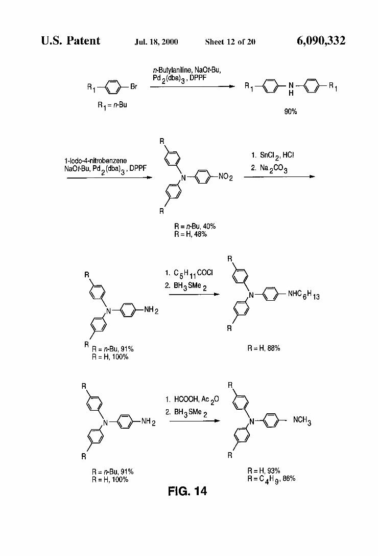
FIG. 14 shows a reaction scheme to form triphenylamine- substituted derivatives of dyes according to the invention;
S
10
1s
20
2s
30
3s
40
4s
so
5s
60
65
6 FIG. 15 shows a reaction scheme to form carbazole
derivatives of dyes according to the invention; FIG. 16 shows a reaction scheme exemplifying the rela-
tive reactivities of triphenylamine and carbazole derivatives of dyes according to the invention;
FIG. 17 shows a reaction scheme whereby selected fused ring bridge, ring-locked dyes according to the invention are formed;
FIG. 18 illustrates spatially modulated orientation of molecules according to the invention after formation of a photorefractive hologram;
FIG. 19 is a schematic representation of the chromophore (CH,),N(CH=CH),CHO that defines the molecular frame xyz and the laboratory frame XYZ;
FIGS. 20a and 20b are graphs providing electrooptic (flp) and orientational (A(T)Aap2) contributions and figure of merit, respectively, for (CH,),N(CH=CH),CHO as a func- tion of bond order alternation;
FIG. 21 is a graph of normalized diffraction efficiency of DHADCMPN:PVKECZTNF measured at 633 nm;
FIG. 22 is a graph comparing the linear absorption of intermolecular complex TNFDM:carbazole with that of TNF:carbazole;
FIG. 23 graphically compares the diffraction efficiency of D H A D C M P N : P V K : E C Z : T N F D M w i t h D M N - PAA:PVKECZ:TNFDM as a function of the applied field;
FIG. 24 schematically illustrates experimental setup for transillumination imaging with a photorefractive polymeric composition according to the invention; and
FIGS. 2% and 25b are images of the resolution target after passing through 1 cm of 0.06 wt % water suspension of 0.548 pm polystyrene spheres filtered with a 150 fs pulse and a cw Ti-sapphire laser, respectively.
DETAILED DESCRIPTION OF THE PREFERRED EMBODIMENTS
To ensure a complete understanding of the invention, the following definitions are provided:
By the term “acceptor”, it is meant an atom or group of atoms with a high electron affinity that can be bonded to a x (pi)-conjugated bridge. Exemplary acceptors, in order of increasing strength, are: C(O)NR,<C(O)NHR<C(O)NH~~C(O)OR~C(O)OH<C
Other acceptors that have accepting strength greater than C(0)R include:
(O)R<C( O)H <CN<S( O,)R<NO,

7 -continued
@
/ * I
6,090,332 8
The term “chromophore” is used herein to be synonymous to dye, i.e., a chromophore is a molecule or aggregate of molecules that can absorb electromagnetic radiation or be polarized by the field associated with the electromagnetic spectrum.
By the phrase “cyclic voltammetry (CV)”, it is meant a process in which the potential of an electrode is varied relative to a well-characterized oxidation-reduction couple and the current flow between said electrode and a counter electrode is measured. A plot is usually made of the current on the y axis versus potential on the x axis. A more complete description of CV can be found in A. J. Bard and L. R. Faulkner, Electrocheinical Methods, Wiley-Interscience,
IS New York, 1980, Chapter 6, which is incorporated herein by reference.
By the phrase “dipole moment”, it is meant the product of the charge separation in molecule times the distance over which the charge is separated.
By the term “donor”, it is meant an atom or group of atoms with a low ionization potential that can be bonded to a x (pi)-conjugated bridge. Exemplary donors, in order of increasing strength, are:
2s I<Br<Cl<F<OC(O)R<SH<OH<SR<OR<NHC(O)
Other donors that have donating strength greater than SR
20
R<NH,<NHR <NR,<S-<O-
include:
3s
40
4s
so
Where R is as defined below as for R,, and X(0) indicates that the element oxygen is double bonded to the element X and * indicates the point of attachment to the x-conjugated bridge. 5s
Amore complete description of what is meant by electron donors or donating groups and electron acceptors or electron accepting groups can be found in J. March, Advanced Organic Chemistry: Reactions, Mechanisms and Structure, Fourth edition, Wiley-Interscience, New York, 1992, Chap- 60 ter 9, which is incorporated herein by reference.
By the phrase “aromatic group”, it is meant a carbocyclic group that contains 4n+2 x electrons where n is an integer.
By the term “birefringence”, it is meant that a material
By the term “bridge”, it is meant that a molecular frag-
Q-- Q-1 /” R /”
R
exhibits at least two distinct indices of refraction. 65
ment that connects two or more chemical groups.

9 -continued
Se Se
6,090,332 10
with a significantly higher degree of freedom for motion of polymer chains. A more complete description of glass tran- sition temperature can be found in G. Odian, Principles of Polymerization, Second Edition, John Wiley and Son, New
5 York, 1981, which is incorporated herein by reference. By the phrase “ground state polarization”, it is meant the
fractional amount of charge transferred from a donor group to an acceptor group in the ground state of a molecule.
By the phrase “heteroaromatic group”, it is meant a cyclic group of atoms, with at least one atom within the ring being an element other than carbon, that contains 4n+2 x-electrons where n is an integer. A more complete description of aromaticity and heteroaromaticity can be found in J. March, Advanced Organic Chemistry: Reactions, Mechanisms and Structure, Fourth edition, Wiley-Interscience, New York, 1992, Chapter 2.
By the term “hologram”, it is meant a refractive modu- lation recorded in a material by the interference pattern of an optical wave containing the phase and amplitude modulation information of an object with a reference optical wave.
By the term “index of refraction”, it is meant the ratio of the speed of light in vacuum to the speed of light in a medium, such as a gas, liquid or solid.
By the phrase “infrared wavelengths”, it is meant elec- tromagnetic radiation having a wavelength longer than that
By the phrase “molecular figure of merit”, it is meant a formula containing several variables that can be utilized to evaluate the overall performance of a material for a particu-
10
20
25 that can be perceived by the human eye.
By the phrase “electro-optic activity, it is meant the lar change in optical properties of a material in response to a an 3o BY the Phrase ‘‘near infrared”, it is meant the region ofthe electric field. electromagnetic spectrum where light has a wavelength of
By the phrase “extinction coefficient”, it is meant the 700-2500 nm. absorbance of a solution containing a dye divided by the By the term “photoconductivity”, it is meant a process by product of the pathlength times the concentration in moles of which the conductivity of a material changes from that of an dye molecules per liter of solution (or molarity, M). insulator wherein the conductivity u changes from o < ~ O - ’ ~
By the phrase “fused ring bridge, ring-locked structure”, 35 ohm-’ Cm-’ to 0>10-14 ohm-’ Cm-’ upon exposure to light. it is meant the benzene-, naphthalene- or anthracene-based By the term “photoisomerization”, it is meant the change structures shown below wherein polymethine bonds join a in the geometrical orientation of bond in a molecule as a donor group D and an acceptor group Aand wherein rotation result of the interaction of the molecule with light (e.g., about atoms bonded together is prevented. Rotation is con- visible Or near infrared). sidered to be prevented if the dipole moment of the acceptor 40 By the term “photorefractivity”, it is meant an effect based group adds vectorially in substantially the same direction as On both Photocond~cting and electro-oPtic Properties of a the dipole moment of the donor group or the charge transfer material that can lead to high refractive index variations vector. In this context, “substantially in the same direction” illumination by low-Power lasers. TWO laser beams
that the angle between the vectorial sum of the dipole intersecting in a photorefractive material create an interfer- moments of the donor and acceptor and the vector repre- 45 ence pattern with a strongly heterogeneous distribution of senting the molecular dipole moment is within 0260 degrees light intensity. Excess charges generated through optical and also that the vectorial sum of the dipole moments of the in the high intensity regions migrate to the donor and the acceptor is within 0260 degrees of the charge regions of low intensity, leading to charge separation and the transfer vector, M~~~ preferably, these angles are within build-up of an internal electric field. Because the material is 0 ~ 2 0 degrees; even smaller angles are most preferred, Under SO electro-optic, the internal electric field changes the refractive these conditions, the bonds in the fused ring bridge are index of the material. As a result, the initial light distribution considered to be “ring-locked”, ~~~~~l~~~ structures is optically encrypted in the form of a refractive index include pattern in the material. Due to trapping of charge carriers,
the internal space-charge field and the corresponding refrac- ss tive index grating have a lifetime ranging from nanoseconds
to several years depending on the composition of the pho- torefractive material.
By the term “photosensitivity”, it is meant the ability of a molecule or material to change one or more of its prop-
60 erties either transiently or permanently in response to appli- cation of light (e.g., visible or near infrared). A photosensi- tive process could be used to transfer an electron from one molecule to another molecule upon application of visible or near infrared light.
By the phrase “polarizability anisotropy”, it is meant the difference in the polarizability of a molecule along one axis and the polarizability of the molecule on a second axis.
D Q D A Q
D
By the phrase “glass transition temperature”, it is meant 65 the temperature above which a glassy polymer becomes rubbery. The glass transition temperature, ‘lg, is associated

6,090,332 11
By the term “polyene”, it is meant a x-conjugated material comprising a series of alternating single and double bonds. More generally, as used herein, this term defines a linear sequence of methine (CH) units linked by a alternating sigma bond and between 0 and 1 x bonds.
By the phrase “reduction peak”, in the context of a cyclic voltamogram, it is meant the potential at which the flow of current from the electrode to the molecule that is accepting electrons is maximized.
By the phrase “refractive index modulation amplitude”, it is meant the amount the magnitude of the refractive index in a material can be varied tunably by an external stimulus.
By the phrase “reversibility of an oxidation process”, it is meant that current flow measured by cyclic voltammetry for re-oxidation of an electrochemically reduced species is the same as that observed upon the initial oxidation, the oxida- tion process is said to be reversible. Similarly, when current flow measured by cyclic voltammetry for re-reduction of an electrochemically oxidized species is the same as that observed upon the initial reduction, the reduction process is said to be reversible. The significance of such a situation is the molecule does not decompose rapidly after the initial oxidation or reduction event. Reversibility could impact a molecule’s efficacy in transporting charges.
By the phrase “semiconductor quantum well”, it is meant a thin semiconductor of sufficient thinness that the energy levels for an electron or hole are quantized.
By the term “transilluminating”, it is meant that imaging through a scattering medium is carried out by isolating the nonscattering photons and filtering out the scattering light.
By the phrase “visible wavelengths”, it is meant wave- lengths of light perceivable by the human eye (typically between 400 and 700 nm).
Other terms used herein are explained below.
Introduction
The present invention generally relates to molecules hav- ing transport, electronic and orientational properties that can be modified upon photoexcitation such that charge transfer can be induced which in turn enhances birefringence in a composition containing the molecules. For example, when a thermoplastic polymeric matrix is doped with a molecule according to the invention, optically clear, thermally stable photorefractive materials can be produced which are suitable for injection molding processes and capable of relatively long term storage.
The molecules have structures according to the following general formulas, wherein an asterisk (*) in a given structure identifies the point of attachment to the functional group and that the atom adjacent to the asterisk is missing one hydro- gen that would normally be implied by the structure in the absence of the asterisk):
“-” in the following explication indicates a single bond
“=” in the following explication indicates a double bond between 2 atoms
between 2 atoms
General Structure 1
12 -continued
General Structure 2
General Structure 3
Re Rf R, 1s
where D can be: NR,R,, OR,, SR,, PR,R, or
20
2s
30
3s
40
4s
so
5s
60
65

13 -continued
6,090,332 14
-continued
Q-,: Rb /"
And A can be:
")*
N C
Rco2c>* N C
0
0 k1: I Rd
10 (D8)
R,, R,, R,, R,, Re Rf, R, are independently selected from: H; a linear or branched alkyl group (see Note 1) with up to 25 carbons;
1s -( CH,CH,O),( CH),OR, 1; -( CH,CH,O),( CH),
-( CH,CH,O),( CH),CN; -( CH,CH,O),( CH),Cl; -(CH,CH,O),(CH),Br; -(CH,CH,O),(CH),I; -(CH,CH,O),(CH),Phenyl; -(CH,CH,O),(CH), Benzyl; various aryl or carbazole groups (see NOTE 2); various fused aromatic rings (see NOTE 3); and noth- ing thing if the combinations of general structure, D or A does not include one of the subscripted R groups listed above (see NOTE 4).
Ral, Ra2, and R,, are independently selected from: H; a linear or branched alkyl group with up to 25 carbons; and nothing where A is a divalent element;
Ral, Ra2, and R,, may also be carbazole attached to through the nitrogen of the heterocyclic ring; and
where x is e 1 0 and y is 1-25. NOTE 1: In general, alkyl groups set forth in the above
formulas include those groups having up to 25 carbon atoms 3s and includes both branched and straight chain alkyl groups.
Exemplary alkyl groups include methyl, ethyl, propyl, butyl, pentyl, hexyl, heptyl, octyl, nonyl, in the normal, secondary, is0 and neo attachment isomers.
NOTE 2: Aryl and carbazole groups of R,, R,, R,, R,: R, R,, R,, R, can be an aryl group of up to 20 carbon
(excluding substituents) aromatic ring systems where aryl includes:
NR,zR, 3; -( CHz CHz O),( CH), C 0 NRa2R,3;
2o
2s
30
(A2)
('43) 40
RAK RA09 I I
5s
RA13 RA14 ('4-5) 0
0 S I

6,090,332 15 16
-continued NOTE 5: Aryl and carbazole groups of R,#,, R,,,, RA#3: R,#,, R,,, RA#3 can be an aryl or carbazole group of up
to 20 carbon (excluding substituents) aromatic ring R A ~ ~ Q rb R m 3 5 systems where aryl includes:
RA20 RA21 RA22 R B 0 3 @ 3 0 1 R B o 6 ~ *
10 R A 3 4 ~ Y+ Rm8 RB04 RB05 RB07 RBOS
R ~ 3 5 RA36 RA37 1s R B 1 1 @ r q R B 1 6
R ~ 1 2 RBl5 E can be: S; 0
20 RB13 RB14 where A# corresponds to a three digit symbol in the
but subscript for 15#59, of RA# #is in which preceded RAo15RA#5RA40, by the digit 0 and 15#540 RA# are R B I ~ Q ~ ~ R B ~ ~
and phenyl where R,#,, R,,,, RA#3 are independently RB20 RB22
independently selected from: H; a linear or branched alkyl group with up to 25 carbons; NR,,, R,,,, OR,,; 2s
selected from: H; a linear or branched alkyl group with R ~ 2 1
up to 25 carbons; phenyl and an aryl as defined in note p26 925 p32 5.
NOTE! 3: Fused tiromatic rings of R,, R,, R,, R,: 30
RB31
I I RB29 RB30
3s
40 R B 3 4 ~ re RB38
R ~ 3 5
RB36 RB37
yB41 yB48
NOTE! 4: Explanation of definition of R groups for R,-R,
so I I R ~ 4 4 R ~ 4 5
E can be: S; 0; and B# corresponds to a three digit symbol in the subscript of RB#, 15#549 but for 15#59, # is
ss preceded by the digit 0 and RB# are independently selected from H; a linear or branched alkyl group with up to 25 carbons; and phenyl.
Examples of polymers suitable for photorefractive poly- meric compositions according to the invention include poly-
60 mers having low glass transition temperatures (i.e., within about 10 degrees C of room temperature) such as polysi- loxane or mixtures such as those of poly(N-vinylcarbazole) and a plasticizer such as ethylcarbazole. Inert polymers, (i.e., those that are not photoconductive in and of themselves) are
65 also suitable. For example, PTCB is a thermoplastic copoly- mer (commercially available from Hitachi) suitable for injection molding techniques. The four different monomeric
For example, for general 1 structure when D=D6 and
For example, for general structure 3 when D=NR,Rb, and A=A1 then, R,, R,, R,, R,, Rf, R, is nothing.
A=A3, then R,, R,, is nothing.

6,090,332 17 18
units of PTCB create a polarizability along the polymer backbone. Thus, the polymer is birefringence-free and suit- able for fabricating optical elements with high optical qual- itY. Given the thermoplastic Properties of PTCB, its good optical quality, and its compatibility with the thermally stable dopant molecules of the present invention, it is a further object of this invention to fabricate optical elements
ing or extrusion. To the extent that physicochemical (e.g., electronic,
optical, thermal stability) properties are not adversely affected, additional ingredients may be utilized in photore- fractive compositions according to the invention where
composite. These ingredients may be antioxidants, release agents, ultraviolet light “blockers”, plasticizers, sensitizers and lubricants, as may be useful in mass production using injection molding techniques.
Correlation of Structure and Function: Polarization
molecule is linearly proportional to the electric field strength of the light. However, in the presence of high intensity light, the polarization of the molecule is no longer linear in the field, The induced polarization of the molecule is thus a nonlinear function of the field strength E, and can be 25 BLA, the approximated by a ~~~l~~ series expansion in ~~~~~i~~ 2:
When the two resonance forms contribute equally to the ground-state structure, the molecule exhibits essentially no BLA. This zero BLA limit is the so-called cyanine limit and refers to the common structure of a cyanine molecule in which the molecule is charged and the charge-limiting charge transfer resonance forms are degenerate in both energy and structure, Thus, such cyanine mo~ecu~es are
resulting in structures with virtually no BLA, as shown in i o FIG. Id. Finally, if the charge-separated form dominates the
ground-state wave function, the molecule acquires a reversed BLA pattern, as shown in FIG, le,
In a similar manner, the n-bond order is also a measure of
is and the difference in the x-bond order between adjacent carbon-carbon bonds is the Bond Order Alternation A BOA of about -0.55 is calculated for a donor-acceptor substituted polyene with alternating double and single bonds. Thus, BOA and BLA are parameters that describe the
low intensity light, the induced polarization of a 20 nixing of the two resonance forms in the actual ground-state structure Of the molecule. These concepts are summarized in
In order to correlate the first molecular hyperpolarizability fl with the ground-state polarization and consequently with
(CHdzN-(CH=CH)~CHo was exam- ined in the presence of an external static electric field of varying strength, first using an AM1 Hamiltonian. Subsequently, the molecule was examined at the semiem-
where P is the induced polarization, a is the linear pirical Intermediate Neglect of Differential Overlap- polarizability, fl and y are the first and second 30 Configuration Interaction (INDO-CI) level, with the evalu- hyperpolarizabilities, respectively. Second-order nonlinear ation of the molecular polarizabilities through the Sum- optical effects referred to above are a direct manifestation of Over-States formulation at the correlated level. In the nonlinear polarization arising through the %! fl E’ term of INDO-CI study, the ground-state polarization was tuned by the Taylor series and only occur in molecules that do not applying an external static electric field of varying strength. have a center of symmetry. 35 FIG. 3 illustrates how fl correlates with the average value of
The degree of ground-state polarization, i.e., the degree of BOA. Upon going from the neutral polyene limit to the charge separation in the ground state, depends primarily on cyanine limit, fl first increases, peaks in a positive sense for the chemical structure (e.g., the structure of the x-conjugated an intermediate structure, decreases and passes through zero system, the strength of the donor and acceptor substituents), at the cyanine limit. From that limit and going to the but also on its surroundings (e.g., the polarity of the 40 charge-separated resonance structure, fl continues to medium). In donor-acceptor substituted polyene dyes, decrease and thus becomes negative, peaks in a negative ground-state polarization is related to bond length alterna- sense, and then decreases again (in absolute value) to tion (BLA), a geometrical parameter defined as the average become smaller in the charge-separated structure. of the difference in the length between adjacent carbon- A. Fused Ring Bridge, Ring-locked Dyes carbon bonds in a polymethine chain of x-conjugated bonds 45 We have synthesized fused ring, ring-locked bridge dyes between the donor and the acceptor. Polyenes generally have containing dicyanomethylidene, diethylthiobarbituric acid a1tern:ting double :nd single bonds (bond lengths equal to and phenylisoxazolone acceptors as examples of dyes hav- 1.34 A and 1.45 A, respek-tively) and thus show a high ing at least the following useful characteristics: 1) a large degree of BLA (+0.11 A). To better understand this molecular dipole moment which is facilitated by having end correlation, it is illustrative to discuss the wave function of SO groups that themselves have significant dipole moments and the ground-state in terms of a linear combination of the two enhance the molecular dipole moment by virtue of signifi- limiting resonance structures: 1) an electrically neutral form cant charge transfer from the donor to the acceptor in the (structures on left side of FIG. 1) characterized by a positive ground state of the molecule (i.e., charge-transfer dipole BLA, and 2) a charge-separated form (structures on right contribution) and by having the orientation of the vectorial side of FIG. 1) characterized by a negative BLA since the ss components of the donor dipole charge-transfer dipole con- double and single bond pattern is now reversed relative to tribution and the acceptor dipole charge-transfer dipole the neutral form. The relative contribution of the resonances contribution largely aligned in the same direction such that is schematically represented by the sizes of the “balloons” the molecular dipole moment is greater than about 7 Debye; over the arrows. 2) a large polarizability anisotropy, Aa; 3) improved thermal
Thus, for unsubstituted polyenes or polyenes with weak 60 stability of the fused ring bridge, ring-locked dye relative to donors and acceptors, the neutral resonance form dominates analogous simple polyene bridged dyes; 4) no possibility for the ground-state wavefunction and the molecule has a high thermal or photochemical isomerization within the fused degree of BLA, as illustrated in FIG. la . With stronger ring bridge connecting the donor and acceptor, thereby donors and acceptors, the contribution of the charge- decreasing the possibility of a variety of geometric isomers separated resonance form to the ground-state increases and 65 of the compound being present in a material and decreasing simultaneously, BLA decreases, as shown in FIGS. l b and the possible distribution of polarizability anisoptropies and IC. dipole moments that the dye could have, leading to a
5
from these photorefractive injection correctly represented by two degenerate resonance forms,
desired to enhance Or Other properties Of the the double-bond character of a given carbon-carbon bond
2.
(’1 P=cYE+K!~~E’+%!~E~+. . .
6,090,332 19 20
photorefractive device whose properties vary less with respect to environmental changes including polarity and thermal fluctuations; and 5) greater electrochemical stability of the fused ring bridge, ring-locked dye relative to analo- gous simple polyene bridge dyes, enhancing the lifetime of the materials in the presence of ionic species which may reduce the dye or initiate chemical degradation of the dye. Exemplary compounds according to the invention exhibiting these characteristics according the above general description are shown in FIGS. 4 (heterocyclic donors and diethylth- iobarbituric acid acceptors) and 5 (heterocyclic donors and phenylisoxozolone acceptors).
It is advantageous to have a composition in which the dye (i.e., chromophore) acts as both a moiety that induces a change in the index of refraction and as a hole transport material. In that regard, we teach that triarylamine and carbazole groups, known hole transport materials, can be incorporated into fused ring bridge, ring-locked dyes having an acceptor such as the dicyanomethylidene or phenylisoxazolone, as shown in FIGS. 6a and 6b.
One particularly useful embodiment of the invention is the dye (with di-n-hexylamino donor and dicyanometh- ylidene acceptor) shown in FIG. 7, described in more detail below. B. Ultra-violetivisible Spectra of Fused Ring Bridge, Ring Locked Dyes
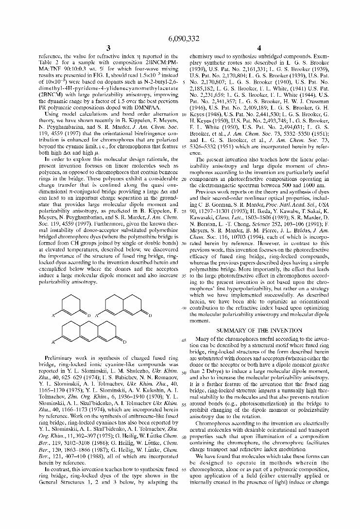
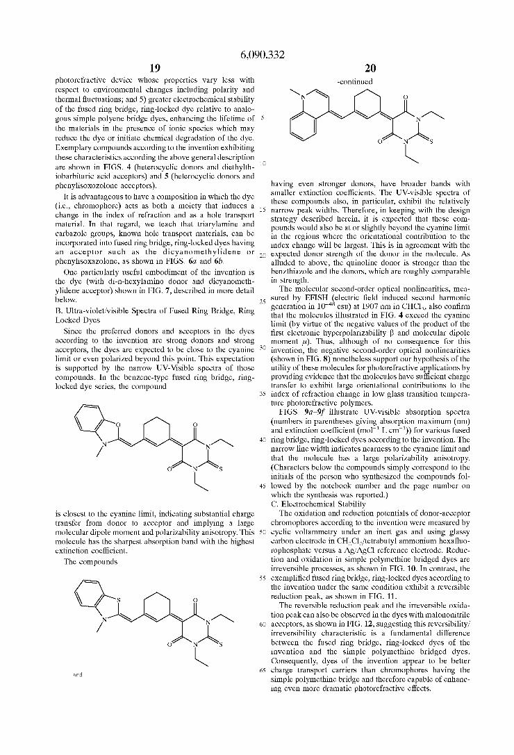
Since the preferred donors and acceptors in the dyes according to the invention are strong donors and strong acceptors, the dyes are expected to be close to the cyanine limit or even polarized beyond this point. This expectation is supported by the narrow UV-Visible spectra of those compounds. In the benzene-type fused ring bridge, ring- locked dye series, the compound
0 ANAS
I
is closest to the cyanine limit, indicating substantial charge transfer from donor to acceptor and implying a large molecular dipole moment and polarizability anisotropy. This molecule has the sharpest absorption band with the highest extinction coefficient.
The compounds
0 ANAS
I and
-continued
10 \
having even stronger donors, have broader bands with smaller extinction coefficients. The UV-visible spectra of these compounds also, in particular, exhibit the relatively
15 narrow peak widths. Therefore, in keeping with the design strategy described herein, it is expected that these com- pounds would also be at or slightly beyond the cyanine limit in the regions where the orientational contribution to the index change will be largest. This is in agreement with the
20 expected donor strength of the donor in the molecule. As alluded to above, the quinoline donor is stronger than the benzthiazole and the donors, which are roughly comparable in strength.
The molecular second-order optical nonlinearities, mea- 25 sured by EFISH (electric field induced second harmonic
generation in esu) at 1907 nm in CHCl,, also confirm that the molecules illustrated in FIG. 4 exceed the cyanine limit (by virtue of the negative values of the product of the first electronic hyperpolarizability fl and molecular dipole moment p). Thus, although of no consequence for this
30 invention, the negative second-order optical nonlinearities (shown in FIG. 8) nonetheless support our hypothesis of the utility of these molecules for photorefractive applications by providing evidence that the molecules have sufficient charge transfer to exhibit large orientational contributions to the
35 index of refraction change in low glass transition tempera- ture photorefractive polymers.
FIGS. 9a-9f illustrate UV-visible absorption spectra (numbers in parentheses giving absorption maximum (nm) and extinction coefficient (mol-' L cm-')) for various fused
40 ring bridge, ring-locked dyes according to the invention. The narrow line width indicates nearness to the cyanine limit and that the molecule has a large polarizability anisotropy. (Characters below the compounds simply correspond to the initials of the person who synthesized the compounds fol-
45 lowed by the notebook number and the page number on which the synthesis was reported.) C. Electrochemical Stability
The oxidation and reduction potentials of donor-acceptor chromophores according to the invention were measured by
SO cyclic voltammetry under an inert gas and using glassy carbon electrode in CH,Cl,/tetrabutyl ammonium hexafluo- rophosphate versus a AgiAgCl reference electrode. Reduc- tion and oxidation in simple polymethine bridged dyes are irreversible processes, as shown in FIG. 10. In contrast, the
ss exemplified fused ring bridge, ring-locked dyes according to the invention under the same condition exhibit a reversible reduction peak, as shown in FIG. 11.
The reversible reduction peak and the irreversible oxida- tion peak can also be observed in the dyes with malononitrile
60 acceptors, as shown in FIG. 12, suggesting this reversibilityi irreversibility characteristic is a fundamental difference between the fused ring bridge, ring-locked dyes of the invention and the simple polymethine bridged dyes. Consequently, dyes of the invention appear to be better
65 charge transport carriers than chromophores having the simple polymethine bridge and therefore capable of enhanc- ing even more dramatic photorefractive effects.

6,090,332 21
D. Thermal Stability of Fused Ring Bridge, Ring-locked Dyes of the Invention
The thermal stability of fused ring bridge, ring-locked dyes according to the invention was compared to that of the corresponding simple polymethine bridged dye according to the following procedure. The two dyes were heated in a sealed flask at 140" C. in diglyme. The extent of decompo- sition as function of time was monitored by the absence of absorbance at a given wavelength at which the dye is known to absorb. As can be seen in the Table 1, the fused ring bridge, ring-locked dye (left) has within experimental error the same absorbance after 45 hours that the simple polyme- thine bridged dye (right) has after only 1 hour. The results demonstrate that fused ring bridge, ring-blocked dyes according to the invention have at least one significant advantage over corresponding simple polymethine bridged dyes. The improved stability of fused ring bridge, ring- locked dyes according to the invention enhances both the shelf life of devices incorporating the dyes as well as their operating lifetime. Thus, the dyes according to the invention, in general, have greater utility in devices than analogous dyes containing simple polymethine bridge (i.e., (CH), groups) between the donor and acceptor.
TABLE 1
Thermal stability of fused bridge, ring-locked and simple polvmethine bridged dves.
time UV absorbance
/ HO
0 l h 2 h 3 h 7 h
18 h 45 h
100% 83% 66% 65% 65% 64% 45%
0 l h 2 h 3 h 6 h
22 h
100% 48% 46% 42% 34% 15%
E. General Synthetic Methodology
The first step of synthesis of fused ring bridge, ring locked dyes according to the invention is the Birch reduction of 1,3-dimethoxybenzene, 2,7-dimethoxynaphthalene or 2,8- dimethoxyanthracene using ethanol, liquid ammonia and sodium. The reduced compounds are the starting materials for the synthesis of the dyes, as shown below.
22
5 M e 0 OMe
aOMe M e 0
10
OMe
15
M e 0
20 J
M e 0 OMe 25
M e 0
1 30
OMe 35
M e 0
The Birch reduction products of 1,3-dimethoxybenzene and of 2,7-dimethoxynaphthalene each react with thiobarbituric
40 acid to form the conjugated methoxy-thiobarbituric acid dyes as shown in FIG. 13. For this reaction, no solvent is used. The reactants were melted at 145" C. for 15 min. Methanol condensing at the walls of the flask showed successful reaction. Purification was carried out by simple
45 filtration over a short column of SiO, with CH,Cl,. Yields were typically around 60%.
Molecules produced according to the reaction scheme of FIG. 13 (i.e., molecules A, B, C or D) can be reacted with amines to give polarized fused ring bridge, ring-locked dyes
SO having large dipole moments and polarizability anisotropies, as exemplified in the reaction scheme shown in FIG. 6a.
Triphenylamine-substituted derivatives with improved transport properties were made in five-step synthesis with 40% overall yield, as exemplified in the reaction scheme
Carbazole derivatives were also synthesized in five steps with overall 48% and 56% yield as illustrated in the reaction scheme of FIG. 15.
The reactivity of the triphenylamine derivatives and car- 60 bazole derivatives depends on the substitutions on the amino
group. Large alkyl groups such as hexyl slowly react and yield relatively little product. Small groups such as methyl react relatively faster and with better yield, as illustrated in the reaction scheme of FIG. 16.
ss illustrated in FIG. 14.
65 General Synthetic Method 1: Each of compounds A and B is reacted further with an
alkylated heterocyclic salt to form the corresponding fused
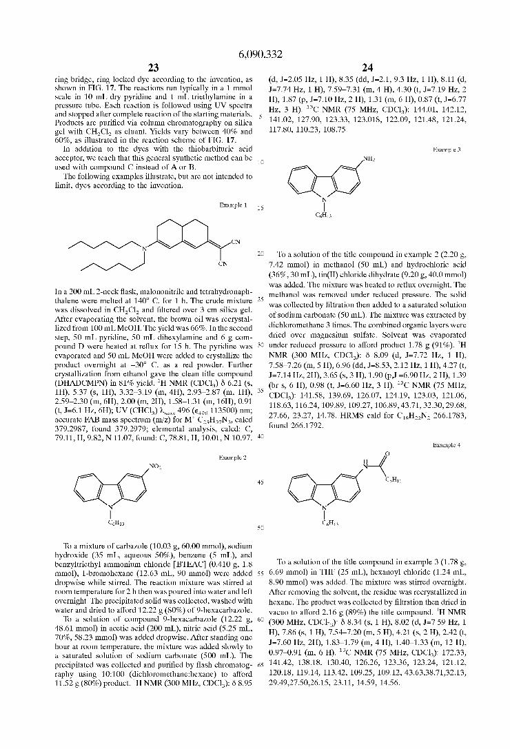
6,090,332 23 24
ring bridge, ring locked dye according to the invention, as shown in FIG. 17. The reactions run typically in a 1 mmol
pressure tube. Each reaction is followed using UV spectra and stopped after complete reaction of the starting materials. 5
gel with CH,Cl, as eluant. Yields vary between 40% and 60%, as illustrated in the reaction scheme of FIG. 17.
acceptor, we teach that this general synthetic method can be used with compound C instead of A or B.
The following examples illustrate, but are not intended to limit, dyes according to the invention.
(d, J=2.05 Hz, 1 H), 8.35 (dd, J=2.1, 9.3 Hz, 1 H), 8.11 (d, J=7.74 Hz, 1 H), 7.59-7.31 (m, 4 H), 4.30 (t, J=7.19 Hz, 2
Hz, 3 H). I3C NMR (75 MHz, CDC1,): 144.01, 142.12,
117.802 110.232 108.75.
in lo mL dry pyridine and mL in a H), 1.87 (p, J=7.10 Hz, 2 H), 1.31 (m, 6 H), 0.87 (t, Jdj.77
Products are purified via column chromatography on silica 141.022 127.902 123.33, 123.0182 122.092 121.48, 121.24,
In addition to the dyes with the thiobarbituric acid Example 3 wNH2 N
CnHiz I Example 1 1s
20 To a solution of the title compound in example 2 (2.20 g, 7.42 mmol) in methanol (50 mL) and hydrochloric acid (36%, 30 mL), tin(I1) chloride dihydrate (9.20 g, 40.0 mmol) was added. The mixture was heated to reflux overnight. The
In a 200 mL 2-neck flask, ~alononitrile and tetrahydronaph- methanol was removed under reduced pressure, The solid thalene were h' The crude mixture 2s was collected by filtration then added to a saturated solution was dissolved in CH,Cl, and filtered over 3 cm silica gel. of sodium carbonate (50 mL). The mixture was extracted by After evaporating the solvent, the brown oil was recrystal- lized from 100 mLMeOH, The yield was 66%. In the second dichloromethane 3 times. The combined organic layers were step, 50 m~ pyridine, 50 m~ dihexylamine and 6 dried over magnesium sulfate. Solvent was evaporated pound D were heated at reflux for 15 h. The pyridine was 30 under reduced Pressure to d k ~ d Product 1.78 g (91%). 'H evaporated and 50 mL MeOH were added to crystallize the NMR (300 MHz, CDC1,): 6 8.09 (d, J=7.72 Hz, 1 H), product overnight at -30" C. as a red powder. Further 7.58-7.26 (m, 5 H), 6.96 (dd, J=8.53,2.12 Hz, 1 H), 4.27 (t, crystallization from ethanol gave the clean title compound J=7.14 Hz, 2H), 3.65 (s, 3 H), 1.90 (p,J 4 9 0 Hz, 2 H), 1.39 (DHmCMPN) in 81% Yield. 'H NMR (CDC13) 6 6.21 6 2 (br s, 6 H), 0.98 (t, J=6.60 Hz, 3 H). I3C NMR (75 MHz,
3s CDC1,): 141.58, 139.69, 126.07, 124.19, 123.03, 121.06, 2'59-2'30 (m2 6H)2 2'oo (m2 2H)2 1'58-1'31 (m2 16H)2 0'91 118.63,116.24,109.89,109.27,106.89,43.71,32.30,29.68, (t, J=6.1 Hz, 6H); UV (CHC1,) h,,, 496 (e,,, 113500) nm; 27.66, 23.27, 14.78. HRMS cald for C,,H,,N, 266.1783, accurate FAB mass spectrum (miz) for M' C,,H,,N,, calcd 379.2987, found 379.2979; elemental analysis, calcd: C, found 266.1792. 79.11, H, 9.82, N 11.07, found: C, 78.81, H, 10.01, N 10.97. 40
CN
at 1400 c' for
5.37 ('3 3.32-3.19 (m, 4H)3 2.93-2.87 (m,
Example 4
Example 2
4s
N N I
C6H13 I
so C6H13
To a mixture of carbazole (10.03 g, 60.00 mmol), sodium hydroxide (35 mL, aqueous 50%), benzene (5 mL), and benzyltriethyl ammonium chloride [BTEAC] (0.410 g, 1.8 TO a solution of the title compound in example 3 (1.78 g, mmol), 1-bromohexane (12.63 mL, 90 mmol) were added ss 6.69 mmol) in THF (25 mL), hexanoyl chloride (1.24 mL, dropwise while stirred. The reaction mixture was stirred at 8.90 mmol) was added. The mixture was stirred overnight. room temperature for 2 h then was poured into water and left After removing the solvent, the residue was recrystallized in
water and dried to afford 12.22 g (80%) of 9-hexacarbazole. (89%) the title compound, 1~ NMR
H), 7.86 (s, 1 H), 7.54-7.20 (m, 5 H), 4.21 (s, 2 H), 2.42 (t, 48.61 mmol) in acetic acid (200 mL), nitric acid (5.25 mL, 70%, 58.23 mmol) was added dropwise. After standing one J=7.60 Hz, 2H), 1.83-1.79 (m, 4 H), 1.40-1.33 (m, 12 H), hour at room temperature, the mixture was added slowly to a saturated solution of sodium carbonate (500 mL). The 0.97-0.91 (m, NMR (75 MHz, CDC13): 172.333
precipitated was collected and purified by flash chromatog- 65 141.42, 138.18, 130.40, 126.26, 123.36, 123.24, 121.12, raphy using 1O:lOO (dich1oromethane:hexane) to afford 120.18, 119.14, 113.42, 109.25, 109.12, 43.63,38.71,32.13, 11.52 g (80%) product. 'H NMR (300 MHz, CDC1,): 6 8.95 29.49,27.50,26.15, 23.11, 14.59, 14.56.
overnight. The precipitated solid was collected, washed with hexane, The product was collected by filtration then dried in
9-hexacarbazo1e (12.22 g, 6o (300 MHz, CDCl-,): 6 8.34 (s, 1 H), 8.02 (d, J=7,59 Hz, 1 to afford 2.16
To a Of

6,090,332 25 26
heated to reflux for 1 h. After cooling to room temperature, the mixture was made basic (sodium carbonate, water) and extracted with ether 3 times. The combined organic layers were dried over magnesium sulfate to remove solvent. The product was purified by flash chromatography with ethyl acetate: hexane (1:lO) on silica gel to give 0.35 g (73%) the title compound. 'H NMR (300 MHz, CDC1,): 6 8.29 (d, J=7.67 Hz, 1 H), 7.70-7.41 (m, 5 H), 7.02 (dd, J=8.57, 1.79
H), 2.00 (br t, J=6.50 Hz, 2 H), 1.51 (br s, 6 H), 1.11 (br s, 3 H). I3C NMR (75 MHz, CDC13): 6 143.86,141.67,135.28, 125.92, 124.39, 123.47, 121.00, 118.59, 114.84, 110.02, 109.29, 103.29,43.77, 32.74, 32.31, 29.73,27.66,23.23, 14.66.
Example 5 NHC6H13
N I
10 Hz, 1 H), 4.37 (t, J=7.03 Hz, 3 H), 3.67 (s, 1 H), 3.09 (s, 3 C6H13
The title compound in example 4 (1.00 g, 2.74 mmol) was added to toluene (50 mL) under argon. Borane dimethylsul- fide [BH,SMe,] (2.06 mL, 2.0 M in toluene, 4.11 mmol) was added dropwise at 0" C. to the mixture. The reaction mixture was stirred at 0" C. for 15 min. then was heated to reflux.
carbonate (20 mL, 10% aqueous) was added and the reaction mixture toluene was layer stirred was separated at room temperature and dried over for 30 magnesium min. The 2o -:.aq-p sulfate, and the solvent was evaporated to afford 0.8846 g (92%) product. 'H NMR (300 MHz, CDC1,): 6 8.23 (d, J=7.66 Hz, 1 H), 7.63-7.34 (m, 5 H), 7.02 (d, J=8.54 Hz, 1
1.75-1.54 (m, 12 H), 1.48-1.06 (m, 6 H). I3C NMR (75 MHz, CDC1,): 142.85, 141.51, 135.12, 125.88, 124.24, 123.32, 120.98, 118.51, 115.22, 110.00, 109.24, 103.77, 46.31, 43.72, 32.52, 32.37, 30.53, 29.78, 27.78, 27.71, 30 A Of the in (0.8846 g, 23.46, 23.32, 14.87, 14.80. 2.52 mmol) and compound C (0.8110 g, 2.52 mmol) in
pyridine (15 mL) was heated to reflux for 24 h. The pyridine was evaporated in vacuo and the residue was purified by
3s flash chromatography with hexane: acetone (4:l) on silica gel to give 0.10 g (6.2%) the title compound. IH NMR (300 MHz, CDC1,): 6 8.09 (d, J=7.67 Hz, 1 H), 7.84 (br s, 1 H), 7.58-7.27 (m, 10 H), 4.38 (br, 2 H), 4.0Ck3.5 (br, 3 H), 2.75-2.15 (br, 4 H), 2.0Ck1.55 (br, 4 H), 1.6Ck1.10 (br, H),
After 2 h, the flask was cooled at room temperature, sodium Example 7
\ I \ / N H), 4.35 (t, J=7.00 Hz, 2 H), 3.56 (s, lH), 3.40 (t, J=6.93 Hz, 2s
2 H), 1.96 (t, J=6.73 Hz, 2 H), 1.82 (t, J=6.99 Hz, 2 H), C6H13 0 O/N
Example6 WNHCH3 N
40 0.91 (br, 6 H). MS cald for C,,H,,N,O, 639, found 639. I C 6 H 1 3
Example 8 Ra-deR Formic acid (3.45 mL, 96%, 87.60 mmol) was added dropwise to acetic anhydride (7.03 mL, 74.36 mmol) in a dry 4s 50 mL flask equipped with a reflux condenser under a stream of dry nitrogen. The mixture was maintained at 0" C. for 10 min, then heated at 50-60" C. for 2 h to form formic anhydride transiently. The mixture of formic anhydride was cooled to room temperature and THF (10 mL) was added. To so To a solution of tris(dibenzy1ideneacetone)dipalladium a solution of the title compound in example 31, formic [Pd , (dba) , ] ( 1 . 0 7 4 g , 1 . 1 7 m m o l ) a n d b i s anhydride in THF (7.62 g, 28.60 mmol) was added, then the (diphenylphosphino) ferrocene [DPPF] (0.9754 g, 1.76 mixture was stirred for overnight. Sodium bicarbonate was mmol) in toluene (300 mL) under nitrogen atmosphere was added slowly to the mixture until the solution was basic. The added l-bromo-4-butylbenzene (25 mL, 117.30 mmol) at mixture was extracted with dichloromethane 3 times. The ss mixture was stirred for combined organic layers were dried over magnesium sulfate 10 min, Sodium tert-butoxide (13.53 g, 140.77 mmol) and and the solvent was evaporated to d h d 7.15 g (85%) of n-butylaniline (22.23 mL, 140.77 mmol) were added to the product. mixture and stirred at 90" C. for 12 h. Following the standard
This formanilide (0.50 g, 1.70 mmol) was dissolved in dry 6o workup procedure, the reaction mixture was purified by THF(lOmL).Thesolutionwascooled too0 C., andborane flash c o l u m n c h r o m a t o g r a p h y u s i n g 1O:lOO methylsulfide complex (0.85 mL, 2.0 M in toluene, 1.70 (dich1oromethane:hexane) to afford 29.62 g (90%) of prod- mmol) was added dropwise. After vigorous reaction ceased, uct. 'H NMR (300 MHz, CDC1,): 6 7.20 (d, J=8.36 Hz, 4 H), the resulting mixture was brought to gentle reflux for 2 h. 7.02 (d, J=8.36,4 H), 5.58 (s, 1 H), 2.60 (t, J=7.67 Hz, 4 H), The reaction mixture was cooled to 0" C., then methanol (10 65 1.63 (p, J=7.82 Hz, 4 H), 1.42 (sext, J=7.28 Hz, 4 H), 0.84 mL) was added slowly, and the mixture was stirred for 1 h. (t, J=7.30 Hz, 6H). I3C NMR (75 MHz, CDC1,): 141.81, Hydrochloric acid (2.5 mL) was added and the mixture was 135.88, 129.71, 118.34,35.48,34.45, 22.94, 14.58.
R = n-Bu
temperature and the

27 6,090,332
Example 9
Ri
28
Example 11
o w R; R1= n-Bu
To a solution of tris(dibenzy1ideneacetone)dipalladium (1.1564 g, 1.2629 mmol) and bis(dipheny1phosphino) fer- rocene (1.0502 g, 1.8944 mmol) in toluene (300 mL) under nitrogen atmosphere was added 1-iodo-4-nitrobenzene (31.45, 126.288 mmol) at room temperature and the result- ant mixture was stirred for 10 min. Sodium tert-butoxide (12.14 g, 126.29 mmol) and the title compound in example 8 (29.62 g, 105.24 mmol) were added to the mixture and stirred at 90" C. for 12 h. Following the standard workup procedure, the reaction mixture was purified by flash column chromatography using 10: 100 (ethyl acetate: hexane) to afford 17.0 g (40%) of product. 'H NMR (300 MHz, CDC1,): 6 8.04 (d, J=9.16 Hz, 2 H), 7.22 (d, J=8.16 Hz, 4 H), 7.14 (d, J=8.14 Hz, 4 H), 6.90 (d, J=9.16 Hz, 2 H), 2.66 (t,
Hz, 4 H), 1.00 (t, J=7.24 Hz, 6 H). I3C NMR (75 MHz, J=7.90 Hz, 4 H), 1.64 (p, J=7.90 Hz, 4 H), 1.43 (sext, J=7.33
CDC1,): 6 154.37, 143.62, 141.29, 140.00, 130.39, 127.06, 126.02, 117.60, 35.75, 34.13, 23.00, 14.56. HRMS cald for C,,H,,N,O, 402.2307, found 402.2294.
Example 10
R1
6 R 1 = H
To a solution of tris(dibenzy1ideneacetone)dipalladium (1.007 g, 0.11 mmol) and bis(dipheny1phosphino) ferrocene (0.915 g, 0.165 mmol) in toluene (300 mL) under nitrogen atmosphere was added 1-iodo-4-nitrobenzene (27.39 g, 110.00 mmol) at room temperature and the resultant mixture was stirred for 10 min. Sodium tert-butoxide (12.00 g, 125.00 mmol) and diphenylamine (16.923 g, 100 mmol) were added to the mixture and stirred at 90" C. for 12 h. Following the standard workup procedure, the reaction mixture was purified by flash column chromatography using 1O:lOO (ethyl acetate:hexane) to afford 14.0 g (48%) of product. 'H NMR (300 MHz, CDC1,): 6 8.08 (d, J=9.27 Hz, 2 H), 7.44-7.39 (m, 4 H), 7.39-7.24 (m, 6 H), 6.97 (d,
146.19, 140.68, 130.49, 127.08, 126.30, 126.02, 118.67. J=9.28 Hz, 2 H) I3C NMR (75 MHz, CDC1,): 6 154.03,
1s R1= H
To a solution of the title compound in example 10 (6.50 g, 16.15 mmol) in methanol (250 mL) and hydrochloric acid
20 (36%, 100 mL), tin(I1) chloride dihydrate (19.5 g, 86.42 mmol) was added. The mixture was heated to reflux over- night. The methanol was removed under reduced pressure. The solid was collected by filtration then added to a satu- rated solution of sodium carbonate (100 mL). The mixture
2s was extracted by dichloromethane 3 times. The combined organic layers were dried over magnesium sulfate. The solvent was evaporated under reduced pressure. The crude products were purified by flash chromatography using
3o 20:lOO (ethyl acetate:hexane) to afford 5.50 g (91%) of product. 'H NMR (300 MHz, CDC1,): 6 7.12-7.03 (m, 10 H), 6.69 (d, J=8.54 Hz, 2 H), 3.54 (br s, 2 H), 2.64 (t, J=7.83 Hz, 4 H), 1.69 (t, J=7.81 Hz, 4 H), 1.47 (sext, J=7.44 Hz, 4 H), 1.04 (t, J=7.27 Hz, 6 H). I3C NMR (75 MHz, CDC1,):
35 6 146.77, 143.13, 140.05, 136.47, 129.47, 127.91, 123.08, 116.72, 35.60, 34.40, 23.08, 14.67.
Example 12 Ri
so R1 = n-Bu
To a solution of the title compound in example 8 (9.00 g, ss 31.00 mmol) in methanol (300 mL) and hydrochloric acid
(36%, 100 mL), tin(I1) chloride dihydrate (36 g, 160 mmol) was added. The mixture was heated to reflux overnight. The methanol was removed under reduced pressure. The solid was collected by filtration then added to a saturated solution
60 of sodium carbonate (100 mL). The mixture was extracted by dichloromethane 3 times. The combined organic layers were dried over magnesium sulfate. The solvent was evapo- rated under reduced pressure to afford 8.10 g (100%) of product. 'H NMR (300 MHz, CDC1,): 6 7.30-7.25 (m, 4 H),
6s 7.14-6.97 (m, 8 H), 6.70 (d, J=8.58 Hz, 2 H), 3.63 (br s, 2 H). I3C NMR (75 MHz, CDC1,): 6 148.58, 143.54, 139.53, 129.60, 128.42, 123.13, 122.08, 116.82.

29 6,090,332
30 The formanilide (3.19 g, 11.06 mmol) was dissolved in
dry THF (35 mL). The solution was cooled to 0" C., and boranemethylsulfide complex (11 mL, 2.0 M in toluene, 22.13 mmol) was added dropwise. After vigorous reaction
s ceased, the resulting mixture was brought to gentle reflux for 2 h. The reaction mixture was cooled to 0" C., then methanol (10 mL) was added slowly and the mixture was stirred for 1 h. Hydrochloric acid (2.5 mL) was added and the mixture was heated to reflux for 1 h. After cooling to room
i o temperature, the mixture was made basic (sodium carbonate, water) and extracted with ether 3 times. The combined organic layers were dried over magnesium sulfate, removal of solvent gave 2.83 g (93.4%) of the product. 'H NMR (300 MHz, CDC1,): 6 7.50-7.00 (m, 12 H), 6.68 (d, J=8.69 Hz,
IS 2 H), 3.60 (br s, 1 H), 2.93 (s, 3 H). I3C NMR (75 MHz, CDC1,): 6 149.04, 146.97, 138.31, 129.61, 128.71, 123.01, 121.96, 113.98, 31.64.
Example13 R
NHC6H13.
Q
Example 15
R R = H o+ dropwise stirred mixture at was 0" at 0" C. cooled C. for above 15 to min. room mixture. then temperature, was The refluxed reaction sodium for mixture 2 carbonate h. After was 2s p N H c H 3
To a solution of the title compound in example 11 (3.00 g, 11.48 mmol) in THF (50 mL), hexanoyl chloride (1.92 mL, 13.77 mmol) was added. The mixture was stirred overnight. After removing the solvent, the residue was 2o recrystallized in hexane. The product was collected by filtration then dried in vacuo . The dried product was added to toluene (50 mL) under argon. Borane-dimethylsulfide (6.11 mL, 2.0 M in toluene, 12.22 mmol) was added
R Q (20 mL, 10% aqueous) was added and the reaction mixture was stirred at 20" C. for 30 min. The toluene layer was separated and dried over magnesium sulfate, and the solvent 30 was evaporated to afford 3.08 g (78%) product. 'H NMR R
R = n-Bu (300 MHz, CDC1,): 6 7.52-7.00 (m, 10 H), 6.77 (d, J=8.24 Hz, 2 H), 3.74 (br s, 1 H), 3.33 (t, J=6.70 Hz, 2 H), 1.87-1.85 (br, 1.63-1.21 (br, l.19 (br, NMR (75 This compound was synthesized in the same manner as MHz, CDC1,): 6 149.19, 146.39, 138.16, 129.78, 128.92, 3s described for compound example 14. Yield is 86%. 'H NMR 123.14, 122.07, 114.35, 45.06, 32.5430.44, 27.75, 23-54? (300 MHz, CDC1,): 6 7.40-7.00 (m, 10 H), 6.68 (d, J=8.60 15.01. Hz, 2 H), 3.67 (br s, 1 H), 2.94 (s, 3 H), 2.71 (t, J=7.83 Hz,
4H),1.75(p,J=7.9Hz,4H),1.52(sext,J=7.5Hz,4H),1.11
146.58, 138.97, 136.30, 129.45, 128.18, 123.03, 113.91, 35.61, 34.33, 31.62, 23.04, 14.57.
Example 14 4o (t, J=7.3 Hz, 6 H). I3C NMR (75 MHz, CDC1,): 6 147.05,
R = H
Example 16
CH3
Formic acid (1.34 mL, 96%, 34.00 mmol) was added ss R R = H dropwise to acetic anhydride (2.74 mL, 28.94 mmol) in a dry
50 mL flask equipped with a reflux condenser under a stream of dry nitrogen. The mixture was maintained at 0" C. for 10 A solution of the title compound in example 14 (2.83 g, min, then heated at 5&6O0 C. for 2 h. The mixture was 10.33 mmol) and compound C (1.50 g, 4.67 mmol) in cooled to room temperature and THF (10 mL) was added. 60 pyridine (10 mL) was heated to reflux overnight. The The title compound in example 11 (2.91 g, 11.13 mmol) was pyridine was evaporated itn vacuo and the residue was added, then the mixture was stirred for overnight. Sodium purified by flash chromatography with hexane: acetone (4:l) bicarbonate was added slowly to the mixture until the on silica gel to give 1.37 g (52%) the title compound. 'H solution was basic. The mixture was extracted with dichlo- NMR (300 MHz, CDC1,): 6 I3C NMR (75 MHz, CDC1,): 6 romethane 3 times. The combined organic layers were dried 65 7.84 (br, 1 H), 7.55 (br s, 5 H), 7.37-7.27 (m, 4 H), over magnesium sulfate and the solvent was evaporated to 7.21-7.11 (m, 5 H), 7.11-7.05 (m, 2 H), 7.02-7.92 (d, afford 3.19 g (99.4%) of product. J=8.66 Hz, 2 H), 5.80 (br s, 1 H), 3.38 (br s, 3 H), 2.60-2.20

6,090,332 31
(br m, 5H), 2.02-1.60 (br m, 2 H), 1.6Ck1.30 (m br, 2 H). HRMS cald for C,,H,,N,O, 564.2651, found 564.2631. Anal. calcd for C,,H,,N,O,: C, 80.96; H, 5.9; N, 7.45. Found; C, 80.46; H, 5.97; N, 7.14.
Example 17
qH3
I\ R = CdHg
A solution of the title compound in example 15 (2.67 g, 6.67 mmol) and compound C (1.61 g, 5.00 mmol) in pyridine (10 mL) was refluxed overnight. The pyridine was evaporated in vacuo and the residue was purified by flash chromatography with hexane: acetone (4:l) on silica gel to give 2.15 g (64%) the title compound. 'H NMR (300 MHz, CDC1,): 6 7.38 (br, 5 H), 7.15 (d, J=8.25 Hz, 4 H), 7.08 (d,
Hz, 2 H), 5.60 (br s, 1 H), 3.37 (s, 3 H), 2.62 (t, J=7.76 Hz, 4 H), 2.44-2.33 (m, 5 H), 1.92-1.81 (m, 3 H), 1.64 (p, J=7.67 Hz, 4 H), 1.41 (sext, J=7.04 Hz, 4 H), 0.98 (t, J=7.23 Hz, 6 H). I3C NMR (75 MHz, CDC1,): 6 202.51, 185.73, 173,51, 167.37, 163.29, 163.00, 162.67, 148.69, 135.25, 139.30, 137.61, 133.75, 129.93, 129.51, 129.49, 128.76, 127.32, 125.84, 122.15, 115.99, 103.87, 100.56, 100.52, 41.96,36.28,35.57,34.03,30.08 29.88,29.67,22.87,14.40, 14.34 h,,=540 nm. HRMS cald for C,,H,,N,O, 676.3903, found 676.3932. Anal. calcd for C,,H,,N,O,: C, 81.74; H, 7.30; N, 6.21. Found; C, 81.81; H, 7.27; N, 6.19.
J=8.23 Hz, 4 H), 7.00 (d, J=8.70 Hz, 2 H), 6.92 (d, J=8.70
Example 18
H3C I n
32 C,,H,,N,O,: C, 80.10; H, 6.89; N, 7.32. Found; C, 79.92; H, 7.01; N, 7.32.
Example 19
1s The title compound in example 6 (5.00 g, 17.84 mmol)
and compound D (3.00 g, 13.20 mmol) was heated to 170" C. under argon for 2 days. The residue was purified by flash chromatography with hexane: acetone: dichloromethane
20 (1OO:lO:lO) on silica gel to give 4.38 g (70%) the title compound. 'H NMR (300 MHz, CDC1,): 6 8.10 (d, J=7.72 Hz, lH), 7.88 (d, J=1.31 Hz, lH), 7.58-7.46 (m, 3 H), 7.33-7.22 (m, 2 H), 6.29 (s, 1 H), 5.57 (s, 1 H), 4.36 (t,
2s J=7.18 Hz, 2 H), 3.50 (s, 3 H), 2.95 (br, lH), 2.57-2.37 (m, 4 H), 2.02-1.91 (m, 4 H), 1.58-1.30 (m, 8 H), 0.92 (t, J=6.8 Hz, 3 H). I3C NMR (75 MHz, CDC1,): 6 68.86, 163.91, 162.34, 141.75, 139.86, 136.97, 127.13, 124.48, 124.08, 122.77, 121.03, 119.95, 118.94, 117.53, 116.83, 112.73,
30 110.14, 109.72, 101.16, 63.93, 43.93, 42.33, 36.17, 32.08, 30.02, 29.97, 29.66, 29.50, 29.45, 29.36, 27.51, 23.07, 14,51. h,,,=491 nm HRMS cald for C,,H,,N, 474.2783, found 474.2799.
R
Example 20
7H3
A solution of the title compound in example 6 (3.41 g, 12.17 mmol) and compound C (3.13 g, 9.74 mmol) in pyridine (5.0 mL) was heated to reflux overnight. The pyridine was evaporated in vacuo and the residue was purified by flash chromatography with hexane: acetone (4:l) on silica gel to give 4.00 g (72%) the title compound. 'H
(d, J=1.58 Hz, 1 H), 7.60-7.20 (m, 11 H), 5.65 (br s, 1 H), 4.35 (t, J=7.23 Hz, 2 H), 3.50 (s, 3 H), 2.6Ck2.20 (br m, 4 H), 2.00-1.70 (br m, 4 H), 1.60-1.20 (br m, 6 H), 0.91 (t,
167.73, 163.92, 163.33, 162.57, 141.82, 140.00, 136.76, 133.81, 129.49, 129.42, 128.75, 127.17, 124.17, 124.14, 122.82, 121.06, 120.00, 118.69 110.16, 109.69, 103.84, 100.15, 43.94, 42.53, 36.26, 32.02, 30.05, 29.88, 29.85, 29.45 27.45, 22.99, 14.36 h,,,=540 nm. HRMS cald for C,,H,,N,O, 570.3121, found 570.3127. Anal. calcd for
NMR (300 MHz, CDC1,): 6 8.09 (d, J=7.74 Hz, 1 H), 7.88
J=6.83 Hz, 3H). I3C NMR (75 MHz, CDC1,): 6 173.60,
50 The title compound in example 15 (6.01 g, 15.00 mmol) and compound D (3.20 g, 14.08 mmol) was heated to 170" C. under Argon for 2 days. The residue was purified by flash chromatography with hexane:acetone:dichloromethane (100:10:30) on silica gel to give 4.08 g (50%) the title
ss compound. 'H NMR (300 MHz, CDC1,): 6 7.15 (d, J=8.34 Hz, 4H), 7.08 (d, J4 .34 Hz, 4 H), 7.03 (d, J=8.75 Hz, 2 H), 6.94 (d, J=8.75 Hz, 2 H), 6.29 (s, 1 H), 5.54 (s, 1 H), 3.37 (s, 3 H), 3.50 (s, 3 H), 2.95 (br, 1 H), 2.62 (t, J=7.53 Hz, 4
6o H), 2.56-2.36 (m, 5 H), 2.04-1.95 (m, 2 H), 1.64 (p, J=7.84Hz, 4 H), 1.55-1.35 (m, 5 H), 0.98 (t, J=7.26 Hz, 6 H). I3C NMR (75 MHz, CDC1,): 6 168.87, 163.83, 161.65, 148.43, 145.30, 139.15, 137.98, 129,95, 127.56, 125.78, 122.27,117.45,116.79,112.81,101.28,64.10,41.81,36.19,
65 35.62, 34.14, 30.04, 29.98, 29.54, 29.46, 22.95, 14,50. h,,,=490 nm. HRMS cald for C,,H,,N, 580.3566, found 580.3577.

6,090,332 33
Example 21
34
Example 24
v R1 = Me, R2 = phenyl
Asolution of N-methyl aniline (1.156 g, 3.60 mmol) and compound C (1.54 g, 14.39 mmol) in pyridine (15 mL) was heated to reflux for 5 h. The pyridine was evaporated in vacuo and the residue was purified by flash chromatography with hexane: acetone (4:l) on silica gel to give 0.92 g (67%) the title compound. 'H NMR (300 MHz, CDC1,): 6 7.8 (br s, lH), 7.6-7.3 (m, 7 H), 7.2 (m, 2 H), 5.8 (br s, 1 H), 3.8 (brs,3H),2.6-2.1(m,5H),1.8(m,2H),1.5-1.2(m,2H). I3C NMR (75 MHz, CDC1,): 164.1, 145.0, 133.6, 130.5, 129.6, 129.4, 128.9, 128.7, 127.0, 115.9, 42.1, 36.0, 29.0, 29.7.
Example 22
R1= R2 = hexyl
This compound was synthesized in the same manner as described for the title compound in example 21. (m, 2 H), 2.6 (m, 2 H), 2.40-1.80 (m, 3 H), 1.7 (br s, 4 H), 1.4 (br s, 14 H), 0.80 (s, 6 H). UV-Vis h,,,=532 nm.
Example 23
CN
Dimethylamino hydrochloride (0.538 g, 6.60 mmol), tri- ethylamine (5.0 mL), compound D and water (0.5 mL) was added to a screw cap tube at 0" C. The tube was capped, then was heated to 80" C. for 2 h. After cooling to room temperature, the mixture was purified by flash chromatog- raphy with hexane:acetone (10:3) on silica gel to give 0.33 g (62%) the title compound. 'H NMR (300 MHz, CDC1,): 6 6.21 (s, 1 H), 5.42 (s, 1 H), 3.21 (s, 6 H), 2.92 (br, 1 H), 2.87 (br, lH), 2.53-2.28 (m, 3 H), 2.08-1.98 (m, 2 H), 1.59-1.39 (m, 2 H). I3C NMR (75 MHz, CDC1,): 6 170.92, 166.47, 164.69, 120.30, 119.59, 114.21, 102.34, 43.17, 38.07, 32.27, 32.10, 31.74, 30.70. h,,=485 nm.
This compound was synthesized in the same manner as described in general synthetic method 1. 'H NMR (CDC1,)
7.27-7.19 (m, 2H), 6.49 (s, lH), 5.78 (s, lH), 4.,62-4.50 (m, 4H), 3.64 (s, 3H), 3.60-3.50 (m, lH), 3.00-2.10 (m, 4H),
2o 2.00 (m, 2H), 1.57-1.47 (m, 2H), 1.31 (t, J=6.9 Hz, 6H); UV (CHC1,) h,,, 698 (e,,, 190000) nm; accurate FAB mass spectrum (miz) for M' C,,H,,N,O,S,, calcd 491.1701, found 434.1783.
1s
6 8.20 (s, lH), 7.61 (d, J=7.7 Hz, lH), 7.45 (t, J=7.7 Hz, lH),
2s Example 25
\ 3s
This compound was synthesized in the same manner as described in general synthetic method 1. 'H NMR (CDC1,) 6 8.19 (s, lH), 7.45 (d, J=7.5 Hz, lH), 7.40-7.20 (m, 2H),
40 7.10(d, J=7.6 Hz, lH), 6.72(s,broad, lH),5.04(s, 1H),4.61 (m, 4H), 3.99 (q, J=7.2 Hz), 2H), 3.6CL3.43 (m, lH), 2.95 (m, 2.95 (m, 2H), 2.75 (m, 2H), 2.45 (m, 2H), 2.00 (m, 2H),
h,,, 672 (e,,, 250000) nm; accurate FAB mass spectrum 4s (rniz) for M' C,,H,,N,O,S, calcd 489.2086, found
489.2083; elemental analysis, calcd: C, 68.69, H, 6.38, N 8.58, found: C, 68.24, H, 6.93, N 8.23.
1.45 (t, J=7.1 Hz, 3H), 1.32 (t, J=6.9 Hz, 6H), UV (CHC1,)
Example 26 so 0
5s
60 This compound was synthesized in the same manner as
described in general synthetic method 1. 'H NMR (CDC1,)
7.56-7.49 (m, 3H), 7.17 (d, 7.3 Hz, lH), 6.66 (s, lH), 6.47 6s (s, 1H), 4.62-4.55 (m, 4H), 3.92-3.42 (m, lH), 3.00-2.60
(m, 4H), 2.46 (m, 2H), 1.97 (m, 2H), 1.56 (s, 3H), 1.32 (t, J=6.9 Hz, 6H); UV (CHC1,) h,,, 800 (e,,, 78500) nm.
6 8.18 (d, J 4 . 2 Hz, lH), 7.97 (s, lH), 7.74 (t, J=7.7 Hz, lH),

35 6,090,332
36
Example 27
10
Example 30
This compound was synthesized in the same manner as described for the title compound in example 1. 'H NMR (CDC1,) 6 7.46-7.34 (m, 3H), 7.14-7.11 (m, 2H), 6.28 (s, lH), 5.49 (s , lH), 3.34 (s , 3H), 2.96-2.91 (m, lH), 2.50-2.33 (m, 4H), 2.00-1.87 (m, 2H), 1.54-1.43 (m, 2H), accurate FAB mass spectrum (mniz) for M' C,,H,,N,, calcd 301.1579, found 301.1569; elemental analysis, calcd: C, 79.70, H, 6.35, N 13.94, found: C, 79.73, H, 6.32, N 14.62.
Example 28
OH < This compound was synthesized in the same manner as
described for the title compound in example 1. 'H NMR (d,-acetone) 6 6.05 (s, lH), 5.73 (s, lH), 4.17 (m, 2H), 3.82-3.65 (M, 8H), 3.00-2.94 (M, lH), 2.78-2.37 (m, 6H, 1.47-1.36 (m, 2H), UV (CHC1,) h,, 490 (e,,, 80000) nm; accurate FAB mass spectrum (rniz) for M' C,,H,,N,O,, calcd 299.1634, found 299.1634; elemental analysis, calcd: C, 68.21, H, 7.07, N 14.04, found: C, 68.61, H, 7.05, N 14.49.
Example 29
0 ANAS
I
1s This compound was synthesized in the same manner as described in general synthetic method 1. 'H NMR (CDC1,) 6 8.30 (s, broad, lH), 7.47-7.27 (m, 3H), 7.18 (d, J=7.7 Hz, lH), 5.60 (s, broad, lH), 4.60 (q, J=6.9 Hz, 4H), 4.05 (q, J=7.2 Hz, 2H), 3.18 (t, J=6.1 Hz, 2H), 3.00 (s, broad, 2H),
20 2.0Ck1.90 (m, 2H), 1.45 (t, J=7.2 Hz, 3H), 1.33 (t, J=6.9 Hz, 6H); UV (CHC1,) h,,, 574 (e,,, 182000) nm; accurate FAB mass spectrum (rniz) for M' C,,H,,N,O,S, calcd 438.1851, found 438.1876; elemental analysis, calcd: C, 65.88, H, 6.22, N 9.60, found: C, 65.88, H, 6.71, N 9.48.
2s Example 31
This compound was synthesized in the same manner as described in general synthetic method 1. 'H NMR (CDC1,) 6 8.4Ck8.28 (m, 2H), 7.81(t, J=7.7 Hz, lH), 7.71 (d, J=7.2
40 Hz, lH), 7.62-7.55 (m, 2H), 7.46 (d, J=7.2 Hz, lH), 6.71 (s,
2H), 2.75 (t, J=5.8 Hz, 2H), 1.91 (m, 2H), 1.33 (t, J=6.8 Hz, 6H); UV (CHC1,) h,,, 702 (e,,, 104000) nm; accurate FAB mass spectrum (rniz) for M' C,,H,,N,O,S, calcd 433.1824,
4s found 438.1814; elemental analysis, calcd: C, 69.26, H, 6.28, N 9.69, found: C, 68.94, H, 6.18, N 10.06.
lH), 4.60 (q, J=6.8 Hz, 4H), 4.02 (s, 3H), 3.12 (t, J=6.0 Hz,
Example 32
This compound was synthesized in the same manner as described in general synthetic method 1. 'H NMR (CDC1,)
7.32 (t, J=8.4 Hz, 2H), 6.20 (s, broad, lH), 4.60 (q, J=6.9 Hz,
2.05-1.94 (m, 2H), 1.32 (t, J=6.9 Hz; UV (CHC1,) h,,, 606 (e,,, 110000) nm; accurate FAB mass spectrum (rniz) for M' C,,H,,N,O,S,, calcd 439.1388, found 439.141 1; elemental analysis, calcd: C, 62.84, H, 5.73, N 9.56, found: C, 62.03, H, 6.16, N 9.12.
6 8.43 (s, lH), 7.70 (d, J=7.7 Hz, lH), 7.51 (t, J=7.7 Hz, lH),
4H), 3.73 (s, 3H), 3.18 (t, J=6.2 Hz, 2H), 2.72 (t, J=6.0 Hz),
60 This compound was synthesized in the same manner as described in example 1 except that intermediate compound A was used instead of intermediate compound D. 'H NMR (CDC1,) 6 8.27 (s, lH), 7.56-7.38 (m, 3H), 7.18 (d, J=7.8
6s Hz, 2H), 2.28 (broad, 2H), 1.90-1.75(m, 2H), 1.32 (t, J=6.8 Hz, 6H), accurate FAB mass spectrum (rniz) for M' C,,H,,N,O,S, calcd 383.1667, found 383.1667.
Hz, 2H), 4.58 (q, J=6.8 Hz, 4H), 3.61 (s, 3H), 3.20 (t, J=6.0

37 6,090,332
38 with a low T, exhibit an orientational contribution to the refractive index modulation. Accordingly, the figure of merit and the design criteria for the chromophores change. The so-called orientational enhancement effect is due to the
5 ability of the chromophores to orient at room temperature under the influence of the total electric field which is the superposition of the internal modulated field and the exter- nally applied field. As a result, in steady state, after photo- refractive hologram formation, the molecules no longer have a uniform orientation but rather have an orientation that is spatially modulated both in magnitude and in direction as schematically illustrated shown in FIG. 18. The periodic orientation of the chromophores doubles the effect of the electrooptic contribution and, more importantly, leads to a modulated birefringence that significantly enhances the total
of the oriented gas model the change in refractive index 2o induced by a poling field applied along a z axis for an optical
refractive index modulation. This modulated birefringence can be easily understood by recalling that a macroscopic change in orientation of molecules with a polarizability anisotropy A a leads to refractive index changes. In the frame
wave polarized along that axis is given by
~~~~~l~ 33
\ / i 10
\ / Q - , This compound was synthesized in the Same m~nner as
described in general synthetic method 1. The compound had broad Peaks in Proton NMR uv (CHC13) ' m a
588 (€588 92000) nm; accurate FAB 'pectrum (miz) for M' C,,H,,N,O,S, calcd 400.1245, found 400.1247.
34
where n is the refractive index, E the poling field, 0 is the orientation angle, F(')=(n2+2)/3 is the Lorentz-Lorenz local field correction factor, and N the density of chromophores.
30 On a microscopic level, the new figure of merit for chro- mophores according to the invention leading to the orien- tational refractive index changes described by equation 3 is consequently Asp'. When both the orientational birefrin- gence and the electrooptic effects contribute to the total
described in general synthetic method 1. The compound had 35 refractive index modulation amplitude, the new figure of broad Peaks in Proton NMR merit F is defined by equation 1 above. For this study, the 562 (%62 115000) nm; accurate FAB temperature was 300 K, a typical operating temperature for for M' C,,H,,N,O,, calcd 398.1630, found 398.1644. low T, photorefractive polymers.
To probe how F varies as a function of the BOA (related 40 to the extent of charge transfer or polarization in the ground
state of the molecule), we analyzed the results of semiem- pirical INDO calculations performed on (CH,), N(CH=CH),CHO in the presence of an external field applied along the long axis z of the molecule shown in FIG.
45 19. For a given field strength, the geometry was optimized and a value of BOA was determined. Electronic states were calculated using configuration interaction with full single and limited double configuration excitations. Then, A a and fl were evaluated using the Sum-Over-States (SOS)
50 approach derived from perturbation theory, using the 30 lowest energy states to obtain converged values. As dis-
This compound was synthesized in the same manner as cussed previously, flp exhibits two extrema with a negative described in general synthetic method 1. The compound had maximum at a value of roughly 0.2 BOA, which corre- broad peaks in proton NMR spectrum; UV (CHC1,) hma sponds to molecules that are somewhat polarized beyond the 696 (e,,, 51000) nm; accurate FAB mass spectrum (miz) for 55 BOA=O, the cyanine limit (FIGS. 20a and 20b). The calcu- MP' C,,H,,N,O,, calcd 398.1630, found 398.1644. lations indicate that a',>>a',, ayy, thus Aa-a',. Previously, F. Exemplary Applications we have shown that a', exhibits a peak at BOA=O for this
Polymer compositions containing molecules according to molecule. In addition, we have demonstrated p that essen- the present invention showed nearly 100% four-wave mix- tially increases with BOAover the region considered in this ing diffraction efficiency in 105 pm thick and net gain 60 study, and thus, p' increases quadratically with BOA. As a coefficients in excess of r=200 cm-' at an applied field of 50 consequence, Aap' has its peak shifted to greater polariza- Vipm. In conventional photorefractive materials, the refrac- tion (higher BOA) than is observed at the cyanine limit and tive index modulation arises solely from the space-charge exhibits a peak at roughly the BOA where flp peaks. field acting on the electrooptic (Pockels) effect of the mate- However, it is important to note that the two contributions rial. Thus, the molecular figure of merit developed for high 65 are opposite in sign. It is therefore necessary to consider T, photorefractive polymers is related to flp/M as for purely their relative magnitudes. Such a comparison is shown in electrooptic polymers. In contrast, photorefractive polymers FIG. 20a where we have plotted A(T)Aa$and flp as a
This compound was synthesized in the Same m~nner as
uv (CHC13) ' m a
(miz)
Example35

6,090,332 39
function of BOA. As can be seen from FIG. 204 in the region where A(T)Aap2 and flp peak, the magnitude of A(T)A& is over 80 times higher than that of flp. As a result, the contribution of the flp term is almost negligible and [A(T)Ayu’+flp]-A(T)Aapz for this molecule.
In conclusion, our calculations support our molecular design rationale for linear polymethines of this length. Molecules which are somewhat polarized beyond the cya- nine limit will lead to high refractive index changes due to orientational effects in low T, photorefractive polymers. One caveat of this analysis that will be important as the technology allows for the incorporation of longer molecules with significantly higher flp values is the fact that flp will scale more rapidly with length than will A(T)Aap’. This will reduce the ratio of A(T)Aq2 to flp and consequently shift the peak of [A(T)Aap’+flp] to lower values of BOA. However, for molecules of the length that are currently being considered for visible and near-IR photorefractive applications, this effect should only be a minor perturbation.
Example 36
Photorefractive Effect in Dye-Doped Composites
In polymers with a low glass transition temperature (T,), orientational effects were found to be mainly responsible for the high refractive index changes. DMNPAA-based poly- mers showed nearly 100% diffraction efficiency in 105 pm thick samples. However, these early materials suffered from several drawbacks: (i) required high electric fields (60 Vipm) for maximum diffraction; (ii) shelf lifetime at room temperature of heavily doped composites (50% wt. of chromophores) was limited to a few months; and (iii) spectral sensitivity limited to visible wavelengths. To exploit the field-induced orientational effects and to lower the value of the applied field, photorefractive nematic liquid crystals were proposed. High refractive index changes at very low fields were reported. However, these materials suffer from a poor resolution due to the coherence length associated with bulk liquid crystalline nematic phases. In amorphous mate- rials doped with optically active molecules (the so-called chromophores), the applied field can be lowered by opti- mizing the refractive index modulation amplitude. One approach is to increase the chromophore concentration to nearly 100% without forming a crystalline material with poor optical quality. This could be achieved recently by developing glass-forming chromophores. Such materials show improved refractive index modulation amplitude at lower field compared with polymers, but exhibit a slow response time close to a minute. That drawback originates from the challenging task of developing glass-forming chro- mophores that exhibit simultaneously high polarizability and good transport properties.
The polymeric matrix of photorefractive compositions according to the present invention exhibits transport prop- erties enabling sub-second response time, good photochemi- cal and thermal stability and a higher polarizability anisot- ropy without crystallization.
Model calculations for the simple polyene molecule (CH,), N(CH=CH),CHO show that molecules with some
40 what more than half of the charge transferred from the amine to the formyl group will lead to strong orientational effects when used as a dopant in photorefractive polymeric com- positions according to the invention. In particular, linear molecules such as polyenes, as opposed to chromophores that contain benzene rings, exhibit a considerable charge transfer that is confined along the x-conjugated bridge providing large Aa. Based on these results, we synthesized the polyene molecule DHADCMPN (also referred to herein as HR-2-54) shown in Example 1. Its structure differs from the simple polymethine dye to create a suitable photorefrac- tive composition: (i) hexyl groups on the amine donor group for high solubility and low aggregation; (ii) fused ring bridge to prevent photoisomerization, reduce aggregation, and improve thermal and photochemical stability; (iii) stable CN groups to contribute to a large molecular dipole moment.
DHADCMPN was used to dope mixtures of poly(N- vinylcarbazole) (PVK) and ethylcarbazole (ECZ) which act as the photoconducting matrix. The photorefractive proper- ties were tested by four-wave mixing and two-beam cou- pling experiments in the tilted geometry as known in the art.
2s In four-wave mixing experiments, two interfering laser beams formed a phase grating in the polymer. The resulting refractive index modulation is measured by diffracting a third beam on the grating and by measuring the intensity of the diffracted beam. Two-beam coupling experiments are
30 performed to check the photorefractive nature of the optical encoding. Energy exchange between the two interfering laser beams after propagation through the thick polymer is possible at steady-state only if the phase grating and the light
35 interference pattern are phase shifted. These phase shifts are a signature of the photorefractive effect.
20
To compare the performance of DHADCMPN with that of other organic photorefractive materials, we prepared
40 samples of DHADCMPN:PVK:ECZ with 2,4,7- trinitrofluorenone (TNF) as a sensitizer. The specific com- position was 40:38:20:2% wt. The diffraction efficiency corrected for the absorption in the 105 pm sample (normalized diffraction efficiency) measured at 633 nm is shown in FIG. 21. Maximum diffraction was observed at an applied field of 30 Vipm instead of 60 Vipm as for DMNPAA-doped polymers with 50% wt. chromophore loading. Absorption was 220 cm-l, leading to 10% trans-
4s
50 mission.
Absorption was mainly limited by the TNF concentration and by the charge transfer complex formed between TNF and the chromophore. Due to the quadratic dependence of
5s An in electric field, a reduction of the applied electric field by a factor of two to achieve complete diffraction compared with previous polymers indicates that An has been improved by a factor of four. Similarly, An of these new materials outperforms that of amorphous photorefractive glasses by a factor of three. The performance level of polymeric com- positions according to the present invention is compared with other organic photorefractive materials in Table 2. The table shows that the response of polymeric compositions
65 according to the invention was -2s. The photorefractive nature of the signal was confirmed by two-beam coupling experiments at 675 nm.
60

41
TABLE 2
6,090,332 42
Performance of polymeric photorefractive compositions at an applied field of 40 VlMm
change in net gain absorption inverse wavelength index coefficient coefficient response time
Composition h An r A T-1
(wt. %) (nm) (m3) (cm-l) (cm-l) (s-?
- DHADCMPN:PVKECZ: 633 5.01 220 TNF(40:38:20:2) 675 DHADCMPN:PVKECZ: 830 1.85 - 76 .5 TNFDM (40:38:20:2) 2BNCM:PMMA:TNF 676 1.87 69 4 0.012 (90:9.7:9.3) DMNPAA:PVKECZ:TNF 675 1.25 25 8 2 (50:33:16:1)
- - - 120
To enable new medical imaging applications with photo- sample. The refractive index changes were characterized in refractive compositions including fused ring bridge, ring- 20 terms of the response function R and for different frequen- locked dyes of the invention, we extended the compositions' cies of the AC field. At high frequencies, the response is due spectral sensitivity from the visible (e700 nm) to the near IR to electrooptic (i.e., related to flp on a molecular level) and (>goo nm). The need for new real-time holograPhic mate- higher-order effects that can be neglected for sake of sim- rials with sensitivity in this spectral region is driven by plicity, At low frequencies, the response is due to orients- compatibility with the emission of GaAs semiconductor 25 tional effects (i,e,, related to A(T))A& on a molecular laser diodes and commercial solid-state femtosecond lasers, level), The low frequency response was found to be 40 times such as Ti:saPP lasers and good transparency region of higher than that at high frequency, demonstrating that the biological tissues. These two factors suggest the great poten- orientational effect is the dominant contribution in An as tial of dyes according to the invention for optical gating for predicted by the design model ca~cu~ations, imaging through scattering media such as tissues and for 3o To investigate the long term stability of DHADCMPN:
PVK samples, we performed optical scattering experiments valuable new medical diagnosis tools. To extend the spectral sensitivity of compositions accord- as a function of time and temperature, ~ ~ ~ ~ ~ / h ~ ~ ~ polymer
ing to the Present invention to the near-IR, we replaced TNF composites exhibit a typical nucleation period followed by in the DHADCMPN~PVKECZ~TNF with 2343 a crystallization phase. In order to observe crystallization 7-trinitro-9-fluorenylidene malononitrile (TNFDM). FIG. 35 during time periods that are easy to measure, we accelerated 22 shows the linear absorption of the inter-molecular charge- the degradation process by measuring the scattered light transfer complex the latter forms with carbazole moieties from non-encapsulated samples heated to 850 C, (below the and that Of the TNF:carbazole The melting point of the chromophores) in air. The lifetime of a spectral sensitivity is clearly extended UP to 900 nm. DMN- given sample was defined as the onset of crystallization after PfiPVK.ECZ:TNFDM (4@38:20:2% wt.1 Performed sig- 40 the nucleation period. Samples with 40% wt. doping of the nificantly worse compared to the TNF-based samples at 675 dye DMPNM showed a lifetime of 1 min, contrast, nm. Total diffraction could not be observed in four-wave DHADCMpN-based samples with the Same chromophore mixing experiment at 830 nm even at applied field values UP loading had a lifetime of 220 min, a two order of magnitude to 90 Vipm. improvement over DMNPAA-based samples. From these
In contrast, FIG. 23 illustrates the superior performance of 45 data, room temperature shelf lifetimes of several decades DHAD CMPN: PVKECZ: TNFDM samples (40: 38: 20: 2% can be extrapolated, wt.) at 830 nm. The normalized diffraction efficiency shows a maximum at 50 Vipm, exceeding the performance of Example 37 previous polymers at visible wavelengths. FIG. 23 also
Thermally Stable Composites shows a theoretical fit using Kogelnik's couple-wave model 50 for the diffraction efficiency and by using the standard It is known that even highly efficient photorefractive Kukhtarev model for the amplitude of the space-charge field. composites, such as those reported in K. Meerholz, et al., The good agreement between theory and experiment shows Nature, 371, 497 (1994) have a limited shelf life (see C. that the internal space-charge field is saturated and equal to Poga, et al., SPZE Proc., 2526, 82 (1995)) because of phase the component of the applied field along the grating vector ss separation of the constituents, in particular the dipolar for all the field values considered in the experiment. The dopant molecule. In recent years, progress made in improv- linear absorption of the sample at 830 nm was 76 cm-l, ing the shelf life of such composites (see Cox, et al., Appl. leading to 45% transmission. The response time was on the Phys. Lett. 68, 2801 (1996)) and A. Gmnnet-Jepsen, et al., order of one second. Appl. Phys. Lett., 70, 1515 (1997)) accompanied degraded
To validate the design rationale for chromophores accord- 60 performance, such as loss of dynamic range at identical ing to the invention based on the optimization of the applied field compared with the polymers reported in 1994. orientational contribution of An (i.e., A(T) A a p 2 on the Recently, it was shown that by using eutectic mixtures of molecular level), we performed independent frequency- dopant molecules chromophores (E. Hendrickx, et al., Appl. dependent ellipsometry experiments as known in the art. In Phys. Lett. 71,1159 (1997)), materials with anticipated shelf these experiments, electric-field induced refractive index 65 lives of several years can be obtained without any loss in changes were measured in a polymer when an AC electric performance, compared with the photorefractive polymers field was superimposed on a DC field and applied to the reported in 1994 by K. Meerholz, et al. Despite long shelf

6,090,332 43 44
lives at room temperature, E. Hendrickx, et al., Appl. Phys. Lett. 71, 1159 (1997) also showed that accelerated aging studies at temperatures greater than 45" C. and lower than
in composites based on a PVK matrix, do phase separate in s Composition
TABLE 3-continued
the melting point of the dipolar dopant molecule, performed Performance of PTCB-Based Composites
A1 E,$ ~ ~ 0 4 r5 time. (wt %) (cm-? (vipm) %ax3 (SI (cm-l)
In contrast, we have prepared thermally stable composites using DHADCMPN at levels up to 40 wt % in copolymer poly(methy1 methacrylate-co-tricyclodecyl methacrylate- (37,6:49,7:12,1:o,6)
(referred to herein as PTCB; structure shown below) that did not show any sign of degradation after 6 days at 70" C.
DHADCMPN: PTCB : 60.5 31 47 9.9 227 D1P:TNFDM (at 48 Vipm)
co-N-cyclohexyl maleimide-co-benzyl methacrylate) lo DHADCMPN:PTCB: 22.6 28 71 14.3 225 D1P:TNFDM (at SO Vipm)
0
CH3 I
Several DHADCMPN:PTCB compositions tested under 30 the same conditions showed no sign of degradation: DHAD- CMPN:PTCB:TNFDM (40:59:1 wt. % ), DHADCMP-
CMPN:PTCB:DIP:TNFDM (37.6:49.7:12.5:0.18 wt. %), 35 Composition A1 E,$ ~ ~ 0 4 r5 DIP is diphenylisophthalate. Furthermore, in addition to
TABLE 3-continued
N:PTCB:DIP:TNFDM (37.6:49.7:12.1:0.6 wt. %), DHAD- Performance of PTCB-Based Composites
DHADCMPN:PTCB:DIP (37.4:50.3:12.3 wt. %), where (wt %) (cm-? (vipm) %ax3 (SI (cm-l)
enhanced thermal stability, these compositions had superior ~ ~ $ ~ f ~ $ ~ ~ : 1.5 36 78 47 198 performance compared with any previously reported photo- DIP (at SO Vipm) refractive polymer composite of which we are aware. (37.4:50.3:12.3) Therefore, the present invention relates also to the fabrica- 40 tion of thermally stable mixtures of DHADCMPN:PTCB having a high and reversible refractive index change for optical recording and optical processing applications.
'A = absorption coefficient at 633 nm measured versus sample without dye. ZE,, = value of applied electric field at which the diffraction efficiency goes through its first maximum. q,,, = external diffraction efficiency at E,,
The photorefractive properties for DHADCMPN:PTCB: 45 4 ~ 5 0 = time needed to reach 50% of maximum diffraction efficiency. DIP (37.4:50.3:12.3 wt. %) demonstrate that DHADCMPN = gain coefficient at 'pecified
simultaneously performs three different functions in the Although not wishing to be bound by theory, we believe PTCB:DIP matrix: (i) as a photogenerator (Or sensitizer); (ii) that the local dipolar disorder around the dopant molecule providing charge transport; and (iii) inducing large refrac- created by the different monomeric units of the polymer tive index changes. As described herein, the association of so stabilizes the composite to enable thermally stable polymer other multifunctional dyes according to the invention when composites. associated with the PTCB matrix will form thermally stable It is therefore a further object of this invention to fabricate materials. Unlike other Polymer binders (e%., PMMA a composite comprising a dopant molecule with a high (PolYmethYlmethacrYlate), p s (polystyrene)) used conven- dipole moment and large polarizability anisotropy and a tionally for photorefractive composites, PTCB is a cop01~- 5s co-polymer comprising several monomeric units with dif- mer that contains four different monomeric units with dif- fering polarities, The glass transition temperature of the fering polarities. composite can be adjusted by adding a plasticizer at a level
of 10 to 20% wt. or the absorption of the composite can be adjusted by adding a photosensitizer (e.g., TNF, TNFDM or
Imaging through highly scattering media using optical Composition A1 E,,, r5 radiation has received particular attention recently due to (wt %) (cm-? (vilcm) %ax3 (SI (cm-l) potential applications in medical diagnostics. More tradi-
86 tional medical imaging techniques, such as x-ray computed TNFDM (at 50 vipm) 65 tomography, magnetic resonance imaging, single photon (40:59:1) emission computed tomography, positron emission tomog-
raphy and ultrasound, are capable of measuring different
TABLE 3 60 fullerene) at low concentration, typically ~ 5 % wt.
Performance of PTCB-Based Composites
DHADCMPN:PTCB: 84.6 39 40 24

6,090,332 45 46
physical quantities and each have limitations. Imaging with onstrated previously with inorganic crystals such as BaTiO,, optical radiation would provide a complementary and valu- and has important advantages associated with real-time able tool for medical diagnostics. Using optical radiation, erasable recording. Inorganic photorefractive crystals, one can avoid the hazards of ionizing radiation, while however, are generally rather expensive, limited in size and obtaining high spatial resolution (potentially diffraction 5 can exhibit large beam fanning effects in longer crystals limited) images and enjoying distinct advantages over cur- which are a source of noise in imaging. Holographic time- rent clinical ultrasound techniques. Additionally, spectro- gating using photorefractive polymers of the invention, on scopic techniques may be employed to discern functional the other hand, are low cost, able to form large area films, information. However, biological tissue, due to refractive have high reconstruction efficiency in relatively thin layers, index inhomogeneities, scatters optical, but not ionizing, high angular bandwidth, structural flexibility. radiation. As a result, light transmitted by biological tissues Some photorefractive polymer compositions according to consists of photons that have experienced no scattering the invention absorb highly in the spectral region between events (ballistic light), weakly scattered photons that emerge 700 and 900 nm. This absorption is highly desirable for almost collinear with the incident radiation (so-called medical imaging since this is a region of particular trans- “snake-like’’ light) and highly scattered (or diffuse) photons. 1s parency for biological tissue and can be generated by Ballistic and snake-like light provide useful information commercially available, broadly tunable, short-pulse Ti:sap- about absorption centers in the medium for shadowgram phire lasers and efficient and inexpensive laser diodes. The imaging. Conversely, the diffuse light emerges from the photorefractive composition used was DHADCMPN- medium in any direction and usually significantly later than :PVKECZ:TNFDM (25:48:25:2 wt. %). The composition the first arriving (i.e., ballistic and snake-like) light. To use 2o was sandwiched between two 1-mm thick glass slides coated diffuse light for imaging, one is required to model photon with transparent IT0 electrodes. The thickness of the mate- transport and employ algorithms to reconstruct the image. rial was 105 pm. The main challenge when transilluminating scattering FIG. 24 depicts the experimental setup. We used a Ti:sap- media, therefore, is to selectively extract the information- phire laser 10 operating at 800 nm with a pulse duration of bearing ballistic or snake-like light without imaging the 2s -150 fs (full-width half-maximum), a repetition rate of -90 diffuse light. MHz, and an average output power of -250 mW. Imaging
Several methods have been developed to extract the was performed in a degenerate four-wave mixing geometry, ballistic light from the background of scattered light, using using two writing beams 20, 22 subtending an angle of 28” spatial filtering techniques that take advantage of the differ- and interfering in a photorefractive polymeric composition ent k-vectors associated with scattered and unscattered light 3o 24 to generate a hologram. The composition was tilted 55” or the spatial coherence properties of scattered light. These with respect to a bisector of writing beams 20, 22 and was techniques include confocal microscopy, optical heterodyne subject to an applied voltage of 5.5 kv. A bar target 26 was detection and spatially incoherent techniques. Other meth- placed in the path of the object (writing) beam 22 to provide ods rely on temporal stretching of a short pulse of light upon a hologram that was reconstructed by a probe beam 28 scattering. As mentioned above, the least-scattered light 3s counter-propagating with writing (reference) beam 20. Scat- exits the medium earlier than more heavily scattered light, tering medium 30 distorts the hologram by scattering. For and several techniques have been developed to exploit this the best efficiency, writing beams 20, 22 were s-polarized characteristic including incoherent time-gating techniques and probe (reading) beam 28 was p-polarized. The power based on electronics, streak cameras, and optical non- ratio between probe beam 28 and writing beams 20,22 was linearities such as the Kerr effect. There are also coherent 4o controlled by a half-wave plate 32 and a polarizing beam approaches to time-gating, including the “light-in-flight” or splitter 34. A second polarizing beam splitter 36 directed the time-gated holography method, electronic holography, and diffracted beam 38 to a CCD camera 40 (Sony model optical coherence tomography. XC-73). Various mirrors M and lenses L were also included
We used photorefractive polymeric compositions accord- in the experimental set UP. ing to the invention as the recording medium for time-gated 4s The hologram was reconstructed in real-time, underscor- holographic imaging through highly scattering media. This ing the ability to create in vivo dynamic images of biological method offers the advantages of a fast acquisition time since tissue. an entire image can be acquired in a single shot, as opposed The test object used in the imaging experiments was a to point-by-point scanning of certain techniques that employ standard Air Force resolution target positioned in front of the spatial filtering. Thus, the potential exists for real-time so scattering cell. The influence of the size of the particles on imaging based upon further optimization of near-infrared the imaging results was demonstrated by using calibrated sensitive photorefractive polymers. Furthermore, this tech- polystyrene spheres of three different diameters (0.548, nique is straightforward in implementation and does not 1.072 and 2.836 pm). The thicknesses of the cuvettes used involve any computations. were 1 mm and 10 mm. In all cases, similar results have been
In this method, a hologram of an object embedded in a 5s obtained, with the most important factor being the total scattering medium is formed in a photorefractive polymer by attenuation of light. For this reason we show only the results the temporal overlap of a reference pulse and the first obtained with water suspensions of 0.548-pm spheres in the arriving (i.e., least-scattered) light from the stretched image- 10-mm cuvette. bearing pulse. The filtering of the ballistic photons from the FIG. 2% shows the time-gated image recorded with a scattered photons is thus achieved in real-time without any 60 mode-locked Ti:sapphire laser in the photorefractive poly- need for digital processing. The image carried by the bal- meric composition after passing through 10 mm of a 0.06 listic light can then be reconstructed real-time via diffraction vol. % microsphere suspension, corresponding to an effec- of a probe beam (pulsed or continuous-wave). tive optical density of -4.0, as determined from the optical
Holographic time-gating was first proposed Some time attenuation measurements described above. For comparison, ago. It has been implemented in the past by using either 65 1 mm of whole milk has an effective optical density of -5.0. photographic emulsions or electronic holography. In Due to the short coherence length of the Ti:sapphire laser addition, photorefractive holographic time-gating was dem- in continuous-wave (CW) operation, it was also possible to

6,090,332 47
filter scattered light while running the laser cw. FIG. 25b shows the image recorded using cw radiation after passing through 10 mm of the 0.06 vol. % microsphere suspension. In fact, the 1.5-mm coherence length of the laser is equiva- lent to a 5 ps time gate. For comparison, an 8 ps gate was 5 successfully used by Wang, et al., Opt. Lett. 18,241 (1993). In addition, the polarization sensitivity of the holographic recording and the spatial filtering provided by the imaging telescope improve the rejection of the scattered light. Moreover, it is known that scattered light quickly loses its lo coherence after several scattering events, especially in a scattering medium with moving particles (Brownian motion in the case of liquid suspensions). Ultimately, using cw light is advantageous, since it facilitates use of short coherence length laser diodes and allows dramatic cost reduction for a hypothetical practical system based on this technique.
Holographic imaging with photorefractive polymeric compositions according to the invention offers a number of advantages over other imaging techniques. Diffraction effi- 20 ciency achievable with 100-pm thick films of photorefrac- tive polymeric compositions according to the invention is comparable to or exceeds what is typically achieved with near IR-sensitive, several millimeter thick rhodium-doped photorefractive BaTiO, crystals. However, response time of 25 the polymers (close to a second) is considerably faster than that of the crystals (approximately 10 seconds). Using thin layers is also particularly important for holographic imaging since the angular bandwidth of the imaging system is inversely proportional to the interaction length. Therefore, a 30 thin material assures the widest possible angular bandwidth and thus the highest image resolution. In addition to the material advantages mentioned earlier, photorefractive poly- meric compositions according to the invention possess struc- tural flexibility that can lead to significantly improved 35 efficiency via molecular engineering. Altogether, photore- fractive polymeric compositions according to the invention offer greater technological potential than their inorganic counterparts.
We claim: 1. A method, comprising the steps of
providing a low viscosity, optically transparent composite containing a polymer and a molecule at a selected
48
D QA
(1) where D is a member selected from the group con- sisting of NR,R,, OR,, SR,, PR,R,,
Ra'NQ*,
temperature, wherein the molecule is electrically 45 neutral, has a formula D-II-A and a molecular dipole moment p,, D is an electron donor group and has a group dipole moment p,, A is an electron acceptor group and has a group dipole moment p, and II is a carbocyclic fused ring bridge of rotationally locked conjugated x bonds connecting D to 4 and has a tond length alternation L, wherein -0.08 AeL50.06 A, in which at least one of p, or p A 2 2 Debye and the vectorial sum of p,+pA is within an angle of 0260 degrees with respect to p, and also within an angle of 55 0260 degrees of a charge transfer vector cT wherein cT
applying an electric field E to the composite, whereby birefringence induced in the composite is ZlO-' in a period of less than 60 seconds and the molecule in the 60 composite aligns itself in accordance with the applied electric field at the selected temperature.
2. A method according to claim 1, wherein the molecule
is /'h-O*d+pA); and
is further defined by a formula
Ra
40 3 \
and
N N
I Ra I Rb

6,090,332 49 50
(2) A is a member selected from the group consisting of -continued
0 f--.-.: 0
I Rd 6; Rd 10
and an aromatic ring system of up to 20 carbons (excluding substituents); wherein (2.1.2) the ring system is selected from the group NC
consisting of 1s
S, R A O ~
*P ")* and
Rc / N<
20 R A 0 3 q R A 0 1 > R A 0 6 x *
RA04 RA07 RAOS,
RA05
RAK RA09 2s I I
wherein (2.1) R,, R,, R, and R, are independently selected from
the group consisting of H, a linear or branched alkyl group with up to 25 carbons, +CH,CH,O),(CH), 30
-(CH,CH,O),(CH)yCONR,,R,,, where (2.1.1) Ral, Ra2, and R,, are independently selected
from the group consisting of H, a linear or 35
branched alkyl group with up to 25 carbons, and a carbazole attached to the nitrogen of
(CH),CONR,,R,,, except that R,, R,, R,, and R, are not any substituent where A is a divalent 40
element;
o R a l , - ( C H 2 C H 2 0 ) x ( C H ) y N R a 2 R a 3 2
+CH2CH20)x(CH)yNRa2Ra3 Or +CHZCHZo)x
+CH,CH,O),(CH),CN, -(CH,CH,O),(CH),C1, -(CH,CH,O),(CH),Br, -(CH,CH,O),(CH),I, -( CH,CH,O),( CH),Phenyl, -( CH,CH,O),( CH) 45 .Benzyl,
/ / *m / / ' so
m,m / / / ' 5s
65
RA29 RA30
RA36 R ~ 3 7
where A# corresponds to a three digit symbol in the subscript of RA# in which RAo15RA#5RA40, 1 5 # 5 4 0 but for 1 5 # 5 9 , # is preceded by the digit 0; (2.1.2.1) RA# are independently selected from the
group consisting o f H, a linear or branched alkyl group with up to 25 carbons, NR,#,R,,, OR,,,, and phenyl; where
(2.1.2.1.1) RA#l, RA#, and RA#, are indepen- dently selected from the group consisting of H, a linear or branched alkyl group with up to

6,090,332 51 52
25 carbons, phenyl, an aryl group, and a car- bazole group; wherein
(2.1.2.1.1.1) the aryl group or the carbazole group have aromatic ring frameworks of up to 20
branched alkyl group with up to 25 carbons, and a carbazole attached to the nitrogen of +CH,CH,O), (CH)yNRa,Ra3 a n d (CH,CH,O)x(CH)y C0NRa2Ra3; carbons (excluding substituents) selected from
the group consisting of
RB05
p.10 p.og R B 1 1 p A q R B 1 6 >
RB12 RBl5
RB13 RB14
R ~ 2 1
3. A method according to claim 1, wherein the molecule is further defined by a formula
2s
(1) where D is a member selected from the group con- sisting of
NRaRb, OR,, SRa, PRaRb, 30
40
Ra
5s where (2.1.2.1.1.1.1) E is selected from the group consist-
ing of S and 0 and B# corresponds to a three digit symbol in the subscript in RB#, 1 5 # 5 4 9 but for 15#'9, # is preceded by the digit 0;
(2.1.2.1.1.1.2) RB# are independently selected from the group consisting of H, linear or branched 6o alkyl group with up to 25 carbons, and phenyl; and
(3) Re is independently selected from the group consisting of H, a linear or branched alkyl group with up to 25 carbons, -(CH,CH,O),(CH) OR,,, -(CH,CH,O),
(3.1) where R,,, Ra2, and Ra3 are independently selected from the group consisting of H, a linear or
and
(CH)yNRa2Ra3, +CH2CH20fx(CH)yC0NRa2Ra3, 6s

6,090,332 53 54
(2) A is a member selected from the group consisting of -continued
0 f--.-.: 0
I Rd 6; Rd 10
and an aromatic ring system of up to 20 carbons (excluding substituents); wherein (2.1.2) the ring system is selected from the group NC
consisting of 1s
S, R A O ~
*P ")* and
Rc / N<
20 R A 0 3 q R A 0 1 > R A 0 6 x *
RA04 RA07 RAOS,
RA05
RAK RA09 2s I I
wherein (2.1) R,, R,, R, and R, are independently selected from
the group consisting of H, a linear or branched alkyl group with up to 25 carbons, +CH,CH,O),(CH), 30
-(CH,CH,O),(CH),CONR,,R,,, where (2.1.1) Ral, Ra2, and R,, are independently selected
from the group consisting of H. a linear or 35
branched alkyl group with up to 25 carbons, a carbazole a t tached to the n i t rogen of
(CH),CONR,,R,,, except that R,, R,, R,, and R, are not any substituent where A is a divalent 40
element;
O R a 1 , - ( C H 2 C H 2 0 ) x ( C H ) y N R a 2 R a 3 2
+CH2CH20)x(CH)yNRa2Ra3 Or +CHZCHZo)x
+CH,CH,O),(CH),CN, -(CH,CH,O),(CH),C1, -(CH,CH,O),(CH),Br, -(CH,CH,O),(CH),I, -(CH,CH,O),(CH),Phenyl, -(CH,CH,O),(CH), 4s Benzyl,
/ / *m / / ' so
m,m / / / ' 5s
65
RA29 RA30
RA36 R ~ 3 7
where A# corresponds to a three digit symbol in the subscript of RA# in which RAo15RA#5RA40, 1 5 # 5 4 0 but for 1 5 # 5 9 , # is preceded by the digit 0;
(2.1.2.1) RA# are independently selected from the group consisting of H, a linear or branched alkyl group with up to 25 carbons, NR,,,R,,,, OR,,, and phenyl; where (2.1.2.1.1) RA#l, RA#, and RA#, are indepen-
dently selected from the group consisting of H, a linear or branched alkyl group with up to

6,090,332 55 56
25 carbons, phenyl, an aryl group and a car- +CH,CH,O)x(CH)yNRa,Ra3, +CH,CH,O)x(CH)y bazole group, wherein CONR,,R,,; where
(2.1.2.1.1.1) the aryl group or the carbazole group have aromatic ring frameworks of up to 20 carbons (excluding substituents) selected from 5 the group consisting of
(3.1) Ral, Ra2, and R,, are independently selected from the group consisting of H, a linear or branched alkyl group with up to 25 carbons, a carbazole attached to the nitrogen of -(CH,CH,O),(CH),NR,,R,, and
RB03@RB01> R B 0 6 2 * -(CH,CH,O),(CH),Phenyl, (CHXBenzyl, and -(CH,CH,O),
RB04 RB07 RBOS, where Ocxc10 and Ocyc25. 4. A method according to claim 1 wherein the molecule is
15 further defined by a formula
-(CH2CH20)x(CH)yC0NRa2Ra3~
-(CH,CH,O),(CH),CN, +CH,CH,O),(CH),C1, 10 -(CH,CH,O),(CH),Br, -(CH,CH,O),(CH),I,
RB05
R B l l Q L q R B 1 6 , RBIO RB09 2o DmA \ \ \
RB15
I I R ~ 1 2
RB13 RB14 Re Rf R,
25 (1) where D is a member selected from the group con- R B I ~ ~ r b R ~ 2 3 ,
sisting NRaRb, of OR,, SRa, PRaRb, RBZQ RB22
30 RB21
RB27@!+ QA, Ra'"Q
RB~~@~*RB~s, RB30 and 40 @; QA; Ra
R B ~ z ~ G ~ $ R B ~ T R ~ 4 3 RB44 RB45 RB46 so Ra@& \ \
3s R, /" RB28 RB31,
RB29
/" \
RB35
RB36 R ~ 3 7 4s
Q s e , Q-- , and
where 5s (2.1.2.1.1.1.1) E is selected from the group con-
sisting of S and 0, and B# corresponds to a three digit symbol in the subscript in RB#, 1 5 # 5 4 9 but for 1 5 # 5 9 , # is preceded by the
(2.1.2.1.1.1.2) RB# are independently selected from the group consisting of H, a linear or branched alkyl group with up to 25 carbons, and phenyl; and
digit 0; 60 "A* Ra /" Rb /"
(3) Re and Rf are independently selected from the group 65 consisting of H, a linear or branched alkyl group with up to 25 carbons -(CH,CH,O),(CH),OR,,,

S
1s
6,090,332 57 58
(2) A is a member selected from the group consisting of and an aromatic ring system of up to 20 carbons (excluding substituents); wherein (2.1.2) the ring system is selected from the group 0 0
c o n s i s t i n g o f :
0 fL;of----; I
Rd I
Rd 10
RA04
RA05
Rc
* , and Rco2c> * ;
Nc> NC NC
20 R A l l q ry RA16
RA12 RAE,
RA13 RA14
wherein 2s (2.1) R,, R,, R, and R, are independently selected from
the group consisting of H, a linear or branched alkyl group with up to 25 carbons, +CH,CH,O)z(CH)y
30 OR, 1 3
m, / / *m / / ' 3s
40
4s
* I @@ I / '
/ '
5s
60
65
Rm7Q lfi9 Rms RA31,
RA29 RA30
R ~ l 9 q rb R ~ 2 3
RA20 RAZZ, and
RA21
R A 3 4 e fo RA38
R ~ 3 5
RA36 RA37
where A# corresponds to a three digit symbol in the subscript of RA# in which RAo15RA#5RA40, 1 5 # 5 4 0 but for 1 5 # 5 9 , # is preceded by the digit 0; (2.1.2.1) RA# are independently selected from the group consisting of H, a linear or branched aikyl group with up to 25 carbons, NR,,,R,,,, OR,,, and phenyl; where (2.1.2.1.1) RA#1RA#2 and RAlj3 are independently selected from the group consisting o f H, a linear or branched alkyl group with up to 25 carbons, phenyl, an aryl group and a carbazole group; wherein (2.1.2.1.1.1) the aryl group or the carbazole group have aromatic ring frameworks of up to 20 car- bons (excluding substituents) selected from the group consisting of

59
RB02 I
RBK RB09 I I
RB13 RB14
I
RB29 RB30
6,090,332 60
(2.1.2.1.1.1.2) RB# are independently selected from the group consisting of H, a linear or branched alkyl group with up to 25 carbons, and phenyl; and
(3) Re, Rf and R, are independently selected from the group consisting of H; a linear or branched alkyl group with up to 25 carbons; +CH,CH,O),(CH)yOR,,,
S
+CH2CH20)x(CH)yNRa2Ra3, +CHZCHZo)x(CH)y 10 CONR,,R,,, where
(3.1) R,,, Ra2, and R,, are independently selected from the group consisting of H, a linear or branched alkyl group with up to 25 carbons, and a carbazole attached to the nitrogen of +CH,CH,O)x(CH)y NR,,R,, and -(CH,CH,O),(CH)yCONR,,R,,,
1s
-(CH,CH,O)x(CH)yCN, +CH,CH,O),(CH)yC1, -(CH2CH20),(CH)yBr, -(CH,CH,O),(CH),I, -(CH,CH,O),(CH),Phenyl, and -(CH,CH,O),
20 (CHXBenzyl,
where Ocxc10 and Ocyc25.
selected from the group consisting of 5 . A method according to claim 3 wherein the molecule is
2s
3s
0 ANAS
RB36 RB37
yB41 yB48
5s
R ~ 4 4
60
where (2.1.2.1.1.1.1) E is selected from the group con-
sisting of S and 0 and B# corresponds to a three digit symbol in the subscript in RB#, 6s 1 5 # 5 4 9 but for 1 5 # 5 9 , # is preceded by the digit 0;
0 ANAS

6,090,332 61 62
-continued -continued
1s
20 R1= Me, R2 = phenyl R1= R2 = Hexyl
5s
CN 60
OH
65
* * * * *


![United States Patent Patent Number: 5,838,906 Doyle et al ... · United States Patent [19] Doyle et al. US005838906A 5,838,906 Nov. 17, 1998 Patent Number: Date of Patent: [11] [45]](https://static.fdocuments.in/doc/165x107/5f05d4757e708231d414eb8f/united-states-patent-patent-number-5838906-doyle-et-al-united-states-patent.jpg)


